RU2244380C2 - Method for radio communications between mobile objects and stationary object residing at initial center of mobile-objects common route - Google Patents
Method for radio communications between mobile objects and stationary object residing at initial center of mobile-objects common route Download PDFInfo
- Publication number
- RU2244380C2 RU2244380C2 RU2002128677/09A RU2002128677A RU2244380C2 RU 2244380 C2 RU2244380 C2 RU 2244380C2 RU 2002128677/09 A RU2002128677/09 A RU 2002128677/09A RU 2002128677 A RU2002128677 A RU 2002128677A RU 2244380 C2 RU2244380 C2 RU 2244380C2
- Authority
- RU
- Russia
- Prior art keywords
- intermediate transceiver
- radio signals
- radio
- mobile
- station
- Prior art date
Links
- 238000004891 communication Methods 0.000 title claims abstract description 35
- 238000000034 method Methods 0.000 title claims abstract description 23
- 230000033001 locomotion Effects 0.000 claims description 36
- 230000005540 biological transmission Effects 0.000 claims description 21
- 230000036039 immunity Effects 0.000 abstract description 5
- 230000000694 effects Effects 0.000 abstract description 4
- 238000012546 transfer Methods 0.000 abstract description 2
- 239000000126 substance Substances 0.000 abstract 1
- 230000010355 oscillation Effects 0.000 description 15
- 235000014676 Phragmites communis Nutrition 0.000 description 6
- 238000013461 design Methods 0.000 description 6
- 238000012545 processing Methods 0.000 description 6
- 230000035945 sensitivity Effects 0.000 description 5
- 230000014509 gene expression Effects 0.000 description 4
- XLYOFNOQVPJJNP-UHFFFAOYSA-N water Substances O XLYOFNOQVPJJNP-UHFFFAOYSA-N 0.000 description 4
- 230000035939 shock Effects 0.000 description 3
- 230000001133 acceleration Effects 0.000 description 2
- 238000013459 approach Methods 0.000 description 2
- 238000006243 chemical reaction Methods 0.000 description 2
- 230000006866 deterioration Effects 0.000 description 2
- 241000208202 Linaceae Species 0.000 description 1
- 235000004431 Linum usitatissimum Nutrition 0.000 description 1
- 230000003321 amplification Effects 0.000 description 1
- 238000004458 analytical method Methods 0.000 description 1
- 230000000052 comparative effect Effects 0.000 description 1
- 239000004744 fabric Substances 0.000 description 1
- 229920002313 fluoropolymer Polymers 0.000 description 1
- 239000000696 magnetic material Substances 0.000 description 1
- 230000014759 maintenance of location Effects 0.000 description 1
- 238000012544 monitoring process Methods 0.000 description 1
- 238000003199 nucleic acid amplification method Methods 0.000 description 1
- 230000035699 permeability Effects 0.000 description 1
Images


Classifications
-
- Y—GENERAL TAGGING OF NEW TECHNOLOGICAL DEVELOPMENTS; GENERAL TAGGING OF CROSS-SECTIONAL TECHNOLOGIES SPANNING OVER SEVERAL SECTIONS OF THE IPC; TECHNICAL SUBJECTS COVERED BY FORMER USPC CROSS-REFERENCE ART COLLECTIONS [XRACs] AND DIGESTS
- Y02—TECHNOLOGIES OR APPLICATIONS FOR MITIGATION OR ADAPTATION AGAINST CLIMATE CHANGE
- Y02D—CLIMATE CHANGE MITIGATION TECHNOLOGIES IN INFORMATION AND COMMUNICATION TECHNOLOGIES [ICT], I.E. INFORMATION AND COMMUNICATION TECHNOLOGIES AIMING AT THE REDUCTION OF THEIR OWN ENERGY USE
- Y02D30/00—Reducing energy consumption in communication networks
- Y02D30/70—Reducing energy consumption in communication networks in wireless communication networks
Landscapes
- Mobile Radio Communication Systems (AREA)
Abstract
Description
Техническое решение относится к радиосвязи, а именно к способам передачи информации на подвижные объекты с неподвижного объекта, находящегося в начальном пункте общего маршрута движения подвижных объектов.The technical solution relates to radio communications, and in particular to methods of transmitting information to moving objects from a fixed object located at the starting point of the general route of movement of moving objects.
Известен способ спутниковой радиосвязи (см., например, О.В.Головин, Н.И.Чистяков, В.Шварц, И.Хардон Агиляр. Радиосвязь. Под ред. О.В.Головина. - М.: Горячая линия - Телеком, 2001, с.224-279), заключающийся в том, что передают радиосигналы с неподвижного объекта, принимают эти радиосигналы на искусственном спутнике Земли, передают эти радиосигналы с искусственного спутника Земли, принимают эти радиосигналы на подвижном объекте, передают радиосигналы с подвижного объекта, принимают эти радиосигналы на искусственном спутнике Земли, передают эти радиосигналы с искусственного спутника Земли, принимают эти радиосигналы на неподвижном объекте.A known method of satellite radio communication (see, for example, O.V. Golovin, N.I. Chistyakov, V. Schwartz, I. Hardon Aguilar. Radio communication. Edited by O.V. Golovin. - M.: Hot line - Telecom , 2001, p.224-279), which consists in transmitting radio signals from a fixed object, receiving these radio signals on an artificial Earth satellite, transmitting these radio signals on an artificial Earth satellite, receiving these radio signals on a moving object, transmitting radio signals from a moving object, receive these radio signals on an artificial Earth satellite, transmit these radio signals shafts from an artificial Earth satellite receive these radio signals on a fixed object.
Указанный способ позволяет обеспечить большую дальность радиосвязи между наземным неподвижным объектом и подвижными объектами, находящимися на поверхности Земли или вблизи нее, независимо от их маршрутов движения, однако требует выведения спутников радиосвязи на околоземные орбиты и управления их движением и функционированием, что усложняет способ.The specified method allows to provide a large range of radio communication between a ground-based stationary object and moving objects located on the Earth's surface or near it, regardless of their travel routes, however, it requires the launch of radio communication satellites into Earth orbits and control their movement and functioning, which complicates the method.
Вместе с тем значительные высоты орбит спутников (от сотен километров в системах с низкими околоземными орбитами до десятков тысяч километров в системах с высокоэллиптическими и геостационарными орбитами - см., например, Ю.М.Горностаев, В.В.Соколов, Л.М.Невдяев. Перспективные спутниковые системы связи. - М.: Горячая линия - Телеком, 2000, с.71) требуют применения на космической станции, а также на неподвижном и подвижных объектах приемопередающих устройств большой мощности, оснащенных высоконаправленными антеннами.At the same time, significant satellite orbit heights (from hundreds of kilometers in systems with low Earth orbits to tens of thousands of kilometers in systems with highly elliptical and geostationary orbits - see, for example, Yu.M. Gornostaev, VV Sokolov, L.M. Nevdyaev, Promising Satellite Communication Systems - M .: Hot Line - Telecom, 2000, p. 71) require the use of high-power transceiver devices equipped with highly directional antennas on a space station, as well as on fixed and mobile objects.
Однако увеличение мощности приемопередающих устройств вызывает ухудшение их массогабаритных показателей, уменьшение помехоустойчивости различных радиоэлектронных средств, размещенных на неподвижном и подвижных объектах, а также снижение электромагнитной безопасности людей, находящихся на неподвижном и подвижных объектах.However, an increase in the power of transceiver devices causes a deterioration in their overall dimensions, a decrease in the noise immunity of various electronic devices located on fixed and mobile objects, and a decrease in the electromagnetic safety of people on fixed and mobile objects.
Указанный недостаток в сочетании с ограниченными возможностями создания антенн с большим коэффициентом усиления приводит к увеличению объема геометрического пространства, занимаемого данной системой радиосвязи (размеры зоны покрытия земной поверхности одним лучом спутникового ретранслятора достигают сотен километров в диаметре - см. там же, с.78-110), что снижает эффективность способа в условиях одновременной эксплуатации нескольких систем радиосвязи.This drawback, combined with the limited capabilities of creating antennas with a high gain, leads to an increase in the geometric space occupied by this radio communication system (the sizes of the coverage area of the earth's surface with one beam of a satellite repeater reach hundreds of kilometers in diameter - see ibid., Pp. 78-110 ), which reduces the efficiency of the method in the conditions of simultaneous operation of several radio communication systems.
Термин “объем геометрического пространства” характеризует одну из трех основных (наряду с полосой частот и временем работы) составляющих радиочастотного пространства, занимаемого системой радиосвязи (см. Н.А.Логинов. Актуальные вопросы радиоконтроля в Российской Федерации. - М.: Радио и связь, 2000, с.11-12).The term “volume of geometric space” characterizes one of the three main (along with the frequency band and operating time) components of the radio frequency space occupied by the radio communication system (see N. A. Loginov. Actual issues of radio monitoring in the Russian Federation. - M .: Radio and communication , 2000, pp. 11-12).
Известен способ радиосвязи между наземным диспетчерским пунктом и летательным аппаратом (см., например, П.С.Давыдов, П.А.Иванов. Эксплуатация авиационного радиоэлектронного оборудования. Справочник. - М.: Транспорт, 1990, с.88-92), заключающийся в том, что передают радиосигналы с наземного диспетчерского пункта, принимают эти радиосигналы на летательном аппарате, передают радиосигналы с летательного аппарата, принимают эти радиосигналы на наземном диспетчерском пункте.A known method of radio communication between a ground control station and an aircraft (see, for example, P.S. Davydov, P.A. Ivanov. Operation of aircraft electronic equipment. Handbook. - M .: Transport, 1990, p. 88-92), consisting in the fact that they transmit radio signals from a ground control station, receive these radio signals on an aircraft, transmit radio signals from an aircraft, receive these radio signals at a ground control station.
Указанный способ не требует решения сложных задач, присущих спутниковой радиосвязи, и позволяет обеспечить большую дальность радиосвязи с несколькими летательными аппаратами, совершающими полет на больших высотах по произвольным маршрутам.The specified method does not require solving complex problems inherent in satellite radio communications, and allows you to provide a large range of radio communications with several aircraft, flying at high altitudes along arbitrary routes.
Однако дальность радиосвязи с низколетящими летательными аппаратами существенно уменьшается в результате влияния отражения электромагнитных волн от поверхности Земли (см., например, Теоретические основы радиолокации. Под ред. В.Е.Дулевича. - М.: Советское радио, 1978, с.410).However, the range of radio communications with low-flying aircraft is significantly reduced as a result of the influence of reflection of electromagnetic waves from the Earth's surface (see, for example, Theoretical Foundations of Radar. Edited by V.E.Dulevich. - M .: Soviet Radio, 1978, p.410) .
Для увеличения дальности радиосвязи необходимо повышать мощности приемопередающих станций, размещенных на наземном диспетчерском пункте и летательных аппаратах, а также направленность антенн этих приемопередающих станций.To increase the range of radio communications, it is necessary to increase the power of transceiver stations located at the ground control station and aircraft, as well as the directivity of the antennas of these transceiver stations.
Однако увеличение мощности приемопередающих станций вызывает ухудшение их массогабаритных показателей, уменьшение помехоустойчивости различных радиоэлектронных средств, размещенных на диспетчерском пункте и летательных аппаратах, а также снижение электромагнитной безопасности людей, находящихся на диспетчерском пункте и летательных аппаратах.However, an increase in the power of transceiver stations causes a deterioration in their overall dimensions, a decrease in the noise immunity of various electronic equipment located at the control room and aircraft, and a decrease in the electromagnetic safety of people at the control room and aircraft.
Указанный недостаток в сочетании с ограниченными возможностями создания антенн с большим коэффициентом усиления приводит к увеличению объема геометрического пространства, занимаемого данной системой радиосвязи, что снижает эффективность способа в условиях одновременной эксплуатации нескольких систем радиосвязи.This drawback, combined with the limited capabilities of creating antennas with a high gain, leads to an increase in the volume of geometric space occupied by this radio communication system, which reduces the efficiency of the method in the conditions of simultaneous operation of several radio communication systems.
Решаемой технической задачей является улучшение массогабаритных показателей приемопередающих станций подвижных объектов и неподвижного объекта, находящегося в начальном пункте общего маршрута движения подвижных объектов, увеличение помехоустойчивости различных радиоэлектронных средств, размещенных на неподвижном и подвижных объектах, повышение электромагнитной безопасности людей, находящихся на неподвижном и подвижных объектах, сокращение объема геометрического пространства, занимаемого данной системой радиосвязи, а следовательно, повышение эффективности способа в условиях одновременной эксплуатации нескольких систем радиосвязи на основе осуществления радиосвязи с помощью сбрасываемых с первого подвижного объекта маломощных промежуточных приемопередающих станций, оснащенных ненаправленными антеннами.The technical problem to be solved is to improve the overall dimensions of the transceiver stations of moving objects and a fixed object located at the starting point of the general route of movement of moving objects, to increase the noise immunity of various electronic devices located on fixed and moving objects, to increase the electromagnetic safety of people on fixed and moving objects, reduction of the geometric space occupied by this radio communication system, and consequently flax, increasing process efficiency under simultaneous operation of several radio communication systems based on radio communication via discharged from the first mobile object thin intermediate transceiver stations equipped with omni-directional antennas.
Решение технической задачи в способе радиосвязи между подвижными объектами и неподвижным объектом, находящимся в начальном пункте общего маршрута движения подвижных объектов, заключающемся в том, что передают на заданной рабочей частоте радиосигналы с неподвижного объекта, принимают на заданных рабочих частотах радиосигналы на подвижных объектах, достигается тем, что с момента времени первого удаления первого подвижного объекта от неподвижного объекта на расстояние, определяемое по заданным дальностям действия радиопередающей станции, размещенной на неподвижном объекте, и промежуточных приемопередающих станций, с первого подвижного объекта осуществляют сброс промежуточных приемопередающих станций, при этом передача радиосигналов с неподвижного объекта на подвижные объекты состоит в том, что принимают переданные с неподвижного объекта радиосигналы на первой сброшенной с первого подвижного объекта промежуточной приемопередающей станции и передают их, принимают переданные с первой сброшенной с первого подвижного объекта промежуточной приемопередающей станции радиосигналы на второй сброшенной с первого подвижного объекта промежуточной приемопередающей станции и передают их, аналогичным образом осуществляют прием и передачу радиосигналов с помощью других сброшенных в более позднее время с первого подвижного объекта промежуточных приемопередающих станций по направлению передачи радиосигналов от сброшенных промежуточных приемопередающих станций в более ранние моменты времени к сброшенным в более поздние моменты времени, принимаемыми на первом подвижном объекте радиосигналами являются радиосигналы, переданные с последней сброшенной с первого подвижного объекта промежуточной приемопередающей станции, на других подвижных объектах, следующих по общему маршруту движения за первым подвижным объектом, принимают также радиосигналы, переданные со сброшенных с первого подвижного объекта промежуточных приемопередающих станций.The solution to the technical problem in the method of radio communication between moving objects and a fixed object located at the starting point of the general route of movement of moving objects, which consists in transmitting radio signals from a fixed object at a given operating frequency, receiving radio signals at moving objects at given working frequencies, that from the time of the first removal of the first movable object from the stationary object to a distance determined by the specified ranges of the radio transmitting station a station located on a fixed object and intermediate transceiver stations from the first mobile object reset intermediate transceiver stations, while the transmission of radio signals from a fixed object to mobile objects consists in the fact that they receive radio signals transmitted from a fixed object on the first reset from the first mobile object intermediate transceiver station and transmit them, receive transmitted from the first dropped from the first mobile object intermediate transceiver station and the radio signals at the second intermediate transceiver station dropped from the first mobile object and similarly receive and transmit radio signals using other intermediate transceiver stations reset at a later time from the first mobile object in the direction of radio signals transmission from the reset intermediate transceiver stations to earlier times to reset at later times, received at the first moving object, the radio signals are the radio signals transmitted from the last transponder-transceiver station dropped from the first movable object at other movable objects following the general movement path behind the first movable object also receive radio signals transmitted from the intermediate transceiver stations reset from the first movable object.
При передаче радиосигналов с неподвижного объекта на подвижные объекты заданной рабочей частотой радиосигналов, принимаемых на каждой сброшенной с первого подвижного объекта промежуточной приемопередающей станции, кроме первой сброшенной с первого подвижного объекта промежуточной приемопередающей станции, является заданная рабочая частота радиосигналов, передаваемых с промежуточной приемопередающей станции, сброшенной с первого подвижного объекта в ближайший к моменту времени сброса данной промежуточной приемопередающей станции более ранний момент времени, заданной рабочей частотой радиосигналов, принимаемых на первой сброшенной с первого подвижного объекта промежуточной приемопередающей станции, является заданная рабочая частота радиосигналов, передаваемых с неподвижного объекта, заданной рабочей частотой радиосигналов, принимаемых на первом подвижном объекте, является заданная рабочая частота радиосигналов, передаваемых с последней сброшенной с первого подвижного объекта промежуточной приемопередающей станции.When transmitting radio signals from a fixed object to moving objects, the specified working frequency of the radio signals received at each intermediate transceiver station reset from the first mobile object, apart from the first intermediate transceiver station reset from the first mobile object, is the specified working frequency of the radio signals transmitted from the intermediate transceiver station reset from the first moving object to the closest to the time of reset of this intermediate transceiver station and an earlier point in time specified by the operating frequency of the radio signals received at the first intermediate transceiver station discarded from the first mobile object is the given operating frequency of the radio signals transmitted from the fixed object, the given operating frequency of the radio signals received at the first mobile object is the specified operating frequency of the radio signals transmitted from the last dropped from the first mobile object of the intermediate transceiver station.
Термин “подвижный объект” является общепринятым (см., например, Соловьев Ю.А. Системы спутниковой навигации. - М.: Экотрендз, 2000, с.39). К подвижным объектам относятся, в частности, средства наземного, водного и воздушного транспорта, оснащенные средствами радиосвязи, причем подвижные объекты могут не только находиться в движении, но и совершать остановки.The term “moving object” is generally accepted (see, for example, Soloviev, Yu.A. Satellite Navigation Systems. - M.: Ecotrendz, 2000, p. 39). Mobile objects include, in particular, means of land, water and air transport, equipped with radio communications, and mobile objects can not only be in motion, but also make stops.
На фиг.1 условно изображены неподвижный объект, первый подвижный объект и вторые подвижные объекты, радиопередающая станция, первая радиоприемная станция и вторые радиоприемные станции, размещенные соответственно на неподвижном объекте, первом подвижном объекте и вторых подвижных объектах, промежуточные приемопередающие станции, сброшенные с первого подвижного объекта, для случая, при котором неподвижный объект является наземным диспетчерским пунктом, первый подвижный объект и вторые подвижные объекты являются низколетящими летательными аппаратами, число вторых подвижных объектов равно одному, число сброшенных с первого подвижного объекта промежуточных приемопередающих станций равно восьми.1 conventionally shows a stationary object, a first mobile object and a second mobile objects, a radio transmitting station, a first radio receiving station and a second radio receiving station located respectively on a fixed object, a first mobile object and second moving objects, intermediate transceiver stations dropped from the first mobile object, for the case in which the fixed object is a ground control tower, the first moving object and the second moving objects are low flying nymi apparatus, the number of second mobile objects is one, the number of dropped from the first mobile object intermediate transceiver stations is eight.
На фиг.2 условно изображены первая радиоприемная станция, блок управления, измеритель скорости, блок задания, блок сброса, содержащий электропривод, конвейер, размещенные на подвижном объекте, несущие элементы, закрепленные на ленте конвейера, магниты, закрепленные по одному в каждом из несущих элементов, промежуточные приемопередающие станции, размещенные по одной в каждом из несущих элементов, находящихся в верхнем положении, причем к каждой из этих промежуточных приемопередающих станций прикреплен с помощью стропов парашют, для случая, при котором число промежуточных приемопередающих станций равно шести.Figure 2 conditionally shows the first radio receiving station, a control unit, a speed meter, a task unit, a reset unit containing an electric drive, a conveyor placed on a moving object, load-bearing elements fixed to the conveyor belt, magnets fixed one in each of the load-bearing elements , intermediate transceiver stations placed one at a time in each of the bearing elements located in the upper position, with a parachute attached to each of these intermediate transceiver stations, for the case I, in which the number of intermediate transceiver stations is six.
На фиг.3 условно изображена радиопередающая станция.Figure 3 conditionally shows a radio transmitting station.
На фиг.4 условно изображена первая радиоприемная станция.Figure 4 conditionally shows the first radio receiving station.
На фиг.5 условно изображен приемопередающий блок промежуточной приемопередающей станции.Figure 5 conditionally shows the transceiver unit of the intermediate transceiver station.
На фиг.6 условно изображена промежуточная приемопередающая станция.Figure 6 conditionally shows an intermediate transceiver station.
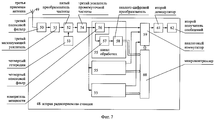
На фиг.7 условно изображена вторая радиоприемная станция.In Fig. 7, a second radio receiving station is conventionally shown.
Система для осуществления способа, представленная на фиг.1-7, содержит размещенные на неподвижном объекте 1 и на первом подвижном объекте 2 радиопередающую станцию 3 и первую радиоприемную станцию 4 соответственно, промежуточные приемопередающие станции 5, размещенные на первом подвижном объекте 2, блок 6 управления, измеритель 7 скорости, блок 8 задания, блок 9 сброса, размещенные на первом подвижном объекте 2, блок 9 сброса содержит электропривод 10, конвейер 11, на ленте 12 конвейера 11 закреплены несущие элементы 13, причем промежуточные приемопередающие станции 5 размещены по одной в каждом из несущих элементов 13, находящихся в верхнем положении, причем к каждой промежуточной приемопередающей станции 5, размещенной в несущем элементе 13, прикреплен с помощью стропов 14 парашют 15, уложенный в данном несущем элементе 13, блок 9 сброса содержит магниты 16, размещенные по одному в каждом из несущих элементов 13, корпус 17 первого подвижного объекта 2 имеет отверстие 18, радиопередающая станция 3 содержит источник 19 сообщений, первый преобразователь 20 частоты, первый гетеродин 21, первый усилитель 22 мощности, первую передающую антенну 23, первая радиоприемная станция 4 содержит первую приемную антенну 24, первый полосовой фильтр 25, первый малошумящий усилитель 26, второй преобразователь 27 частоты, управляемый генератор 28, первый усилитель 29 промежуточной частоты, первый демодулятор 30, первый получатель 31 сообщений, каждая промежуточная приемопередающая станция 5 содержит приемопередающий блок 32 и блок 33 питания, приемопередающий блок 32 содержит вторую приемную антенну 34, второй полосовой фильтр 35, второй малошумящий усилитель 36, третий преобразователь 37 частоты, второй гетеродин 38, второй усилитель 39 промежуточной частоты, четвертый преобразователь 40 частоты, третий гетеродин 41, второй усилитель 42 мощности, вторую передающую антенну 43, блок 33 питания содержит электромагнитное реле 44, геркон 45, аккумулятор 46, система содержит также размещенные по одной на каждом втором подвижном объекте 47 вторые радиоприемные станции 48, каждая из которых содержит третью приемную антенну 49, третий полосовой фильтр 50, третий малошумящий усилитель 51, пятый преобразователь 52 частоты, четвертый гетеродин 53, третий усилитель 54 промежуточной частоты, каналы 55 обработки, число которых на единицу больше числа промежуточных приемопередающих станций 5, размещенных на первом подвижном объекте 2, причем каждый канал 55 обработки содержит четвертый полосовой фильтр 56, измеритель 57 мощности, аналого-цифровой преобразователь 58, каждая вторая радиоприемная станция 48 содержит также аналоговый коммутатор 59, микроконтроллер 60, второй демодулятор 61, второй получатель 62 сообщений.The system for implementing the method shown in Figs. 1-7 comprises a radio transmitting station 3 and a first
Выходы блока 8 задания и измерителя 7 скорости соединены с соответствующими входами блока 6 управления, один из выходов которого соединен с управляющим входом управляемого генератора 28 первой радиоприемной станции 4, другой выход блока 6 управления соединен с входом электропривода 10 конвейера 11, в радиопередающей станции 3 выход источника 19 сообщений соединен с первым входом первого преобразователя 20 частоты, второй вход которого соединен с выходом первого гетеродина 21, выход первого преобразователя 20 частоты соединен с входом первого усилителя 22 мощности, выход которого соединен с входом первой передающей антенны 23, в первой радиоприемной станции 4 выход первой приемной антенны 24 соединен с входом первого полосового фильтра 25, выход которого соединен с входом первого малошумящего усилителя 26, выход которого соединен с первым входом второго преобразователя 27 частоты, второй вход которого соединен с выходом управляемого генератора 28, выход второго преобразователя 27 частоты соединен с входом первого усилителя 29 промежуточной частоты, выход которого соединен с входом первого демодулятора 30, выход которого соединен с входом первого получателя 31 сообщений, в приемопередающем блоке 32 каждой промежуточной приемопередающей станции 5 выход второй приемной антенны 34 соединен с входом второго полосового фильтра 35, выход которого соединен с входом второго малошумящего усилителя 36, выход которого соединен с первым входом третьего преобразователя 37 частоты, второй вход которого соединен с выходом второго гетеродина 38, выход третьего преобразователя 37 частоты соединен с входом второго усилителя 39 промежуточной частоты, выход которого соединен с первым входом четвертого преобразователя 40 частоты, второй вход которого соединен с выходом третьего гетеродина 41, выход четвертого преобразователя 40 частоты соединен с входом второго усилителя 42 мощности, выход которого соединен с входом второй передающей антенны 43, в блоке 33 питания каждой промежуточной приемопередающей станции 5 первый вывод обмотки электромагнитного реле 44 соединен с положительным полюсом аккумулятора 46, второй вывод соединен с первым выводом геркона 45, второй вывод которого соединен с отрицательным полюсом аккумулятора 46, положительный полюс аккумулятора 46 соединен через нормально замкнутые контакты электромагнитного реле 44 с положительной клеммой питания приемопередающего блока 32, отрицательная клемма питания которого соединена с отрицательным полюсом аккумулятора 46, в каждой второй радиоприемной станции 48 выход третьей приемной антенны 49 соединен с входом третьего полосового фильтра 50, выход которого соединен с входом третьего малошумящего усилителя 51, выход которого соединен с первым входом пятого преобразователя 52 частоты, второй вход которого соединен с выходом четвертого гетеродина 53, выход пятого преобразователя 52 частоты соединен с входом третьего усилителя 54 промежуточной частоты, выход которого соединен с входами всех четвертых полосовых фильтров 56, выход четвертого полосового фильтра 56 каждого канала 55 обработки соединен с соответствующим коммутируемым входом аналогового коммутатора 59 и с входом измерителя 57 мощности, выход которого соединен с входом аналого-цифрового преобразователя 58, выходы которого соединены с соответствующими входами микроконтроллера 60, выходы которого соединены с управляющими входами аналогового коммутатора 59, выход которого соединен с входом второго демодулятора 61, выход которого соединен с входом второго получателя 62 сообщений.The outputs of the
Дальность действия радиопередающей станции 3 задана по заданным дальностям действия промежуточных приемопередающих станций 5, частотой настройки первого гетеродина 21 является заданная частота передачи радиопередающей станции 3, частота настройки второго гетеродина 38 каждой промежуточной приемопередающей станции 5 отличается от заданной частоты приема данной промежуточной приемопередающей станции 5 на заданное значение промежуточной частоты последней, частота настройки третьего гетеродина 41 каждой промежуточной приемопередающей станции 5 отличается от заданной частоты передачи данной промежуточной приемопередающей станции 5 на заданное значение промежуточной частоты последней, заданная частота передачи каждой промежуточной приемопередающей станции 5 отличается от заданных частот передачи других промежуточных приемопередающих станций 5, заданной частотой приема каждой промежуточной приемопередающей станции 5, размещенной на первом подвижном объекте 2, кроме промежуточной приемопередающей станции 5, размещенной на минимальном удалении вдоль конвейера 11 от отверстия 18, является заданная частота передачи промежуточной приемопередающей станции 5, размещенной на минимальном удалении от данной промежуточной приемопередающей станции 5 по направлению вдоль конвейера 11 к отверстию 18, заданной частотой приема промежуточной приемопередающей станции 5, размещенной на первом подвижном объекте 2 на минимальном удалении вдоль конвейера 11 от отверстия 18, является заданная частота передачи радиопередающей станции 3, размещенной на неподвижном объекте 1, частоты приема каждой из вторых радиоприемных станций 48 совпадают с соответствующими частотами передачи радиопередающей станции 3 и промежуточных приемопередающих станций 5.The range of the radio transmitting station 3 is set according to the specified ranges of the intermediate transceiver stations 5, the tuning frequency of the first
Сущность способа заключается в следующем.The essence of the method is as follows.
Рассмотрим ситуацию, при которой неподвижным объектом 1 является наземный диспетчерский пункт, первым подвижным объектом 2 и вторыми подвижными объектами 47 являются низколетящие летательные аппараты, например вертолеты или дирижабли.Consider a situation in which the
Маршруты движения первого подвижного объекта 2 и вторых подвижных объектов 47 совпадают.The movement paths of the first
Вторые подвижные объекты 47 следуют по общему маршруту движения за первым подвижным объектом 2.The second movable objects 47 follow the general route of movement for the first
Термин “низколетящий летательный аппарат” является общепринятым (см., например, Радиотехнические системы. Под ред. проф. Ю.М.Казаринова. - М.: Высшая школа, 1990, с.221). Первый подвижный объект 2, в частности летательный аппарат, является низколетящим, если выполняется условие (см. Теоретические основы радиолокации. Под ред. В.Е.Дулевича. - М.: Советское радио, 1978, с.410):The term “low flying aircraft” is generally accepted (see, for example, Radio Engineering Systems. Edited by Prof. Yu.M. Kazarinov. - M .: Higher School, 1990, p. 211). The first
![]()
![]()
где с - скорость света; ha - высота расположения первой передающей антенны 23 радиопередающей станции 3, размещенной на неподвижном объекте 1; hb - высота расположения первой приемной антенны 24 первой радиоприемной станции 4, размещенной на первом подвижном объекте 2; d - расстояние между неподвижным объектом 1 и первым подвижным объектом 2.where c is the speed of light; h a - the height of the first transmitting
Выражение (1) справедливо, если выполняется условие зеркального отражения радиоволн от подстилающей поверхности (см. там же, с.405):Expression (1) is true if the condition for specular reflection of radio waves from the underlying surface is fulfilled (see ibid., P. 405):
![]()
![]()
где Ψ - угол скольжения; δ - высота неровностей подстилающей поверхности.where Ψ is the slip angle; δ is the height of the irregularities of the underlying surface.
Для определенности примем, что подстилающая поверхность, являющаяся поверхностью Земли, представляет собой зеркально отражающую горизонтальную плоскость, т.е. условие (2) выполняется.For definiteness, we assume that the underlying surface, which is the surface of the Earth, is a mirror-reflecting horizontal plane, i.e. condition (2) is satisfied.
На неподвижном объекте 1 размещают радиопередающую станцию 3.On a
На первом подвижном объекте 2 размещают первую радиоприемную станцию 4 и N промежуточных приемопередающих станций 5 с номерами n=1, 2,... ,N, где n - целые положительные числа.At the first
В общем случае с первого подвижного объекта 2 в каждой точке сброса могут осуществлять сброс по несколько промежуточных приемопередающих станций 5.In the General case, from the first
Примем, что с первого подвижного объекта 2 в каждой точке сброса осуществляют сброс только по одной промежуточной приемопередающей станции 5.We assume that from the first
Более ранним моментам времени сброса промежуточных приемопередающих станций 5 с первого подвижного объекта 2 соответствуют промежуточные приемопередающие станции 5 с меньшими номерами:To earlier times of the reset of the intermediate transceiver stations 5 from the first
![]()
![]()
где tn, tν - моменты времени сброса n-й и ν -й промежуточных приемопередающих станций 5 соответственно; ν =1, 2,... ,N - целые положительные числа.where t n , tν are the times of dumping of the nth and νth intermediate transceiver stations 5, respectively; ν = 1, 2, ..., N are positive integers.
На первом подвижном объекте 2 отсчет времени tb ведут от момента времени ![]()
![]()
В начальном пункте О маршрута движения первого подвижного объекта 2 и вторых подвижных объектов 47 находится неподвижный объект 1 (фиг.1).At the starting point O of the movement path of the first
Последней сброшенной с первого подвижного объекта 2 промежуточной приемопередающей станцией 5 является промежуточная приемопередающая станция 5, сброс которой осуществлен в наиболее поздний момент времени:The last intermediate transceiver station 5 discarded from the first
![]()
![]()
где nmax=1, 2,... ,N.where n max = 1, 2, ..., N.
Дальность действия n-й сброшенной с первого подвижного объекта 2 промежуточной приемопередающей станции 5, кроме последней сброшенной с первого подвижного объекта 2 промежуточной приемопередающей станции 5 (n=nmax), равнаThe range of the nth intermediate transceiver station 5 dropped from the first
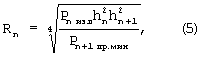
где Рn изл - мощность радиосигналов, передаваемых с n-й сброшенной промежуточной приемопередающей станции 5; Рn+1 пр.мин - некоторая пороговая величина, характеризующая чувствительность (n+1)-й сброшенной промежуточной приемопередающей станции 5; hn, hn+1 - высоты расположения второй передающей антенны 43 n-й и второй приемной антенны 34 (n+1)-й сброшенных промежуточных приемопередающих станций 5 соответственно.where P n out - the power of radio signals transmitted from the n-th reset intermediate transceiver station 5; P n + 1 pr.min - a certain threshold value characterizing the sensitivity of the (n + 1) th reset intermediate transceiver station 5; h n , h n + 1 are the heights of the
Дальность действия последней сброшенной с первого подвижного объекта 2 промежуточной приемопередающей станции 5 равнаThe range of the last dropped from the first

где ![]()
![]()
![]()
![]()
Дальность действия радиопередающей станции 3 неподвижного объекта 1 равнаThe range of the radio transmitting station 3 of the fixed

где Ра изл - мощность радиосигналов, передаваемых с неподвижного объекта 1; Рn пр мин|n=1 - некоторая пороговая величина, характеризующая чувствительность первой сброшенной с первого подвижного объекта 2 промежуточной приемопередающей станции 5; hn|n=1 - высота расположения второй приемной антенны 34 первой сброшенной с первого подвижного объекта 2 промежуточной приемопередающей станции 5.where R a izl - the power of radio signals transmitted from a fixed
Под высотой расположения антенны понимаем расстояние до находящейся под антенной точки подстилающей поверхности.By antenna height we mean the distance to the underlying surface located under the antenna point.
Значение высоты ha расположения первой передающей антенны 23 радиопередающей станции 3 фиксировано и определяется особенностями конструкций и компоновки неподвижного объекта 1 и радиопередающей станции 3.The value of the height h a location of the first transmitting
Высота hb расположения первой приемной антенны 24 первой радиоприемной станции 4 изменяется в диапазоне от hb min до hb max. Минимальное значение высоты hb min достигается, когда первый подвижный объект 2 находится на подстилающей поверхности, и определяется особенностями конструкций и компоновки первого подвижного объекта 2 и первой радиоприемной станции 4. Максимальное значение высоты hb max не превышает сумму значений hb min и максимальной высоты полета Hb max первого подвижного объекта 2.The height h b of the location of the first receiving
Высоты hn расположения вторых приемных антенн 34 и вторых передающих антенн 43 сброшенных с первого подвижного объекта 2 промежуточных приемопередающих станций 5 изменяются в диапазоне значений от hn min до hn max. Минимальное значение высоты hb min достигается, когда n-я промежуточная приемопередающая станция 5 находится на подстилающей поверхности, и определяется особенностями конструкции данной промежуточной приемопередающей станции 5. Максимальное значение высоты hn max соответствует моменту времени сброса n-й промежуточной приемопередающей станции 5 с первого подвижного объекта 2 и не превышает величины hb max.The height h n the location of the
Поскольку маршруты движения вторых подвижных объектов 47 совпадают с маршрутом движения первого подвижного объекта 2, примем, что минимальные hc min и максимальные hc max значения высот расположения третьих приемных антенн 49 вторых радиоприемных станций 48, размещенных на вторых подвижных объектах 47, совпадают соответственно с минимальным hb min и максимальным hb max значениями высот расположения первой приемной антенны 24 первой радиоприемной станции 4, размещенной на первом подвижном объекте 2. Кроме того, примем, что чувствительности вторых радиоприемных станций 48 равны Pс пр.мин.Since the motion paths of the second movable objects 47 coincide with the motion path of the first
Формулы (1), (6) остаются справедливыми при замене в них параметров первой радиоприемной станции 4 на параметры вторых радиоприемных станций 48.Formulas (1), (6) remain valid when replacing the parameters of the first
Выражения (1), (2), (5)-(7) являются приближенными и не учитывают геометрию неподвижного объекта 1, первого подвижного объекта 2, вторых подвижных объектов 47 и промежуточных приемопередающих станций 5.Expressions (1), (2), (5) - (7) are approximate and do not take into account the geometry of the
С учетом изложенного примем, что для всех п справедливы равенстваIn view of the above, we assume that for all η the equalities
![]()
![]()
![]()
![]()
![]()
![]()
![]()
![]()
Из выражений (5), (6) следует, что при выполнении условий (8)-(11) минимально допустимая дальность действия промежуточных приемопередающих станций 5 равнаFrom the expressions (5), (6) it follows that when conditions (8) - (11) are satisfied, the minimum allowable range of operation of the intermediate transceiver stations 5 is
![]()
![]()
По заданным величинам Ризл, Рпр.мин и hmin c учетом формулы (12) дальности действия промежуточных приемопередающих станций 5 задают равнымиAccording to the given values of P rad , P av.min and h min, taking into account formula (12), the operating ranges of the intermediate transceiver stations 5 are set equal
![]()
![]()
Дальность действия радиопередающей станции 3 задают по заданным значениям дальностей действия промежуточных приемопередающих станций 5, например, по формулеThe range of the radio transmitting station 3 is set according to the set values of the ranges of the intermediate transceiver stations 5, for example, by the formula
![]()
![]()
В общем случае при движении по маршруту первый подвижный объект 2 и вторые подвижные объекты 47 могут совершать остановки на произвольные по продолжительности интервалы времени.In the general case, when moving along a route, the first
Предположим, что первый подвижный объект 2 осуществляет из начального пункта О, в котором находится неподвижный объект 1, вертикальный подъем на высоту hb max, а затем совершает горизонтальный полет на высоте hb max с постоянной скоростью Vb вдоль оси х по направлению в сторону возрастающих значений х; максимальное расстояние от неподвижного объекта 1 до первого подвижного объекта 2 равно db max и характеризует протяженность маршрута движения первого подвижного объекта 2.Suppose that the first
До момента времени tb min первого удаления первого подвижного объекта 2 от неподвижного объекта 1 на расстояние db min с первого подвижного объекта 2 сброс промежуточных приемопередающих станций 5 не осуществляют. При этом осуществление способа состоит в том, что передают радиосигналы с неподвижного объекта 1, принимают эти радиосигналы на первом подвижном объекте 2.Until the time t b min of the first removal of the first
Величину db min определяют по заданным дальностям Ra=Rn=Rmin действия радиопередающей станции 3 и промежуточных приемопередающих станций 5.The value of d b min is determined by the given ranges R a = R n = R min of the action of the radio transmitting station 3 and the intermediate transceiver stations 5.
В частности, величину db min можно задать равнойIn particular, the value of d b min can be set equal to
![]()
![]()
где k1≥ 1 - коэффициент запаса, учитывающий приближенный характер применяемых формул.where k 1 ≥ 1 is the safety factor taking into account the approximate nature of the applied formulas.
С момента времени tb min первого удаления первого подвижного объекта 2 от неподвижного объекта 1 на расстояние db min с первого подвижного объекта 2 осуществляют сброс промежуточных приемопередающих станций 5 с интервалами по дальности, определяемыми по заданным дальностям действия радиопередающей станции 3 и промежуточных приемопередающих станций 5.From the time t b min of the first removal of the first
В силу принятых допущений интервал сброса промежуточных приемопередающих станций 5 с первого подвижного объекта 2 может равнятьсяBy virtue of the assumptions made, the reset interval of the intermediate transceiver stations 5 from the first
![]()
![]()
где k2≥ 1 - коэффициент запаса.where k 2 ≥ 1 is the safety factor.
Сброс первой промежуточной приемопередающей станции 5 с первого подвижного объекта 2 осуществляют в момент времени tb min первого удаления первого подвижного объекта 2 от неподвижного объекта 1 на расстояние db min.The reset of the first intermediate transceiver station 5 from the first
Расстояния от неподвижного объекта 1 до первого подвижного объекта 2, на которых осуществляют сброс промежуточных приемопередающих станций 5, можно измерять на первом подвижном объекте 2 с помощью инерциальных или доплеровских систем счисления пути (см. Авиационная радионавигация: Справочник. Под ред. А.А.Сосновского. - М.: Транспорт, 1990, с.6-8).The distances from the
При заданных ранее характеристиках движения первого подвижного объекта 2 сброс n-й промежуточной приемопередающей станции 5 осуществляют в момент времениGiven the previously defined motion characteristics of the first

причемmoreover

где ![]()
![]()
Формула (17) обусловлена тем, что интервалы по дальности Δ dn определяют максимально возможные расстояния между двумя промежуточными приемопередающими станциями 5, сброшенными с первого подвижного объекта 2 в ближайшие моменты времени.Formula (17) is due to the fact that the distance intervals Δ d n determine the maximum possible distances between two intermediate transceiver stations 5 dropped from the first moving
Формула (18) обусловлена тем, что дальность db min определяет максимально возможное расстояние от первого подвижного объекта 2 до неподвижного объекта 1, соответствующее моменту времени tb min.Formula (18) is due to the fact that the range d b min determines the maximum possible distance from the first
В общем случае первый подвижный объект 2 может совершать движение по сложному маршруту. В частности, он может вначале удаляться от неподвижного объекта 1, а затем приближаться к нему, затем вновь удаляться и приближаться и т.д. При этом первый подвижный объект 2 может многократно проходить через начальный пункт О, в котором находится неподвижный объект 1, и, следовательно, многократно находиться от него на расстоянии, меньшем db min. Однако сброс промежуточных приемопередающих станций 5 с первого подвижного объекта 2 не осуществляют только до момента времени первого удаления первого подвижного объекта 2 от неподвижного объекта 1 на расстояние db min. С данного момента времени с первого подвижного объекта 2 осуществляют сброс промежуточных приемопередающих станций 5 с интервалами по дальности, определяемыми по заданным дальностям действия радиопередающей станции 3 и промежуточных приемопередающих станций 5, причем сброс промежуточных приемопередающих станций 5 осуществляют и в том случае, если в результате движения первого подвижного объекта 2 по маршруту расстояние до неподвижного объекта 1 вновь станет меньше величины db min . In the General case, the first
Если скорость ветра пренебрежимо мала, скорость Vb движения первого подвижного объекта 2 также настолько мала, что не вызывает существенного возмущения воздушных масс, то траектории падения промежуточных приемопередающих станций 5 можно принять вертикальными. При этом аэродинамические свойства конструкций промежуточных приемопередающих станций 5 не должны иметь каких-либо особенностей, вызывающих существенное отклонение траекторий падения от вертикальных.If the wind speed is negligible, the speed V b of the first
После падения на подстилающую поверхность промежуточные приемопередающие станции 5 остаются неподвижными.After falling onto the underlying surface, the intermediate transceiver stations 5 remain stationary.
Коэффициент запаса k2 учитывает возможную неточность разброса промежуточных приемопередающих станций 5, обусловленную влиянием различных факторов.The safety factor k 2 takes into account the possible inaccuracy of the scatter of the intermediate transceiver stations 5, due to the influence of various factors.
Возможны два характерных случая:Two characteristic cases are possible:
![]()
![]()
![]()
![]()
При движении первого подвижного объекта 2 по маршруту, продолжительность которого равна ![]()
![]()
В первом случае (19, а) с первого подвижного объекта 2 сброс промежуточных приемопередающих станций 5 не осуществляют. Осуществление способа в данном случае рассмотрено выше.In the first case (19, a), the intermediate transceiver stations 5 are not reset from the first
Рассмотрим осуществление способа в случае (19, б), которому соответствует сброс промежуточных приемопередающих станций 5 с первого подвижного объекта 2.Consider the implementation of the method in the case of (19, b), which corresponds to the dumping of intermediate transceiver stations 5 from the first
С неподвижного объекта 1 передают радиосигналы. Принимают переданные с неподвижного объекта 1 радиосигналы на первой (n=1) сброшенной с первого подвижного объекта 2 промежуточной приемопередающей станции 5 и передают их. Принимают переданные с первой (n=1) сброшенной с первого подвижного объекта 2 промежуточной приемопередающей станции 5 радиосигналы на второй (n=2) сброшенной с первого подвижного объекта 2 промежуточной приемопередающей станции 5 и передают их. Аналогичным образом осуществляют прием и передачу радиосигналов с помощью других сброшенных в более позднее время с первого подвижного объекта 2 промежуточных приемопередающих станций 5 (n=3, 4,... ,nmax) по направлению передачи радиосигналов от сброшенных промежуточных приемопередающих станций 5 в более ранние моменты времени tn к сброшенным в более поздние моменты времени tν , где ν >n. Принимают на первом подвижном объекте 2 радиосигналы, переданные с последней (n=nmax) сброшенной с первого подвижного объекта 2 промежуточной приемопередающей станции 5.From a
Каждая промежуточная приемопередающая станция 5 начинает функционировать в момент сброса и продолжает функционировать до и после соприкосновения с подстилающей поверхностью.Each intermediate transceiver station 5 begins to function at the time of discharge and continues to function before and after contact with the underlying surface.
При снижении промежуточных приемопередающих станций 5 их дальности действия и дальность действия радиопередающей станции 3 сокращаются, но, в соответствии с формулами (5)-(14), не становятся меньше величины Rmin.With a decrease in intermediate transceiver stations 5, their range and range of the radio transmitting station 3 are reduced, but, in accordance with formulas (5) - (14), do not become less than the value of R min .
Спустя некоторое время после начала движения первого подвижного объекта 2 начинают движение вторые подвижные объекты 47. Их маршруты движения совпадают с маршрутом движения первого подвижного объекта 2. При этом вторые подвижные объекты 47 следуют за первым подвижным объектом 2, не обгоняя его.Some time after the start of motion of the first
На вторых подвижных объектах 47, следующих по общему маршруту движения за первым подвижным объектом 2, осуществляют прием радиосигналов, переданных с неподвижного объекта 1 и со сброшенных с первого подвижного объекта 2 промежуточных приемопередающих станций 5.At the second movable objects 47, following the general route of movement behind the first
При этом если с первого подвижного объекта 2 еще не сброшено ни одной промежуточной приемопередающей станции 5 (случай 19, а), а вторые подвижные объекты 47 уже начали движение по маршруту, то на вторых подвижных объектах 47 осуществляют прием радиосигналов, переданных с неподвижного объекта 1 (данный признак присущ прототипу, в связи с чем он включен в общую часть заявленной формулы изобретения). Если с первого подвижного объекта 2 уже осуществляют сброс промежуточных приемопередающих станций 5 (случай 19, б) и вторые подвижные объекты 47 уже начали движение по маршруту, то на вторых подвижных объектах 47, в зависимости от их местоположения на маршруте движения, осуществляют прием радиосигналов, переданных с неподвижного объекта 1 и со сброшенных с первого подвижного объекта 2 промежуточных приемопередающих станций 5.Moreover, if no intermediate transceiver station 5 has been dropped from the first mobile object 2 (
При движении первого подвижного объекта 2, вторых подвижных объектов 47 и сбрасываемых промежуточных приемопередающих станций 5 возникает эффект Доплера, отрицательное влияние которого на качество радиосвязи можно устранить путем рационального выбора частотных характеристик сигналов и устройств радиопередающей станции 3, первой радиоприемной станции 4, вторых радиоприемных станций 48 и промежуточных приемопередающих станций 5.When the first
При осуществлении способа в условиях пересеченной местности для определения точек сброса промежуточных приемопередающих станций 5 необходимо учитывать информацию о поле высот рельефа местности. Для этого на первом подвижном объекте 2 можно использовать обзорно-сравнительные системы радионавигации (см. Авиационная радионавигация: Справочник. Под ред. А.А.Сосновского. - М.: Транспорт, 1990, с.8-9).When implementing the method in rough terrain, to determine the discharge points of the intermediate transceiver stations 5, it is necessary to take into account information about the field of elevation of the terrain. To do this, at the first
Подстилающей поверхностью может являться водная поверхность. В этом случае при осуществлении способа необходимо обеспечивать удержание промежуточных приемопередающих станций 5 на поверхности воды после падения. Кроме того, при задании дальностей действия радиопередающей станции 3 и промежуточных приемопередающих станций 5 следует учитывать волнение водной поверхности и возможные течения.The underlying surface may be a water surface. In this case, when implementing the method, it is necessary to ensure the retention of intermediate transceiver stations 5 on the water surface after a fall. In addition, when setting the operating ranges of the radio transmitting station 3 and intermediate transceiver stations 5, one should take into account the waves of the water surface and possible currents.
Под термином “рабочая частота” понимаем значение частоты несущего колебания, центральное или какое-либо другое характерное значение частоты полосы частот радиосигналов. При этом полосы частот радиосигналов, соответствующие различным рабочим частотам, не перекрываются.By the term “operating frequency” we mean the value of the frequency of the carrier wave, the central or some other characteristic value of the frequency of the frequency band of radio signals. At the same time, the frequency bands of the radio signals corresponding to different operating frequencies do not overlap.
При произвольном маршруте движения первого подвижного объекта 2 и вторых подвижных объектах 47 заданные рабочие частоты радиосигналов, передаваемых в одно и то же время с неподвижного объекта 1 и с каждой из промежуточных приемопередающих станций 5, сброшенных с первого подвижного объекта 2, должны быть различными:For an arbitrary route of movement of the first
![]()
![]()
При передаче радиосигналов с неподвижного объекта 1 на первый подвижный объект 2 и на вторые подвижные объекты 47 заданной рабочей частотой ![]()
![]()
![]()
![]()
Заданной рабочей частотой ![]()
![]()
![]()
![]()
Заданной рабочей частотой ![]()
![]()
![]()
![]()
![]()
![]()
Заданными рабочими частотами радиосигналов, принимаемых на вторых подвижных объектах 47, следующих по общему маршруту движения за первым подвижным объектом 2, являются заданные рабочие частоты радиосигналов, передаваемых с неподвижного объекта 1 и со сброшенных с первого подвижного объекта 2 промежуточных приемопередающих станций 5.The preset operating frequencies of the radio signals received at the second movable objects 47, following the common route of movement behind the first
При этом мощность радиосигналов, принимаемых на вторых подвижных объектах 47, зависит от местоположения вторых подвижных объектов 47 на маршруте движения.In this case, the power of the radio signals received at the second mobile objects 47 depends on the location of the second mobile objects 47 on the route of movement.
Из изложенного следует, что рабочие частоты радиосигналов, передаваемых с неподвижного объекта 1, радиосигналов, принимаемых на промежуточных приемопередающих станциях 5 и передаваемых с них, радиосигналов, принимаемых на вторых подвижных объектах 47, могут быть фиксированными.It follows from the foregoing that the operating frequencies of radio signals transmitted from a fixed
Вместе с тем при сбросе с первого подвижного объекта 2 очередной (n=nmax) промежуточной приемопередающей станции 5 заданная рабочая частота ![]()
![]()
![]()
![]()
Кроме того, для осуществления радиосвязи между неподвижным объектом 1 и первым подвижным объектом 2 в ситуации (19, а), при которой еще не сброшено ни одной промежуточной приемопередающей станции 5, заданная рабочая частота ![]()
![]()
Все элементы и блоки, входящие в состав системы, представленной на фиг.1-7, являются известными и описанными в литературе.All elements and blocks that make up the system shown in figures 1-7 are known and described in the literature.
В качестве измерителя 11 скорости на первом подвижном объекте 2, являющемся, в частности, низколетящим летательным аппаратом, может использоваться доплеровский измеритель скорости и угла сноса или инерциальный измеритель скорости (см. Авиационная радионавигация: Справочник. Под ред. А.А.Сосновского. - М.: Транспорт, 1990, с.6-8).As a
В качестве блока 8 задания могут использоваться какие-либо известные и описанные в литературе цифровые устройства ввода данных (см., например, Шевкопляс Б.В. Микропроцессорные структуры. Инженерные решения. - М.: Радио и связь, 1993, с.27).As
В качестве блока 6 управления могут использоваться микропроцессорные системы с аналоговыми и цифровыми входами и выходами, в состав которых входят тактовый генератор, запоминающие устройства, аналого-цифровые и цифроналоговые преобразователи и другие устройства (см., например, П.Хоровиц, У.Хилл. Искусство схемотехники. - М.: Мир, 1993, с.294-295), не изображенные на фиг.2.As the
В качестве каждого из измерителей 57 мощности могут использоваться последовательно соединенные блок возведения в квадрат и интегратор (см., например, Дж.Бендат, А.Пирсол. Прикладной анализ случайных данных. - М.: Мир, 1983, с.143).As each of the
Блок 9 сброса предназначен для осуществления сброса промежуточных приемопередающих станций 5 с заданным интервалом по дальности.The reset unit 9 is designed to reset intermediate transceiver stations 5 with a predetermined interval in range.
В качестве конвейера 11 применен ленточный конвейер с горизонтально замкнутой трассой (см., например, Конвейеры. Справочник. Под общей редакцией Ю.А.Пертена. - Л.: Машиностроение, 1984, с.4-9).As the
Конвейер 11 предназначен для перемещения промежуточных приемопередающих станций 5, размещенных в несущих элементах 13, по направлению к отверстию 18.The
Электропривод 10 предназначен для приведения в движение ленты 12 конвейера 11 со скоростью, соответствующей сигналам, формируемым блоком 6 управления.The
Электропривод 10 является автоматизированным. Системы управления автоматизированных электроприводов обеспечивают заданную угловую скорость вращения вала электродвигателя в соответствии с внешними управляющими сигналами, которые в зависимости от вида электродвигателя и системы управления могут быть аналоговыми и цифровыми (см., например, Политехнический словарь. Редкол.: А.Ю.Ишлинский (гл. ред.) и др. - 3-е изд., перераб. и доп. - М.: П50 “Большая Российская энциклопедия”, 1998, с.13). Конструкции электроприводов известны (см., например, Конвейеры. Справочник. Под общей редакцией Ю.А.Пертена. - Л.: Машиностроение, 1984, с.87-91).The
Мощность сигналов, формируемых блоком 6 управления, достаточна для управления работой электропривода 10.The power of the signals generated by the
Конструкция блока 9 сброса обеспечивает беспрепятственное перемещение промежуточных приемопередающих станций 5 к отверстию 18 при их сбросе.The design of the reset unit 9 provides unhindered movement of the intermediate transceiver stations 5 to the
Размеры отверстия 18 превышают габаритные размеры каждой промежуточной приемопередающей станции 5 совместно с прикрепленным к ней уложенным парашютом 15.The dimensions of the
Количество несущих элементов 13, находящихся в исходном верхнем положении, равно N числу промежуточных приемопередающих станций 5, размещенных на первом подвижном объекте 2.The number of bearing
Верхнему положению несущих элементов 13 соответствует их положение над продольной осью симметрии конвейера 11.The upper position of the supporting
В общем случае в блоке 9 сброса для загрузки в них промежуточных приемопередающих станций 5 могут быть применены известные загрузочные устройства (см., например, Конвейеры. Справочник. Под общей редакцией Ю.А.Пертена. - Л.: Машиностроение, 1984, с.97-100).In the general case, in the reset unit 9, known loading devices can be used to load intermediate transceiver stations 5 into them (see, for example, Conveyors. Handbook. Under the general editorship of Yu.A. Perten. - L .: Mashinostroenie, 1984, p. 97-100).
Несущие элементы 13 закреплены вдоль конвейера 11 с интервалом, равным Δ ln.
Закрепленные в несущих элементах 13 магниты 16 представляют собой пластины из магнитотвердых материалов.The
Промежуточные приемопередающие станции 5 размещают в несущих элементах 13 в непосредственной близости от магнитов 16, магнитное поле которых обеспечивает замыкание контактов герконов 45, однако пренебрежимо мало по своему влиянию на движение промежуточных приемопередающих станций 5 при их сбросе.Intermediate transceiver stations 5 are placed in the supporting
Первая передающая антенна 23, первая приемная антенна 24, вторая приемная антенна 34 и вторая передающая антенна 43 являются ненаправленными.The first transmit
Конструкции промежуточных приемопередающих станций 5 разрабатывают с учетом ударных нагрузок, возникающих при столкновении с подстилающей поверхностью (см., например, В.Б.Карпушин. Вибрации и удары в радиоаппаратуре. - М.: Советское радио, 1971, с.155-216). В связи с этим вторые приемные антенны 34 и вторые передающие антенны 43 промежуточных приемопередающих станций 5 могут размещаться внутри ударопрочных радиопрозрачных корпусов, выполненных, например, из фторопласта.The design of the intermediate transceiver stations 5 is developed taking into account the shock loads encountered in a collision with the underlying surface (see, for example, VB Karpushin. Vibrations and shocks in radio equipment. - M .: Soviet radio, 1971, p. 155-216) . In this regard, the
Парашюты 15 служат для уменьшения скорости падения промежуточных приемопередающих станций 5, а следовательно, для уменьшения ударных нагрузок, возникающих при их столкновении с подстилающей поверхностью.
Укладка парашютов 15 в несущих элементах 13 исключает спутывание стропов 14 при сбросе промежуточных приемопередающих станций 5.Laying
Физические и геометрические характеристики парашютов 15 (проницаемость, упругость ткани купола, форма и площадь купола, наличие и форма вырезов и др.) определяют исходя из массы промежуточных приемопередающих станций 5 и требуемой динамики парашютов 15 (см., например, Ю.А.Шевляков, В.Н.Тищенко, В.А.Темненко. Динамика парашютных систем. - Киев; Одесса: “Вища школа”. Головное изд-во, 1985). Конструкция и характеристики парашютов 15 предполагают их автоматическое раскрытие при сбросе промежуточных приемопередающих станций 5.The physical and geometric characteristics of parachutes 15 (permeability, elasticity of the dome fabric, shape and area of the dome, the presence and shape of cutouts, etc.) are determined based on the mass of the intermediate transceiver stations 5 and the required dynamics of the parachutes 15 (see, for example, Yu.A. Shevlyakov , V.N. Tishchenko, V.A.Temnenko Dynamics of parachute systems. - Kiev; Odessa: “Vishcha school.” Head publishing house, 1985). The design and characteristics of the
Источником 19 сообщений может служить устройство последовательного вывода цифровых сигналов, а первым получателем 31 сообщений и вторыми получателями 62 сообщений - устройства последовательного ввода цифровых сигналов (см., например, Цифровые и аналоговые интегральные микросхемы. Справочник. Под ред. С.В.Якубовского. - М.: Радио и связь, 1990, с.151).The source of 19 messages can be a device for serial output of digital signals, and the first recipient of 31 messages and the second recipient of 62 messages can be a device for serial input of digital signals (see, for example, Digital and analog integrated circuits. Reference. Edited by S.V. Yakubovsky. - M .: Radio and communications, 1990, p. 151).
Напряжение питания радиопередающей станции 3 вырабатывает система электроснабжения неподвижного объекта 1, не изображенная на фиг.1-7.The voltage of the radio transmitting station 3 is generated by the power supply system of the fixed
Напряжение питания первой радиоприемной станции 4, блока 8 задания, измерителя 7 скорости, блока 6 управления и электропривода 10 вырабатывает бортовая система электроснабжения первого подвижного объекта 2, не изображенная на фиг.1-7.The supply voltage of the first
Напряжение питания каждой второй радиоприемной станции 48 вырабатывает бортовая система электроснабжения соответствующего второго подвижного объекта 47, не изображенная на фиг.1-7.The supply voltage of each second radio receiving station 48 is generated by the on-board power supply system of the corresponding second movable object 47, not shown in FIGS. 1-7.
Каждый из аккумуляторов 46 предназначен для формирования напряжения питания соответствующей промежуточной приемопередающей станции 5. Емкость аккумулятора 46 задают исходя из потребляемой мощности соответствующей промежуточной приемопередающей станции 5 и продолжительности эксплуатации системы.Each of the
Частотами передачи радиопередающей станции 3 и промежуточных приемопередающих станций 5 являются заданные рабочие частоты радиосигналов, передаваемых соответственно с радиопередающей станции 3 и с промежуточных приемопередающих станций 5.The transmission frequencies of the radio transmitting station 3 and the intermediate transceiver stations 5 are the specified operating frequencies of the radio signals transmitted respectively from the radio transmitting station 3 and from the intermediate transceiver stations 5.
Частотами приема первой радиоприемной станции 4, вторых радиоприемных станций 48 и промежуточных приемопередающих станций 5 являются заданные рабочие частоты радиосигналов, принимаемых соответственно на радиоприемной станции 4, на вторых радиоприемных станциях 48 и на промежуточных приемопередающих станциях 5.The reception frequencies of the first
Термины “частота передачи” и “частота приема” какого-либо устройства являются общепринятыми (см., например, Громаков Ю.А. Стандарты и системы подвижной радиосвязи. - М.: Эко-Трендз, 2000, с.22).The terms “transmission frequency” and “reception frequency” of a device are generally accepted (see, for example, Gromakov Yu.A. Standards and mobile radio communication systems. - M .: Eko-Trends, 2000, p.22).
Термин “управляемый генератор” является общепринятым (см., например, Теоретические основы радиолокации. Под ред. В.Е.Дулевича. - М.: Советское радио, 1978, с.358). Частота колебаний, формируемых управляемым генератором, определяется напряжением, действующим на его управляющем входе. В этом случае управляемый генератор является генератором, управляемым по напряжению. Генераторы, управляемые по напряжению, являются известными и описанными в литературе устройствами (см., например, Хоровиц П., Хилл. У. Искусство схемотехники. В 3-х томах: T.1. Пер. с англ. - 4-е изд. перераб. и доп. - М.: Мир, 1993, с.308).The term “controlled generator” is generally accepted (see, for example, Theoretical Foundations of Radar. Edited by V.E.Dulevich. - M .: Soviet Radio, 1978, p. 358). The frequency of oscillations generated by the controlled generator is determined by the voltage acting on its control input. In this case, the controlled generator is a voltage controlled generator. Voltage-controlled generators are known and described in the literature devices (see, for example, Horowitz P., Hill. W. The Art of Circuit Engineering. In 3 volumes: T.1. Transl. From English - 4th ed. revised and additional - M .: Mir, 1993, p. 308).
Рассмотрим осуществление способа с помощью системы, представленной на фиг.1-7.Consider the implementation of the method using the system shown in Fig.1-7.
Первый подвижный объект 2 и вторые подвижные объекты 47 находятся в начальном пункте О общего маршрута. В начальном пункте О общего маршрута движения первого подвижного объекта 2 и вторых подвижных объектов 47 находится неподвижный объект 1.The first
Конвейер 11 приведен в начальное состояние, при котором несущий элемент 13, ближайший к отверстию 18, должен пройти путь, равный lbmin, до точки, в которой происходит отрыв соответствующей промежуточной приемопередающей станции 5 от данного несущего элемента 13 и начинается ее падение.The
При этом выполняется соотношениеIn this case, the relation
![]()
![]()
Коэффициенты усиления первого малошумящего усилителя 26, вторых малошумящих усилителей 36 и третьих малошумящих усилителей 51 заданы так, чтобы чувствительности первой радиоприемной станции 4, промежуточных приемопередающих станций 5 и вторых радиоприемных станций 48 равнялись Рпр.мин.The amplification factors of the first low-
Коэффициенты усиления первого усилителя 22 мощности и вторых усилителей 42 мощности заданы так, чтобы мощности радиосигналов, передаваемых с неподвижного объекта 1 и с промежуточных приемопередающих станций 5, равнялись Ризл.The gain factors of the first power amplifier 22 and the
Тогда с учетом выражений (7)-(14) дальности действия радиопередающей станции 3 и промежуточных приемопередающих станций 5 равны Rmin.Then, taking into account expressions (7) - (14), the range of the radio transmitting station 3 and the intermediate transceiver stations 5 are equal to R min .
Примем, что частота передачи n-й промежуточной приемопередающей станции 5 равнаLet us assume that the transmission frequency of the nth intermediate transceiver station 5 is
![]()
![]()
где Δ f - смещение по частоте.where Δ f is the frequency offset.
В блок 8 задания вводят значения дальностей Rmin действия промежуточных приемопередающих станций 5.In
Блок 6 управления считывает код с выходов блока 8 задания, содержащий информацию о заданных значениях дальностей Rmin действия, и определяет по формулам (15), (16) величины db min и Δ dn.The
Блок 6 управления вырабатывает управляющие сигналы, по которым частота колебаний, формируемых управляемым генератором 28, принимает значение ![]()
![]()
![]()
![]()
где fbп - промежуточная частота первой радиоприемной станции 4; ![]()
![]()
Контакты геркона 45 каждой из промежуточных приемопередающих станций 5, размещенных в несущих элементах 13, замкнуты в результате воздействия магнитного поля соответствующего магнита 16. К выводам обмотки электромагнитного реле 44 приложено напряжение аккумулятора 46. Контакты электромагнитного реле 44 разомкнуты. Приемопередающий блок 32 обесточен. Промежуточная приемопередающая станция 5 не функционирует.The contacts of the
В момент времени t
При этом блок 6 управления непрерывно считывает с выходов измерителя 7 скорости информацию о скорости движения первого подвижного объекта 2 и с помощью формул (17), (18) определяет моменты времени сброса промежуточных приемопередающих станций 5.In this case, the
Примем, что время разгона первого подвижного объекта 2 до скорости Vb с началом горизонтального движения пренебрежимо мало. Если временем разгона пренебречь нельзя, то момент tb min сброса первой промежуточной приемопередающей станции 5 определяют из решения уравненияWe assume that the acceleration time of the first

В момент времени ![]()
![]()
![]()
![]()
Движение ленты 12 над продольной осью симметрии конвейера 11 происходит по направлению к отверстию 18 (фиг.2).The movement of the
Время, за которое скорость движения ленты 12 достигнет значения Ub, пренебрежимо мало.The time during which the speed of the
До момента времени tb min первого удаления первого подвижного объекта 2 от неподвижного объекта 1 на расстояние db min с первого подвижного объекта 2 сброс промежуточных приемопередающих станций 5 не осуществляют (случай 19, а).Until the time t b min of the first removal of the first
В этом случае передача радиосигналов с неподвижного объекта 1 на первый подвижный объект 2 состоит в следующем.In this case, the transmission of radio signals from a fixed
Двоичная последовательность импульсов с выхода источника 19 сообщений радиопередающей станции 3, размещенной на неподвижном объекте 1, поступает на первый вход первого преобразователя 20 частоты. На второй его вход поступают колебания частоты fa, вырабатываемые первым гетеродином 21. Значение частоты fa задают по формуле (26). Амплитудно-манипулированный сигнал с выхода первого преобразователя 20 частоты поступает на вход первого усилителя 22 мощности, сигнал с выхода которого поступает на вход первой передающей антенны 23. Первая передающая антенна 23 передает на заданной рабочей частоте fa соответствующий радиосигнал. Первая приемная антенна 24 первой радиоприемной станции 4, размещенной на первом подвижном объекте 2, принимает радиосигнал, переданный радиопередающей станцией 3. Сигнал с выхода первой приемной антенны 24 поступает на вход первого полосового фильтра 25, обеспечивающего избирательность по зеркальному каналу (см., например, Радиоприемные устройства. Под ред. В.И.Сифорова. - М.: Советское радио, 1974, с.235). Сигнал с выхода первого полосового фильтра 25 поступает на вход первого малошумящего усилителя 26, сигнал с выхода которого поступает на первый вход второго преобразователя 27 частоты. На второй его вход поступают колебания частоты f’b+fb п, вырабатываемые управляемым генератором 28. Значение частоты f’b принимаемых радиосигналов задают по формуле (26). Сигнал промежуточной частоты fbп с выхода второго преобразователя 27 частоты поступает на вход первого усилителя 29 промежуточной частоты, сигнал с выхода которого поступает на вход первого демодулятора 30. Двоичная последовательность импульсов, соответствующая передаваемому сообщению, поступает с выхода первого демодулятора 30 на вход первого получателя 31 сообщений.The binary sequence of pulses from the output of the
Спустя некоторое время после начала движения по маршруту первого подвижного объекта 2 из начального пункта О начинают движение вторые подвижные объекты 47, маршруты движения которых совпадают с маршрутом движения первого подвижного объекта 2.Some time after the start of movement along the route of the first
Вторые подвижные объекты 47 могут совершать движение по маршруту в произвольном порядке, например, обгоняя друг друга, однако обгонять первый подвижный объект 2 они не должны.The second movable objects 47 can move along the route in an arbitrary order, for example, overtaking each other, but they should not overtake the first moving
Максимальное количество вторых подвижных объектов 47 ограничено и связано с максимальной продолжительностью работы сброшенных промежуточных приемопередающих станций 5.The maximum number of second movable objects 47 is limited and is associated with the maximum duration of the reset intermediate transceiver stations 5.
Если с первого подвижного объекта 2 еще не сброшено ни одной промежуточной приемопередающей станции 5 (случай 19, а), то передача радиосигналов с неподвижного объекта 1 на вторые подвижные объекты 47 состоит в следующем.If no intermediate transceiver station 5 has yet been dropped from the first mobile object 2 (
Третья приемная антенна 49 второй радиоприемной станции 48, размещенной на каждой из вторых подвижных объектов 47, принимает радиосигнал, переданный радиопередающей станцией 3. Сигнал с выхода третьей приемной антенны 49 поступает на вход третьего полосового фильтра 50, обеспечивающего избирательность по зеркальному каналу (см., например, Радиоприемные устройства. Под ред. В.И.Сифорова. - М.: Советское радио, 1974, с.235). Сигнал с выхода третьего полосового фильтра 50 поступает на вход третьего малошумящего усилителя 51, сигнал с выхода которого поступает на первый вход пятого преобразователя 52 частоты. На второй его вход поступают колебания частоты fa+fсп, вырабатываемые четвертым гетеродином 53. Сигнал промежуточной частоты fcп с выхода пятого преобразователя 52 частоты поступает на вход третьего усилителя 54 промежуточной частоты, сигнал с выхода которого поступает на входы всех четвертых полосовых фильтров 56. На основании формулы (25) частота настройки четвертого полосового фильтра 56 n-го канала 55 обработки равна ![]()
![]()
Значения промежуточных частот первой радиоприемной станции 4, вторых радиоприемных станций 48 и промежуточных приемопередающих станций 5 задают с учетом известных ограничений (см., например, Радиоприемные устройства. Под ред. В.И.Сифорова. - М.: Советское радио, 1974, с.240).The intermediate frequencies of the first
В момент времени tb=tb min в результате движения ленты 12 конвейера 11 ближайший к отверстию 18 несущий элемент 13 занимает положение, при котором происходит отрыв соответствующей промежуточной приемопередающей станции 5 от данного несущего элемента 13 и начинается ее падение. В этом состоит сброс первой промежуточной приемопередающей станции 5 с первого подвижного объекта 2. (До сброса с первого подвижного объекта 2 следующей промежуточной приемопередающей станции 5 данная промежуточная приемопередающая станция 5 является одновременно последней сброшенной с первого подвижного объекта 2 промежуточной приемопередающей станцией 5.)At time t b = t b min as a result of the movement of the
При этом контакты геркона 45 данной промежуточной приемопередающей станции 5 размыкаются. Контакты электромагнитного реле 44 принимают нормально замкнутое состояние. На приемопередающий блок 32 поступает напряжение питания. Происходит включение промежуточной приемопередающей станции 5.In this case, the contacts of the
Одновременно блок 6 управления вырабатывает управляющий сигнал, по которому частота колебаний, формируемых управляемым генератором 28, принимает значение f’b+fbп, причем в соответствии с формулой (23):At the same time, the
![]()
![]()
Спустя некоторый интервал времени, определяемый, в частности, массой промежуточной приемопередающей станции 5 и аэродинамическими характеристиками ее конструкции, раскрывается парашют 15, прикрепленный к данной промежуточной приемопередающей станции 5 стропами 14, что вызывает уменьшение скорости ее падения.After a certain period of time, determined, in particular, by the mass of the intermediate transceiver station 5 and the aerodynamic characteristics of its structure, a
Передача радиосигналов с неподвижного объекта 1 на первый подвижный объект 2 состоит в следующем.The transmission of radio signals from a fixed
Радиопередающая станция 3 передает на заданной рабочей частоте fa радиосигнал. При этом работа блоков радиопередающей станции 3 протекает аналогично описанному выше.The radio transmitting station 3 transmits at a given operating frequency f a a radio signal. In this case, the operation of the blocks of the radio transmitting station 3 proceeds as described above.
Вторая приемная антенна 34 первой (одновременно являющейся последней) сброшенной с первого подвижного объекта 2 промежуточной приемопередающей станции 5 принимает радиосигнал, переданный радиопередающей станцией 3. Сигнал с выхода второй приемной антенны 34 поступает на вход второго полосового фильтра 35, обеспечивающего избирательность по зеркальному каналу. Сигнал с выхода второго полосового фильтра 35 поступает на вход второго малошумящего усилителя 36, сигнал с выхода которого поступает на первый вход третьего преобразователя 37 частоты. На второй его вход поступают колебания частоты (f’n+fnп)|n=1, вырабатываемые вторым гетеродином 38 (преобразование вниз). Сигнал промежуточной частоты fnп с выхода третьего преобразователя 37 частоты поступает на вход второго усилителя 39 промежуточной частоты, сигнал с выхода которого поступает на первый вход четвертого преобразователя 40 частоты. На второй его вход поступают колебания частоты (fn-fnп)|n=1, вырабатываемые третьим гетеродином 41 (преобразование вверх). Амплитудно-манипулированный сигнал с выхода четвертого преобразователя 40 частоты поступает на вход второго усилителя 42 мощности, сигнал с выхода которого поступает на вход второй передающей антенны 43. Вторая передающая антенна 43 передает на заданной рабочей частоте fn|n=1 соответствующий радиосигнал.The
Первая радиоприемная станция 4 принимает радиосигнал, переданный с последней (одновременно являющейся первой) сброшенной с первого подвижного объекта 2 промежуточной приемопередающей станции 5. При этом работа блоков первой радиоприемной станции 4 протекает аналогично описанному выше, причем значение частоты колебаний, вырабатываемых управляемым генератором 28, равно f’b+fbп; значение рабочей частоты f’b радиосигналов, принимаемых на первом подвижном объекте 2, задают по формуле (29).The first
С момента времени tb min первого удаления первого подвижного объекта 2 от неподвижного объекта 1 на расстояние db min в результате равномерного движения ленты 12 конвейера 11 со скоростью Ub с первого подвижного объекта 2 происходит сброс промежуточных приемопередающих станций 5 с интервалом по дальности, равным, как следует из формулы (28), Δ dn.From the time t b min of the first removal of the first
При этом в момент времени tn сброса очередной n-й промежуточной приемопередающей станции 5 блок 6 управления вырабатывает управляющий сигнал, по которому частота f’b+fbп колебаний, формируемых управляемым генератором 28, принимает значение в соответствии с формулой (23).At the same time, at the reset time t n of the next nth intermediate transceiver station 5, the
Спустя некоторый интервал времени, определяемый, в частности, массой n-й промежуточной приемопередающей станции 5 и аэродинамическими характеристиками ее конструкции, раскрывается парашют 15, прикрепленный к данной промежуточной приемопередающей станции 5 стропами 14, что вызывает уменьшение скорости ее падения.After a certain time interval, determined, in particular, by the mass of the nth intermediate transceiver station 5 and the aerodynamic characteristics of its structure, a
Включение сброшенных промежуточных приемопередающих станций 5 в результате размыкания контактов герконов 45 происходит аналогично описанному выше.The inclusion of the reset intermediate transceiver stations 5 as a result of opening the contacts of the reed switches 45 is similar to that described above.
Рассмотрим передачу радиосигналов с неподвижного объекта 1 на первый подвижный объект 2 в случае, когда с первого подвижного объекта 2 сброшено nmax (2<nmах≤ N) промежуточных приемопередающих станций 5.Consider the transmission of radio signals from a fixed
Радиопередающая станция 3 передает на заданной рабочей частоте fa радиосигнал. При этом работа блоков радиопередающей станции 3 протекает аналогично описанному выше.The radio transmitting station 3 transmits at a given operating frequency f a a radio signal. In this case, the operation of the blocks of the radio transmitting station 3 proceeds as described above.
Первая сброшенная с первого подвижного объекта 2 промежуточная приемопередающая станция 5 принимает радиосигнал, переданный с неподвижного объекта 1, и передает его. При этом работа блоков данной промежуточной приемопередающей станции 5 протекает аналогично описанному выше, причем частота колебаний, вырабатываемых вторым гетеродином 38, равна (f’n+fnп)|n=1; частота колебаний, вырабатываемых третьим гетеродином 41, равна (fn-fnп)|n=1; заданные рабочие частоты радиосигналов, принимаемых на данной промежуточной приемопередающей станции 5 и передаваемых с нее, равны соответственно f’n|n=1=fa и fn|n=1.The first intermediate transceiver station 5 dropped from the first
Вторая сброшенная с первого подвижного объекта 2 промежуточная приемопередающая станция 5 принимает радиосигнал, переданный с первой сброшенной с первого подвижного объекта 2 промежуточной приемопередающей станции 5, и передает его. При этом работа блоков данной промежуточной приемопередающей станции 5 протекает аналогично описанному выше, причем частота колебаний, вырабатываемых вторым гетеродином 38, равна (f’n+fnп)|n=2; частота колебаний, вырабатываемых третьим гетеродином 41, равна (fn-fnп)|n=2; заданные рабочие частоты радиосигналов, принимаемых на данной промежуточной приемопередающей станции 5 и передаваемых с нее, равны соответственно f’n|n=2=fn|n=1 и fn|n=2.The second intermediate transceiver station 5 discarded from the first
Аналогичным образом осуществляют прием и передачу радиосигналов с помощью других сброшенных в более позднее время с первого подвижного объекта 2 промежуточных приемопередающих станций 5 (n=3, 4,... ,nmax) по направлению передачи радиосигналов от сброшенных промежуточных приемопередающих станций 5 в более ранние моменты времени tn к сброшенным в более поздние моменты времени tν , где ν >n. При этом частота колебаний, вырабатываемых вторым гетеродином 38 n-й промежуточной приемопередающей станции 5, равна f’n+fnп; частота колебаний, вырабатываемых третьим гетеродином 41, равна fn-fnп; заданные рабочие частоты радиосигналов, принимаемых на данной промежуточной приемопередающей станции 5 и передаваемых с нее, равны соответственно f’n=fn-1 и fn.In a similar manner, radio signals are received and transmitted using other intermediate transceiver stations 5 (n = 3, 4, ..., n max ) reset at a later time from the first mobile object in the direction of transmission of radio signals from the reset intermediate transceiver stations 5 to more early times t n to reset to later times tν, where ν> n. Moreover, the frequency of oscillations generated by the second
Первая радиоприемная станция 4 принимает радиосигнал, переданный с последней сброшенной с первого подвижного объекта 2 промежуточной приемопередающей станцией 5. При этом работа блоков первой радиоприемной станции 4 протекает аналогично описанному выше, причем значение частоты колебаний, вырабатываемых управляемым генератором 28, равно f’b+fbп; значение рабочей частоты радиосигналов, принимаемых на первом подвижном объекте 2, равно ![]()
![]()
Если с первого подвижного объекта 2 сброшена хотя бы одна промежуточная приемопередающая станция 5 (случай 19, б), то передача радиосигналов с неподвижного объекта 1 на вторые подвижные объекты 47 состоит в следующем.If at least one intermediate transceiver station 5 has been dropped from the first mobile object 2 (
Третья приемная антенна 49 второй радиоприемной станции 48, размещенной на каждой из вторых подвижных объектов 47, принимает радиосигналы, переданные радиопередающей станцией 3 и сброшенными с первого подвижного объекта 2 промежуточными приемопередающими станциями 5. Сигнал с выхода третьей приемной антенны 49 поступает на вход третьего полосового фильтра 50. Сигнал с выхода третьего полосового фильтра 50 поступает на вход третьего малошумящего усилителя 51, сигнал с выхода которого поступает на первый вход пятого преобразователя 52 частоты. На второй его вход поступают колебания частоты fa+fсп, вырабатываемые четвертым гетеродином 53. Сигнал промежуточной частоты fcп с выхода пятого преобразователя 52 частоты поступает на вход третьего усилителя 54 промежуточной частоты, сигнал с выхода которого поступает на входы всех четвертых полосовых фильтров 56. Сигналы с выходов четвертых полосовых фильтров 56 поступают на соответствующие коммутируемые входы аналогового коммутатора 59 и на входы соответствующих измерителей 57 мощности. В каждом канале 55 обработки сигнал с выхода измерителя 57 мощности поступает на вход аналого-цифрового преобразователя 58, который вырабатывает двоичный код, соответствующий значению мощности радиосигнала, принимаемого на соответствующей заданной рабочей частоте. Микроконтроллер 60 считывает двоичные коды с выходов всех аналого-цифровых преобразователей 58 и определяет по ним заданную рабочую частоту принимаемого радиосигнала максимальной мощности. Затем микроконтроллер 60 формирует на управляющих входах аналогового коммутатора 59 управляющие сигналы, по которым аналоговый коммутатор 59 подключает выход четвертого полосового фильтра 56, соответствующего заданной рабочей частоте принимаемого радиосигнала максимальной мощности, к входу второго демодулятора 61. Двоичная последовательность импульсов, соответствующая передаваемому сообщению, поступает с выхода второго демодулятора 61 на вход второго получателя 62 сообщений.The
Дальности действия радиопередающей станции 3 и промежуточных приемопередающих станций 5 теоретически могут иметь очень малые заданные значения. В связи с этим даже при больших расстояниях между неподвижным объектом 1 и первым подвижным объектом 2 объем геометрического пространства, занимаемого системой радиосвязи, может быть незначительным.The operating range of the radio transmitting station 3 and the intermediate transceiver stations 5 can theoretically have very small setpoints. In this regard, even at large distances between the
В качестве примера ниже приведены значения параметров, удовлетворяющие применяемым в описании формулам.As an example, below are the parameter values that satisfy the formulas used in the description.
N=10;N = 10;
δ ≤ 0,1 м; k1=k2=1;δ ≤ 0.1 m; k 1 = k 2 = 1;
Rmin=250 м; hmin=0,1 м; hmax=200 м; Рпр.min.=10-13 Вт; Ризл=4 Вт;R min = 250 m; h min = 0.1 m; h max = 200 m; P pr min. = 10 -13 W; P rad = 4 W;
db min=Δ dn=Rmin=250м;d b min = Δ d n = R min = 250m;
lb min=Δ ln=0,25м;l b min = Δ l n = 0.25 m;
Vb=2 м/с; Ub=0,0034 м/с;V b = 2 m / s; U b = 0.0034 m / s;
вид модуляции - амплитудная манипуляция;type of modulation - amplitude manipulation;
скорость передачи информации 512 бит/с;information transfer rate 512 bit / s;
fa=100,2 МГц;f a = 100.2 MHz;
fbп=fсп=fnп=10,0 МГц при всех n;f bp = f sp = f np = 10.0 MHz for all n;
значения частот f’b приема первой радиоприемной станции 4 при сбросе очередных nmax промежуточных приемопередающих станций 5 с первого подвижного объекта 2, а также значения частот fn и f’n передачи и приема промежуточных приемопередающих станций 5 сведены в таблицу.the values of the receiving frequencies f ' b of the first
Таким образом, осуществление радиосвязи между подвижными объектами и неподвижным объектом, находящимся в начальном пункте общего маршрута движения подвижных объектов, с помощью сбрасываемых с первого подвижного объекта маломощных промежуточных приемопередающих станций, оснащенных ненаправленными антеннами, позволяет улучшить массогабаритные показатели приемопередающих станций неподвижного и подвижных объектов, увеличить помехоустойчивость различных радиоэлектронных средств, размещенных на неподвижном и подвижных объектах, повысить электромагнитную безопасность людей, находящихся на неподвижном и подвижных объектах, сократить объем геометрического пространства, занимаемого данной системой радиосвязи, а следовательно, повысить эффективность способа в условиях одновременной эксплуатации нескольких систем радиосвязи.Thus, the implementation of radio communications between mobile objects and a stationary object located at the starting point of the general route of movement of moving objects using low-power intermediate transceiver stations equipped with non-directional antennas that are dumped from the first mobile object allows to improve the overall dimensions of the transceiver stations of fixed and mobile objects, increase noise immunity of various electronic devices located on fixed and mobile objects, to increase the electromagnetic safety of people on fixed and moving objects, to reduce the amount of geometric space occupied by this radio communication system, and therefore, to increase the efficiency of the method in the conditions of simultaneous operation of several radio communication systems.
Claims (2)
Priority Applications (1)
| Application Number | Priority Date | Filing Date | Title |
|---|---|---|---|
| RU2002128677/09A RU2244380C2 (en) | 2002-10-25 | 2002-10-25 | Method for radio communications between mobile objects and stationary object residing at initial center of mobile-objects common route |
Applications Claiming Priority (1)
| Application Number | Priority Date | Filing Date | Title |
|---|---|---|---|
| RU2002128677/09A RU2244380C2 (en) | 2002-10-25 | 2002-10-25 | Method for radio communications between mobile objects and stationary object residing at initial center of mobile-objects common route |
Publications (2)
| Publication Number | Publication Date |
|---|---|
| RU2002128677A RU2002128677A (en) | 2004-04-27 |
| RU2244380C2 true RU2244380C2 (en) | 2005-01-10 |
Family
ID=34880780
Family Applications (1)
| Application Number | Title | Priority Date | Filing Date |
|---|---|---|---|
| RU2002128677/09A RU2244380C2 (en) | 2002-10-25 | 2002-10-25 | Method for radio communications between mobile objects and stationary object residing at initial center of mobile-objects common route |
Country Status (1)
| Country | Link |
|---|---|
| RU (1) | RU2244380C2 (en) |
Citations (3)
| Publication number | Priority date | Publication date | Assignee | Title |
|---|---|---|---|---|
| FR2622754A1 (en) * | 1987-10-29 | 1989-05-05 | Alcatel Espace | RADIO FREQUENCY OPTICAL TRANSMISSION SYSTEM, IN PARTICULAR IN THE FIELD OF SPACE TELECOMMUNICATIONS |
| WO1995004407A1 (en) * | 1993-07-30 | 1995-02-09 | International Multi-Media Corporation | Sub-orbital, high altitude communications system |
| WO1996041429A1 (en) * | 1995-06-07 | 1996-12-19 | International Multi-Media Corporation | High efficiency sub-orbital high altitude telecommunications system |
-
2002
- 2002-10-25 RU RU2002128677/09A patent/RU2244380C2/en not_active IP Right Cessation
Patent Citations (3)
| Publication number | Priority date | Publication date | Assignee | Title |
|---|---|---|---|---|
| FR2622754A1 (en) * | 1987-10-29 | 1989-05-05 | Alcatel Espace | RADIO FREQUENCY OPTICAL TRANSMISSION SYSTEM, IN PARTICULAR IN THE FIELD OF SPACE TELECOMMUNICATIONS |
| WO1995004407A1 (en) * | 1993-07-30 | 1995-02-09 | International Multi-Media Corporation | Sub-orbital, high altitude communications system |
| WO1996041429A1 (en) * | 1995-06-07 | 1996-12-19 | International Multi-Media Corporation | High efficiency sub-orbital high altitude telecommunications system |
Non-Patent Citations (1)
| Title |
|---|
| Пирумов В.С., Червинский Р.А. Радиоэлектроника в войне на море. - М.: ВОЕНИЗДАТ, 1987, с. 113-125, рис. 5.6. * |
Similar Documents
| Publication | Publication Date | Title |
|---|---|---|
| US20250337480A1 (en) | Scheduling beams of a satellite antenna | |
| US20240397406A1 (en) | Space-based aircraft monitoring | |
| RU2244380C2 (en) | Method for radio communications between mobile objects and stationary object residing at initial center of mobile-objects common route | |
| RU2244383C2 (en) | Method for radio communications between mobile objects and stationary object residing at initial center of mobile-objects common route | |
| RU2250568C2 (en) | Method for radio communications between mobile object and stationary one residing at initial point of mobile object route | |
| RU2239946C2 (en) | Method for radio communications between moving object and a fixed object being in starting position of route of moving object displacement | |
| RU2239948C2 (en) | Method for radio communications between moving object and a fixed object being in starting position of route of moving object displacement | |
| RU2239947C2 (en) | Method for radio communications between moving object and a fixed object being in starting position of route of moving object displacement | |
| RU2244381C2 (en) | Method for radio communications between mobile objects and stationary object residing at initial center of mobile-objects common route | |
| RU2240654C2 (en) | Method for radio communications between mobile object and stationary one being at starting point of mobile object traffic road | |
| RU2239942C2 (en) | Method for radio connection between moveable objects and fixed object being at starting point of common movement route of said moveable objects | |
| RU2244377C2 (en) | Method for radio communications between mobile object and stationary one residing at initial center of mobile-object route | |
| RU2239949C2 (en) | Method for radio communications between moving object and a fixed object being in starting position of route of moving object displacement | |
| RU2239943C2 (en) | Method for radio communications between moving objects and a fixed object being in starting position of common route of moving objects displacement | |
| RU2239945C2 (en) | Method for radio communications between moving object and a fixed object being in starting position of route of moving object displacement | |
| RU2244378C2 (en) | Method for radio communications between mobile object and stationary one residing at initial center of mobile-object route | |
| RU2244379C2 (en) | Method for radio communications between mobile objects whose routes have common initial center | |
| RU29425U1 (en) | A radio communication system between a moving object and a fixed object located at the starting point of the moving object’s movement route | |
| RU2239944C2 (en) | Method for radio communications between moving object and a fixed object being in starting position of route of moving object displacement | |
| RU2244382C2 (en) | Method for radio communications between mobile objects whose routes have common initial center | |
| RU2251215C2 (en) | Method for radio communication between moving objects, movement routes of which share a common starting point | |
| RU2244376C2 (en) | Method for radio communications between mobile objects having common initial center of their routes | |
| RU2247472C2 (en) | Method for radio communications between moving vehicles having common starting point of their route | |
| RU29424U1 (en) | A radio communication system between a moving object and a fixed object located at the starting point of the moving object’s movement route | |
| RU29423U1 (en) | A radio communication system between moving objects whose movement routes have a common starting point |
Legal Events
| Date | Code | Title | Description |
|---|---|---|---|
| MM4A | The patent is invalid due to non-payment of fees |
Effective date: 20061026 |