KR20220163720A - Curtain airbag - Google Patents
Curtain airbag Download PDFInfo
- Publication number
- KR20220163720A KR20220163720A KR1020210072218A KR20210072218A KR20220163720A KR 20220163720 A KR20220163720 A KR 20220163720A KR 1020210072218 A KR1020210072218 A KR 1020210072218A KR 20210072218 A KR20210072218 A KR 20210072218A KR 20220163720 A KR20220163720 A KR 20220163720A
- Authority
- KR
- South Korea
- Prior art keywords
- cushion
- vehicle
- main
- guide
- curtain airbag
- Prior art date
- Legal status (The legal status is an assumption and is not a legal conclusion. Google has not performed a legal analysis and makes no representation as to the accuracy of the status listed.)
- Pending
Links
Images


Classifications
-
- B—PERFORMING OPERATIONS; TRANSPORTING
- B60—VEHICLES IN GENERAL
- B60R—VEHICLES, VEHICLE FITTINGS, OR VEHICLE PARTS, NOT OTHERWISE PROVIDED FOR
- B60R21/00—Arrangements or fittings on vehicles for protecting or preventing injuries to occupants or pedestrians in case of accidents or other traffic risks
- B60R21/02—Occupant safety arrangements or fittings, e.g. crash pads
- B60R21/16—Inflatable occupant restraints or confinements designed to inflate upon impact or impending impact, e.g. air bags
- B60R21/20—Arrangements for storing inflatable members in their non-use or deflated condition; Arrangement or mounting of air bag modules or components
- B60R21/213—Arrangements for storing inflatable members in their non-use or deflated condition; Arrangement or mounting of air bag modules or components in vehicle roof frames or pillars
-
- B—PERFORMING OPERATIONS; TRANSPORTING
- B60—VEHICLES IN GENERAL
- B60R—VEHICLES, VEHICLE FITTINGS, OR VEHICLE PARTS, NOT OTHERWISE PROVIDED FOR
- B60R21/00—Arrangements or fittings on vehicles for protecting or preventing injuries to occupants or pedestrians in case of accidents or other traffic risks
- B60R21/02—Occupant safety arrangements or fittings, e.g. crash pads
- B60R21/16—Inflatable occupant restraints or confinements designed to inflate upon impact or impending impact, e.g. air bags
- B60R21/23—Inflatable members
- B60R21/231—Inflatable members characterised by their shape, construction or spatial configuration
- B60R21/232—Curtain-type airbags deploying mainly in a vertical direction from their top edge
-
- B—PERFORMING OPERATIONS; TRANSPORTING
- B60—VEHICLES IN GENERAL
- B60R—VEHICLES, VEHICLE FITTINGS, OR VEHICLE PARTS, NOT OTHERWISE PROVIDED FOR
- B60R21/00—Arrangements or fittings on vehicles for protecting or preventing injuries to occupants or pedestrians in case of accidents or other traffic risks
- B60R21/02—Occupant safety arrangements or fittings, e.g. crash pads
- B60R21/16—Inflatable occupant restraints or confinements designed to inflate upon impact or impending impact, e.g. air bags
- B60R21/23—Inflatable members
- B60R21/231—Inflatable members characterised by their shape, construction or spatial configuration
- B60R21/233—Inflatable members characterised by their shape, construction or spatial configuration comprising a plurality of individual compartments; comprising two or more bag-like members, one within the other
-
- B—PERFORMING OPERATIONS; TRANSPORTING
- B60—VEHICLES IN GENERAL
- B60R—VEHICLES, VEHICLE FITTINGS, OR VEHICLE PARTS, NOT OTHERWISE PROVIDED FOR
- B60R21/00—Arrangements or fittings on vehicles for protecting or preventing injuries to occupants or pedestrians in case of accidents or other traffic risks
- B60R21/02—Occupant safety arrangements or fittings, e.g. crash pads
- B60R21/16—Inflatable occupant restraints or confinements designed to inflate upon impact or impending impact, e.g. air bags
- B60R21/23—Inflatable members
- B60R21/237—Inflatable members characterised by the way they are folded
-
- B—PERFORMING OPERATIONS; TRANSPORTING
- B60—VEHICLES IN GENERAL
- B60R—VEHICLES, VEHICLE FITTINGS, OR VEHICLE PARTS, NOT OTHERWISE PROVIDED FOR
- B60R21/00—Arrangements or fittings on vehicles for protecting or preventing injuries to occupants or pedestrians in case of accidents or other traffic risks
- B60R21/02—Occupant safety arrangements or fittings, e.g. crash pads
- B60R21/16—Inflatable occupant restraints or confinements designed to inflate upon impact or impending impact, e.g. air bags
- B60R21/26—Inflatable occupant restraints or confinements designed to inflate upon impact or impending impact, e.g. air bags characterised by the inflation fluid source or means to control inflation fluid flow
- B60R21/264—Inflatable occupant restraints or confinements designed to inflate upon impact or impending impact, e.g. air bags characterised by the inflation fluid source or means to control inflation fluid flow using instantaneous generation of gas, e.g. pyrotechnic
-
- B—PERFORMING OPERATIONS; TRANSPORTING
- B60—VEHICLES IN GENERAL
- B60R—VEHICLES, VEHICLE FITTINGS, OR VEHICLE PARTS, NOT OTHERWISE PROVIDED FOR
- B60R21/00—Arrangements or fittings on vehicles for protecting or preventing injuries to occupants or pedestrians in case of accidents or other traffic risks
- B60R21/02—Occupant safety arrangements or fittings, e.g. crash pads
- B60R21/16—Inflatable occupant restraints or confinements designed to inflate upon impact or impending impact, e.g. air bags
- B60R2021/161—Inflatable occupant restraints or confinements designed to inflate upon impact or impending impact, e.g. air bags characterised by additional means for controlling deployment trajectory
-
- B—PERFORMING OPERATIONS; TRANSPORTING
- B60—VEHICLES IN GENERAL
- B60R—VEHICLES, VEHICLE FITTINGS, OR VEHICLE PARTS, NOT OTHERWISE PROVIDED FOR
- B60R21/00—Arrangements or fittings on vehicles for protecting or preventing injuries to occupants or pedestrians in case of accidents or other traffic risks
- B60R21/02—Occupant safety arrangements or fittings, e.g. crash pads
- B60R21/16—Inflatable occupant restraints or confinements designed to inflate upon impact or impending impact, e.g. air bags
- B60R21/23—Inflatable members
- B60R21/231—Inflatable members characterised by their shape, construction or spatial configuration
- B60R21/233—Inflatable members characterised by their shape, construction or spatial configuration comprising a plurality of individual compartments; comprising two or more bag-like members, one within the other
- B60R2021/23308—Inflatable members characterised by their shape, construction or spatial configuration comprising a plurality of individual compartments; comprising two or more bag-like members, one within the other the individual compartments defining the external shape of the bag
Landscapes
- Engineering & Computer Science (AREA)
- Mechanical Engineering (AREA)
- Physics & Mathematics (AREA)
- Fluid Mechanics (AREA)
- Air Bags (AREA)
Abstract
Description
본 발명은 커튼 에어백에 관한 것으로서, 더욱 상세하게는 램프(Ramp) 부품을 생략하면서도 에어백 쿠션의 전개성을 향상시키는 커튼 에어백에 관한 것이다.The present invention relates to a curtain airbag, and more particularly, to a curtain airbag that improves deployability of an airbag cushion while omitting a ramp component.
일반적으로 커튼 에어백 장치는 사고시 측부 충격으로부터 탑승자를 보호하는 장치 중 하나이다.In general, a curtain airbag device is one of the devices for protecting occupants from side impact in the event of an accident.
커튼 에어백은 차량의 전방 도어와 후방 도어의 상측에 차체의 전후방향으로 배치된다. 예를 들어 커튼 에어백은 평상시에 차량의 A필러와 C필러의 상부영역에 배치되는 사이드 이너패널의 내부에 접혀진 상태로 수납된다. 그리고, 차량의 충돌 발생시 센서에서 충돌신호를 감지하게 되면 인플레이터를 통해 커튼 에어백을 구성하는 에어백쿠션에 가스가 공급됨으로써, 에어백쿠션이 하부방향으로 전개되면서 차량의 충격으로부터 탑승자의 측부를 보호하게 된다.Curtain airbags are disposed above the front and rear doors of the vehicle in the front and rear directions of the vehicle body. For example, a curtain airbag is stored in a folded state inside a side inner panel disposed in an upper region of an A-pillar and a C-pillar of a vehicle at normal times. Further, when a collision signal is sensed by a sensor when a vehicle collision occurs, gas is supplied to the airbag cushion constituting the curtain airbag through the inflator, so that the airbag cushion is deployed downward to protect the side of the occupant from the impact of the vehicle.
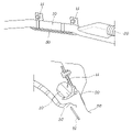
도 1a는 일반적인 커튼 에어백이 수납된 상태를 보여주는 도면이고, 도 1b는 일반적인 커튼 에어백이 전개된 상태를 보여주는 도면이며, 도 1c는 일반적인 커튼 에어백이 전개되는 과정을 보여주는 도면이다.1A is a view showing a state in which a general curtain airbag is stored, FIG. 1B is a view showing a general curtain airbag deployed state, and FIG. 1C is a diagram showing a general curtain airbag deployment process.
도 1a 내지 도 1c에 도시된 바와 같이 일반적인 커튼 에어백은 에어백쿠션(10)이 폴딩된 상태로 차량의 아웃보드(50), 헤드 라이너(52) 및 트림(51)으로 둘러싸이는 공간에 수납된다. 이때 에어백쿠션(10)은 다수의 마운팅 탭(11)에 의해 아웃보드(50)에 장착된다. 그리고, 에어백쿠션(10)에는 인플레이터(20)가 장착되어 인플레이터(20)의 작동에 의해 가스가 그 내부로 공급되면서 팽창하여 전개된다.As shown in FIGS. 1A to 1C , in a general curtain airbag, the
특히, 종래에는 에어백쿠션(10)이 전개되는 동안 트림(51)의 단부에 간섭되는 것을 방지하기 위하여 에어백쿠션(10)이 차량의 내측방향으로 전개되는 것을 가이드하는 램프(Ramp; 30)를 별도로 제작하여 에어백쿠션(10)과 아웃보드(50) 사이에 배치하였다.In particular, in the prior art, in order to prevent interference with the end of the
이렇게 종래의 커튼 에어백의 경우에는 트림(51)의 단부에 간섭되지 않고 에어백쿠션(10)이 전개되도록 하기 위하여 별도의 플라스틱 사출물인 램프(30)가 추가됨으로써 원가 상승 및 조립공수가 증가하는 문제가 있었다.As such, in the case of the conventional curtain airbag, a separate plastic
상기의 배경기술로서 설명된 내용은 본 발명에 대한 배경을 이해하기 위한 것일 뿐, 이 기술분야에서 통상의 지식을 가진 자에게 이미 알려진 종래기술에 해당함을 인정하는 것으로 받아들여져서는 안 될 것이다.The description of the above background art is only for understanding the background of the present invention, and should not be taken as an admission that it corresponds to the prior art already known to those skilled in the art.
본 발명은 별도의 플라스틱 사출물인 램프(Ramp) 부품을 생략하면서도 에어백 쿠션의 전개성을 향상시킬 수 있는 커튼 에어백을 제공한다.The present invention provides a curtain airbag capable of improving deployability of an airbag cushion while omitting a separate plastic injection-molded ramp part.
본 발명의 일 실시형태에 따른 커튼 에어백은 차량을 구성하는 필라의 상측에 차량의 전후방향을 따라 구비되어 팽창하면서 전개되는 메인 쿠션과; 상기 메인 쿠션의 상단부 전방영역에서 연결되어 차량의 후방쪽으로 연장되어 메인 쿠션과 함께 팽창되면서 차량의 내측 방향으로 밀어내는 가이드 쿠션을 포함한다.A curtain airbag according to an embodiment of the present invention includes a main cushion provided on the upper side of a pillar constituting a vehicle along the front-back direction of the vehicle and deployed while inflating; A guide cushion is connected to the front region of the upper end of the main cushion, extends toward the rear of the vehicle, and expands together with the main cushion to push toward the inside of the vehicle.
상기 가이드 쿠션은, 상기 메인 쿠션과 연결되어 차량의 아웃보드 방향으로 전개되어 메인 쿠션을 차량의 내측 방향으로 밀어내는 1차 전개영역과; 상기 1차 전개영역에서 연장되어 트림의 끝단부와 메인 챔버 사이로 전개되어 상기 메인 챔버를 트림의 끝단에 접촉되지 않도록 밀어내는 2차 전개영역으로 구분되는 것을 특징으로 한다.The guide cushion includes a primary deployment area connected to the main cushion and deployed in an outboard direction of the vehicle to push the main cushion inward of the vehicle; It is characterized in that it is divided into a secondary expansion area extending from the primary expansion area and extending between the end of the trim and the main chamber to push the main chamber away from contact with the end of the trim.
상기 가이드 쿠션은 1차 전개영역이 2차 전개영역보다 우선하여 전개되는 것을 특징으로 한다.The guide cushion is characterized in that the primary deployment area is deployed prior to the secondary deployment area.
상기 가이드 쿠션의 1차 전개영역에는 인플레이터가 장착되는 장착구가 형성되고, 상기 메인 쿠션과 상기 가이드 쿠션은 상기 장착구와 인접되는 부위에서 연통되어 상기 인플레이터에서 분출되는 가스가 상기 메인 쿠션과 가이드 쿠션의 1차 전개영역으로 분배되면서 유동되는 것을 특징으로 한다.A mounting hole in which an inflator is mounted is formed in the primary deployment area of the guide cushion, and the main cushion and the guide cushion communicate with each other at a portion adjacent to the mounting hole, so that the gas ejected from the inflator passes between the main cushion and the guide cushion. It is characterized in that it flows while being distributed to the primary deployment area.
상기 메인 쿠션과 가이드 쿠션이 연통되는 연통영역은 차량의 B필라가 위치되는 영역에 대응되는 영역이거나 그보다 차량의 전방쪽에 형성되는 것을 특징으로 한다.It is characterized in that the communication area where the main cushion and the guide cushion communicate is an area corresponding to the area where the B-pillar of the vehicle is located or formed toward the front of the vehicle.
상기 메인 쿠션은 롤 형태로 폴딩되고, 상기 가이드 쿠션은 상기 메인 쿠션의 외부를 감싸는 형상으로 메인 쿠션에 폴딩되는 것을 특징으로 한다.The main cushion is folded in a roll shape, and the guide cushion is folded to the main cushion in a shape surrounding the outside of the main cushion.
상기 가이드 쿠션의 단부는 상기 메인 쿠션을 향하는 안쪽 방향으로 접혀져 폴딩될 수 있다.An end of the guide cushion may be folded in an inward direction toward the main cushion.
상기 가이드 쿠션의 단부는 차량의 내측 방향으로 접혀져 폴딩될 수 있다.An end of the guide cushion may be folded toward the inside of the vehicle.
본 발명의 실시예에 따르면, 메인 쿠션에서 연장되는 가이드 쿠션을 마련하고, 가이드 쿠션에 의해 메인 쿠션의 팽창 초기에 메인 쿠션을 차량의 내측방향으로 밀어냄으로써, 메인 쿠션의 전개성을 향상시킬 수 있다.According to an embodiment of the present invention, the spreadability of the main cushion can be improved by providing a guide cushion extending from the main cushion and pushing the main cushion toward the inside of the vehicle at the initial stage of expansion of the main cushion by the guide cushion. .
특히, 종래와 같이 메인 쿠션의 전개방향으로 가이드 하는 별도의 플라스틱 사출물인 램프와 같은 부품이 불필요하기 때문에 커튼 에어백의 제조 원가를 절감시킬 수 있는 동시에 램프 조립을 위한 작업공수를 줄여 커튼 에어백의 생산성을 향상시킬 수 있다.In particular, since parts such as lamps, which are separate plastic injection moldings that guide the main cushion in the direction of deployment, are unnecessary, it is possible to reduce the manufacturing cost of curtain airbags and at the same time reduce the man-hours for assembling lamps, thereby increasing the productivity of curtain airbags. can improve
도 1a는 일반적인 커튼 에어백이 수납된 상태를 보여주는 도면이고,
도 1b는 일반적인 커튼 에어백이 전개된 상태를 보여주는 도면이며,
도 1c는 일반적인 커튼 에어백이 전개되는 과정을 보여주는 도면이고,
도 2는 본 발명의 일 실시예에 따른 커튼 에어백이 전개된 상태를 보여주는 도면이며,
도 3a는 본 발명의 일 실시예에 따른 커튼 에어백이 폴딩된 상태를 보여주는 도면이고,
도 3b 및 도 3c는 본 발명의 다른 실시예에 따른 커튼 에어백이 폴딩된 상태를 보여주는 도면이며,
도 4a 내지 도 4c는 본 발명의 일 실시예에 따른 커튼 에어백이 전개되는 과정을 보여주는 도면이다.1A is a view showing a state in which a general curtain airbag is stored;
1B is a view showing a state in which a general curtain airbag is deployed;
1C is a view showing the deployment process of a general curtain airbag;
2 is a view showing a deployed state of a curtain airbag according to an embodiment of the present invention;
3A is a view showing a folded state of a curtain airbag according to an embodiment of the present invention;
3b and 3c are views showing a folded state of a curtain airbag according to another embodiment of the present invention;
4A to 4C are diagrams illustrating a process of deploying a curtain airbag according to an embodiment of the present invention.
이하, 첨부된 도면을 참조하여 본 발명의 실시예를 더욱 상세히 설명하기로 한다. 그러나 본 발명은 이하에서 개시되는 실시예에 한정되는 것이 아니라 서로 다른 다양한 형태로 구현될 것이며, 단지 본 실시예들은 본 발명의 개시가 완전하도록 하며, 통상의 지식을 가진 자에게 발명의 범주를 완전하게 알려주기 위해 제공되는 것이다. 도면상에서 동일 부호는 동일한 요소를 지칭한다.Hereinafter, embodiments of the present invention will be described in more detail with reference to the accompanying drawings. However, the present invention is not limited to the embodiments disclosed below, but will be implemented in a variety of different forms, only these embodiments will complete the disclosure of the present invention, and will fully cover the scope of the invention to those skilled in the art. It is provided to inform you. Like reference numerals designate like elements in the drawings.
도 2는 본 발명의 일 실시예에 따른 커튼 에어백이 전개된 상태를 보여주는 도면이며, 도 3a는 본 발명의 일 실시예에 따른 커튼 에어백이 폴딩된 상태를 보여주는 도면이고, 도 3b 및 도 3c는 본 발명의 다른 실시예에 따른 커튼 에어백이 폴딩된 상태를 보여주는 도면이다.2 is a view showing a deployed state of the curtain airbag according to an embodiment of the present invention, FIG. 3A is a view showing a folded state of the curtain airbag according to an embodiment of the present invention, and FIGS. 3B and 3C are This is a view showing a folded state of a curtain airbag according to another embodiment of the present invention.
도면에 도시된 바와 본 발명의 일 실시예에 따른 커튼 에어백(100)은 차량의 전방 도어와 후방 도어의 상측에 차량의 전후방향으로 배치되어, 차량의 사고시에 시트에 앉은 탑승자의 측면을 보호하는 장치이다. 이를 위하여 커튼 에어백(100)은 차체의 측부를 구성하는 아웃보드(50), 헤드 라이너(52) 및 트림(51)으로 둘러싸이는 공간에 전후방향으로 길게 장착된다. 부연하자면, 차량이 A필라(미도시) 후단부터 B필라(PB)를 통과하여 C필라(PC)가 배치되는 위치까지 연장되어 길게 장착된다.As shown in the drawing, the
커튼 에어백(100)에 대하여 구체적으로 설명하자면, 본 발명의 일 실시예에 따른 커튼 에어백은 차량을 구성하는 필라의 상측에 차량의 전후방향을 따라 구비되어 팽창하면서 전개되는 메인 쿠션(110)과; 상기 메인 쿠션(110)의 상단부 전방영역에서 연결되어 차량의 후방쪽으로 연장되어 메인 쿠션(110)과 함께 팽창되면서 차량의 내측 방향으로 밀어내는 가이드 쿠션(120)을 포함한다.To describe the
메인 쿠션(110)은 탑승자의 측부에서 광범위하게 팽창되면서 전개되는 수단으로서, 평상시에는 롤 형상으로 말려진 형태로 차량의 아웃보드(50), 헤드 라이너(52) 및 트림(51)으로 둘러싸이는 공간에 차량의 길이 방향을 따라 길게 수납된다.The
이때 메인 쿠션(110)은 다수의 마운팅 탭(102)에 의해 차량의 아웃보드(50)에 장착된다.At this time, the
한편, 가이드 쿠션(120)은 메인 쿠션(110)의 전개시 메인 쿠션(110)이 트림(30)과 같은 주변 차체를 구성하는 부품에 간섭되지 않고 원활하게 팽창하면서 전개되도록 가이드 하는 수단으로서, 메인 쿠션(110)과 일체로 형성된다.On the other hand, the
예를 들어 가이드 쿠션(120)은 메인 쿠션(110)의 상단부 전방영역에서 가스의 흐름이 연통되도록 연결되어 차량의 후방쪽으로 연장된다. 그래서 메인 쿠션(110)과 함께 팽창되면서 팽창 초기에 메인 쿠션(110)을 차량의 내측 방향으로 밀어낸다.For example, the
구체적으로 가이드 쿠션(120)은 메인 쿠션(110)과 연결되어 차량의 아웃보드 방향으로 전개되어 메인 쿠션(110)을 차량의 내측 방향으로 밀어내는 1차 전개영역(121)과; 1차 전개영역(121)에서 연장되어 트림()의 끝단부와 메인 챔버() 사이로 전개되어 메인 챔버()를 트림()의 끝단에 접촉되지 않도록 밀어내는 2차 전개영역(122)으로 구분된다.Specifically, the
이때 가이드 쿠션(120)의 1차 전개영역(121)과 2차 전개영역(122)은 특정 수단에 의해 구분되는 것이 아니라 가이드 쿠션(120)이 전개되는 길이방향을 따라 구분되는데, 1차 전개영역(121)은 메인 쿠션(110)과 연결되는 부위, 즉 차량의 길이방향을 기준으로 전방측 영역에 해당되고, 2차 전개영역(122)은 1차 전개영역(121)에서 연장되는 후방측 영역에 해당된다.At this time, the
이렇게 가이드 쿠션(120)을 1차 전개영역(121)과 2차 전개영역(122)으로 구분함으로써, 가이드 쿠션(120)의 내부로 가스가 공급되어 전개되는 경우에 1차 전개영역(121)이 2차 전개영역(122)보다 우선하여 전개되는 것이 바람직하다.By dividing the
이를 위하여 가이드 쿠션(120)의 1차 전개영역(121)에는 인플레이터(20)가 장착되는 장착구(101)가 형성된다.To this end, a
그리고, 메인 쿠션(110)과 가이드 쿠션(120)은 장착구(101)와 인접되는 부위에서 연통된다. 그래서 인플레이터(20)에서 분출되는 가스가 메인 쿠션(110)과 가이드 쿠션(120)의 1차 전개영역(121)으로 분배되면서 유동된다.Then, the
이때 메인 쿠션(110)과 가이드 쿠션(120)이 연통되는 연통영역은 차량의 B필라(PB)가 위치되는 영역에 대응되는 영역이거나 그보다 차량의 전방쪽에 형성되는 것이 바람직하다. 그래서, 가이드 쿠션(120)이 1차 전개영역(121)에 이어서 2차 전개영역(122)이 순차적으로 팽창하면서 전개되도록 한다.At this time, the communication area where the
한편, 메인 쿠션(110)과 가이드 쿠션(120)은 2장의 원단을 겹친 상태로 원단의 가장자리를 봉제하여 형성한다. 따라서 메인 쿠션(110)과 가이드 쿠션(120)은 일체로 형성되지만, 메인 쿠션(110)과 가이드 쿠션(120)이 전개되는 순서 및 형상에 따라 봉제라인을 다양하게 구현하여 가스의 유동을 설정할 수 있다.On the other hand, the
본 실시예에서는 전술된 바와 같이 인플레이터(20)에서 분출되는 가스가 메인 쿠션(110)과 가이드 쿠션(120)으로 동시에 유동되도록 하여 메인 쿠션(110)의 전개 초기에 가이드 쿠션(120)의 1차 전개영역(121) 및 2차 전개영역(122)이 순차적으로 전개되도록 하는 것이 바람직하다.In this embodiment, as described above, the gas ejected from the inflator 20 flows simultaneously to the
한편, 메인 쿠션(110)과 가이드 쿠션(120)은 평상시에 롤 형태로 폴딩되어 수납된다.On the other hand, the
이때 도 3a에 도시된 바와 같이 가이드 쿠션(120)은 메인 쿠션(110)이 롤 형태로 폴딩된 외부를 감싸는 형상으로 메인 쿠션(110)에 폴딩되는 것이 바람직하다. 그래서, 메인 쿠션(110)과 가이드 쿠션(120)의 전개 초기에 상대적으로 메인 쿠션(110)보다 가이드 쿠션(120)이 먼저 전개되도록 하여 팽창되어 전개되는 가이드 쿠션(120)에 의해 메인 쿠션(110)이 차량의 내측방향으로 밀리도록 한다.At this time, as shown in FIG. 3A , the
다만, 가이드 쿠션(120)이 폴딩되는 형태는 이에 한정되지 않고, 다양한 방식으로 메인 쿠션(110)의 외부에 폴딩될 수 있다.However, the shape in which the
예를 들어 도 3b에 도시된 바와 같이 가이드 쿠션(120)의 단부가 메인 쿠션(110)을 향하는 안쪽 방향으로 접혀져 폴딩될 수 있다.For example, as shown in FIG. 3B , an end of the
또한, 도 3c에 도시된 바와 같이 가이드 쿠션(120)의 단부는 차량의 내측 방향으로 접혀져 폴딩될 수 있다.In addition, as shown in FIG. 3C , an end of the
다음으로 상기와 같이 구성되는 본 발명의 일 실시예에 따른 커튼 에어백이 전개되는 과정에 대하여 설명한다.Next, a process of deploying the curtain airbag according to an embodiment of the present invention configured as described above will be described.
도 4a 내지 도 4c는 본 발명의 일 실시예에 따른 커튼 에어백이 전개되는 과정을 보여주는 도면이다.4A to 4C are diagrams illustrating a process of deploying a curtain airbag according to an embodiment of the present invention.
도 4a는 평상시에 커튼 에어백이 수납되어 있는 상태를 보여주는 도면으로서, 메인 쿠션(110)과 가이드 쿠션(120)은 롤 형태로 함께 폴딩되어 아웃보드(50), 헤드 라이너(52) 및 트림(51)으로 둘러싸이는 공간에 수납된다.FIG. 4A is a view showing a state in which the curtain airbag is normally stored. The
이 상태에서 사고가 발생하는 경우에 인플레이터(20)가 작동되면서 가스가 분출되고, 분출되는 가스는 가이드 쿠션(120)의 1차 전개영역(121)을 팽창시키는 동시에 메인 쿠션(110)으로 유동되면서 메인 쿠션(110)을 팽창시키기 시작한다.In this state, when an accident occurs, gas is ejected while the inflator 20 operates, and the ejected gas inflates the
그러면, 도 4b와 같이 가이드 쿠션(120)의 1차 전개영역(121)이 먼저 팽창되어 전개된다. 이때 가이드 쿠션(120)의 1차 전개영역(121)은 메인 쿠션(110)과 차량의 아웃보드(50) 사이에서 팽창되면서 메인 쿠션(110)을 차량의 내측방향으로 미는 방향으로 전개된다.Then, as shown in FIG. 4B, the
한편, 가이드 쿠션(120)의 1차 전개영역(121)이 팽창되는 동시에 메인 쿠션(110)이 팽창되기 시작하고, 이때 메인 쿠션(110)의 외부에 폴딩된 가이드 쿠션(120)의 2차 전개영역(122)이 메인 쿠션(110)의 외부를 감싸고 있던 가이드 쿠션(120)의 2차 전개영역(122)이 펼쳐지면서 메인 쿠션(110)과 트림(51)의 사이에 위치된다.On the other hand, the
이 상태에서 인플레이터(20)로부터 가스가 계속되어 분출되면 도 4c와 같이 가이드 쿠션(120)의 2차 전개영역(122)까지 팽창되면서 전개되고, 전개된 가이드 쿠션(120)의 2차 전개영역(122)이 전개되는 메인 쿠션(110)을 트림(51)으로부터 멀어지게 밀어낸다.In this state, when gas is continuously ejected from the inflator 20, it is expanded and deployed to the
그런 다음 메인 쿠션(110)에 계속하여 가스가 공급되면서 메인 쿠션(110)이 완전히 전개된다.Then, the
이렇게 본 발명은 가이드 쿠션(120)의 1차 전개영역(121)과 2차 전개영역(122)의 순차적인 전개를 통하여 메인 쿠션(110)이 트림(51)과 간섭되지 않고 전개되도록 하여 전개성을 향상시키고, 특히 트림(51)을 회피하면서 메인 쿠션(110)을 전개시키기 위하여 종래의 램프(30)와 같은 별도의 부품이 불필요하게 됨으로써, 커튼 에어백(100)의 제조 원가를 절감시키는 동시에 램프 조립을 위한 작업공수를 생략할 수 있게 된다.In this way, the present invention allows the
본 발명을 첨부 도면과 전술된 바람직한 실시예를 참조하여 설명하였으나, 본 발명은 그에 한정되지 않으며, 후술되는 특허청구범위에 의해 한정된다. 따라서, 본 기술분야의 통상의 지식을 가진 자라면 후술되는 특허청구범위의 기술적 사상에서 벗어나지 않는 범위 내에서 본 발명을 다양하게 변형 및 수정할 수 있다.Although the present invention has been described with reference to the accompanying drawings and preferred embodiments described above, the present invention is not limited thereto, but is limited by the claims described below. Therefore, those skilled in the art can variously modify and modify the present invention within the scope not departing from the technical spirit of the claims described below.
10: 에어백 쿠션
11: 마운팅 탭
20: 인플레이터
30: 램프
50: 아웃보드
51: 트림
52: 헤드 라이너
100: 커튼 에어백
101: 장착구
102: 마운팅 탭
110: 메인 쿠션
120: 가이드 쿠션
121: 1차 전개영역
122: 1차 전개영역
PB: B필라
PC: C필라10: airbag cushion 11: mounting tab
20: inflator 30: lamp
50: outboard 51: trim
52: head liner 100: curtain airbag
101: mounting hole 102: mounting tab
110: main cushion 120: guide cushion
121: first deployment area 122: first deployment area
P B : B pillar P C : C pillar
Claims (8)
상기 메인 쿠션의 상단부 전방영역에서 연결되어 차량의 후방쪽으로 연장되어 메인 쿠션과 함께 팽창되면서 차량의 내측 방향으로 밀어내는 가이드 쿠션을 포함하는 커튼 에어백.
a main cushion provided on the upper side of a pillar constituting the vehicle along the front and rear directions of the vehicle and expanded and deployed;
A curtain airbag comprising a guide cushion that is connected at a front region of an upper end of the main cushion, extends toward the rear of the vehicle, and inflates with the main cushion to push toward the inside of the vehicle.
상기 가이드 쿠션은,
상기 메인 쿠션과 연결되어 차량의 아웃보드 방향으로 전개되어 메인 쿠션을 차량의 내측 방향으로 밀어내는 1차 전개영역과;
상기 1차 전개영역에서 연장되어 트림의 끝단부와 메인 챔버 사이로 전개되어 상기 메인 챔버를 트림의 끝단에 접촉되지 않도록 밀어내는 2차 전개영역으로 구분되는 것을 특징으로 하는 커튼 에어백.
The method of claim 1,
The guide cushion,
a primary deployment area connected to the main cushion and deployed in an outboard direction of the vehicle to push the main cushion inward of the vehicle;
A curtain airbag characterized in that it is divided into a secondary deployment area that extends from the primary deployment area and is deployed between the end of the trim and the main chamber to push the main chamber away from contact with the end of the trim.
상기 가이드 쿠션은 1차 전개영역이 2차 전개영역보다 우선하여 전개되는 것을 특징으로 하는 커튼 에어백.
The method of claim 2,
The curtain airbag according to claim 1 , wherein the guide cushion is deployed prior to a primary deployment area prior to a secondary deployment area.
상기 가이드 쿠션의 1차 전개영역에는 인플레이터가 장착되는 장착구가 형성되고,
상기 메인 쿠션과 상기 가이드 쿠션은 상기 장착구와 인접되는 부위에서 연통되어 상기 인플레이터에서 분출되는 가스가 상기 메인 쿠션과 가이드 쿠션의 1차 전개영역으로 분배되면서 유동되는 것을 특징으로 하는 커튼 에어백.
The method of claim 2,
A mounting hole in which an inflator is mounted is formed in the primary deployment area of the guide cushion,
The curtain airbag of claim 1 , wherein the main cushion and the guide cushion communicate with each other at a portion adjacent to the mounting hole so that gas ejected from the inflator flows while being distributed to a primary deployment area of the main cushion and the guide cushion.
상기 메인 쿠션과 가이드 쿠션이 연통되는 연통영역은 차량의 B필라가 위치되는 영역에 대응되는 영역이거나 그보다 차량의 전방쪽에 형성되는 것을 특징으로 하는 커튼 에어백.
The method of claim 4,
A curtain airbag according to claim 1 , wherein the communication area in which the main cushion and the guide cushion communicate is an area corresponding to the area where the B-pillar of the vehicle is located or formed toward the front of the vehicle.
상기 메인 쿠션은 롤 형태로 폴딩되고,
상기 가이드 쿠션은 상기 메인 쿠션의 외부를 감싸는 형상으로 메인 쿠션에 폴딩되는 것을 특징으로 하는 커튼 에어백.
The method of claim 1,
The main cushion is folded in a roll shape,
The curtain airbag, characterized in that the guide cushion is folded to the main cushion in a shape surrounding the outside of the main cushion.
상기 가이드 쿠션의 단부는 상기 메인 쿠션을 향하는 안쪽 방향으로 접혀져 폴딩되는 것을 특징으로 하는 커튼 에어백.
The method of claim 6,
Curtain airbags, characterized in that the ends of the guide cushion are folded inward toward the main cushion.
상기 가이드 쿠션의 단부는 차량의 내측 방향으로 접혀져 폴딩되는 것을 특징으로 하는 커튼 에어백.
The method of claim 6,
Curtain airbag, characterized in that the end of the guide cushion is folded in the vehicle inward direction is folded.
Priority Applications (4)
| Application Number | Priority Date | Filing Date | Title |
|---|---|---|---|
| KR1020210072218A KR20220163720A (en) | 2021-06-03 | 2021-06-03 | Curtain airbag |
| US17/662,398 US11858449B2 (en) | 2021-06-03 | 2022-05-06 | Curtain airbag |
| EP22175259.5A EP4098495B1 (en) | 2021-06-03 | 2022-05-24 | Curtain airbag |
| CN202221381116.0U CN217672543U (en) | 2021-06-03 | 2022-06-01 | Curtain airbag |
Applications Claiming Priority (1)
| Application Number | Priority Date | Filing Date | Title |
|---|---|---|---|
| KR1020210072218A KR20220163720A (en) | 2021-06-03 | 2021-06-03 | Curtain airbag |
Publications (1)
| Publication Number | Publication Date |
|---|---|
| KR20220163720A true KR20220163720A (en) | 2022-12-12 |
Family
ID=81850238
Family Applications (1)
| Application Number | Title | Priority Date | Filing Date |
|---|---|---|---|
| KR1020210072218A Pending KR20220163720A (en) | 2021-06-03 | 2021-06-03 | Curtain airbag |
Country Status (4)
| Country | Link |
|---|---|
| US (1) | US11858449B2 (en) |
| EP (1) | EP4098495B1 (en) |
| KR (1) | KR20220163720A (en) |
| CN (1) | CN217672543U (en) |
Families Citing this family (1)
| Publication number | Priority date | Publication date | Assignee | Title |
|---|---|---|---|---|
| KR20230127546A (en) * | 2022-02-25 | 2023-09-01 | 현대모비스 주식회사 | Curtain air bag |
Citations (1)
| Publication number | Priority date | Publication date | Assignee | Title |
|---|---|---|---|---|
| KR20210010049A (en) | 2019-07-19 | 2021-01-27 | 현대모비스 주식회사 | Curtain airbag apparatus |
Family Cites Families (24)
| Publication number | Priority date | Publication date | Assignee | Title |
|---|---|---|---|---|
| US6830262B2 (en) * | 2002-07-11 | 2004-12-14 | Autoliv Asp, Inc. | Inflatable airbag deployment guide |
| US7185914B2 (en) * | 2003-09-24 | 2007-03-06 | Autoliv Asp, Inc. | Inflatable curtain with pleats |
| DE102005002085B4 (en) * | 2004-03-17 | 2013-09-05 | TAKATA Aktiengesellschaft | Side air bag device |
| DE102005011676B4 (en) * | 2005-03-11 | 2012-04-19 | Autoliv Development Ab | Curtain airbag and motor vehicle |
| KR100656618B1 (en) * | 2005-11-21 | 2006-12-11 | 현대자동차주식회사 | Car Curtain Airbags |
| EP2043891B1 (en) * | 2006-07-17 | 2016-11-02 | Delphi Technologies, Inc. | Side curtain airbag with extended shoulder portion |
| DE102006061968A1 (en) * | 2006-12-21 | 2008-07-03 | Autoliv Development Ab | Curtain airbag |
| US8414014B2 (en) * | 2008-06-27 | 2013-04-09 | Autoliv Development Ab | Curtain airbag device for vehicle |
| US8408591B2 (en) * | 2009-04-17 | 2013-04-02 | Autoliv Asp, Inc. | Inflatable curtain airbags with expanded-volume lower portions for ejection mitigation |
| US8020888B2 (en) * | 2009-10-05 | 2011-09-20 | Autoliv Asp, Inc. | Vehicle curtain airbag |
| DE102009049764B4 (en) * | 2009-10-16 | 2016-02-18 | Autoliv Development Ab | An air bag assembly |
| JP5471953B2 (en) * | 2010-08-05 | 2014-04-16 | 豊田合成株式会社 | Head protection airbag device |
| US8613466B2 (en) * | 2011-05-10 | 2013-12-24 | Tk Holdings Inc. | Side-impact airbag module |
| JP6003720B2 (en) * | 2013-02-28 | 2016-10-05 | 豊田合成株式会社 | Head protection airbag device |
| JP6181443B2 (en) * | 2013-07-04 | 2017-08-16 | オートリブ ディベロップメント エービー | Curtain airbag device for vehicle |
| KR102605170B1 (en) * | 2016-06-22 | 2023-11-27 | 현대모비스 주식회사 | Curtain airbag apparatus |
| KR102083142B1 (en) * | 2016-09-05 | 2020-03-02 | 현대모비스 주식회사 | Curtain airbag apparatus |
| KR101867061B1 (en) * | 2016-10-05 | 2018-06-14 | 아우토리브 디벨롭먼트 아베 | Curtain airbag for vehicle |
| US9963102B1 (en) * | 2016-10-18 | 2018-05-08 | Autoliv Asp, Inc. | Top fill curtain airbags |
| KR102647194B1 (en) * | 2018-11-16 | 2024-03-13 | 현대자동차주식회사 | Curtain airbag for vehicle |
| KR102693553B1 (en) * | 2019-04-12 | 2024-08-08 | 현대모비스 주식회사 | Curtain airbag apparatus |
| KR102641419B1 (en) * | 2019-04-12 | 2024-02-27 | 현대모비스 주식회사 | Curtain air bag device |
| US11685332B2 (en) * | 2019-09-03 | 2023-06-27 | ZF Passive Safety Systems US Inc. | Vehicle airbag |
| KR102580397B1 (en) * | 2021-04-27 | 2023-09-20 | 현대모비스 주식회사 | Curtain air bag |
-
2021
- 2021-06-03 KR KR1020210072218A patent/KR20220163720A/en active Pending
-
2022
- 2022-05-06 US US17/662,398 patent/US11858449B2/en active Active
- 2022-05-24 EP EP22175259.5A patent/EP4098495B1/en active Active
- 2022-06-01 CN CN202221381116.0U patent/CN217672543U/en active Active
Patent Citations (1)
| Publication number | Priority date | Publication date | Assignee | Title |
|---|---|---|---|---|
| KR20210010049A (en) | 2019-07-19 | 2021-01-27 | 현대모비스 주식회사 | Curtain airbag apparatus |
Also Published As
| Publication number | Publication date |
|---|---|
| US11858449B2 (en) | 2024-01-02 |
| EP4098495A3 (en) | 2022-12-14 |
| US20220388469A1 (en) | 2022-12-08 |
| EP4098495B1 (en) | 2025-11-19 |
| EP4098495A2 (en) | 2022-12-07 |
| CN217672543U (en) | 2022-10-28 |
Similar Documents
| Publication | Publication Date | Title |
|---|---|---|
| CN102089189B (en) | Safety airbag device | |
| US8764053B1 (en) | Airbag assembly | |
| US20140239617A1 (en) | Airbag assembly | |
| US10322693B2 (en) | Vehicle airbag | |
| KR20160025370A (en) | Curtain Airbag Of Vehicle | |
| KR102580397B1 (en) | Curtain air bag | |
| JP2018114828A (en) | Curtain airbag, curtain airbag device, and manufacturing method of curtain airbag device | |
| US7234728B2 (en) | Airbag system | |
| EP3838689A1 (en) | Side airbag device | |
| JP3852412B2 (en) | Airbag device for vehicle | |
| JP2009286300A (en) | Head-restraining airbag system | |
| KR20190100764A (en) | Tether guide unit and curtain airbag apparatus with the same for vehicle | |
| WO2013146076A1 (en) | Head protection air bag system | |
| US20070241542A1 (en) | Air Bag Deployment Ramp | |
| JP4765561B2 (en) | Vehicle occupant restraint system | |
| CN217672543U (en) | Curtain airbag | |
| JP2001106014A (en) | Head protection airbag device | |
| KR20050049335A (en) | Side airbag and method of folding | |
| KR20110023462A (en) | Curtain airbag | |
| JP2001163161A (en) | Head protection airbag device | |
| KR100666624B1 (en) | Curtain airbag | |
| JP3881245B2 (en) | Airbag device for side impact of automobile | |
| KR20220163722A (en) | Curtain airbag apparatus | |
| KR20180037809A (en) | Curtain airbag for vehicle | |
| KR102366814B1 (en) | Curtain air bag and deployment method of curtain air bag |
Legal Events
| Date | Code | Title | Description |
|---|---|---|---|
| PA0109 | Patent application |
St.27 status event code: A-0-1-A10-A12-nap-PA0109 |
|
| PG1501 | Laying open of application |
St.27 status event code: A-1-1-Q10-Q12-nap-PG1501 |
|
| R18-X000 | Changes to party contact information recorded |
St.27 status event code: A-3-3-R10-R18-oth-X000 |
|
| A201 | Request for examination | ||
| PA0201 | Request for examination |
St.27 status event code: A-1-2-D10-D11-exm-PA0201 |
|
| D13 | Search requested |
Free format text: ST27 STATUS EVENT CODE: A-1-2-D10-D13-SRH-X000 (AS PROVIDED BY THE NATIONAL OFFICE) |
|
| D13-X000 | Search requested |
St.27 status event code: A-1-2-D10-D13-srh-X000 |
|
| D21 | Rejection of application intended |
Free format text: ST27 STATUS EVENT CODE: A-1-2-D10-D21-EXM-PE0902 (AS PROVIDED BY THE NATIONAL OFFICE) |
|
| PE0902 | Notice of grounds for rejection |
St.27 status event code: A-1-2-D10-D21-exm-PE0902 |
|
| E13 | Pre-grant limitation requested |
Free format text: ST27 STATUS EVENT CODE: A-2-3-E10-E13-LIM-X000 (AS PROVIDED BY THE NATIONAL OFFICE) |
|
| E13-X000 | Pre-grant limitation requested |
St.27 status event code: A-2-3-E10-E13-lim-X000 |
|
| P11 | Amendment of application requested |
Free format text: ST27 STATUS EVENT CODE: A-2-2-P10-P11-NAP-X000 (AS PROVIDED BY THE NATIONAL OFFICE) |
|
| P11-X000 | Amendment of application requested |
St.27 status event code: A-2-2-P10-P11-nap-X000 |
|
| P13 | Application amended |
Free format text: ST27 STATUS EVENT CODE: A-2-2-P10-P13-NAP-X000 (AS PROVIDED BY THE NATIONAL OFFICE) |
|
| P13-X000 | Application amended |
St.27 status event code: A-2-2-P10-P13-nap-X000 |