CN102089189B - Safety airbag device - Google Patents
Safety airbag device Download PDFInfo
- Publication number
- CN102089189B CN102089189B CN200980127259XA CN200980127259A CN102089189B CN 102089189 B CN102089189 B CN 102089189B CN 200980127259X A CN200980127259X A CN 200980127259XA CN 200980127259 A CN200980127259 A CN 200980127259A CN 102089189 B CN102089189 B CN 102089189B
- Authority
- CN
- China
- Prior art keywords
- airbag
- restricting member
- vehicle
- folded
- airbag device
- Prior art date
- Legal status (The legal status is an assumption and is not a legal conclusion. Google has not performed a legal analysis and makes no representation as to the accuracy of the status listed.)
- Expired - Fee Related
Links
Images


Classifications
-
- B—PERFORMING OPERATIONS; TRANSPORTING
- B60—VEHICLES IN GENERAL
- B60R—VEHICLES, VEHICLE FITTINGS, OR VEHICLE PARTS, NOT OTHERWISE PROVIDED FOR
- B60R21/00—Arrangements or fittings on vehicles for protecting or preventing injuries to occupants or pedestrians in case of accidents or other traffic risks
- B60R21/02—Occupant safety arrangements or fittings, e.g. crash pads
- B60R21/16—Inflatable occupant restraints or confinements designed to inflate upon impact or impending impact, e.g. air bags
- B60R21/23—Inflatable members
- B60R21/231—Inflatable members characterised by their shape, construction or spatial configuration
- B60R21/232—Curtain-type airbags deploying mainly in a vertical direction from their top edge
-
- B—PERFORMING OPERATIONS; TRANSPORTING
- B60—VEHICLES IN GENERAL
- B60R—VEHICLES, VEHICLE FITTINGS, OR VEHICLE PARTS, NOT OTHERWISE PROVIDED FOR
- B60R21/00—Arrangements or fittings on vehicles for protecting or preventing injuries to occupants or pedestrians in case of accidents or other traffic risks
- B60R21/02—Occupant safety arrangements or fittings, e.g. crash pads
- B60R21/16—Inflatable occupant restraints or confinements designed to inflate upon impact or impending impact, e.g. air bags
- B60R21/23—Inflatable members
- B60R21/231—Inflatable members characterised by their shape, construction or spatial configuration
- B60R21/2334—Expansion control features
-
- B—PERFORMING OPERATIONS; TRANSPORTING
- B60—VEHICLES IN GENERAL
- B60R—VEHICLES, VEHICLE FITTINGS, OR VEHICLE PARTS, NOT OTHERWISE PROVIDED FOR
- B60R21/00—Arrangements or fittings on vehicles for protecting or preventing injuries to occupants or pedestrians in case of accidents or other traffic risks
- B60R21/02—Occupant safety arrangements or fittings, e.g. crash pads
- B60R21/16—Inflatable occupant restraints or confinements designed to inflate upon impact or impending impact, e.g. air bags
- B60R21/23—Inflatable members
- B60R21/237—Inflatable members characterised by the way they are folded
-
- B—PERFORMING OPERATIONS; TRANSPORTING
- B60—VEHICLES IN GENERAL
- B60R—VEHICLES, VEHICLE FITTINGS, OR VEHICLE PARTS, NOT OTHERWISE PROVIDED FOR
- B60R21/00—Arrangements or fittings on vehicles for protecting or preventing injuries to occupants or pedestrians in case of accidents or other traffic risks
- B60R21/02—Occupant safety arrangements or fittings, e.g. crash pads
- B60R21/16—Inflatable occupant restraints or confinements designed to inflate upon impact or impending impact, e.g. air bags
- B60R2021/161—Inflatable occupant restraints or confinements designed to inflate upon impact or impending impact, e.g. air bags characterised by additional means for controlling deployment trajectory
-
- B—PERFORMING OPERATIONS; TRANSPORTING
- B60—VEHICLES IN GENERAL
- B60R—VEHICLES, VEHICLE FITTINGS, OR VEHICLE PARTS, NOT OTHERWISE PROVIDED FOR
- B60R21/00—Arrangements or fittings on vehicles for protecting or preventing injuries to occupants or pedestrians in case of accidents or other traffic risks
- B60R21/02—Occupant safety arrangements or fittings, e.g. crash pads
- B60R21/16—Inflatable occupant restraints or confinements designed to inflate upon impact or impending impact, e.g. air bags
- B60R21/20—Arrangements for storing inflatable members in their non-use or deflated condition; Arrangement or mounting of air bag modules or components
- B60R21/201—Packaging straps or envelopes for inflatable members
-
- B—PERFORMING OPERATIONS; TRANSPORTING
- B60—VEHICLES IN GENERAL
- B60R—VEHICLES, VEHICLE FITTINGS, OR VEHICLE PARTS, NOT OTHERWISE PROVIDED FOR
- B60R21/00—Arrangements or fittings on vehicles for protecting or preventing injuries to occupants or pedestrians in case of accidents or other traffic risks
- B60R21/02—Occupant safety arrangements or fittings, e.g. crash pads
- B60R21/16—Inflatable occupant restraints or confinements designed to inflate upon impact or impending impact, e.g. air bags
- B60R21/23—Inflatable members
- B60R21/231—Inflatable members characterised by their shape, construction or spatial configuration
- B60R21/233—Inflatable members characterised by their shape, construction or spatial configuration comprising a plurality of individual compartments; comprising two or more bag-like members, one within the other
Landscapes
- Engineering & Computer Science (AREA)
- Mechanical Engineering (AREA)
- Air Bags (AREA)
Abstract
本发明的课题是使包含折叠端部的安全气囊顺利地展开。本发明提供了一种在车辆内侧部呈窗帘状膨胀展开从而保护车内乘用人员的安全气囊装置,该装置具有产生膨胀气体的气体发生器和通过由上述气体发生器供给的气体膨胀展开的安全气囊。所述安全气囊在收容状态下被压缩成长尺状,该长尺状的安全气囊的端部沿长度方向折叠,由此形成没被折叠的安全气囊主体部和上述被折叠的端部。并且,所述装置还具有当该装置动作时对所述安全气囊的所述折叠端部向车外侧展开进行限制的限制构件。

The objective of this invention is to facilitate the smooth deployment of an airbag including a folded end. This invention provides an airbag device that expands in a curtain-like manner inside a vehicle to protect occupants. The device includes a gas generator that produces inflating gas and an airbag that expands and deploys using gas supplied by the gas generator. In its contained state, the airbag is compressed into a long, rectangular shape, with its end folded along its length, thereby forming an undisturbed airbag body and the folded end. Furthermore, the device includes a limiting member that restricts the folded end of the airbag from expanding outwards when the device is activated.
Description
技术领域 technical field
本发明涉及一种所谓的帘式安全气囊装置,其中安装在车室内侧部的安全气囊在车辆相撞时在车体侧壁和乘用人员之间展开从而保护乘用人员。The present invention relates to a so-called curtain airbag device in which an airbag installed inside a vehicle interior is deployed between a side wall of a vehicle body and a passenger to protect the passenger when a vehicle collides.
背景技术 Background technique
在专利文献1中公开了一种安全气囊装置,其中折叠起来的安全气囊袋体的后边缘部分向车辆的前后方向折叠,收容在车体的侧部上壁中。Patent Document 1 discloses an airbag device in which a rear edge portion of a folded airbag body is folded in the front-rear direction of a vehicle and accommodated in a side upper wall of a vehicle body.
专利文献1:特开2007-55545号公报Patent Document 1: JP-A-2007-55545
但是,在专利文献1所记载的安全气囊装置中,折叠起来的安全气囊的后端部不是向车内侧而是向车外侧展开,因此存在安全气囊陷进立柱装饰部件和立柱之间。这种情况会造成安全气囊无法顺利展开。However, in the airbag device described in Patent Document 1, the rear end portion of the folded airbag is deployed not toward the inside of the vehicle but toward the outside of the vehicle, so the airbag may be trapped between the pillar trim member and the pillar. This situation will prevent the airbag from deploying smoothly.
专利文献1:特开2007-55545号公报Patent Document 1: JP-A-2007-55545
发明内容 Contents of the invention
鉴于现有技术中存在的上述问题而作出了本发明,目的是提供一种能够使安全气囊顺利展开的结构。The present invention is made in view of the above-mentioned problems in the prior art, and its purpose is to provide a structure capable of smoothly deploying the airbag.
本发明提供了一种在车辆内的侧部中呈窗帘状膨胀展开从而保护该车辆中的乘用人员的安全气囊装置,该安全气囊装置具有产生膨胀气体的气体发生器以及通过上述的气体发生器所提供的气体膨胀展开的安全气囊。所述安全气囊在收容状态下被压缩成长尺状,所述长尺状的安全气囊的端部沿长度方向折叠,从而形成没被折叠的安全气囊主体部和所述被折叠的折叠端部。并且,该装置还具有当该装置工作时对所述安全气囊的折叠端部向车外侧展开进行限制的限制构件。The present invention provides an airbag device that inflates and deploys in a curtain-like manner in a side portion of a vehicle to protect occupants in the vehicle. The gas provided by the device inflates the deployed airbag. The airbag is compressed into a long shape in a housed state, and an end portion of the long airbag is folded in a longitudinal direction to form an unfolded airbag main body and the folded folded end. In addition, the device further includes a restricting member that restricts the deployment of the folded end portion of the airbag to the outside of the vehicle when the device is in operation.
本发明的效果Effect of the present invention
根据本发明的安全气囊装置,通过限制构件引导安全气囊的折叠端部不向车外侧而是向车内侧展开,从而避免了安全气囊陷进立柱装饰件和立柱之间。因此,能够使安全气囊顺利地展开。According to the airbag device of the present invention, the folding end of the airbag is guided not to the vehicle exterior but to the vehicle interior by the restricting member, thereby preventing the airbag from sinking between the pillar trim and the pillar. Therefore, the airbag can be smoothly deployed.
附图说明 Description of drawings
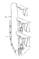
图1为具有本发明的实施例涉及的帘式安全气囊装置的车辆的车室部分的截面图。FIG. 1 is a cross-sectional view of a vehicle cabin portion of a vehicle having a curtain airbag device according to an embodiment of the present invention.
图2为表示在本发明的实施例涉及的帘式安全气囊装置中使用的安全气囊的结构的平面图。2 is a plan view showing the structure of an airbag used in the curtain airbag device according to the embodiment of the present invention.
图3为表示在本发明的实施例涉及的帘式安全气囊装置中使用的安全气囊的组装(折叠)工序的一部分的示意图。FIG. 3 is a schematic view showing a part of an assembling (folding) process of an airbag used in the curtain airbag device according to the embodiment of the present invention.
图4为表示在本发明的实施例涉及的帘式安全气囊装置中使用的限制构件的结构的示意图(立体图)。4 is a schematic diagram (perspective view) showing the structure of a restricting member used in the curtain airbag device according to the embodiment of the present invention.
图5为表示在本发明的实施例涉及的帘式安全气囊装置中使用的限制构件的结构的示意图(平面图)。5 is a schematic diagram (plan view) showing the structure of a restricting member used in the curtain airbag device according to the embodiment of the present invention.
图6为表示本发明的实施例涉及的帘式安全气囊装置的展开动作的示意图(截面图),显示了其收容状态(展开前的状态)。Fig. 6 is a schematic view (sectional view) showing the deployment operation of the curtain airbag device according to the embodiment of the present invention, showing its accommodated state (state before deployment).
图7为表示本发明的实施例涉及的帘式安全气囊装置的展开动作的示意图(截面图),显示了其展开初期的状态。Fig. 7 is a schematic diagram (sectional view) showing the deployment operation of the curtain airbag device according to the embodiment of the present invention, showing the initial state of deployment.
图8为表示本发明的实施例涉及的帘式安全气囊装置的展开动作的示意图(截面图),显示了展开中期的状态。8 is a schematic diagram (cross-sectional view) showing the deployment operation of the curtain airbag device according to the embodiment of the present invention, showing a state in the middle of deployment.
图9为表示本发明涉及的帘式安全气囊装置中采用的限制构件的一个变化方案的示意图。FIG. 9 is a schematic view showing a modification of the restricting member employed in the curtain airbag device according to the present invention.
附图标记说明Explanation of reference signs
10:帘式安全气囊装置10: Curtain airbag device
12:安全气囊12: Airbag
12a:安全气囊主体部12a: Airbag main body
12c:折叠端部12c: Folded ends
14:限制构件14: Limit member
14a:上侧端部14a: upper end
14b:下侧端部14b: lower end
30:保护构件30: Protection components
34:延伸区域34: Extended area
38:狭缝38: Slit
具体实施方式 Detailed ways
以下参考附图对本发明的实施方案进行说明。图1为具有本发明的实施例涉及的帘式安全气囊装置10的汽车的车室部分的截面图。如图1所示,在车室侧面的窗户上部设有被车内顶板覆盖的内护板。帘式安全气囊装置10用托架通过螺栓安装在内护板上。Embodiments of the present invention will be described below with reference to the drawings. FIG. 1 is a cross-sectional view of a vehicle compartment of an automobile provided with a
帘式安全气囊装置10具有:在收容状态下被设置在车窗上边缘的车内顶板覆盖、当动作时从车内顶板和内护板之间的间隙向下方膨胀展开从而保护车内的乘用人员的安全气囊12;和向安全气囊12供给膨胀气体的气体供给装置(图中未示出)。The
在车辆行驶过程中,一旦发生翻滚、侧面相撞、侧翻等事故时,车辆上设有的传感器感应到这样的异常振动,基于此信号向图中未示出的气体发生器(图中未示出)发出点火信号。在气体发生器内部具有接收来自传感器的点火信号后驱动气体发生器的推进器。通过气体发生器的动作,膨胀气体填充安全气囊12的内部,从而使安全气囊12推开车内顶板(弹飞)展开。展开的安全气囊12覆盖窗户的侧面,从而保护了车内的乘用人员。During the running of the vehicle, in the event of accidents such as rollover, side collision, rollover, etc., the sensor provided on the vehicle senses such abnormal vibration, based on this signal, the gas generator (not shown in the figure) is sent to the gas generator (not shown in the figure) shown) to send an ignition signal. Inside the gas generator, there is a thruster that drives the gas generator after receiving the ignition signal from the sensor. The inflation gas fills the inside of the
图2为表示安全气囊12的展开状态的平面示意图。安全气囊12可以采用多片(例如2片或3片)布重叠地进行缝合、粘合或熔合成袋状,或者用一整片织物形成袋状部分。FIG. 2 is a schematic plan view showing the deployed state of the
安全气囊12具有:将气体发生器(图中未示出)提供的气体导入内部的气体导入部24a,24b;多个设置在上边缘部分上的用于安装的接片22-1~22-9;由气体膨胀的多个腔室20;和将由气体导入部24a,24b导入的气体导入各个腔室20中的管道26。另外,虽然在本实施例中以使用两个气体发生器的情况作为示例,但显而易见的是在仅使用一个气体发生器的情况下本发明也是适用的。The
图3为表示在本实施例涉及的帘式安全气囊装置中使用的安全气囊的组装(折叠)工序的一部分的示意图。安全气囊12在收容时卷成卷状,形成近似棒状的卷状体,该卷状体的后端向下方折叠。在这种状态下,将未折叠的部分称为安全气囊主体部12a,将折叠的部分称为折叠端部12c。安全气囊12的压缩方法除了卷状也可采用蛇腹状等方法。并且,折叠端部12c的折叠方向不仅为下方,向车内侧或车外侧也能使本发明发挥效果,但向下的折叠的效果尤其好。Fig. 3 is a schematic diagram showing a part of the assembly (folding) process of the airbag used in the curtain airbag device according to the present embodiment. The
首先,将如图2所示的展开状态下的安全气囊12从下边缘部分一侧开始卷上来,形成如图3的上图所示的近似棒状的卷状体。然后,将布状的保护构件30在卷起来的安全气囊12的外周上从上侧卷起来。此时,将安全气囊12的气体发生器连接部24a、24b以及接片22-5~22-8插进保护构件30上设有的狭缝32。First, the
在保护构件30的后端部上设有限制安全气囊12的展开方向的展开限制部14。在图3的实施例中,展开限制部14形成为保护构件30的一部分,但它也可以是单独的构件。展开限制部14如图4所示,在卷成卷状的安全气囊12的安全气囊主体部12a与折叠端部12c之间卷成S字状。在图4中,附图标记12b表示安全气囊12的折叠部分。另外,以下对展开限制部14的结构进行详细的说明。A
当包含展开限制部14的保护构件30包围安全气囊12之后,将安全气囊12相对于图中未示出的托架用胶带固定。之后,将固定于托架上的安全气囊12相对于车体固定。After the
图5为展开限制构件14的结构的示意图(平面图)。如图4和图5所示,展开限制构件14在安全气囊装置动作时,对安全气囊12的折叠端部12c向车外侧展开进行限制。即是说,将折叠端部12c的展开方向导向车内侧。FIG. 5 is a schematic diagram (plan view) of the structure of the
限制构件14被卷成从安全气囊主体部12a的车内侧面穿过所述安全气囊主体部12a与折叠端部12c之间,并覆盖所述端部12c的车外侧面的S字状断面。限制构件14为在与安全气囊12的长度方向略成正交的方向上延伸的带状,可由除织物以外的树脂等材料制成。The restricting
限制构件14具有上侧端部14a和下侧端部14b,下侧端部14b从折叠端部12c的底部向车内侧延伸。如图3所示,限制构件14的一部分设置有狭缝,在安全气囊主体部12a上设置的接片22-8贯穿所述狭缝,从而连接了限制构件14与安全气囊12。The restricting
如图4和图5所示,限制构件14的中央附近形成能够比其它的部分更容易延伸的延伸区域34。在本实施例中,该延伸区域34通过狭缝38实现。狭缝38在平行的4个位置上形成。另外,狭缝38的形状、大小、个数等可以适当地变化。这样的延伸区域34,例如当限制构件14用树脂制成的情况下,可以使该部分为比其它部分的厚度小的薄壁区域。As shown in FIGS. 4 and 5 , near the center of the restricting
优选地,延伸区域34设置在与图2所示的安全气囊12的上边缘部分上设置的管道26相对应的位置上。当安全气囊装置发生动作,安全气囊12膨胀展开时,该安全气囊12内部的压力急剧上升,但由于延伸区域34的存在,能够避免发生堵住膨胀气流的事故(堵塞)。Preferably, the
然后,关于本实施例涉及的安全气囊12的展开动作,参照图6-图8进行说明。在安全气囊装置动作前的状态下,安全气囊12如图6所示收容在阻挡架(jump bracket)40内。之后,当由气体发生器产生的膨胀气体通过气体导入口24a、24b流入时,通过管道26使腔室20膨胀。此时,如图7所示,最初展开安全气囊主体部12a,然后通过限制构件14将安全气囊主体部12a向车辆外侧展开。Next, the deployment operation of the
当安全气囊主体部12a进一步展开时,如图8所示,由于限制构件14的存在,在安全气囊主体部12a的压力下将折叠端部12c导向车内侧。之后,折叠端部12c展开,从而使安全气囊12达到完全展开的状态。在这种情况下,由于折叠端部12c向车内侧展开,因此防止了安全气囊1When the airbag
2陷进立柱装饰件和立柱之间的事故,从而使安全气囊12能够顺利地展开。2 Accidents caught between the pillar trim and the pillar, so that the
图9为本发明涉及的帘式安全气囊装置所采用的限制构件的一个变化方案的示意图。如图9所示,作为限制构件,除了上述那样的1个宽幅的带状限制构件14之外,还可以采用1个窄幅的带状限制构件54或2个窄幅的限制构件64a,64b。并且,这样的限制构件54,64a,64b也可以与保护构件30一体成形。FIG. 9 is a schematic diagram of a modification of the restricting member employed in the curtain airbag device according to the present invention. As shown in FIG. 9, as the restricting member, in addition to the above-mentioned one wide belt-shaped restricting
以上对本发明的实施例进行了说明,但本发明并不局限于上述的实施例,在不脱离本专利的范围所记载的技术的思想的范围内,可以进行各种的设计的变化。显而易见,本发明涉及的帘式安全气囊装置除了3排座的SUV或轿车类型的车辆以外,也适用于2排座的乘用车类型的车辆等各种类型的车辆。The embodiments of the present invention have been described above, but the present invention is not limited to the above-mentioned embodiments, and various design changes are possible within the scope of the technical idea described in the scope of this patent. It is obvious that the curtain airbag device according to the present invention is applicable to various types of vehicles such as a 2-row passenger car, as well as a 3-row SUV or a sedan.
Claims (9)
Applications Claiming Priority (3)
| Application Number | Priority Date | Filing Date | Title |
|---|---|---|---|
| JP2008186355 | 2008-07-17 | ||
| JP2008-186355 | 2008-07-17 | ||
| PCT/JP2009/003155 WO2010007740A1 (en) | 2008-07-17 | 2009-07-07 | Airbag device |
Publications (2)
| Publication Number | Publication Date |
|---|---|
| CN102089189A CN102089189A (en) | 2011-06-08 |
| CN102089189B true CN102089189B (en) | 2013-03-13 |
Family
ID=41550152
Family Applications (1)
| Application Number | Title | Priority Date | Filing Date |
|---|---|---|---|
| CN200980127259XA Expired - Fee Related CN102089189B (en) | 2008-07-17 | 2009-07-07 | Safety airbag device |
Country Status (4)
| Country | Link |
|---|---|
| US (1) | US8414020B2 (en) |
| JP (1) | JP5149383B2 (en) |
| CN (1) | CN102089189B (en) |
| WO (1) | WO2010007740A1 (en) |
Families Citing this family (31)
| Publication number | Priority date | Publication date | Assignee | Title |
|---|---|---|---|---|
| JP5522383B2 (en) * | 2010-03-31 | 2014-06-18 | マツダ株式会社 | Vehicle interior structure |
| JP5529968B2 (en) * | 2010-08-06 | 2014-06-25 | オートリブ ディベロップメント エービー | Curtain airbag |
| JP5480179B2 (en) * | 2011-02-18 | 2014-04-23 | オートリブ ディベロップメント エービー | Curtain airbag device |
| DE102011005549A1 (en) * | 2011-03-15 | 2011-07-21 | Takata-Petri Ag, 63743 | Side gas bag for vehicle occupant restraint system of motor vehicle, has inflatable chamber comprising head protection region and overlapping region and tapered from head protection region towards overlapping region |
| WO2012147490A1 (en) * | 2011-04-28 | 2012-11-01 | オートリブ ディベロップメント エービー | Curtain airbag device |
| JP5380493B2 (en) * | 2011-06-09 | 2014-01-08 | 本田技研工業株式会社 | Side curtain airbag |
| DE102011106794B4 (en) * | 2011-07-06 | 2018-08-16 | Autoliv Development Ab | Curtain airbag for a motor vehicle |
| US8500162B2 (en) * | 2011-12-22 | 2013-08-06 | Autoliv Asp, Inc. | Inflatable curtain airbag with an integrated pillar guide |
| JP2013203171A (en) * | 2012-03-28 | 2013-10-07 | Nippon Plast Co Ltd | Airbag |
| JP2014014437A (en) * | 2012-07-06 | 2014-01-30 | Panasonic Corp | Air bag integrally molded from resin material and massage chair including air bag |
| JP5846643B2 (en) * | 2012-08-31 | 2016-01-20 | トヨタ車体株式会社 | Curtain shield airbag mounting structure |
| JP5804528B2 (en) * | 2013-03-12 | 2015-11-04 | 株式会社豊田自動織機 | Curtain airbag device |
| JP6067489B2 (en) * | 2013-06-10 | 2017-01-25 | 豊田合成株式会社 | Side airbag device |
| US9278661B2 (en) * | 2013-10-29 | 2016-03-08 | Nissan North America, Inc. | Vehicle airbag assembly |
| EP2910434B1 (en) * | 2014-02-20 | 2017-04-12 | Dalphi Metal España, S.A. | Mounting envelope |
| US9637081B2 (en) * | 2014-07-14 | 2017-05-02 | Ford Global Technologies, Llc | Curtain airbag with protective sheet |
| JP6325468B2 (en) * | 2015-02-09 | 2018-05-16 | オートリブ ディベロップメント エービー | Curtain airbag |
| US10654438B2 (en) * | 2015-06-05 | 2020-05-19 | Autoliv Development Ab | Curtain airbag device |
| JP2017087864A (en) * | 2015-11-05 | 2017-05-25 | 豊田合成株式会社 | Head protection airbag |
| JP6583095B2 (en) * | 2016-03-29 | 2019-10-02 | 豊田合成株式会社 | Folded body of the head protection airbag |
| KR101867061B1 (en) * | 2016-10-05 | 2018-06-14 | 아우토리브 디벨롭먼트 아베 | Curtain airbag for vehicle |
| DE102017101092A1 (en) * | 2017-01-20 | 2018-07-26 | Trw Automotive Gmbh | Method for assembling a gas bag |
| CN107804269B (en) * | 2017-09-30 | 2019-06-04 | 安徽江淮汽车集团股份有限公司 | A kind of side curtain airbag generating device |
| DE102018208941B4 (en) * | 2018-06-06 | 2023-05-25 | Joyson Safety Systems Germany Gmbh | Gas bag arrangement for a vehicle occupant restraint system of a motor vehicle |
| DE102018115062A1 (en) * | 2018-06-22 | 2019-12-24 | Dalphi Metal Espana, S.A. | GAS BAG UNIT, IN PARTICULAR HEAD SIDE GAS BAG UNIT |
| US10807558B2 (en) * | 2018-11-02 | 2020-10-20 | Joyson Safety Systems Acquisition Llc | Side impact airbag module |
| KR102693553B1 (en) * | 2019-04-12 | 2024-08-08 | 현대모비스 주식회사 | Curtain airbag apparatus |
| EP3808610B1 (en) * | 2019-10-18 | 2021-11-03 | Autoliv Development AB | Airbag device |
| JP2021146865A (en) * | 2020-03-18 | 2021-09-27 | 本田技研工業株式会社 | Airbag device |
| US11345302B2 (en) * | 2020-07-27 | 2022-05-31 | ZF Passive Safety Systems US Inc. | Curtain airbag with integral airbag wrap |
| US20230182675A1 (en) * | 2021-12-14 | 2023-06-15 | Autoliv Asp, Inc. | Inflatable curtain airbag with bi-roll package state |
Citations (4)
| Publication number | Priority date | Publication date | Assignee | Title |
|---|---|---|---|---|
| CN1390723A (en) * | 2001-06-11 | 2003-01-15 | 本田技研工业株式会社 | Constrain systems of passenger |
| CN1438141A (en) * | 2002-02-12 | 2003-08-27 | 高田株式会社 | Curtain-type air-bag |
| JP2006248420A (en) * | 2005-03-11 | 2006-09-21 | Honda Motor Co Ltd | Airbag device |
| JP2007015760A (en) * | 2005-07-06 | 2007-01-25 | Yoshiyuki Goto | Binder |
Family Cites Families (9)
| Publication number | Priority date | Publication date | Assignee | Title |
|---|---|---|---|---|
| JPS6146824U (en) * | 1984-08-30 | 1986-03-28 | 有限会社 芝製作所 | Holder for bundling wires |
| US6626456B2 (en) * | 2001-06-26 | 2003-09-30 | Autoliv Asp, Inc. | Apparatus and method for inflatable curtain wrap |
| JP3914425B2 (en) | 2001-12-04 | 2007-05-16 | 日本プラスト株式会社 | Airbag |
| JP3935032B2 (en) | 2002-09-06 | 2007-06-20 | 本田技研工業株式会社 | Crew restraint system |
| JP4123048B2 (en) * | 2003-05-15 | 2008-07-23 | トヨタ車体株式会社 | Head protection airbag device |
| US7380815B2 (en) * | 2004-04-05 | 2008-06-03 | Autoliv Asp, Inc. | Lower side piller passenger inflatable safety restraint assembly |
| JP4665668B2 (en) | 2005-08-26 | 2011-04-06 | トヨタ自動車株式会社 | Head protection airbag device |
| JP4765561B2 (en) * | 2005-11-04 | 2011-09-07 | タカタ株式会社 | Vehicle occupant restraint system |
| JP5040288B2 (en) * | 2006-07-28 | 2012-10-03 | 豊田合成株式会社 | Airbag device |
-
2009
- 2009-07-07 WO PCT/JP2009/003155 patent/WO2010007740A1/en not_active Ceased
- 2009-07-07 JP JP2010520753A patent/JP5149383B2/en active Active
- 2009-07-07 US US13/054,424 patent/US8414020B2/en not_active Expired - Fee Related
- 2009-07-07 CN CN200980127259XA patent/CN102089189B/en not_active Expired - Fee Related
Patent Citations (4)
| Publication number | Priority date | Publication date | Assignee | Title |
|---|---|---|---|---|
| CN1390723A (en) * | 2001-06-11 | 2003-01-15 | 本田技研工业株式会社 | Constrain systems of passenger |
| CN1438141A (en) * | 2002-02-12 | 2003-08-27 | 高田株式会社 | Curtain-type air-bag |
| JP2006248420A (en) * | 2005-03-11 | 2006-09-21 | Honda Motor Co Ltd | Airbag device |
| JP2007015760A (en) * | 2005-07-06 | 2007-01-25 | Yoshiyuki Goto | Binder |
Also Published As
| Publication number | Publication date |
|---|---|
| JPWO2010007740A1 (en) | 2012-01-05 |
| CN102089189A (en) | 2011-06-08 |
| US20110127755A1 (en) | 2011-06-02 |
| US8414020B2 (en) | 2013-04-09 |
| WO2010007740A1 (en) | 2010-01-21 |
| JP5149383B2 (en) | 2013-02-20 |
Similar Documents
| Publication | Publication Date | Title |
|---|---|---|
| CN102089189B (en) | Safety airbag device | |
| US9266494B2 (en) | Fold over design for small overlap | |
| US9027954B2 (en) | Airbag device | |
| CN102300750B (en) | Car head protection airbag device | |
| US7992892B2 (en) | Inflatable ramp for inflatable curtain side impact restraint | |
| CN103619657B (en) | Air bag device | |
| KR101708223B1 (en) | Side curtain airbag for vehicle | |
| JP4221017B2 (en) | Head protection airbag device | |
| WO2014132513A1 (en) | Head protection air bag device and method for folding air bag | |
| KR20160025370A (en) | Curtain Airbag Of Vehicle | |
| KR102005748B1 (en) | Curtain airbag of vehicle | |
| JP5312474B2 (en) | Side airbag device and method for manufacturing side airbag device | |
| JP2008290471A (en) | Curtain airbag device | |
| JP4432699B2 (en) | Airbag device | |
| JP4765561B2 (en) | Vehicle occupant restraint system | |
| JP2000006750A (en) | Head protection airbag device for front and rear seats | |
| WO2012090637A1 (en) | Curtain airbag device | |
| JP7368210B2 (en) | Airbag and its folding method | |
| JP4486965B2 (en) | Curtain airbag device | |
| JP4721987B2 (en) | Head protection airbag device | |
| KR102366814B1 (en) | Curtain air bag and deployment method of curtain air bag | |
| KR102557710B1 (en) | Airbag unit of vehicle | |
| JP7298528B2 (en) | Head protection airbag device | |
| JP5843432B2 (en) | Curtain airbag device | |
| JP5595732B2 (en) | Airbag device |
Legal Events
| Date | Code | Title | Description |
|---|---|---|---|
| C06 | Publication | ||
| PB01 | Publication | ||
| C10 | Entry into substantive examination | ||
| SE01 | Entry into force of request for substantive examination | ||
| C14 | Grant of patent or utility model | ||
| GR01 | Patent grant | ||
| CF01 | Termination of patent right due to non-payment of annual fee | ||
| CF01 | Termination of patent right due to non-payment of annual fee |
Granted publication date: 20130313 |