KR20200000189A - apparatus of the shaft type roller gear cam - Google Patents
apparatus of the shaft type roller gear cam Download PDFInfo
- Publication number
- KR20200000189A KR20200000189A KR1020180072167A KR20180072167A KR20200000189A KR 20200000189 A KR20200000189 A KR 20200000189A KR 1020180072167 A KR1020180072167 A KR 1020180072167A KR 20180072167 A KR20180072167 A KR 20180072167A KR 20200000189 A KR20200000189 A KR 20200000189A
- Authority
- KR
- South Korea
- Prior art keywords
- roller gear
- gear cam
- rotary table
- main
- axial roller
- Prior art date
- Legal status (The legal status is an assumption and is not a legal conclusion. Google has not performed a legal analysis and makes no representation as to the accuracy of the status listed.)
- Ceased
Links
Images


Classifications
-
- B—PERFORMING OPERATIONS; TRANSPORTING
- B23—MACHINE TOOLS; METAL-WORKING NOT OTHERWISE PROVIDED FOR
- B23F—MAKING GEARS OR TOOTHED RACKS
- B23F13/00—Making worms by methods essentially requiring the use of machines of the gear-cutting type
- B23F13/02—Making worms of cylindrical shape
-
- B—PERFORMING OPERATIONS; TRANSPORTING
- B23—MACHINE TOOLS; METAL-WORKING NOT OTHERWISE PROVIDED FOR
- B23C—MILLING
- B23C1/00—Milling machines not designed for particular work or special operations
- B23C1/02—Milling machines not designed for particular work or special operations with one horizontal working-spindle
-
- B—PERFORMING OPERATIONS; TRANSPORTING
- B23—MACHINE TOOLS; METAL-WORKING NOT OTHERWISE PROVIDED FOR
- B23F—MAKING GEARS OR TOOTHED RACKS
- B23F21/00—Tools specially adapted for use in machines for manufacturing gear teeth
- B23F21/12—Milling tools
-
- B—PERFORMING OPERATIONS; TRANSPORTING
- B23—MACHINE TOOLS; METAL-WORKING NOT OTHERWISE PROVIDED FOR
- B23F—MAKING GEARS OR TOOTHED RACKS
- B23F23/00—Accessories or equipment combined with or arranged in, or specially designed to form part of, gear-cutting machines
- B23F23/003—Generating mechanisms
-
- B—PERFORMING OPERATIONS; TRANSPORTING
- B23—MACHINE TOOLS; METAL-WORKING NOT OTHERWISE PROVIDED FOR
- B23F—MAKING GEARS OR TOOTHED RACKS
- B23F9/00—Making gears having teeth curved in their longitudinal direction
- B23F9/08—Making gears having teeth curved in their longitudinal direction by milling, e.g. with helicoidal hob
Landscapes
- Engineering & Computer Science (AREA)
- Mechanical Engineering (AREA)
- Turning (AREA)
Abstract
본 발명의 축형롤러기어캠 가공장치는 수평형 밀링머신 본체부에 설치되는 메인회전테이블과, 상기 메인회전터에블의 일측에 설치되는 회전테이블과, 상기 회전테이블의 대향되는 측에 설치되는 회전테이블에 의해 회전되는 공작물을 메인테이블의 상면과 수평상태로 지지하기 위한 심압대와,
상기 공작물의 중심축과 동일한 높이로 위치할 수 있는 수평으로 설치되며 가공공구가 설치된 주축을 포함한 가공유닛을 포함한다. An axial roller gear cam processing apparatus of the present invention includes a main rotary table installed on a main body of a horizontal milling machine, a rotary table installed on one side of the main rotary tab, and a rotation provided on an opposite side of the rotary table. Tailstock for supporting the workpiece rotated by the table in a horizontal state with the upper surface of the main table,
It includes a machining unit is installed horizontally and can be positioned at the same height as the central axis of the workpiece, the machining unit including a main shaft is installed.

Description
본 발명은 축형롤러기어캠 가공장치에 관한 것으로, 더 상세하게는 구조가 상대적으로 간단하고, 가공프로그램의 변경 없이 가공유닛의 옵셋기능만으로 추가가공량을 조정할 수 있는 축형롤러기어캠의 가공장치에 관한 것이다. The present invention, more specifically, the structure is relatively simple, and the machining of the axial roller gear cam that added to adjust the gongryang without changing the part program to only offset functions of the processing units coming on the axial roller gear cam processing device Relates to a device.
일반적으로 각종의 절삭 가공방법 또는 비절삭 가공방법으로 금속 또는 비금속의 소재를 적당한 공구를 사용하여 형상을 가공하든가 또는 반 소재에 더욱 정밀한 가공을 할 목적으로 사용하는 다양한 공작기계가 사용되고 있다. In general, various machine tools are used in various cutting or non-cutting methods for the purpose of processing a shape of a metal or non-metal material using a suitable tool or for more precise machining on a semi-material.
상기한 공작기계중에서 가공과정에서 칩이 발생하는 공작기계를 절삭가공 공작기계라고 하고, 가공과정에서 칩이 발생하지 않는 비절삭 공작기계를 소성가공기계라고 한다. 상기한 절삭공작기계에는 선반(lathe), 밀링기, 머시닝센터(machining center), 드릴링기, 보링기, 연삭기, 기어가공기, 특수가공기 등이 있고, 상기한 금속성형기계에는 기계식 프레스, 유압식 프레스, 절단절곡기, 단조기, 인발기 등이 있다. Among the machine tools described above, a machine tool in which chips are generated in a machining process is called a cutting machine tool, and a non-cut machine tool in which chips are not generated in a machining process is called a plastic machine. The above cutting machine tools include lathes, milling machines, machining centers, drilling machines, boring machines, grinding machines, gear cutters, special processing machines, and the like. Bending machine, forging machine, drawing machine and the like.
한편, 축형롤러캠, 즉, 도 1 및 도 2에 도시된 바와 같이 축에 의해 지지된 캠본체(110)의 외주면에 형성된 나선형 치(120)의 골(130)을 연결하는 선(200)이 호형 또는 만곡된 형상으로 형성된 것으로, 캠을 구성하는 부 즉, 치가 형성된 부위의 직경(D1)이 캠을 구성하는 부위의 길이(L1) 보다 작게 형성된 구성을 가진다.
그리고 도 3에 도시된 바와 같이 드럼형 롤러기어캠은 디스크 형상으로 캠(210)을 구성하는 부분의 직경(D2)이 캠을 구성하는 부위의 길이(L2) 보다 크게 형성된 형성된 구성을 가진다. Meanwhile, the
상기 롤러기어캠들중 축형롤러기어캠을 가공하기 위해서는 상대적으로 고가의 전용가공장치 또는 CNC 선반을 베이스로 한 5~6축의 복합가공기 등이 이용되는데, 이는 가공에 따른 원가 상승 및 조작의 복잡성, 강성부족의 원인이된다. Among the roller gear cams, in order to process the axial roller gear cam, a relatively expensive dedicated processing device or a 5 to 6-axis multi-task machine based on a CNC lathe is used, which increases cost and complexity of operation. Cause of lack of rigidity.
대한민국 특허등록 제 10-0385893호에는 4축 머시닝센터에서 드럼형 롤러기어캠 가공방법이 게시되어 있다. 범용 3축 머시닝센터에 부가축을 장착하여 드럼형 롤러기어캠을 가공하기 위한 것으로, 공구가 롤러의 경로를 따라서 가공될 수 있도록 터렛의 중심을 축으로 회전하여 생기는 각 롤러의 경로를 롤러기어캠의 회전과 공구의 이송값으로 각각 변환하여 엔씨코드(NC-Code)를 생성하여 드럼형 롤러기어캠을 가공한다. Korean Patent Registration No. 10-0385893 discloses a drum-type roller gear cam processing method in a four-axis machining center. It is to process drum type roller gear cam by attaching additional axis to general purpose 3-axis machining center, and the path of each roller that is generated by rotating the center of turret to the axis so that the tool can be processed along the path of roller Drum type by generating NC code by converting to rotation and feed value of tool respectively Machine the roller gear cam.
이러한 종래 드럼형 롤러기어캠 가공방법으로는 상기 축형롤러기어캠의 가공이 불가능하다. 뿐만 아니라 CNC 선반을 베이스로 한 5~6축의 복합가공기는 절삭(연마)공구가 고정된 주축(Main Spindle)이 회전이송축과 같이 이송(이동)하므로 옵셋(Offset)기능을 사용하기 위해서는 NC-Code를 새롭게 생성해야 하는 문제점이 있으며, 강성을 높이기 위한 증가 등의 요인이 발생한다. In the conventional drum-type roller gear cam processing method, it is impossible to process the axial roller gear cam. In addition, the 5- to 6-axis multi-task machine based on CNC lathes moves the main spindle to which the cutting tool is fixed. There is a problem of newly generating code, and factors such as increase to increase rigidity occur.
본 발명은 상기 문제점을 해결하기 위한 것으로, 수평형 밀링머신을 이용하여 축형롤러기어캠을 가공할 수 있도록 함으로써 제작원가를 줄일 수 있는, 축형롤러기어캠 가공장치를 제공함에 그 목적이 있다. An object of the present invention is to provide an axial roller gear cam processing apparatus that can reduce the manufacturing cost by allowing the axial roller gear cam to be processed using a horizontal milling machine.
본 발명의 다른 목적은 축형롤러캠의 가공 시 가공공구가 장착된 주축의 직선이송축 한축의 옵셋 조정만으로 가공량의 조절이 용이한 축형롤러기어캠 가공장치를 제공함에 있다. Another object of the present invention is to provide an axial roller gear cam processing apparatus that is easy to adjust the amount of processing only by adjusting the offset of one axis of the linear feed axis of the spindle equipped with the processing tool when machining the axial roller cam.
상기 기술적 과제를 해결하기 위한 본 발명의 축형롤러기어캠 가공장치는 An axial roller gear cam processing apparatus of the present invention for solving the above technical problem is
본체부에 설치되는 메인회전테이블과, 상기 메인회전터에블의 일측에 설치되는 회전테이블과, 상기 회전테이블의 대향되는 측에 설치되는 회전테이블에 의해 회전되는 공작물을 메인테이블의 상면과 수평상태로 지지하기 위한 심압대와, The workpiece rotated by the main rotary table installed on the main body, the rotary table provided on one side of the main rotary table, and the rotary table provided on the opposite side of the rotary table are horizontally aligned with the upper surface of the main table. Tailstock to support
상기 공작물을 가공할 수 있도록 수평으로 설치되며 가공공구가 설치된 주축을 포함한 가공유닛을 포함한 것을 특징으로 한다. It is installed horizontally so as to process the workpiece, characterized in that it comprises a processing unit including a main shaft is installed a processing tool.
본 발명에 있어서, 메인테이블에 설치되는 공작물을 지지하는 회전테이블에는 공작물을 파지하기 위한 척이 설치될 수 있다. In the present invention, a chuck for gripping the workpiece may be installed on the rotary table for supporting the workpiece installed on the main table.
본 발명에 따른 축형롤러기어캠 가공장치는 축형롤러기어캠의 가공에 따른 가공원가를 줄일 수 있으며, 수평형 밀링을 이용하여 구현할 수 있으므로 축형롤러기어캠 가공장치의 원가를 줄일 수 있다. The axial roller gear cam processing apparatus according to the present invention can reduce the processing cost according to the processing of the axial roller gear cam, and can be implemented by using horizontal milling can reduce the cost of the axial roller gear cam processing apparatus.
그리고 본 발명의 축형롤러기어캠 가공장치는 소정의 각도로 회전되는 메인회전테이블에 설치되어 회전테이블에 축형롤러기어캠의 가공을 위한 공작물을 수평한 상태로 지지하고 있으므로 축형롤러기어캠의 가공량의 조정이 가공를 위한 공구의 옵셋 조정만으로 가능하다 And the axial roller gear cam processing apparatus of the present invention is installed on the main rotary table rotated at a predetermined angle to support the workpiece for the machining of the axial roller gear cam on the rotary table in a horizontal state, so the amount of processing of the axial roller gear cam Can be adjusted simply by adjusting the offset of the tool for machining.
도 1은 축형롤러기어캠의 사시도,
도 2는 축형롤러기어캠의 평면도
도 3은 드럼형롤러기어캠의 정면도,
도 4은 본 발명에 따른 축형롤러기어캠 가공장치의 사시도,
도 5는 도 4에 도시된 본 발명에 따른 축형롤러기어캠 가공장치에 의해 축형롤러기어캠이 가공되는 상태를 나타내 보인 평면도.
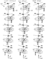
도 6은 주축에 설치된 가공공구에 의해 축형 롤러기어캠이 가공되는 상태 및 직선이송축을 이용한 편리한 Offset기능을 나타내 보인 도면 1 is a perspective view of an axial roller gear cam,
2 is a plan view of the axial roller gear cam
3 is a front view of the drum-type roller gear cam,
Figure 4 is a perspective view of the axial roller gear cam processing apparatus according to the present invention,
5 is a plan view showing a state in which the axial roller gear cam is processed by the axial roller gear cam processing apparatus according to the present invention shown in FIG.
6 is a view showing a state in which an axial roller gear cam is processed by a processing tool installed on a main shaft and a convenient offset function using a linear feed shaft.
본 발명에 따른 축형롤러기어캠 가공장치는 수평형 밀링머신을 이용한 것으로, 일 실시 예들을 도 4 내지 도 6에 나타내 보였다.The axial roller gear cam processing apparatus according to the present invention uses a horizontal milling machine, and one embodiment is shown in FIGS. 4 to 6.
도 3내지 도 4을 참조하면, 본 발명에 따른 축형롤러기어캠 가공장치(10)는 도 1 및 도 2에 도시된 바와 같은 축형롤러기어캠(100) 즉, 캠을 구성하는 부분의 직경(D1)이 캠을 구성하는 부분의 길이(L1) 보다 길며 캠기어본체의 외주면에 형성된 골(130)을 연결하는 선(200)이 원 또는 호를 이루는 축형롤러기어캠(100)을 가공하기 위한 가공유닛(20)인 수평밀링머신(horizontal milling machine)의 가공공구(22)가 장착된 주축(21)과 평행한 상면을 가지며, 제1구동부(미도시)에 의해 정역회전이 가능한 메인회전테이블(30)을 구비한다. 그리고 상기 메인회전테이블(30)에는 상기 축형롤러기어캠(100)의 일측을 파지한 상태에서 회전시키기 위한 회전테이블(40)이 장착되고, 이와 대응되는 측에는 축형롤러기어캠(100)의 타측을 파지하기 위한 심압대(50)가 설치된다. 3 to 4, the axial roller gear cam processing apparatus 10 according to the present invention is the axial
상기 메인회전테이블(30)의 상면에 설치되는 상기 수평밀링머신의 주축과 평행하며, 수평되게 지지하는 회전테이블(40)은 본원 발명인이 출원하여 등록 받은 대하민국 특허등록 제 1660956호에 게시된 로터리 테이블장치가 이용될 수 있다.The rotary table 40, which is parallel to the main axis of the horizontal milling machine installed on the upper surface of the main rotary table 30 and is supported horizontally, is a rotary published in the Republic of Korea Patent Registration No. 1660956 filed and registered by the inventor Table devices can be used.
상기 회전테이블(40)은 상술한 실시예에 의해 한정되지 않고, 메인테이블에 설치되어 공작물을 일측을 파지한 상태에서 회전시킬 수 있는 구조이면 가능하다. The rotary table 40 is not limited to the above-described embodiment, and may be provided in the main table so as to be rotatable in a state in which the workpiece is gripped on one side.
그리고 상기 회전테이블(40)과 대응되는 측에 설치되는 심압대는 지지축이 전, 후진되는 구조를 가진다.And the tailstock installed on the side corresponding to the rotary table 40 has a structure in which the support shaft is forward, backward.
상기 가공유닛(20)은 가공공구가 설치된 주축(21)의 방향이 상기 회전테이블에 지지된 공작물 즉, 축형롤러기어캠(100)을 가공하기 위한 공작물의 길이 방향의 중심과 직교하며 메인회전테이블(30)의 상면과 평행한 수평밀링머신, 수평머시닝센터, CNC 밀링머신, 주축이 3축 이상으로 이송 가능한 구조를 가질 수 있다. The
상술한 바와 같이 구성된 본 발명에 따른 축형롤러기어캠 가공장치의 작용을 설명하면 다음과 같다. Referring to the operation of the axial roller gear cam processing apparatus according to the present invention configured as described above are as follows.
먼저, 축형롤러기어캠(100)을 가공하기 위해서는 회전테이블(40)과 심압대를 이용하여 축형롤러기어캠(100)을 가공하기 위한 공작물(110)을 고정한다. First, in order to process the axial
이때에 상기 공작물(110)은 메인회전테이블(30)의 상면과 평행하며, 주축(21)에 설치된 가공공구(22)의 중심이 공작물(110)의 길이 방향 중심축의 높이와 동일한 높이에 위치되도록 한다.At this time, the
이 상태에서 도 5에 도시된 바와 같이 상기 주축(21)을 전진시킴과 아울러 회전테이블(40)을 구동시켜 공작물(110)을 회전시키고, 상기 메인회전테이블(30)를 회전시킨다. 따라서 상기 공작물(110)의 외주면에는 나선형의 치(120)가 형성된다. 공작물(110)의 외주면에 형성된 나선형의 치(120)들의 사이에 형성된 골(130)은 공작물의 가장자리로부터 중심으로 갈수록 깊게 형성된다. 즉, 공작물(110)에 형성된 치(120)들의 사이에 형성된 골(130)들을 연결한 연결선은 원호 또는 호를 이루게 된다. In this state, as shown in FIG. 5, the
상술한 바와 같이 가공이 이루어지는 과정에서 도 5, 6에 도시된 바와 같이 상기 골(130)의 깊이를 깊게 형성하기 위해서는 가공공구(22)가 설치된 주축(21)을 전진시키고, 골(230)의 폭을 넓히거나 치(120)의 양측면을 가공하기 위해서는 공작물을 가공하기 위해 주축을 가공을 위한 옵셋에 해당하는 길이를 축방향으로 이동시킨다. As described above, in order to deeply form the depth of the
상기와 같이 축형롤러기어캠(100)의 가공이 회전테이블(40)에 회전과 메인회전테이블(30)의 회전으로 가공의 정밀도를 높일 수 있다. As described above, the machining of the axial
이상에서 설명한 바와 같이 본 발명에 따른 축형롤러기어캠 가공장치는 수평밀링 머신을 이용하여 간단하게 제작할 수 있으므로 장치의 가격이 저렴하고, 축형롤러기어캠의 가공에 따른 원가를 절감할 수 있으며, 나아가서는 축형롤러기어캠의 가공에 다른 생산성의 향상을 도모할 수 있다. As described above, the axial roller gear cam processing apparatus according to the present invention can be simply manufactured by using a horizontal milling machine, so the price of the device is low, and the cost of machining the axial roller gear cam can be reduced, and furthermore, It is possible to improve other productivity in the machining of the axial roller gear cam.
본 발명은 도면에 도시된 실시 예를 참고로 설명되었으나 이는 예시적인 것에 불과하며, 본 기술 분야의 통상의 지식을 가진 사람이라면 이로부터 다양한 변형 및 균등한 타 실시예가 가능하다는 점을 이해할 것이다. 따라서, 본 발명의 진정한 기술적 보호 범위는 첨부된 등록 청구 범위의 기술적 사상에 의해 정해져야 할 것이다. Although the present invention has been described with reference to the embodiments shown in the drawings, this is merely exemplary, and it will be understood by those skilled in the art that various modifications and equivalent other embodiments are possible. Therefore, the true technical protection scope of the present invention will be defined by the technical spirit of the appended claims.
Claims (1)
상기 공작물을 가공할 수 있도록 수평으로 설치되며 가공공구가 설치된 주축을 포함한 가공유닛을 포함한 것을 특징으로 하는 축형롤러기어캠 가공장치.A workpiece rotated by a main rotary table installed on a main body of a horizontal milling machine, a rotary table provided on one side of the main rotary table, and a rotary table provided on an opposite side of the rotary table, Tailstock for supporting in the horizontal state with the upper surface,
A horizontal roller gear cam processing apparatus, characterized in that it comprises a processing unit including a main shaft is installed horizontally and the processing tool is installed so as to process the workpiece.
Priority Applications (1)
| Application Number | Priority Date | Filing Date | Title |
|---|---|---|---|
| KR1020180072167A KR20200000189A (en) | 2018-06-22 | 2018-06-22 | apparatus of the shaft type roller gear cam |
Applications Claiming Priority (1)
| Application Number | Priority Date | Filing Date | Title |
|---|---|---|---|
| KR1020180072167A KR20200000189A (en) | 2018-06-22 | 2018-06-22 | apparatus of the shaft type roller gear cam |
Publications (1)
| Publication Number | Publication Date |
|---|---|
| KR20200000189A true KR20200000189A (en) | 2020-01-02 |
Family
ID=69155286
Family Applications (1)
| Application Number | Title | Priority Date | Filing Date |
|---|---|---|---|
| KR1020180072167A Ceased KR20200000189A (en) | 2018-06-22 | 2018-06-22 | apparatus of the shaft type roller gear cam |
Country Status (1)
| Country | Link |
|---|---|
| KR (1) | KR20200000189A (en) |
Cited By (3)
| Publication number | Priority date | Publication date | Assignee | Title |
|---|---|---|---|---|
| CN111536219A (en) * | 2020-04-30 | 2020-08-14 | 上海建桥学院 | A gear shaft and its numerical control machining method |
| KR20210107520A (en) | 2020-02-24 | 2021-09-01 | (주)대성하이텍 | Gear shaft integrated gear processing system |
| KR102377424B1 (en) * | 2021-11-04 | 2022-03-22 | 주식회사 성진텍 | Worm processing apparatus for globoid type worm |
-
2018
- 2018-06-22 KR KR1020180072167A patent/KR20200000189A/en not_active Ceased
Cited By (7)
| Publication number | Priority date | Publication date | Assignee | Title |
|---|---|---|---|---|
| KR20210107520A (en) | 2020-02-24 | 2021-09-01 | (주)대성하이텍 | Gear shaft integrated gear processing system |
| CN111536219A (en) * | 2020-04-30 | 2020-08-14 | 上海建桥学院 | A gear shaft and its numerical control machining method |
| CN111536219B (en) * | 2020-04-30 | 2024-05-31 | 上海建桥学院 | A gear shaft and numerical control processing method thereof |
| KR102377424B1 (en) * | 2021-11-04 | 2022-03-22 | 주식회사 성진텍 | Worm processing apparatus for globoid type worm |
| JP7148942B1 (en) * | 2021-11-04 | 2022-10-06 | ソンジン テック カンパニー リミテッド | Drum-shaped worm shaft processing equipment |
| EP4176995A1 (en) * | 2021-11-04 | 2023-05-10 | Gyu-Bong Han | Apparatus for machining double enveloping worm shaft |
| TWI814479B (en) * | 2021-11-04 | 2023-09-01 | 韓商成振科技有限公司 | Janggu shaped worm shaft processing device |
Similar Documents
| Publication | Publication Date | Title |
|---|---|---|
| JP7224399B2 (en) | Work chamfering device, gear machining center equipped with same, and machining method using work chamfering device | |
| JP4448056B2 (en) | A bevel gear cutting machine, a deburring tool used in the apparatus, an apparatus to which the tool is attached, and a method for chamfering or deburring the bevel gear | |
| JP4921061B2 (en) | Gear cutting machine having a device for chamfering / deburring the edges of workpieces, in particular bevel gear cutting machines | |
| JP6903004B2 (en) | How to machine teeth, tools for machining and machine tools | |
| EP0349641A1 (en) | Machine tool | |
| US7441484B1 (en) | CNC prescribe method to encourage chip breaking | |
| CN101166599B (en) | Device and method for green machining bevel gears | |
| CN100542724C (en) | Bevel gear cutting machines for chamfering and/or deburring bevel gear teeth | |
| JP6810099B2 (en) | Equipment and methods for chamfering workpieces with internal teeth | |
| KR102124098B1 (en) | Machine tools and processing methods by machine tools | |
| JP5968000B2 (en) | Gear processing machine | |
| KR20200000189A (en) | apparatus of the shaft type roller gear cam | |
| KR102737886B1 (en) | Method for forming or machining gears, and gear cutting machine designed therefor | |
| JP6565399B2 (en) | Gear processing equipment | |
| JP6819099B2 (en) | Gear processing method | |
| KR20220130317A (en) | High-precision gear chamfering method with adjustable chamfering angle and cutting amount | |
| CN108127128A (en) | A kind of thin-walled gear ring periphery smart car method | |
| US11123804B2 (en) | Tool holder for lathe and lathe provided with the tool holder | |
| JP2022092449A (en) | Workpiece turning and machining method and machine tool | |
| JPH0724635A (en) | Chamfering method for helical gears | |
| JP2003311501A (en) | Simultaneous machining method for opposed works on twin opposed-spindle lathe | |
| KR20220130315A (en) | High-precision gear chamfering system with adjustable chamfering angle and cutting amount | |
| KR200490404Y1 (en) | Milling cutter for machining key way | |
| JP4621569B2 (en) | Machining method of spindle crossing inner circumference in lathe | |
| JP2015104784A (en) | Hole working method |
Legal Events
| Date | Code | Title | Description |
|---|---|---|---|
| A201 | Request for examination | ||
| PA0109 | Patent application |
Patent event code: PA01091R01D Comment text: Patent Application Patent event date: 20180622 |
|
| PA0201 | Request for examination | ||
| PG1501 | Laying open of application | ||
| E902 | Notification of reason for refusal | ||
| PE0902 | Notice of grounds for rejection |
Comment text: Notification of reason for refusal Patent event date: 20200203 Patent event code: PE09021S01D |
|
| E601 | Decision to refuse application | ||
| PE0601 | Decision on rejection of patent |
Patent event date: 20200901 Comment text: Decision to Refuse Application Patent event code: PE06012S01D Patent event date: 20200203 Comment text: Notification of reason for refusal Patent event code: PE06011S01I |