KR20180132154A - Point bonding device, point bonding method and bonding structure - Google Patents
Point bonding device, point bonding method and bonding structure Download PDFInfo
- Publication number
- KR20180132154A KR20180132154A KR1020187033701A KR20187033701A KR20180132154A KR 20180132154 A KR20180132154 A KR 20180132154A KR 1020187033701 A KR1020187033701 A KR 1020187033701A KR 20187033701 A KR20187033701 A KR 20187033701A KR 20180132154 A KR20180132154 A KR 20180132154A
- Authority
- KR
- South Korea
- Prior art keywords
- resistance spot
- friction stir
- point
- spot welding
- welding
- Prior art date
- Legal status (The legal status is an assumption and is not a legal conclusion. Google has not performed a legal analysis and makes no representation as to the accuracy of the status listed.)
- Granted
Links
Images
Classifications
-
- B—PERFORMING OPERATIONS; TRANSPORTING
- B23—MACHINE TOOLS; METAL-WORKING NOT OTHERWISE PROVIDED FOR
- B23K—SOLDERING OR UNSOLDERING; WELDING; CLADDING OR PLATING BY SOLDERING OR WELDING; CUTTING BY APPLYING HEAT LOCALLY, e.g. FLAME CUTTING; WORKING BY LASER BEAM
- B23K11/00—Resistance welding; Severing by resistance heating
- B23K11/10—Spot welding; Stitch welding
- B23K11/11—Spot welding
- B23K11/115—Spot welding by means of two electrodes placed opposite one another on both sides of the welded parts
-
- B—PERFORMING OPERATIONS; TRANSPORTING
- B23—MACHINE TOOLS; METAL-WORKING NOT OTHERWISE PROVIDED FOR
- B23K—SOLDERING OR UNSOLDERING; WELDING; CLADDING OR PLATING BY SOLDERING OR WELDING; CUTTING BY APPLYING HEAT LOCALLY, e.g. FLAME CUTTING; WORKING BY LASER BEAM
- B23K11/00—Resistance welding; Severing by resistance heating
- B23K11/10—Spot welding; Stitch welding
- B23K11/11—Spot welding
-
- B—PERFORMING OPERATIONS; TRANSPORTING
- B23—MACHINE TOOLS; METAL-WORKING NOT OTHERWISE PROVIDED FOR
- B23K—SOLDERING OR UNSOLDERING; WELDING; CLADDING OR PLATING BY SOLDERING OR WELDING; CUTTING BY APPLYING HEAT LOCALLY, e.g. FLAME CUTTING; WORKING BY LASER BEAM
- B23K11/00—Resistance welding; Severing by resistance heating
- B23K11/16—Resistance welding; Severing by resistance heating taking account of the properties of the material to be welded
-
- B—PERFORMING OPERATIONS; TRANSPORTING
- B23—MACHINE TOOLS; METAL-WORKING NOT OTHERWISE PROVIDED FOR
- B23K—SOLDERING OR UNSOLDERING; WELDING; CLADDING OR PLATING BY SOLDERING OR WELDING; CUTTING BY APPLYING HEAT LOCALLY, e.g. FLAME CUTTING; WORKING BY LASER BEAM
- B23K20/00—Non-electric welding by applying impact or other pressure, with or without the application of heat, e.g. cladding or plating
- B23K20/12—Non-electric welding by applying impact or other pressure, with or without the application of heat, e.g. cladding or plating the heat being generated by friction; Friction welding
-
- B—PERFORMING OPERATIONS; TRANSPORTING
- B23—MACHINE TOOLS; METAL-WORKING NOT OTHERWISE PROVIDED FOR
- B23K—SOLDERING OR UNSOLDERING; WELDING; CLADDING OR PLATING BY SOLDERING OR WELDING; CUTTING BY APPLYING HEAT LOCALLY, e.g. FLAME CUTTING; WORKING BY LASER BEAM
- B23K20/00—Non-electric welding by applying impact or other pressure, with or without the application of heat, e.g. cladding or plating
- B23K20/12—Non-electric welding by applying impact or other pressure, with or without the application of heat, e.g. cladding or plating the heat being generated by friction; Friction welding
- B23K20/122—Non-electric welding by applying impact or other pressure, with or without the application of heat, e.g. cladding or plating the heat being generated by friction; Friction welding using a non-consumable tool, e.g. friction stir welding
- B23K20/123—Controlling or monitoring the welding process
-
- B—PERFORMING OPERATIONS; TRANSPORTING
- B23—MACHINE TOOLS; METAL-WORKING NOT OTHERWISE PROVIDED FOR
- B23K—SOLDERING OR UNSOLDERING; WELDING; CLADDING OR PLATING BY SOLDERING OR WELDING; CUTTING BY APPLYING HEAT LOCALLY, e.g. FLAME CUTTING; WORKING BY LASER BEAM
- B23K20/00—Non-electric welding by applying impact or other pressure, with or without the application of heat, e.g. cladding or plating
- B23K20/12—Non-electric welding by applying impact or other pressure, with or without the application of heat, e.g. cladding or plating the heat being generated by friction; Friction welding
- B23K20/122—Non-electric welding by applying impact or other pressure, with or without the application of heat, e.g. cladding or plating the heat being generated by friction; Friction welding using a non-consumable tool, e.g. friction stir welding
- B23K20/1245—Non-electric welding by applying impact or other pressure, with or without the application of heat, e.g. cladding or plating the heat being generated by friction; Friction welding using a non-consumable tool, e.g. friction stir welding characterised by the apparatus
-
- B—PERFORMING OPERATIONS; TRANSPORTING
- B23—MACHINE TOOLS; METAL-WORKING NOT OTHERWISE PROVIDED FOR
- B23K—SOLDERING OR UNSOLDERING; WELDING; CLADDING OR PLATING BY SOLDERING OR WELDING; CUTTING BY APPLYING HEAT LOCALLY, e.g. FLAME CUTTING; WORKING BY LASER BEAM
- B23K20/00—Non-electric welding by applying impact or other pressure, with or without the application of heat, e.g. cladding or plating
- B23K20/12—Non-electric welding by applying impact or other pressure, with or without the application of heat, e.g. cladding or plating the heat being generated by friction; Friction welding
- B23K20/122—Non-electric welding by applying impact or other pressure, with or without the application of heat, e.g. cladding or plating the heat being generated by friction; Friction welding using a non-consumable tool, e.g. friction stir welding
- B23K20/1245—Non-electric welding by applying impact or other pressure, with or without the application of heat, e.g. cladding or plating the heat being generated by friction; Friction welding using a non-consumable tool, e.g. friction stir welding characterised by the apparatus
- B23K20/125—Rotary tool drive mechanism
-
- B—PERFORMING OPERATIONS; TRANSPORTING
- B23—MACHINE TOOLS; METAL-WORKING NOT OTHERWISE PROVIDED FOR
- B23K—SOLDERING OR UNSOLDERING; WELDING; CLADDING OR PLATING BY SOLDERING OR WELDING; CUTTING BY APPLYING HEAT LOCALLY, e.g. FLAME CUTTING; WORKING BY LASER BEAM
- B23K20/00—Non-electric welding by applying impact or other pressure, with or without the application of heat, e.g. cladding or plating
- B23K20/12—Non-electric welding by applying impact or other pressure, with or without the application of heat, e.g. cladding or plating the heat being generated by friction; Friction welding
- B23K20/122—Non-electric welding by applying impact or other pressure, with or without the application of heat, e.g. cladding or plating the heat being generated by friction; Friction welding using a non-consumable tool, e.g. friction stir welding
- B23K20/1265—Non-butt welded joints, e.g. overlap-joints, T-joints or spot welds
-
- B—PERFORMING OPERATIONS; TRANSPORTING
- B23—MACHINE TOOLS; METAL-WORKING NOT OTHERWISE PROVIDED FOR
- B23K—SOLDERING OR UNSOLDERING; WELDING; CLADDING OR PLATING BY SOLDERING OR WELDING; CUTTING BY APPLYING HEAT LOCALLY, e.g. FLAME CUTTING; WORKING BY LASER BEAM
- B23K28/00—Welding or cutting not covered by groups B23K5/00 - B23K26/00
- B23K28/02—Combined welding or cutting procedures or apparatus
-
- B—PERFORMING OPERATIONS; TRANSPORTING
- B23—MACHINE TOOLS; METAL-WORKING NOT OTHERWISE PROVIDED FOR
- B23K—SOLDERING OR UNSOLDERING; WELDING; CLADDING OR PLATING BY SOLDERING OR WELDING; CUTTING BY APPLYING HEAT LOCALLY, e.g. FLAME CUTTING; WORKING BY LASER BEAM
- B23K2101/00—Articles made by soldering, welding or cutting
- B23K2101/006—Vehicles
-
- B—PERFORMING OPERATIONS; TRANSPORTING
- B23—MACHINE TOOLS; METAL-WORKING NOT OTHERWISE PROVIDED FOR
- B23K—SOLDERING OR UNSOLDERING; WELDING; CLADDING OR PLATING BY SOLDERING OR WELDING; CUTTING BY APPLYING HEAT LOCALLY, e.g. FLAME CUTTING; WORKING BY LASER BEAM
- B23K2103/00—Materials to be soldered, welded or cut
- B23K2103/02—Iron or ferrous alloys
- B23K2103/04—Steel or steel alloys
Landscapes
- Engineering & Computer Science (AREA)
- Mechanical Engineering (AREA)
- Pressure Welding/Diffusion-Bonding (AREA)
- Resistance Welding (AREA)
Abstract
복수의 판재를 서로 중첩하여 점 접합하는 점 접합 장치로서, 상기 복수의 판재의 중첩부와 툴을 상대 변위 시키는 변위 구동기와, 상기 툴을 회전시키는 회전 구동기와, 상기 중첩부에 상기 툴을 회전시킨 상태로 압입하여 마찰교반 점 접합을 하도록 상기 변위 구동기 및 상기 회전 구동기를 제어하는 컨트롤러를 구비하며, 상기 컨트롤러는, 상기 중첩부 중 저항 점 용접으로 용접되는 복수의 저항 점 용접부 사이의 영역에 적어도 하나의 마찰교반 점 접합부를 형성하도록 상기 변위 구동기를 제어한다. A point bonding apparatus for point bonding a plurality of plate materials to each other, the apparatus comprising: a displacement driver for relatively displacing the overlapping portion of the plurality of plate materials with the tool; a rotation driver for rotating the tool; And a controller for controlling the displacement driver and the rotation driver so as to perform the friction stir spot joining, wherein the controller controls at least one of the resistance spot welding portions in the region between the resistance spot welding portions To thereby form the friction stir point contact portion of the displacement driver.
Description
본 발명은, 복수의 판재를 중첩하여 점 접합하는 점 접합 장치, 점 접합 방법 및 이음 구조에 관한 것이다. BACKGROUND OF THE
자동차, 항공기, 철도 차량 등의 조립 공정에서는, 복수의 판재를 서로 중첩하여 저항 점 용접에 의해 접합하여 이음 구조를 제작하는 일이 있다. 이음 구조의 강성을 높이기 위해서는, 저항 점 용접부의 접합 피치를 짧게 하고, 용접 점의 수를 증가시키는 것을 생각할 수 있다. 그러나 저항 점 용접을 수행할 때에는, 각 저항 점 용접부의 간격이 짧으면, 용접 전극으로부터의 용접전류의 일부가 이웃하는 저항 점 용접부로 분류(分流)되어 무효전류가 발생한다. 이 무효전류가 증가하면, 점 용접하고자 하는 부분으로 흐르는 용접전류가 감소하여, 원하는 접합강도를 얻을 수 없게 된다. 그래서 특허문헌 1에서는, 한 쌍의 판재에서, 한 쌍의 저항 점 용접부를 잇는 영역 중 적어도 일부를 분단하도록 슬릿(slit)을 형성하는 것으로, 무효전류의 감소를 도모하고 있다. BACKGROUND ART [0002] In an assembling process of an automobile, an aircraft, a railway car, etc., a plurality of plate materials are superimposed on each other and joined together by resistance spot welding to produce a joint structure. In order to increase the rigidity of the joint structure, it is conceivable to shorten the joint pitch of the resistance spot welding portion and increase the number of welding points. However, when the resistance spot welding is performed, if the interval between the resistance spot welding portions is short, a part of the welding current from the welding electrode is divided (divided) into neighboring resistance spot welding portions, and a reactive current is generated. If this reactive current increases, the welding current flowing to the portion to be spot welded decreases, and desired bonding strength can not be obtained. Thus, in
그러나 특허문헌의 경우에는, 저항 점 용접부의 접합강도가 양호하여도, 슬릿 근방의 판재 강도가 저하하고, 이음 구조의 강성은 낮아진다는 문제가 있다. 또한, 특허문헌의 방법 이외에는, 무효전류를 고려하여 용접전류를 높게 설정하는 것도 생각할 수 있다. 그러나 용접전류가 증가하면, 용융 현상이 급격해져서 용접 전극에 의한 가압으로 재료의 비산이 발생하고, 접합강도나 외관 품질이 저하할 경우가 있다. 또한, 무효전류의 발생 정도는, 저항 점 용접부의 지름이나, 중첩하여진 판재 간의 접촉 상태(판재 간의 갭(gap))에 의존하기 때문에, 접합 피치를 단축화 하면 접합강도에 편차가 생기기도 한다. However, in the case of the patent literature, there is a problem that the strength of the plate material in the vicinity of the slit is lowered and the rigidity of the joint structure is lowered even if the joint strength of the resistance spot welded portion is good. It is also conceivable to set the welding current to a high value in consideration of the reactive current other than the method of the patent document. However, if the welding current is increased, the melting phenomenon becomes abrupt, so that scattering of the material occurs due to the pressing by the welding electrode, and the bonding strength and the appearance quality may be deteriorated. Further, since the degree of generation of the reactive current depends on the diameter of the resistance spot welded portion and the contact state (the gap between the plate materials) between the overlapped plates, if the joint pitch is shortened, the bond strength may be varied.
그래서 본 발명은, 저항 점 용접 시의 무효전류를 억제하면서, 높은 이음 강도와 안정된 품질을 얻는 것을 목적으로 한다. SUMMARY OF THE INVENTION Accordingly, the present invention aims at achieving high joint strength and stable quality while suppressing the reactive current at the time of resistance spot welding.
본 발명의 한 형태에 따른 점 접합 장치는, 복수의 판재를 중첩하여 점 접합하는 점 접합 장치로서, 상기 복수의 판재의 중첩부와 툴을 상대 변위 시키는 변위 구동기와, 상기 툴을 회전시키는 회전 구동기와, 상기 중첩부에 상기 툴을 회전시킨 상태로 압입하여 마찰교반 점 접합을 하도록 상기 변위 구동기 및 상기 회전 구동기를 제어하는 컨트롤러를 구비하며, 상기 컨트롤러는, 상기 중첩부 중 저항 점 용접으로 용접되는 복수의 저항 점 용접부 사이의 영역에 적어도 하나의 마찰교반 점 접합부를 형성하도록 상기 변위 구동기를 제어한다. A point bonding apparatus according to an aspect of the present invention is a point bonding apparatus for point bonding a plurality of plate materials by superimposing and joining them, comprising: a displacement driver for relatively displacing a tool and an overlapping portion of the plurality of plate materials; And a controller for controlling the displacement driver and the rotation driver so as to press-fit the tool into the overlapping portion while rotating the tool so as to perform friction stir welding, wherein the controller includes: And controls the displacement driver to form at least one friction stir welding portion in an area between the plurality of resistance spot welding portions.
상기 구성에 의하면, 복수의 저항 점 용접부 사이의 영역에 마찰교반 점 접합부를 형성함으로써, 저항 점 용접부 간의 거리를 길게 하면서도, 전체적으로 점 접합 개소(저항 점 용접 개소 및 마찰교반 점 접합 개소)의 접합 피치를 짧게 할 수 있다. 즉, 저항 점 용접부 간의 거리를 길게 하여 무효전류를 억제함으로써, 접합강도 및 외관품질의 저하와 접합강도의 편차를 방지할 수 있고, 또한, 전체적으로 점 접합 개소의 접합 피치를 짧게 함으로써, 높은 이음 강도를 얻을 수가 있다. According to the above configuration, by forming the friction stir welding point portions in the region between the plurality of resistance spot welding portions, the welding pitch of the point bonding portions (the resistance point welding portion and the friction stir welding point) Can be shortened. In other words, by reducing the reactive current by increasing the distance between the resistance spot welding portions, it is possible to prevent the deterioration of the bonding strength and the appearance quality and the deviation of the bonding strength, and by shortening the bonding pitch of the point bonding portions as a whole, Can be obtained.
상기 컨트롤러는, 상기 마찰교반 점 접합부와 상기 저항 점 용접부 사이의 접합 피치를, 상기 한 쌍의 판재에 마찰교반 점 접합부 및 저항 점 용접부 쌍을 형성했을 경우의 인장-전단강도가 상기 한 쌍의 판재에 저항 점 용접부 쌍을 형성했을 경우의 인장-전단강도보다 높아지는 접합 피치로 설정하여도 좋다. The controller is characterized in that a joint pitch between the friction stir spot joining portion and the resistance spot welding portion is set so that a tensile-shear strength when a pair of the friction stir spot joining portion and the resistance spot welding portion is formed on the pair of plate materials, Shear strength in a case where a pair of resistance spot welding portions are formed on the upper and lower surfaces of the resistance-welded portion.
상기 구성에 의하면, 저항 점 용접 시의 무효전류에 의한 접합강도 저하의 방지와 접합 피치의 단축화에 의한 접합강도의 향상을 알맞게 양립시킬 수 있다. According to the above configuration, it is possible to properly balance the prevention of the decrease in the bonding strength due to the ineffective current at the time of resistance spot welding and the improvement in the bonding strength by shortening the bonding pitch.
상기 판재는 강재이며, 상기 마찰교반 점 접합부와 상기 저항 점 용접부 사이의 접합 피치를 'Y'라고 하고, 상기 한 쌍의 판재 각각의 판 두께를 'X'라고 했을 때, 상기 컨트롤러는, 상기 한 쌍의 판재가 저탄소강일 경우에는, Y ≤ -1.4 X2 + 18.6X + 0.6을 충족하도록 상기 접합 피치를 설정하고, 상기 한 쌍의 판재가 중탄소강 또는 저합금강일 경우에, Y ≤ -1.9X2 + 25.5X + 2.1을 충족하도록 상기 접합 피치를 설정하여도 좋다. Wherein the plate is made of a steel material and a joint pitch between the friction stir welding point and the resistance spot welding portion is defined as Y and a plate thickness of each of the pair of plate materials is defined as X, When the pair of plates is low carbon steel, the joint pitch is set so as to satisfy Y? -1.4 X 2 + 18.6X + 0.6, and when the pair of plates is medium carbon steel or low alloy steel, Y? -1.9X 2 + 25.5X + 2.1. ≪ / RTI >
상기 구성에 의하면, 저항 점 용접 시의 무효전류에 의한 접합강도 저하의 방지와 접합 피치의 단축화에 의한 접합강도의 향상을 알맞게 양립시킬 수가 있다. According to the above configuration, it is possible to properly combine the prevention of the decrease in the bonding strength due to the ineffective current at the time of resistance spot welding and the improvement in the bonding strength by shortening the bonding pitch.
상기 컨트롤러는, 상기 마찰교반 점 접합부와 상기 저항 점 용접부 사이의 접합 피치를, 상기 저항 점 용접부의 반경과 상기 마찰교반 점 접합부의 반경의 합계보다 긴 값으로 설정하여도 좋다. The controller may set the joint pitch between the friction stir welding portion and the resistance spot welding portion to be longer than the sum of the radius of the resistance spot welding portion and the radius of the friction stir welding portion.
상기 구성에 의하면, 마찰교반 점 접합부와 저항 점 용접부가 서로 중첩하여져서 합계 접합 면적이 줄어드는 것이 방지되고, 효과적으로 접합강도를 높일 수가 있다. According to the above configuration, the friction stir spot joining portion and the resistance spot welding portion are overlapped with each other, so that the total joining area is prevented from being reduced, and the joining strength can be effectively increased.
본 발명의 한 양태에 따른 점 접합 방법은, 한 쌍의 판재를 서로 중첩하여 점 접합하는 점 접합 방법으로서, 상기 한 쌍의 판재의 중첩부에 복수의 저항 점 용접부를 형성하는 저항 점 용접 공정과, 상기 중첩부 중 상기 복수의 저항 점 용접부 사이의 영역에 적어도 하나의 마찰교반 점 접합부를 형성하는 마찰교반 점 접합 공정을 구비한다. A point bonding method according to an aspect of the present invention is a point bonding method for point bonding a pair of plate materials by overlapping each other, the method comprising: a resistance spot welding step of forming a plurality of resistance spot welding portions on the overlapping portions of the pair of plate materials; And a friction stir welding point bonding step of forming at least one friction stir welding portion in an area between the plurality of resistance spot welding portions in the overlapping portion.
본 발명의 한 형태에 따른 이음 구조는, 한 쌍의 판재를 서로 중첩하여 점 접합하여 이루어지는 이음 구조로서, 상기 한 쌍의 판재의 중첩부는, 복수의 저항 점 용접부와, 상기 복수의 저항 점 용접부 사이의 영역에 형성된 적어도 하나의 마찰교반 점 접합부를 구비한다. A joint structure according to an aspect of the present invention is a joint structure in which a pair of plate materials are overlapped to each other by point bonding, wherein the overlapping portion of the pair of plate materials includes a plurality of resistance spot welding portions, And at least one friction stir spot joint formed in the region of the friction stir welding point.
본 발명에 의하면, 저항 점 용접 시의 무효전류를 억제하면서, 높은 이음 강도와 안정된 품질을 얻을 수가 있다. According to the present invention, it is possible to obtain high joint strength and stable quality while suppressing the reactive current at the time of resistance spot welding.
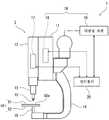
도 1은 실시형태에 따른 점 접합 장치의 마찰교반 점 접합 장치를 개략적으로 나타내는 구성도이다.
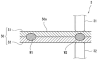
도 2는 저항 점 용접 공정을 설명하는 단면도이다.
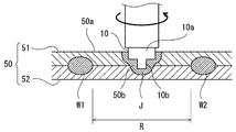
도 3은 마찰교반 점 접합 공정을 설명하는 단면도이다.
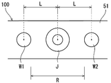
도 4는 이음 구조의 주요부 평면도이다.
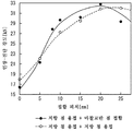
도 5는 인장-전단 시험에서의 접합 피치와 인장-전단강도와의 관계를 나타내는 그래프이다.
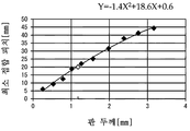
도 6은 저탄소강을 저항 점 용접할 때의 판 두께와 최소 접합 피치의 관계를 나타내는 그래프이다.
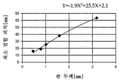
도 7은 중탄소강 또는 저합금강을 저항 점 용접할 때의 판 두께와 최소 접합 피치의 관계를 나타내는 그래프이다. BRIEF DESCRIPTION OF THE DRAWINGS Fig. 1 is a schematic view showing a friction stir spot joining apparatus of a point joining apparatus according to an embodiment. Fig.
2 is a cross-sectional view illustrating the resistance spot welding process.
3 is a cross-sectional view for explaining a friction stir welding process.
4 is a plan view of a main portion of the joint structure.
5 is a graph showing the relationship between the joint pitch and the tensile-shear strength in the tensile-shear test.
6 is a graph showing the relationship between the plate thickness and the minimum joint pitch when the low carbon steel is subjected to resistance spot welding.
7 is a graph showing the relationship between the plate thickness and the minimum joint pitch when resistance welding is performed on medium carbon steel or low alloy steel.
이하, 도면을 참조하여 실시형태를 설명한다. Hereinafter, embodiments will be described with reference to the drawings.
도 1은, 실시형태에 따른 점 접합 장치(1)의 마찰교반 점 접합 장치(2)를 개략적으로 나타내는 구성도이다. 도 1에 나타낸 바와 같이, 워크(50)는, 서로 중첩하여진 한 쌍의 판재(51, 52)이며, 마찰교반 점 접합 장치(2)는, 한 쌍의 판재(51, 52)의 중첩부(50a)를 점 접합한다. 마찰교반 점 접합 장치(2)는, 기체(基體)(11)와, 기체(11)에 장착된 가동체(12)와, 가동체(12)로부터 워크(50)를 향해 돌출된 툴 홀더(tool holder)(13)를 구비한다. 가동체(12)는, 툴 홀더(13)의 축선을 따라 슬라이드 변위 가능하게 기체(11)에 장착된다. 툴 홀더(13)는, 그 축선 주위로 회전 가능하게 구성되고, 툴 홀더(13)의 선단부에는, 툴(10)이 착탈 가능하게 장착된다. 기체(11)에는, 대략 L-자 모양으로 만곡된 만곡 프레임(14)이 고정된다. 만곡 프레임(14)은, 그 선단부가 툴(10)과 마주보는 위치까지 연장되고, 만곡 프레임(14)의 선단부에는, 워크(50)를 지지하는 지지대(15)가 설치된다. BRIEF DESCRIPTION OF DRAWINGS FIG. 1 is a schematic view showing a friction stir
기체(11)에는, 툴 홀더(13)의 축선 방향으로 가동체(12)를 슬라이드 변위 시키는 직동 구동기(16)가 설치된다. 직동 구동기(16)는, 가동체(12)를 슬라이드 변위 시킴으로써 툴(10)을 워크(50)에 대해 진퇴 변위 시킨다. 가동체(12)에는, 툴 홀더(13)를 그 축선 주위로 회전시키는 회전 구동기(17)가 설치된다. 회전 구동기(17)는, 툴 홀더(13)를 회전시킴으로써 툴(10)을 회전시킨다. 기체(11)에는, 다관절 로봇(18)이 장착된다. 다관절 로봇(18)은, 기체(11)를 변위 시킴으로써 워크(50)에 대해 툴(10)을 원하는 위치로 변위 시킨다. 즉, 직동 구동기(16) 및 다관절 로봇(18)이, 워크(50)와 툴(10)을 서로 상대 변위 시키는 변위 구동기(19)의 역할을 맡는다. The
마찰교반 점 접합 장치(2)는, 직동 구동기(16), 회전 구동기(17) 및 다관절 로봇(18)을 제어하는 컨트롤러(20)를 구비한다. 컨트롤러(20)는, 하나의 제어 유닛에 기능이 집약된 것으로 하여도 좋고, 복수의 제어 유닛에 기능이 분산된 구성으로 하여도 좋다. 컨트롤러(20)는, 프로세서, 휘발성 메모리, 비휘발성 메모리 및 I/O 인터페이스 등을 가진다. 컨트롤러(20)는, 도시하지 않은 입력 장치(예를 들면, 컴퓨터 또는 티칭 펜던트(teaching pendant) 등)로부터 I/O 인터페이스를 통해 입력된 지령에 응답하고, 비휘발성 메모리에 저장된 동작 프로그램에 의거하여 프로세서가 휘발성 메모리를 이용하여 연산하고, I/O 인터페이스를 통해 회전 구동기(17) 및 변위 구동기(19)와 통신한다. 마찰교반 점 접합 장치(2)는, 컨트롤러(20)로 하여금 회전 구동기(17) 및 변위 구동기(19)를 제어하게 함으로써, 한 쌍의 판재(51, 52)의 중첩부(50a)에 툴(10)을 회전시킨 상태로 압입하고, 중첩부(50a) 중 마찰열로 연화한 부분을 교반하여 소성 유동시켜, 마찰교반 점 접합을 수행한다. The friction stir
도 2는, 저항 점 용접 공정을 설명하는 단면도이다. 도 2에 나타낸 바와 같이, 본 실시형태의 점 접합 장치(1)는, 저항 점 용접 장치(3)를 더 구비한다. 저항 점 용접 장치(3)는, 한 쌍의 용접 전극(31, 32)과, 이들 용접 전극(31, 32)을 변위 시키는 액추에이터(도시하지 않음)와, 해당 액추에이터를 제어하는 컨트롤러(도시하지 않음)를 구비한다. 저항 점 용접 장치(3)는, 한 쌍의 판재(51, 52)의 중첩부(50a)를 한 쌍의 용접 전극(31, 32)으로 사이에 끼우고 통전하여 저항 용접함으로써, 중첩부(50a)에 소정의 간격을 두고 복수의 저항 점 용접부(W1, W2)(너깃(nugget))를 형성하여, 한 쌍의 판재(51, 52)를 서로 점 접합 한다. 2 is a cross-sectional view for explaining the resistance spot welding process. As shown in Fig. 2, the
도 3은, 마찰교반 점 접합 공정을 설명하는 단면도이다. 도 3에 나타낸 바와 같이, 마찰교반 점 접합 장치(2)는, 한 쌍의 판재(51, 52)의 중첩부(50a) 중 복수의 저항 점 용접부(W1, W2) 사이의 영역(R)에 적어도 하나의 마찰교반 점 접합부(J)를 형성하고, 한 쌍의 판재(51, 52)를 서로 점 접합한다. 툴(10)은, 툴 본체부(10a)와, 툴 본체부(10a)보다 작은 지름으로 툴 본체부(10a)의 중심으로부터 워크(50)를 향해서 돌출된 핀부(10b)를 가진다. 3 is a cross-sectional view for explaining a friction stir welding process. 3, the friction stir
마찰교반 점 접합에 있어서는, 컨트롤러(20)(도 1 참조)는, 회전 구동기(17)을 제어하여 툴(10)의 회전수가 목표 회전수가 된 상태에서, 직동 구동기(16)를 제어하여 핀부(10b)가 워크(50)의 중첩부(50a)를 내리누를 때까지 툴(10)을 변위 시킨다. 그러면, 툴(10)의 핀부(10b)가, 워크(50)의 중첩부(50a)를 마찰열에 의해 연화시키고, 그 연화 부분(50b)을 교반하여 소성유동시킨다. 컨트롤러(20)는, 소정의 접합 처리 시간(핀부(10b)의 몰입 시간)이 경과한 후, 직동 구동기(16)로 툴(10)을 워크(50)로부터 빼내는 방향으로 변위 시킨다. 툴(10)이 워크(50)로부터 빼내지면, 상기 연화 부분(50b)이 냉각되고 경화하여 마찰교반 점 접합부(J)가 형성된다. 또한, 마찰교반 점 접합은, 판재(51, 52)로의 통전을 수반하지 않기 때문에, 무효 전류의 문제는 발생할 수 없다. 이상과 같이, 한 쌍의 판재(51, 52)의 중첩부(50a)를 저항 점 용접과 마찰교반 점 접합 양쪽에 의해서 접합하는 것으로, 이음 구조(100)가 형성된다. 1) controls the
도 4는, 이음 구조(100)의 주요부 평면도이다. 도 3 및 도 4에 나타낸 바와 같이, 이음 구조(100)는, 한 쌍의 판재(51, 52)를 서로 중첩하여 점 접합하여 이루어지며, 자동차, 항공기, 철도차량 등의 구조체에 이용된다. 이음 구조(100)는, 한 쌍의 판재(51, 52)의 중첩부(50a)에 형성된 한 쌍의 저항 점 용접부(W1, W2)와, 한 쌍의 저항 점 용접부(W1, W2) 사이의 영역(R)에 형성된 하나의 마찰교반 점 접합부(J)를 가진다. 마찰교반 점 접합부(J)와 저항 점 용접부(W1, W2) 사이의 접합 피치(L), 즉, 마찰교반 점 접합부(J)의 중심과 저항 점 용접부(W1, W2) 각각의 중심 사이의 거리(L)는, 소정의 범위로 설정되는 것이 바람직하다. 이하, 접합 피치(L)의 알맞은 범위에 관하여 설명한다. 4 is a plan view of a main part of the
도 5는, 인장-전단 시험에서의 접합 피치와 인장-전단강도와의 관계를 나타내는 그래프이다. 이 인장-전단 시험에서는, 이음 구조를 구성하는 한 쌍의 판재로서, 저탄소강인 DP980 강판(인장 강도 980MPa)을 이용하고, 각 판재의 판 두께는 각각 1.2mm 하였다. 도 5 중의 검은색 플롯(plot)은, 한 개의 저항 점 용접부와 한 개의 마찰교반 점 접합부를 가지는 이음 구조를 인장-전단 시험한 결과(이하, 「저항 점 용접 + 마찰교반 점 접합」이라고 칭한다. )를 나타내며, 실선은 그 근사선이다. 도 5 중 흰색 플롯은, 2개의 저항 점 용접을 가지는 이음 구조를 인장-전단 시험한 결과(이하, 「저항 점 용접 + 저항 점 용접」이라고 칭한다. )를 나타내며, 점선은 그 근사선이다. 5 is a graph showing the relationship between the joint pitch and the tensile-shear strength in the tensile-shear test. In this tensile-shear test, a DP980 steel sheet (tensile strength: 980 MPa), which is a low-carbon steel, was used as a pair of plates constituting the joint structure, and each plate had a plate thickness of 1.2 mm. The black plot in FIG. 5 is a result of a tensile-shear test (hereinafter referred to as "resistance spot welding + friction stir welding") of a joint structure having one resistance point weld portion and one friction stir portion contact portion. ), And the solid line is its approximate line. The white plots in Fig. 5 represent the result of tensile-shear test (hereinafter referred to as " resistance spot welding + resistance spot welding ") of a joint structure having two resistance spot welding, and the dotted line is an approximate line thereof.
도 5에서 알 수 있듯이, 접합 피치가 6mm 이상 20mm 이하의 범위에서는, 「저항 점 용접 + 마찰교반 점 접합」 쪽이 「저항 점 용접 + 저항 점 용접」보다 인장-전단강도가 높다. 접합 피치가 너무 짧을 경우는, 저항 점 용접부와 마찰교반 점 접합부 사이의 접합 피치가, 저항 점 용접부의 반경과 마찰교반 점 접합부의 반경의 합계보다 짧아져, 저항 점 용접부와 마찰교반 점 접합부가 서로 중첩하여져서 합계 접합 면적이 감소하고, 이음 강도의 향상 효과가 감소한다. 그 때문에, 저항 점 용접부와 마찰교반 점 접합부가 서로 중첩되지 않도록, 접합 피치를 6mm 이상으로 하는 것이 바람직하다. 즉, 「저항 점 용접 + 마찰교반 점 접합」쪽이 「저항 점 용접 + 저항 점 용접」보다 인장-전단강도가 높아지는 접합 피치의 하한치는, 저항 점 용접부 및 마찰교반 점 접합부의 각 반경에 의존한다. 또한, 도 5에서 접합 피치가 0mm인 플롯은, 단일 점에서의 인장-전단강도를 나타내고 있고, 이 경우, 저항 점 용접부 쪽이 마찰교반 점 접합부보다 1점당 인장-전단강도가 높은 것을 의미하고 있다. 5, the "resistance spot welding + friction stir welding point" has higher tensile-shear strength than "resistance spot welding + resistance spot welding" in the range of the bonding pitch of 6 mm or more and 20 mm or less. When the joint pitch is too short, the joint pitch between the resistance spot welding portion and the friction stir welding point becomes shorter than the sum of the radius of the resistance spot welding portion and the radius of the friction stir welding point, The total joint area is reduced, and the effect of improving the joint strength is reduced. Therefore, it is preferable that the joint pitch is 6 mm or more so that the resistance spot welding portion and the friction stir welding point portions do not overlap with each other. That is, the lower limit of the joint pitch at which the "resistance spot welding + friction stir welding point" becomes higher than the "resistance point welding + resistance point welding" is higher than that of the resistance spot welding point and the friction stir welding point is dependent on each radius of the resistance spot welding portion and the friction stir welding point . In FIG. 5, the plot with a joint pitch of 0 mm shows the tensile-shear strength at a single point, and in this case, the resistance point weld portion has a higher tensile-shear strength per point than the friction stir point joint portion .
접합 피치가 긴 경우는, 저항 점 용접 시의 분류(分流)에 의해 발생하는 무효전류가 감소하기 때문에, 「저항 점 용접 + 저항 점 용접」 쪽이 「저항 점 용접 + 마찰교반 점 접합」보다 인장-전단강도가 높아진다. 그러나 접합 피치가 20mm 이하일 경우에는, 「저항 점 용접 + 저항 점 용접부」에서는 무효전류가 증가하기 때문에, 「저항 점 용접 + 마찰교반 점 접합」 쪽이 「저항 점 용접 + 저항 점 용접」보다 인장-전단강도가 높아진다. 예를 들면, 접합 피치가 10mm에서의 인장-전단 시험 후의 파단 형태의 비교에서, 「저항 점 용접 + 저항 점 용접」에서는, 2타점째의 저항 점 용접부가 1타점째의 저항 점 용접부보다 지름이 작아지게 되고, 계면 파단이 이루어지는 것이 확인되었지만, 「저항 점 용접 + 마찰교반 점 접합」에서는, 모재 파단이 이루어지는 것이 확인되었다. 그 때문에, 판 두께 1.2mm의 저탄소강 판재를 사용한 이음 구조에서는, 마찰교반 점 접합부와 저항 점 용접부 사이의 접합 피치는, 20mm 이하의 값으로 설정되는 것이 바람직하다. 「저항 점 용접 + 마찰교반 점 접합」 쪽이 「저항 점 용접 + 저항 점 용접」보다 인장-전단강도가 높아지는 접합 피치의 상한치는, 판재의 재질 및 두께에 따라 변하기 때문에, 이 점에 관해 아래에서 설명한다. When the joint pitch is long, since the reactive current generated by the splitting at the resistance spot welding is reduced, the "resistance spot welding + resistance spot welding" is more effective than the "resistance spot welding + friction stir welding" - Shearing strength increases. However, when the joint pitch is 20 mm or less, since the reactive current increases in the " resistance spot welding + resistance spot welding ", the " resistance spot welding + friction stir welding point & The shear strength is increased. For example, in the comparison of the fracture form after the tensile-shear test at the joint pitch of 10 mm, in the "resistance point welding + resistance point welding", the resistance point welding portion of the second- And it was confirmed that the interface fracture was caused. However, it was confirmed that the base material fracture occurred in "resistance spot welding + friction stir welding". Therefore, in the joint structure using the low carbon steel plate having the plate thickness of 1.2 mm, it is preferable that the joint pitch between the friction stir spot joint portion and the resistance spot weld portion is set to a value of 20 mm or less. The upper limit of the joint pitch at which the "resistance spot welding + friction stir welding point" is higher than the "resistance point welding + resistance point welding" is higher than that of the welding point-to-shear strength is more dependent on the material and thickness of the plate material. Explain.
도 6은, 저탄소강(S10C 등)을 저항 점 용접할 때의 판 두께와 최소 접합 피치의 관계를 나타내는 그래프이다. 도 7은, 중탄소강(S20C, S35C, S45C 등) 또는 저합금강(SNCM439, SCM435 등)을 저항 점 용접할 때의 판 두께와 최소 접합 피치의 관계를 나타내는 그래프이다. 저탄소강은, 탄소 함유율(질량 퍼센트 농도)이 0.20% 미만의 강이고, 중탄소강은, 탄소 함유율이 0.20% 이상 0.6% 이하의 강이며, 저합금강은, 철 및 탄소 이외의 합금 원소의 함유율(질량 퍼센트 농도)이 5% 이하의 강이다. 최소 접합 피치는, 한 쌍의 판재를 저항 점 용접만으로 접합할 경우에 요구되는 접합 피치의 하한치를 의미한다. 도 6 중의 실선은, 검은색 플롯의 근사선이며, 접합 피치를 Y(mm), 판 두께를 X(mm)로 했을 경우에, Y = -1.4 X2 + 18.6X + 0.6으로 표시된다. 도 7 중의 실선은, 검은색 플롯의 근사선이며, 접합 피치를 Y(mm), 판 두께를 X(mm)로 했을 경우에, Y = -1.9X2 + 25.5X + 2.1로 표시된다. Fig. 6 is a graph showing the relationship between the plate thickness and the minimum joint pitch when the low-carbon steel (S10C or the like) is subjected to resistance spot welding. 7 is a graph showing the relationship between the plate thickness and the minimum joint pitch at the time of resistance spot welding of medium carbon steels (S20C, S35C, S45C, etc.) or low alloy steels (SNCM439, SCM435, etc.). The low carbon steel is a steel having a carbon content (mass percent concentration) of less than 0.20%, the carbon steel having a carbon content of 0.20% or more and 0.6% or less, and the low alloy steel has a content Mass percent concentration) is less than 5%. The minimum joining pitch means the lower limit of the joining pitch required when joining a pair of plate members only by resistance spot welding. The solid line in FIG. 6 is an approximate line of a black plot, and is represented by Y = -1.4 X 2 + 18.6X + 0.6 when the joining pitch is Y (mm) and the plate thickness is X (mm). 7 in solid line, and the approximate line of the black plot, the bonding pitch Y (mm), the thickness when a by X (mm), is represented by Y = -1.9X 2 + 25.5X + 2.1 .
도 6 및 도 7에 나타낸 바와 같이, 한 쌍의 판재를 저항 점 용접만으로 접합한 경우에 요구되는 최소 접합 피치는, 판재의 판 두께가 증가할수록 길어진다. 또한, 한 쌍의 판재를 저항 점 용접만으로 접합한 경우에 요구되는 최소 접합 피치는, 판재를 저탄소강으로 했을 경우가 판재를 중탄소강 또는 저합금강으로 했을 경우보다 짧아진다. 즉, 판 두께가 증가하면 무효전류가 발생하기 쉽고, 또한, 저탄소강 쪽이 중탄소강 또는 저합금강보다 무효전류가 발생하기 어려워진다. As shown in Figs. 6 and 7, the minimum joint pitch required when joining a pair of plate members by resistance spot welding only becomes longer as the plate thickness of the plate member increases. In addition, when the pair of plate members are joined by resistance spot welding alone, the minimum joining pitch is shorter when the plate member is made of low carbon steel than when the plate member is made of medium carbon steel or low alloy steel. That is, when the plate thickness is increased, a reactive current is liable to occur, and moreover, the ineffective current is less likely to occur in the low carbon steel than in the medium carbon steel or the low alloy steel.
여기서, 도 5의 시험 결과(저탄소강; 판 두께 1.2mm)에서, 「저항 점 용접 + 마찰교반 점 접합」 쪽이 「저항 점 용접 + 저항 점 용접」보다 인장-전단강도가 높아진 접합 피치의 상한치(20mm)를, 도 6 중에 흰색 플롯으로 추가하여 기재하면, 그 흰색 플롯은, 대체로 그래프의 실선(Y = -1.4X2 + 18.6X + 0.6) 상에 위치한다. 따라서, 저항 점 용접부와 마찰교반 점 접합부가 이웃하는 이음 구조에서는, 판재가 저탄소강일 경우에, Y ≤ -1.4X2 + 18.6X + 0.6을 충족하도록 접합 피치의 상한치를 설정하고, 판재가 중탄소강일 경우에, Y ≤ -1.9X2 + 25.5X + 2.1을 충족하도록 접합 피치의 상한치를 설정하는 것이 바람직하다고 말할 수 있다. Here, in the test result (low carbon steel plate thickness: 1.2 mm) shown in FIG. 5, the "resistance spot welding + friction stir welding point" is the upper limit value of the welding pitch in which the tensile- (20 mm) is added with white plots in FIG. 6, the white plots are generally located on the solid line (Y = -1.4X 2 + 18.6X + 0.6) of the graph. Therefore, in the joint structure in which the resistance spot welding portion and the friction stir point bonding portion are adjacent to each other, the upper limit value of the joint pitch is set so as to satisfy Y? -1.4X 2 + 18.6X + 0.6 when the plate is low carbon steel, , It can be said that it is preferable to set the upper limit value of the joint pitch to satisfy Y? -1.9X 2 + 25.5X + 2.1.
이상에서, 컨트롤러(20)는, 판재(51, 52)가 저탄소강일 경우에는, 마찰교반 점 접합부(J)와 저항 점 용접부(W1, W2) 사이의 접합 피치(L)를, Y ≤ -1.4X2 + 18.6X + 0.6을 충족하도록 설정하고, 판재(51, 52)가 중탄소강 또는 저합금강일 경우에는, 마찰교반 점 접합부(J)와 저항 점 용접부(W1, W2) 사이의 접합 피치(L)를, Y ≤ -1.9X2 + 25.5X + 2.1을 충족하도록 설정한다. 또한, 컨트롤러(20)는, 마찰교반 점 접합부(J)와 저항 점 용접부(W1, W2) 사이의 접합 피치(L)를, 저항 점 용접부(J)의 반경과 마찰교반 점 접합부 W1(W2)의 반경의 합계보다 긴 값으로 설정한다. 즉, 컨트롤러(20)는, 마찰교반 점 접합부(J)와 저항 점 용접부(W1, W2) 사이의 접합 피치(L)를, 한 쌍의 판재에 마찰교반 점 접합부 및 저항 점 용접부 쌍을 형성한 경우의 인장-전단강도가 한 쌍의 판재에 저항 점 용접부 쌍을 형성한 경우의 인장-전단강도보다 높아지는 접합 피치로 설정한다. The
이상으로 설명한 구성에 의하면, 저항 점 용접부(W1, W2) 사이의 영역(R)에 마찰교반 점 접합부(J)를 형성함으로써, 저항 점 용접부(W1, W2) 간의 거리를 길게 하면서도, 전체적으로 점 접합 개소(저항 점 용접 개소 및 마찰교반 점 접합 개소)의 접합 피치(L)를 짧게 할 수 있다. 즉, 저항 점 용접부(W1, W2) 간의 거리를 길게 하여 무효전류를 억제함으로써, 접합강도 및 외관품질의 저하와 접합강도의 편차를 방지할 수 있고, 또한, 전체적으로 점 접합 개소의 접합 피치(L)를 짧게 함으로써, 이음 강도와 이음 구조(100)의 강성을 높일 수가 있다. The friction stir welding point J is formed in the region R between the resistance spot welding portions W1 and W2 so that the distance between the resistance spot welding portions W1 and W2 is long, It is possible to shorten the joint pitch L of the points (the resistance spot welding spot and the friction stir spot joint spot). That is, by reducing the reactive current by increasing the distance between the resistance spot welded portions W1 and W2, it is possible to prevent the deterioration of the joint strength and the appearance quality and the deviation of the joint strength, and the joint pitch L The joint strength and the rigidity of the
또한, 컨트롤러(20)는, 마찰교반 점 접합부(J)와 저항 점 용접부(W1, W2) 사이의 접합 피치(L)를, 「저항 점 용접부 + 마찰 교반 점 접합」 쪽이 「저항 점 용접부 + 저항 점 용접부」보다 인장-전단강도가 높아지는 접합 피치로 설정하므로, 저항 점 용접 시의 무효전류에 의한 접합강도 저하의 방지와 접합 피치의 단축화에 의한 접합강도의 향상을 알맞게 양립시킬 수 있다. 또한, 컨트롤러(20)는, 마찰교반 점 접합부(J)와 저항 점 용접부(W1, W2) 사이의 접합 피치(L)를, 저항 점 용접부(W1, W2)의 반경과 마찰교반 점 접합부(J)의 반경의 합계보다 긴 값으로 설정하므로, 마찰교반 점 접합부(J)와 저항 점 용접부(W1, W2)가 중첩하여져서 합계 접합 면적이 줄어드는 것이 방지되고, 효과적으로 접합강도를 높일 수가 있다. The
또한, 본 발명은 전술한 실시형태로 한정되는 것이 아니라, 그 구성을 변경, 추가, 또는 삭제할 수 있다. 예를 들면, 마찰교반 점 접합부(J)와 저항 점 용접부(W1) 사이의 접합 피치는, 마찰교반 점 접합부(J)와 저항 점 용접부(W2) 사이의 접합 피치와 달라도 좋다. 또한, 도 4에서는, 마찰교반 점 접합부(J)는, 한 쌍의 저항 점 용접부(W1, W2)를 잇는 직선상에 마련하였지만, 판재의 중첩부가 평면에서 바라볼 때 만곡된 만곡부를 가질 경우에는, 해당 만곡부의 연장 방향으로 연장되는 만곡선 상의 한 쌍의 저항 점 용접부 사이에 마련하여도 좋다. 또한, 변위 구동기는, 툴에 대해 워크를 이동시키는 것으로 하여도 좋다. 또한, 서로 중첩하여져서 점 접합되는 판재의 수는 3장 이상이어도 좋다. Further, the present invention is not limited to the above-described embodiments, but the configuration thereof can be changed, added, or deleted. For example, the joint pitch between the friction stir spot joining portion J and the resistance spot welding portion W1 may be different from the joint pitch between the friction stir spot joining portion J and the resistance spot welding portion W2. In Fig. 4, the friction stir spot joint J is provided on a straight line connecting the pair of resistance spot welds W1 and W2. However, when the overlapping portion of the plate material has a curved bent portion when viewed from the plane And a pair of resistance spot welding portions on the curved line extending in the extending direction of the corresponding curved portion. Further, the displacement driver may move the work relative to the tool. In addition, the number of the plate members overlapping each other by point bonding may be three or more.
1 : 점 접합 장치
2 : 마찰교반 점 접합 장치
3 : 저항 점 용접 장치
10 : 툴
17 : 회전 구동기
19 : 변위 구동기
20 : 컨트롤러
50a : 중첩부
51, 52 : 판재
100 : 이음 구조
J : 마찰교반 점 접합부
L : 접합 피치
W1, W2 : 저항 점 용접부1: Point bonding apparatus 2: Friction stir point bonding apparatus
3: Resistance point welding apparatus 10: Tool
17: Rotary actuator 19: Displacement actuator
20:
51, 52: plate member 100: joint structure
J: friction stir point joint L: joint pitch
W1, W2: resistance spot welding portion
Claims (9)
상기 복수의 판재의 중첩부와 툴을 서로 상대 변위 시키는 변위 구동기와,
상기 툴을 회전시키는 회전 구동기와,
상기 중첩부에 상기 툴을 회전시킨 상태로 압입하여 마찰교반 점 접합을 하도록 상기 변위 구동기 및 상기 회전 구동기를 제어하는 컨트롤러를 구비하며,
상기 컨트롤러는, 상기 중첩부 중 저항 점 용접으로 용접되는 복수의 저항 점 용접부 사이의 영역에 하나 이상의 마찰교반 점 접합부를 형성하도록 상기 변위 구동기를 제어하는 것을 특징으로 하는 점 접합 장치.
1. A point bonding apparatus for superposing a plurality of plate materials to perform point bonding,
A displacement driver for relatively displacing the overlapping portion of the plurality of plate materials and the tool,
A rotation driver for rotating the tool,
And a controller for controlling the displacement driver and the rotation driver to press-fit the tool into the overlapping portion while rotating the tool so as to perform friction stir welding,
Wherein the controller controls the displacement driver to form one or more friction stir point junctions in a region between a plurality of resistance spot welding portions welded by resistance spot welding among the overlapped portions.
상기 컨트롤러는, 상기 마찰교반 점 접합부와 상기 저항 점 용접부 사이의 접합 피치를, 상기 복수의 판재에 마찰교반 점 접합부 및 저항 점 용접부 쌍을 형성한 경우의 인장-전단강도가, 상기 복수의 판재에 저항 점 용접부 쌍을 형성한 경우의 인장-전단강도보다 높아지는 접합 피치로 설정하는 것을 특징으로 하는 점 접합 장치.
The method according to claim 1,
The controller is characterized in that a joint pitch between the friction stir spot joining portion and the resistance spot welding portion is set such that a tensile-shear strength in a case where a pair of the friction stir spot joining portion and the resistance spot welding portion is formed on the plurality of plate materials, And the joint pitch is set to be higher than the tensile-shear strength in the case of forming a pair of resistance spot welding portions.
상기 판재는 강재이고,
상기 마찰교반 점 접합부와 상기 저항 점 용접부 사이의 접합 피치를 'Y'라고 하고, 상기 한 쌍의 판재 각각의 판 두께를 'X'라고 했을 때,
상기 컨트롤러는, 상기 판재가 저탄소강인 경우, Y ≤ -1.4 X2 + 18.6X + 0.6을 충족하도록 상기 접합 피치를 설정하고, 상기 판재가 중탄소강 또는 저합금강인 경우, Y ≤ -1.9X2 + 25.5X + 2.1을 충족하도록 상기 접합 피치를 설정하는 것을 특징으로 하는 점 접합 장치.
3. The method according to claim 1 or 2,
The plate material is a steel material,
And a joint pitch between the friction stir welding point and the resistance spot welding portion is denoted by Y and a thickness of each of the pair of plate members is denoted by X,
Wherein the controller, if the plate material is a low-carbon robust, Y ≤ -1.4 X 2 + 18.6X + to meet the 0.6 setting the bonding pitch, and wherein the sheet material is carbon steel or low-alloy steel of, Y ≤ 2 -1.9X + 25.5X + 2.1. ≪ / RTI >
상기 컨트롤러는, 상기 마찰교반 점 접합부와 상기 저항 점 용접부 사이의 접합 피치를, 상기 저항 점 용접부의 반경과 상기 마찰교반 점 접합부의 반경의 합계보다 긴 값으로 설정하는 것을 특징으로 하는 점 접합 장치.
4. The method according to any one of claims 1 to 3,
Wherein the controller sets the joint pitch between the friction stir welding point and the resistance spot welding to a value longer than the sum of the radius of the resistance spot welding and the radius of the friction stir welding point.
상기 복수의 판재의 중첩부를 저항 점 용접으로 점 접합함으로써 복수의 저항 점 용접부를 형성하는 저항 점 용접 공정과,
상기 중첩부 중 상기 복수의 저항 점 용접부 사이의 영역을 마찰교반 점 접합으로 점 접합함으로써 하나 이상의 마찰교반 점 접합부를 형성하는 마찰교반 점 접합 공정을 구비하는 것을 특징으로 하는 점 접합 방법.
A point joining method for joining a plurality of plate materials to each other by superposition,
A resistance spot welding step of forming a plurality of resistance spot welding portions by point bonding the overlapped portions of the plurality of plate materials by resistance spot welding;
And a friction stir spot joining step of forming at least one friction stir spot joining portion by point bonding the regions between the plurality of resistance spot welding portions of the overlapping portions by friction stir spot joining.
상기 마찰교반 점 접합부와 상기 저항 점 용접부 사이의 접합 피치를, 상기 복수의 판재에 마찰교반 점 접합부 및 저항 점 용접부 쌍을 형성한 경우의 인장-전단강도가, 상기 복수의 판재에 저항 점 용접부 쌍을 형성한 경우의 인장-전단강도보다 높아지는 접합 피치로 설정하는 것을 특징으로 하는 점 접합 방법.
6. The method of claim 5,
Wherein a joint pitch between the friction stir spot joint portion and the resistance spot weld portion is set such that the tensile-shear strength in the case where the friction stir spot joint portions and the resistance spot weld portion pairs are formed on the plurality of plate materials, And the tensile-shear strength in the case of forming the tensile-shear strength is set to be higher than the tensile-shear strength.
상기 판재는 강재이고,
상기 마찰교반 점 접합부와 상기 저항 점 용접부 사이의 접합 피치를 'Y'라고 하고, 상기 한 쌍의 판재 각각의 판 두께를 'X'라고 했을 때,
상기 판재가 저탄소강인 경우, Y ≤ -1.4 X2 + 18.6X + 0.6을 충족하도록 상기 접합 피치를 설정하고, 상기 판재가 중탄소강 또는 저합금강인 경우, Y ≤ -1.9X2 + 25.5X + 2.1을 충족하도록 상기 접합 피치를 설정하는 것을 특징으로 하는 점 접합 방법.
The method according to claim 5 or 6,
The plate material is a steel material,
And a joint pitch between the friction stir welding point and the resistance spot welding portion is denoted by Y and a thickness of each of the pair of plate members is denoted by X,
If the plate material is a low-carbon robust, Y ≤ -1.4 X 2 + 18.6X + to meet the 0.6 setting the bonding pitch, and when the sheet is of carbon steel or low alloy steel, Y ≤ 25.5X + 2 -1.9X + 2.1 And the bonding pitch is set so as to satisfy the following conditional expression.
상기 마찰교반 점 접합부와 상기 저항 점 용접부 사이의 접합 피치를, 상기 저항 점 용접부의 반경과 상기 마찰교반 점 접합부의 반경의 합계보다 긴 값으로 설정하는 것을 특징으로 하는 점 접합 방법.
8. The method according to any one of claims 5 to 7,
Wherein the joint pitch between the friction stir welding point and the resistance spot welding is set to be longer than the sum of the radius of the resistance spot welding and the radius of the friction stir welding point.
상기 복수의 판재의 중첩부에 형성된 복수의 저항 점 용접부와,
상기 중첩부 중 상기 복수의 저항 점 용접부 사이의 영역에 형성된 하나 이상의 마찰교반 점 접합부를 구비하는 것을 특징으로 하는 이음 구조.A joint structure in which a plurality of plate members are superimposed on each other and are point-
A plurality of resistance spot welding portions formed on the overlapping portions of the plurality of plate materials,
And at least one friction stir spot joint portion formed in a region between the plurality of resistance spot weld portions of the overlap portion.
Applications Claiming Priority (3)
| Application Number | Priority Date | Filing Date | Title |
|---|---|---|---|
| JPJP-P-2016-090611 | 2016-04-28 | ||
| JP2016090611A JP6393707B2 (en) | 2016-04-28 | 2016-04-28 | Spot joining apparatus, spot joining method and joint structure |
| PCT/JP2017/016816 WO2017188399A1 (en) | 2016-04-28 | 2017-04-27 | Spot welding device, spot welding method, and joint structure |
Publications (2)
| Publication Number | Publication Date |
|---|---|
| KR20180132154A true KR20180132154A (en) | 2018-12-11 |
| KR102207831B1 KR102207831B1 (en) | 2021-01-26 |
Family
ID=60160780
Family Applications (1)
| Application Number | Title | Priority Date | Filing Date |
|---|---|---|---|
| KR1020187033701A Expired - Fee Related KR102207831B1 (en) | 2016-04-28 | 2017-04-27 | Point bonding device, point bonding method and joint structure |
Country Status (6)
| Country | Link |
|---|---|
| US (1) | US11040413B2 (en) |
| EP (1) | EP3450080B1 (en) |
| JP (1) | JP6393707B2 (en) |
| KR (1) | KR102207831B1 (en) |
| CN (1) | CN109070264B (en) |
| WO (1) | WO2017188399A1 (en) |
Cited By (2)
| Publication number | Priority date | Publication date | Assignee | Title |
|---|---|---|---|---|
| KR102230872B1 (en) * | 2019-12-19 | 2021-03-24 | 주식회사 포스코 | Manufacturing method of titanium ring for electro-deposition drum and titanium ring manufactured thereof |
| KR20220024921A (en) * | 2019-07-01 | 2022-03-03 | 카와사키 주코교 카부시키 카이샤 | Bonding system and its operation method |
Families Citing this family (10)
| Publication number | Priority date | Publication date | Assignee | Title |
|---|---|---|---|---|
| KR102315903B1 (en) * | 2017-09-04 | 2021-10-21 | 카와사키 주코교 카부시키 카이샤 | Operation method of double acting friction stir welding device and double acting friction stir welding device |
| KR102477654B1 (en) | 2018-10-11 | 2022-12-14 | 카와사키 주코교 카부시키 카이샤 | Friction stir welding device, its operation method and joint structure |
| US10442029B1 (en) * | 2019-04-10 | 2019-10-15 | King Saud University | Method of friction stir spot welding |
| CN111468849B (en) * | 2020-04-15 | 2021-07-13 | 广东省资源综合利用研究所 | Rare earth magnetic disk welding process |
| US11958126B2 (en) * | 2020-10-06 | 2024-04-16 | GE Precision Healthcare LLC | Containers for retaining anesthetic agent and manufacturing methods thereof |
| US20240316873A1 (en) * | 2020-12-28 | 2024-09-26 | Kawasaki Jukogyo Kabushiki Kaisha | Joining method, joined body, and joining device |
| JP7524122B2 (en) * | 2021-03-30 | 2024-07-29 | 川崎重工業株式会社 | Joined structure and joining method |
| US12454024B2 (en) * | 2021-05-14 | 2025-10-28 | Kawasaki Jukogyo Kabushiki Kaisha | Joining method and joined body |
| JP7353329B2 (en) * | 2021-07-16 | 2023-09-29 | 本田技研工業株式会社 | Welding device and method for friction stir welding and resistance welding |
| EP4360796A4 (en) * | 2021-08-31 | 2024-10-16 | JFE Steel Corporation | FRICTION STIR SPOT WELDED JOINT, ITS PRODUCTION METHOD AND FRICTION STIR SPOT WELDING METHOD |
Citations (5)
| Publication number | Priority date | Publication date | Assignee | Title |
|---|---|---|---|---|
| JPS565405B2 (en) | 1976-01-09 | 1981-02-04 | ||
| JP2004276724A (en) * | 2003-03-14 | 2004-10-07 | Tokyu Car Corp | Car body for rolling stock and its manufacturing method |
| JP2008030100A (en) * | 2006-07-31 | 2008-02-14 | Toyota Motor Corp | Dissimilar metal joint structure and dissimilar metal joining method |
| JP2009202828A (en) * | 2008-02-29 | 2009-09-10 | Mazda Motor Corp | Manufacturing method and manufacturing line of vehicle body |
| JP2015033706A (en) * | 2013-08-08 | 2015-02-19 | 株式会社神戸製鋼所 | Spot laser composite weld joint |
Family Cites Families (13)
| Publication number | Priority date | Publication date | Assignee | Title |
|---|---|---|---|---|
| JP2580029B2 (en) * | 1989-03-20 | 1997-02-12 | ファナック株式会社 | Variable-pitch spot welding gun device for welding robot |
| EP1346792A1 (en) * | 2002-03-21 | 2003-09-24 | H.A. Schlatter Ag | Welding unit |
| JP3860153B2 (en) * | 2003-09-12 | 2006-12-20 | 川崎重工業株式会社 | Joint structure |
| JP2006167747A (en) * | 2004-12-15 | 2006-06-29 | Honda Motor Co Ltd | Welding apparatus and processing method |
| DE102005001341B3 (en) * | 2005-01-11 | 2006-10-05 | Kuka Schweissanlagen Gmbh | Method and device for electric spot welding |
| US20080149687A1 (en) * | 2006-12-22 | 2008-06-26 | Garnett Mark D | Weld Inspection Optimizer |
| JP5521421B2 (en) * | 2009-07-21 | 2014-06-11 | スズキ株式会社 | Double welding gun structure |
| JP5391046B2 (en) * | 2009-12-07 | 2014-01-15 | 川崎重工業株式会社 | Friction stir welding apparatus and joining method thereof |
| US8052029B1 (en) * | 2010-09-01 | 2011-11-08 | GM Global Technology Operations LLC | Method of calibrating a friction stir spot welding system |
| JP5605405B2 (en) | 2012-08-07 | 2014-10-15 | 新日鐵住金株式会社 | Resistance welded joint |
| KR101382319B1 (en) * | 2012-12-17 | 2014-04-08 | 현대자동차 주식회사 | Twin spot welding apparatus |
| CN103170752A (en) * | 2013-04-09 | 2013-06-26 | 上海电机学院 | Friction stir spot welding (FSSW) device of resistor and method thereof |
| DE102016206759A1 (en) * | 2015-07-21 | 2017-01-26 | Ford Global Technologies, Llc | A method for joining at least two metal workpieces lying on each other |
-
2016
- 2016-04-28 JP JP2016090611A patent/JP6393707B2/en active Active
-
2017
- 2017-04-27 CN CN201780025929.1A patent/CN109070264B/en not_active Expired - Fee Related
- 2017-04-27 EP EP17789680.0A patent/EP3450080B1/en active Active
- 2017-04-27 KR KR1020187033701A patent/KR102207831B1/en not_active Expired - Fee Related
- 2017-04-27 WO PCT/JP2017/016816 patent/WO2017188399A1/en not_active Ceased
- 2017-04-27 US US16/097,496 patent/US11040413B2/en not_active Expired - Fee Related
Patent Citations (5)
| Publication number | Priority date | Publication date | Assignee | Title |
|---|---|---|---|---|
| JPS565405B2 (en) | 1976-01-09 | 1981-02-04 | ||
| JP2004276724A (en) * | 2003-03-14 | 2004-10-07 | Tokyu Car Corp | Car body for rolling stock and its manufacturing method |
| JP2008030100A (en) * | 2006-07-31 | 2008-02-14 | Toyota Motor Corp | Dissimilar metal joint structure and dissimilar metal joining method |
| JP2009202828A (en) * | 2008-02-29 | 2009-09-10 | Mazda Motor Corp | Manufacturing method and manufacturing line of vehicle body |
| JP2015033706A (en) * | 2013-08-08 | 2015-02-19 | 株式会社神戸製鋼所 | Spot laser composite weld joint |
Cited By (3)
| Publication number | Priority date | Publication date | Assignee | Title |
|---|---|---|---|---|
| KR20220024921A (en) * | 2019-07-01 | 2022-03-03 | 카와사키 주코교 카부시키 카이샤 | Bonding system and its operation method |
| US12064831B2 (en) | 2019-07-01 | 2024-08-20 | Kawasaki Jukogyo Kabushiki Kaisha | Joining system, and method for operating same |
| KR102230872B1 (en) * | 2019-12-19 | 2021-03-24 | 주식회사 포스코 | Manufacturing method of titanium ring for electro-deposition drum and titanium ring manufactured thereof |
Also Published As
| Publication number | Publication date |
|---|---|
| US20190143442A1 (en) | 2019-05-16 |
| CN109070264B (en) | 2021-08-20 |
| JP6393707B2 (en) | 2018-09-19 |
| EP3450080A4 (en) | 2019-12-04 |
| KR102207831B1 (en) | 2021-01-26 |
| WO2017188399A1 (en) | 2017-11-02 |
| EP3450080A1 (en) | 2019-03-06 |
| EP3450080B1 (en) | 2023-10-04 |
| CN109070264A (en) | 2018-12-21 |
| JP2017196649A (en) | 2017-11-02 |
| US11040413B2 (en) | 2021-06-22 |
Similar Documents
| Publication | Publication Date | Title |
|---|---|---|
| KR20180132154A (en) | Point bonding device, point bonding method and bonding structure | |
| JP7029610B2 (en) | Welding method | |
| JP5261984B2 (en) | Resistance spot welding method | |
| JP7010720B2 (en) | Resistance spot welding method | |
| WO2012121086A1 (en) | Method for bonding dissimilar metals to each other | |
| KR102127991B1 (en) | Resistance spot welding method and welded structure | |
| JP2012187617A (en) | Joined body of high tensile strength steel sheet and resistance welding method for high tensile strength steel sheet | |
| JP2009226446A (en) | Spot welding method of dissimilar plates | |
| CN113993656B (en) | Engagement system and method of operation thereof | |
| JP7842529B2 (en) | Spot welding method | |
| JP5609966B2 (en) | Resistance spot welding method | |
| JP2012187616A (en) | Resistance welding apparatus and resistance welding method | |
| JP6104013B2 (en) | Spot welding method and spot welding apparatus | |
| JP5872319B2 (en) | One-side spot welding apparatus and one-side spot welding method | |
| JP2024008814A (en) | Spot welding method and welded joints for aluminum or aluminum alloy materials | |
| KR102773336B1 (en) | Spot welding method and welding joint for aluminum or aluminum alloy material | |
| KR20160054594A (en) | Resistance spot welding method and welded structure | |
| JP2016030291A (en) | Method for joining plate-like members | |
| CN117359071A (en) | Method for spot welding aluminum or aluminum alloy material and welded joint | |
| JP2019523711A (en) | Using resistance spot welding electrodes and electrodes | |
| JP2006315029A (en) | Laser welding method | |
| JP2012187615A (en) | Joined body of high tensile strength steel sheet and resistance welding method for high tensile strength steel sheet | |
| JP2016032830A (en) | Joining method of plate-shaped member | |
| JP2019150834A (en) | Resistance-welding electrode | |
| JP2008142731A (en) | Laser welding method, laser welding apparatus, and laser lap weld joint |
Legal Events
| Date | Code | Title | Description |
|---|---|---|---|
| A201 | Request for examination | ||
| AMND | Amendment | ||
| P11-X000 | Amendment of application requested |
St.27 status event code: A-2-2-P10-P11-nap-X000 |
|
| P13-X000 | Application amended |
St.27 status event code: A-2-2-P10-P13-nap-X000 |
|
| PA0105 | International application |
St.27 status event code: A-0-1-A10-A15-nap-PA0105 |
|
| PA0201 | Request for examination |
St.27 status event code: A-1-2-D10-D11-exm-PA0201 |
|
| PG1501 | Laying open of application |
St.27 status event code: A-1-1-Q10-Q12-nap-PG1501 |
|
| E902 | Notification of reason for refusal | ||
| PE0902 | Notice of grounds for rejection |
St.27 status event code: A-1-2-D10-D21-exm-PE0902 |
|
| AMND | Amendment | ||
| P11-X000 | Amendment of application requested |
St.27 status event code: A-2-2-P10-P11-nap-X000 |
|
| P13-X000 | Application amended |
St.27 status event code: A-2-2-P10-P13-nap-X000 |
|
| E902 | Notification of reason for refusal | ||
| PE0902 | Notice of grounds for rejection |
St.27 status event code: A-1-2-D10-D21-exm-PE0902 |
|
| AMND | Amendment | ||
| P11-X000 | Amendment of application requested |
St.27 status event code: A-2-2-P10-P11-nap-X000 |
|
| P13-X000 | Application amended |
St.27 status event code: A-2-2-P10-P13-nap-X000 |
|
| E601 | Decision to refuse application | ||
| PE0601 | Decision on rejection of patent |
St.27 status event code: N-2-6-B10-B15-exm-PE0601 |
|
| X091 | Application refused [patent] | ||
| AMND | Amendment | ||
| E13-X000 | Pre-grant limitation requested |
St.27 status event code: A-2-3-E10-E13-lim-X000 |
|
| P11-X000 | Amendment of application requested |
St.27 status event code: A-2-2-P10-P11-nap-X000 |
|
| P13-X000 | Application amended |
St.27 status event code: A-2-2-P10-P13-nap-X000 |
|
| PX0901 | Re-examination |
St.27 status event code: A-2-3-E10-E12-rex-PX0901 |
|
| PX0701 | Decision of registration after re-examination |
St.27 status event code: A-3-4-F10-F13-rex-PX0701 |
|
| X701 | Decision to grant (after re-examination) | ||
| GRNT | Written decision to grant | ||
| PR0701 | Registration of establishment |
St.27 status event code: A-2-4-F10-F11-exm-PR0701 |
|
| PR1002 | Payment of registration fee |
St.27 status event code: A-2-2-U10-U12-oth-PR1002 Fee payment year number: 1 |
|
| PG1601 | Publication of registration |
St.27 status event code: A-4-4-Q10-Q13-nap-PG1601 |
|
| PR1001 | Payment of annual fee |
St.27 status event code: A-4-4-U10-U11-oth-PR1001 Fee payment year number: 4 |
|
| PC1903 | Unpaid annual fee |
St.27 status event code: A-4-4-U10-U13-oth-PC1903 Not in force date: 20250121 Payment event data comment text: Termination Category : DEFAULT_OF_REGISTRATION_FEE |
|
| H13 | Ip right lapsed |
Free format text: ST27 STATUS EVENT CODE: N-4-6-H10-H13-OTH-PC1903 (AS PROVIDED BY THE NATIONAL OFFICE); TERMINATION CATEGORY : DEFAULT_OF_REGISTRATION_FEE Effective date: 20250121 |
|
| PC1903 | Unpaid annual fee |
St.27 status event code: N-4-6-H10-H13-oth-PC1903 Ip right cessation event data comment text: Termination Category : DEFAULT_OF_REGISTRATION_FEE Not in force date: 20250121 |