JP2016032830A - Joining method of plate-shaped member - Google Patents
Joining method of plate-shaped member Download PDFInfo
- Publication number
- JP2016032830A JP2016032830A JP2014156570A JP2014156570A JP2016032830A JP 2016032830 A JP2016032830 A JP 2016032830A JP 2014156570 A JP2014156570 A JP 2014156570A JP 2014156570 A JP2014156570 A JP 2014156570A JP 2016032830 A JP2016032830 A JP 2016032830A
- Authority
- JP
- Japan
- Prior art keywords
- joining
- plate
- welding
- planned
- welding electrode
- Prior art date
- Legal status (The legal status is an assumption and is not a legal conclusion. Google has not performed a legal analysis and makes no representation as to the accuracy of the status listed.)
- Pending
Links
Images


Landscapes
- Body Structure For Vehicles (AREA)
- Butt Welding And Welding Of Specific Article (AREA)
Abstract
Description
本発明は、板状部材の接合方法に関する。 The present invention relates to a method for joining plate-like members.
例えば自動車の車体を構成する板状部材には、通常、鋼板が使用されている。また、重ね合わせた複数枚の鋼板を接合するための手段として、他の接合手段に比べて低コストで、安定した接合品質を得ることのできる抵抗スポット溶接が多く用いられる傾向にある。 For example, a steel plate is usually used for a plate-like member constituting an automobile body. In addition, as a means for joining a plurality of superposed steel plates, resistance spot welding that can obtain stable joining quality at a lower cost than other joining means tends to be used.
ところで、近年の自動車に対する低燃費化の要求に伴って、車体に対する軽量化の要求が高まっている。また、乗員の安全性や操作安定性(あるいは乗り心地)向上のため、車体の剛性、特にキャビン部の高剛性化に対する要求も高まっている。キャビン部のドア開口部における接合強度は、キャビン部の剛性に大きく寄与することから、ドア開口部の接合強度を向上させることが必要になる。 By the way, with recent demands for fuel efficiency reduction for automobiles, demands for weight reduction of vehicle bodies are increasing. In addition, in order to improve the safety and operating stability (or riding comfort) of the occupant, there is an increasing demand for increasing the rigidity of the vehicle body, particularly the cabin portion. Since the bonding strength at the door opening of the cabin greatly contributes to the rigidity of the cabin, it is necessary to improve the bonding strength of the door opening.
このように、軽量化と高剛性化を両立するために、車体用鋼板にハイテンなどの高張力鋼板を採用して従来よりも板厚を小さくすると共に、1部材あたりの溶接数を増加することが検討され始めている。しかしながら、高張力鋼板は、従来の鋼板に比べて溶接性に乏しく、このことに起因して接合強度が弱いといった問題がある。また、抵抗スポット溶接だと、板厚比が大きい場合に良好な接合部(例えばナゲットなど)を形成することが困難であったり、抵抗スポット溶接のピッチを小さくしていくと、隣り合う溶接ポイントで既に形成された接合部に分流が生じるため、溶接数を思うように増やせない、といった問題がある。 In this way, in order to achieve both weight reduction and high rigidity, a high-tensile steel plate such as high tension is adopted for the steel plate for the vehicle body to reduce the plate thickness and increase the number of welds per member. Has begun to be considered. However, the high-tensile steel plate has poor weldability as compared with the conventional steel plate, resulting in a problem that the bonding strength is weak. Also, with resistance spot welding, it is difficult to form a good joint (such as nuggets) when the plate thickness ratio is large, or when the resistance spot welding pitch is reduced, adjacent welding points However, there is a problem that the number of welds cannot be increased as expected because a diversion occurs in the joint portion already formed.
上述の問題に対処するため、例えばアーク溶接を利用したアークスポット溶接の導入が検討されている(例えば特許文献1を参照)。 In order to cope with the above-mentioned problem, for example, introduction of arc spot welding using arc welding has been studied (see, for example, Patent Document 1).
しかしながら、アークスポット溶接は、母材の接合予定領域上に溶接用トーチを移動させた後、母材との間にアークを発生させることにより行われるものであるから、複数箇所にアークスポット溶接を施す場合、その都度アークを発生させる必要が生じる。アーク放電初期におけるアーク発生不良が多いことに鑑みれば、極力アーク放電のスタート回数は少なくしたいが、上述のように接合箇所の数だけアークを発生させていたのでは、その分アークの発生不良率が高まる、との問題があった。特に、相応の大きさの溶け込みを得ようとすれば、その分電流値を高める必要があるため、よりアークスタート時の安定性に欠けやすい、との問題があった。 However, arc spot welding is performed by moving the welding torch over the base material joining area and then generating an arc with the base material. When applied, it is necessary to generate an arc each time. Considering that there are many arc failures at the beginning of arc discharge, we want to reduce the number of arc discharge starts as much as possible. However, if arcs were generated as many as the number of joints as described above, the rate of arc generation failure There was a problem that increased. In particular, in order to obtain a penetration of a corresponding size, there is a problem that since the current value needs to be increased by that amount, the stability at the start of the arc is more likely to be lacking.
以上の事情に鑑み、本発明により解決すべき課題は、抵抗スポット溶接では困難な条件下においても、安定した接合品質を得ることのできる接合方法を提供することにある。 In view of the above circumstances, the problem to be solved by the present invention is to provide a joining method capable of obtaining stable joining quality even under conditions difficult to achieve by resistance spot welding.
前記課題の解決は、本発明に係る板状部材の接合方法によって達成される。すなわち、この接合方法は、重ね合わせた複数の板状部材の平面方向に沿って溶接電極を移動させながら複数の接合予定領域に順次アーク溶接を施すことで、複数の板状部材を接合するための方法であって、各々の接合予定領域上で溶接電極を蛇行させると共に、接合予定領域上への侵入位置と接合予定領域上からの退出位置とが異なるように溶接電極を移動させる点をもって特徴付けられる。 The solution to the above problem is achieved by the method for joining plate members according to the present invention. That is, this joining method joins a plurality of plate-shaped members by sequentially performing arc welding on a plurality of planned joining regions while moving the welding electrodes along the planar direction of the plurality of stacked plate-shaped members. The welding electrode is meandered on each planned joining area, and the welding electrode is moved so that the entry position on the joining planned area and the exit position from the planned joining area are different. Attached.
このように溶接電極を溶接予定領域上で蛇行させながらアーク溶接を行うことで、溶接予定領域に対する過度な加熱を防ぎつつ平面方向に大きなサイズの溶け込みを得ることができる。よって、溶接予定領域に良好な接合部を形成することが可能となる。もちろん、適当な大きさの電流値で足りるため、スラグの発生も抑制できる。また、接合予定領域上への侵入位置と退出位置とが異なるように溶接電極を移動させるようにしたので、一の接合予定領域上からこれと隣り合う他の接合予定領域上へと、その軌跡が途切れることなく連続的に(いわば一筆書きの態様で)溶接電極を移動させることができる。このような移動態様であれば、母材(板状部材)との間で発生させたアークを維持しながら順次隣り合う接合予定領域上に移動することができるので、その都度アーク放電を開始することなく各接合予定領域において板状部材との間でアークを安定的に発生させることができる。よって、何れの接合予定領域においても安定した接合品質を得ることができる。また、その都度溶接電極を停止して、アークが安定するまで電流を流し続ける必要がないため、短時間でかつエネルギーコストを抑えてアーク溶接を実施することが可能となる。 Thus, by performing arc welding while meandering the welding electrode on the planned welding region, it is possible to obtain a large size penetration in the plane direction while preventing excessive heating of the planned welding region. Therefore, it is possible to form a good joint in the planned welding area. Of course, the generation of slag can be suppressed because an appropriate current value is sufficient. In addition, since the welding electrode is moved so that the entry position and the exit position on the planned joining area are different, the trajectory from one planned joining area to another joining planned area adjacent thereto. The welding electrode can be moved continuously (in a so-called one-stroke mode) without interruption. With such a movement mode, the arc generated between the base material (plate-like member) can be sequentially moved onto adjacent joining scheduled areas, and thus arc discharge is started each time. It is possible to stably generate an arc between the plate-like members in each of the planned joining regions. Therefore, stable bonding quality can be obtained in any bonding scheduled region. In addition, since it is not necessary to stop the welding electrode each time and keep the current flowing until the arc is stabilized, arc welding can be performed in a short time and with reduced energy costs.
また、本発明に係る接合方法は、溶接電極が互いに隣り合う接合予定領域の間を移動する間の電流値を、板状部材への溶け込みが生じない程度の大きさに設定するものであってもよい。 In the joining method according to the present invention, the current value while the welding electrodes move between adjacent joining regions is set to a magnitude that does not cause melting into the plate member. Also good.
このように電流値を調整することで、接合予定領域以外の領域を移動する際は、母材となる板状部材との間に発生させたアークを維持しつつも、過度な加熱による母材への溶け込みを防止して、エネルギーコストを節約することができる。よって、安定した品質の接合部を予定した複数の領域に無駄なく形成することが可能となる。 By adjusting the current value in this way, when moving the region other than the planned joining region, the base material due to excessive heating is maintained while maintaining the arc generated between the base material and the plate-like member. It is possible to save energy costs by preventing penetration into the water. Therefore, it is possible to form a stable quality joint in a plurality of planned areas without waste.
また、本発明に係る接合方法は、溶接電極が接合予定領域上を蛇行する際の軌跡が交差のない形状に設定されるものであってもよいし、より好ましくは、溶接電極が接合予定領域上を蛇行する間に形成される溶融部が、板状部材を平面視した状態で、互いに重複しない位置に形成されるものであってもよい。 Further, in the joining method according to the present invention, the trajectory when the welding electrode meanders on the planned joining region may be set to a shape that does not intersect, and more preferably, the welding electrode is the joining planned region. The melting part formed while meandering above may be formed at a position that does not overlap with each other in a state where the plate-like member is viewed in plan.
このように溶接電極の接合予定領域上における移動軌跡を交差のない形状とすることで、移動軌跡の周囲に生じる板状部材への溶け込み態様が安定する。すなわち、接合予定領域上で溶接電極の移動軌跡が交差する箇所では二重に板状部材への溶け込みが試みられることになるが、二度目の溶け込みトライ時には、既に形成された溶融部が新たな溶融金属の溶け込みを阻害する(電流が弱い場合)。アーク発生時の電流値を高めれば、既存の溶融部を再溶融することも可能であるが、この場合には溶け落ちを生じるおそれが新たに生じる。この点、本発明のように、接合予定領域上における溶接電極の移動軌跡が交差しないようにすることで、溶け込みが阻害され、あるいは溶け落ちにつながるような過剰な溶け込みが生じる事態を可及的に防止することができる。従って、接合予定領域における板状部材への溶け込み態様を安定させて、より安定した接合品質を得ることが可能となる。 Thus, by making the movement locus on the joining region of the welding electrode into a shape having no intersection, the mode of melting into the plate-like member generated around the movement locus is stabilized. That is, at the location where the movement trajectory of the welding electrode intersects on the planned joining region, double penetration into the plate-like member will be attempted, but at the second penetration trial, the already formed melted part will be new. Inhibits the penetration of molten metal (when current is weak). If the current value at the time of arc generation is increased, it is possible to re-melt the existing melted part, but in this case, there is a new possibility that it will burn out. In this regard, as in the present invention, by preventing the movement trajectories of the welding electrodes on the planned joining region from crossing each other, it is possible to prevent a situation where excessive penetration that inhibits or leads to melting is caused. Can be prevented. Therefore, it is possible to stabilize the penetration mode into the plate member in the planned joining region and obtain more stable joining quality.
以上のように、本発明によれば、抵抗スポット溶接では困難な条件下においても、安定した接合品質を得ることのできる接合方法を提供することができる。 As described above, according to the present invention, it is possible to provide a joining method capable of obtaining stable joining quality even under conditions difficult to achieve by resistance spot welding.
以下、本発明の一実施形態に係る板状部材の接合方法を図面に基づき説明する。なお、以下の説明では、説明の理解を容易にするために図面中の上下方向を用いて部材の位置関係を説明しているが、この方向は、実際の接合時におけるワーク(板状部材)の天地を限定するものではないことはもちろんである。 Hereinafter, the joining method of the plate-shaped member which concerns on one Embodiment of this invention is demonstrated based on drawing. In the following description, in order to facilitate understanding of the description, the positional relationship of the members is described using the vertical direction in the drawings, but this direction indicates the workpiece (plate-shaped member) during actual joining. Of course, it does not limit the heavens and heavens.
図1及び図2は、本発明の一実施形態に係る板状部材の接合方法を説明するための要部断面図である。これらの図に示すように、この接合方法は、重ね合わせた2枚の板状部材1,2の平面方向に沿って溶接電極11を移動させながら複数の接合予定領域に順次アーク溶接を施すことで、上記2枚の板状部材1,2を接合するための方法である。本実施形態では、上側に位置する第一の板状部材1の側のみ(一方の側のみ)からアーク溶接を施す場合を例にとって以下説明する。
FIG.1 and FIG.2 is principal part sectional drawing for demonstrating the joining method of the plate-shaped member which concerns on one Embodiment of this invention. As shown in these figures, in this joining method, arc welding is sequentially performed on a plurality of planned joining regions while moving the welding electrode 11 along the planar direction of the two plate-
このアーク溶接に用いられる溶接用トーチ10はアーク溶接機と接続され、例えば多関節ロボットなどのロボットアームの先端に取り付けられる(何れも図示は省略)。そして、図1に示すように、この溶接用トーチ10をロボットアームにより停止することなく連続的に移動させながら、複数の接合予定領域(本実施形態では3箇所の接合予定領域3〜5)上において、溶接用トーチ10の先端に保持された溶接電極11と母材となる第一の板状部材1との間にアークを発生させて、第一の板状部材1への溶け込みを発生させる。
A
ここで、溶接電極11は、各々の接合予定領域3〜5上で蛇行する移動軌跡を描く。本実施形態では、図2に示すように、接合予定領域3〜5ではない第一の板状部材1上の所定の位置からアーク放電を開始すると共に、第一の板状部材1の平面方向への移動を開始する。そして、アーク放電を維持した状態で最初の接合予定領域3上に進入し、蛇行を開始する。図示例では、溶接電極11は、接合予定領域3上に進入した後、いったん左方向に曲がり、然る後、右方向に大きく曲がって、最後にまた左方向に曲がって接合予定領域3上から退出する移動軌跡(いわば略S字状の軌跡)を描く。他の接合予定領域4,5においても同様の移動軌跡を描いた後、溶接電極11は接合予定領域5外の所定位置で停止する。これにより、予め想定されている接合予定領域3〜5上をなるべく多く通過しつつも、接合予定領域3〜5上への侵入位置P1と接合予定領域3〜5上からの退出位置P2とが異なるように各接合予定領域3〜5上を溶接電極11が順次移動するようになっている。
Here, the welding electrode 11 draws the movement locus | trajectory which meanders on each joining plan area | region 3-5. In this embodiment, as shown in FIG. 2, while starting arc discharge from the predetermined position on the 1st plate-
この間、溶接電極11と母材となる第一の板状部材1との間に発生したアークが維持されるよう、通電条件が設定される。具体的には、図3に示すように、溶接電極11が接合予定領域3〜5上にいないときには、少なくとも第一の板状部材1と溶接電極11との間に発生したアークが維持され得る程度の大きさに電流値などの通電条件が設定されるのがよく、より好ましくは、第一の板状部材1への溶け込みが生じない程度の大きさに設定されるのがよい。また、各接合予定領域3〜5上に溶接電極11があるときには、第一及び第二の板状部材1,2に対する所定深さの溶け込みが得られる程度の大きさに電流値が設定される。
During this time, the energization conditions are set so that the arc generated between the welding electrode 11 and the first plate-
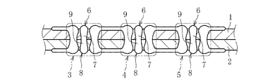
以上のように溶接電極11の移動軌跡と通電条件を設定してアーク溶接を施すことにより、各接合予定領域3〜5内に溶融部6が形成されると共に、第一の板状部材1から第二の板状部材2に至る深さの溶け込み部7が形成される(図4)。この場合、各接合予定領域3〜5内に形成される溶融部6は溶接電極11の移動軌跡(図2)に準じて蛇行した形状をなす。また、本実施形態では、接合予定領域3〜5内に形成される溶融部6が、第一の板状部材1を平面視した状態で、互いに重複しない位置に形成される。これにより溶け込み深さのばらつきなく極力均等な深さの溶け込み部7が接合予定領域3〜5内に形成される(図4)。
As described above, by setting the movement trajectory of the welding electrode 11 and the energization conditions and performing arc welding, the melted
このように、本発明では、溶接電極11を溶接予定領域3〜5上で蛇行させながらアーク溶接を行うようにしたので、各溶接予定領域3〜5に対する過度な加熱を防ぎつつ平面方向に大きなサイズの溶融部6(図2)を得ることができる。また、この際、適当な通電条件下での加熱溶融により適当な深さの溶け込み部7を得ることができる。よって、溶接予定領域3〜5に良好な接合部を形成して、所要の接合強度を得ることが可能となる。また、接合予定領域上への侵入位置と退出位置とが異なるように溶接電極を移動させることで、一の接合予定領域(図2でいえば最も左側の接合予定領域3)上からこれと隣り合う他の接合予定領域(図2でいえば真ん中の接合予定領域4)上へと、その軌跡が途切れることなく連続的に(いわば一筆書きの態様で)溶接電極11を移動させることができる。このような移動態様であれば、母材(第一の板状部材1)との間で発生させたアークを維持しながら順次隣り合う接合予定領域3〜5上に移動することができるので、その都度アーク放電を開始することなく各接合予定領域3〜5において板状部材1との間でアークを安定的に発生させることができる。よって、何れの接合予定領域3〜5においても安定した接合品質を得ることができる。また、その都度溶接電極を停止して、アークが安定するまで電流を流し続ける必要がないため、短時間でかつエネルギーコストを抑えてアーク溶接を実施することが可能となる。
In this way, in the present invention, arc welding is performed while meandering the welding electrode 11 on the planned
また、本実施形態では、溶接電極11が接合予定領域3〜5上を蛇行する際の移動軌跡が交差のない形状をなし、かつこれにより接合予定領域3〜5に形成された溶融部6が、板状部材1を平面視した状態で、互いに重複しない位置に形成されるようにした。これにより、既に第一の板状部材1に形成された溶融部6上に重複して新たな溶融部6が形成される事態を確実に回避することができる。よって、重複して溶融部6が形成されることによる溶け込み深さのばらつきをなくして、安定したサイズ(深さ)の溶け込み部7を形成することができ、これにより安定した接合品質を得ることが可能となる。
Moreover, in this embodiment, the welding locus | trajectory at the time of the welding electrode 11 meandering on the joining plan area | regions 3-5 makes a shape without an intersection, and the fusion | melting
以上、本発明の一実施形態を説明したが、本発明に係る接合方法は上記例示の形態に限定されることなく、本発明の範囲内において任意の形態を採り得ることはもちろんである。 Although one embodiment of the present invention has been described above, the joining method according to the present invention is not limited to the above-described exemplary form, and it is needless to say that any form can be adopted within the scope of the present invention.
例えば上記実施形態では、接合予定領域3〜5上における溶接電極11の移動軌跡として、略S字状に蛇行する形態を例示したが、必ずしもこの形態に限定される必要はない。設定すべき接合予定領域の形状に合わせて、当該接合予定領域に万遍なく溶融部を形成し得る限りにおいて、任意の形態を適用可能である。例えば図示は省略するが、侵入位置P1と退出位置P2を少しずらすことで略M字状に蛇行する移動軌跡をとることも可能である。 For example, in the said embodiment, although the form which meanders in a substantially S shape was illustrated as a movement locus | trajectory of the welding electrode 11 on the joining plan areas 3-5, it does not necessarily need to be limited to this form. Arbitrary forms can be applied as long as a melted portion can be uniformly formed in the planned joining region according to the shape of the planned joining region to be set. For example, although illustration is omitted, it is also possible to take a movement locus that meanders in a substantially M shape by slightly shifting the entry position P1 and the exit position P2.
また、上記実施形態では、移動時間(作業時間)の短縮のために、隣り合う接合予定領域3〜5間を溶接電極11が直線的に移動する軌跡が例示されているが、もちろんこの態様に限定される必要はなく、必要に応じて、例えば溶接対象となる板状部材の三次元形状に応じて曲線的に移動するようにしても構わない。 Moreover, in the said embodiment, in order to shorten moving time (working time), the locus | trajectory in which the welding electrode 11 moves linearly between the adjacent joining plan areas 3-5 is illustrated, but of course, in this aspect. It does not need to be limited, and may be moved in a curve according to the three-dimensional shape of the plate-like member to be welded, for example, as necessary.
また、上記実施形態では、一方の板状部材(第一の板状部材1)の側からのみアーク溶接を施して接合部を形成した場合を説明したが、例えば重ね合わせた複数の板状部材の表裏両側から上述した態様のアーク溶接を施すことも可能である。図5はこの場合に形成された接合部の断面形状を示している。このように、第一の板状部材1の側からだけでなく第二の板状部材2の側からも、上述した蛇行態様及び通電条件でアーク溶接を施すことで、図5に示すように、第二の板状部材2の側からも接合予定領域3〜5に溶融部8が形成される。また、第二の板状部材2から第一の板状部材1に至る深さの溶け込み部7が形成される。これにより、双方の溶け込み部7,9が板状部材1,2の厚み方向中央でつながるので、より強固な接合部を形成することが可能となる。
Moreover, in the said embodiment, although the case where the arc welding was performed only from the side of one plate-shaped member (1st plate-shaped member 1) and the junction part was formed was demonstrated, the several plate-shaped member overlap | superposed, for example It is also possible to perform arc welding in the above-described manner from both the front and back sides. FIG. 5 shows the cross-sectional shape of the joint formed in this case. As shown in FIG. 5, arc welding is performed not only from the first plate-
なお、以上の説明では何れも2枚の板状部材を接合する場合を例に挙げたが、もちろん本発明は、3枚以上の板状部材を接合する場合にも好適に適用可能である。 In the above description, the case where two plate members are joined is taken as an example, but the present invention is of course applicable to the case where three or more plate members are joined.
また、以上の説明では何れも複数の板状部材の板厚が等しい場合を例に挙げたが、もちろん板厚比の互いに異なる複数の板状部材を接合する場合にも好適に適用可能である。 Further, in the above description, the case where the plate thicknesses of the plurality of plate-like members are equal is given as an example, but of course, the present invention can also be suitably applied to the case of joining a plurality of plate-like members having different plate thickness ratios. .
また、以上の説明では、アーク溶接のみで各種接合部を形成する場合を例示したが、もちろん、他の接合手段(抵抗スポット溶接、従来公知のアーク溶接など)と併用することも可能である。 Moreover, although the case where various joints are formed only by arc welding is illustrated in the above description, it is of course possible to use in combination with other joining means (resistance spot welding, conventionally known arc welding, etc.).
また、以上の説明における板状部材は少なくとも接合予定領域において板状(重ね合わせ可能な形状)をなしていればよく、その他の部位の形状は問わない。また、その適用対象についても任意であり、車体構成部品はもちろん、他の構造体構成部品も本発明を適用することは可能である。 Moreover, the plate-shaped member in the above description should just be plate-shaped (shape which can be overlap | superposed) at least in the joining plan area | region, and the shape of another site | part does not ask | require. Further, the application target is also arbitrary, and the present invention can be applied to other structural body components as well as vehicle body components.
1,2 板状部材
3〜5 接合予定領域
6,8 溶融部
7,9 溶け込み部
10 溶接用トーチ
11 溶接電極
DESCRIPTION OF
Claims (3)
前記各々の接合予定領域上で前記溶接電極を蛇行させると共に、前記接合予定領域上への侵入位置と前記接合予定領域上からの退出位置とが異なるように前記溶接電極を移動させる、板状部材の接合方法。 A method for joining the plurality of plate-like members by sequentially performing arc welding on a plurality of joining scheduled regions while moving the welding electrodes along the planar direction of the plurality of plate-like members superimposed,
A plate-like member that causes the welding electrode to meander on each of the planned joining regions, and moves the welding electrode so that an intrusion position on the planned joining region and a withdrawal position from the planned joining region are different. Joining method.
Priority Applications (1)
| Application Number | Priority Date | Filing Date | Title |
|---|---|---|---|
| JP2014156570A JP2016032830A (en) | 2014-07-31 | 2014-07-31 | Joining method of plate-shaped member |
Applications Claiming Priority (1)
| Application Number | Priority Date | Filing Date | Title |
|---|---|---|---|
| JP2014156570A JP2016032830A (en) | 2014-07-31 | 2014-07-31 | Joining method of plate-shaped member |
Publications (1)
| Publication Number | Publication Date |
|---|---|
| JP2016032830A true JP2016032830A (en) | 2016-03-10 |
Family
ID=55451998
Family Applications (1)
| Application Number | Title | Priority Date | Filing Date |
|---|---|---|---|
| JP2014156570A Pending JP2016032830A (en) | 2014-07-31 | 2014-07-31 | Joining method of plate-shaped member |
Country Status (1)
| Country | Link |
|---|---|
| JP (1) | JP2016032830A (en) |
-
2014
- 2014-07-31 JP JP2014156570A patent/JP2016032830A/en active Pending
Similar Documents
| Publication | Publication Date | Title |
|---|---|---|
| CN109562474B (en) | joint structure | |
| JP5999293B1 (en) | Resistance spot welding method and resistance spot welding joint manufacturing method | |
| JP7656793B2 (en) | Laser Welding Method | |
| CN105149750B (en) | Method for bonding dissimilar metals to each other | |
| KR102207831B1 (en) | Point bonding device, point bonding method and joint structure | |
| KR101785229B1 (en) | Method for producing arc spot weld joint | |
| US20140008328A1 (en) | System and method for forming a joint with a hot wire | |
| JP2022062728A (en) | Welding method | |
| JP5261984B2 (en) | Resistance spot welding method | |
| JP6112209B2 (en) | Resistance spot welding method and manufacturing method of welded structure | |
| EP3132883B1 (en) | Laser welding method | |
| KR102622518B1 (en) | Resistance spot welding method and weld member production method | |
| US20220152736A1 (en) | Laser welding device and laser welding method | |
| JP2019136748A (en) | Resistance spot welding method | |
| JP6382593B2 (en) | Welding method | |
| JP5609966B2 (en) | Resistance spot welding method | |
| JP2016030283A (en) | Metallic member and method of manufacturing the same | |
| JP2012187616A (en) | Resistance welding apparatus and resistance welding method | |
| JP2016032830A (en) | Joining method of plate-shaped member | |
| JP2016030291A (en) | Method for joining plate-like members | |
| JP6123904B2 (en) | Resistance spot welding method and manufacturing method of welded structure | |
| JP2012250247A (en) | Resistance welding method, and method for manufacturing resistance welding structure | |
| JP5787302B2 (en) | Resistance welding method | |
| CN114473164A (en) | Resistance spot welding method for different metal workpiece stacked assembly and different metal stacked assembly for resistance spot welding | |
| KR102622519B1 (en) | Resistance spot welding method and weld member production method |