KR20160023466A - Fastener for fixing solar panel and fixing method using the same - Google Patents
Fastener for fixing solar panel and fixing method using the same Download PDFInfo
- Publication number
- KR20160023466A KR20160023466A KR1020140109919A KR20140109919A KR20160023466A KR 20160023466 A KR20160023466 A KR 20160023466A KR 1020140109919 A KR1020140109919 A KR 1020140109919A KR 20140109919 A KR20140109919 A KR 20140109919A KR 20160023466 A KR20160023466 A KR 20160023466A
- Authority
- KR
- South Korea
- Prior art keywords
- inclined portion
- fixing
- transverse
- solar panel
- fixing member
- Prior art date
- Legal status (The legal status is an assumption and is not a legal conclusion. Google has not performed a legal analysis and makes no representation as to the accuracy of the status listed.)
- Granted
Links
Images


Classifications
-
- H—ELECTRICITY
- H02—GENERATION; CONVERSION OR DISTRIBUTION OF ELECTRIC POWER
- H02S—GENERATION OF ELECTRIC POWER BY CONVERSION OF INFRARED RADIATION, VISIBLE LIGHT OR ULTRAVIOLET LIGHT, e.g. USING PHOTOVOLTAIC [PV] MODULES
- H02S20/00—Supporting structures for PV modules
-
- Y—GENERAL TAGGING OF NEW TECHNOLOGICAL DEVELOPMENTS; GENERAL TAGGING OF CROSS-SECTIONAL TECHNOLOGIES SPANNING OVER SEVERAL SECTIONS OF THE IPC; TECHNICAL SUBJECTS COVERED BY FORMER USPC CROSS-REFERENCE ART COLLECTIONS [XRACs] AND DIGESTS
- Y02—TECHNOLOGIES OR APPLICATIONS FOR MITIGATION OR ADAPTATION AGAINST CLIMATE CHANGE
- Y02E—REDUCTION OF GREENHOUSE GAS [GHG] EMISSIONS, RELATED TO ENERGY GENERATION, TRANSMISSION OR DISTRIBUTION
- Y02E10/00—Energy generation through renewable energy sources
- Y02E10/50—Photovoltaic [PV] energy
Landscapes
- Photovoltaic Devices (AREA)
Abstract
본 발명은 태양광 패널 고정을 위한 고정 부재 및 이를 이용한 고정 방법에 관한 것이다.
본 발명의 일측면에 따르면, 단면을 기준으로 상협하광(上狹下廣)의 경사 상태를 갖는 제1 경사부; 상기 제1 경사부의 하단에 일체로 연결 형성되며, 단면을 기준으로 상광하협(上廣下狹)의 경사 상태를 갖는 제2 경사부; 상기 제2 경사부의 하단에 일체로 연결 형성되며, 단면을 기준으로 상협하광(上狹下廣)의 경사 상태를 갖는 제3 경사부; 상기 제3 경사부의 하단에 일체로 연결 형성되는 본체부; 및 상기 본체부의 하단에 일체로 연결 형성되며 소정의 대상체에 걸림 고정이 가능한 걸림 요소를 구비하도록 형성된 걸림부;를 포함하되, 탄성 변형이 가능한 소재로 형성되고, 탄성 변형에 의한 확장 상태와 축소 상태를 갖도록 적어도 상기 제1 경사부 및 이와 일체로 연결 형성된 제2 경사부에 절개부가 형성된 것을 특징으로 하는 고정 부재가 개시된다.The present invention relates to a fixing member for fixing a solar panel and a fixing method using the same.
According to an aspect of the present invention, there is provided a light emitting device including: a first inclined portion having a slant state of a vertically downward light with respect to a cross section; A second inclined portion integrally connected to a lower end of the first inclined portion and having an inclined upper surface inclined relative to a cross section; A third inclined portion integrally connected to a lower end of the second inclined portion and having a tilted state of a vertically downward light based on a cross section; A body portion integrally formed at a lower end of the third inclined portion; And an engaging part formed integrally with the lower end of the main body part and configured to have an engaging element that can be engaged with a predetermined object, wherein the engaging part is formed of a material capable of being elastically deformed, And a cut-out portion is formed in at least the first inclined portion and the second inclined portion integrally connected to the first inclined portion.
Description
본 발명은 태양광 패널 고정을 위한 고정 부재 및 이를 이용한 고정 방법에 관한 것으로서, 태양광 발전에 사용되는 복수의 솔라셀이 설치된 태양광 패널을 메인 프레임에 설치함에 있어서, 탄성 변형에 의한 확장 및 축소가 가능한 고정 부재를 이용하여 설치 공정을 간편하게 구성함으로써, 공정에 소요되는 시간 및 인력을 절감할 수 있도록 구성된 태양광 패널 고정을 위한 고정 부재 및 이를 이용한 고정 방법에 관한 것이다.
BACKGROUND OF THE INVENTION 1. Field of the Invention [0001] The present invention relates to a fixing member for fixing a solar panel and a fixing method using the fixing member. In the solar panel having a plurality of solar cells used for solar power generation, The present invention relates to a fixing member for fixing a solar panel and a fixing method using the fixing member, which is configured to reduce the time and manpower required for the process by easily configuring the installation process using the fixing member.
화석 연료의 고갈과 함께, 태양광이나 풍력, 조력, 파력과 같은 대체 에너지 자원을 전력 생산에 활용하고자 하는 시도가 확산되고 있다. Along with depletion of fossil fuels, attempts have been made to utilize alternative energy sources such as solar, wind, tidal, and wave power for power generation.
이중에서 태양광 발전은 솔라셀(태양 전지)과 축전지, 전력변환장치 등의 요소를 이용하여 태양광으로부터 제공되는 광 에너지를 P형 반도체와 N형 반도체로 이뤄진 솔라셀의 전기 에너지로 변환하여 전력을 생산하는 발전 방식으로서, 공해가 없고, 설비의 유지보수가 용이하며, 다른 대체 에너지 자원에 비해 비교적 설치 지역의 제약이 적다는 장점으로 인해 그 이용이 확산되고 있다.
Among them, photovoltaic power generation uses solar cell (solar cell), battery, and power conversion device to convert the optical energy provided by solar light into electric energy of solar cell composed of P type semiconductor and N type semiconductor, Is widely used because it has no pollution, is easy to maintain and repair, and has relatively few restrictions on installation area compared to other alternative energy sources.
도 1은 종래의 일반적인 태양광 패널의 설치 구조를 예시한 사시도이다. 1 is a perspective view illustrating a conventional solar panel installation structure.
도면을 참조하면, 태양광 발전 설비는 다수개의 솔라셀(16)이 격자형으로 메인 패널(14)에 부착된 태양광 패널(10)을 태양의 이동 방향을 향해 경사 설치된 메인 프레임(20) 상에 고정 설치하고, 각 솔라셀(16)을 전력변환장치(도면 미도시)에 전기적으로 연결하는 방식으로 구성된다. 메인 패널(14)은 예를 들어, 아크릴 패널 등으로 형성될 수 있다. Referring to the drawings, a photovoltaic power generation facility includes a
메인 프레임(20)은 예를 들어, 4개의 수직 지지대(22) 상에 종방향 가로 지지대(24,26)와 이를 상호 연결하는 횡방향 가로 지지대(도면 미도시)가 기구적 체결 또는 용접 등을 통해 결합된 구조를 가지며, 태양의 이동 방향을 향해 경사지도록 설치된다. The
메인 프레임(20)의 종방향 가로 지지대(24,26)의 상부에 태양광 패널(10)이 얹혀지는 형태로 설치되어, 태양광 패널(10)이 태양의 이동 방향을 향한 상태로 고정 설치된다.
The
도 2는 도 1의 태양광 패널을 메인 프레임에 고정 설치한 상태를 나타낸 부분 단면도이다. 설명의 편의 상, 도 2는 종방향 가로 지지대(24,26) 중에서 특히, 좌측 종방향 가로 지지대(24)와 그 위에 설치된 태양광 패널(10)의 일부를 확대 단면도 형태로 도시하였다. FIG. 2 is a partial cross-sectional view showing a state in which the solar panel of FIG. 1 is fixed to a main frame. For ease of explanation, FIG. 2 shows, in enlarged cross-sectional view, a portion of the
도시된 고정 설치 구조를 보면, 종래의 일반적인 종방향 가로 지지대(24)는 상부를 향해 개방되고 내부에 공간이 형성된 대략 'ㄷ'자 형태의 채널 빔 형태를 가지며, 상부 개방 측에 단턱부(24b)와 볼트 관통구(24a)를 갖도록 구성된다. 또한, 볼트 관통구(24a)의 상단부는 측면으로 더욱 확장되어 상기 확장된 상단부에 태양광 패널(10)의 패널 프레임(12)이 얹혀진 상태로 지지 가능하도록 구성된다. 볼트 관통구(24a)는 종방향 가로 지지대(24)의 길이 방향을 따라 길게 연장 형성된다. 볼트(30) 머리는 상기 단턱부(24b)에 의해 걸림 지지된다. In the fixed installation structure shown in the drawing, the conventional general longitudinal
한편, 종래의 일반적인 태양광 패널(10)의 패널 프레임(12)은 도시된 바와 같이, 대략 'ㄷ'자 형태의 채널 빔 형태를 가지며, 하부측에 볼트 관통공(12a)이 일정 간격으로 형성된다. 패널 프레임(12)의 'ㄷ'자 형태의 상부면에는 예를 들어, 도시된 형태로 메인 패널(14)이 고정되며, 'ㄷ'자 형태의 하부면에 후술하는 바와 같이 메인 프레임(20)의 종방향 가로 지지대(24,26)가 고정 결합된다. As shown in the drawing, the
태양광 패널(10) 조립을 위해, 종방향 가로 지지대(24)의 볼트 관통구(24a)를 따라 일정 간격으로 볼트(30)가 구비되며, 상기 볼트(30)는 종방향 가로 지지대(24)의 내부 공간에 수직으로 마련된 스프링(34)을 통해 상방향으로 돌출되도록 탄성 지지된다.
종래에는 예를 들어, 상기와 같이 종방향 가로 지지대(24)의 볼트 관통구(24a)를 따라 일정 간격으로 볼트(30)가 구비된 상태에서, 상기 각각의 볼트(30)에 태양광 패널(10)의 패널 프레임(12)의 하부측 볼트 관통공(12a)이 관통된 상태로 태양광 패널(10)을 메인 프레임(20)의 종방향 가로 지지대(24,26) 상에 얹고, 패널 프레임(12) 'ㄷ'자 형 내부 공간 내에 작업자가 손이나 공구를 집어 넣어 너트(32)를 체결하는 방식으로 태양광 패널(10)을 조립하였다. The
이러한 방식은, 패널 프레임(12)의 좁은 'ㄷ'자 형 내부 공간 내에 작업자가 손이나 공구를 집어 넣어 작업을 해야 하기 때문에, 작업의 불편함과 함께 작업 시간의 효율성과 비용 면에서 대단히 불리한 요인이 되었다.
This method requires an operator to insert a hand or a tool into a narrow " C " shaped internal space of the
본 발명은 상기와 같은 종래의 문제점을 감안하여 안출된 것으로서, 태양광 발전에 사용되는 복수의 솔라셀이 설치된 태양광 패널을 메인 프레임에 설치함에 있어서, 탄성 변형에 의한 확장 및 축소가 가능한 고정 부재를 이용하여 설치 공정을 간편하게 구성함으로써, 공정에 소요되는 시간 및 인력을 절감할 수 있도록 구성된 태양광 패널 고정을 위한 고정 부재 및 이를 이용한 고정 방법을 제공하는 것을 그 목적으로 한다.
SUMMARY OF THE INVENTION It is an object of the present invention to provide a solar panel having a plurality of solar cells used for solar power generation in a main frame, The present invention provides a fixing member for fixing a solar panel and a fixing method using the fixing member, which can reduce the time and manpower required for the process.
상기 목적을 달성하기 위한 본 발명의 일측면에 따르면, 단면을 기준으로 상협하광(上狹下廣)의 경사 상태를 갖는 제1 경사부; 상기 제1 경사부의 하단에 일체로 연결 형성되며, 단면을 기준으로 상광하협(上廣下狹)의 경사 상태를 갖는 제2 경사부; 상기 제2 경사부의 하단에 일체로 연결 형성되며, 단면을 기준으로 상협하광(上狹下廣)의 경사 상태를 갖는 제3 경사부; 상기 제3 경사부의 하단에 일체로 연결 형성되는 본체부; 및 상기 본체부의 하단에 일체로 연결 형성되며 소정의 대상체에 걸림 고정이 가능한 걸림 요소를 구비하도록 형성된 걸림부;를 포함하되, 탄성 변형이 가능한 소재로 형성되고, 탄성 변형에 의한 확장 상태와 축소 상태를 갖도록 적어도 상기 제1 경사부 및 이와 일체로 연결 형성된 제2 경사부에 절개부가 형성된 것을 특징으로 하는 고정 부재가 개시된다.According to an aspect of the present invention, there is provided a light emitting device comprising: a first inclined portion having an inclined state of a vertically lower light with respect to a cross section; A second inclined portion integrally connected to a lower end of the first inclined portion and having an inclined upper surface inclined relative to a cross section; A third inclined portion integrally connected to a lower end of the second inclined portion and having a tilted state of a vertically downward light based on a cross section; A body portion integrally formed at a lower end of the third inclined portion; And an engaging part formed integrally with the lower end of the main body part and configured to have an engaging element that can be engaged with a predetermined object, wherein the engaging part is formed of a material capable of being elastically deformed, And a cut-out portion is formed in at least the first inclined portion and the second inclined portion integrally connected to the first inclined portion.
바람직하게 본 발명은, 상기 본체부와 제3 경사부의 내부에는 상기 절개부와 연결된 중공부가 길이 방향을 따라 형성되고, 상기 본체부의 일측면에는 장공이 형성되며, 상기 중공부의 내부 상측에는 하부의 스프링에 의해 탄지되어 상측으로 가압력을 제공하되, 상기 장공을 통해 외부로 돌출된 제1 조정핀에 의해 상하 이동이 가능한 제1 조정편이 구비된 것을 특징으로 한다. Preferably, in the present invention, a hollow portion connected to the incision portion is formed in the body portion and the third inclined portion along a longitudinal direction, a long hole is formed in one side of the body portion, And a first adjustment piece capable of moving up and down by a first adjustment pin protruding outward through the slot is provided.
바람직하게 본 발명은, 상기 본체부와 걸림부의 내부에는 길이 방향을 따라 중공부가 형성되고, 상기 본체부의 일측면에는 장공이 형성되며, 상기 중공부의 내부 하측에는 상부의 스프링에 의해 탄지되어 하측으로 가압력을 제공하되, 상기 장공을 통해 외부로 돌출된 제2 조정핀에 의해 상하 이동이 가능한 제2 조정편이 구비된 것을 특징으로 한다. Preferably, in the present invention, a hollow portion is formed along the longitudinal direction in the main body portion and the engaging portion, a long hole is formed in one side of the main body portion, a lower pressing force is applied to the lower portion of the hollow portion by a spring, And a second adjusting piece which is vertically movable by a second adjusting pin protruding outward through the slot is provided.
바람직하게, 상기 걸림부는 적어도 상하 방향의 이동을 제한하는 걸림턱 기능을 제공하는 걸림 요소를 구비한 것을 특징으로 한다. Preferably, the latching portion is provided with a latching element for providing a latching function of restricting movement in at least a vertical direction.
본 발명의 또다른 일측면에 따르면, 일측을 향해 경사진 빔(beam) 형상의 종방향 가로 지지대 및 상기 종방향 가로 지지대와 다른 지지 방향을 갖도록 형성된 빔 형상의 횡방향 가로 지지대가 수직 지지대 상에 설치된 메인 프레임을 마련하고, 상기 고정 부재를 이용하여, 패널 프레임을 지지 요소로 구비한 태양광 패널을 상기 메인 프레임 상에 고정하는 방법으로서, 상기 가로 지지대 또는 상기 패널 프레임 중 일측 요소의 지지면에 길이 방향을 따라 적어도 하나의 체결공을 마련하는 단계; 상기 체결공이 형성된 지지면에 대향하는 타측 요소의 지지면에 상기 고정 부재를 적어도 하나 이상 결합하는 단계; 및 상기 가로 지지대 상측에 상기 태양광 패널을 위치시킨 상태에서, 상기 가로 지지대 또는 상기 패널 프레임 중 일측 요소에 마련된 체결공에 타측 요소의 상기 고정 부재가 탄성 변형을 통해 관통됨과 함께 걸림이 이뤄지도록 결합하는 단계;를 포함하여 구성된 태양광 패널의 고정 방법이 개시된다.
According to another aspect of the present invention, there is provided a vertical support structure including a beam-shaped longitudinal transverse support tilted toward one side and a beam-shaped transverse transverse support formed to have a support direction different from the longitudinal transverse support, A method of fixing a solar panel having a panel frame as a supporting element on the main frame by providing an installed main frame and using the fixing member to fix the solar panel on the supporting frame Providing at least one fastening hole along the longitudinal direction; Coupling at least one of the fixing members to a supporting surface of the other element opposite to the supporting surface on which the fastening hole is formed; And the fixing member of the other element penetrates through the fixing hole provided in one of the transverse supporting members or the panel frame through elastic deformation while the solar panel is positioned on the upper side of the transverse supporting member, A method of fixing a solar panel comprising the steps of:
이러한 본 발명은, 탄성 변형에 의한 확장 및 축소가 가능한 고정 부재를 이용하여 메인 프레임에 대한 태양광 패널의 설치 공정을 간편하게 구성함으로써, 설치 공정에 소요되는 시간 및 인력을 절감할 수 있다는 장점이 있다. The present invention has an advantage in that the time and manpower required for the installation process can be reduced by using a fixing member capable of expanding and contracting by elastic deformation to simplify the installation process of the solar panel to the main frame .
또한, 종래의 복잡한 볼트 체결 방식에 비해 간단한 사용자 조작만으로 고정 부재의 결합 또는 해제 조작이 가능하므로, 태양광 패널 설치를 위한 별도의 공구나 장치가 필요가 없다는 장점도 있다.
In addition, since the fixing member can be engaged or disengaged by a simple user operation as compared with the conventional complicated bolt fastening method, there is also an advantage that there is no need for a separate tool or apparatus for installing a solar panel.
도 1은 종래의 일반적인 태양광 패널의 설치 구조를 예시한 사시도,
도 2는 도 1의 태양광 패널을 메인 프레임에 고정 설치한 상태를 나타낸 부분 단면도,
도 3은 본 발명의 일실시예에 따른 태양광 패널의 고정 방법을 적용한 태양광 패널을 예시한 사시도,
도 4는 본 발명의 일실시예에 따른 태양광 패널의 고정 방법의 적용 상태를 나타낸 분해 사시도,
도 5a 내지 도 5d는 본 발명의 일실시예에 따른 태양광 패널 고정 부재를 이용한 태양광 패널 고정 과정을 나타낸 부분 단면도,
도 6은 본 발명의 일실시예에 따른 태양광 패널 고정 부재의 사시도,
도 7은 본 발명의 일실시예에 따른 태양광 패널 고정 부재의 분해 사시도이다. 1 is a perspective view illustrating a conventional solar panel installation structure,
FIG. 2 is a partial sectional view showing a state in which the solar panel of FIG. 1 is fixed to the main frame,
3 is a perspective view illustrating a solar panel to which a solar panel fixing method according to an embodiment of the present invention is applied,
FIG. 4 is an exploded perspective view showing an application state of a method for fixing a solar panel according to an embodiment of the present invention, FIG.
5A to 5D are partial cross-sectional views illustrating a solar panel fixing process using a solar panel fixing member according to an embodiment of the present invention;
6 is a perspective view of a solar panel fixing member according to an embodiment of the present invention,
7 is an exploded perspective view of a solar panel fixing member according to an embodiment of the present invention.
본 발명은 그 기술적 사상 또는 주요한 특징으로부터 벗어남이 없이 다른 여러가지 형태로 실시될 수 있다. 따라서, 본 발명의 실시예들은 모든 점에서 단순한 예시에 지나지 않으며 한정적으로 해석되어서는 안 된다.The present invention may be embodied in many other forms without departing from its spirit or essential characteristics. Accordingly, the embodiments of the present invention are to be considered in all respects as merely illustrative and not restrictive.
제1, 제2 등의 용어는 다양한 구성요소들을 설명하는데 사용될 수 있지만, 상기 구성요소들은 상기 용어들에 의해 한정되어서는 안 된다. 상기 용어들은 하나의 구성요소를 다른 구성요소로부터 구별하는 목적으로만 사용된다. 예를 들어, 본 발명의 권리 범위를 벗어나지 않으면서 제1 구성요소는 제2 구성요소로 명명될 수 있고, 유사하게 제2 구성요소도 제1 구성요소로 명명될 수 있다. 및/또는 이라는 용어는 복수의 관련된 기재된 항목들의 조합 또는 복수의 관련된 기재된 항목들 중의 어느 항목을 포함한다.The terms first, second, etc. may be used to describe various components, but the components should not be limited by the terms. The terms are used only for the purpose of distinguishing one component from another. For example, without departing from the scope of the present invention, the first component may be referred to as a second component, and similarly, the second component may also be referred to as a first component. And / or < / RTI > includes any combination of a plurality of related listed items or any of a plurality of related listed items.
어떤 구성요소가 다른 구성요소에 "연결되어" 있다거나 "접속되어" 있다고 언급된 때에는, 그 다른 구성요소에 직접적으로 연결되어 있거나 또는 접속되어 있을 수도 있지만, 중간에 다른 구성요소가 존재할 수도 있다고 이해되어야 할 것이다. 반면에, 어떤 구성요소가 다른 구성요소에 "직접 연결되어" 있다거나 "직접 접속되어" 있다고 언급된 때에는, 중간에 다른 구성요소가 존재하지 않는 것으로 이해되어야 할 것이다.It is to be understood that when an element is referred to as being "connected" or "connected" to another element, it may be directly connected or connected to the other element, . On the other hand, when an element is referred to as being "directly connected" or "directly connected" to another element, it should be understood that there are no other elements in between.
본 출원에서 사용한 용어는 단지 특정한 실시예를 설명하기 위해 사용된 것으로, 본 발명을 한정하려는 의도가 아니다. 단수의 표현은 문맥상 명백하게 다르게 뜻하지 않는 한, 복수의 표현을 포함한다. 본 출원에서, "포함하다" 또는 "구비하다", "가지다" 등의 용어는 명세서상에 기재된 특징, 숫자, 단계, 동작, 구성요소, 부품 또는 이들을 조합한 것이 존재함을 지정하려는 것이지, 하나 또는 그 이상의 다른 특징들이나 숫자, 단계, 동작, 구성요소, 부품 또는 이들을 조합한 것들의 존재 또는 부가 가능성을 미리 배제하지 않는 것으로 이해되어야 한다.The terminology used in this application is used only to describe a specific embodiment and is not intended to limit the invention. The singular expressions include plural expressions unless the context clearly dictates otherwise. In the present application, the terms "comprises", "having", "having", and the like are intended to specify the presence of stated features, integers, steps, operations, components, Steps, operations, elements, components, or combinations of elements, numbers, steps, operations, components, parts, or combinations thereof.
다르게 정의되지 않는 한, 기술적이거나 과학적인 용어를 포함해서 여기서 사용되는 모든 용어들은 본 발명이 속하는 기술 분야에서 통상의 지식을 가진 자에 의해 일반적으로 이해되는 것과 동일한 의미를 가지고 있다. 일반적으로 사용되는 사전에 정의되어 있는 것과 같은 용어들은 관련 기술의 문맥상 가지는 의미와 일치하는 의미를 가지는 것으로 해석되어야 하며, 본 출원에서 명백하게 정의하지 않는 한, 이상적이거나 과도하게 형식적인 의미로 해석되지 않는다.Unless defined otherwise, all terms used herein, including technical or scientific terms, have the same meaning as commonly understood by one of ordinary skill in the art to which this invention belongs. Terms such as those defined in commonly used dictionaries are to be interpreted as having a meaning consistent with the contextual meaning of the related art and are to be interpreted as either ideal or overly formal in the sense of the present application Do not.
이하, 첨부된 도면을 참조하여 본 발명에 따른 바람직한 실시예를 상세히 설명하되, 도면 부호에 관계없이 동일하거나 대응하는 구성 요소는 동일한 참조 번호를 부여하고 이에 대한 중복되는 설명은 생략하기로 한다. 본 발명을 설명함에 있어서 관련된 공지 기술에 대한 구체적인 설명이 본 발명의 요지를 흐릴 수 있다고 판단되는 경우 그 상세한 설명을 생략한다.
Hereinafter, preferred embodiments of the present invention will be described in detail with reference to the accompanying drawings, wherein like or corresponding elements are denoted by the same reference numerals, and a duplicate description thereof will be omitted. DETAILED DESCRIPTION OF THE PREFERRED EMBODIMENTS Hereinafter, the present invention will be described in detail with reference to the accompanying drawings.
본 발명은, 태양광 발전에 사용되는 복수의 솔라셀이 설치된 태양광 패널을 메인 프레임에 설치함에 있어서, 탄성 변형에 의한 확장 및 축소가 가능한 고정 부재를 이용하여 설치 공정을 간편하게 구성함으로써, 공정에 소요되는 시간 및 인력을 절감할 수 있도록 구성된다. 이하, 도면을 참조하여 본 발명의 바람직한 일실시예를 설명한다.
The present invention provides a solar panel provided with a plurality of solar cells for use in solar power generation in a main frame, in which the installation process can be simplified by using a fixing member capable of expanding and contracting by elastic deformation, It is configured to save time and manpower. Hereinafter, a preferred embodiment of the present invention will be described with reference to the drawings.
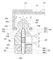
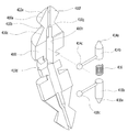
도 6은 본 발명의 일실시예에 따른 태양광 패널 고정 부재의 사시도, 도 7은 본 발명의 일실시예에 따른 태양광 패널 고정 부재의 분해 사시도이다. 도 5a 내지 도 5d는 본 발명의 일실시예에 따른 태양광 패널 고정 부재를 이용한 태양광 패널 고정 과정을 나타낸 부분 단면도이다. FIG. 6 is a perspective view of a solar panel fixing member according to an embodiment of the present invention, and FIG. 7 is an exploded perspective view of a solar panel fixing member according to an embodiment of the present invention. 5A to 5D are partial cross-sectional views illustrating a solar panel fixing process using a solar panel fixing member according to an embodiment of the present invention.
본 실시예의 고정부재는, 기본 구성으로서, 상측으로부터 하측으로 제1 경사부(410a) 및 제2 경사부(410b), 제3 경사부(410c), 본체부(410m), 걸림부(410d)가 일체로 연결 형성되며, 바람직한 일예로서 원형의 단면 형상을 갖도록 구성된다. The fixing member of this embodiment has a first
상기 제1 경사부(410a)는, 단면을 기준으로 상협하광(上狹下廣)의 경사 상태를 갖는다. The first
상기 제2 경사부(410b)는, 상기 제1 경사부(410a)의 하단에 일체로 연결 형성되며, 단면을 기준으로 상광하협(上廣下狹)의 경사 상태를 갖는다. The second
상기 제3 경사부(410c)는, 상기 제2 경사부(410b)의 하단에 일체로 연결 형성되며, 단면을 기준으로 상협하광(上狹下廣)의 경사 상태를 갖는다. The third
상기 본체부(410m)는, 상기 제3 경사부(410c)의 하단에 일체로 연결 형성되며, 바람직한 일예로서 원통과 유사한 형태로 형성된다. The
상기 걸림부(410d)는, 상기 본체부(410m)의 하단에 일체로 연결 형성되며 소정의 대상체에 걸림 고정이 가능한 걸림 요소를 구비하도록 형성된다. 바람직하게는, 상기 걸림부(410d)는 적어도 상하 방향의 이동을 제한하는 걸림턱 기능을 제공하는 걸림 요소를 구비한다. 본 실시예의 경우, 상기 걸림 요소는 대략 'T' 자형의 단면을 갖는 걸림턱의 형태로 형성된다. The
본 실시예의 고정부재는, 탄성 변형이 가능한 소재(예, 합성수지, 연성의 금속 소재)로 형성된다. The fixing member of this embodiment is formed of a material capable of being elastically deformed (e.g., a synthetic resin, a soft metal).
또한, 본 실시예의 고정부재는, 탄성 변형에 의한 확장 상태와 축소 상태를 갖도록 적어도 상기 제1 경사부(410a) 및 이와 일체로 연결 형성된 제2 경사부(410b)에 절개부(410f, 도 5a 참조)가 형성된다. In addition, the fixing member of the present embodiment is provided with at least the first
이러한 구성을 통해, 예를 들어, 도 3 및 도 4를 통해 후술하는 바와 같이, 고정 결합이 필요한 일측 요소에 상기 걸림부(410d)를 걸림 고정하고, 타측 요소에 상기 제1 경사부(410a)로부터 상기 제3 경사부(410c)에 이르는 경사부를 탄성 변형을 이용하여 관통(또는 압입) 고정하는 방식으로 일측 요소와 타측 요소를 상호 고정할 수 있다.
3 and 4, the latching
더욱 바람직한 일예로서, 본 실시예의 고정부재는, 상기 제1 경사부(410a)로부터 상기 제3 경사부(410c)에 이르는 경사부(410a~c)에 대하여 탄성 변형에 의한 확장 상태와 축소 상태를 더욱 용이하고 견고하게 구현하기 위한 구성을 더욱 구비할 수 있다. As a more preferable example, the fixing member of the present embodiment is configured such that the
이를 위해, 본 실시예의 고정부재에 있어서, 상기 본체부(410m)와 제3 경사부(410c)의 내부에는 상기 절개부(410f)와 연결된 중공부(410h)가 길이 방향을 따라 형성되고, 상기 본체부(410m)의 일측면에는 장공(410i)이 형성되며, 상기 중공부(410h)의 내부 상측에는 하부의 스프링(416)에 의해 탄지되어 상측으로 가압력을 제공하되, 상기 장공(410i)을 통해 외부로 돌출된 제1 조정핀(414c)에 의해 상하 이동이 가능한 제1 조정편(414)이 구비된다. 스프링(416)은 상기 제1 조정편(414)의 하단부와 후술하는 제2 조정편(418)의 상단부 사이에 위치되어 양측에 탄지력을 제공할 수 있다. In order to achieve this, in the fixing member of the present embodiment, a
이러한 구성을 통해, 본 실시예의 고정부재는, 상기 제1 조정핀(414c)이 상기 스프링(416)에 의해 탄지되어 상측으로 가압력을 제공하는 상태에서는 제1 조정편(414)의 원추형 첨단부(414a)가 상기 경사부(410a~c)의 절개부(410f) 내측에서 외측으로 가압력을 제공하여 상기 경사부(410a~c)가 탄성 변형에 의한 확장 상태를 이루게 되고, 사용자가 상기 제1 조정핀(414c)을 하측으로 눌러 제1 조정편(414)을 하측으로 이동시키는 경우 제1 조정편(414)의 첨단부(414a)가 함께 하측으로 이동되어 상기 경사부(410a~c)가 탄성 변형이 복원되어 축소 상태를 이루게 된다. With this configuration, the fixing member of the present embodiment is configured such that, when the
예를 들어, 상술한 바와 같이, 일측 요소에 상기 걸림부(410d)를 걸림 고정하고, 타측 요소에 상기 경사부(410a~c)를 탄성 변형을 이용하여 관통(또는 압입) 고정하는 경우에(도 5b 상태), 경사부(410a~c)를 관통(또는 압입)할 때에는 관통(또는 압입)이 더욱 용이하게 이뤄지도록 제1 조정핀(414c)을 하측으로 눌러 제1 조정편(414)을 하측으로 이동시킴으로써 경사부(410a~c)를 축소 상태로 만들고(도 5c 상태), 관통(또는 압입)이 된 후에 고정 결합을 완료하는 때에는 제1 조정핀(414c)의 누름 상태를 해제하여 제1 조정편(414)이 상측으로 이동함으로써 경사부(410a~c)를 확장 상태로 만들도록 할 수 있다(도 5d 상태). For example, as described above, when the engaging
한편, 상기 일측 요소와 타측 요소를 고장 수리 또는 교체 등을 위해 분리하고자 하는 경우에는, 상기의 조작과 반대 과정을 거쳐 분리 작업을 할 수 있다. Meanwhile, if the one-side element and the other side element are to be separated for repairing or replacing, it is possible to carry out the separating operation through the reverse process.
이러한 조작을 통해 본 실시예의 고정부재는, 경사부(410a~c)의 탄성 변형만을 이용하는 경우에 비해 더욱 편리하고 견고하게 고정 또는 분리 작업을 할 수 있도록 한다.
Through such operations, the fixing member of the present embodiment makes it possible to perform fixing or separation work more conveniently and firmly than when using only the elastic deformation of the
더욱 바람직한 일예로서, 본 실시예의 고정부재는, 상기 걸림부(410d)가 더욱 용이하고 견고하게 걸림 고정되기 위한 구성을 더욱 구비할 수 있다. As a more preferable example, the fixing member of the present embodiment may further include a structure for more easily and securely fastening the
이를 위해, 본 실시예의 고정부재는, 상기 본체부(410m)와 걸림부(410d)의 내부에는 길이 방향을 따라 중공부(410h)가 형성되고, 상기 본체부(410m)의 일측면에는 장공(410i)이 형성되며, 상기 중공부(410h)의 내부 하측에는 상부의 스프링(416)에 의해 탄지되어 하측으로 가압력을 제공하되, 상기 장공(410i)을 통해 외부로 돌출된 제2 조정핀(418c)에 의해 상하 이동이 가능한 제2 조정편(418)이 구비된다. For this purpose, the fixing member of the present embodiment has a
이러한 구성을 통해, 본 실시예의 고정부재는, 상기 제2 조정핀(418c)이 상기 스프링(416)에 의해 탄지되어 하측으로 가압되는 상태에서는 상기 중공부(410h)의 최하단부를 통해 제2 조정편(418)의 원추형 첨단부(418a)가 외부로 소정 길이만큼 돌출된 상태를 이루게 되고, 사용자가 상기 제2 조정핀(418c)을 상측으로 눌러 제2 조정편(418)을 상측으로 이동시키는 경우 제2 조정편(418)의 첨단부(418a)가 함께 상측으로 이동되어 돌출되지 않은 상태를 이루게 된다. With this configuration, the fixing member of the present embodiment is configured such that, when the
예를 들어, 상술한 바와 같이, 대략 'T' 자 단면형의 슬롯이 길이 방향을 따라 형성된 채널 빔(324)의 슬롯부(324b)에 상기 걸림부(410d)를 걸림 고정하는 경우에, 요구되는 고정 위치까지는 상기 제2 조정핀(418c)을 상측으로 눌러 제2 조정편(418)을 상측으로 이동시킨 상태(도 5a 상태)로 고정부재를 슬롯 내에서 슬라이딩 이동시키고(도 5a에서 지면에 수직인 방향으로 이동), 요구되는 고정 위치에 도달한 상태에서 상기 제2 조정핀(418c)의 누름 상태를 해제하여 제2 조정편(418)의 첨단부(418a)가 채널 빔(324)의 하단면에 형성된 관통구(324a)에 삽입 결합되어 견고한 설치 상태를 이루게 된다(도 5b 상태).
For example, as described above, when the engaging
한편, 본 실시예의 고정부재는, 상술한 기본 구성과 제1 조정편(414) 및/또는 제2 조정편(418)을 구비하는 구성이라면, 그 조립 구조는 조립 과정의 편의성과 제품의 견고함이 확보되는 범위에서 어느 하나의 조립 구조로 한정되는 것은 아니다. 예를 들어, 도 7의 분해 사시도는 장공(410i)을 중심으로 고정부재(410)가 좌우 양측으로 절단된 형상으로 표현되었지만, 반드시 이러한 절단 구조를 갖는 것으로 한정되지 않으며, 다양한 형태로 분해되도록 변형될 수 있다. 또한, 분해된 각 요소의 결합에 있어서도, 양측이 기구적 결합(예, 볼트 결합, 요홈부 압입식 결합, 외주부 결합링 결합 등)을 하거나, 물리/화학적 결합(예, 접착, 사출, 융착 등)을 하는 등 다양한 공지의 결합 방식이 적용될 수 있다. On the other hand, if the fixing member of the present embodiment has the above-described basic structure and the
또한, 도면에 예시된 고정부재는, 경사부(410a~c)가 4부분으로 절개된 것으로 예시되었지만, 2개 또는 그 이외의 개수로 절개될 수도 있다.
In addition, although the fixing member illustrated in the drawings is exemplified as the inclines 410a to 410c being cut into four parts, the fixing members may be cut into two or other numbers.
도 3은 본 발명의 일실시예에 따른 태양광 패널의 고정 방법을 적용한 태양광 패널을 예시한 사시도, 도 4는 본 발명의 일실시예에 따른 태양광 패널의 고정 방법의 적용 상태를 나타낸 분해 사시도이다. FIG. 3 is a perspective view illustrating a solar panel according to an embodiment of the present invention, and FIG. 4 is an exploded view illustrating a state of applying the method of fixing a solar panel according to an embodiment of the present invention. It is a perspective view.
일측을 향해 경사진 빔(beam) 형상의 종방향 가로 지지대(124,126) 및 상기 종방향 가로 지지대(124,126)와 다른 지지 방향을 갖도록 형성된 빔 형상의 횡방향 가로 지지대(128)가 수직 지지대(122) 상에 설치된 메인 프레임(120)을 마련하고, 상술한 고정 부재(410)를 이용하여, 패널 프레임(112)을 지지 요소로 구비한 태양광 패널(110)을 상기 메인 프레임(120) 상에 고정한다. Shaped longitudinal side supports 124 and 126 that are inclined toward one side and a beam shaped
우선, 상기 가로 지지대(124,126,128) 또는 상기 패널 프레임(112) 중 일측 요소의 지지면에 길이 방향을 따라 적어도 하나의 체결공(112a)을 마련한다. 본 실시예의 경우, 패널 프레임(112)에 체결공(112a)이 마련되며, 그 반대의 경우도 가능하다. At least one
바람직하게, 상기 체결공(112a)은 상기 고정 부재(410)의 경사부(410a~c)의 확장 상태일 때의 최외곽 직경보다는 작고, 경사부(410a~c)의 축소 상태일 때의 최외곽 직경보다는 같거나 작은 크기를 갖는 것이 바람직하다. 이러한 크기 조건일 때에 결합 과정이 용이하게 이뤄지고 결합 후에는 견고한 결합 상태가 확보될 수 있다. Preferably, the
다음으로, 상기 체결공(112a)이 형성된 지지면에 대향하는 타측 요소의 지지면에 상기 고정 부재(410)를 적어도 하나 이상 결합한다. 본 실시예의 경우, 상기 타측 요소는 가로 지지대(124,126)가 된다. 본 실시예의 가로 지지대(124,126)에는 대략 'T' 자 단면형의 슬롯이 길이 방향을 따라 형성된다. 예를 들어, 본 실시예의 가로 지지대(124,126)는 도 5a의 채널 빔(324)에 대응하는 것으로 이해될 수 있다. Next, at least one fixing
이때, 상술한 바와 같이, 걸림부(410d)를 이용한 결합이 이뤄지게 되며, 제2 조정편(418)을 이용하여 견고한 결합 상태를 얻을 수 있다. 상세한 결합 과정은 상술한 바 있으므로 중복 설명은 생략한다. At this time, as described above, the engagement using the
다음으로, 상기 가로 지지대(124,126,128) 상측에 상기 태양광 패널(110)을 위치시킨 상태에서, 상기 가로 지지대(124,126,128) 또는 상기 패널 프레임(112) 중 일측 요소에 마련된 체결공(112a)에 타측 요소의 상기 고정 부재(410)가 탄성 변형을 통해 관통됨과 함께 걸림이 이뤄지도록 결합한다. 이때, 상술한 바와 같이, 경사부(410a~c)의 확장 상태와 축소 상태의 탄성 변형을 이용한 결합이 이뤄지게 되며, 제1 조정편(414)을 이용하여 편리하고 견고한 결합 상태를 얻을 수 있다. 상세한 결합 과정은 상술한 바 있으므로 중복 설명은 생략한다.
Next, in a state in which the
본 발명은 첨부된 도면을 참조하여 바람직한 실시예를 중심으로 기술되었지만 당업자라면 이러한 기재로부터 본 발명의 범주를 벗어남이 없이 많은 다양하고 자명한 변형이 가능하다는 것은 명백하다. 따라서 본 발명의 범주는 이러한 많은 변형예들을 포함하도록 기술된 특허청구범위에 의해서 해석돼야 한다.
Although the present invention has been described with reference to the preferred embodiments thereof with reference to the accompanying drawings, it will be apparent to those skilled in the art that many other obvious modifications can be made therein without departing from the scope of the invention. Accordingly, the scope of the present invention should be interpreted by the appended claims to cover many such variations.
110: 태양광 패널
112: 패널 프레임
112a: 체결공
120: 메인 프레임
122: 수직 지지대
124,126: 종방향 가로 지지대
124a: 걸림편
128: 횡방향 가로 지지대
410: 고정부재
410a: 제1 경사부
410b: 제2 경사부
410c: 제3 경사부
410d: 걸림부
410f: 절개부
410h: 중공부
410i: 장공
410m: 본체부
414: 제1 조정편
416: 스프링
418: 제2 조정편110: solar panel 112: panel frame
112a: fastening ball 120: main frame
122:
124a: latching piece 128: transverse lateral support
410: fixing
410b: second
410d: fastening
410h:
410m: main body portion 414: first adjustment piece
416: spring 418: second adjustment piece
Claims (5)
상기 제1 경사부의 하단에 일체로 연결 형성되며, 단면을 기준으로 상광하협(上廣下狹)의 경사 상태를 갖는 제2 경사부;
상기 제2 경사부의 하단에 일체로 연결 형성되며, 단면을 기준으로 상협하광(上狹下廣)의 경사 상태를 갖는 제3 경사부;
상기 제3 경사부의 하단에 일체로 연결 형성되는 본체부; 및
상기 본체부의 하단에 일체로 연결 형성되며 소정의 대상체에 걸림 고정이 가능한 걸림 요소를 구비하도록 형성된 걸림부;를 포함하되,
탄성 변형이 가능한 소재로 형성되고,
탄성 변형에 의한 확장 상태와 축소 상태를 갖도록 적어도 상기 제1 경사부 및 이와 일체로 연결 형성된 제2 경사부에 절개부가 형성된 것을 특징으로 하는 고정 부재.
A first inclined portion having an inclined state of a vertically lowered light beam with respect to a cross section;
A second inclined portion integrally connected to a lower end of the first inclined portion and having an inclined upper surface inclined relative to a cross section;
A third inclined portion integrally connected to a lower end of the second inclined portion and having a tilted state of a vertically downward light based on a cross section;
A body portion integrally formed at a lower end of the third inclined portion; And
And a locking part formed integrally with a lower end of the main body part and configured to have a locking element that can be locked by a predetermined object,
And is formed of a material capable of elastic deformation,
Wherein an incision is formed in at least the first inclined portion and the second inclined portion integrally connected to the first inclined portion so as to have an expanded state and a reduced state due to elastic deformation.
상기 본체부와 제3 경사부의 내부에는 상기 절개부와 연결된 중공부가 길이 방향을 따라 형성되고,
상기 본체부의 일측면에는 장공이 형성되며,
상기 중공부의 내부 상측에는 하부의 스프링에 의해 탄지되어 상측으로 가압력을 제공하되, 상기 장공을 통해 외부로 돌출된 제1 조정핀에 의해 상하 이동이 가능한 제1 조정편이 구비된 것을 특징으로 하는 고정 부재.
The method according to claim 1,
A hollow portion connected to the cut-out portion is formed in the body portion and the third inclined portion along the longitudinal direction,
A long hole is formed in one side surface of the main body part,
And a first adjustment piece which is upwardly movable by a first adjustment pin protruding outward through the slot is provided on the upper side of the hollow part by being urged by a lower spring to provide a pressing force upwardly, .
상기 본체부와 걸림부의 내부에는 길이 방향을 따라 중공부가 형성되고,
상기 본체부의 일측면에는 장공이 형성되며,
상기 중공부의 내부 하측에는 상부의 스프링에 의해 탄지되어 하측으로 가압력을 제공하되, 상기 장공을 통해 외부로 돌출된 제2 조정핀에 의해 상하 이동이 가능한 제2 조정편이 구비된 것을 특징으로 하는 고정 부재.
3. The method of claim 2,
A hollow portion is formed along the longitudinal direction inside the body portion and the engaging portion,
A long hole is formed in one side surface of the main body part,
And a second adjustment piece provided on the inner lower side of the hollow portion by being biased by an upper spring to provide a pressing force downward and being movable up and down by a second adjustment pin protruding outward through the slot, .
상기 걸림부는 적어도 상하 방향의 이동을 제한하는 걸림턱 기능을 제공하는 걸림 요소를 구비한 것을 특징으로 하는 고정 부재.
The method according to claim 1,
Wherein the engaging portion is provided with a retaining element for providing a retaining jaw function for restricting movement in at least a vertical direction.
상기 가로 지지대 또는 상기 패널 프레임 중 일측 요소의 지지면에 길이 방향을 따라 적어도 하나의 체결공을 마련하는 단계;
상기 체결공이 형성된 지지면에 대향하는 타측 요소의 지지면에 상기 고정 부재를 적어도 하나 이상 결합하는 단계; 및
상기 가로 지지대 상측에 상기 태양광 패널을 위치시킨 상태에서, 상기 가로 지지대 또는 상기 패널 프레임 중 일측 요소에 마련된 체결공에 타측 요소의 상기 고정 부재가 탄성 변형을 통해 관통됨과 함께 걸림이 이뤄지도록 결합하는 단계;를 포함하여 구성된 태양광 패널의 고정 방법.A main frame provided on a vertical support with a beam-shaped longitudinal transverse supporter tilted toward one side and a beam-shaped transverse transverse supporter formed to have a different supporting direction from the transverse transverse supporter, A method for fixing a solar panel having a panel frame as a support element on the main frame using the fixing member according to any one of claims 1 to 4,
Providing at least one fastening hole along the longitudinal direction on the support surface of one of the transverse supports or the panel frame;
Coupling at least one of the fixing members to a supporting surface of the other element opposite to the supporting surface on which the fastening hole is formed; And
The fixing member of the other element penetrates through the fixing hole provided in one of the transverse supporting frame or the panel frame and is engaged so that the fixing is performed while the photovoltaic panel is positioned on the upper side of the transverse supporting frame A method of fixing a solar panel comprising:
Priority Applications (1)
| Application Number | Priority Date | Filing Date | Title |
|---|---|---|---|
| KR1020140109919A KR101705212B1 (en) | 2014-08-22 | 2014-08-22 | Fastener for fixing solar panel and fixing method using the same |
Applications Claiming Priority (1)
| Application Number | Priority Date | Filing Date | Title |
|---|---|---|---|
| KR1020140109919A KR101705212B1 (en) | 2014-08-22 | 2014-08-22 | Fastener for fixing solar panel and fixing method using the same |
Publications (2)
| Publication Number | Publication Date |
|---|---|
| KR20160023466A true KR20160023466A (en) | 2016-03-03 |
| KR101705212B1 KR101705212B1 (en) | 2017-02-09 |
Family
ID=55535451
Family Applications (1)
| Application Number | Title | Priority Date | Filing Date |
|---|---|---|---|
| KR1020140109919A Expired - Fee Related KR101705212B1 (en) | 2014-08-22 | 2014-08-22 | Fastener for fixing solar panel and fixing method using the same |
Country Status (1)
| Country | Link |
|---|---|
| KR (1) | KR101705212B1 (en) |
Cited By (3)
| Publication number | Priority date | Publication date | Assignee | Title |
|---|---|---|---|---|
| RU194244U1 (en) * | 2019-06-05 | 2019-12-04 | Общество с ограниченной ответственностью "Литейно-Прессовый Завод "Сегал" | Support table for mounting PV modules |
| KR102328212B1 (en) * | 2021-04-20 | 2021-11-18 | 제이케이엔지니어링(주) | Disaster-safe solar power generation structure with anti-departure and anti-seismic function of solar modules |
| CN114986462A (en) * | 2022-05-20 | 2022-09-02 | 青海黄河上游水电开发有限责任公司西宁太阳能电力分公司 | Photovoltaic module installs and removes device |
Citations (3)
| Publication number | Priority date | Publication date | Assignee | Title |
|---|---|---|---|---|
| KR101056531B1 (en) | 2011-06-22 | 2011-08-11 | 한광현 | Solar cell slim frame system |
| KR20130026223A (en) * | 2011-09-05 | 2013-03-13 | 유진기업 주식회사 | Composition for grinding of mineral containing sodium silicate hydrate |
| KR101411263B1 (en) * | 2013-12-24 | 2014-07-01 | 쏠라리버주식회사 | Appratus and method for installing solar photovoltaic power generation system |
-
2014
- 2014-08-22 KR KR1020140109919A patent/KR101705212B1/en not_active Expired - Fee Related
Patent Citations (3)
| Publication number | Priority date | Publication date | Assignee | Title |
|---|---|---|---|---|
| KR101056531B1 (en) | 2011-06-22 | 2011-08-11 | 한광현 | Solar cell slim frame system |
| KR20130026223A (en) * | 2011-09-05 | 2013-03-13 | 유진기업 주식회사 | Composition for grinding of mineral containing sodium silicate hydrate |
| KR101411263B1 (en) * | 2013-12-24 | 2014-07-01 | 쏠라리버주식회사 | Appratus and method for installing solar photovoltaic power generation system |
Cited By (3)
| Publication number | Priority date | Publication date | Assignee | Title |
|---|---|---|---|---|
| RU194244U1 (en) * | 2019-06-05 | 2019-12-04 | Общество с ограниченной ответственностью "Литейно-Прессовый Завод "Сегал" | Support table for mounting PV modules |
| KR102328212B1 (en) * | 2021-04-20 | 2021-11-18 | 제이케이엔지니어링(주) | Disaster-safe solar power generation structure with anti-departure and anti-seismic function of solar modules |
| CN114986462A (en) * | 2022-05-20 | 2022-09-02 | 青海黄河上游水电开发有限责任公司西宁太阳能电力分公司 | Photovoltaic module installs and removes device |
Also Published As
| Publication number | Publication date |
|---|---|
| KR101705212B1 (en) | 2017-02-09 |
Similar Documents
| Publication | Publication Date | Title |
|---|---|---|
| KR101705212B1 (en) | Fastener for fixing solar panel and fixing method using the same | |
| RU2710064C2 (en) | Furniture element and furniture fittings for connection of furniture parts | |
| US20160298668A1 (en) | Locking pin and grommet fastener assembly | |
| US20120097623A1 (en) | Hard disk drive holder | |
| RU2557747C1 (en) | Construction of sewing device | |
| US20170146050A1 (en) | Fastener structure for fixing assembly, fixing assembly, and method of assembling fixing assembly | |
| JP2010091111A (en) | Fastener and fastener assembly | |
| EP2669645A1 (en) | Clip for attaching battery temperature sensor | |
| CN106337861A (en) | Resilient Fastener | |
| US7614835B2 (en) | Simple fastening device | |
| US9125476B2 (en) | Clip assembly and electronic device including the same | |
| KR20160035225A (en) | A probe pin and the manufacturing methods of probe pin | |
| CN103032427B (en) | Latch components | |
| JP6851850B2 (en) | Sheet-shaped member fixture | |
| KR102103304B1 (en) | Apparatus for body coupling of solar panel | |
| KR20160023464A (en) | Fixing method for solar panel | |
| KR101806573B1 (en) | Nob and Lever Assembly | |
| US10064456B2 (en) | Zip slider structure | |
| KR101187944B1 (en) | Junction Box Fastening Device for Solar Cell Module | |
| US20140182103A1 (en) | Riveting apparatus | |
| CN106383552B (en) | Expansion seat with support component | |
| JP2007113707A (en) | Fixing device and fixing structure | |
| JP5295990B2 (en) | Fastener | |
| CN114551133B (en) | Jig for assembly | |
| US8233946B2 (en) | Electronic device with battery securing mechanism |
Legal Events
| Date | Code | Title | Description |
|---|---|---|---|
| A201 | Request for examination | ||
| PA0109 | Patent application |
St.27 status event code: A-0-1-A10-A12-nap-PA0109 |
|
| PA0201 | Request for examination |
St.27 status event code: A-1-2-D10-D11-exm-PA0201 |
|
| P11-X000 | Amendment of application requested |
St.27 status event code: A-2-2-P10-P11-nap-X000 |
|
| P13-X000 | Application amended |
St.27 status event code: A-2-2-P10-P13-nap-X000 |
|
| D13-X000 | Search requested |
St.27 status event code: A-1-2-D10-D13-srh-X000 |
|
| D14-X000 | Search report completed |
St.27 status event code: A-1-2-D10-D14-srh-X000 |
|
| E902 | Notification of reason for refusal | ||
| PE0902 | Notice of grounds for rejection |
St.27 status event code: A-1-2-D10-D21-exm-PE0902 |
|
| T11-X000 | Administrative time limit extension requested |
St.27 status event code: U-3-3-T10-T11-oth-X000 |
|
| E13-X000 | Pre-grant limitation requested |
St.27 status event code: A-2-3-E10-E13-lim-X000 |
|
| P11-X000 | Amendment of application requested |
St.27 status event code: A-2-2-P10-P11-nap-X000 |
|
| P13-X000 | Application amended |
St.27 status event code: A-2-2-P10-P13-nap-X000 |
|
| PG1501 | Laying open of application |
St.27 status event code: A-1-1-Q10-Q12-nap-PG1501 |
|
| E701 | Decision to grant or registration of patent right | ||
| PE0701 | Decision of registration |
St.27 status event code: A-1-2-D10-D22-exm-PE0701 |
|
| GRNT | Written decision to grant | ||
| PR0701 | Registration of establishment |
St.27 status event code: A-2-4-F10-F11-exm-PR0701 |
|
| PR1002 | Payment of registration fee |
St.27 status event code: A-2-2-U10-U11-oth-PR1002 Fee payment year number: 1 |
|
| PG1601 | Publication of registration |
St.27 status event code: A-4-4-Q10-Q13-nap-PG1601 |
|
| R18-X000 | Changes to party contact information recorded |
St.27 status event code: A-5-5-R10-R18-oth-X000 |
|
| R18-X000 | Changes to party contact information recorded |
St.27 status event code: A-5-5-R10-R18-oth-X000 |
|
| FPAY | Annual fee payment |
Payment date: 20200203 Year of fee payment: 4 |
|
| PR1001 | Payment of annual fee |
St.27 status event code: A-4-4-U10-U11-oth-PR1001 Fee payment year number: 4 |
|
| PR1001 | Payment of annual fee |
St.27 status event code: A-4-4-U10-U11-oth-PR1001 Fee payment year number: 5 |
|
| PR1001 | Payment of annual fee |
St.27 status event code: A-4-4-U10-U11-oth-PR1001 Fee payment year number: 6 |
|
| PC1903 | Unpaid annual fee |
St.27 status event code: A-4-4-U10-U13-oth-PC1903 Not in force date: 20230204 Payment event data comment text: Termination Category : DEFAULT_OF_REGISTRATION_FEE |
|
| PC1903 | Unpaid annual fee |
St.27 status event code: N-4-6-H10-H13-oth-PC1903 Ip right cessation event data comment text: Termination Category : DEFAULT_OF_REGISTRATION_FEE Not in force date: 20230204 |