KR102103304B1 - Apparatus for body coupling of solar panel - Google Patents
Apparatus for body coupling of solar panel Download PDFInfo
- Publication number
- KR102103304B1 KR102103304B1 KR1020180127254A KR20180127254A KR102103304B1 KR 102103304 B1 KR102103304 B1 KR 102103304B1 KR 1020180127254 A KR1020180127254 A KR 1020180127254A KR 20180127254 A KR20180127254 A KR 20180127254A KR 102103304 B1 KR102103304 B1 KR 102103304B1
- Authority
- KR
- South Korea
- Prior art keywords
- post
- fastening
- solar panel
- coupling portion
- support
- Prior art date
- Legal status (The legal status is an assumption and is not a legal conclusion. Google has not performed a legal analysis and makes no representation as to the accuracy of the status listed.)
- Active
Links
- 230000008878 coupling Effects 0.000 title claims description 44
- 238000010168 coupling process Methods 0.000 title claims description 44
- 238000005859 coupling reaction Methods 0.000 title claims description 44
- 238000010276 construction Methods 0.000 abstract description 4
- 230000000694 effects Effects 0.000 description 8
- 238000010248 power generation Methods 0.000 description 4
- 230000014509 gene expression Effects 0.000 description 3
- 230000005611 electricity Effects 0.000 description 2
- 230000000149 penetrating effect Effects 0.000 description 2
- 238000004904 shortening Methods 0.000 description 2
- 230000003111 delayed effect Effects 0.000 description 1
- 238000003912 environmental pollution Methods 0.000 description 1
- 239000002803 fossil fuel Substances 0.000 description 1
- 238000004519 manufacturing process Methods 0.000 description 1
- 238000000034 method Methods 0.000 description 1
- 238000012986 modification Methods 0.000 description 1
- 230000004048 modification Effects 0.000 description 1
- 230000001151 other effect Effects 0.000 description 1
- XLYOFNOQVPJJNP-UHFFFAOYSA-N water Substances O XLYOFNOQVPJJNP-UHFFFAOYSA-N 0.000 description 1
Images


Classifications
-
- E—FIXED CONSTRUCTIONS
- E04—BUILDING
- E04H—BUILDINGS OR LIKE STRUCTURES FOR PARTICULAR PURPOSES; SWIMMING OR SPLASH BATHS OR POOLS; MASTS; FENCING; TENTS OR CANOPIES, IN GENERAL
- E04H12/00—Towers; Masts or poles; Chimney stacks; Water-towers; Methods of erecting such structures
- E04H12/22—Sockets or holders for poles or posts
- E04H12/2253—Mounting poles or posts to the holder
- E04H12/2269—Mounting poles or posts to the holder in a socket
-
- H—ELECTRICITY
- H02—GENERATION; CONVERSION OR DISTRIBUTION OF ELECTRIC POWER
- H02S—GENERATION OF ELECTRIC POWER BY CONVERSION OF INFRARED RADIATION, VISIBLE LIGHT OR ULTRAVIOLET LIGHT, e.g. USING PHOTOVOLTAIC [PV] MODULES
- H02S20/00—Supporting structures for PV modules
- H02S20/30—Supporting structures being movable or adjustable, e.g. for angle adjustment
-
- Y—GENERAL TAGGING OF NEW TECHNOLOGICAL DEVELOPMENTS; GENERAL TAGGING OF CROSS-SECTIONAL TECHNOLOGIES SPANNING OVER SEVERAL SECTIONS OF THE IPC; TECHNICAL SUBJECTS COVERED BY FORMER USPC CROSS-REFERENCE ART COLLECTIONS [XRACs] AND DIGESTS
- Y02—TECHNOLOGIES OR APPLICATIONS FOR MITIGATION OR ADAPTATION AGAINST CLIMATE CHANGE
- Y02E—REDUCTION OF GREENHOUSE GAS [GHG] EMISSIONS, RELATED TO ENERGY GENERATION, TRANSMISSION OR DISTRIBUTION
- Y02E10/00—Energy generation through renewable energy sources
- Y02E10/50—Photovoltaic [PV] energy
Landscapes
- Engineering & Computer Science (AREA)
- Architecture (AREA)
- Civil Engineering (AREA)
- Structural Engineering (AREA)
- Roof Covering Using Slabs Or Stiff Sheets (AREA)
Abstract
Description
본 발명은 태양광 패널 체대 결합 장치에 관한 것으로, 보다 상세하게는 지주의 높이 조절이 가능한 태양광 패널 체대 결합 장치에 관한 것이다.The present invention relates to a solar panel body combining device, and more particularly, to a solar panel body combining device capable of adjusting the height of the prop.
최근 화석연료를 대체하면서도 환경오염 문제를 발생시키지 않는 청정에너지원인 태양광, 풍력, 조력을 이용한 친환경 발전설비의 시공이 점진적으로 증가하는 추세이다.Recently, construction of eco-friendly power generation facilities using solar, wind, and tidal power, which are clean energy sources that do not cause environmental pollution while replacing fossil fuels, is gradually increasing.
이러한 발전설비 중 태양광을 전기에너지로 변환하는 태양전지를 다수 어레이 시켜 발전을 하는 태양광 발전장치는 한 가구의 일일 사용 온수를 생성할 수 있을 정도의 전력을 생성할 수 있는 소규모에서 발전 전력량을 더욱 늘릴 수 있게 대규모로 시설되고 있다.Among these power generation facilities, a solar power generation unit that generates electricity by arraying a large number of solar cells that convert sunlight into electrical energy generates electricity at a small scale that can generate enough power to generate hot water for daily use in a household. It is being installed on a large scale for further increase.
이와 같은 태양광 발전장치와 같이 발전용량에 따라 다수의 태양광 발전모듈을 직렬로 배치하여 시공하는바, 이 경우 태양광 발전모듈은 바닥면에 설치된 기초콘크리트에 태양광 발전모듈의 하부에 결합된 지주를 고정하여 설치하게 된다.Like this photovoltaic device, a number of photovoltaic modules are installed in series according to the power generation capacity. In this case, the photovoltaic module is coupled to the bottom of the photovoltaic module on the base concrete installed on the bottom surface. The prop is fixed and installed.
즉, 태양광 발전모듈을 구성하는 지주를 별도의 고정장치를 통해 기초콘크리트에 고정하게 된다.That is, the pillars constituting the solar power module are fixed to the foundation concrete through a separate fixing device.
그러나 이와 같은 고정장치는 일체로 형성되기 때문에 지주의 높이가 맞지 않을 경우 지주를 높이에 맞게 절단하거나 새로운 지주를 연결해야 한다는 불편함이 있다, 즉, 지주를 높이에 맞게 재시공함에 따라 공사기간이 지연된다는 치명적인 단점이 발생할 수 있다.However, since such a fixing device is integrally formed, there is an inconvenience in that if the height of the post does not match, it is inconvenient to cut the post to the height or connect a new post, that is, the construction period is delayed as the post is rebuilt to the height. This can lead to fatal drawbacks.
따라서, 지주의 높이를 신속하게 조절할 수 있는 고정장치가 필요한 실정이다.Therefore, there is a need for a fixing device capable of quickly adjusting the height of the post.
따라서, 종래의 문제점을 해결하기 위한 것으로, 본 발명은 지주의 높이를 신속하게 고정할 수 있는 태양광 패널 체대 결합 장치를 제공하기 위한 것이다.Therefore, to solve the problems of the prior art, the present invention is to provide a solar panel body coupling device capable of quickly fixing the height of the strut.
또한, 지주를 고정시키는 체결부재에 체결부재가 안착되는 홈이 형성되어, 체결부재와 지주가 더욱 견고하게 체결 가능한 태양광 패널 체대 결합 장치를 제공하는데 그 목적이 있다. In addition, it is an object to provide a solar panel body coupling device that is formed with a groove on which the fastening member is seated on the fastening member for fixing the strut, so that the fastening member and the strut can be more firmly fastened.
본 발명의 해결과제는 이상에서 언급한 것들에 한정되지 않으며, 언급되지 아니한 다른 해결과제들은 아래의 기재로부터 당업자에게 명확하게 이해될 수 있을 것이다.The problems of the present invention are not limited to those mentioned above, and other problems that are not mentioned will be clearly understood by those skilled in the art from the following description.
상기 본 발명의 목적들 및 다른 특징들을 달성하기 위한 본 발명의 태양광 패널 체대 결합 장치는 일측이 지면에 고정되고, 타측이 지면으로부터 직교하는 방향으로 연장 형성되는 지주 결합부; 일단이 태양광 패널과 연결되고, 타단이 상기 지주 결합 결합부의 타단에 삽입되어 상기 지주 결합부의 내부에서 길이방향으로 슬라이딩 이동되는 지주; 및 일단이 상기 지주 결합부의 외측에 회전 가능하게 설치되고, 회전 동작에 따라 타단이 상기 지주 결합부와 상기 지주를 관통하여 상기 지주를 예정된 높이에 고정시키는 체결부재를 포함할 수 있다.The photovoltaic panel body coupling device of the present invention for achieving the objects and other features of the present invention is fixed to one side of the ground, the other side of the post coupling formed extending in an orthogonal direction from the ground; One end is connected to the photovoltaic panel, the other end is inserted into the other end of the post coupling portion, the post is slidably moved in the longitudinal direction inside the post coupling portion; And one end is rotatably installed on the outside of the post coupling portion, the other end may include a fastening member for fixing the post at a predetermined height through the post coupling portion and the post according to the rotation operation.
본 발명에 있어서 상기 지주 결합부는, 상기 지면과 평행한 방향으로 형성되어 지면에 고정되는 지지판; 일단이 상기 지지판과 연결되고 타단이 상기 지지판으로부터 직교하는 방향으로 연장 형성되며, 내부가 중공의 관 형태로 형성되어 상기 지주가 슬라이딩 이동되는 지지몸체; 및 상기 지지몸체의 외측에 서로 대향하도록 관통 형성되는 한 쌍의 제1 체결공을 포함할 수 있다.In the present invention, the support coupling portion is formed in a direction parallel to the ground support plate fixed to the ground; A support body having one end connected to the support plate, the other end extending in an orthogonal direction from the support plate, and the inside formed in a hollow tube shape such that the posts are slid; And it may include a pair of first fastening holes that are formed to face each other on the outside of the support body.
본 발명에 있어서 상기 지주의 타단에는, 외측에 서로 대향하게 형성되는 한 쌍의 제2 체결공이 길이 방향을 따라 복수개 형성될 수 있다.In the present invention, at the other end of the support, a plurality of second fastening holes formed opposite to each other on the outside may be formed along the longitudinal direction.
본 발명에 있어서 상기 체결부재는, 일단이 상기 지주 결합부의 외측에 회전 가능하게 힌지 결합되고, 타단이 상기 지주 결합부의 길이방향을 향해 연장 형성되는 체결몸체; 및 일단이 상기 체결몸체의 타단에 연결되고 타단이 상기 지주 결합부의 내부를 향하도록 돌출 형성되는 체결턱을 포함하고, 상기 체결턱은, 체결몸체의 회전에 따라 상기 지주 결합부와 상기 지주를 순차적으로 관통하여 상기 지주를 상기 지주 결합부로부터 예정된 높이에 고정시킬 수 있다.In the present invention, the fastening member, one end is rotatably hinged to the outside of the post coupling portion, the other end of the fastening body is formed extending toward the longitudinal direction of the post coupling portion; And a fastening jaw having one end connected to the other end of the fastening body and protrudingly formed so that the other end faces the inside of the strut engaging portion, wherein the fastening jaw sequentially rotates the strut engaging portion and the strut according to the rotation of the fastening body. By passing through it can be fixed to the predetermined height from the holding post engaging portion.
본 발명에 있어서 상기 지주는 내부가 중공된 관 형태로 형성되고, 상기 체결턱의 상부에는, 상기 지주의 외주면과 대응하는 형상으로 형성되어 상기 지주의 관통된 상면이 안착되는 체결홈을 포함할 수 있다.In the present invention, the support is formed in a hollow tube shape, the upper portion of the fastening jaw is formed in a shape corresponding to the outer circumferential surface of the support may include a fastening groove on which the upper surface of the support is seated have.
본 발명에 있어서 상기 지지몸체에는, 내부 바닥면에 형성되고 상기 지주가 삽입될 때 지주에 가해지는 충격을 완화시키기 위한 충격방지부재를 포함할 수 있다.In the present invention, the support body, may be formed on the inner bottom surface and may include an impact preventing member for alleviating the impact applied to the post when the post is inserted.
본 발명에 따른 태양광 패널 체대 결합 장치는 다음과 같은 효과를 제공한다.The solar panel body combining device according to the present invention provides the following effects.
본 발명은 태양광 패널을 지지하는 복수개의 지주 높이가 다르더라도 지주를 고정하는 고정장치를 통해 지주의 높이를 손쉽게 조절할 수 있기 때문에 공사기간을 단축할 수 있는 효과가 있다.The present invention has the effect of shortening the construction period because the height of the pillar can be easily adjusted through a fixing device for fixing the pillar even if the height of the plurality of pillars supporting the solar panel is different.
특히, 본 발명은 지주를 고정시키는 체결부재에 체결부재가 안착되는 홈이 형성되기 때문에 체결부재와 지주가 더욱 견고하게 체결 가능한 효과가 있다.Particularly, the present invention has an effect that the fastening member and the strut can be more firmly fastened because a groove is formed in the fastening member for fixing the strut.
본 발명의 효과는 이상에서 언급된 것들에 한정되지 않으며, 언급되지 아니한 다른 효과들은 아래의 기재로부터 당업자에게 명확하게 이해될 수 있을 것이다.The effects of the present invention are not limited to those mentioned above, and other effects not mentioned will be clearly understood by those skilled in the art from the following description.
도 1은 본 발명의 실시예에 따른 태양광 패널 체대 결합 장치를 설명하기 위한 개략도 이다.
도 2는 본 발명의 실시예에 따른 태양광 패널 체대 결합 장치를 설명하기 위한 사시도 이다.
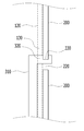
도 3은 본 발명의 실시예에 따른 태양광 패널 체대 결합 장치를 설명하기 위한 단면도 이다.
도 4는 본 발명의 실시예에 따른 태양광 패널 체대 결합 장치의 체결부재를 설명하기 위한 사시도 이다.
도 5는 본 발명의 다른 실시예에 따른 태양광 패널 체대 결합 장치를 설명하기 위한 사시도 이다.1 is a schematic view for explaining a solar panel body coupling device according to an embodiment of the present invention.
2 is a perspective view for explaining a solar panel body coupling device according to an embodiment of the present invention.
3 is a cross-sectional view illustrating a solar panel body coupling device according to an embodiment of the present invention.
4 is a perspective view for explaining a fastening member of the solar panel body coupling device according to an embodiment of the present invention.
5 is a perspective view for explaining a solar panel body coupling device according to another embodiment of the present invention.
본 발명에 관한 설명은 구조적 내지 기능적 설명을 위한 실시예에 불과하므로, 본 발명의 권리범위는 본문에 설명된 실시예에 의하여 제한되는 것으로 해석되어서는 아니 된다. 즉, 실시예는 다양한 변경이 가능하고 여러 가지 형태를 가질 수 있으므로 본 발명의 권리범위는 기술적 사상을 실현할 수 있는 균등물들을 포함하는 것으로 이해되어야 한다. 또한, 본 발명에서 제시된 목적 또는 효과는 특정 실시예가 이를 전부 포함하여야 한다거나 그러한 효과만을 포함하여야 한다는 의미는 아니므로, 본 발명의 권리범위는 이에 의하여 제한되는 것으로 이해되어서는 아니 될 것이다.Since the description of the present invention is merely an example for structural or functional description, the scope of the present invention should not be interpreted as being limited by the examples described in the text. That is, since the embodiments can be variously modified and have various forms, it should be understood that the scope of the present invention includes equivalents capable of realizing technical ideas. In addition, the object or effect presented in the present invention does not mean that a specific embodiment should include all of them or only such an effect, and the scope of the present invention should not be understood as being limited thereby.
한편, 본 출원에서 서술되는 용어의 의미는 다음과 같이 이해되어야 할 것이다.Meanwhile, the meaning of terms described in the present application should be understood as follows.
"제1", "제2" 등의 용어는 하나의 구성요소를 다른 구성요소로부터 구별하기 위한 것으로, 이들 용어들에 의해 권리범위가 한정되어서는 아니 된다. 예를 들어, 제1 구성요소는 제2 구성요소로 명명될 수 있고, 유사하게 제2 구성요소도 제1 구성요소로 명명될 수 있다.Terms such as "first" and "second" are for distinguishing one component from other components, and the scope of rights should not be limited by these terms. For example, the first component may be referred to as the second component, and similarly, the second component may also be referred to as the first component.
어떤 구성요소가 다른 구성요소에 "연결되어"있다고 언급된 때에는, 그 다른 구성요소에 직접적으로 연결될 수도 있지만, 중간에 다른 구성요소가 존재할 수도 있다고 이해되어야 할 것이다. 반면에, 어떤 구성요소가 다른 구성요소에 "직접 연결되어"있다고 언급된 때에는 중간에 다른 구성요소가 존재하지 않는 것으로 이해되어야 할 것이다. 한편, 구성요소들 간의 관계를 설명하는 다른 표현들, 즉 "~사이에"와 "바로 ~사이에" 또는 "~에 이웃하는"과 "~에 직접 이웃하는" 등도 마찬가지로 해석되어야 한다.When a component is said to be "connected" to another component, it may be understood that other components may exist in the middle, although they may be directly connected to the other component. On the other hand, when a component is said to be "directly connected" to another component, it should be understood that no other component exists in the middle. On the other hand, other expressions describing the relationship between the components, that is, "between" and "immediately between" or "neighboring to" and "directly neighboring to" should be interpreted similarly.
단수의 표현은 문맥상 명백히 다르게 뜻하지 않는 한 복수의 표현을 포함하는 것으로 이해되어야 하고, "포함하다" 또는 "가지다" 등의 용어는 실시된 특징, 숫자, 단계, 동작, 구성요소, 부분품 또는 이들을 조합한 것이 존재함을 지정하려는 것이며, 하나 또는 그 이상의 다른 특징이나 숫자, 단계, 동작, 구성요소, 부분품 또는 이들을 조합한 것들의 존재 또는 부가 가능성을 미리 배제하지 않는 것으로 이해되어야 한다.Singular expressions are to be understood as including plural expressions unless the context clearly indicates otherwise, and terms such as “comprises” or “have” are used features, numbers, steps, actions, elements, parts or the like. It is to be understood that a combination is intended to be present, and should not be understood as pre-excluding the existence or addition possibility of one or more other features or numbers, steps, actions, components, parts or combinations thereof.
각 단계들에 있어 식별부호(예를 들어, a, b, c 등)는 설명의 편의를 위하여 사용되는 것으로 식별부호는 각 단계들의 순서를 설명하는 것이 아니며, 각 단계들은 문맥상 명백하게 특정 순서를 기재하지 않는 이상 명기된 순서와 다르게 일어날 수 있다. 즉, 각 단계들은 명기된 순서와 동일하게 일어날 수도 있고 실질적으로 동시에 수행될 수도 있으며 반대의 순서대로 수행될 수도 있다.In each step, the identification code (for example, a, b, c, etc.) is used for convenience of explanation. The identification code does not describe the order of each step, and each step clearly identifies a specific order in context. Unless stated, it may occur in a different order than specified. That is, each step may occur in the same order as specified, may be performed substantially simultaneously, or may be performed in the reverse order.
여기서 사용되는 모든 용어들은 다르게 정의되지 않는 한, 본 발명이 속하는 분야에서 통상의 지식을 가진 자에 의해 일반적으로 이해되는 것과 동일한 의미를 가진다. 일반적으로 사용되는 사전에 정의되어 있는 용어들은 관련 기술의 문맥상 가지는 의미와 일치하는 것으로 해석되어야 하며, 본 출원에서 명백하게 정의하지 않는 한 이상적이거나 과도하게 형식적인 의미를 지니는 것으로 해석될 수 없다.All terms used herein have the same meaning as generally understood by a person skilled in the art to which the present invention pertains, unless otherwise defined. The terms defined in the commonly used dictionary should be interpreted as being consistent with the meanings in the context of the related art, and cannot be interpreted as having ideal or excessively formal meanings unless explicitly defined in the present application.
이하, 본 발명의 실시예에 따른 태양광 패널 체대 결합 장치에 대하여 도면을 참조하여 상세히 설명하기로 한다.Hereinafter, a solar panel body coupling device according to an embodiment of the present invention will be described in detail with reference to the drawings.
도 1은 본 발명의 실시예에 따른 태양광 패널 체대 결합 장치를 설명하기 위한 개략도 이고, 도 2는 본 발명의 실시예에 따른 태양광 패널 체대 결합 장치를 설명하기 위한 사시도 이고, 도 3은 본 발명의 실시예에 따른 태양광 패널 체대 결합 장치를 설명하기 위한 단면도 이다.1 is a schematic view for explaining a solar panel body coupling device according to an embodiment of the present invention, Figure 2 is a perspective view for explaining a solar panel body combining device according to an embodiment of the present invention, Figure 3 is a It is a sectional view for explaining a solar panel body coupling device according to an embodiment of the invention.
도 1 내지 도 3에 도시된 바와 같이, 본 발명의 실시예에 따른 태양광 패널 체대 결합 장치는 지면(G)에 고정되는 지주 결합부(100)와, 일단이 태양광 패널(10)과 연결되고 타단이 지주 결합부(100)와 연결되는 지주(200) 및 지주 결합부(100)와 지주(200)를 체결하는 체결부재(300)로 구성된다.1 to 3, the solar panel body coupling device according to an embodiment of the present invention is coupled to the
먼저, 지주(200)는 일단에 태양광 패널(10)과 연결되어, 태양광 패널(10)을 지면(G)으로부터 이격된 상태로 지지시키는 역할을 할 수 있다. 지주(200)의 타단은 후술할 지주 결합부(100)에 삽입된 상태로 지주 결합부(100)와 결합될 수 있다.First, the
지주(200)의 타단 외측에는 서로 대향하게 형성되는 제2 체결공(220)이 길이방향을 따라 복수개 형성될 수 있다. 제2 체결공(220)은 후술한 체결부재(300)가 관통될 수 있다. 지주(200)는 제2 체결공(220)에 관통되는 체결부재(300)에 의해서 지주 결합부(100)로부터 예정된 높이에 고정될 수 있다.A plurality of
예컨대, 지주(200)를 지주 결합부(100)에 결합할 때, 체결부재(300)가 복수의 제2 체결공(220) 중 체결되는 위치에 따라 지주 결합부(100)로부터 지주(200)의 높이가 조절될 수 있다.For example, when the
지주 결합부(100)는 일측이 지면(G)에 고정되고 타측이 지주(200)와 연결되어 지주(200)를 지면(G)으로부터 고정시키는 역할을 할 수 있다.The
이와 같은, 지주 결합부(100)는 지면(G)에 고정되는 지지판(110)이 형성될 수 있다. 지지판(110)은 지면(G)과 평행한 방향을 가지는 플레이트 형태로 형성되어 지면(G)에 배치된 후 고정부재(C)를 통해 지면(G)에 고정될 수 있다.As such, the
본 실시예에서 지면(G)은 기초콘크리트로 구성될 수 있으나 이에 한정하지 않는다.In this embodiment, the ground (G) may be composed of a basic concrete, but is not limited thereto.
본 실시예에서 고정부재(C)는 볼트 너트로 구성될 수 있으며, 또한 앙카 볼트로도 구성될 수 있으며, 이에 한정하지 않는다.In this embodiment, the fixing member (C) may be composed of a bolt nut, and may also be composed of an anchor bolt, but is not limited thereto.
지지판(110)의 상부에는 지지몸체(120)가 형성될 수 있다. 지지 몸체는 일단이 지지판(110)과 연결되고 타단이 지지판(110)으로부터 직교하는 방향으로 연장 형성될 수 있다. A
그리고, 지지몸체(120)는 내부가 중공의 관 형태로 형성되어 지주(200)의 일단이 삽입된 상태에서 길이 방향으로 슬라이딩 이동 가능할 수 있다. In addition, the
본 실시예에서 지지몸체(120)의 단면 형태는 지주(200)의 단면 형태와 대응하는 형태로 형성될 수 있으며, 지주(200)의 단면 형태에 따라서 원형 또는 다각의 단면 형태로 형성될 수 있다.In this embodiment, the cross-sectional shape of the
본 실시예에서 지지몸체(120)와 지지판(110)은 도면에 도시된 바와 같이 일체형으로 형성될 수 있으며, 각각 분리된 상태에서 볼트너트를 통해 체결될 수도 있다.In the present embodiment, the
지지몸체(120)에는 내부 바닥면에 형성되고 지주(200)가 삽입될 때 지주(200)에 가해지는 충격을 완화시키기 위한 충격방지부재(미도시)를 포함할 수 있다. 충격방지부재는 지주(200)가 지지몸체(120)의 내부에 삽입될 때 지주(200)와 지지몸체(120)의 충돌에 대한 충격을 완화시키는 역할을 할 수 있다.The
충격방지부재는 스프링을 포함할 수 있으며, 이에 한정하지 않는다. 예컨대 충격방지부재는 탄력성을 가지는 물체 어느것으로도 형성될 수 있다.The impact preventing member may include a spring, but is not limited thereto. For example, the impact preventing member may be formed of any object having elasticity.
지지몸체(120)의 외측에는 제1 체결공(130)이 관통 형성될 수 있다. 제1 체결공(130)은 지지몸체(120)의 외측에 서로 대향하도록 형성될 수 있으며, 제1 체결공(130)에는 후술할 체결부재(300)가 관통될 수 있다.A
제1 체결공(130)은 지지몸체(120)의 길이방향을 따라 소정의 길이로 연장 형성(예를 들어 장방형 또는 장원형)될 수 있으며, 제1 체결공(130)이 길이방향으로 따라 소정의 길이로 형성되는 이유는 아래에서 체결부재(300)를 설명할 때 다시 설명하기로 한다.The
한편, 지주 결합부(100)의 외측에는 체결부재(300)가 마련될 수 있다. 체결부재(300)는 지주 결합부(100)의 외측에 서로 대향하도록 한 쌍으로 마련될 수 있다. 체결부재(300)는 지주 결합부(100)로부터 지주(200)를 예정된 높이에 고정시키는 역할을 할 수 있다.On the other hand, the
지주(200)를 지주 결합부(100)로부터 예정된 높이에 고정시키기 위해 체결부재(300)는 체결몸체(310) 및 체결턱(320)으로 구성될 수 있다.The
체결몸체(310)는 일단이 지주 결합부(100)의 외측에 힌지부재(340)를 통해 회전 가능하게 설치되고 타단이 지주(200) 몸체의 길이 방향을 향해 연장 형성될 수 있다. 체결몸체(310)는 후술할 체결턱(320)을 이동시키는 역할을 할 수 있다. The
도면에 도시된 바와 같이, 힌지부재(340)의 위치는 지주(200)몸체에 형성된 제1 관통공보다 아래 방향으로 소정 간격 이격되어 형성될 수 있지만 힌지부재(340)의 위치는 어느 하나로 한정하지 않는다.As shown in the figure, the position of the
체결몸체(310)의 타단에는 체결턱(320)이 돌출 형성될 수 있다. 체결턱(320)은 일단 체결몸체(310)의 타단과 연결되고 타단이 지주(200)몸체의 내부를 향하도록 절곡되도록 돌출 형성될 수 있다. 예컨대 체결몸체(310)와 체결턱(320)으로 형성된 체결부재(300)는 'ㄱ' 형상으로 형성될 수 있다.A
그리고 체결턱(320)은 힌지부재(340)에 의한 체결몸체(310)의 회전 동작에 따라 지주 결합부(100)의 제1 체결공(130)과 지주(200)의 제2 체결공(220)을 순차적으로 관통하여 지주(200)를 지주(200) 몸체로부터 예정된 높이에 고정시키는 역할을 할 수 있다.In addition, the
일 예로, 체결턱(320)은 지주(200)와 체결될 때 복수의 제2 체결공(220) 중 체결되는 제2 체결공(220)의 높이에 따라서 지주 결합부(100)로부터 지주(200)의 높이를 조절할 수 있다.For example, when the
본 실시예에서, 도 3에 도시된 바와 같이, 제2 체결공(220)의 길이는 'ㄱ' 형상으로 형성된 체결부재(300)가 회전동작에 의해 제1 체결공(130)과 제2 체결공(220)에 체결될 때 간섭되지 않을 정도의 길이로 형성될 수 있다.In this embodiment, as shown in Figure 3, the length of the
도 4는 본 발명의 실시예에 따른 태양광 패널 체대 결합 장치의 체결부재(300)를 설명하기 위한 사시도 이다.4 is a perspective view for explaining a
도 4를 참조하면, 체결부재(300)의 상부에는 체결홈(330)이 형성될 수 있다. 좀 더 자세히 설명하는 체결홈(330)은 제2 체결공(220)을 관통하는 체결부재(300)의 체결턱(320) 상부에 형성될 수 있다.Referring to FIG. 4, a
체결홈(330)은 지주(200)의 외주면과 대응하는 형상으로 형성되어 지주(200)의 관통된 상면을 안착시키는 역할을 할 수 있다. 다시 말해서, 체결홈(330)은 제2 체결공(220)의 상부와 대응하는 형태의 홈으로 형성되어, 제2 체결공(220)의 상부를 안착시킬 수 있다.The
이 때, 제2 체결공(220)의 길이는 체결턱(320)이 제2 체결공(220)에 원활히 체결 가능하도록 체결턱(320)의 직경보다 더 큰 직경으로 형성될 수 있다.At this time, the length of the
따라서, 지주(200)가 지주 결합부(100)에 체결부재(300)에 의해서 체결될 때, 제2 체결공(220)의 상부가 체결홈(330)에 안착되므로 체결부재(300)가 제1 체결공(130) 및 제2 체결공(220)을 이탈하는 것을 방지할 수 있다.Therefore, when the
도 5는 본 발명의 다른 실시예에 따른 태양광 패널 체대 결합 장치를 설명하기 위한 사시도 이다.5 is a perspective view for explaining a solar panel body coupling device according to another embodiment of the present invention.
도 5를 참조하면, 지주 결합부(100)의 지지몸체(120)는 체결부재(300)에 형성된 체결턱(320)의 하부에 대응하는 높이로 형성될 수 있다. 즉, 지주(200)가 지지몸체(120)에 결합될 때, 체결부재(300)의 하부는 지지몸체(120)의 상부에 안착한 상태에서 지주(200)의 제2 체결공(220)에 체결될 수 있다.Referring to FIG. 5, the
본 실시예에서 체결부재(300)의 하부가 안착하는 지지몸체(120)의 상부 접촉면에는 체결부재(300) 하부에 대응하는 형태로 안착홈(미도시)이 형성될 수 있다.In this embodiment, a seating groove (not shown) may be formed in a shape corresponding to the lower portion of the
따라서, 지지몸체(120)에 체결공을 형성하기 위한 별도의 공정이 필요하지 않기 때문에 비용절감 및 생산시간을 단축할 수 있는 효과가 있다.Therefore, since a separate process for forming a fastening hole in the
또한, 체결부재(300)의 하부가 지지몸체(120)의 상부에 형성된 안착홈(미도시)에 안착된 상태로 지주(200)와 체결하기 때문에 외력에 의해서 체결부재(300)가 회전방향과 다른 방향으로 회전하는 것을 방지할 수 있는 효과가 있다.In addition, since the lower portion of the
상기와 같이 구성된 본 발명의 태양광 패널 체대 결합 장치의 체결 동작을 살펴보면, 먼저 지주 결합부(100)가 지면(G)에 배치될 수 있다. 그리고, 지주 결합부(100)의 지지판(110)이 고정부재(C)(예를 들어, 앙카볼트)를 통해 지면(G)에 고정될 수 있다.Looking at the fastening operation of the solar panel body coupling device of the present invention configured as described above, first, the holding
이어서, 일단에 태양광 패널(10)이 연결된 지주(200)의 타단이 지주 결합부(100)의 지지몸체(120) 삽입될 수 있다. 다음으로 지주 결합부(100)의 외측에 설치된 체결부재(300)에 의해 지지몸체(120)와 지주(200)가 체결될 수 있다.Subsequently, the other end of the
이 때, 체결부재(300)가 체결되는 지주(200)의 제2 체결공(220)에 따라 지주 결합부(100)로부터 지주(200)의 높이가 조절될 수 있다.At this time, the height of the
따라서, 태양광 패널(10)을 시공할 때 간단한 동작으로 지주(200)와 지주 결합부(100)를 고정시킬 수 있으며, 또한, 손쉽게 지주(200)의 높이를 조절할 수 있는 효과가 있다.Therefore, when constructing the
본 명세서에서 설명되는 실시예와 첨부된 도면은 본 발명에 포함되는 기술적 사상의 일부를 예시적으로 설명하는 것에 불과하다. 따라서, 본 명세서에 개시된 실시예는 본 발명의 기술적 사상을 한정하기 위한 것이 아니라 설명하기 위한 것이므로, 이러한 실시예에 의하여 본 발명의 기술 사상의 범위가 한정되는 것은 아님은 자명하다. 본 발명의 명세서 및 도면에 포함된 기술적 사상의 범위 내에서 당업자가 용이하게 유추할 수 있는 변형 예와 구체적인 실시예는 모두 본 발명의 권리범위에 포함되는 것으로 해석되어야 할 것이다.The embodiments described in the present specification and the accompanying drawings are merely illustrative of some of the technical spirit included in the present invention. Therefore, the embodiments disclosed in the present specification are not intended to limit the technical spirit of the present invention, but to explain the present invention, it is obvious that the scope of the technical spirit of the present invention is not limited by these embodiments. Within the scope of the technical spirit included in the specification and drawings of the present invention, modifications and specific embodiments that can be easily inferred by those skilled in the art should be interpreted as being included in the scope of the present invention.
10: 태양광패널
100: 지주 결합부
110: 지지판
120: 지지몸체
130: 제1 체결공
200: 지주
220: 제2 체결공
300: 체결부재
310: 체결몸체
320: 체결턱
330: 체결홈10: Solar panel
100: holding joint
110: support plate
120: support body
130: first fastener
200: prop
220: second fastener
300: fastening member
310: fastening body
320: fastening jaw
330: fastening groove
Claims (6)
일단이 태양광 패널과 연결되고, 타단이 상기 지주 결합부의 타단에 삽입되어 상기 지주 결합부의 내부에서 길이방향으로 슬라이딩 이동되는 지주; 및
일단이 상기 지주 결합부의 외측에 회전 가능하게 설치되고, 회전 동작에 따라 타단이 상기 지주 결합부와 상기 지주를 관통하여 상기 지주를 예정된 높이에 고정시키는 체결부재를 포함하며,
상기 체결부재는,
일단이 상기 지주 결합부의 외측에 회전 가능하게 힌지 결합되고, 타단이 상기 지주 결합부의 길이방향을 향해 연장 형성되는 체결몸체; 및
일단이 상기 체결몸체의 타단에 연결되고 타단이 상기 지주 결합부의 내부를 향하도록 돌출 형성되는 체결턱을 포함하고,
상기 체결턱은, 체결몸체의 회전에 따라 상기 지주 결합부와 상기 지주를 순차적으로 관통하여 상기 지주를 상기 지주 결합부로부터 예정된 높이에 고정시키며,
상기 지주는 내부가 중공된 관 형태로 형성되고,
상기 체결턱의 상부에는,
상기 지주의 외주면과 대응하는 형상으로 형성되어 상기 지주의 관통된 상면이 안착되는 체결홈을 포함하는
태양광 패널 체대 결합 장치.
One side is fixed to the ground, the other side is a support engaging portion is formed extending in a direction perpendicular to the ground;
One end is connected to the photovoltaic panel, the other end is inserted into the other end of the post coupling portion posts sliding in the longitudinal direction inside the post coupling portion; And
One end is rotatably installed on the outer side of the post coupling portion, the other end through the rotation operation includes a fastening member for fixing the post to a predetermined height through the post coupling portion and the post,
The fastening member,
One end is rotatably hinged to the outside of the post coupling portion, the other end of the fastening body is formed extending toward the longitudinal direction of the post coupling portion; And
One end is connected to the other end of the fastening body and the other end includes a fastening jaw protruding toward the interior of the holding portion,
The fastening jaw, through the rotation of the fastening body sequentially through the post coupling portion and the post to secure the post at a predetermined height from the post coupling portion,
The holding is formed in the shape of a hollow tube inside,
On the upper portion of the fastening jaw,
It is formed in a shape corresponding to the outer circumferential surface of the post and includes a fastening groove on which the pierced upper surface of the post is seated.
Solar panel body combining device.
상기 지주 결합부는,
상기 지면과 평행한 방향으로 형성되어 지면에 고정되는 지지판;
일단이 상기 지지판과 연결되고 타단이 상기 지지판으로부터 직교하는 방향으로 연장 형성되며, 내부가 중공의 관 형태로 형성되어 상기 지주가 슬라이딩 이동되는 지지몸체; 및
상기 지지몸체의 외측에 서로 대향하도록 관통 형성되는 한 쌍의 제1 체결공을 포함하는
태양광 패널 체대 결합 장치.
According to claim 1,
The holding joint,
A support plate formed in a direction parallel to the ground and fixed to the ground;
A support body having one end connected to the support plate and the other end extending in an orthogonal direction from the support plate, the inside being formed in the shape of a hollow tube, and the posts are slidingly moved; And
It includes a pair of first fastening holes formed to penetrate each other on the outside of the support body
Solar panel body combining device.
상기 지주의 타단에는,
외측에 서로 대향하게 형성되는 한 쌍의 제2 체결공이 길이 방향을 따라 복수개 형성되는
태양광 패널 체대 결합 장치.
According to claim 1,
On the other end of the prop,
A plurality of a pair of second fastening holes formed to face each other on the outside are formed along the longitudinal direction
Solar panel body combining device.
상기 지지몸체에는,
내부 바닥면에 형성되고 상기 지주가 삽입될 때 지주에 가해지는 충격을 완화시키기 위한 충격방지부재를 포함하는
태양광 패널 체대 결합 장치.
According to claim 2,
The support body,
It is formed on the inner bottom surface and includes an impact preventing member for alleviating the impact applied to the post when the post is inserted
Solar panel body combining device.
Priority Applications (1)
| Application Number | Priority Date | Filing Date | Title |
|---|---|---|---|
| KR1020180127254A KR102103304B1 (en) | 2018-10-24 | 2018-10-24 | Apparatus for body coupling of solar panel |
Applications Claiming Priority (1)
| Application Number | Priority Date | Filing Date | Title |
|---|---|---|---|
| KR1020180127254A KR102103304B1 (en) | 2018-10-24 | 2018-10-24 | Apparatus for body coupling of solar panel |
Publications (1)
| Publication Number | Publication Date |
|---|---|
| KR102103304B1 true KR102103304B1 (en) | 2020-05-29 |
Family
ID=70912230
Family Applications (1)
| Application Number | Title | Priority Date | Filing Date |
|---|---|---|---|
| KR1020180127254A Active KR102103304B1 (en) | 2018-10-24 | 2018-10-24 | Apparatus for body coupling of solar panel |
Country Status (1)
| Country | Link |
|---|---|
| KR (1) | KR102103304B1 (en) |
Cited By (2)
| Publication number | Priority date | Publication date | Assignee | Title |
|---|---|---|---|---|
| CN111688867A (en) * | 2020-06-03 | 2020-09-22 | 河南理工大学 | Remote sensing water level monitoring device |
| KR102225102B1 (en) | 2020-07-02 | 2021-03-09 | 주식회사 티에스디글로벌 | Angle adjustable solar facility |
Citations (3)
| Publication number | Priority date | Publication date | Assignee | Title |
|---|---|---|---|---|
| KR101027793B1 (en) * | 2010-06-25 | 2011-04-07 | 김정관 | Solar tracking system for solar generators |
| JP5135276B2 (en) * | 2009-04-13 | 2013-02-06 | 平和技研株式会社 | Pipe connection mechanism |
| KR101255179B1 (en) * | 2012-11-07 | 2013-04-23 | (주)비에스 | Streetlight pole for absorption of external vibration and shock |
-
2018
- 2018-10-24 KR KR1020180127254A patent/KR102103304B1/en active Active
Patent Citations (3)
| Publication number | Priority date | Publication date | Assignee | Title |
|---|---|---|---|---|
| JP5135276B2 (en) * | 2009-04-13 | 2013-02-06 | 平和技研株式会社 | Pipe connection mechanism |
| KR101027793B1 (en) * | 2010-06-25 | 2011-04-07 | 김정관 | Solar tracking system for solar generators |
| KR101255179B1 (en) * | 2012-11-07 | 2013-04-23 | (주)비에스 | Streetlight pole for absorption of external vibration and shock |
Cited By (2)
| Publication number | Priority date | Publication date | Assignee | Title |
|---|---|---|---|---|
| CN111688867A (en) * | 2020-06-03 | 2020-09-22 | 河南理工大学 | Remote sensing water level monitoring device |
| KR102225102B1 (en) | 2020-07-02 | 2021-03-09 | 주식회사 티에스디글로벌 | Angle adjustable solar facility |
Similar Documents
| Publication | Publication Date | Title |
|---|---|---|
| Azam et al. | Performance enhancement of solar PV system introducing semi-continuous tracking algorithm based solar tracker | |
| CN109713991B (en) | Tracker device | |
| KR102103304B1 (en) | Apparatus for body coupling of solar panel | |
| US20120117895A1 (en) | Photovoltaic module installation device | |
| US9954127B1 (en) | Solar module clamp | |
| KR20180071119A (en) | Unit rack having solar cell panel | |
| KR20090124594A (en) | Photovoltaic Panel Support Device of Solar Power Generator | |
| KR102115516B1 (en) | Cable support structure for photovoltaic solar panels | |
| KR20190143615A (en) | Solar power generating system | |
| CN105553398A (en) | Solar bracket with adjustable angle | |
| KR20190094891A (en) | Divided type supporting apparatus for post | |
| KR20220130348A (en) | Structures for fixing solar panels to the roof of a building | |
| KR102354602B1 (en) | Solar power generation device with seismic unit with multi-directional seismic function | |
| KR101237231B1 (en) | Appratus for adjusting the angle of a solar panel in the roof of a building | |
| WO2025042720A1 (en) | Solar module washer clip | |
| CN103207623A (en) | Dual-axis tracking photovoltaic power generator | |
| KR101842153B1 (en) | Variable Type Base Structure | |
| CN205657627U (en) | Photovoltaic power generation module | |
| KR101200244B1 (en) | Connection unit for solar generating module, support assembly having the connection unit and solar generating apparatus having the support assembly | |
| KR101753641B1 (en) | Photovoltaic Power Generation Apparatus | |
| CN102062282A (en) | Photovoltaic component bracket | |
| CN203596767U (en) | Photovoltaic power generation device with stable single-shaft support structure | |
| KR20230100371A (en) | Building-integrated photovoltaic module fixing device with earthquake-resistant structure | |
| KR102188607B1 (en) | Fixing apparatus for solar panels | |
| WO2025264359A1 (en) | Adjustable solar tracker support frame and hanging bearing assembly |
Legal Events
| Date | Code | Title | Description |
|---|---|---|---|
| PA0109 | Patent application |
Patent event code: PA01091R01D Comment text: Patent Application Patent event date: 20181024 |
|
| PA0201 | Request for examination | ||
| PE0902 | Notice of grounds for rejection |
Comment text: Notification of reason for refusal Patent event date: 20200323 Patent event code: PE09021S01D |
|
| E701 | Decision to grant or registration of patent right | ||
| PE0701 | Decision of registration |
Patent event code: PE07011S01D Comment text: Decision to Grant Registration Patent event date: 20200414 |
|
| GRNT | Written decision to grant | ||
| PR0701 | Registration of establishment |
Comment text: Registration of Establishment Patent event date: 20200416 Patent event code: PR07011E01D |
|
| PR1002 | Payment of registration fee |
Payment date: 20200416 End annual number: 3 Start annual number: 1 |
|
| PG1601 | Publication of registration | ||
| PR1001 | Payment of annual fee |
Payment date: 20230207 Start annual number: 4 End annual number: 6 |