KR20160002078A - Method and Apparatus of transmitting or receiving channel information of multi-user in a wireless communication system - Google Patents
Method and Apparatus of transmitting or receiving channel information of multi-user in a wireless communication system Download PDFInfo
- Publication number
- KR20160002078A KR20160002078A KR1020140080849A KR20140080849A KR20160002078A KR 20160002078 A KR20160002078 A KR 20160002078A KR 1020140080849 A KR1020140080849 A KR 1020140080849A KR 20140080849 A KR20140080849 A KR 20140080849A KR 20160002078 A KR20160002078 A KR 20160002078A
- Authority
- KR
- South Korea
- Prior art keywords
- channel
- base station
- information
- space
- terminal
- Prior art date
- Legal status (The legal status is an assumption and is not a legal conclusion. Google has not performed a legal analysis and makes no representation as to the accuracy of the status listed.)
- Withdrawn
Links
Images


Landscapes
- Mobile Radio Communication Systems (AREA)
Abstract
Description
본 발명은 MU-MIMO를 지원하는 무선 통신 시스템에서 다중 사용자들의 채널 정보를 전송하거나 또는 수신하는 방법 및 장치에 관한다.The present invention relates to a method and apparatus for transmitting or receiving channel information of multiple users in a wireless communication system supporting MU-MIMO.
다중 입출력(MIMO: Multi-Input Multi-Output) 기술은 한 개의 송신 안테나와 한 개의 수신 안테나를 사용했던 것에서 탈피하여 다중 송신 안테나와 다중 수신 안테나를 사용하여 데이터의 송수신 효율을 향상시키는 기술이다. 단일 안테나를 사용하면 수신측은 데이터를 단일 안테나 경로(path)를 통해 수신하지만, 다중 안테나를 사용하면 수신단은 여러 경로들을 통해 데이터를 수신한다. 따라서, MIMO 기술은 데이터 전송 속도와 전송량을 향상시킬 수 있고, 커버리지(coverage)를 증대시킬 수 있다. 단일-셀 (Single-cell) MIMO 동작은 하나의 셀에서 하나의 단말이 하향링크 신호를 수신하는 단일 사용자-MIMO (Single User-MIMO; SU-MIMO) 방식과 두 개 이상의 단말들이 한 셀에서 하향링크 신호들을 수신하는 다중 사용자-MIMO (Multi User-MIMO; MU-MIMO) 방식으로 나눌 수 있다.The multi-input multi-output (MIMO) technique is a technique for improving transmission / reception efficiency of data by using multiple transmit antennas and multiple receive antennas by avoiding the use of one transmit antenna and one receive antenna. With a single antenna, the receiver receives data through a single antenna path, but with multiple antennas, the receiver receives data over multiple paths. Therefore, the MIMO technique can improve the data transmission rate and transmission amount, and can increase the coverage. The single-cell MIMO operation is a single user-MIMO (SU-MIMO) scheme in which one UE receives a downlink signal in one cell and two or more UEs in a downlink MIMO (MU-MIMO) scheme for receiving link signals.
한편, 다중-셀 환경에서 개선된 MIMO 전송을 적용함으로써 셀 경계에 있는 사용자의 처리량을 개선하기 위한 협력 멀티 포인트(Coordinated Multi-Point: CoMP) 시스템에 대한 연구가 활발히 진행되고 있다. CoMP 시스템을 적용되면 다중-셀 환경에서 셀 간 간섭(Inter-Cell Interference) 및 사용자들 간의 간섭(Inter-User Interference)을 줄일 수 있고 시스템 전체적인 성능이 향상될 수 있다.Meanwhile, studies on a Coordinated Multi-Point (CoMP) system for improving the throughput of a user at a cell boundary by applying improved MIMO transmission in a multi-cell environment have been actively conducted. CoMP system can reduce the inter-cell interference and the inter-user interference in a multi-cell environment and improve the overall system performance.
채널 추정(channel estimation)은 페이딩(fading) 등에 의하여 생기는 신호의 왜곡을 보상하기 위하여 채널의 특성을 판단하고, 판단된 채널 특성에 따른 채널 모델을 이용하여 수신된 신호를 복원하는 과정을 말한다. 여기서 페이딩이란 무선통신 시스템 환경에서 다중경로(multi path)-시간지연(time delay)으로 인하여 신호의 크기나 위상 등의 특성이 변동되는 현상을 말한다. 채널 추정을 위하여 송신기와 수신기 간에 사전에 협의된 참조신호(RS: reference signal)가 사용될 수 있다. 참조 신호는 파일럿(Pilot) 신호로도 지칭될 수도 있다.Channel estimation refers to a process of determining channel characteristics to compensate for signal distortion caused by fading or the like, and restoring a received signal using a channel model according to the determined channel characteristics. Here, fading refers to a phenomenon that the characteristics such as the size and phase of a signal vary due to a multi-path-time delay in a wireless communication system environment. A pre-negotiated reference signal (RS) may be used between the transmitter and the receiver for channel estimation. The reference signal may also be referred to as a pilot signal.
본 발명이 이루고자하는 기술적 과제는, MU-MIMO 기반의 다중 셀의 협력 통신 시스템에서 기지국이 다중 사용자들의 채널 정보를 네트워크 엔터티에 효율적으로 피드백하는 방법을 제공하는데 있다.SUMMARY OF THE INVENTION It is an object of the present invention to provide a method for efficiently feedbacking channel information of multiple users to a network entity in a multi-cell cooperative communication system based on MU-MIMO.
본 발명이 이루고자하는 기술적 과제는 상술된 기술적 과제에 한정되지 않으며, 본 발명의 실시예들로부터 다른 기술적 과제들이 유추될 수 있다.The technical problem to be solved by the present invention is not limited to the technical problems described above, and other technical problems can be deduced from the embodiments of the present invention.
본 발명의 일 측면에 따라서, MU-MIMO를 지원하는 기지국이 다중 사용자들의 채널 정보를 네트워크 엔터티(entity)에 피드백하는 방법은, 다수의 안테나들을 통해 수신된 단말들로부터의 신호들에 기초하여 상기 각각의 안테나들과 상기 각각의 단말들 간의 다중의 채널들을 추정(estimation)하는 단계; 상기 다중의 채널들의 채널 추정값들 중 적어도 일부를 제1 공간에서 제2 공간으로 프로젝션하는 단계; 및 상기 제2 공간으로 프로젝션된 상기 적어도 일부의 채널 추정값들을 포함하는 피드백 정보를 상기 네트워크 엔터티에 전송하는 단계를 포함한다.According to an aspect of the present invention, a method of feeding back a channel information of multiple users to a network entity by a base station supporting MU-MIMO includes the steps of: determining, based on signals from terminals received through a plurality of antennas, Estimating multiple channels between each of the antennas and each of the terminals; Projecting at least some of the channel estimates of the multiple channels from a first space to a second space; And transmitting feedback information to the network entity, the feedback information including the at least some channel estimate values projected into the second space.
본 발명의 다른 일 측면에 따라서, 네트워크 엔터티(entity)가 MU-MIMO를 지원하는 기지국들로부터 다중 사용자들의 채널 정보를 수신하는 방법은, 상기 기지국들 중 제1 기지국으로부터 상기 제1 기지국의 안테나들과 단말들간의 제1 채널 추정값들을 포함하는 제1 피드백 정보를 수신하는 단계; 및 상기 기지국들 중 제2 기지국으로부터 상기 제2 기지국의 안테나들과 상기 단말들간의 제2 채널 추정값들을 포함하는 제2 피드백 정보를 수신하는 단계를 포함하고, 상기 제1 채널 추정값들 및 상기 제2 채널 추정값들 중 적어도 일부는 제1 공간에서 제2 공간으로 프로젝션된 것이다.According to another aspect of the present invention, a method for receiving channel information of multiple users from a base station supporting a MU-MIMO by a network entity includes the steps of receiving, from a first base station among the base stations, And receiving first feedback information including first channel estimates between terminals; And receiving second feedback information from a second one of the base stations, the second feedback information comprising second channel estimates between the antennas of the second base station and the terminals, wherein the first channel estimates and the second At least some of the channel estimates are projected from the first space to the second space.
본 발명의 또 다른 일 측면에 따라서, 다중 사용자들의 채널 정보를 네트워크 엔터티(entity)에 피드백하는 기지국은, MU-MIMO를 위한 다수의 안테나들; 상기 다수의 안테나들을 통해 단말들과 신호들을 송수신하는 무선 frequency) 인터페이스; 상기 단말들로부터 수신된 신호들에 기초하여 상기 각각의 안테나들과 상기 각각의 단말들 간의 다중의 채널들을 추정하고, 상기 다중의 채널들의 채널 추정값들 중 적어도 일부를 제1 공간에서 제2 공간으로 프로젝션하는 프로세서; 및 상기 프로세서의 제어에 따라서, 상기 제2 공간으로 프로젝션된 상기 적어도 일부의 채널 추정값들을 포함하는 피드백 정보를 상기 네트워크 엔터티에 전송하는 백홀(backhaul) 인터페이스를 포함한다.According to another aspect of the present invention, a base station for feeding channel information of multiple users to a network entity includes: a plurality of antennas for MU-MIMO; A radio frequency (RF) interface for transmitting and receiving signals to and from the terminals via the plurality of antennas; Estimating multiple channels between each of the antennas and each of the terminals based on signals received from the terminals and transmitting at least some of the channel estimates of the multiple channels from the first space to the second space A processor for projecting; And a backhaul interface for transmitting feedback information including the at least some of the channel estimate values projected to the second space to the network entity under control of the processor.
본 발명의 또 다른 일 측면에 따라서, MU-MIMO를 지원하는 기지국들로부터 다중 사용자들의 채널 정보를 수신하는 네트워크 엔터티(entity)는, 프로세서; 및 상기 프로세서의 제어에 따라서, 상기 기지국들 중 제1 기지국으로부터 상기 제1 기지국의 안테나들과 단말들간의 제1 채널 추정값들을 포함하는 제1 피드백 정보를 수신하고, 상기 기지국들 중 제2 기지국으로부터 상기 제2 기지국의 안테나들과 상기 단말들간의 제2 채널 추정값들을 포함하는 제2 피드백 정보를 수신하는 백홀(backhaul) 인터페이스를 포함하고, 상기 제1 채널 추정값들 및 상기 제2 채널 추정값들 중 적어도 일부는 제1 공간에서 제2 공간으로 프로젝션된 것이다.According to another aspect of the present invention, a network entity for receiving channel information of multiple users from base stations supporting MU-MIMO comprises: a processor; And receiving first feedback information comprising first channel estimates between antennas of the first base station and terminals from a first one of the base stations in accordance with the control of the processor, And a backhaul interface for receiving second feedback information comprising second channel estimates between the antennas of the second base station and the terminals, wherein at least one of the first channel estimates and the second channel estimates And some are projected from the first space to the second space.
본 발명의 일 실시예에 따르면, 기지국이 다중 사용자들에 대하여 추정한 채널 정보를 프로젝션함으로써, 네트워크 엔터티에 전송되는 피드백 정보의 크기를 감소시키고, 백홀 오버헤드를 감소시킬 수 있다.According to an embodiment of the present invention, by projecting channel information estimated by the base station to multiple users, it is possible to reduce the size of the feedback information transmitted to the network entity and reduce the backhaul overhead.
본 발명의 효과는 상술된 효과에 한정되지 않으며, 본 발명의 실시예들로부터 다른 효과들이 유추될 수 있다.The effects of the present invention are not limited to the effects described above, and other effects can be deduced from the embodiments of the present invention.
도 1은 하향링크 무선 프레임의 구조를 나타내는 도면이다.
도 2는 하나의 하향링크 슬롯에 대한 자원 그리드(resource grid)의 일례를 나타낸 예시도이다.
도 3은 하향링크 서브프레임의 구조를 나타내는 도면이다.
도 4는 상향링크 서브프레임의 구조를 나타내는 도면이다.
도 5는 다중안테나를 갖는 무선 통신 시스템의 구성도이다.
도 6은 본 발명의 일 실시예에 따라 Massive MIMO에 기반하는 다중 셀들의 협력 통신(CoMP) 시스템을 도시한 도면이다.
도 7은 본 발명의 일 실시예에 따라 채널 정보를 송신 또는 수신하는 방법의 흐름을 도시한 도면이다.
도 8은 본 발명의 일 실시예에 따라 기지국이 채널 정보를 피드백하는 방법의 흐름을 도시한 도면이다.
도 9는 본 발명의 일 실시예에 따라 네트워크 엔터티가 기지국으로부터 채널 정보를 수신하는 방법의 흐름을 도시한 도면이다.
도 10은 본 발명의 일 실시예에 따른 피드백 정보의 구조를 도시한 도면이다.
도 11은 본 발명의 일 실시예에 따른 단말을 도시한 도면이다.
도 12는 본 발명의 일 실시예에 따른 기지국을 도시한 도면이다.
도 13은 본 발명의 일 실시예에 따른 네트워크 엔터티를 도시한 도면이다.
도 14는 본 발명의 다른 일 실시예에 따른 단말과 기지국을 도시한 도면이다.1 is a diagram illustrating a structure of a downlink radio frame.
2 is an exemplary diagram illustrating an example of a resource grid for one downlink slot.
3 is a diagram showing a structure of a downlink sub-frame.
4 is a diagram illustrating the structure of an uplink subframe.
5 is a configuration diagram of a wireless communication system having multiple antennas.
6 is a diagram illustrating a cooperative communication (CoMP) system of multiple cells based on Massive MIMO according to an embodiment of the present invention.
7 is a flowchart illustrating a method of transmitting or receiving channel information according to an embodiment of the present invention.
8 is a flowchart illustrating a method of feedback of channel information by a base station according to an embodiment of the present invention.
9 is a flowchart illustrating a method for a network entity to receive channel information from a base station according to an embodiment of the present invention.
10 is a diagram illustrating a structure of feedback information according to an embodiment of the present invention.
11 is a diagram illustrating a terminal according to an embodiment of the present invention.
12 is a diagram illustrating a base station according to an embodiment of the present invention.
13 is a diagram illustrating a network entity according to an embodiment of the present invention.
FIG. 14 is a diagram illustrating a terminal and a base station according to another embodiment of the present invention.
이하의 실시예들은 본 발명의 구성요소들과 특징들을 소정 형태로 결합한 것들이다. 각 구성요소 또는 특징은 별도의 명시적 언급이 없는 한 선택적인 것으로 고려될 수 있다. 각 구성요소 또는 특징은 다른 구성요소나 특징과 결합되지 않은 형태로 실시될 수 있다. 또한, 일부 구성요소들 및/또는 특징들을 결합하여 본 발명의 실시예를 구성할 수도 있다. 본 발명의 실시예들에서 설명되는 동작들의 순서는 변경될 수 있다. 어느 실시예의 일부 구성이나 특징은 다른 실시예에 포함될 수 있고, 또는 다른 실시예의 대응하는 구성 또는 특징과 교체될 수 있다.The following embodiments are a combination of elements and features of the present invention in a predetermined form. Each component or characteristic may be considered optional unless otherwise expressly stated. Each component or feature may be implemented in a form that is not combined with other components or features. In addition, some of the elements and / or features may be combined to form an embodiment of the present invention. The order of the operations described in the embodiments of the present invention may be changed. Some configurations or features of certain embodiments may be included in other embodiments, or may be replaced with corresponding configurations or features of other embodiments.
기지국은 단말과 직접적으로 통신을 수행하는 네트워크의 종단 노드(terminal node)로서의 의미를 갖는다. 본 문서에서 기지국에 의해 수행되는 것으로 설명된 특정 동작은 경우에 따라서는 기지국의 상위 노드(upper node)에 의해 수행될 수도 있다.A base station has a meaning as a terminal node of a network that directly communicates with a terminal. The specific operation described herein as performed by the base station may be performed by an upper node of the base station, as the case may be.
즉, 기지국을 포함하는 다수의 네트워크 노드들(network nodes)로 이루어지는 네트워크에서 단말과의 통신을 위해 수행되는 다양한 동작들은 기지국 또는 기지국 이외의 다른 네트워크 노드들에 의해 수행될 수 있음은 자명하다. '기지국(BS: Base Station)'은 고정국(fixed station), Node B, eNode B(eNB), 액세스 포인트(AP: Access Point) 등의 용어에 의해 대체될 수 있다. 중계기는 Relay Node(RN), Relay Station(RS) 등의 용어에 의해 대체될 수 있다. 또한, '단말(Terminal)'은 UE(User Equipment), MS(Mobile Station), MSS(Mobile Subscriber Station), SS(Subscriber Station) 등의 용어로 대체될 수 있다.That is, it is apparent that various operations performed for communication with a terminal in a network composed of a plurality of network nodes including a base station can be performed by a network node other than the base station or the base station. A 'base station (BS)' may be replaced by a term such as a fixed station, a Node B, an eNode B (eNB), an access point (AP) Repeaters can be replaced by terms such as Relay Node (RN), Relay Station (RS), and so on. The term 'terminal' may be replaced with terms such as User Equipment (UE), Mobile Station (MS), Mobile Subscriber Station (MSS), and Subscriber Station (SS).
이하의 설명에서 사용되는 특정 용어들은 본 발명의 이해를 돕기 위해서 제공된 것이며, 이러한 특정 용어의 사용은 본 발명의 기술적 사상을 벗어나지 않는 범위에서 다른 형태로 변경될 수 있다.The specific terminology used in the following description is provided to aid understanding of the present invention, and the use of such specific terminology may be changed into other forms without departing from the technical idea of the present invention.
몇몇 경우, 본 발명의 개념이 모호해지는 것을 피하기 위하여 공지의 구조 및 장치는 생략되거나, 각 구조 및 장치의 핵심기능을 중심으로 한 블록도 형식으로 도시될 수 있다. 또한, 본 명세서 전체에서 동일한 구성요소에 대해서는 동일한 도면 부호를 사용하여 설명한다.In some instances, well-known structures and devices may be omitted or may be shown in block diagram form, centering on the core functionality of each structure and device, to avoid obscuring the concepts of the present invention. In the following description, the same components are denoted by the same reference numerals throughout the specification.
본 발명의 실시예들은 무선 접속 시스템들인 IEEE 802 시스템, 3GPP 시스템, 3GPP LTE 및 LTE-A(LTE-Advanced)시스템 및 3GPP2 시스템 중 적어도 하나에 개시된 표준 문서들에 의해 뒷받침될 수 있다. 즉, 본 발명의 실시예들 중 본 발명의 기술적 사상을 명확히 드러내기 위해 설명하지 않은 단계들 또는 부분들은 상기 문서들에 의해 뒷받침될 수 있다. 또한, 본 문서에서 개시하고 있는 모든 용어들은 상기 표준 문서에 의해 설명될 수 있다.Embodiments of the present invention may be supported by standard documents disclosed in at least one of the IEEE 802 systems, 3GPP systems, 3GPP LTE and LTE-Advanced (LTE-Advanced) systems, and 3GPP2 systems, which are wireless access systems. That is, the steps or portions of the embodiments of the present invention that are not described in order to clearly illustrate the technical idea of the present invention can be supported by the documents. In addition, all terms disclosed in this document may be described by the standard document.
이하의 기술은 CDMA(Code Division Multiple Access), FDMA(Frequency Division Multiple Access), TDMA(Time Division Multiple Access), OFDMA(Orthogonal Frequency Division Multiple Access), SC-FDMA(Single Carrier Frequency Division Multiple Access) 등과 같은 다양한 무선 접속 시스템에 사용될 수 있다. CDMA는 UTRA(Universal Terrestrial Radio Access)나 CDMA2000과 같은 무선 기술(radio technology)로 구현될 수 있다. TDMA는 GSM(Global System for Mobile communications)/GPRS(General Packet Radio Service)/EDGE(Enhanced Data Rates for GSM Evolution)와 같은 무선 기술로 구현될 수 있다. OFDMA는 IEEE 802.11 (Wi-Fi), IEEE 802.16 (WiMAX), IEEE 802-20, E-UTRA(Evolved UTRA) 등과 같은 무선 기술로 구현될 수 있다. UTRA는 UMTS(Universal Mobile Telecommunications System)의 일부이다. 3GPP(3rd Generation Partnership Project) LTE(long term evolution)는 E-UTRA를 사용하는 E-UMTS(Evolved UMTS)의 일부로써, 하향링크에서 OFDMA를 채용하고 상향링크에서 SC-FDMA를 채용한다. LTE-A(Advanced)는 3GPP LTE의 진화이다. WiMAX는 IEEE 802.16e 규격(WirelessMAN-OFDMA Reference System) 및 발전된 IEEE 802.16m 규격(WirelessMAN-OFDMA Advanced system)에 의하여 설명될 수 있다. 명확성을 위하여 이하에서는 3GPP LTE 및 LTE-A 표준을 참조하여 설명하지만 본 발명의 기술적 사상이 이에 제한되는 것은 아니다.The following description will be made on the assumption that the present invention is applicable to a CDMA system such as Code Division Multiple Access (CDMA), Frequency Division Multiple Access (FDMA), Time Division Multiple Access (TDMA), Orthogonal Frequency Division Multiple Access (OFDMA), and Single Carrier Frequency Division Multiple Access And can be used in various wireless access systems. CDMA may be implemented in radio technology such as Universal Terrestrial Radio Access (UTRA) or CDMA2000. The TDMA may be implemented in a wireless technology such as Global System for Mobile communications (GSM) / General Packet Radio Service (GPRS) / Enhanced Data Rates for GSM Evolution (EDGE). OFDMA may be implemented in wireless technologies such as IEEE 802.11 (Wi-Fi), IEEE 802.16 (WiMAX), IEEE 802-20, and Evolved UTRA (E-UTRA). UTRA is part of the Universal Mobile Telecommunications System (UMTS). 3GPP (3rd Generation Partnership Project) LTE (Long Term Evolution) is a part of E-UMTS (Evolved UMTS) using E-UTRA, adopting OFDMA in downlink and SC-FDMA in uplink. LTE-A (Advanced) is the evolution of 3GPP LTE. WiMAX can be described by the IEEE 802.16e standard (WirelessMAN-OFDMA Reference System) and the advanced IEEE 802.16m standard (WirelessMAN-OFDMA Advanced system). For clarity, the following description will be made with reference to 3GPP LTE and LTE-A standards, but the technical idea of the present invention is not limited thereto.
도 1을 참조하여 무선 프레임의 구조에 대하여 설명한다.The structure of the radio frame will be described with reference to Fig.
셀룰라 OFDM 무선 패킷 통신 시스템에서, 상/하향링크 데이터 패킷 전송은 서브프레임 (Subframe) 단위로 이루어지며, 한 서브프레임은 다수의 OFDM 심볼을 포함하는 일정 시간 구간으로 정의된다. 3GPP LTE 표준에서는 FDD(Frequency Division Duplex)에 적용 가능한 타입 1 무선 프레임(radio frame) 구조와 TDD(Time Division Duplex)에 적용 가능한 타입 2의 무선 프레임 구조를 지원한다.In a cellular OFDM wireless packet communication system, uplink / downlink data packet transmission is performed on a subframe basis, and one subframe is defined as a predetermined time interval including a plurality of OFDM symbols. The 3GPP LTE standard supports a
도 1(a)는 타입 1 무선 프레임의 구조를 도시한다. 하향링크 무선 프레임(radio frame)은 10개의 서브프레임(subframe)으로 구성되고, 하나의 서브프레임은 2개의 슬롯(slot)으로 구성된다. 하나의 서브프레임이 전송되는 데 걸리는 시간을 TTI(transmission time interval)이라 하고, 예를 들어 하나의 서브프레임의 길이는 1ms이고, 하나의 슬롯의 길이는 0.5ms 일 수 있다. 하나의 슬롯은 시간 영역(time domain)에서 복수의 OFDM 심볼을 포함하고, 주파수 영역에서 다수의 자원블록(Resource Block; RB)을 포함한다.Fig. 1 (a) shows the structure of a
하나의 슬롯에 포함되는 OFDM 심볼의 수는 CP의 구성(configuration)에 따라 달라질 수 있다. CP에는 확장된 CP(extended CP)와 일반 CP(normal CP)가 있다. 예를 들어, OFDM 심볼이 일반 CP에 의해 구성된 경우, 하나의 슬롯에 포함되는 OFDM 심볼의 수는 7개일 수 있다. OFDM 심볼이 확장된 CP에 의해 구성된 경우, 한 OFDM 심볼의 길이가 늘어나므로, 한 슬롯에 포함되는 OFDM 심볼의 수는 일반 CP인 경우보다 적다. 확장된 CP의 경우에, 예를 들어, 하나의 슬롯에 포함되는 OFDM 심볼의 수는 6개일 수 있다. 단말이 빠른 속도로 이동하는 등의 경우와 같이 채널상태가 불안정한 경우, 심볼간 간섭을 더욱 줄이기 위해 확장된 CP가 사용될 수 있다.The number of OFDM symbols included in one slot may vary according to the configuration of the CP. The CP has an extended CP and a normal CP. For example, when an OFDM symbol is configured by a general CP, the number of OFDM symbols included in one slot may be seven. When the OFDM symbol is configured by an extended CP, since the length of one OFDM symbol is increased, the number of OFDM symbols included in one slot is smaller than that of a normal CP. In the case of the extended CP, for example, the number of OFDM symbols included in one slot may be six. If the channel condition is unstable, such as when the UE moves at a high speed, an extended CP may be used to further reduce inter-symbol interference.
일반 CP가 사용되는 경우 하나의 슬롯은 7개의 OFDM 심볼을 포함하므로, 하나의 서브프레임은 14개의 OFDM 심볼을 포함한다. 이때, 각 서브프레임의 처음 2개 또는 3개의 OFDM 심볼은 PDCCH(physical downlink control channel)에 할당되고, 나머지 OFDM 심볼은 PDSCH(physical downlink shared channel)에 할당될 수 있다.When a normal CP is used, one slot includes 7 OFDM symbols, and therefore one subframe includes 14 OFDM symbols. At this time, the first two or three OFDM symbols of each subframe may be allocated to a physical downlink control channel (PDCCH), and the remaining OFDM symbols may be allocated to a physical downlink shared channel (PDSCH).
도 1(b)는 타입 2 무선 프레임의 구조를 도시한다. 타입 2 무선 프레임은 2개의 해프 프레임(Half frame)으로 구성되며, 각 해프 프레임은 5개의 서브프레임으로 구성된다. 서브프레임들은 일반 서브프레임과 특별 서브프레임(special subframe)으로 분류될 수 있다. 특별 서브프레임은 DwPTS(Downlink Pilot Time Slot), GP(Gap Period) 및 UpPTS(Uplink Pilot Time Slot)의 3개의 필드를 포함하는 서브프레임이다. 이들 3 개의 필드의 길이는 개별적으로 설정될 수 있지만, 3 개의 필드의 전체 길이는 1ms이어야 한다. 하나의 서브프레임은 2개의 슬롯으로 구성된다. 즉, 무선 프레임의 타입에 관계 없이 1개의 서브프레임은 2개의 슬롯으로 구성된다.Fig. 1 (b) shows the structure of a
무선 프레임의 구조는 예시에 불과하고, 무선 프레임에 포함되는 서브프레임의 수 또는 서브프레임에 포함되는 슬롯의 수, 슬롯에 포함되는 심볼의 수는 다양하게 변경될 수 있다.The structure of the radio frame is merely an example, and the number of subframes included in a radio frame, the number of slots included in a subframe, and the number of symbols included in a slot can be variously changed.
도 2는 하나의 하향링크 슬롯에 대한 자원 그리드(resource grid)의 일례를 나타낸 예시도이다. 이는 OFDM 심볼이 일반 CP로 구성된 경우이다. 도 2를 참조하면, 하향링크 슬롯은 시간 영역에서 복수의 OFDM 심볼을 포함하고, 주파수 영역에서 다수의 자원블록을 포함한다. 여기서, 하나의 하향링크 슬롯은 7 OFDM 심볼을 포함하고, 하나의 자원블록은 12 부반송파를 포함하는 것을 예시적으로 기술하나, 이에 제한되는 것은 아니다. 자원 그리드 상의 각 요소(element)를 자원요소(RE)라 한다. 예를 들어, 자원 요소 a(k,l)은 k번째 부반송파와 l번째 OFDM 심볼에 위치한 자원 요소가 된다. 일반 CP의 경우에, 하나의 자원블록은 12×7 자원요소를 포함한다. 확장된 CP의 경우에는 12×6 자원요소를 포함한다. 각 부반송파의 간격은 15kHz이므로, 하나의 자원블록은 주파수영역에서 약 180kHz을 포함한다. NDL은 하향링크 슬롯에 포함되는 자원블록의 수이다. NDL의 값은 기지국의 스케줄링에 의해 설정되는 하향링크 전송 대역폭(bandwidth)에 따라 결정될 수 있다.2 is an exemplary diagram illustrating an example of a resource grid for one downlink slot. This is the case where the OFDM symbol is composed of a general CP. Referring to FIG. 2, a downlink slot includes a plurality of OFDM symbols in a time domain and a plurality of resource blocks in a frequency domain. Herein, one downlink slot includes 7 OFDM symbols, and one resource block includes 12 subcarriers by way of example, but the present invention is not limited thereto. Each element on the resource grid is called a resource element (RE). For example, the resource element a (k, l) is a resource element located in the kth subcarrier and the lth OFDM symbol. In the case of a generic CP, one resource block contains 12 x 7 resource elements. In the case of an extended CP, 12 × 6 resource elements are included. Since the interval of each subcarrier is 15 kHz, one resource block includes about 180 kHz in the frequency domain. The NDL is the number of resource blocks included in the downlink slot. The value of the NDL may be determined according to the downlink transmission bandwidth set by the scheduling of the base station.
도 3은 하향링크 서브프레임의 구조를 나타내는 도면이다. 하나의 서브프레임 내에서 첫 번째 슬롯의 앞 부분의 최대 3 개의 OFDM 심볼은 제어 채널이 할당되는 제어 영역에 해당한다. 나머지 OFDM 심볼들은 물리하향링크공유채널(Physical Downlink Shared Chancel ; PDSCH)이 할당되는 데이터 영역에 해당한다. 전송의 기본 단위는 하나의 서브프레임이 된다. 즉, 2 개의 슬롯에 걸쳐 PDCCH 및 PDSCH가 할당된다. 3GPP LTE 시스템에서 사용되는 하향링크 제어 채널들에는, 예를 들어, 물리제어포맷지시자채널(Physical Control Format Indicator Channel; PCFICH), 물리하향링크제어채널(Physical Downlink Control Channel; PDCCH), 물리HARQ지시자채널(Physical Hybrid automatic repeat request Indicator Channel; PHICH) 등이 있다. PCFICH는 서브프레임의 첫 번째 OFDM 심볼에서 전송되고 서브프레임 내의 제어 채널 전송에 사용되는 OFDM 심볼의 개수에 대한 정보를 포함한다. PHICH는 상향링크 전송의 응답으로서 HARQ ACK/NACK 신호를 포함한다. PDCCH를 통하여 전송되는 제어 정보를 하향링크제어정보(Downlink Control Information; DCI)라 한다. DCI는 상향링크 또는 하향링크 스케줄링 정보를 포함하거나 임의의 단말 그룹에 대한 상향링크 전송 전력 제어 명령을 포함한다. PDCCH는 하향링크공유채널(DL-SCH)의 자원 할당 및 전송 포맷, 상향링크공유채널(UL-SCH)의 자원 할당 정보, 페이징채널(PCH)의 페이징 정보, DL-SCH 상의 시스템 정보, PDSCH 상으로 전송되는 임의접속응답(Random Access Response)과 같은 상위계층 제어 메시지의 자원 할당, 임의의 단말 그룹 내의 개별 단말에 대한 전송 전력 제어 명령의 세트, 전송 전력 제어 정보, VoIP(Voice over IP)의 활성화 등을 포함할 수 있다. 복수의 PDCCH가 제어 영역 내에서 전송될 수 있다. 단말은 복수의 PDCCH를 모니터링할 수 있다. PDCCH는 하나 이상의 연속하는 제어채널요소(Control Channel Element; CCE)의 조합으로 전송된다. CCE는 무선 채널의 상태에 기초한 코딩 레이트로 PDCCH를 제공하기 위해 사용되는 논리 할당 단위이다. CCE는 복수개의 자원 요소 그룹에 대응한다. PDCCH의 포맷과 이용가능한 비트 수는 CCE의 개수와 CCE에 의해 제공되는 코딩 레이트 간의 상관관계에 따라서 결정된다. 기지국은 단말에게 전송되는 DCI에 따라서 PDCCH 포맷을 결정하고, 제어 정보에 순환잉여검사(Cyclic Redundancy Check; CRC)를 부가한다. CRC는 PDCCH의 소유자 또는 용도에 따라 무선 네트워크 임시 식별자(Radio Network Temporary Identifier; RNTI)라 하는 식별자로 마스킹된다. PDCCH가 특정 단말에 대한 것이면, 단말의 cell-RNTI(C-RNTI) 식별자가 CRC에 마스킹될 수 있다. 또는, PDCCH가 페이징 메시지에 대한 것이면, 페이징 지시자 식별자(Paging Indicator Identifier; P-RNTI)가 CRC에 마스킹될 수 있다. PDCCH가 시스템 정보(보다 구체적으로, 시스템 정보 블록(SIB))에 대한 것이면, 시스템 정보 식별자 및 시스템 정보 RNTI(SI-RNTI)가 CRC에 마스킹될 수 있다. 단말의 임의 접속 프리앰블의 전송에 대한 응답인 임의접속응답을 나타내기 위해, 임의접속-RNTI(RA-RNTI)가 CRC에 마스킹될 수 있다.3 is a diagram showing a structure of a downlink sub-frame. In a subframe, a maximum of three OFDM symbols in the first part of the first slot corresponds to a control area to which a control channel is allocated. The remaining OFDM symbols correspond to a data area to which a Physical Downlink Shared Chanel (PDSCH) is allocated. The basic unit of transmission is one subframe. That is, PDCCH and PDSCH are allocated over two slots. The downlink control channels used in the 3GPP LTE system include, for example, a physical control format indicator channel (PCFICH), a physical downlink control channel (PDCCH), a physical HARQ indicator channel (Physical Hybrid Automatic Repeat Request Indicator Channel (PHICH)). The PCFICH includes information on the number of OFDM symbols transmitted in the first OFDM symbol of the subframe and used for control channel transmission in the subframe. The PHICH includes an HARQ ACK / NACK signal as a response to the uplink transmission. The control information transmitted through the PDCCH is referred to as downlink control information (DCI). The DCI includes uplink or downlink scheduling information or includes an uplink transmission power control command for an arbitrary terminal group. The PDCCH includes a resource allocation and transmission format of a downlink shared channel (DL-SCH), resource allocation information of an uplink shared channel (UL-SCH), paging information of a paging channel (PCH), system information on a DL- A set of transmission power control commands for individual terminals in an arbitrary terminal group, transmission power control information, activation of VoIP (Voice over IP), resource allocation of upper layer control messages such as random access response And the like. A plurality of PDCCHs may be transmitted within the control domain. The UE can monitor a plurality of PDCCHs. The PDCCH is transmitted in a combination of one or more contiguous Control Channel Elements (CCEs). The CCE is a logical allocation unit used to provide the PDCCH with a coding rate based on the state of the wireless channel. The CCE corresponds to a plurality of resource element groups. The format of the PDCCH and the number of available bits are determined according to the correlation between the number of CCEs and the coding rate provided by the CCE. The base station determines the PDCCH format according to the DCI transmitted to the UE and adds a cyclic redundancy check (CRC) to the control information. The CRC is masked with an identifier called a Radio Network Temporary Identifier (RNTI) according to the owner or use of the PDCCH. If the PDCCH is for a particular UE, the cell-RNTI (C-RNTI) identifier of the UE may be masked in the CRC. Alternatively, if the PDCCH is for a paging message, a Paging Indicator Identifier (P-RNTI) may be masked in the CRC. If the PDCCH is for system information (more specifically, the System Information Block (SIB)), the system information identifier and the system information RNTI (SI-RNTI) may be masked to the CRC. A random access-RNTI (RA-RNTI) may be masked to the CRC to indicate a random access response that is a response to the transmission of the UE's random access preamble.
도 4는 상향링크 서브프레임의 구조를 나타내는 도면이다. 상향링크 서브프레임은 주파수 영역에서 제어 영역과 데이터 영역으로 분할될 수 있다. 제어 영역에는 상향링크 제어 정보를 포함하는 물리상향링크제어채널(Physical Uplink Control Channel; PUCCH)이 할당된다. 데이터 영역에는 사용자 데이터를 포함하는 물리상향링크공유채널(Physical uplink shared channel; PUSCH)이 할당된다. 단일 반송파 특성을 유지하기 위해서, 하나의 단말은 PUCCH와 PUSCH를 선택적으로 전송할 수 있다. 하나의 단말에 대한 PUCCH는 서브프레임에서 자원블록 쌍(RB pair)에 할당된다. 자원블록 쌍에 속하는 자원블록들은 2 슬롯에 대하여 상이한 부반송파를 차지한다. 이를 PUCCH에 할당되는 자원블록 쌍이 슬롯 경계에서 주파수-호핑(frequency-hopped)된다고 한다.4 is a diagram illustrating the structure of an uplink subframe. The UL subframe may be divided into a control region and a data region in the frequency domain. A physical uplink control channel (PUCCH) including uplink control information is allocated to the control region. A physical uplink shared channel (PUSCH) including user data is allocated to the data area. In order to maintain a single carrier characteristic, one UE can selectively transmit a PUCCH and a PUSCH. A PUCCH for one terminal is allocated to a resource block pair (RB pair) in a subframe. Resource blocks belonging to a resource block pair occupy different subcarriers for two slots. It is assumed that the resource block pair allocated to the PUCCH is frequency-hopped at the slot boundary.
협력형 다중-포인트 (Coordinated Multi-Point; CoMP)Coordinated Multi-Point (CoMP)
3GPP LTE-A 시스템의 경우 transmission mode 10을 통해서 CoMP 기법을 지원한다. transmission mode 10에 따르면 다중의 CSI(Channel State Information)-process들이 단말에 설정될 수 있다. CoMP 기법은 co-MIMO, 공동(collaborative) MIMO 또는 네트워크 MIMO 등으로 표현되기도 한다. CoMP 기법은 셀-경계(cell-edge)에 위치한 단말의 성능을 증가시키고 평균 섹터 수율(throughput)을 증가시킬 수 있다.For the 3GPP LTE-A system, CoMP is supported through transmission mode 10. According to transmission mode 10, multiple CSI (Channel State Information) processes can be set in the UE. CoMP techniques may be expressed as co-MIMO, collaborative MIMO, or network MIMO. The CoMP technique can increase the performance of the UE located at the cell-edge and increase the average sector throughput.
일반적으로, 주파수 재사용 인자(frequency reuse factor)가 1 인 다중-셀 환경에서, 셀-간 간섭(Inter-Cell Interference; ICI)으로 인하여 셀-경계에 위치한 단말의 성능과 평균 섹터 수율이 감소될 수 있다. 이러한 ICI를 저감하기 위하여, 기존의 LTE 시스템에서는 단말 특정 전력 제어를 통한 부분 주파수 재사용(fractional frequency reuse; FFR)과 같은 단순한 수동적인 기법을 이용하여 간섭에 의해 제한을 받은 환경에서 셀-경계에 위치한 단말이 적절한 수율 성능을 가지도록 하는 방법이 적용되었다. 그러나, 셀 당 주파수 자원 사용을 낮추기보다는, ICI를 저감하거나 ICI를 단말이 원하는 신호로 재사용하는 것이 보다 바람직할 수 있다. 위와 같은 목적을 달성하기 위하여, CoMP 기법이 적용될 수 있다.Generally, in a multi-cell environment with a frequency reuse factor of 1, the performance of a UE located at a cell boundary due to inter-cell interference (ICI) and average sector yield may be reduced have. In order to reduce such ICI, in a conventional LTE system, a simple passive technique such as fractional frequency reuse (FFR) through UE-specific power control is used, A method of allowing the terminal to have a proper yield performance has been applied. However, rather than lowering the frequency resource usage per cell, it may be more desirable to reduce the ICI or reuse the ICI as the desired signal. In order to achieve the above object, the CoMP technique can be applied.
하향링크의 경우에 적용될 수 있는 CoMP 기법은 크게 조인트-프로세싱(joint processing; JP) 기법 및 조정 스케줄링/빔포밍 (coordinated scheduling / beamforming; CS/CB) 기법으로 분류할 수 있다.CoMP techniques that can be applied in the case of downlink can be roughly classified into a joint-processing (JP) technique and a coordinated scheduling / beamforming (CS / CB) technique.
JP 기법은 CoMP 협력 단위의 각각의 포인트(기지국)에서 데이터를 이용할 수 있다. CoMP 협력 단위는 협력 전송 기법에 이용되는 기지국들의 집합을 의미한다. JP 기법은 조인트 전송(Joint Transmission) 기법과 동적 셀 선택(Dynamic cell selection) 기법으로 분류할 수 있다.The JP technique can utilize the data at each point (base station) of the CoMP cooperating unit. The CoMP cooperative unit refers to a set of base stations used in the cooperative transmission scheme. The JP method can be classified into Joint Transmission method and Dynamic cell selection method.
조인트 전송 기법은, PDSCH 가 한번에 복수개의 포인트(CoMP 협력 단위의 일부 또는 전부)로부터 전송되는 기법을 말한다. 즉, 단일 단말로 전송되는 데이터는 복수개의 전송 포인트로부터 동시에 전송될 수 있다. 조인트 전송 기법에 의하면, 코히어런트하게(coherently) 또는 넌-코히어런트하게 (non-coherently) 수신 신호의 품질이 향상될 수 있고, 또한, 다른 단말에 대한 간섭을 능동적으로 소거할 수도 있다.The joint transmission scheme refers to a scheme in which the PDSCH is transmitted from a plurality of points (a part or all of CoMP cooperation units) at one time. That is, data transmitted to a single terminal can be simultaneously transmitted from a plurality of transmission points. According to the joint transmission scheme, the quality of a coherently or non-coherently received signal may be improved and also actively cancel interference to other terminals.
동적 셀 선택 기법은, PDSCH가 한번에 (CoMP 협력 단위의) 하나의 포인트로부터 전송되는 기법을 말한다. 즉, 특정 시점에서 단일 단말로 전송되는 데이터는 하나의 포인트로부터 전송되고, 그 시점에 협력 단위 내의 다른 포인트는 해당 단말에 대하여 데이터 전송을 하지 않으며, 해당 단말로 데이터를 전송하는 포인트는 동적으로 선택될 수 있다.The dynamic cell selection scheme refers to a scheme in which the PDSCH is transmitted from one point (at CoMP cooperation unit) at a time. That is, data transmitted to a single terminal at a specific time point is transmitted from one point, and other points in the cooperating unit at that point do not transmit data to the terminal, and points for transmitting data to the terminal are dynamically selected .
한편, CS/CB 기법에 의하면 CoMP 협력 단위들이 단일 단말에 대한 데이터 전송의 빔포밍을 협력적으로 수행할 수 있다. 여기서, 데이터는 서빙 셀에서만 전송되지만, 사용자 스케줄링/빔포밍은 해당 CoMP 협력 단위의 셀들의 조정에 의하여 결정될 수 있다.Meanwhile, according to the CS / CB scheme, CoMP cooperation units can cooperatively perform beamforming of data transmission to a single terminal. Here, the data is transmitted only in the serving cell, but the user scheduling / beamforming can be determined by adjusting the cells of the CoMP cooperation unit.
한편, 상향링크의 경우에, 협력(coordinated) 다중-포인트 수신은 지리적으로 떨어진 복수개의 포인트들의 조정에 의해서 전송된 신호를 수신하는 것을 의미한다. 상향링크의 경우에 적용될 수 있는 CoMP 기법은 조인트 수신(Joint Reception; JR) 및 조정 스케줄링/빔포밍(coordinated scheduling/beamforming; CS/CB)으로 분류할 수 있다.On the other hand, in the case of an uplink, coordinated multi-point reception means receiving a signal transmitted by coordination of a plurality of points that are geographically separated. The CoMP scheme that can be applied in the case of uplink can be classified into Joint Reception (JR) and coordinated scheduling / beamforming (CS / CB).
JR 기법은 PUSCH 를 통해 전송된 신호가 복수개의 수신 포인트에서 수신되는 것을 의미하고, CS/CB 기법은 PUSCH 가 하나의 포인트에서만 수신되지만 사용자 스케줄링/빔포밍은 CoMP 협력 단위의 셀들의 조정에 의해 결정되는 것을 의미한다.The JR scheme means that a signal transmitted through the PUSCH is received at a plurality of reception points. In the CS / CB scheme, the PUSCH is received at only one point, but the user scheduling / beamforming is determined by adjustment of cells in CoMP cooperation unit .
다중안테나(MIMO) 시스템의 모델링Modeling of Multi-antenna (MIMO) Systems
MIMO(Multiple Input Multiple Output) 시스템은 다중 송신 안테나와 다중 수신 안테나를 사용하여 데이터의 송수신 효율을 향상시키는 시스템이다. MIMO 기술은 전체 메시지를 수신하기 위해 단일 안테나 경로에 의존하지 않고, 복수개의 안테나를 통해 수신되는 복수개의 데이터 조각들을 조합하여 전체 데이터를 수신할 수 있다.MIMO (Multiple Input Multiple Output) system is a system that improves data transmission / reception efficiency by using multiple transmit antennas and multiple receive antennas. The MIMO technique can receive the entire data by combining a plurality of pieces of data received through a plurality of antennas without depending on a single antenna path to receive the entire message.
MIMO 기술에는 공간 다이버시티(Spatial diversity) 기법과 공간 다중화(Spatial multiplexing) 기법 등이 있다. 공간 다이버시티 기법은 다이버시티 이득(gain)을 통해 전송 신뢰도(reliability)를 높이거나 셀 반경을 넓힐 수 있어, 고속으로 이동하는 단말에 대한 데이터 전송에 적합하다. 공간 다중화 기법은 서로 다른 데이터를 동시에 전송함으로써 시스템의 대역폭을 증가시키지 않고 데이터 전송률을 증가시킬 수 있다.The MIMO technique includes a spatial diversity technique and a spatial multiplexing technique. The spatial diversity scheme can increase transmission reliability or diversity gain through diversity gain and is suitable for data transmission to a terminal moving at a high speed. Spatial multiplexing can increase the data rate without increasing the bandwidth of the system by transmitting different data at the same time.
도 5는 다중안테나를 갖는 무선 통신 시스템의 구성도이다. 도 5(a)에 도시된 바와 같이 송신 안테나의 수를 NT 개로, 수신 안테나의 수를 NR 개로 늘리면, 송신기나 수신기에서만 다수의 안테나를 사용하게 되는 경우와 달리 안테나 수에 비례하여 이론적인 채널 전송 용량이 증가한다. 따라서, MIMO는 전송 레이트를 향상시키고 주파수 효율을 향상시킬 수 있다. 채널 전송 용량이 증가함에 따라, 전송 레이트는 이론적으로 단일 안테나 이용시의 최대 전송 레이트(Ro)에 레이트 증가율(Ri)이 곱해진 만큼 증가할 수 있다.5 is a configuration diagram of a wireless communication system having multiple antennas. As shown in FIG. 5A, when the number of transmission antennas is increased to NT and the number of reception antennas is increased to NR, unlike the case where a plurality of antennas are used only in a transmitter and a receiver, a theoretical channel transmission Capacity increases. Thus, MIMO can improve the transmission rate and improve the frequency efficiency. As the channel transmission capacity increases, the transmission rate can theoretically increase by the rate of rate increase Ri multiplied by the maximum transmission rate Ro in single antenna use.
[수학식 1] [ Equation 1 ]
![]()
![]()
예를 들어, 4개의 송신 안테나와 4개의 수신 안테나를 이용하는 MIMO 통신 시스템에서는 단일 안테나 시스템에 비해 이론상 4배의 전송 레이트를 획득할 수 있다.For example, in a MIMO communication system using four transmit antennas and four receive antennas, it is possible to obtain a transmission rate four times higher than the single antenna system.
다중안테나 시스템에서의 통신 방법을 수학적 모델링을 이용하여 보다 구체적으로 설명한다. 상기 시스템에는 NT개의 송신 안테나와 NR개의 수신 안테나가 존재한다고 가정한다.A communication method in a multi-antenna system will be described in more detail using mathematical modeling. It is assumed that there are NT transmit antennas and NR receive antennas in the system.
송신 신호를 살펴보면, NT개의 송신 안테나가 있는 경우 전송 가능한 최대 정보는 NT개이다. 전송 정보는 다음과 같이 표현될 수 있다.Looking at the transmitted signal, if there are NT transmit antennas, the maximum transmittable information is NT. The transmission information can be expressed as follows.
[수학식 2] & Quot; (2 ) & quot ;

각각의 전송 정보 ![]()
![]()
![]()
![]()
[수학식 3] & Quot; (3 ) & quot ;

또한, ![]()
![]()
![]()
![]()
[수학식 4] & Quot; (4 ) & quot ;

전송전력이 조정된 정보 벡터(information vector) ![]()
![]()
![]()
![]()
![]()
![]()
![]()
![]()
![]()
![]()
![]()
![]()
[수학식 5] & Quot; (5 ) & quot ;

여기에서, ![]()
![]()
![]()
![]()
한편, 송신신호 x 는 2 가지 경우(예를 들어, 공간 다이버시티 및 공간 다중화)에 따라 다른 방법으로 고려될 수 있다. 공간 다중화의 경우, 상이한 신호가 다중화되고 다중화된 신호가 수신측으로 전송되어, 정보 벡터(들)의 요소(element)가 상이한 값을 가진다. 한편, 공간 다이버시티의 경우에는, 동일한 신호가 복수개의 채널 경로를 통하여 반복적으로 전송되어, 정보 벡터(들)의 요소가 동일한 값을 가진다. 물론, 공간 다중화 및 공간 다이버시티 기법의 조합 역시 고려할 수 있다. 즉, 동일한 신호가 예를 들어 3 개의 전송 안테나를 통해 공간 다이버시티 기법에 따라 전송되고, 나머지 신호들은 공간 다중화되어 수신측으로 전송될 수도 있다.On the other hand, the transmission signal x can be considered in different ways depending on two cases (for example, spatial diversity and spatial multiplexing). In the case of spatial multiplexing, different signals are multiplexed and the multiplexed signal is transmitted to the receiving side, so that the elements of the information vector (s) have different values. On the other hand, in the case of spatial diversity, the same signal is repeatedly transmitted through a plurality of channel paths, so that the elements of the information vector (s) have the same value. Of course, a combination of spatial multiplexing and spatial diversity techniques may also be considered. That is, the same signal may be transmitted according to a spatial diversity scheme, for example, through three transmission antennas, and the remaining signals may be spatially multiplexed and transmitted to the receiving side.
NR 개의 수신 안테나가 있는 경우 각 안테나의 수신신호 ![]()
![]()
[수학식 6] & Quot; (6 ) & quot ;
![]()
![]()
다중안테나 무선 통신 시스템에서 채널을 모델링하는 경우, 채널은 송수신 안테나 인덱스에 따라 구분될 수 있다. 송신 안테나 j로부터 수신 안테나 i를 거치는 채널을 ![]()
![]()
![]()
![]()
도 5(b)에 NT 개의 송신 안테나에서 수신 안테나 i로의 채널을 도시하였다. 상기 채널을 묶어서 벡터 및 행렬 형태로 표시할 수 있다. 도 5(b)에서, 총 NT 개의 송신 안테나로부터 수신 안테나 i로 도착하는 채널은 다음과 같이 나타낼 수 있다.FIG. 5 (b) shows a channel from NT transmit antennas to receive antennas i. The channels can be grouped and displayed in vector and matrix form. In FIG. 5 (b), a channel arriving from a total of NT transmit antennas to receive antennas i may be expressed as follows.
[수학식 7] & Quot; (7 ) & quot ;

따라서, NT 개의 송신 안테나로부터 NR 개의 수신 안테나로 도착하는 모든 채널은 다음과 같이 표현될 수 있다.Therefore, all channels arriving from the NT transmit antennas to the NR receive antennas can be expressed as:
[수학식 8] & Quot; (8 ) & quot ;

실제 채널에는 채널 행렬 ![]()
![]()
![]()
![]()
[수학식 9] & Quot; (9 ) & quot ;
![]()
![]()
상술한 수식 모델링을 통해 수신신호는 다음과 같이 표현될 수 있다.Through the above-described equation modeling, the received signal can be expressed as follows.
[수학식 10] & Quot; (10 ) & quot ;

채널 상태를 나타내는 채널 행렬 ![]()
![]()
![]()
![]()
![]()
![]()
행렬의 랭크(rank)는 서로 독립인(independent) 행 또는 열의 개수 중에서 최소 개수로 정의된다. 따라서, 행렬의 랭크는 행 또는 열의 개수 보다 클 수 없다. 채널 행렬 ![]()
![]()
![]()
![]()
[수학식 11] & Quot; (11 ) & quot ;
![]()
![]()
MIMO 전송에 있어서 '랭크(Rank)'는 독립적으로 신호를 전송할 수 있는 경로의 수를 나타내며, '레이어(layer)의 개수'는 각 경로를 통해 전송되는 신호 스트림의 개수를 나타낸다. 일반적으로 송신단은 신호 전송에 이용되는 랭크 수에 대응하는 개수의 레이어를 전송하기 때문에 특별한 언급이 없는 한 랭크는 레이어 개수와 동일한 의미를 가진다.In MIMO transmission, 'rank' represents the number of paths that can independently transmit signals, and 'number of layers' represents the number of signal streams transmitted through each path. In general, since the transmitting end transmits a number of layers corresponding to the number of ranks used for signal transmission, the rank has the same meaning as the number of layers unless otherwise specified.
매시브(massive) MIMOThe massive MIMO
매시브(massive) MIMO는 기존의 안테나 어레이에서 더 많은 안테나를 집적한 형태로, 기지국에 수백 개 이상의 안테나를 장착하여 지향성 방사 패턴, 펜슬 빔포밍(pencil beamforming)을 얻기 위해 안테나를 공간에 배치하고, 한 배열 내에 많은 소형 안테나를 사용해 단일 대형 안테나와 동일한 성능을 얻는 것이다. 여러 개(예를 들어, 수백개)의 안테나 집적으로 인해서 단일 대형 안테나에서 발생하는 기계적 문제를 소형 안테나를 급전하는 전기적인 문제로 해결 할 수 있는 특징이 있다.Massive MIMO is a method of integrating more antennas in a conventional antenna array, placing antennas in a space for obtaining a directional radiation pattern, pencil beamforming by mounting several hundred antennas at a base station, It is the same performance as a single large antenna with many small antennas in one array. Due to the integration of several (e.g., hundreds) of antennas, the mechanical problem of a single large antenna can be solved by the electrical problem of feeding a small antenna.
매시브 MIMO는 다수의 다중 안테나의 공간 자유도를 이용하여 다수의 사용자에게 좁은 폭의 빔으로 송신하므로 높은 수신신호파워 및 낮은 간섭파워를 제공할 수 있다. 하지만, 좁은 폭의 빔으로 송신하기 위해서는 사용자와 기지국간의 채널 정보를 완벽하게 알아야 한다. 만약 채널 정보가 정확하지 않으면, 사용자에게 좁은 폭의 빔을 제공할 수 없으므로 수신신호파워가 낮아짐과 동시에, 다른 사용자에게 셀간 간섭을 미치게 된다.The massive MIMO can transmit a narrow beam to a large number of users using spatial freedom of multiple antennas, thereby providing high received signal power and low interference power. However, in order to transmit with a narrow beam, channel information between a user and a base station must be completely known. If the channel information is not accurate, the user can not provide a beam with a narrow width, so that the received signal power is lowered and intercell interference is caused to other users.
따라서, 기지국이 매시브 MIMO를 사용하는 셀룰러 시스템이 높은 주파수 효율을 제공하기 위해서는 셀간 간섭을 적절히 제어하는 것이 필수적이다.Therefore, it is essential for a base station to properly control inter-cell interference in order for a cellular system using massive MIMO to provide high frequency efficiency.
본 발명의 일실시예에 따르면 이러한 간섭을 처리하기 위하여 CoMP 기법이 사용된다. 매시브 MIMO 시스템에 적용된 CoMP 기법에 따르면, 다수의 인접한 기지국들은 채널 정보를 네트워크 엔터티로 전송한다. 여기서, 네트워크 엔터티는 셀룰러 망에서의 임의의 네트워크 노드일 수 있다. 예컨대, 네크워크 엔터티는 CoMP 기법에 따라서 동작하는 기지국들 중 하나이거나 또는 핵심망에서 기지국들을 제어하는 노드일 수 있으며, 이에 한정되는 것은 아니다. 네트워크 엔터티는 협력된(coordinated) 송수신 프리코더를 생성하고, 협력된 송수신 프리코더를 이용하여 셀간 간섭 및 사용자간 간섭을 제거할 수 있다.According to an embodiment of the present invention, a CoMP technique is used to handle such interference. According to CoMP techniques applied to a massive MIMO system, a plurality of neighboring base stations transmit channel information to a network entity. Here, the network entity may be any network node in the cellular network. For example, the network entity may be one of the base stations operating according to the CoMP technique, or may be a node that controls base stations in the core network, but is not limited thereto. The network entity may create a coordinated transmit and receive precoder and remove the inter-cell interference and the inter-user interference using the cooperated transmit and receive precoders.
한편, 각 기지국에서는 네트워크 엔터티에게 각 사용자의 채널 정보를 피드백하여야 한다. 피드백하여야 할 채널 정보의 양은 안테나의 수와 사용자의 수에 비례하므로, 매시브 MU-MIMO를 사용하는 시스템에서는 백홀을 통하여 피드백해야하는채널 정보의 크기가 매우 크다.Meanwhile, each base station must feedback channel information of each user to a network entity. Since the amount of channel information to be fed back is proportional to the number of antennas and the number of users, the channel information to be fed back through the backhaul is very large in a system using a massive MU-MIMO.
매시브 MIMO는 다음과 같은 Favorable propagation를 이용하여 송수신에 사용한다.Massive MIMO is used for transmission and reception using the following favorable propagation.
[수학식 11] & Quot; (11 ) & quot ;

여기서 M은 기지국의 안테나들의 개수, K는 단말(사용자)들의 개수이다. 설명의 편의를 위하여 각 단말의 안테나의 개수는 1로 가정하나, 이에 한정되지 않는다.Where M is the number of antennas of the base station and K is the number of terminals (users). For convenience of explanation, the number of antennas of each terminal is assumed to be 1, but is not limited thereto.
![]()
![]()
![]()
![]()
![]()
![]()
![]()
![]()
롱텀 페이딩 성분은 기지국과 단말간의 거리에 의한 경로 감쇄와 쉐도잉(shadowing), 안테나 특성에 의하여 결정되므로 상대적으로 장시간에 걸쳐서 변화한다. 반면, 숏텀 페이딩 성분은 신호의 상쇄 또는 보강 간섭에 의하여 영향을 받는 부분으로 상대적으로 단시간에 걸쳐서 변화한다. 다시 말해서, 롱텀 페이딩 성분의 코히어런스 시간(coherence time)은 숏텀 페이딩 성분의 코히어런스 시간에 비하여 길다.Since the long-term fading component is determined by path attenuation, shadowing, and antenna characteristics due to the distance between the base station and the terminal, the long-term fading component changes over a relatively long time. On the other hand, the short-time fading component changes over a relatively short period of time to a portion affected by the cancellation or constructive interference of the signal. In other words, the coherence time of the long-term fading component is longer than the coherence time of the short-term fading component.
CoMP 기법에 의한 협력적 송수신을 위해서는 각 기지국들은 네트워크 엔터티에게 채널 상관 시간(channel coherence time)마다 안에 채널 행렬 ![]()
![]()
![]()
![]()
![]()
![]()
![]()
![]()
하지만, 기지국의 안테나가 매우 많은 때, 수학식 11의 Favorable propagation 특성을 이용하면, 추정된 채널 정보를 보다 효과적으로 피드백 할 수 있다. 수학식 11에서 채널 행렬 ![]()
![]()
![]()
![]()
![]()
![]()
![]()
![]()
![]()
![]()
Massive MIMO 기반의 협력 통신 시스템Massive MIMO-based cooperative communication system
도 6은 Massive MIMO에 기반하는 다중 셀들의 협력 통신(CoMP) 시스템을 도시한다. 도 6의 시스템은, 다수의 기지국들(BS1 내지 BS4)과 다수의 단말들(UE1 내지 UE5) 및 네트워크 엔터티를 포함한다. 도 6에 따르면 네트워크 엔터티는 기지국들로부터 수집된 피드백 정보를 중앙 처리하기 위한 별개의 노드로 도시되었다. 본 발명의 다른 실시예들에 따르면 네트워크 엔터티는 기지국 또는 코어 네트워크의 임의의 노드로 구현될 수도 있다.Figure 6 shows a cooperative communication (CoMP) system of multiple cells based on Massive MIMO. The system of FIG. 6 includes a plurality of base stations BS1 to BS4, a plurality of terminals UE1 to UE5, and a network entity. According to FIG. 6, the network entity is shown as a separate node for centralizing the feedback information gathered from the base stations. According to other embodiments of the present invention, the network entity may be implemented as a base station or any node of the core network.
각 기지국들은 적어도 하나의 서빙 셀을 갖는다. 만일, 캐리어 어그리게이션이 설정되는 경우, 하나의 기지국에 다중의 서빙 셀들이 설정될 수 있다. 예컨대, 1개의 Primary cell과 1개 이상의 Secondary cell이 하나의 기지국에 설정될 수 있다.Each base station has at least one serving cell. If carrier aggregation is set, multiple serving cells may be set in one base station. For example, one primary cell and one or more secondary cells may be set in one base station.
기지국들의 안테나의 개수와 단말들의 안테나들의 개수는 서로 다를 수 있다. 편의상 기지국은 M (M은 1 이상의 자연수) 개의 안테나를 가지고 있고, 사용자는 1개의 안테나를 가지고 있다고 가정한다. 하지만, 이 가정은 본 발명의 한 가지 실시 예 중 하나일 뿐이므로 단말들의 안테나 개수는 변경될 수 있다.The number of antennas of the base stations and the number of antennas of the terminals may be different from each other. For convenience, it is assumed that the base station has M (M is a natural number equal to or greater than 1) antennas, and the user has one antenna. However, since this assumption is only one embodiment of the present invention, the number of antennas of the terminals can be changed.
협력 통신에 참여하는 기지국들의 수는 제한이 없으며, 본 실시예에서는 L(L은 1 이상의 자연수) 개의 기지국들이 참여하는 것으로 가정한다. 협력 통신에 참여하는 단말들의 수는 LM보다 작아야 하며, 본 실시예에서는 K(K는 1 이상의 자연수)개의 단말들이 협력통신에 참여하는 것으로 가정한다. l번째 기지국과 k번째 단말 간의 하향링크 채널은 다음과 같이 M차원의 벡터 ![]()
![]()
[수학식 12] & Quot; (12 ) & quot ;
![]()
![]()
여기서, β lk 는 l번째 기지국과 k번째 단말 간의 평균 수신 파워 또는 롱텀 페이딩(long-term fading) 성분이고, ![]()
![]()
각 기지국들은 백홀 망을 통하여 네트워크 엔터티와 연결되어 있다. 백홀 망은 무선 채널 대비 상당히 큰 전송 용량을 갖기 때문에 실질적으로 전송 용량에 제한이 없는 망이거나, 또는 이와 반대로 전송용량에 제한이 있는 망일 수 있다. 전송 용량에 제한이 없는 경우 기지국과 네트워크 엔터티 간에 데이터 압축이나 데이터 손실 없이 피드백 정보의 전송이 가능하다. 전송 용량이 제한되는 경우, 기지국과 네트워크 엔터티 간의 전송되는 피드백 정보는 데이터 압축 등의 원인으로 말미암아 열화될 수 있다. 이 데이터의 압추과 손실은 전송 용량에 상당한 영향을 미치므로 네트워크 설계에 중요한 부분이다. 이하의 실시예들은 백홀 망의 전송 용량이 제한되어 있는 경우를 중심으로 설명된다.Each base station is connected to a network entity via a backhaul network. The backhaul network may be a network substantially free of transmission capacity since it has a considerably larger transmission capacity than a wireless channel, or conversely, there may be a network with a limited transmission capacity. If the transmission capacity is not limited, it is possible to transmit feedback information between the base station and the network entity without data compression or data loss. If the transmission capacity is limited, the feedback information transmitted between the base station and the network entity may deteriorate due to data compression or the like. The compression and loss of this data is an important part of the network design because it has a significant impact on the transmission capacity. The following embodiments will be described mainly on the case where the transmission capacity of the backhaul network is limited.
참조 신호 (Reference Signal; RS)A reference signal (RS)
무선 통신 시스템에서 패킷을 전송할 때, 전송되는 패킷은 무선 채널을 통해서 전송되기 때문에 전송과정에서 신호의 왜곡이 발생할 수 있다. 왜곡된 신호를 수신측에서 올바로 수신하기 위해서는 채널 정보를 이용하여 수신 신호에서 왜곡을 보정하여야 한다. 채널 정보를 알아내기 위해서, 송신측과 수신측에서 모두 알고 있는 신호가 전송되고, 해당 신호가 채널을 통해 수신될 때의 왜곡 정도를 이용하여 채널 정보가 추정된다. 이와 같은 신호를 파일럿 신호 (Pilot Signal) 또는 참조 신호 (Reference Signal)라고 한다.When a packet is transmitted in a wireless communication system, since the transmitted packet is transmitted through a wireless channel, signal distortion may occur in the transmission process. In order to properly receive the distorted signal at the receiving side, the distortion should be corrected in the received signal using the channel information. To know the channel information, a signal known to both the transmitting side and the receiving side is transmitted, and the channel information is estimated using the degree of distortion when the signal is received through the channel. Such a signal is referred to as a pilot signal or a reference signal.
다중안테나를 사용하여 데이터를 송수신하는 경우에는 각 송신 안테나와 수신 안테나 사이의 채널 상황을 알아야 올바른 신호를 수신할 수 있다. 따라서, 각 송신 안테나 별로 별도의 참조 신호가 존재하여야 한다.When transmitting and receiving data using multiple antennas, it is necessary to know the channel condition between each transmitting antenna and the receiving antenna so that a correct signal can be received. Therefore, there is a separate reference signal for each transmission antenna.
이동 통신 시스템에서 참조신호(RS)는 그 목적에 따라 크게 두 가지로 구분될 수 있다. 하나는 채널 정보 획득을 위해 사용되는 RS이고, 다른 하나는 데이터 복조를 위해 사용되는 RS이다. 채널 정보 획득을 위한 RS는 광대역으로 전송되어야 하고, 데이터의 송수신이 없더라도 주기적으로 전송될 필요가 있다. 채널 정보 획득을 위한 RS는 핸드 오버 등을 위한 측정 등을 위해서도 사용된다. 데이터 복조를 위한 RS는 데이터를 송신할 때 데이터 영역을 통해서 송신하는 RS로서, 수신측은 해당 RS를 수신함으로써 데이터를 복조할 수 있다.In the mobile communication system, the reference signal RS can be roughly classified into two types according to its purpose. One is an RS used for channel information acquisition and the other is an RS used for data demodulation. The RS for acquiring channel information needs to be transmitted in a wide band, and periodically transmitted even if there is no data transmission / reception. The RS for acquiring channel information is also used for measurement for handover and the like. An RS for data demodulation is an RS that transmits data through a data area when transmitting data, and a receiving side can demodulate data by receiving a corresponding RS.
예컨대, 단말 k에 대응하는 RS의 시퀀스를 ![]()
![]()
[수학식 13] & Quot; (13 ) & quot ;
![]()
![]()
여기서 ![]()
![]()
예를 들어, 단말 k가 송신한 RS를 기지국 l이 수신하였을 때, 기지국 l에서 수신된 RS 는 수학식 14와 같이 표현될 수 있다.For example, when the RS has transmitted the terminal k has been received by the base station l, the RS receives from the base station l can be expressed by equation (14).
[수학식 14] & Quot; (14 ) & quot ;

V l 는 M×T UL 크기의 행렬로 상향링크의 잡음을 나타낸다.V l is an M × T UL- sized matrix, which represents uplink noise.
채널 정보의 추정Estimation of channel information
RS 신호를 수신한 기지국은 수신한 RS에 기초하여 채널 정보를 추정할 수 있다. 예를 들어, 일 실시 예로 최소 제곱(least square; LS) 채널 추정 방식을 사용하여 얻은 채널 정보는 수학식 15와 같다.The base station receiving the RS signal can estimate the channel information based on the received RS. For example, the channel information obtained using a least square (LS) channel estimation scheme is represented by Equation (15).
[수학식 15] & Quot; (15 ) & quot ;
![]()
![]()
![]()
![]()
![]()
![]()
상술된 최소 제곱 기반의 채널 추정 방식 이외에 다른 채널 추정 방식들이 사용될 수 있으며, 본 발명의 권리범위는 사용되는 채널 추정 방식의 종류에 제한되지 않는다.Other channel estimation schemes other than the least square based channel estimation scheme described above can be used and the scope of the present invention is not limited to the type of channel estimation scheme used.
추정된 채널 정보의 프로젝션The projection of the estimated channel information
추정된 채널 정보는 프로젝션 행렬을 이용하여 다른 벡터 공간으로 프로젝션될 수 있다. 프로젝션은 제1 공간의 값을(또는 제1 도메인)에서 제2 공간의 값(제2 도메인)으로 변환, 치환, 압축, 코딩하거나 매핑하는 것 등을 포괄하는 의미로서, 프로젝션의 용어는 균등한 의미를 갖는 다른 용어로 대체될 수 있다.The estimated channel information may be projected into another vector space using a projection matrix. The term "projection" is used to encompass, for example, converting, substituting, compressing, coding, or mapping values of a first space (or a first domain) to values of a second space (second domain) May be replaced by other terms having meaning.
추정된 채널 정보는 복소의 벡터 공간에 존재하므로, 프로젝션되지 않은 채널 정보의 채널 추정값들은 복소 값들을 갖는다. 추정된 채널 정보는 실수의 벡터 공간으로 프로젝션될 수 있다. 실수의 벡터 공간으로 프로젝션 되면 복소의 채널 추정값들을 실수값으로 매핑된다.Since the estimated channel information is present in the vector space of the complex, the channel estimation values of the non-projected channel information have complex values. The estimated channel information can be projected into a real vector space. When projected into a real vector space, complex channel estimates are mapped to real values.
기지국 l에서 사용하는 프로젝션 행렬을 ![]()
![]()
![]()
![]()
[수학식 16] & Quot; (16 ) & quot ;
![]()
![]()
여기서 ![]()
![]()
[수학식 17] & Quot; (17 ) & quot ;
![]()
![]()
예를 들어, 프로젝션 방식의 일 실시 예로 정규화된 정합 필터 (normalized matched filter)가 프로젝션 필터로 사용될 수 있다. 정규화된 정합 필터가 사용되는 경우의 기지국 l의 프로젝션 필터는 수학식 18과 같다.For example, a normalized matched filter may be used as a projection filter in one embodiment of the projection system. The projection filter of the
[수학식 18] & Quot; (18 ) & quot ;

수학식 18에서 ![]()
![]()
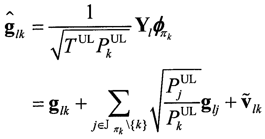
수학식 16 및 수학식 18에 따라서, 단말 k와 기지국 l 의 채널 정보 중 하나의 채널 추정 벡터를 프로젝션한 결과는 수학식 19와 같다.According to Equation (16) and Equation (18), the result of projecting one channel estimation vector among the channel information of the terminal k and the
[수학식 19] & Quot; (19 ) & quot ;

![]()
![]()
한편, Massive MIMO에서 M이 충분히 큰 경우, 수학식 19의 ![]()
![]()
[수학식 20] & Quot; (20 ) & quot ;

수학식 20에 따르면, 프로젝션된 채널 추정 벡터는 단말 i와 단말 k의 상향링크 송신 전력 및 롱텀 페이딩 성분에 의하여 표현된다. 예컨대, 숏텀 페이딩 성분이 제거된 것으로 이해될 수 있다.According to Equation (20), the projected channel estimation vector is expressed by the uplink transmission power and the long-term fading component of the terminal i and the terminal k. For example, it can be understood that the short-fading component is removed.
또한, 수학식 20에 따를 때, 프로젝션된 하나의 채널 추정 벡터는 K개의 실수값들로 구성되며, 

예를 들어, 프로젝션 방식의 다른 일 실시 예로 제로 포싱 필터(zero-forcing filter)가 프로젝션 필터로 사용될 수 있다. 제로 포싱 필터 가 사용되는 경우의 기지국 l의 프로젝션 필터는 수학식 21과 같다.For example, in another embodiment of the projection system, a zero-forcing filter can be used as a projection filter. The projection filter of the
[수학식 21] & Quot; (21 ) & quot ;

Massive MIMO에서 M이 충분히 큰 경우, 수학식 16 및 수학식 21에 기초하여 단말 k와 기지국 l 의 채널 정보(또는 채널 행렬) 중 하나의 채널 추정 벡터를 프로젝션한 결과는 수학식 22와 같다.If M in Massive MIMO is sufficiently large, the result of projecting one channel estimation vector among channel information (or channel matrix) of terminal k and
[수학식 22] & Quot; (22 ) & quot ;

수학식 22에 따르면, 프로젝션 된 채널 추정 벡터의 값들은 총 K개로서, 

이상의 프로젝션 필터들은 본 발명에 적용 가능한 프로젝션 방식들의 예시이므로, 다른 프로젝션 필터들이 사용될 수 있다.Since the above-mentioned projection filters are examples of projection methods applicable to the present invention, other projection filters can be used.
설명된 바와 같이, 프로젝션 된 채널 추정 벡터는 총 K개의 실수 값들로 구성되므로, 프로젝션 되지 않은 채널 추정 벡터 M(M>K)개의 복소수 값들에 비하여 데이터 크기가 감소한다.As explained, since the projected channel estimation vector is composed of a total of K real values, the data size decreases as compared to the complex values of the non-projected channel estimation vector M (M > K).
특히, 단말들 마다 서로 다른 RS 인덱스가 할당되는 경우 RS들이 서로 직교하므로, 프로젝션된 채널 정보(또는 채널 행렬)은 대각 행렬로 구성될 수 있다. 따라서, 프로젝션된 채널 정보는 K개의 0이 아닌 엘리먼트 만으로 표현될 수 있다. 따라서, 기지국은 KM 개의 복소 엘리먼트들을 네트워크에 피드백하는 대신에 K개의 실수 엘리먼트들을 네트워크에 피드백 할 수 있다.In particular, when different RS indices are assigned to terminals, RSs are orthogonal to each other, so that the projected channel information (or channel matrix) can be composed of a diagonal matrix. Thus, the projected channel information can be represented by only K non-zero elements. Thus, the base station may feed back K real elements to the network instead of feeding back the KM complex elements to the network.
기지국(BS), 네트워크 엔터티(NE) 또는 단말(UE)의 동작 및 구조Operation and structure of base station (BS), network entity (NE) or terminal (UE)
이하 기지국, 네트워크 엔터티 및 단말의 동작 및 구조를 설명하는데 있어서, 상술된 설명과 중복하는 내용은 설명을 생략한다.In the following description of the operation and structure of the base station, the network entity, and the terminal, descriptions overlapping with the above description are omitted.
도 7은 본 발명의 일 실시예에 따라 채널 정보를 송신 또는 수신하는 방법의 흐름을 도시한 도면이다. 도 7은 다수의 단말들 및 다수의 기지국들과 하나의 네트워크 엔터티를 포함한다. 다만, 이는 설명의 편의를 위함이며 단말, 기지국, 네트워크 엔터티의 개수는 단수 또는 복수로 변경될 수 있다.7 is a flowchart illustrating a method of transmitting or receiving channel information according to an embodiment of the present invention. 7 includes a plurality of terminals and a plurality of base stations and one network entity. However, this is for convenience of description, and the number of terminals, base stations, and network entities may be changed to one or more.
단말들은 하향링크에서 수신된 신호의 평균 파워를 측정하고(705), 측정된 평균 파워를 기지국들에 피드백 한다(710). 예컨대, 기지국들은 단말들에 하향링크 RS들을 전송할 수 있으며, 단말들은 기지국들로부터 수신된 하향링크 RS들의 RSRP(Reference Signal Received Strength)를 측정할 수 있다. 단말들은 측정된 RSRP를 기지국에 피드백 할 수 있다. 이 경우, 각 기지국들은 단말들로부터 수신한 평균 파워에 기초하여 하향링크 채널을 추정할 수 있다. 한편, TDD 시스템의 경우, 기지국은 하향링크 채널 추정에 기초하여 상향링크 채널을 추정할 수 있다. 한편, 기지국의 상향링크 채널 추정을 위하여 단말들은 상향링크 RS들을 기지국들에 전송할 수 있다(715).The UEs measure the average power of the signal received in the downlink (705), and feed back the measured average power to the base stations (710). For example, BSs can transmit downlink RSs to UEs, and UEs can measure RSRP (Reference Signal Received Received Strength) of downlink RSs received from BSs. The terminals can feed back the measured RSRP to the base station. In this case, the BSs can estimate the downlink channel based on the average power received from the UEs. Meanwhile, in the case of the TDD system, the base station can estimate the uplink channel based on the downlink channel estimation. Meanwhile, in order to estimate the uplink channel of the base station, the terminals can transmit the uplink RSs to the base stations (715).
기지국들은 상향링크 RS에 기초하여 상향링크 채널을 추정한다(720). 단말이 K개이고, 하나의 기지국에 M개의 안테나가 있다면, 각 기지국은 KM개의 채널들을 추정한다. 만약, 단말의 안테나 개수가 N이라면, 각 기지국은 NKM개의 채널들을 추정한다.The BS estimates an uplink channel based on the uplink RS (720). If there are K terminals and there are M antennas in one base station, each base station estimates KM channels. If the number of antennas of the UE is N, each base station estimates NKM channels.
한편, TDD 시스템의 경우, 기지국은 상향링크 채널 추정에 기초하여 하향링크 채널을 추정할 수도 있다.Meanwhile, in the case of the TDD system, the base station may estimate the downlink channel based on the uplink channel estimation.
705 내지 720은 기지국들에서 상향링크 또는 하향링크의 채널을 추정하는 다양한 방법들을 예시한 것이다. 예컨대, 715, 720만으로 FDD 시스템의 상향링크 채널 추정과 TDD 시스템의 상/하향링크 채널 추정이 가능하다. 따라서, 동일한 의미에서 705, 710, 720만으로 채널 추정이 수행될 수도 있다.705 through 720 illustrate various methods of estimating uplink or downlink channels in the base stations. For example, it is possible to perform the uplink channel estimation of the FDD system and the uplink / downlink channel estimation of the TDD system with only 715 and 720. Therefore, channel estimation may be performed with 705, 710, and 720 only in the same sense.
기지국들은 추정된 채널 정보 중 적어도 일부를 프로젝션 한다(725). 프로젝션을 위하여 상술된 프로젝션 기법이 사용될 수 있다. 기지국들은 전체의 채널 정보를 프로젝션할 수 있으나, 채널 정보 중 일부의 채널 정보만을 프로젝션할 수도 있다. 예컨대, 채널 정보 중 일부 안테나에 대응하는 채널 추정값들 또는 채널 추정 벡터를 선택하여 프로젝션하거나, 일부 단말에 대응하는 채널 추정값들만 선택하여 프로젝션 할 수도 있다.The base stations project at least a portion of the estimated channel information (725). The projection technique described above may be used for projection. The base stations may project the entire channel information, but may only project some channel information of the channel information. For example, channel estimation values or channel estimation vectors corresponding to some antennas in the channel information may be selected and projected, or only channel estimation values corresponding to some terminals may be selected and projected.
(7-i) 프로젝션된 채널 정보의 전송(7-i) transmission of the projected channel information
기지국들은 적어도 일부가 프로젝션된 채널 정보를 포함하는 피드백 정보를 네트워크 엔터티에 전송한다(730). 피드백 정보는, 프로젝션되지 않은 나머지 일부의 채널 정보, 프로젝션 방식에 대한 정보 및 단말의 식별 정보(또는 인덱스)를 포함할 수 있다.The base stations transmit feedback information including at least a portion of the projected channel information to the network entity (730). The feedback information may include channel information of the remaining unprojected channel, information on the projection method, and identification information (or index) of the terminal.
예를 들어, 전체 채널 정보가 프로젝션 되는 경우 기지국 l이 네트워크 엔터티로 전송하는 프로젝션 된 채널 정보는 수학식 23과 같이 표현될 수 있다.For example, when full channel information is projected, the projected channel information transmitted by the base station l to the network entity may be expressed as Equation (23).
[수학식 23] & Quot; (23 ) & quot ;
![]()
![]()
여기서 ![]()

![]()
참고로, 기지국 l이 추정한 채널 정보를 프로젝션하지 않고 네트워크 엔터티로 전송하는 경우 수학식 24와 같이 표현 될 수 있다.For reference, when the channel information estimated by the
[수학식 24] & Quot; (24 ) & quot ;
![]()
![]()
여기서 채널 정보는 총 MK 개의 복소수 값이다. 따라서 프로젝션된 채널정보는 추정한 채널 정보보다 적을 수 있다.Where the channel information is a total of MK complex values. Thus, the projected channel information may be less than the estimated channel information.
기지국 l은 네트워크 엔터티로 프로젝션된 채널 정보와 프로젝션되지 않은 채널 정보를 함께 전송할 수 있다. 이 경우, 전송되는 채널 정보는 수학식 25와 같이 표현될 수 있다.The
[수학식 25] & Quot; (25 ) & quot ;

여기서 K(1) 과 K(2)는 K의 부분집합일 수 있다.Where K (1) and K (2) may be a subset of K.
(7-ii) 제1 프리코딩 행렬의 결정(7-ii) Determination of the first precoding matrix
도 7로 돌아가서, 기지국들은 제1 프리코딩 행렬을 결정한다(735). 예컨대, 각각의 단말들에 대한 빔포밍을 위하여 기지국은 추정된 채널 정보에 기초하여 제1 프리코딩 행렬을 결정할 수 있다. 다만, 제1 프리코딩 행렬은 각 기지국이 Local하게 결정하는 것이므로, 다른 기지국과 단말의 채널 상태는 고려되지 않은 상태에서 결정된다. 즉, 제1 프리코딩 행렬은 다른 기지국과의 CoMP 송수신을 위한 것이 아니라, Local하게 결정한 빔포밍 weight를 의미한다.Returning to FIG. 7, the base stations determine 735 a first precoding matrix. For example, the base station may determine a first precoding matrix based on the estimated channel information for beamforming for each of the terminals. However, since the first precoding matrix is determined to be local by each base station, the channel state of the other base station and the terminal is determined in a state that is not considered. That is, the first precoding matrix is not for CoMP transmission / reception with other base stations, but refers to a beamforming weight determined locally.
기지국이 결정한 제1 프리코딩 행렬로서 채널 정보를 프로젝션하는데 사용한 프로젝션 행렬이 사용 될 수 있다. 예를 들어, 정합필터 (matched filter)가 사용되는 경우, 기지국 l에서 결정한 제1 프리코딩 행렬을 ![]()
![]()
[수학식 26] & Quot; (26 ) & quot ;

제로포싱필터 (zero-forcing filter)가 사용되는 경우, 기지국 l에서 결정한 제1 프리코딩 행렬을 ![]()
![]()
[수학식 27] & Quot; (27 ) & quot ;

정합필터와 제로포싱필터는 이외의 다른 프리코딩 방식들이 사용될 수 있다.Other precoding schemes may be used for the matched filter and the zero-forcing filter.
(7-iii) 제2 프리코딩 행렬의 결정(7-iii) Determination of the second precoding matrix
네트워크 엔터티는 기지국들로부터 수신한 피드백 정보에 기초하여, 제2 프리코딩 행렬 및 전송전력을 결정한다(740). 제2 프리코딩 행렬은 다수의 기지국들의 CoMP 송수신을 위한 것으로서, 다수의 기지국들에 의한 피드백 정보에 기초하여 결정된다.The network entity determines a second precoding matrix and transmit power based on the feedback information received from the base stations (740). The second precoding matrix is for CoMP transmission / reception of a plurality of base stations, and is determined based on feedback information by a plurality of base stations.
예컨대, 네트워크 엔터티는 제2 프리코딩 행렬을 ![]()
![]()
[수학식 28] & Quot; (28 ) & quot ;
![]()
![]()
수학식 28에서 ![]()
![]()
![]()
![]()
![]()
![]()
네트워크 엔터티는 다양한 방식에 따라서 제2 프리코딩 행렬을 결정할 수 있다. 일 실시 예로, 정합필터 (matched filter)에 기반한 제2 프리코딩 행렬은 수학식 29와 같다. 다른 일 실시 예로, 제로포싱필터에 기반한 제2 프리코딩 행렬은 수학식 30과 같다.The network entity may determine the second precoding matrix according to various manners. In one embodiment, a second precoding matrix based on a matched filter is given by: < EMI ID = 29.0 > In another embodiment, the second precoding matrix based on a zero forcing filter is as shown in equation (30).
[수학식 29] & Quot; (29 ) & quot ;
![]()
![]()
[수학식 30] & Quot; (30 ) & quot ;
![]()
![]()
한편, 네트워크 엔터티가 기지국에서 수신한 채널 정보가 수학식 24와 같이 프로젝션 되지 않은 채널 정보일 때, 하향링크 송수신은 수학식 31과 같이 표현될 수 있다. 이 경우, 정합 필터에 기반한 제2 프리코딩 행렬과 제로포싱필터에 기반한 제2 프리코딩 행렬은 각각 수학식 32 및 수학식 33과 같이 결정될 수 있다.Meanwhile, when the channel information received by the network entity from the base station is channel information that is not projected as in Equation 24, the downlink transmission and reception can be expressed as Equation (31). In this case, the second precoding matrix based on the matched filter and the second precoding matrix based on the zero-forcing filter can be determined as shown in Equation 32 and Equation 33, respectively.
[수학식 31] & Quot; (31 ) & quot ;
![]()
![]()
[수학식 32] [Equation 32]
![]()
![]()
[수학식 33] & Quot; (33 ) & quot ;
![]()
![]()
한편, 네트워크 엔터티가 기지국에서 수신한 채널 정보가 수학식 25와 같이 일부의 채널 정보만 프로젝션되고, 나머지 일부는 프로젝션되지 않은 경우, 각각에 대하여 수학식 28과 수학식 31을 조합하여 전체 채널에 대한 송수신 관계식이 획득될 수 있다. 이에 대하여 effective 채널 행렬을 이용하여 다양한 방식으로 제2 프리코딩 행렬을 결정할 수 있다.On the other hand, when the channel entity received by the network entity at the base station is projected with only a part of channel information as shown in Equation 25 and the remaining part is not projected, Equation (28) and Equation (31) A transmission / reception relationship can be obtained. In contrast, the second precoding matrix can be determined in various manners using an effective channel matrix.
도 7로 돌아가서, 네트워크 엔터티는 결정된 제2 프리코딩 행렬 및 전송 전력의 정보 중 적어도 하나를 각 기지국들로 전송한다(745).Returning to FIG. 7, the network entity transmits at least one of the determined second precoding matrix and transmit power information to each base station (745).
예를 들어, 중앙처리장치가 기지국 l에게 전달하는 제2 프리코딩 행렬의 정보는 수학식 34와 같이 표현 할 수 있다.For example, the information of the second precoding matrix transmitted from the central processing unit to the
[수학식 34] & Quot; (34 ) & quot ;
![]()
![]()
이어서, 각 기지국들은 수신된 제2 프리코딩 행렬의 정보 및 전송 전력의 정보를 통해서 단말들과 상향링크 또는 하향링크 신호를 송수신한다(750).Then, each base station transmits and receives uplink or downlink signals to / from the terminals through the information of the received second precoding matrix and information of the transmit power (750).
예컨대, 기지국 l은 제2 프리코딩 행렬 ![]()
![]()
![]()
![]()
![]()
![]()
[수학식 35] & Quot; (35 ) & quot ;
![]()
![]()
수학식 35에서 ![]()
![]()
도 8은 본 발명의 일 실시예에 따라 기지국이 채널 정보를 피드백하는 방법의 흐름을 도시한 도면이다. 전술한 실시예들과 중복되는 내용은 그 설명을 생략한다.8 is a flowchart illustrating a method of feedback of channel information by a base station according to an embodiment of the present invention. The description overlapping with the above embodiments is omitted.
기지국은 다수의 안테나들을 통해 수신된 하나 또는 둘 이상의 단말들로부터의 신호들에 기초하여 각각의 안테나들과 각각의 단말들 간의 다중의 채널들을 추정(estimation)한다(805). 이 때, 기지국이 수신한 신호는 RS 일 수 있다.The base station estimates multiple channels (805) between each of the antennas and each of the terminals based on signals from one or more terminals received via multiple antennas. At this time, the signal received by the base station may be RS.
기지국은 단말 들 중에서 적어도 하나의 단말을 선택한다(810). 기지국은 선택된 단말에 대응하는 채널 추정값을 제1 공간에서 제2 공간으로 프로젝션하기 위하여, 적어도 하나의 단말을 선택할 수 있다. 제1 공간은 복소 공간에 대응하고, 제2 공간은 실수 공간에 대응할 수 있다.The base station selects at least one terminal among the terminals (810). The base station may select at least one terminal to project the channel estimate corresponding to the selected terminal from the first space to the second space. The first space may correspond to the complex space, and the second space may correspond to the real space.
기지국은 단말을 선택하기 위하여 단말들로부터 수신된 신호의 평균 수신 전력 또는 패널 추정 오차를 고려할 수 있다.The BS may consider the average received power or the panel estimation error of the signal received from the MSs to select the MS.
(8-i) 평균 수신 전력에 기초한 단말의 선택(8-i) Selection of terminal based on average received power
일 실시예에 따르면, 기지국은 단말들 중에서 신호들의 평균 수신 전력이 제1 임계치 이하인 단말을 선택할 수 있다.According to one embodiment, the base station may select a terminal among the terminals whose average received power is below a first threshold.
기지국은 단말의 평균 수신 전력을 측정하고, 제1 임계치 이하의 평균 수신 전력을 전송한 단말을 선택할 수 있다. 즉, 평균 수신 전력이 제1 임계치 이하인 단말에 대응하는 채널 추정값들을 프로젝션하고, 평균 수신 전력이 제1 임계치를 초과하는 단말에 대응하는 채널 추정값들은 프로젝션 하지 않고 네트워크 엔터티에 전송할 수 있다. 이는 수학식 36과 같이 표현될 수 있다.The BS may measure the average received power of the MS and may select the MS that has transmitted the average received power below the first threshold. That is, the channel estimation values corresponding to the terminals whose average reception power is equal to or less than the first threshold value can be projected, and the channel estimation values corresponding to the terminals whose average reception power exceeds the first threshold value can be transmitted to the network entity without projection. This can be expressed as Equation (36).
[수학식 36] & Quot; (36 ) & quot ;
여기서 ![]()
![]()
(8-ii) 채널 추정 오차에 기초한 단말의 선택(8-ii) selection of a terminal based on channel estimation error
기지국은 추정된 채널 정보에 대한 오차를 이용하여, 단말을 선택할 수 있다. 일 실시예에 따르면, 기지국은 단말들 중에서 채널 추정값에 대한 채널 추정 오차가 제2 임계치 이상인 단말을 선택할 수 있다.The base station can select the terminal using the error of the estimated channel information. According to one embodiment, the base station can select a terminal among the terminals whose channel estimation error is equal to or greater than the second threshold.
채널 추정 오차는 수학식 37과 같이 표현될 수 있다.The channel estimation error can be expressed by Equation (37).
[수학식 37] & Quot; (37 ) & quot ;
수학식 37에서 
[수학식 38] & Quot; (38 ) & quot ;

여기서 ![]()
![]()
도 8로 돌아가서, 기지국은 프로젝션 방식을 결정한다(815). 프로젝션 방식은 예컨대, 정규화된 정합 필터 기반의 방식 또는 제로 포싱 필터 기반의 방식일 수 있고 이에 한정되지 않는다.Returning to Fig. 8, the base station determines a projection scheme (815). The projection scheme may be, for example, a normalized matched filter-based scheme or a zero-forcing filter-based scheme, but is not limited thereto.
기지국은 결정된 프로젝션 방식에 따라서 선택된 단말에 대응하는 채널 추정값들을 프로젝션 한다(820).The base station projects the channel estimation values corresponding to the selected terminal according to the determined projection method (820).
예컨대, 선택된 단말의 개수가 K1이라고 하면, 기지국은 K×M개의 복소수 채널 추정값들 중에서 선택된 K1×M개의 복소수 채널 추정값들을 선택한다. 기지국은 선택된 K1×M개의 복소수 채널 추정값들로부터 K1×K1개의 실수의 채널 추정값들을 획득한다.For example, if the number of selected terminals is K1, the base station selects K1 × M complex channel estimation values selected from the K × M complex channel estimation values. The base station obtains K1 x K1 real channel estimates from the selected K1 x M complex channel estimates.
기지국은 결정된 프로젝션 방식에 따라서, 정규화된 정합 필터(normalized matched filter) 또는 제로 포싱 필터(zero-forcing filter)를 이용하여 프로젝션한다. 정규화된 정합 필터를 이용한 프로젝션 결과는 수학식 20에 대응하고, 제로 포싱 필터를 이용한 프로젝션 결과는 수학식 22에 대응한다.The base station projects using a normalized matched filter or a zero-forcing filter according to the determined projection method. The projection result using the normalized matched filter corresponds to the expression (20), and the projection result using the zero-forcing filter corresponds to the expression (22).
한편, 기지국의 프로젝션은, 채널 추정값들이 포함하는 제1 페이딩 성분 및 제2 페이딩 성분 중에서 코히어런스 시간(coherence time)이 작은 페이딩 성분을 제거하는 것으로 이해될 수 있다. 즉, 채널 추정값들에 포함된 롱텀 페이딩 성분과 숏텀 페이딩 성분 중 숏텀 페이딩 성분은 프로젝션에 의해서 제거될 수 있다. 따라서, 프로젝션된 채널 추정값들의 데이터 크기는 프로젝션되기 전보다 감소한다.On the other hand, it can be understood that the projection of the base station removes a fading component having a small coherence time from the first fading component and the second fading component included in the channel estimation values. That is, the short-term fading component of the long-term fading component and the short-term fading component included in the channel estimation values can be removed by projection. Thus, the data size of the projected channel estimates is less than before projection.
기지국은 프로젝션된 채널 추정값을 포함하는 피드백 정보를 네트워크 엔터티에 전송한다(825). 피드백 정보는, 다수의 프로젝션 방식들 중 적어도 일부의 채널 추정값을 프로젝션하는데 사용된 프로젝션 방식을 나타내는 프로젝션 방식 정보, 프로젝션된 적어도 일부의 채널 추정값에 대응하는 단말을 나타내는 단말 정보 및 채널 추정값들 중 프로젝션되지 않은 나머지 일부의 채널 추정값 중 적어도 하나를 더 포함할 수 있다.The base station transmits feedback information including the projected channel estimate to the network entity (825). The feedback information includes projection scheme information indicating a projection scheme used to project at least some of the channel estimation values of the plurality of projection schemes, terminal information indicating a terminal corresponding to at least some of the projected channel estimates, And may further include at least one of the remaining channel estimation values.
도 10은 본 발명의 일 실시예에 따른 피드백 정보의 구조를 도시한다. 도 10을 참조하면, 피드백 정보는 N1 비트의 프로젝션 방식 인덱스, N2 비트의 단말 정보, N3 비트의 프로젝션된 채널 정보, N4 비트의 추정된 채널 정보를 포함한다. N2 비트의 단말 정보는 어떤 단말의 채널 정보가 프로젝션되었는지, 어떤 단말의 채널 정보가 프로젝션되지 않았는지를 구별하기 위한 정보이다.10 shows a structure of feedback information according to an embodiment of the present invention. Referring to FIG. 10, the feedback information includes N1-bit projection-type index, N2-bit terminal information, N3-bit projected channel information, and N4-bit estimated channel information. The terminal information of N2 bits is information for distinguishing which terminal's channel information is projected and which terminal's channel information is not projected.
기지국은 채널 추정값을 프로젝션하는데 사용된 프로젝션 행렬로부터 제1 프리코딩 행렬의 정보를 결정한다(830).The base station determines information of the first precoding matrix from the projection matrix used to project the channel estimate (830).
기지국은 네트워크 엔터티로부터 제2 프리코딩 행렬의 정보 및 전송 전력의 정보 중 적어도 하나를 수신한다(835). 제2 프리코딩 행렬의 정보는, 기지국이 전송한 프로젝션된 적어도 일부의 채널 추정값들 및 단말들에 대하여 CoMP(Coordinated Multi-point) 동작을 수행하는 다른 기지국이 네트워크 엔터티에 전송한 채널 추정값들에 기초하여 결정된 것임은 이미 설명한바 있다.The base station receives (835) at least one of information of the second precoding matrix and information of transmit power from the network entity. The information of the second precoding matrix may be based on at least some of the projected channel estimates transmitted by the base station and channel estimates sent to the network entity by other base stations performing Coordinated Multi-Point (CoMP) It has already been explained that it has been decided by.
기지국은 제1 프리코딩 행렬의 정보 및 제2 프리코딩 행렬의 정보에 기초하여 단말들에 전송할 하향링크 신호들을 프리코딩한다(840).The base station precodes the downlink signals to be transmitted to the UEs based on the information of the first precoding matrix and the information of the second precoding matrix (840).
기지국은 네트워크 엔터티로부터 수신된 단말들에 대한 하향링크 송신 전력에 대한 정보에 기초하여, 프리코딩된 하향링크 신호들을 전송한다(845).The base station transmits 845 precoded downlink signals based on information on downlink transmission power for terminals received from the network entity.
도 9는 본 발명의 일 실시예에 따라 네트워크 엔터티가 기지국으로부터 채널 정보를 수신하는 방법의 흐름을 도시한 도면이다. 전술한 설명과 중복되는 내용은 설명을 생략한다.9 is a flowchart illustrating a method for a network entity to receive channel information from a base station according to an embodiment of the present invention. The description overlapping with the above description is omitted.
네트워크 엔터티는, 하나 또는 둘 이상의 기지국들로부터 각 기지국들에 의한 채널 추정값들을 포함하는 피드백 정보를 수신한다(905). 예컨대, 네트워크 엔터티는, 제1 기지국으로부터 제1 기지국의 안테나들과 단말들간의 제1 채널 추정값들을 포함하는 제1 피드백 정보를 수신한다. 네트워크 엔터티는, 제2 기지국으로부터 제2 기지국의 안테나들과 단말들간의 제2 채널 추정값들을 포함하는 제2 피드백 정보를 수신한다. 이 때, 제1 채널 추정값들 및 제2 채널 추정값들 중 적어도 일부는 제1 공간에서 제2 공간으로 프로젝션된 것이다.The network entity receives feedback information including channel estimates by each base station from one or more base stations (905). For example, the network entity receives first feedback information including first channel estimates between first base station antennas and terminals from a first base station. The network entity receives second feedback information including second channel estimates between the antennas of the second base station and the terminals from the second base station. At this time, at least some of the first channel estimation values and the second channel estimation values are projected from the first space to the second space.
네트워크 엔터티는 채널 추정값들이 프로젝션된 방식을 판단한다(910). 네트워크 엔터티는 피드백 정보에 포함된 프로젝션 방식에 대한 정보를 이용할 수 있다.The network entity determines 910 how the channel estimates are projected. The network entity may use the information on the projection method included in the feedback information.
네트워크 엔터티는 프로젝션 방식에 따라서 제2 프리코딩 행렬을 결정한다(915). 제2 프리코딩 행렬을 결정하기 위하여, 피드백 정보가 이용될 수 있다. 네트워크 엔터티는 피드백 정보에 기초하여 송신전력을 결정한다(920). 네트워크 엔터티는 제2 프리코딩 행렬의 정보 및 송신 전력의 정보를 기지국들에 전송한다(925).The network entity determines a second precoding matrix according to the projection scheme (915). In order to determine the second precoding matrix, feedback information may be used. The network entity determines the transmit power based on the feedback information (920). The network entity transmits information of the second precoding matrix and information of the transmission power to the base stations (925).
도 11는 본 발명의 일 실시예에 따른 단말을 도시한 도면이다. 도 11에 도시된 단말은 전술한 실시예들에서의 단말의 동작을 수행할 수 있다.11 is a diagram illustrating a terminal according to an embodiment of the present invention. The terminal shown in FIG. 11 can perform the operation of the terminal in the above-described embodiments.
도 11을 참조하면, 단말은 무선 인터페이스(1101), 프로세서(1104) 및 메모리(1103)을 포함한다.11, the terminal includes a
무선 인터페이스(1101)는 RF 신호를 송수신하기 위한 송수신기를 포함할 수 있다.The
메모리(1103)는 평균 신호 파워 및 RS를 저장할 수 있다. 메모리(1103)는 프로세서(1104)가 측정한 인접한 셀들로부터 기지국으로 오는 신호 파워를 저장할 수 있다. 저장된 평균 신호 파워는 기지국의 요청에 따라 무선 채널을 통하여 기지국에 피드백 될 수 있다. 메모리(1103)는 네트워크에서 사용되는 RS 시퀀스들을 저장할 수 있다. 저장된 RS 시퀀스들은 상향링크 채널 추정을 위하여 사용될 수 있다.
프로세서(1104)는 평균 신호 파워를 측정할 수 있다. 프로세서(1104)는 서빙 기지국에 인접한 셀의 다른 단말 또는 서빙 셀의 다른 단말로부터 평균 신호 파워를 누적하여 측정할 수 있다. 프로세서(1104)는 측정된 평균 신호 파워를 메모리(1103)에 저장한다. 프로세서(1104)는 상향링크 채널의 추정을 위한 RS를 기지국으로 전송한다. 프로세서(1104)는 메모리(1103)에 저장된 RS 시퀀스를 이용할 수 있다. 프로세서(1104)는 단말과 기지국간의 사용자 데이터의 송수신을 제어한다.The
도 12는 본 발명의 일 실시예에 따른 기지국을 도시한 도면이다. 도 12에 도시된 기지국은 전술한 실시예들에서의 기지국의 동작을 수행할 수 있다.12 is a diagram illustrating a base station according to an embodiment of the present invention. The base station shown in Fig. 12 can perform the operation of the base station in the above-described embodiments.
기지국은 MU-MIMO를 위한 다수의 안테나들, 무선 인터페이스(1201), 백홀 인터페이스(1202), 메모리(1203) 및 프로세서(1204)를 포함한다.The base station includes a plurality of antennas for MU-MIMO, a
무선 인터페이스(1201)는 다수의 안테나들을 통해 단말들과 신호들을 송수신한다.The
프로세서(1204)는 단말들로부터 수신된 신호들에 기초하여 각각의 안테나들과 각각의 단말들 간의 다중의 채널들을 추정한다. 프로세서(1204)는 다중의 채널들의 채널 추정값들 중 적어도 일부를 제1 공간에서 제2 공간으로 프로젝션한다.The
백홀 인터페이스(1202)는, 프로세서(1204)의 제어에 따라서, 제2 공간으로 프로젝션된 적어도 일부의 채널 추정값들을 포함하는 피드백 정보를 네트워크 엔터티에 전송한다.The
메모리(1203)는 프로세서(1204)에서 측정하거나 단말로부터 피드백 받은 단말의 수신 신호 파워를 저장할 수 있다. 메모리(1203)는 네트워크에서 사용하는 RS 시퀀스들을 저장할 수 있다. 저장된 RS 시퀀스들은 상향링크 채널 추정을 위하여 사용된다. 메모리(1203)는 프로세서(1204)에서 추정한 채널 정보를 저장할 수 있다. 저장된 채널 정보는 백홀 인터페이스(1203)를 통해 기지국에 전송되거나, 제1 프리코딩 행렬을 결정하기 위해 사용할 수 있다. 메모리(1203)는 피드백 정보를 저장하거나, 네트워크 엔터티로부터 수신한 정보를 저장할 수 있다. 메모리(1203)는 프로세서(1204)가 결정한 제1 프리코딩 행렬을 저장할 수 있다.The
프로세서(1204)는 각 단말이 송신하는 신호의 파워를 측정 할 수 있다. 프로세서(1204)는 측정된 평균 수신 파워를 메모리(1203)에 저장한다. 프로세서(1204)는 단말로부터의 RS를 통해 채널 정보를 추정한다. 프로세서(1204)는 추정한 채널 정보를 메모리(1203)에 저장한다. 프로세서(1204)는 추정된 채널 정보를 프로젝션 할 수 있다. 프로세서(1204)는 제1 프리코딩 행렬을 결정할 수 있다. 프로세서(1204)는 피드백 정보를 네트워크 엔터티에 전송하거나, 네트워크 엔터티로부터 정보를 수신할 수 있다. 프로세서(1204)는 단말과 사용자 데이터를 송신하고 수신하는 역할을 수행 할 수 있다.The
도 13은 본 발명의 일 실시예에 따른 네트워크 엔터티를 도시한 도면이다. 도 13에 도시된 네트워크 엔터티는 전술한 실시예들에서의 네트워크 엔터티의 동작을 수행할 수 있다.13 is a diagram illustrating a network entity according to an embodiment of the present invention. The network entity shown in FIG. 13 may perform the operation of the network entity in the above-described embodiments.
네트워크 엔터티는 백홀 인터페이스(1302), 메모리(1303) 및 프로세서(1304)를 포함한다.The network entity includes a
백홀 인터페이스(1302)는 프로세서(1304)의 제어에 따라서, 제1 기지국으로부터 제1 기지국의 안테나들과 단말들간의 제1 채널 추정값들을 포함하는 제1 피드백 정보를 수신한다. 백홀 인터페이스(1302)는 제2 기지국으로부터 제2 기지국의 안테나들과 단말들간의 제2 채널 추정값들을 포함하는 제2 피드백 정보를 수신한다. 제1 채널 추정값들 및 제2 채널 추정값들 중 적어도 일부는 제1 공간에서 제2 공간으로 프로젝션된 것 일 수 있다.The
메모리(1303)는 기지국으로부터 수신한 피드백 정보를 저장 할 수 있다. 메모리(1303)는 프로세서(1304)가 결정한 제2 프리코딩 행렬을 저장할 수 있다. 메모리(1303)는 프로세서(1304)가 결정한 송신 전력의 정보를 저장할 수 있다.The
프로세서(1304)는 기지국으로부터 피드백 정보를 수신하고, 기지국에 정보를 전송하도록 백홀 인터페이스(1302)를 제어할 수 있다. 프로세서(1304)는 제2 프리코딩 행렬을 결정하고, 메모리(1303)에 저장할 수 있다. 프로세서(1304)는 메모리(1303)에 저장된 정보를 이용하여 송신 전력의 정보를 결정할 수 있다.The
도 14는 본 발명의 다른 일 실시예에 따른 단말과 기지국을 도시한 도면이다. 도 14의 단말과 기지국은 각각 전술한 실시예들의 단말과 기지국의 동작을 수행할 수 있다.FIG. 14 is a diagram illustrating a terminal and a base station according to another embodiment of the present invention. The terminal and the base station in FIG. 14 can perform operations of the terminal and the base station in the above-described embodiments, respectively.
기지국(1410)은, 수신모듈(1411), 전송모듈(1412), 프로세서(1413), 메모리(1414) 및 복수개의 안테나(1415)를 포함할 수 있다. 복수개의 안테나(1415)는 MIMO 송수신을 지원하는 기지국을 의미한다. 수신모듈(1411)은 단말로부터의 상향링크 상의 각종 신호, 데이터 및 정보를 수신할 수 있다. 전송모듈(1412)은 단말로의 하향링크 상의 각종 신호, 데이터 및 정보를 전송할 수 있다. 프로세서(1413)는 기지국(1410) 전반의 동작을 제어할 수 있다.The
기지국(1410)의 프로세서(1413)는 그 외에도 기지국(1410)가 수신한 정보, 외부로 전송할 정보 등을 연산 처리하는 기능을 수행하며, 메모리(1414)는 연산 처리된 정보 등을 소정시간 동안 저장할 수 있으며, 버퍼(미도시) 등의 구성요소로 대체될 수 있다.The
단말(1420)은, 수신모듈(1421), 전송모듈(1422), 프로세서(1423), 메모리(1424) 및 복수개의 안테나(1425)를 포함할 수 있다. 복수개의 안테나(1425)는 MIMO 송수신을 지원하는 단말을 의미한다. 수신모듈(1421)은 기지국으로부터의 하향링크 상의 각종 신호, 데이터 및 정보를 수신할 수 있다. 전송모듈(1422)은 기지국으로의 상향링크 상의 각종 신호, 데이터 및 정보를 전송할 수 있다. 프로세서(1423)는 단말(1420) 전반의 동작을 제어할 수 있다.The terminal 1420 may include a
단말(1420)의 프로세서(1423)는 그 외에도 단말(1420)가 수신한 정보, 외부로 전송할 정보 등을 연산 처리하는 기능을 수행하며, 메모리(1424)는 연산 처리된 정보 등을 소정시간 동안 저장할 수 있으며, 버퍼(미도시) 등의 구성요소로 대체될 수 있다.The
위와 같은 기지국 및 단말의 구체적인 구성은, 전술한 본 발명의 다양한 실시예에서 설명한 사항들이 독립적으로 적용되거나 또는 2 이상의 실시예가 동시에 적용되도록 구현될 수 있으며, 중복되는 내용은 명확성을 위하여 설명을 생략한다.The specific configurations of the base station and the terminal as described above may be implemented such that the elements described in the various embodiments of the present invention described above are applied independently or two or more embodiments are applied at the same time and the duplicated description is omitted for the sake of clarity .
또한, 도 14에 대한 설명에 있어서 기지국(1410)에 대한 설명은 하향링크 전송 주체 또는 상향링크 수신 주체로서의 중계기 장치에 대해서도 동일하게 적용될 수 있고, 단말(1420)에 대한 설명은 하향링크 수신 주체 또는 상향링크 전송 주체로서의 중계기 장치에 대해서도 동일하게 적용될 수 있다.14, the description of the
상술한 본 발명의 실시예들은 다양한 수단을 통해 구현될 수 있다. 예를 들어, 본 발명의 실시예들은 하드웨어, 펌웨어(firmware), 소프트웨어 또는 그것들의 결합 등에 의해 구현될 수 있다.The above-described embodiments of the present invention can be implemented by various means. For example, embodiments of the present invention may be implemented by hardware, firmware, software, or a combination thereof.
하드웨어에 의한 구현의 경우, 본 발명의 실시예들에 따른 방법은 하나 또는 그 이상의 ASICs(Application Specific Integrated Circuits), DSPs(Digital Signal Processors), DSPDs(Digital Signal Processing Devices), PLDs(Programmable Logic Devices), FPGAs(Field Programmable Gate Arrays), 프로세서, 컨트롤러, 마이크로 컨트롤러, 마이크로 프로세서 등에 의해 구현될 수 있다.In the case of hardware implementation, the method according to embodiments of the present invention may be implemented in one or more Application Specific Integrated Circuits (ASICs), Digital Signal Processors (DSPs), Digital Signal Processing Devices (DSPDs), Programmable Logic Devices (PLDs) , FPGAs (Field Programmable Gate Arrays), processors, controllers, microcontrollers, microprocessors, and the like.
펌웨어나 소프트웨어에 의한 구현의 경우, 본 발명의 실시예들에 따른 방법은 이상에서 설명된 기능 또는 동작들을 수행하는 모듈, 절차 또는 함수 등의 형태로 구현될 수 있다. 소프트웨어 코드는 메모리 유닛에 저장되어 프로세서에 의해 구동될 수 있다. 상기 메모리 유닛은 상기 프로세서 내부 또는 외부에 위치하여, 이미 공지된 다양한 수단에 의해 상기 프로세서와 데이터를 주고 받을 수 있다.In the case of an implementation by firmware or software, the method according to embodiments of the present invention may be implemented in the form of a module, a procedure or a function for performing the functions or operations described above. The software code can be stored in a memory unit and driven by the processor. The memory unit may be located inside or outside the processor, and may exchange data with the processor by various well-known means.
상술한 바와 같이 개시된 본 발명의 바람직한 실시예들에 대한 상세한 설명은 당업자가 본 발명을 구현하고 실시할 수 있도록 제공되었다. 상기에서는 본 발명의 바람직한 실시예들을 참조하여 설명하였지만, 해당 기술 분야의 숙련된 당업자는 본 발명의 영역으로부터 벗어나지 않는 범위 내에서 본 발명을 다양하게 수정 및 변경시킬 수 있음을 이해할 수 있을 것이다. 예를 들어, 당업자는 상술한 실시예들에 기재된 각 구성을 서로 조합하는 방식으로 이용할 수 있다. 따라서, 본 발명은 여기에 나타난 실시형태들에 제한되려는 것이 아니라, 여기서 개시된 원리들 및 신규한 특징들과 일치하는 최광의 범위를 부여하려는 것이다.DETAILED DESCRIPTION OF THE PREFERRED EMBODIMENTS The foregoing description of the preferred embodiments of the invention disclosed herein has been presented to enable any person skilled in the art to make and use the present invention. While the present invention has been particularly shown and described with reference to preferred embodiments thereof, it will be understood by those skilled in the art that various changes and modifications may be made therein without departing from the spirit and scope of the invention as defined by the appended claims. For example, those skilled in the art can utilize each of the configurations described in the above-described embodiments in a manner of mutually combining them. Accordingly, the present invention is not intended to be limited to the embodiments shown herein but is to be accorded the widest scope consistent with the principles and novel features disclosed herein.
본 발명은 본 발명의 정신 및 필수적 특징을 벗어나지 않는 범위에서 다른 특정한 형태로 구체화될 수 있다. 따라서, 상기의 상세한 설명은 모든 면에서 제한적으로 해석되어서는 아니 되고 예시적인 것으로 고려되어야 한다. 본 발명의 범위는 첨부된 청구항의 합리적 해석에 의해 결정되어야 하고, 본 발명의 등가적 범위 내에서의 모든 변경은 본 발명의 범위에 포함된다. 또한, 특허청구범위에서 명시적인 인용 관계가 있지 않은 청구항들을 결합하여 실시예를 구성하거나 출원 후의 보정에 의해 새로운 청구항으로 포함할 수 있다.The present invention may be embodied in other specific forms without departing from the spirit or essential characteristics thereof. Accordingly, the above description should not be construed in a limiting sense in all respects and should be considered illustrative. The scope of the present invention should be determined by rational interpretation of the appended claims, and all changes within the scope of equivalents of the present invention are included in the scope of the present invention. In addition, claims that do not have an explicit citation in the claims may be combined to form an embodiment or be included in a new claim by amendment after the filing.
Claims (17)
다수의 안테나들을 통해 수신된 단말들로부터의 신호들에 기초하여 상기 각각의 안테나들과 상기 각각의 단말들 간의 다중의 채널들을 추정(estimation)하는 단계;
상기 다중의 채널들의 채널 추정값들 중 적어도 일부를 제1 공간에서 제2 공간으로 프로젝션하는 단계; 및
상기 제2 공간으로 프로젝션된 상기 적어도 일부의 채널 추정값들을 포함하는 피드백 정보를 상기 네트워크 엔터티에 전송하는 단계를 포함하는, 방법.A method for a base station supporting MU-MIMO feedback channel information of multiple users to a network entity,
Estimating multiple channels between the respective antennas and the respective terminals based on signals from the terminals received through the multiple antennas;
Projecting at least some of the channel estimates of the multiple channels from a first space to a second space; And
And transmitting feedback information to the network entity including the at least some of the channel estimates projected into the second space.
상기 단말들 중 적어도 하나의 단말을 선택하는 단계를 더 포함하고,
상기 프로젝션하는 단계는, 상기 선택된 적어도 하나의 단말에 대응하는 채널 추정값을 상기 제1 공간에서 상기 제2 공간으로 프로젝션하는, 방법.The method according to claim 1,
Further comprising selecting at least one terminal among the terminals,
Wherein the projecting step projects a channel estimate corresponding to the selected at least one terminal from the first space to the second space.
상기 단말들 중에서 상기 신호들의 평균 수신 전력이 제1 임계치 이하인 단말을 선택하거나, 또는 채널 추정 오차가 제2 임계치 이상인 단말을 선택하는, 방법.3. The method of claim 2,
Selecting a terminal having an average received power of the signals less than or equal to a first threshold or selecting a terminal having a channel estimation error equal to or greater than a second threshold.
K×M개의 복소 채널 추정값들 중에서 선택된 K1×M개의 복소 채널 추정값들로부터 K1×K1개의 실수의 채널 추정값들을 획득하고,
상기 K는 상기 신호들을 전송한 단말들의 개수이고, 상기 K1은 상기 선택된 적어도 하나의 단말의 개수이고, 상기 M은 상기 안테나들의 개수인, 방법.3. The method of claim 2,
Obtaining K1 x K1 real channel estimation values from the K1xM complex channel estimation values selected from the KxM complex channel estimation values,
Wherein K is the number of terminals transmitting the signals, K1 is the number of the selected at least one terminal, and M is the number of antennas.
상기 제1 공간에서 상기 적어도 일부의 채널 추정값들이 포함하는 상기 다중 채널들에 대한 제1 페이딩 성분 및 제2 페이딩 성분 중에서 코히어런스 시간(coherence time)이 작은 페이딩 성분을 제거하는, 방법.2. The method of claim 1,
And removing a fading component having a small coherence time from the first fading component and the second fading component for the multiple channels included in the at least some channel estimation values in the first space.
상기 제1 공간은 복소 공간에 대응하고, 상기 제2 공간은 실수 공간에 대응하고,
상기 제2 공간으로 프로젝션된 상기 적어도 일부의 채널 추정값들의 데이터 크기는 상기 프로젝션되기 전보다 감소하는, 방법.The method according to claim 1,
Wherein the first space corresponds to a complex space, the second space corresponds to a real space,
Wherein the data size of the at least some of the channel estimates projected into the second space is reduced prior to being projected.
다수의 프로젝션 방식들 중 상기 적어도 일부의 채널 추정값을 프로젝션하는데 사용된 프로젝션 방식을 나타내는 프로젝션 방식 정보;
상기 프로젝션된 상기 적어도 일부의 채널 추정값에 대응하는 단말을 나타내는 단말 정보; 및
상기 채널 추정값들 중 상기 제2 공간으로 프로젝션되지 않은 나머지 일부의 채널 추정값 중에서 적어도 하나를 포함하는, 방법.2. The method of claim 1,
Projection scheme information indicating a projection scheme used to project the at least some of the plurality of projection schemes;
Terminal information indicating a terminal corresponding to the projected at least a part of the channel estimation value; And
And at least one of the remaining channel estimates not projected to the second space among the channel estimates.
정규화된 정합 필터(normalized matched filter) 또는 제로 포싱 필터(zero-forcing filter)를 이용하여 상기 단말들 중 제1 단말에 대응하는 채널 추정값을 프로젝션하는 단계를 포함하는, 방법.2. The method of claim 1,
And projecting a channel estimate corresponding to a first one of the terminals using a normalized matched filter or a zero-forcing filter.
상기 정규화된 정합 필터를 이용한 프로젝션 결과는,

상기 제로 포싱 필터를 이용한 프로젝션 결과는,

상기 l은 상기 기지국의 인덱스, 상기 k는 상기 제1 단말의 인덱스, 상기 i는 상기 단말들 중 제2 단말의 인덱스, 상기 π k 는 상기 제1 단말로부터 수신된 신호의 인덱스, 상기
The result of projection using the normalized matched filter is:
The result of the projection using the zero forcing filter,
Wherein l is the index k is the index of the received signal, from the π k is the first terminal of the second terminal of the index, the i of the first terminal is the terminal, an index of the BS, the
상기 적어도 하나의 채널 추정값을 프로젝션하는데 사용된 프로젝션 행렬로부터 제1 프리코딩 행렬의 정보를 획득하는 단계;
상기 네트워크 엔터티로부터 제2 프리코딩 행렬의 정보를 수신하는 단계; 및
상기 제1 프리코딩 행렬의 정보 및 상기 제2 프리코딩 행렬의 정보에 기초하여 상기 단말들에 전송할 하향링크 신호들을 프리코딩하는 단계를 더 포함하는, 방법.The method according to claim 1,
Obtaining information of a first precoding matrix from a projection matrix used to project the at least one channel estimate;
Receiving information of a second precoding matrix from the network entity; And
Precoding the downlink signals to transmit to the terminals based on the information of the first precoding matrix and the information of the second precoding matrix.
상기 네트워크 엔터티로부터 수신된 상기 단말들에 대한 하향링크 송신 전력에 대한 정보에 기초하여, 상기 프리코딩된 하향링크 신호들을 전송하는 단계를 더 포함하는, 방법.11. The method of claim 10,
Further comprising transmitting the precoded downlink signals based on information on downlink transmission power for the terminals received from the network entity.
상기 기지국이 전송한 상기 프로젝션된 적어도 일부의 채널 추정값들 및 상기 단말들에 대하여 CoMP(Coordinated Multi-point) 동작을 수행하는 다른 기지국이 상기 네트워크 엔터티에 전송한 채널 추정값들에 기초하여 결정된 것인, 방법.11. The method of claim 10, wherein the information of the second precoding matrix includes:
Wherein the at least some of the projected channel estimates transmitted by the base station and the channel estimates sent to the network entity by another base station performing Coordinated Multi-Point (CoMP) Way.
상기 기지국들 중 제1 기지국으로부터 상기 제1 기지국의 안테나들과 단말들간의 제1 채널 추정값들을 포함하는 제1 피드백 정보를 수신하는 단계; 및
상기 기지국들 중 제2 기지국으로부터 상기 제2 기지국의 안테나들과 상기 단말들간의 제2 채널 추정값들을 포함하는 제2 피드백 정보를 수신하는 단계를 포함하고,
상기 제1 채널 추정값들 및 상기 제2 채널 추정값들 중 적어도 일부는 제1 공간에서 제2 공간으로 프로젝션된 것인, 방법.A method for receiving channel information of multiple users from a base station supporting a MU-MIMO by a network entity,
Receiving first feedback information including first channel estimation values between antennas of the first base station and terminals from a first one of the base stations; And
Receiving second feedback information including second channel estimates between the antennas of the second base station and the terminals from a second one of the base stations,
Wherein at least some of the first channel estimates and the second channel estimates are projected from a first space to a second space.
상기 제1 피드백 정보 및 상기 제2 피드백 정보에 기초하여, 상기 제1 기지지국 및 상기 제2 기지국 각각의 하향링크 송신 전력 및 프리코딩 행렬의 정보를 결정하는 단계를 더 포함하는, 방법.14. The method of claim 13,
Further comprising determining information of a downlink transmission power and a precoding matrix of each of the first base station and the second base station based on the first feedback information and the second feedback information.
상기 제1 및 제2 채널 추정값들 중 적어도 일부를 프로젝션하는데 사용된 프로젝션 방식에 기초하여 결정하는, 방법.15. The method of claim 14, wherein determining the precoding matrix further comprises:
Based on a projection scheme used to project at least some of the first and second channel estimate values.
MU-MIMO를 위한 다수의 안테나들;
상기 다수의 안테나들을 통해 단말들과 신호들을 송수신하는 무선 frequency) 인터페이스;
상기 단말들로부터 수신된 신호들에 기초하여 상기 각각의 안테나들과 상기 각각의 단말들 간의 다중의 채널들을 추정하고, 상기 다중의 채널들의 채널 추정값들 중 적어도 일부를 제1 공간에서 제2 공간으로 프로젝션하는 프로세서; 및
상기 프로세서의 제어에 따라서, 상기 제2 공간으로 프로젝션된 상기 적어도 일부의 채널 추정값들을 포함하는 피드백 정보를 상기 네트워크 엔터티에 전송하는 백홀(backhaul) 인터페이스를 포함하는, 기지국.A base station for feeding back channel information of multiple users to a network entity,
Multiple antennas for MU-MIMO;
A radio frequency (RF) interface for transmitting and receiving signals to and from the terminals via the plurality of antennas;
Estimating multiple channels between each of the antennas and each of the terminals based on signals received from the terminals and transmitting at least some of the channel estimates of the multiple channels from the first space to the second space A processor for projecting; And
And a backhaul interface for transferring feedback information to the network entity, the feedback information comprising the at least some of the channel estimates projected into the second space under control of the processor.
프로세서; 및
상기 프로세서의 제어에 따라서, 상기 기지국들 중 제1 기지국으로부터 상기 제1 기지국의 안테나들과 단말들간의 제1 채널 추정값들을 포함하는 제1 피드백 정보를 수신하고, 상기 기지국들 중 제2 기지국으로부터 상기 제2 기지국의 안테나들과 상기 단말들간의 제2 채널 추정값들을 포함하는 제2 피드백 정보를 수신하는 백홀(backhaul) 인터페이스를 포함하고,
상기 제1 채널 추정값들 및 상기 제2 채널 추정값들 중 적어도 일부는 제1 공간에서 제2 공간으로 프로젝션된 것인, 네트워크 엔터티.A network entity for receiving channel information of multiple users from base stations supporting MU-MIMO,
A processor; And
Receiving first feedback information including first channel estimation values between antennas of the first base station and the UEs from a first one of the base stations under control of the processor, And a backhaul interface for receiving second feedback information comprising antennas of a second base station and second channel estimates between the terminals,
Wherein at least some of the first channel estimates and the second channel estimates are projected from a first space to a second space.
Priority Applications (2)
| Application Number | Priority Date | Filing Date | Title |
|---|---|---|---|
| KR1020140080849A KR20160002078A (en) | 2014-06-30 | 2014-06-30 | Method and Apparatus of transmitting or receiving channel information of multi-user in a wireless communication system |
| US14/747,943 US9559762B2 (en) | 2014-06-30 | 2015-06-23 | Method of transceiving feedback information in wireless communication system and apparatus therefor |
Applications Claiming Priority (1)
| Application Number | Priority Date | Filing Date | Title |
|---|---|---|---|
| KR1020140080849A KR20160002078A (en) | 2014-06-30 | 2014-06-30 | Method and Apparatus of transmitting or receiving channel information of multi-user in a wireless communication system |
Publications (1)
| Publication Number | Publication Date |
|---|---|
| KR20160002078A true KR20160002078A (en) | 2016-01-07 |
Family
ID=55168793
Family Applications (1)
| Application Number | Title | Priority Date | Filing Date |
|---|---|---|---|
| KR1020140080849A Withdrawn KR20160002078A (en) | 2014-06-30 | 2014-06-30 | Method and Apparatus of transmitting or receiving channel information of multi-user in a wireless communication system |
Country Status (1)
| Country | Link |
|---|---|
| KR (1) | KR20160002078A (en) |
-
2014
- 2014-06-30 KR KR1020140080849A patent/KR20160002078A/en not_active Withdrawn
Similar Documents
| Publication | Publication Date | Title |
|---|---|---|
| US11991540B2 (en) | Method and apparatus for feeding back aggregated channel state information in cooperative multipoint communication system | |
| KR101967296B1 (en) | Method and device for transmitting/receiving downlink reference signal in wireless communication system | |
| KR101662088B1 (en) | Method and device for transmitting channel state information in wireless communication system | |
| KR101868626B1 (en) | Method and device for setting channel status information measuring resource in a wireless communication system | |
| KR101925032B1 (en) | Method and apparatus for estimating channel in wireless communication system | |
| KR101741554B1 (en) | Method and apparatus for transceiving channel status information in wireless communication system supporting cooperative transmission | |
| KR102014797B1 (en) | Method and apparatus for transmitting channel state information in wireless access system | |
| KR101594377B1 (en) | Channel estimation method and apparatus using reference signal | |
| US20160094287A1 (en) | Method and apparatus for providing channel state information-reference signal (csi-rs) configuration information in a wireless communication system supporting multiple antennas | |
| KR20140036137A (en) | Method of transmitting and reeciving channel status information on multi-cell operation in a wireless communication system and apparatus for the same | |
| KR20140038546A (en) | Method and apparatus for monitoring a wireless link in a wireless communication system | |
| KR20150066525A (en) | Method and apparatus for virtualizing antenna in wireless communication system | |
| US9496929B2 (en) | Coordinated beamforming method in wireless access system, and apparatus therefor | |
| JP2018530943A (en) | Bit size determination method for rank indicator in wireless communication system and apparatus therefor | |
| US20180212666A1 (en) | Method for reporting beam index for 3d mimo transmission in wireless communication system, and device therefor | |
| KR101572895B1 (en) | Method and apparatus for transmitting channel state information in a wireless communication system | |
| US9887818B2 (en) | Method and apparatus for transreceiving channel state information in wireless communication system | |
| WO2015119461A1 (en) | Method and device for transmitting signal in wireless communication system | |
| KR101615242B1 (en) | Method for measuring interference of neighboring base station in wireless communication system and method for supporting interference measurement | |
| WO2012157876A2 (en) | Method and device for transmitting channel state information in a wireless communication system | |
| KR20130106260A (en) | Apparatus and method for receiving signal in wireless communication system supporting mu-mimo | |
| KR20160002076A (en) | Method and Apparatus of precoding signals of multi-user in a wireless communication system | |
| KR20160002077A (en) | Method and Apparatus of transmitting or receiving uplink data of multi-user in a wireless communication system | |
| KR20160002078A (en) | Method and Apparatus of transmitting or receiving channel information of multi-user in a wireless communication system | |
| KR102355625B1 (en) | Method and apparatus for transceiving signal in wireless communication system |
Legal Events
| Date | Code | Title | Description |
|---|---|---|---|
| PA0109 | Patent application |
Patent event code: PA01091R01D Comment text: Patent Application Patent event date: 20140630 |
|
| PG1501 | Laying open of application | ||
| PC1203 | Withdrawal of no request for examination | ||
| WITN | Application deemed withdrawn, e.g. because no request for examination was filed or no examination fee was paid |