KR101615242B1 - Method for measuring interference of neighboring base station in wireless communication system and method for supporting interference measurement - Google Patents
Method for measuring interference of neighboring base station in wireless communication system and method for supporting interference measurement Download PDFInfo
- Publication number
- KR101615242B1 KR101615242B1 KR1020157008762A KR20157008762A KR101615242B1 KR 101615242 B1 KR101615242 B1 KR 101615242B1 KR 1020157008762 A KR1020157008762 A KR 1020157008762A KR 20157008762 A KR20157008762 A KR 20157008762A KR 101615242 B1 KR101615242 B1 KR 101615242B1
- Authority
- KR
- South Korea
- Prior art keywords
- resource
- index
- group
- resource group
- resource block
- Prior art date
- Legal status (The legal status is an assumption and is not a legal conclusion. Google has not performed a legal analysis and makes no representation as to the accuracy of the status listed.)
- Expired - Fee Related
Links
Images


Classifications
-
- H—ELECTRICITY
- H04—ELECTRIC COMMUNICATION TECHNIQUE
- H04W—WIRELESS COMMUNICATION NETWORKS
- H04W24/00—Supervisory, monitoring or testing arrangements
- H04W24/08—Testing, supervising or monitoring using real traffic
-
- H—ELECTRICITY
- H04—ELECTRIC COMMUNICATION TECHNIQUE
- H04B—TRANSMISSION
- H04B17/00—Monitoring; Testing
- H04B17/30—Monitoring; Testing of propagation channels
- H04B17/309—Measuring or estimating channel quality parameters
- H04B17/345—Interference values
-
- H—ELECTRICITY
- H04—ELECTRIC COMMUNICATION TECHNIQUE
- H04B—TRANSMISSION
- H04B17/00—Monitoring; Testing
- H04B17/30—Monitoring; Testing of propagation channels
- H04B17/309—Measuring or estimating channel quality parameters
-
- H—ELECTRICITY
- H04—ELECTRIC COMMUNICATION TECHNIQUE
- H04B—TRANSMISSION
- H04B7/00—Radio transmission systems, i.e. using radiation field
- H04B7/02—Diversity systems; Multi-antenna system, i.e. transmission or reception using multiple antennas
- H04B7/04—Diversity systems; Multi-antenna system, i.e. transmission or reception using multiple antennas using two or more spaced independent antennas
- H04B7/0413—MIMO systems
-
- H—ELECTRICITY
- H04—ELECTRIC COMMUNICATION TECHNIQUE
- H04L—TRANSMISSION OF DIGITAL INFORMATION, e.g. TELEGRAPHIC COMMUNICATION
- H04L5/00—Arrangements affording multiple use of the transmission path
- H04L5/003—Arrangements for allocating sub-channels of the transmission path
- H04L5/0048—Allocation of pilot signals, i.e. of signals known to the receiver
-
- H—ELECTRICITY
- H04—ELECTRIC COMMUNICATION TECHNIQUE
- H04W—WIRELESS COMMUNICATION NETWORKS
- H04W72/00—Local resource management
- H04W72/50—Allocation or scheduling criteria for wireless resources
- H04W72/54—Allocation or scheduling criteria for wireless resources based on quality criteria
- H04W72/541—Allocation or scheduling criteria for wireless resources based on quality criteria using the level of interference
-
- H—ELECTRICITY
- H04—ELECTRIC COMMUNICATION TECHNIQUE
- H04L—TRANSMISSION OF DIGITAL INFORMATION, e.g. TELEGRAPHIC COMMUNICATION
- H04L5/00—Arrangements affording multiple use of the transmission path
- H04L5/0001—Arrangements for dividing the transmission path
- H04L5/0003—Two-dimensional division
- H04L5/0005—Time-frequency
- H04L5/0007—Time-frequency the frequencies being orthogonal, e.g. OFDM(A) or DMT
- H04L5/0012—Hopping in multicarrier systems
-
- H—ELECTRICITY
- H04—ELECTRIC COMMUNICATION TECHNIQUE
- H04L—TRANSMISSION OF DIGITAL INFORMATION, e.g. TELEGRAPHIC COMMUNICATION
- H04L5/00—Arrangements affording multiple use of the transmission path
- H04L5/003—Arrangements for allocating sub-channels of the transmission path
- H04L5/0058—Allocation criteria
- H04L5/0073—Allocation arrangements that take into account other cell interferences
Landscapes
- Engineering & Computer Science (AREA)
- Signal Processing (AREA)
- Computer Networks & Wireless Communication (AREA)
- Quality & Reliability (AREA)
- Physics & Mathematics (AREA)
- Electromagnetism (AREA)
- Mobile Radio Communication Systems (AREA)
Abstract
본 발명은 무선 통신 시스템에 관한 것이다. 본 발명의 일 실시예에 따른 무선 통신 시스템에서 단말이 인접 기지국의 간섭을 측정하는 방법은, 간섭 측정을 위한 X 개의 영-전력(zero-power) 채널상태정보 참조 신호(CSI-RS)의 자원 요소를 각각 포함하는 제1 자원 그룹 및 제2 자원 그룹을 결정하는 단계; 제1 자원 그룹 및 제2 자원 그룹에서 각각 Y (Y≤X) 개의 자원 요소를 선택하는 단계; 및 선택된 2Y 개의 자원 요소의 위치를 기반으로 인접 기지국의 간섭을 측정하는 단계를 포함할 수 있다.The present invention relates to a wireless communication system. A method for measuring interference of a neighboring base station in a wireless communication system according to an exemplary embodiment of the present invention includes the steps of: estimating interference of X zero-power channel state information reference signals (CSI-RS) Determining a first resource group and a second resource group each containing an element; Selecting Y (Y? X) resource elements in the first resource group and the second resource group, respectively; And measuring the interference of the neighbor base stations based on the positions of the selected 2 Y resource elements.
Description
본 발명은 무선 통신 시스템에 대한 것으로, 보다 구체적으로는 간섭 측정을 위한 영-전력 채널상태정보 참조 신호의 자원 요소를 각각 포함하는 제 1 자원 그룹 및 제 2 자원 그룹을 결정하고, 제 1 자원 그룹 및 제 2 자원 그룹에서 각각 자원 요소를 선택하여 인접 기지국의 간섭을 특정하는 방법 및 간섭 측정을 지원하는 방법에 대한 것이다.The present invention relates to a wireless communication system, and more particularly to a method and apparatus for determining a first resource group and a second resource group respectively including resource elements of a zero-power channel status information reference signal for interference measurement, And selecting a resource element in a second resource group to specify interference of a neighboring base station, and a method of supporting interference measurement.
다중 입출력(MIMO: Multi-Input Multi-Output) 기술은 한 개의 송신 안테나와 한 개의 수신 안테나를 사용했던 것에서 탈피하여 다중 송신 안테나와 다중 수신 안테나를 사용하여 데이터의 송수신 효율을 향상시키는 기술이다. 단일 안테나를 사용하면 수신측은 데이터를 단일 안테나 경로(path)를 통해 수신하지만, 다중 안테나를 사용하면 수신단은 여러 경로를 통해 데이터를 수신한다. 따라서, 데이터 전송 속도와 전송량을 향상시킬 수 있고, 커버리지(coverage)를 증대시킬 수 있다.The multi-input multi-output (MIMO) technique is a technique for improving transmission / reception efficiency of data by using multiple transmit antennas and multiple receive antennas by avoiding the use of one transmit antenna and one receive antenna. With a single antenna, the receiver receives data through a single antenna path, but with multiple antennas, the receiver receives data over multiple paths. Therefore, it is possible to improve the data transmission rate and transmission amount, and to increase the coverage.
단일-셀 (Single-cell) MIMO 동작은 하나의 셀에서 하나의 단말이 하향링크 신호를 수신하는 단일 사용자-MIMO (Single User-MIMO; SU-MIMO) 방식과 두 개 이상의 단말이 한 셀에서 하향링크 신호를 수신하는 다중 사용자-MIMO (Multi User-MIMO; MU-MIMO) 방식으로 나눌 수 있다.The single-cell MIMO operation is a single user-MIMO (SU-MIMO) scheme in which one UE receives a downlink signal in one cell and two UEs MIMO (Multi-User-MIMO) scheme that receives a link signal.
한편, 다중-셀 환경에서 개선된 MIMO 전송을 적용함으로써 셀 경계에 있는 사용자의 처리량을 개선하기 위한 협력 멀티 포인트(Coordinated Multi-Point: CoMP) 시스템에 대한 연구가 활발히 진행되고 있다. CoMP 시스템을 적용하면 다중-셀 환경에서 셀 간 간섭(Inter-Cell Interference)을 줄일 수 있고 시스템 전체적인 성능을 향상시킬 수 있다.Meanwhile, studies on a Coordinated Multi-Point (CoMP) system for improving the throughput of a user at a cell boundary by applying improved MIMO transmission in a multi-cell environment have been actively conducted. CoMP system can reduce inter-cell interference in multi-cell environment and improve overall system performance.
채널 추정(channel estimation)은 페이딩(fading)에 의하여 생기는 신호의 왜곡을 보상함으로써 수신된 신호를 복원하는 과정을 말한다. 여기서 페이딩이란 무선 통신 시스템 환경에서 다중경로(multi path)-시간지연(time delay)으로 인하여 신호의 강도가 급격히 변동되는 현상을 말한다. 채널추정을 위하여는 송신기와 수신기가 모두 알고 있는 참조신호(reference signal)가 필요하다. 또한, 참조 신호는 간단히 RS(Reference Signal) 또는 적용되는 표준에 따라 파일럿(Pilot)으로 지칭될 수도 있다.Channel estimation is a process of recovering a received signal by compensating for distortion of a signal caused by fading. Here, fading refers to a phenomenon in which the strength of a signal is rapidly fluctuated due to a multi-path-time delay in a wireless communication system environment. For channel estimation, a reference signal known to both the transmitter and the receiver is required. The reference signal may also be referred to simply as a reference signal (RS) or as a pilot according to the applicable standard.
하향링크 참조신호(downlink reference signal)는 PDSCH(Physical Downlink Shared CHannel), PCFICH(Physical Control Format Indicator CHannel), PHICH(Physical Hybrid Indicator CHannel), PDCCH(Physical Downlink Control CHannel) 등의 코히어런트(coherent) 복조를 위한 파일럿 신호이다. 하향링크 참조신호는 셀 내의 모든 단말이 공유하는 공용 참조신호(Common Reference Signal; CRS)와 특정 단말만을 위한 전용 참조신호(Dedicated Reference Signal; DRS)가 있다. 4 전송 안테나를 지원하는 기존의 통신 시스템 (예를 들어, LTE release(릴리즈) 8 또는 9 표준에 따른 시스템)에 비하여 확장된 안테나 구성을 갖는 시스템 (예를 들어, 8 전송 안테나를 지원하는 LTE-A 표준에 따른 시스템)에서는, 효율적인 참조신호의 운용과 발전된 전송 방식을 지원하기 위하여 DRS 기반의 데이터 복조를 고려하고 있다. 즉, 확장된 안테나를 통한 데이터 전송을 지원하기 위하여 2 이상의 레이어에 대한 DRS 를 정의할 수 있다. DRS 는 데이터와 동일한 프리코더에 의하여 프리코딩되므로 별도의 프리코딩 정보 없이 수신측에서 데이터를 복조하기 위한 채널 정보를 용이하게 추정할 수 있다.The downlink reference signal is a coherent signal such as a Physical Downlink Shared CHannel (PDSCH), a Physical Control Format Indicator CHannel (PCFICH), a Physical Hybrid Indicator CHannel (PHICH), and a Physical Downlink Control Channel (PDCCH) It is the pilot signal for demodulation. The DL reference signal includes a Common Reference Signal (CRS) shared by all UEs in a cell and a Dedicated Reference Signal (DRS) dedicated to a specific UE. (E.g., a system according to the
한편, 하향링크 수신측에서는 DRS 를 통해서 확장된 안테나 구성에 대하여 프리코딩된 채널 정보를 획득할 수 있는 반면, 프리코딩되지 않은 채널 정보를 획득하기 위하여 DRS 이외의 별도의 참조신호가 요구된다. 이에 따라, LTE-A 표준에 따른 시스템에서는 수신측에서 채널 상태 정보(Channel State Information; CSI)를 획득하기 위한 참조신호, 즉 CSI-RS 를 정의할 수 있다.On the other hand, on the downlink receiving side, precoded channel information can be obtained for the extended antenna configuration through the DRS, while a separate reference signal other than DRS is required to acquire channel information that is not precoded. Accordingly, in the system according to the LTE-A standard, a reference signal for obtaining channel state information (CSI) at the receiving side, i.e., CSI-RS, can be defined.
상술한 바와 같은 논의를 바탕으로 이하에서는 무선 통신 시스템에서 인접 기지국의 간섭을 측정하는 방법 및 간섭 측정을 지원하는 방법을 제안하고자 한다.Based on the above discussion, a method of measuring interference of a neighboring base station and a method of supporting interference measurement in a wireless communication system are proposed below.
본 발명에서 이루고자 하는 기술적 과제들은 상기 기술적 과제로 제한되지 않으며, 언급하지 않은 또 다른 기술적 과제들은 아래의 기재로부터 본 발명이 속하는 기술분야에서 통상의 지식을 가진 자에게 명확하게 이해될 수 있을 것이다.The technical problems to be solved by the present invention are not limited to the technical problems and other technical problems which are not mentioned can be understood by those skilled in the art from the following description.
상기 문제점을 해결하기 위하여, 본 발명의 일 실시예에 따른 무선 통신 시스템에서 단말이 인접 기지국의 간섭을 측정하는 방법은, 간섭 측정을 위한 X 개의 영-전력(zero-power) 채널상태정보 참조 신호(CSI-RS)의 자원 요소를 각각 포함하는 제 1 자원 그룹 및 제 2 자원 그룹을 결정하는 단계; 상기 제 1 자원 그룹 및 상기 제 2 자원 그룹에서 각각 Y (Y≤X) 개의 자원 요소를 선택하는 단계; 및 상기 선택된 2Y 개의 자원 요소의 위치를 기반으로 인접 기지국의 간섭을 측정하는 단계를 포함할 수 있다.In order to solve the above problems, a method for measuring interference of a neighbor base station in a wireless communication system according to an embodiment of the present invention includes a method of measuring interference of a neighbor base station by using X zero- Determining a first resource group and a second resource group, each of which includes a resource element of a CSI-RS; Selecting Y (Y? X) resource elements in the first resource group and the second resource group, respectively; And measuring interference of neighboring base stations based on the positions of the selected 2Y resource elements.
상기 선택 단계는 의사-랜덤(Pseudo-random) 시퀀스를 이용하여 인덱스를 산출하고, 상기 인덱스에 따라 상기 제 1 자원 그룹 및 상기 제 2 자원 그룹에서 각각 Y 개의 상기 자원 요소를 선택할 수 있다.The selecting step may calculate an index using a pseudo-random sequence, and may select Y resource elements in the first resource group and the second resource group, respectively, according to the index.
상기 X 는 4 이고 Y 는 2 이며, 상기 선택 단계는 다음 수학식 A 를 상기 제 1 자원 그룹 및 상기 제 2 자원 그룹에 각각 적용하여 상기 인덱스를 산출할 수 있다.X is 4 and Y is 2, and the selecting step may calculate the index by applying the following equation A to the first resource group and the second resource group, respectively.
[수학식 A][Mathematical formula A]

여기서, i 는 자원 블록 인덱스이고, j 는 자원 그룹 인덱스이고, c(k)는 의사-랜덤 시퀀스이고, ![]()
![]()
상기 X 는 4 이고 Y 는 2 이며, 상기 선택 단계는 다음 수학식 A 를 상기 제 1 자원 그룹에 적용하여 제 1 인덱스를 산출하고, 다음 수학식 B 를 상기 제 2 자원 그룹에 적용하여 제 2 인덱스를 산출할 수 있다.Wherein X is equal to 4 and Y is equal to 2, and wherein the selecting step applies the following equation A to the first resource group to calculate a first index and applies the following equation B to the second resource group to calculate a second index Can be calculated.
[수학식 A][Mathematical formula A]

[수학식 B][Mathematical expression B]
![]()
![]()
여기서, i 는 자원 블록 인덱스이고, j 는 자원 그룹 인덱스이고, c(k)는 의사-랜덤 시퀀스이고, ![]()
![]()
상기 X 는 4 이고 Y 는 2 이며, 상기 선택 단계는 다음 수학식 C 를 상기 제 1 자원 그룹 및 상기 제 2 자원 그룹에 적용하여 상기 인덱스를 산출할 수 있다.X is 4 and Y is 2, and the selecting step may calculate the index by applying the following equation (C) to the first resource group and the second resource group.
[수학식 C][Mathematical expression C]

여기서, i 는 자원 블록 인덱스이고, j 는 자원 그룹 인덱스이고, c(k)는 의사-랜덤 시퀀스이고, ![]()
![]()
상기 방법은 상기 선택된 4 개의 자원 요소를 포함하는 자원 블록에 연관된 종속 자원 블록에 대하여 다음 수학식 D 를 적용하여 4 개의 자원 요소를 선택하는 단계를 더 포함할 수 있다.The method may further comprise selecting four resource elements by applying Equation (D) to a dependent resource block associated with a resource block including the selected four resource elements.
[수학식 D][Mathematical expression D]
![]()
![]()
여기서, i 는 자원 블록 인덱스이고, j 는 자원 그룹 인덱스이고, mod 는 모듈러 연산이고, R 는 6 이고, Δ(i)는 i 번째 자원 블록에 적용되는 오프셋 값이다.Here, i is a resource block index, j is a resource group index, mod is a modular operation, R is 6, and? ( I ) is an offset value applied to the ith resource block.
상기 선택된 4 개의 자원 요소를 포함하는 자원 블록에 연관된 종속 자원 블록에 대하여 다음 수학식 E 를 적용하여 4 개의 자원 요소를 선택하는 단계를 더 포함할 수 있다.And selecting four resource elements by applying Equation (E) to the dependent resource blocks associated with the resource blocks including the selected four resource elements.
[수학식 E](E)

여기서, i 는 자원 블록 인덱스이고, j 는 자원 그룹 인덱스이고, c(k)는 의사-랜덤 시퀀스이고, ![]()
![]()
본 발명의 다른 실시예에 따른 무선 통신 시스템에서 기지국이 간섭 측정을 지원하는 방법은, 간섭 측정을 위한 X 개의 영-전력(zero-power) 채널상태정보 참조 신호(CSI-RS)의 자원 요소를 각각 포함하는 제 1 자원 그룹 및 제 2 자원 그룹을 결정하는 단계; 상기 제 1 자원 그룹 및 상기 제 2 자원 그룹에서 각각 Y (Y≤X) 개의 자원 요소를 선택하는 단계; 및 상기 선택된 2Y 개의 자원 요소에서 뮤팅(muting)을 수행하는 단계를 포함할 수 있다.A method for a base station to support interference measurement in a wireless communication system according to another embodiment of the present invention includes the steps of: receiving a resource element of X zero-power channel state information reference signal (CSI-RS) Determining a first resource group and a second resource group, respectively; Selecting Y (Y? X) resource elements in the first resource group and the second resource group, respectively; And performing muting in the selected 2 Y resource elements.
상기 선택 단계는 의사-랜덤(Pseudo-random) 시퀀스를 이용하여 인덱스를 산출하고, 상기 인덱스에 따라 상기 제 1 자원 그룹 및 상기 제 2 자원 그룹에서 각각 Y 개의 상기 자원 요소를 선택할 수 있다.The selecting step may calculate an index using a pseudo-random sequence, and may select Y resource elements in the first resource group and the second resource group, respectively, according to the index.
상기 X 는 4 이고 Y 는 2 이며, 상기 선택 단계는 다음 수학식 A 를 상기 제 1 자원 그룹 및 상기 제 2 자원 그룹에 각각 적용하여 상기 인덱스를 산출할 수 있다.X is 4 and Y is 2, and the selecting step may calculate the index by applying the following equation A to the first resource group and the second resource group, respectively.
[수학식 A][Mathematical formula A]

여기서, i 는 자원 블록 인덱스이고, j 는 자원 그룹 인덱스이고, c(k)는 의사-랜덤 시퀀스이고, ![]()
![]()
상기 X 는 4 이고 Y 는 2 이며, 상기 선택 단계는 다음 수학식 A 를 상기 제 1 자원 그룹에 적용하여 제 1 인덱스를 산출하고, 다음 수학식 B 를 상기 제 2 자원 그룹에 적용하여 제 2 인덱스를 산출할 수 있다.Wherein X is equal to 4 and Y is equal to 2, and wherein the selecting step applies the following equation A to the first resource group to calculate a first index and applies the following equation B to the second resource group to calculate a second index Can be calculated.
[수학식 A][Mathematical formula A]

[수학식 B][Mathematical expression B]
![]()
![]()
여기서, i 는 자원 블록 인덱스이고, j 는 자원 그룹 인덱스이고, c(k)는 의사-랜덤 시퀀스이고, ![]()
![]()
상기 X 는 4 이고 Y 는 2 이며, 상기 선택 단계는 다음 수학식 C 를 상기 제 1 자원 그룹 및 상기 제 2 자원 그룹에 적용하여 상기 인덱스를 산출할 수 있다.X is 4 and Y is 2, and the selecting step may calculate the index by applying the following equation (C) to the first resource group and the second resource group.
[수학식 C][Mathematical expression C]

여기서, i 는 자원 블록 인덱스이고, j 는 자원 그룹 인덱스이고, c(k)는 의사-랜덤 시퀀스이고, ![]()
![]()
상기 선택된 4 개의 자원 요소를 포함하는 자원 블록에 연관된 종속 자원 블록에 대하여 다음 수학식 D 를 적용하여 4 개의 자원 요소를 선택하는 단계를 더 포함할 수 있다.And selecting four resource elements by applying Equation (D) to a dependent resource block associated with a resource block including the selected four resource elements.
[수학식 D][Mathematical expression D]
![]()
![]()
여기서, i 는 자원 블록 인덱스이고, j 는 자원 그룹 인덱스이고, mod 는 모듈러 연산이고, R 는 6 이고, Δ(i)는 i 번째 자원 블록에 적용되는 오프셋 값이다.Here, i is a resource block index, j is a resource group index, mod is a modular operation, R is 6, and? ( I ) is an offset value applied to the ith resource block.
상기 선택된 4 개의 자원 요소를 포함하는 자원 블록에 연관된 종속 자원 블록에 대하여 다음 수학식 E 를 적용하여 4 개의 자원 요소를 선택하는 단계를 더 포함할 수 있다.And selecting four resource elements by applying Equation (E) to the dependent resource blocks associated with the resource blocks including the selected four resource elements.
[수학식 E](E)

여기서, i 는 자원 블록 인덱스이고, j 는 자원 그룹 인덱스이고, c(k)는 의사-랜덤 시퀀스이고, ![]()
![]()
본 발명에 대하여 전술한 일반적인 설명과 후술하는 상세한 설명은 예시적인 것이며, 청구항 기재 발명에 대한 추가적인 설명을 위한 것이다.The foregoing general description and the following detailed description of the invention are illustrative and are for further explanation of the claimed invention.
본 발명의 실시예에 따르면 무선 통신 시스템에서 인접 기지국의 간섭 측정을 보다 효율적으로 수행할 수 있다.According to the embodiment of the present invention, it is possible to perform interference measurement of a neighboring base station more efficiently in a wireless communication system.
본 발명에서 얻을 수 있는 효과는 이상에서 언급한 효과로 제한되지 않으며, 언급하지 않은 또 다른 효과들은 아래의 기재로부터 본 발명이 속하는 기술분야에서 통상의 지식을 가진 자에게 명확하게 이해될 수 있을 것이다.The effects obtained in the present invention are not limited to the effects mentioned above, and other effects not mentioned can be clearly understood by those skilled in the art from the following description .
본 발명에 관한 이해를 돕기 위해 상세한 설명의 일부로 포함되는, 첨부 도면은 본 발명에 대한 실시예를 제공하고, 상세한 설명과 함께 본 발명의 기술적 사상을 설명한다.
도 1 은 하향링크 무선 프레임의 구조를 나타내는 도면이다.
도 2 는 하나의 하향링크 슬롯에 대한 자원 그리드(resource grid)의 일례를 나타낸 예시도이다.
도 3 은 하향링크 서브프레임의 구조를 나타내는 도면이다.
도 4 는 상향링크 서브프레임의 구조를 나타내는 도면이다.
도 5 는 다중안테나를 갖는 무선 통신 시스템의 구성도이다.
도 6 은 기존의 CRS 및 DRS 의 패턴을 나타내는 도면이다.
도 7 은 DM RS 패턴의 일례를 나타내는 도면이다.
도 8 은 CSI-RS 패턴의 예시들을 나타내는 도면이다.
도 9 는 영-전력 채널상태정보 참조 신호 패턴의 일례를 나타내는 도면이다.
도 10 은 인접 기지국의 간섭을 측정하기 위한 간섭 측정 자원의 호핑 패턴의 일례를 나타내는 도면이다.
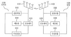
도 11 은 본 발명의 일 실시예에 적용될 수 있는 기지국 및 단말의 구성을 도시한 도면이다.BRIEF DESCRIPTION OF THE DRAWINGS The accompanying drawings, which are included to provide a further understanding of the invention and are incorporated in and constitute a part of the specification, illustrate embodiments of the invention and, together with the description, serve to explain the principles of the invention.
1 is a diagram illustrating a structure of a downlink radio frame.
2 is an exemplary diagram illustrating an example of a resource grid for one downlink slot.
3 is a diagram showing a structure of a downlink sub-frame.
4 is a diagram illustrating the structure of an uplink subframe.
5 is a configuration diagram of a wireless communication system having multiple antennas.
6 is a diagram showing a pattern of a conventional CRS and DRS.
7 is a diagram showing an example of the DM RS pattern.
8 is a diagram showing examples of a CSI-RS pattern.
9 is a diagram showing an example of a zero-power channel state information reference signal pattern.
10 is a diagram showing an example of a hopping pattern of interference measurement resources for measuring interference of an adjacent base station.
11 is a diagram illustrating a configuration of a base station and a terminal that can be applied to an embodiment of the present invention.
이하의 실시예들은 본 발명의 구성요소들과 특징들을 소정 형태로 결합한 것들이다. 각 구성요소 또는 특징은 별도의 명시적 언급이 없는 한 선택적인 것으로 고려될 수 있다. 각 구성요소 또는 특징은 다른 구성요소나 특징과 결합되지 않은 형태로 실시될 수 있다. 또한, 일부 구성요소들 및/또는 특징들을 결합하여 본 발명의 실시예를 구성할 수도 있다. 본 발명의 실시예들에서 설명되는 동작들의 순서는 변경될 수 있다. 어느 실시예의 일부 구성이나 특징은 다른 실시예에 포함될 수 있고, 또는 다른 실시예의 대응하는 구성 또는 특징과 교체될 수 있다.The following embodiments are a combination of elements and features of the present invention in a predetermined form. Each component or characteristic may be considered optional unless otherwise expressly stated. Each component or feature may be implemented in a form that is not combined with other components or features. In addition, some of the elements and / or features may be combined to form an embodiment of the present invention. The order of the operations described in the embodiments of the present invention may be changed. Some configurations or features of certain embodiments may be included in other embodiments, or may be replaced with corresponding configurations or features of other embodiments.
본 명세서에서 본 발명의 실시예들을 기지국과 단말 간의 데이터 송신 및 수신의 관계를 중심으로 설명한다. 여기서, 기지국은 단말과 직접적으로 통신을 수행하는 네트워크의 종단 노드(terminal node)로서의 의미를 갖는다. 본 문서에서 기지국에 의해 수행되는 것으로 설명된 특정 동작은 경우에 따라서는 기지국의 상위 노드(upper node)에 의해 수행될 수도 있다.Embodiments of the present invention will be described herein with reference to the relationship between data transmission and reception between a base station and a terminal. Here, the BS has a meaning as a terminal node of a network that directly communicates with the MS. The specific operation described herein as performed by the base station may be performed by an upper node of the base station, as the case may be.
즉, 기지국을 포함하는 다수의 네트워크 노드들(network nodes)로 이루어지는 네트워크에서 단말과의 통신을 위해 수행되는 다양한 동작들은 기지국 또는 기지국 이외의 다른 네트워크 노드들에 의해 수행될 수 있음은 자명하다. '기지국(BS: Base Station)'은 고정국(fixed station), Node B, eNode B(eNB), 액세스 포인트(AP: Access Point) 등의 용어에 의해 대체될 수 있다. 중계기는 Relay Node(RN), Relay Station(RS) 등의 용어에 의해 대체될 수 있다. 또한, '단말(Terminal)'은 UE(User Equipment), MS(Mobile Station), MSS(Mobile Subscriber Station), SS(Subscriber Station) 등의 용어로 대체될 수 있다.That is, it is apparent that various operations performed for communication with a terminal in a network composed of a plurality of network nodes including a base station can be performed by a network node other than the base station or the base station. A 'base station (BS)' may be replaced by a term such as a fixed station, a Node B, an eNode B (eNB), an access point (AP) Repeaters can be replaced by terms such as Relay Node (RN), Relay Station (RS), and so on. The term 'terminal' may be replaced with terms such as User Equipment (UE), Mobile Station (MS), Mobile Subscriber Station (MSS), and Subscriber Station (SS).
이하의 설명에서 사용되는 특정 용어들은 본 발명의 이해를 돕기 위해서 제공된 것이며, 이러한 특정 용어의 사용은 본 발명의 기술적 사상을 벗어나지 않는 범위에서 다른 형태로 변경될 수 있다.The specific terminology used in the following description is provided to aid understanding of the present invention, and the use of such specific terminology may be changed into other forms without departing from the technical idea of the present invention.
몇몇 경우, 본 발명의 개념이 모호해지는 것을 피하기 위하여 공지의 구조 및 장치는 생략되거나, 각 구조 및 장치의 핵심기능을 중심으로 한 블록도 형식으로 도시될 수 있다. 또한, 본 명세서 전체에서 동일한 구성요소에 대해서는 동일한 도면 부호를 사용하여 설명한다.In some instances, well-known structures and devices may be omitted or may be shown in block diagram form, centering on the core functionality of each structure and device, to avoid obscuring the concepts of the present invention. In the following description, the same components are denoted by the same reference numerals throughout the specification.
본 발명의 실시예들은 무선 접속 시스템들인 IEEE 802 시스템, 3GPP 시스템, 3GPP LTE 및 LTE-A(LTE-Advanced)시스템 및 3GPP2 시스템 중 적어도 하나에 개시된 표준 문서들에 의해 뒷받침될 수 있다. 즉, 본 발명의 실시예들 중 본 발명의 기술적 사상을 명확히 드러내기 위해 설명하지 않은 단계들 또는 부분들은 상기 문서들에 의해 뒷받침될 수 있다. 또한, 본 문서에서 개시하고 있는 모든 용어들은 상기 표준 문서에 의해 설명될 수 있다.Embodiments of the present invention may be supported by standard documents disclosed in at least one of the IEEE 802 systems, 3GPP systems, 3GPP LTE and LTE-Advanced (LTE-Advanced) systems, and 3GPP2 systems, which are wireless access systems. That is, the steps or portions of the embodiments of the present invention that are not described in order to clearly illustrate the technical idea of the present invention can be supported by the documents. In addition, all terms disclosed in this document may be described by the standard document.
이하의 기술은 CDMA(Code Division Multiple Access), FDMA(Frequency Division Multiple Access), TDMA(Time Division Multiple Access), OFDMA(Orthogonal Frequency Division Multiple Access), SC-FDMA(Single Carrier Frequency Division Multiple Access) 등과 같은 다양한 무선 접속 시스템에 사용될 수 있다. CDMA 는 UTRA(Universal Terrestrial Radio Access)나 CDMA2000 과 같은 무선 기술(radio technology)로 구현될 수 있다. TDMA 는 GSM(Global System for Mobile communications)/GPRS(General Packet Radio Service)/EDGE(Enhanced Data Rates for GSM Evolution)와 같은 무선 기술로 구현될 수 있다. OFDMA 는 IEEE 802.11 (Wi-Fi), IEEE 802.16 (WiMAX), IEEE 802-20, E-UTRA(Evolved UTRA) 등과 같은 무선 기술로 구현될 수 있다. UTRA 는 UMTS(Universal Mobile Telecommunications System)의 일부이다. 3GPP(3rd Generation Partnership Project) LTE(long term evolution)는 E-UTRA를 사용하는 E-UMTS(Evolved UMTS)의 일부로써, 하향링크에서 OFDMA 를 채용하고 상향링크에서 SC-FDMA 를 채용한다. LTE-A(Advanced)는 3GPP LTE 의 진화이다. WiMAX 는 IEEE 802.16e 규격(WirelessMAN-OFDMA Reference System) 및 발전된 IEEE 802.16m 규격(WirelessMAN-OFDMA Advanced system)에 의하여 설명될 수 있다. 명확성을 위하여 이하에서는 3GPP LTE 및 LTE-A 표준을 위주로 설명하지만 본 발명의 기술적 사상이 이에 제한되는 것은 아니다.The following description will be made on the assumption that the present invention is applicable to a CDMA system such as Code Division Multiple Access (CDMA), Frequency Division Multiple Access (FDMA), Time Division Multiple Access (TDMA), Orthogonal Frequency Division Multiple Access (OFDMA), and Single Carrier Frequency Division Multiple Access And can be used in various wireless access systems. CDMA may be implemented in radio technology such as Universal Terrestrial Radio Access (UTRA) or CDMA2000. The TDMA may be implemented in a wireless technology such as Global System for Mobile communications (GSM) / General Packet Radio Service (GPRS) / Enhanced Data Rates for GSM Evolution (EDGE). OFDMA may be implemented in wireless technologies such as IEEE 802.11 (Wi-Fi), IEEE 802.16 (WiMAX), IEEE 802-20, and Evolved UTRA (E-UTRA). UTRA is part of the Universal Mobile Telecommunications System (UMTS). 3GPP (3rd Generation Partnership Project) LTE (Long Term Evolution) is a part of E-UMTS (Evolved UMTS) using E-UTRA, adopting OFDMA in downlink and SC-FDMA in uplink. LTE-A (Advanced) is the evolution of 3GPP LTE. WiMAX can be described by the IEEE 802.16e standard (WirelessMAN-OFDMA Reference System) and the advanced IEEE 802.16m standard (WirelessMAN-OFDMA Advanced system). For clarity, the 3GPP LTE and LTE-A standards are mainly described below, but the technical idea of the present invention is not limited thereto.
도 1 을 참조하여 하향링크 무선 프레임의 구조에 대하여 설명한다.The structure of the downlink radio frame will be described with reference to FIG.
셀룰라 OFDM 무선 패킷 통신 시스템에서, 상/하향링크 데이터 패킷 전송은 서브프레임 (Subframe) 단위로 이루어지며, 한 서브프레임은 다수의 OFDM 심볼을 포함하는 일정 시간 구간으로 정의된다. 3GPP LTE 표준에서는 FDD(Frequency Division Duplex)에 적용 가능한 타입 1 무선 프레임(radio frame) 구조와 TDD(Time Division Duplex)에 적용 가능한 타입 2 의 무선 프레임 구조를 지원한다.In a cellular OFDM wireless packet communication system, uplink / downlink data packet transmission is performed on a subframe basis, and one subframe is defined as a predetermined time interval including a plurality of OFDM symbols. The 3GPP LTE standard supports a
도 1 은 타입 1 무선 프레임의 구조를 나타내는 도면이다. 하향링크 무선 프레임(radio frame)은 10 개의 서브프레임(subframe)으로 구성되고, 하나의 서브프레임은 시간 영역(time domain)에서 2 개의 슬롯(slot)으로 구성된다. 하나의 서브프레임이 전송되는 데 걸리는 시간을 TTI(transmission time interval)이라 하고, 예를 들어 하나의 서브프레임의 길이는 1ms 이고, 하나의 슬롯의 길이는 0.5ms 일 수 있다. 하나의 슬롯은 시간 영역에서 복수의 OFDM 심볼을 포함하고, 주파수 영역에서 다수의 자원블록(Resource Block; RB)을 포함한다. 3GPP LTE 시스템에서는 하향링크에서 OFDMA 를 사용하므로, OFDM 심볼이 하나의 심볼 구간을 나타낸다. OFDM 심볼은 또한 SC-FDMA 심볼 또는 심볼 구간으로 칭하여질 수도 있다. 자원 블록(Resource Block; RB)은 자원 할당 단위이고, 하나의 슬롯에서 복수개의 연속적인 부반송파(subcarrier)를 포함할 수 있다.1 is a diagram showing the structure of a
하나의 슬롯에 포함되는 OFDM 심볼의 수는 CP(Cyclic Prefix)의 구성(configuration)에 따라 달라질 수 있다. CP 에는 확장된 CP(extended CP)와 일반 CP(normal CP)가 있다. 예를 들어, OFDM 심볼이 일반 CP 에 의해 구성된 경우, 하나의 슬롯에 포함되는 OFDM 심볼의 수는 7 개일 수 있다. OFDM 심볼이 확장된 CP 에 의해 구성된 경우, 한 OFDM 심볼의 길이가 늘어나므로, 한 슬롯에 포함되는 OFDM 심볼의 수는 일반 CP 인 경우보다 적다. 확장된 CP 의 경우에, 예를 들어, 하나의 슬롯에 포함되는 OFDM 심볼의 수는 6 개일 수 있다. 단말이 빠른 속도로 이동하는 등의 경우와 같이 채널상태가 불안정한 경우, 심볼간 간섭을 더욱 줄이기 위해 확장된 CP 가 사용될 수 있다.The number of OFDM symbols included in one slot may vary according to the configuration of a CP (Cyclic Prefix). The CP has an extended CP and a normal CP. For example, when an OFDM symbol is configured by a general CP, the number of OFDM symbols included in one slot may be seven. When the OFDM symbol is configured by an extended CP, since the length of one OFDM symbol is increased, the number of OFDM symbols included in one slot is smaller than that of a normal CP. In the case of the extended CP, for example, the number of OFDM symbols included in one slot may be six. If the channel condition is unstable, such as when the UE moves at a high speed, an extended CP may be used to further reduce inter-symbol interference.
일반 CP 가 사용되는 경우 하나의 슬롯은 7 개의 OFDM 심볼을 포함하므로, 하나의 서브프레임은 14 개의 OFDM 심볼을 포함한다. 이때, 각 서브프레임의 처음 2 개 또는 3 개의 OFDM 심볼은 PDCCH(physical downlink control channel)에 할당되고, 나머지 OFDM 심볼은 PDSCH(physical downlink shared channel)에 할당될 수 있다.When a normal CP is used, one slot includes 7 OFDM symbols, and therefore one subframe includes 14 OFDM symbols. At this time, the first two or three OFDM symbols of each subframe may be allocated to a physical downlink control channel (PDCCH), and the remaining OFDM symbols may be allocated to a physical downlink shared channel (PDSCH).
무선 프레임의 구조는 예시에 불과하고, 무선 프레임에 포함되는 서브프레임의 수 또는 서브프레임에 포함되는 슬롯의 수, 슬롯에 포함되는 심볼의 수는 다양하게 변경될 수 있다.The structure of the radio frame is merely an example, and the number of subframes included in a radio frame, the number of slots included in a subframe, and the number of symbols included in a slot can be variously changed.
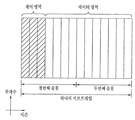
도 2 는 하나의 하향링크 슬롯에 대한 자원 그리드(resource grid)의 일례를 나타낸 예시도이다. 이는 OFDM 심볼이 일반 CP 로 구성된 경우이다. 도 2 를 참조하면, 하향링크 슬롯은 시간 영역에서 복수의 OFDM 심볼을 포함하고, 주파수 영역에서 다수의 자원블록을 포함한다. 여기서, 하나의 하향링크 슬롯은 7 OFDM 심볼을 포함하고, 하나의 자원블록은 12 부반송파를 포함하는 것을 예시적으로 기술하나, 이에 제한되는 것은 아니다. 자원 그리드 상의 각 요소(element)를 자원요소(RE)라 한다. 예를 들어, 자원 요소 a(k,l)은 k 번째 부반송파와 l 번째 OFDM 심볼에 위치한 자원 요소가 된다. 일반 CP 의 경우에, 하나의 자원블록은 12×7 자원요소를 포함한다 (확장된 CP 의 경우에는 12×6 자원요소를 포함한다). 각 부반송파의 간격은 15kHz 이므로, 하나의 자원블록은 주파수영역에서 약 180kHz 을 포함한다. NDL 은 하향링크 슬롯에 포함되는 자원블록의 수이다. NDL 의 값은 기지국의 스케줄링에 의해 설정되는 하향링크 전송 대역폭(bandwidth)에 따라 결정될 수 있다.2 is an exemplary diagram illustrating an example of a resource grid for one downlink slot. This is the case where the OFDM symbol is composed of a general CP. Referring to FIG. 2, a downlink slot includes a plurality of OFDM symbols in a time domain and a plurality of resource blocks in a frequency domain. Herein, one downlink slot includes 7 OFDM symbols, and one resource block includes 12 subcarriers by way of example, but the present invention is not limited thereto. Each element on the resource grid is called a resource element (RE). For example, the resource element a (k, l) is a resource element located in the kth subcarrier and the lth OFDM symbol. In the case of a generic CP, one resource block contains 12 × 7 resource elements (including 12 × 6 resource elements in the case of an extended CP). Since the interval of each subcarrier is 15 kHz, one resource block includes about 180 kHz in the frequency domain. The NDL is the number of resource blocks included in the downlink slot. The value of the NDL may be determined according to the downlink transmission bandwidth set by the scheduling of the base station.
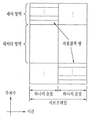
도 3 은 하향링크 서브프레임의 구조를 나타내는 도면이다. 하나의 서브프레임 내에서 첫 번째 슬롯의 앞 부분의 최대 3 개의 OFDM 심볼은 제어 채널이 할당되는 제어 영역에 해당한다. 나머지 OFDM 심볼들은 물리하향링크공유채널(Physical Downlink Shared Chancel; PDSCH)이 할당되는 데이터 영역에 해당한다. 전송의 기본 단위는 하나의 서브프레임이 된다. 즉, 2 개의 슬롯에 걸쳐 PDCCH 및 PDSCH 가 할당된다. 3GPP LTE 시스템에서 사용되는 하향링크 제어 채널들에는, 예를 들어, 물리제어포맷지시자채널(Physical Control Format Indicator Channel; PCFICH), 물리하향링크제어채널(Physical Downlink Control Channel; PDCCH), 물리 HARQ 지시자채널(Physical Hybrid automatic repeat request Indicator Channel; PHICH) 등이 있다. PCFICH 는 서브프레임의 첫 번째 OFDM 심볼에서 전송되고 서브프레임 내의 제어 채널 전송에 사용되는 OFDM 심볼의 개수에 대한 정보를 포함한다. PHICH 는 상향링크 전송의 응답으로서 HARQ ACK/NACK 신호를 포함한다. PDCCH 를 통하여 전송되는 제어 정보를 하향링크제어정보(Downlink Control Information; DCI)라 한다. DCI 는 상향링크 또는 하향링크 스케줄링 정보를 포함하거나 임의의 단말 그룹에 대한 상향링크 전송 전력 제어 명령을 포함한다. PDCCH 는 하향링크공유채널(DL-SCH)의 자원 할당 및 전송 포맷, 상향링크공유채널(UL-SCH)의 자원 할당 정보, 페이징채널(PCH)의 페이징 정보, DL-SCH 상의 시스템 정보, PDSCH 상으로 전송되는 임의접속응답(Random Access Response)과 같은 상위계층 제어 메시지의 자원 할당, 임의의 단말 그룹 내의 개별 단말에 대한 전송 전력 제어 명령의 세트, 전송 전력 제어 정보, VoIP(Voice over IP)의 활성화 등을 포함할 수 있다. 복수의 PDCCH 가 제어 영역 내에서 전송될 수 있다. 단말은 복수의 PDCCH 를 모니터링할 수 있다. PDCCH 는 하나 이상의 연속하는 제어채널요소(Control Channel Element; CCE)의 조합으로 전송된다. CCE 는 무선 채널의 상태에 기초한 코딩 레이트로 PDCCH 를 제공하기 위해 사용되는 논리 할당 단위이다. CCE 는 복수개의 자원 요소 그룹에 대응한다. PDCCH 의 포맷과 이용가능한 비트 수는 CCE 의 개수와 CCE 에 의해 제공되는 코딩 레이트 간의 상관관계에 따라서 결정된다. 기지국은 단말에게 전송되는 DCI 에 따라서 PDCCH 포맷을 결정하고, 제어 정보에 순환잉여검사(Cyclic Redundancy Check; CRC)를 부가한다. CRC 는 PDCCH 의 소유자 또는 용도에 따라 무선 네트워크 임시 식별자(Radio Network Temporary Identifier; RNTI)라 하는 식별자로 마스킹된다. PDCCH 가 특정 단말에 대한 것이면, 단말의 cell-RNTI(C-RNTI) 식별자가 CRC에 마스킹될 수 있다. 또는, PDCCH 가 페이징 메시지에 대한 것이면, 페이징 지시자 식별자(Paging Indicator Identifier; P-RNTI)가 CRC 에 마스킹될 수 있다. PDCCH 가 시스템 정보(보다 구체적으로, 시스템 정보 블록(SIB))에 대한 것이면, 시스템 정보 식별자 및 시스템 정보 RNTI(SI-RNTI)가 CRC 에 마스킹될 수 있다. 단말의 임의 접속 프리앰블의 전송에 대한 응답인 임의접속응답을 나타내기 위해, 임의접속-RNTI(RA-RNTI)가 CRC 에 마스킹될 수 있다.3 is a diagram showing a structure of a downlink sub-frame. In a subframe, a maximum of three OFDM symbols in the first part of the first slot corresponds to a control area to which a control channel is allocated. The remaining OFDM symbols correspond to a data area to which a Physical Downlink Shared Chanel (PDSCH) is allocated. The basic unit of transmission is one subframe. That is, PDCCH and PDSCH are allocated over two slots. The downlink control channels used in the 3GPP LTE system include, for example, a physical control format indicator channel (PCFICH), a physical downlink control channel (PDCCH), a physical HARQ indicator channel (Physical Hybrid Automatic Repeat Request Indicator Channel (PHICH)). The PCFICH includes information on the number of OFDM symbols transmitted in the first OFDM symbol of the subframe and used for control channel transmission in the subframe. The PHICH includes an HARQ ACK / NACK signal as a response to the uplink transmission. The control information transmitted through the PDCCH is referred to as downlink control information (DCI). The DCI includes uplink or downlink scheduling information or includes an uplink transmission power control command for an arbitrary terminal group. The PDCCH includes a resource allocation and transmission format of a downlink shared channel (DL-SCH), resource allocation information of an uplink shared channel (UL-SCH), paging information of a paging channel (PCH), system information on a DL- A set of transmission power control commands for individual terminals in an arbitrary terminal group, transmission power control information, activation of VoIP (Voice over IP), resource allocation of upper layer control messages such as random access response And the like. A plurality of PDCCHs may be transmitted within the control domain. The UE can monitor a plurality of PDCCHs. The PDCCH is transmitted in a combination of one or more contiguous Control Channel Elements (CCEs). The CCE is a logical allocation unit used to provide the PDCCH with a coding rate based on the state of the wireless channel. The CCE corresponds to a plurality of resource element groups. The format of the PDCCH and the number of available bits are determined according to the correlation between the number of CCEs and the coding rate provided by the CCE. The base station determines the PDCCH format according to the DCI transmitted to the UE and adds a cyclic redundancy check (CRC) to the control information. The CRC is masked with an identifier called a Radio Network Temporary Identifier (RNTI) according to the owner or use of the PDCCH. If the PDCCH is for a particular UE, the cell-RNTI (C-RNTI) identifier of the UE may be masked in the CRC. Alternatively, if the PDCCH is for a paging message, a Paging Indicator Identifier (P-RNTI) may be masked in the CRC. If the PDCCH is for system information (more specifically, the System Information Block (SIB)), the system information identifier and the system information RNTI (SI-RNTI) may be masked to the CRC. A random access-RNTI (RA-RNTI) may be masked to the CRC to indicate a random access response that is a response to the transmission of the UE's random access preamble.
도 4 는 상향링크 서브프레임의 구조를 나타내는 도면이다. 상향링크 서브프레임은 주파수 영역에서 제어 영역과 데이터 영역으로 분할될 수 있다. 제어 영역에는 상향링크 제어 정보를 포함하는 물리상향링크제어채널(Physical Uplink Control Channel; PUCCH)이 할당된다. 데이터 영역에는 사용자 데이터를 포함하는 물리상향 링크공유채널(Physical uplink shared channel; PUSCH)이 할당된다. 단일 반송파 특성을 유지하기 위해서, 하나의 단말은 PUCCH 와 PUSCH 를 동시에 전송하지 않는다. 하나의 단말에 대한 PUCCH 는 서브프레임에서 자원블록 쌍(RB pair)에 할당된다. 자원블록 쌍에 속하는 자원블록들은 2 슬롯에 대하여 상이한 부반송파를 차지한다. 이를 PUCCH 에 할당되는 자원블록 쌍이 슬롯 경계에서 주파수-호핑(frequency-hopped) 된다고 한다.4 is a diagram illustrating the structure of an uplink subframe. The UL subframe may be divided into a control region and a data region in the frequency domain. A physical uplink control channel (PUCCH) including uplink control information is allocated to the control region. A physical uplink shared channel (PUSCH) including user data is allocated to the data area. To maintain a single carrier characteristic, one terminal does not transmit PUCCH and PUSCH at the same time. A PUCCH for one terminal is allocated to a resource block pair (RB pair) in a subframe. Resource blocks belonging to a resource block pair occupy different subcarriers for two slots. It is assumed that the resource block pair allocated to the PUCCH is frequency-hopped at the slot boundary.
다중안테나(MIMO) 시스템의 모델링Modeling of Multi-antenna (MIMO) Systems
MIMO((Multiple Input Multiple Output) 시스템은 다중 송신 안테나와 다중 수신 안테나를 사용하여 데이터의 송수신 효율을 향상시키는 시스템이다. MIMO 기술은 전체 메시지를 수신하기 위해 단일 안테나 경로에 의존하지 않고, 복수개의 안테나를 통해 수신되는 복수개의 데이터 조각들을 조합하여 전체 데이터를 수신할 수 있다.A MIMO (Multiple Input Multiple Output) system is a system that improves the transmission / reception efficiency of data using multiple transmit antennas and multiple receive antennas. The MIMO technique does not rely on a single antenna path to receive the entire message, And can receive the entire data.
MIMO 기술에는 공간 다이버시티(Spatial diversity) 기법과 공간 다중화(Spatial multiplexing) 기법 등이 있다. 공간 다이버시티 기법은 다이버시티 이득(gain)을 통해 전송 신뢰도(reliability)를 높이거나 셀 반경을 넓힐 수 있어, 고속으로 이동하는 단말에 대한 데이터 전송에 적합하다. 공간 다중화 기법은 서로 다른 데이터를 동시에 전송함으로써 시스템의 대역폭을 증가시키지 않고 데이터 전송률을 증가시킬 수 있다.The MIMO technique includes a spatial diversity technique and a spatial multiplexing technique. The spatial diversity scheme can increase transmission reliability or diversity gain through diversity gain and is suitable for data transmission to a terminal moving at a high speed. Spatial multiplexing can increase the data rate without increasing the bandwidth of the system by transmitting different data at the same time.
도 5 는 다중안테나를 갖는 무선 통신 시스템의 구성도이다. 도 5(a)에 도시된 바와 같이 송신 안테나의 수를 NT 개로, 수신 안테나의 수를 NR 개로 늘리면, 송신기나 수신기에서만 다수의 안테나를 사용하게 되는 경우와 달리 안테나 수에 비례하여 이론적인 채널 전송 용량이 증가한다. 따라서, 전송 레이트를 향상시키고 주파수 효율을 획기적으로 향상시킬 수 있다. 채널 전송 용량이 증가함에 따라, 전송 레이트는 이론적으로 단일 안테나 이용시의 최대 전송 레이트(Ro)에 레이트 증가율(Ri)이 곱해진 만큼 증가할 수 있다.5 is a configuration diagram of a wireless communication system having multiple antennas. As shown in FIG. 5A, when the number of transmission antennas is increased to NT and the number of reception antennas is increased to NR, unlike the case where a plurality of antennas are used only in a transmitter and a receiver, a theoretical channel transmission Capacity increases. Therefore, the transmission rate can be improved and the frequency efficiency can be remarkably improved. As the channel transmission capacity increases, the transmission rate can theoretically increase by the rate of rate increase Ri multiplied by the maximum transmission rate Ro in single antenna use.
![]()
![]()
예를 들어, 4 개의 송신 안테나와 4 개의 수신 안테나를 이용하는 MIMO 통신 시스템에서는 단일 안테나 시스템에 비해 이론상 4 배의 전송 레이트를 획득할 수 있다. 다중안테나 시스템의 이론적 용량 증가가 90 년대 중반에 증명된 이후 이를 실질적인 데이터 전송률 향상으로 이끌어 내기 위한 다양한 기술들이 현재까지 활발히 연구되고 있다. 또한, 몇몇 기술들은 이미 3 세대 이동 통신과 차세대 무선랜 등의 다양한 무선 통신의 표준에 반영되고 있다.For example, in a MIMO communication system using four transmit antennas and four receive antennas, it is possible to obtain a transmission rate four times higher than the single antenna system. After the theoretical capacity increase of the multi-antenna system has been proved in the mid-90s, various techniques have been actively researched to bring it up to practical data rate improvement. In addition, several technologies have already been reflected in various wireless communication standards such as 3G mobile communication and next generation wireless LAN.
현재까지의 다중안테나 관련 연구 동향을 살펴보면 다양한 채널 환경 및 다중접속 환경에서의 다중안테나 통신 용량 계산 등과 관련된 정보 이론 측면 연구, 다중안테나 시스템의 무선 채널 측정 및 모형 도출 연구, 전송 신뢰도 향상 및 전송률 향상을 위한 시공간 신호 처리 기술 연구 등 다양한 관점에서 활발히 연구가 진행되고 있다.The research trends related to multi-antenna up to now include information theory study related to calculation of multi-antenna communication capacity in various channel environment and multiple access environment, study of wireless channel measurement and modeling of multi-antenna system, improvement of transmission reliability and improvement of transmission rate And research on space-time signal processing technology.
다중안테나 시스템에서의 통신 방법을 수학적 모델링을 이용하여 보다 구체적으로 설명한다. 상기 시스템에는 NT 개의 송신 안테나와 NR 개의 수신 안테나가 존재한다고 가정한다.A communication method in a multi-antenna system will be described in more detail using mathematical modeling. It is assumed that there are NT transmit antennas and NR receive antennas in the system.
송신 신호를 살펴보면, NT 개의 송신 안테나가 있는 경우 전송 가능한 최대 정보는 NT 개이다. 전송 정보는 다음과 같이 표현될 수 있다.Looking at the transmitted signal, if there are NT transmit antennas, the maximum transmittable information is NT. The transmission information can be expressed as follows.
![]()
![]()
각각의 전송 정보 ![]()
![]()
![]()
![]()
![]()
![]()
또한, ![]()
![]()

전송전력이 조정된 정보 벡터(Information vector) ![]()
![]()
![]()
![]()
![]()
![]()

여기에서, w ij는 i 번째 송신 안테나와 j 번째 정보간의 가중치를 의미한다. W는 프리코딩 행렬이라고도 불린다.Here, w ij denotes a weight between the i-th transmit antenna and the j-th information. W is also referred to as a precoding matrix.
한편, 송신신호 x 는 2 가지 경우(예를 들어, 공간 다이버시티 및 공간 다중화)에 따라 다른 방법으로 고려될 수 있다. 공간 다중화의 경우, 상이한 신호가 다중화되고 다중화된 신호가 수신측으로 전송되어, 정보 벡터(들)의 요소(element)가 상이한 값을 가진다. 한편, 공간 다이버시티의 경우에는, 동일한 신호가 복수개의 채널 경로를 통하여 반복적으로 전송되어, 정보 벡터(들)의 요소가 동일한 값을 가진다. 물론, 공간 다중화 및 공간 다이버시티 기법의 조합 역시 고려할 수 있다. 즉, 동일한 신호가 예를 들어 3 개의 전송 안테나를 통해 공간 다이버시티 기법에 따라 전송되고, 나머지 신호들은 공간 다중화되어 수신측으로 전송될 수도 있다.On the other hand, the transmission signal x can be considered in different ways depending on two cases (for example, spatial diversity and spatial multiplexing). In the case of spatial multiplexing, different signals are multiplexed and the multiplexed signal is transmitted to the receiving side, so that the elements of the information vector (s) have different values. On the other hand, in the case of spatial diversity, the same signal is repeatedly transmitted through a plurality of channel paths, so that the elements of the information vector (s) have the same value. Of course, a combination of spatial multiplexing and spatial diversity techniques may also be considered. That is, the same signal may be transmitted according to a spatial diversity scheme, for example, through three transmission antennas, and the remaining signals may be spatially multiplexed and transmitted to the receiving side.
NR 개의 수신 안테나가 있는 경우 각 안테나의 수신신호 ![]()
![]()
![]()
![]()
다중안테나 무선 통신 시스템에서 채널을 모델링하는 경우, 채널은 송수신 안테나 인덱스에 따라 구분될 수 있다. 송신 안테나 j 로부터 수신 안테나 i 를 거치는 채널을 h ij로 표시하기로 한다. h ij에서, 인덱스의 순서가 수신 안테나 인덱스가 먼저, 송신 안테나의 인덱스가 나중임에 유의한다.When a channel is modeled in a multi-antenna wireless communication system, the channel may be classified according to the transmission / reception antenna index. And the channel through the reception antenna i from the transmission antenna j is denoted by h ij . In h ij , note that the order of the index is the receive antenna index and the index of the transmit antenna.
도 5(b)에 NT 개의 송신 안테나에서 수신 안테나 i 로의 채널을 도시하였다. 상기 채널을 묶어서 벡터 및 행렬 형태로 표시할 수 있다. 도 5(b)에서, 총 NT 개의 송신 안테나로부터 수신 안테나 i 로 도착하는 채널은 다음과 같이 나타낼 수 있다.FIG. 5 (b) shows a channel from NT transmit antennas to receive antennas i. The channels can be grouped and displayed in vector and matrix form. In FIG. 5 (b), a channel arriving from a total of NT transmit antennas to receive antennas i may be expressed as follows.
![]()
![]()
따라서, NT 개의 송신 안테나로부터 NR 개의 수신 안테나로 도착하는 모든 채널은 다음과 같이 표현될 수 있다.Therefore, all channels arriving from the NT transmit antennas to the NR receive antennas can be expressed as:

실제 채널에는 채널 행렬 H를 거친 후에 백색잡음(AWGN; Additive White Gaussian Noise)이 더해진다. NR 개의 수신 안테나 각각에 더해지는 백색잡음 ![]()
![]()
![]()
![]()
상술한 수식 모델링을 통해 수신신호는 다음과 같이 표현될 수 있다.Through the above-described equation modeling, the received signal can be expressed as follows.

채널 상태를 나타내는 채널 행렬 H의 행과 열의 수는 송수신 안테나의 수에 의해 결정된다. 채널 행렬 H에서 행의 수는 수신 안테나의 수 NR 과 같고, 열의 수는 송신 안테나의 수 NT 와 같다. 즉, 채널 행렬 H는 행렬이 NR×NT 된다.The number of rows and columns of the channel matrix H representing the channel state is determined by the number of transmitting and receiving antennas. The number of rows in channel matrix H equals the number of receive antennas NR, and the number of columns equals the number NT of transmit antennas. That is, the channel matrix H is NR × NT.
행렬의 랭크(rank)는 서로 독립인(independent) 행 또는 열의 개수 중에서 최소 개수로 정의된다. 따라서, 행렬의 랭크는 행 또는 열의 개수 보다 클 수 없다. 채널 행렬 H의 랭크(rank(H))는 다음과 같이 제한된다.The rank of a matrix is defined as the minimum number of independent rows or columns. Thus, the rank of the matrix can not be greater than the number of rows or columns. The rank ( rank (H)) of the channel matrix H is limited as follows.
![]()
![]()
MIMO 전송에 있어서 '랭크(Rank)' 는 독립적으로 신호를 전송할 수 있는 경로의 수를 나타내며, '레이어(layer)의 개수' 는 각 경로를 통해 전송되는 신호 스트림의 개수를 나타낸다. 일반적으로 송신단은 신호 전송에 이용되는 랭크 수에 대응하는 개수의 레이어를 전송하기 때문에 특별한 언급이 없는 한 랭크는 레이어 개수와 동일한 의미를 가진다.In MIMO transmission, 'rank' represents the number of paths that can independently transmit signals, and 'number of layers' represents the number of signal streams transmitted through each path. In general, since the transmitting end transmits a number of layers corresponding to the number of ranks used for signal transmission, the rank has the same meaning as the number of layers unless otherwise specified.
참조 신호 (Reference Signal; RS)A reference signal (RS)
무선 통신 시스템에서 패킷을 전송할 때, 전송되는 패킷은 무선 채널을 통해서 전송되기 때문에 전송과정에서 신호의 왜곡이 발생할 수 있다. 왜곡된 신호를 수신측에서 올바로 수신하기 위해서는 채널 정보를 이용하여 수신 신호에서 왜곡을 보정하여야 한다. 채널 정보를 알아내기 위해서, 송신측과 수신측에서 모두 알고 있는 신호를 전송하여, 상기 신호가 채널을 통해 수신될 때의 왜곡 정도를 가지고 채널 정보를 알아내는 방법을 주로 사용한다. 상기 신호를 파일럿 신호 (Pilot Signal) 또는 참조 신호 (Reference Signal)라고 한다.When a packet is transmitted in a wireless communication system, since the transmitted packet is transmitted through a wireless channel, signal distortion may occur in the transmission process. In order to properly receive the distorted signal at the receiving side, the distortion should be corrected in the received signal using the channel information. In order to determine the channel information, a method is used in which a signal known to both the transmitting side and the receiving side is transmitted, and channel information is detected with a degree of distortion when the signal is received through the channel. The signal is referred to as a pilot signal or a reference signal.
다중안테나를 사용하여 데이터를 송수신하는 경우에는 각 송신 안테나와 수신 안테나 사이의 채널 상황을 알아야 올바른 신호를 수신할 수 있다. 따라서, 각 송신 안테나 별로 별도의 참조 신호가 존재하여야 한다.When transmitting and receiving data using multiple antennas, it is necessary to know the channel condition between each transmitting antenna and the receiving antenna so that a correct signal can be received. Therefore, there is a separate reference signal for each transmission antenna.
이동 통신 시스템에서 참조신호(RS)는 그 목적에 따라 크게 두 가지로 구분될 수 있다. 하나는 채널 정보 획득을 위해 사용되는 RS 이고, 다른 하나는 데이터 복조를 위해 사용되는 RS 이다. 전자는 단말이 하향 링크 채널 정보를 획득하도록 하기 위한 RS 이므로 광대역으로 전송되어야 하고, 특정 서브프레임에서 하향링크 데이터를 수신하지 않는 단말이라도 해당 RS 를 수신하고 측정할 수 있어야 한다. 이러한 RS 는 핸드 오버 등을 위한 측정 등을 위해서도 사용된다. 후자는 기지국이 하향링크를 보낼 때 해당 자원에 함께 보내는 RS 로서, 단말은 해당 RS 를 수신함으로써 채널 추정을 할 수 있고, 따라서 데이터를 복조할 수 있게 된다. 이러한 RS 는 데이터가 전송되는 영역에 전송되어야 한다.In the mobile communication system, the reference signal RS can be roughly classified into two types according to its purpose. One is an RS used for channel information acquisition and the other is an RS used for data demodulation. Since the former is an RS for allowing the UE to acquire downlink channel information, it should be transmitted in a wide band, and even a terminal not receiving downlink data in a specific subframe must be able to receive and measure the corresponding RS. These RSs are also used for measurements for handover and the like. The latter is an RS transmitted together with a corresponding resource when the BS transmits the downlink, and the UE can perform channel estimation by receiving the corresponding RS, and thus can demodulate the data. These RSs must be transmitted in the area where data is transmitted.
기존의 3GPP LTE(예를 들어, 3GPP LTE 릴리즈-8) 시스템에서는 유니캐스트(unicast) 서비스를 위해서 2 가지 종류의 하향링크 RS 를 정의한다. 그 중 하나는 공용 참조신호(Common RS; CRS)이고, 다른 하나는 전용 참조신호(Dedicated RS; DRS)이다. CRS 는 채널 상태에 대한 정보 획득 및 핸드오버 등을 위한 측정 등을 위해서 사용되고, 셀-특정(cell-specific) RS 라고 칭할 수도 있다. DRS 는 데이터 복조를 위해 사용되고, 단말-특정(UE-specific) RS 라고 칭할 수도 있다. 기존의 3GPP LTE 시스템에서 DRS 는 데이터 복조용으로만 사용되며 CRS 는 채널 정보 획득 및 데이터 복조의 두 가지 목적으로 다 사용될 수 있다.In the existing 3GPP LTE (e.g., 3GPP LTE Release-8) system, two kinds of downlink RSs are defined for a unicast service. One of them is a common RS (CRS), and the other is a dedicated RS (DRS). The CRS is used for acquiring information on the channel status and for measuring for handover, etc., and may also be referred to as a cell-specific RS. The DRS is used for data demodulation and may also be referred to as a UE-specific RS. In the existing 3GPP LTE system, DRS is used only for data demodulation and CRS can be used for both channel information acquisition and data demodulation.
CRS 는 셀-특정으로 전송되는 RS 이며, 광대역(wideband)에 대해서 매 서브프레임마다 전송된다. CRS 는 기지국의 전송 안테나 개수에 따라서 최대 4 개의 안테나 포트에 대해서 전송될 수 있다. 예를 들어 기지국의 송신 안테나의 개수가 두 개일 경우, 0 번과 1 번 안테나 포트에 대한 CRS 가 전송되고, 네 개인 경우 0~3 번 안테나 포트에 대한 CRS 가 각각 전송된다.CRS is an RS transmitted in a cell-specific manner, and is transmitted in every subframe for a wideband. The CRS can be transmitted for up to four antenna ports, depending on the number of transmit antennas of the base station. For example, if the number of transmit antennas of the base station is two, the CRS is transmitted for the
도 6 은 기지국이 4 개의 전송 안테나를 지원하는 시스템에서 하나의 자원블록 (일반 CP 의 경우, 시간 상으로 14 개의 OFDM 심볼 × 주파수 상으로 12 부반송파) 상에서 CRS 및 DRS 의 패턴을 나타내는 도면이다. 도 6 에서 'R0', 'R1', 'R2' 및 'R3' 로 표시된 자원 요소(RE)는, 각각 안테나 포트 인덱스 0, 1, 2 및 3 에 대한 CRS 의 위치를 나타낸다. 한편, 도 6 에서 'D'로 표시된 자원 요소는 LTE 시스템에서 정의되는 DRS 의 위치를 나타낸다.6 is a diagram showing a pattern of CRS and DRS on one resource block (14 OFDM symbols in time × 12 subcarriers on frequency in a normal CP) in a system in which a base station supports four transmit antennas. In FIG. 6, the resource elements RE denoted by 'R0', 'R1', 'R2' and 'R3' represent the positions of the CRSs for the
LTE 시스템의 진화 발전된 형태의 LTE-A 시스템에서는, 하향링크에서 최대 8 개의 송신 안테나를 지원할 수 있다. 따라서, 최대 8 개 송신 안테나에 대한 RS 역시 지원되어야 한다. LTE 시스템에서의 하향링크 RS는 최대 4개의 안테나 포트에 대해서만 정의되어 있으므로, LTE-A 시스템에서 기지국이 4 개 이상 최대 8 개의 하향 링크 송신 안테나를 가질 경우 이들 안테나 포트들에 대한 RS 가 추가적으로 정의되어야 한다. 최대 8 개의 송신 안테나 포트에 대한 RS 로서, 채널 측정을 위한 RS 와 데이터 복조를 위한 RS 두 가지가 모두 고려되어야 한다.Evolution of LTE System In the advanced type of LTE-A system, up to 8 transmit antennas can be supported in the downlink. Therefore, RS for up to 8 transmit antennas must also be supported. Since the downlink RS in the LTE system is defined only for a maximum of four antenna ports, if the base station has more than four downlink transmission antennas in the LTE-A system, RSs for the antenna ports are additionally defined do. As RSs for up to eight transmit antenna ports, both RS for channel measurement and RS for data demodulation must be considered.
LTE-A 시스템을 설계함에 있어서 중요한 고려 사항 중 하나는 역방향 호환성(backward compatibility)이다. 역방향 호환성이란, 기존의 LTE 단말이 LTE-A 시스템에서도 올바르게 동작하도록 지원하는 것을 의미한다. RS 전송 관점에서 보았을 때, LTE 표준에서 정의되어 있는 CRS 가 전 대역으로 매 서브프레임마다 전송되는 시간-주파수 영역에 최대 8 개의 송신 안테나 포트에 대한 RS 를 추가하는 경우, RS 오버헤드가 지나치게 커지게 된다. 따라서, 최대 8 안테나 포트에 대한 RS 를 새롭게 설계함에 있어서 RS 오버헤드를 줄이는 것이 고려되어야 한다.One of the important considerations in designing an LTE-A system is backward compatibility. Backward compatibility means that existing LTE terminals support proper operation in the LTE-A system. From the viewpoint of RS transmission, when RSs for up to 8 transmit antenna ports are added to the time-frequency domain in which the CRS defined in the LTE standard is transmitted for every subframe in all bands, RS overhead is excessively large do. Therefore, reducing the RS overhead in the new RS design for up to 8 antenna ports should be considered.
LTE-A 시스템에서 새롭게 도입되는 RS 는 크게 2 가지로 분류할 수 있다. 그 중 하나는 전송 랭크, 변조및코딩기법(Modulation and Coding Scheme; MCS), 프리코딩 행렬인덱스(Precoding Matrix Index; PMI) 등의 선택을 위한 채널 측정 목적의 RS 인 채널상태정보-참조신호(Channel State Information RS; CSI-RS)이고, 다른 하나는 최대 8 개의 전송 안테나를 통해 전송되는 데이터를 복조하기 위한 목적의 RS 인 복조-참조신호(DeModulation RS; DM RS)이다.The RSs newly introduced in the LTE-A system can be roughly classified into two types. One of them is a channel status information-reference signal (RS), which is an RS for channel measurement for selection of a transmission rank, a modulation and coding scheme (MCS), a precoding matrix index (PMI) The other is a demodulation RS (DM RS), which is a RS for demodulating data transmitted through up to 8 transmit antennas.
채널 측정 목적의 CSI-RS 는, 기존의 LTE 시스템에서의 CRS 가 채널 측정, 핸드오버 등의 측정 등의 목적과 동시에 데이터 복조를 위해 사용되는 것과 달리, 채널 측정 위주의 목적을 위해서 설계되는 특징이 있다. 물론 CSI-RS 역시 핸드오버 등의 측정 등의 목적으로도 사용될 수도 있다. CSI-RS 가 채널 상태에 대한 정보를 얻는 목적으로만 전송되므로, 기존의 LTE 시스템에서의 CRS 와 달리, 매 서브프레임마다 전송되지 않아도 된다. 따라서, CSI-RS 의 오버헤드를 줄이기 위하여 CSI-RS 는 시간 축상에서 간헐적으로(예를 들어, 주기적으로) 전송되도록 설계될 수 있다.The CSI-RS for channel measurement purposes is different from the CRS in the existing LTE system, which is used for data demodulation in addition to the purpose of channel measurement, handover, etc., have. Of course, the CSI-RS may also be used for measurement such as handover. Since the CSI-RS is transmitted only for the purpose of obtaining information on the channel status, unlike the CRS in the existing LTE system, it is not transmitted every subframe. Thus, in order to reduce the overhead of the CSI-RS, the CSI-RS may be designed to be transmitted intermittently (e.g., periodically) on the time axis.
만약 어떤 하향링크 서브프레임 상에서 데이터가 전송되는 경우에는, 데이터 전송이 스케줄링된 단말에게 전용으로(dedicated) DM RS 가 전송된다. 특정 단말 전용의 DM RS 는, 해당 단말이 스케줄링된 자원영역, 즉 해당 단말에 대한 데이터가 전송되는 시간-주파수 영역에서만 전송되도록 설계될 수 있다.If data is transmitted on a downlink subframe, a dedicated DM RS is transmitted to the scheduled UE for data transmission. The DM RS dedicated to a specific terminal can be designed to be transmitted only in a resource region in which the terminal is scheduled, that is, in a time-frequency region in which data for the terminal is transmitted.
도 7 은 LTE-A 시스템에서 정의되는 DM RS 패턴의 일례를 나타내는 도면이다. 도 7 에서는 하향링크 데이터가 전송되는 하나의 자원블록(일반 CP 의 경우, 시간 상으로 14 개의 OFDM 심볼 × 주파수 상으로 12 부반송파) 상에서 DM RS 가 전송되는 자원요소의 위치를 나타낸다. DM RS 는 LTE-A 시스템에서 추가적으로 정의되는 4 개의 안테나 포트(안테나 포트 인덱스 7, 8, 9 및 10)에 대하여 전송될 수 있다. 서로 다른 안테나 포트에 대한 DM RS 는 상이한 주파수 자원(부반송파) 및/또는 상이한 시간 자원(OFDM 심볼)에 위치하는 것으로 구분될 수 있다(즉, FDM 및/또는 TDM 방식으로 다중화될 수 있다). 또한, 동일한 시간-주파수 자원 상에 위치하는 서로 다른 안테나 포트에 대한 DM RS 들은 서로 직교 코드(orthogonal code)에 의해서 구분될 수 있다(즉, CDM 방식으로 다중화될 수 있다). 도 7 의 예시에서 DM RS CDM 그룹 1 로 표시된 자원요소(RE) 들에는 안테나 포트 7 및 8 에 대한 DM RS 들이 위치할 수 있고, 이들은 직교 코드에 의해 다중화될 수 있다. 마찬가지로, 도 7 의 예시에서 DM RS 그룹 2 로 표시된 자원요소들에는 안테나 포트 9 및 10 에 대한 DM RS 들이 위치할 수 있고, 이들은 직교 코드에 의해 다중화될 수 있다.7 is a diagram showing an example of a DM RS pattern defined in the LTE-A system. 7 shows a location of a resource element in which a DM RS is transmitted on one resource block in which downlink data is transmitted (in the case of a general CP, 14 OFDM symbols in time × 12 subcarriers on frequency). The DM RS may be transmitted for four antenna ports (
도 8 은 LTE-A 시스템에서 정의되는 CSI-RS 패턴의 예시들을 나타내는 도면이다. 도 8 에서는 하향링크 데이터가 전송되는 하나의 자원블록(일반 CP 의 경우, 시간 상으로 14 개의 OFDM 심볼 × 주파수 상으로 12 부반송파) 상에서 CSI-RS 가 전송되는 자원요소의 위치를 나타낸다. 어떤 하향링크 서브프레임에서 도 8(a) 내지 8(e) 중 하나의 CSI-RS 패턴이 이용될 수 있다. CSI-RS 는 LTE-A 시스템에서 추가적으로 정의되는 8 개의 안테나 포트(안테나 포트 인덱스 15, 16, 17, 18, 19, 20, 21 및 22) 에 대하여 전송될 수 있다. 서로 다른 안테나 포트에 대한 CSI-RS 는 상이한 주파수 자원(부반송파) 및/또는 상이한 시간 자원(OFDM 심볼)에 위치하는 것으로 구분될 수 있다(즉, FDM 및/또는 TDM 방식으로 다중화될 수 있다). 또한, 동일한 시간-주파수 자원 상에 위치하는 서로 다른 안테나 포트에 대한 CSI-RS 들은 서로 직교 코드(orthogonal code)에 의해서 구분될 수 있다(즉, CDM 방식으로 다중화될 수 있다). 도 8(a) 의 예시에서 CSI-RS CDM 그룹 1 로 표시된 자원요소(RE) 들에는 안테나 포트 15 및 16 에 대한 CSI-RS 들이 위치할 수 있고, 이들은 직교 코드에 의해 다중화될 수 있다. 도 8(a) 의 예시에서 CSI-RS CDM 그룹 2 로 표시된 자원요소들에는 안테나 포트 17 및 18 에 대한 CSI-RS 들이 위치할 수 있고, 이들은 직교 코드에 의해 다중화될 수 있다. 도 8(a) 의 예시에서 CSI-RS CDM 그룹 3 으로 표시된 자원요소들에는 안테나 포트 19 및 20 에 대한 CSI-RS 들이 위치할 수 있고, 이들은 직교 코드에 의해 다중화될 수 있다. 도 8(a) 의 예시에서 CSI-RS CDM 그룹 4 로 표시된 자원요소들에는 안테나 포트 21 및 22 에 대한 CSI-RS 들이 위치할 수 있고, 이들은 직교 코드에 의해 다중화될 수 있다. 도 8(a)를 기준으로 설명한 동일한 원리가 도 8(b) 내지 8(e) 에 적용될 수 있다.8 is a diagram showing examples of CSI-RS patterns defined in the LTE-A system. 8 shows a location of a resource element to which a CSI-RS is transmitted on one resource block in which downlink data is transmitted (in the case of a general CP, 14 OFDM symbols in time × 12 subcarriers in frequency). In some downlink subframes, the CSI-RS pattern of one of Figs. 8 (a) to 8 (e) can be used. The CSI-RS may be transmitted for eight antenna ports (
도 6 내지 8 의 RS 패턴들은 단지 예시적인 것이며, 본 발명의 다양한 실시예들을 적용함에 있어서 특정 RS 패턴에 한정되는 것이 아니다. 즉, 도 6 내지 8 과 다른 RS 패턴이 정의 및 사용되는 경우에도 본 발명의 다양한 실시예들은 동일하게 적용될 수 있다.The RS patterns in Figures 6 to 8 are merely illustrative and are not limited to a particular RS pattern in applying various embodiments of the present invention. That is, various embodiments of the present invention can be equally applied even when RS patterns different from those of Figs. 6 to 8 are defined and used.
한편, 참조 신호를 위한 시퀀스(sequence)는 의사-랜덤(Pseudo Random) 시퀀스 생성기를 이용하여 생성될 수 있다.Meanwhile, a sequence for a reference signal may be generated using a pseudo-random sequence generator.
의사-랜덤 시퀀스는 길이 31 의 골드(gold) 시퀀스로 정의된다. 길이 M PN 의 출력 시퀀스 c(n) 은 다음 수학식 12 와 같이 정의될 수 있다(여기서, n = 0,1,...,M PN-1).The pseudo-random sequence is defined as a gold sequence of length 31. The output sequence c ( n ) of length M PN can be defined as follows (where n = 0,1, ..., M PN -1).

여기서, N c = 1600 , 첫 번째 m-시퀀스는 x 1(0) = 1,x 1(n) = 0,n = 1,2,...,30 로 초기화된다.Here, N c = 1600, the first m- sequence x 1 (0) = 1, x 1 (n) = 0, n = 1,2, ..., is initialized to 30.
두 번째 m-시퀀스의 초기화는 시퀀스의 어플리케이션(application)에 따른 값에 따라 값을 갖는 
협력형 다중-포인트 (Cooperative Multi-Point; CoMP)Cooperative Multi-Point (CoMP)
3GPP LTE-A 시스템의 개선된 시스템 성능 요구조건에 따라서, CoMP 송수신 기술 (co-MIMO, 공동(collaborative) MIMO 또는 네트워크 MIMO 등으로 표현되기도 함)이 제안되고 있다. CoMP 기술은 셀-경계(cell-edge)에 위치한 단말의 성능을 증가시키고 평균 섹터 수율(throughput)을 증가시킬 수 있다.CoMP transmission and reception techniques (also referred to as co-MIMO, collaborative MIMO, or network MIMO, etc.) have been proposed according to the improved system performance requirements of the 3GPP LTE-A system. The CoMP technique can increase the performance of the UE located at the cell-edge and increase the average sector throughput.
일반적으로, 주파수 재사용 인자(frequency reuse factor)가 1 인 다중-셀 환경에서, 셀-간 간섭(Inter-Cell Interference; ICI)으로 인하여 셀-경계에 위치한 단말의 성능과 평균 섹터 수율이 감소될 수 있다. 이러한 ICI 를 저감하기 위하여, 기존의 LTE 시스템에서는 단말 특정 전력 제어를 통한 부분 주파수 재사용(fractional frequency reuse; FFR)과 같은 단순한 수동적인 기법을 이용하여 간섭에 의해 제한을 받은 환경에서 셀-경계에 위치한 단말이 적절한 수율 성능을 가지도록 하는 방법이 적용되었다. 그러나, 셀 당 주파수 자원 사용을 낮추기보다는, ICI 를 저감하거나 ICI 를 단말이 원하는 신호로 재사용하는 것이 보다 바람직할 수 있다. 위와 같은 목적을 달성하기 위하여, CoMP 전송 기법이 적용될 수 있다.Generally, in a multi-cell environment with a frequency reuse factor of 1, the performance of a UE located at a cell boundary due to inter-cell interference (ICI) and average sector yield may be reduced have. In order to reduce such ICI, in a conventional LTE system, a simple passive technique such as fractional frequency reuse (FFR) through UE-specific power control is used, A method of allowing the terminal to have a proper yield performance has been applied. However, rather than lowering the frequency resource usage per cell, it may be more desirable to reduce the ICI or reuse the ICI as the desired signal. In order to achieve the above object, the CoMP transmission scheme can be applied.
하향링크의 경우에 적용될 수 있는 CoMP 기법은 크게 조인트-프로세싱(joint processing; JP) 기법 및 조정 스케줄링/빔포밍 (coordinated scheduling / beamforming; CS/CB) 기법으로 분류할 수 있다.CoMP techniques that can be applied in the case of downlink can be roughly classified into a joint-processing (JP) technique and a coordinated scheduling / beamforming (CS / CB) technique.
JP 기법은 CoMP 협력 단위의 각각의 포인트(기지국)에서 데이터를 이용할 수 있다. CoMP 협력 단위는 협력 전송 기법에 이용되는 기지국들의 집합을 의미한다. JP 기법은 조인트 전송(Joint Transmission) 기법과 동적 셀 선택(Dynamic cell selection) 기법으로 분류할 수 있다.The JP technique can utilize the data at each point (base station) of the CoMP cooperating unit. The CoMP cooperative unit refers to a set of base stations used in the cooperative transmission scheme. The JP method can be classified into Joint Transmission method and Dynamic cell selection method.
조인트 전송 기법은, PDSCH 가 한번에 복수개의 포인트(CoMP 협력 단위의 일부 또는 전부)로부터 전송되는 기법을 말한다. 즉, 단일 단말로 전송되는 데이터는 복수개의 전송 포인트(transmission point, TP)로부터 동시에 전송될 수 있다. 조인트 전송 기법에 의하면, 코히어런트하게(coherently) 또는 넌-코히어런트하게(non-coherently) 수신 신호의 품질이 향상될 수 있고, 또한, 다른 단말에 대한 간섭을 능동적으로 소거할 수도 있다.The joint transmission scheme refers to a scheme in which the PDSCH is transmitted from a plurality of points (a part or all of CoMP cooperation units) at one time. That is, data transmitted to a single terminal can be simultaneously transmitted from a plurality of transmission points (TP). According to the joint transmission scheme, the quality of a coherently or non-coherently received signal may be improved and also actively cancel interference to other terminals.
동적 셀 선택 기법은, PDSCH 가 한번에 (CoMP 협력 단위의) 하나의 포인트로부터 전송되는 기법을 말한다. 즉, 특정 시점에서 단일 단말로 전송되는 데이터는 하나의 포인트로부터 전송되고, 그 시점에 협력 단위 내의 다른 포인트는 해당 단말에 대하여 데이터 전송을 하지 않으며, 해당 단말로 데이터를 전송하는 포인트는 동적으로 선택될 수 있다.The dynamic cell selection scheme refers to a scheme in which the PDSCH is transmitted from one point (at CoMP cooperation unit) at a time. That is, data transmitted to a single terminal at a specific time point is transmitted from one point, and other points in the cooperating unit at that point do not transmit data to the terminal, and points for transmitting data to the terminal are dynamically selected .
한편, CS/CB 기법에 의하면 CoMP 협력 단위들이 단일 단말에 대한 데이터 전송의 빔포밍을 협력적으로 수행할 수 있다. 여기서, 데이터는 서빙 셀에서만 전송되지만, 사용자 스케줄링/빔포밍은 해당 CoMP 협력 단위의 셀들의 조정에 의하여 결정될 수 있다.Meanwhile, according to the CS / CB scheme, CoMP cooperation units can cooperatively perform beamforming of data transmission to a single terminal. Here, the data is transmitted only in the serving cell, but the user scheduling / beamforming can be determined by adjusting the cells of the CoMP cooperation unit.
한편, 상향링크의 경우에, 조정(coordinated) 다중-포인트 수신은 지리적으로 떨어진 복수개의 포인트들의 조정에 의해서 전송된 신호를 수신하는 것을 의미한다. 상향링크의 경우에 적용될 수 있는 CoMP 기법은 조인트 수신(Joint Reception; JR) 및 조정 스케줄링/빔포밍(coordinated scheduling/beamforming; CS/CB)으로 분류할 수 있다.On the other hand, in the case of an uplink, coordinated multi-point reception means receiving a signal transmitted by coordination of a plurality of points that are geographically separated. The CoMP scheme that can be applied in the case of uplink can be classified into Joint Reception (JR) and coordinated scheduling / beamforming (CS / CB).
JR 기법은 PUSCH 를 통해 전송된 신호가 복수개의 수신 포인트에서 수신되는 것을 의미하고, CS/CB 기법은 PUSCH 가 하나의 포인트에서만 수신되지만 사용자 스케줄링/빔포밍은 CoMP 협력 단위의 셀들의 조정에 의해 결정되는 것을 의미한다.The JR scheme means that a signal transmitted through the PUSCH is received at a plurality of reception points. In the CS / CB scheme, the PUSCH is received at only one point, but the user scheduling / beamforming is determined by adjustment of cells in CoMP cooperation unit .
간섭 측정 자원(IMR) 호핑(hopping) 패턴 결정 방법How to Determine Interference Measurement Resource (IMR) Hopping Patterns
네트워크에서 CoMP 스케줄링을 하기 위해서 단말은 서빙 셀의 하향링크 CSI 정보뿐만이 아니라 CoMP 에 참여하는 이웃 셀의 DL CSI 정보도 함께 피드백 해야 한다. 이를 위해 단말은 다양한 데이터 송신 셀과 다양한 간섭 환경을 반영하는 다수 개의 CSI 프로세스를 피드백 하게 된다.In order to perform CoMP scheduling in the network, the UE must feedback not only the downlink CSI information of the serving cell but also the DL CSI information of the neighboring cells participating in CoMP. To this end, the UE feeds back a plurality of CSI processes reflecting various data transmission cells and various interference environments.
따라서, LTE 시스템에서 CoMP CSI 계산 시 간섭 측정을 위해 간섭 측정 자원(Interference Measurement Resource; IMR)이 이용된다. 하나의 단말은 복수 개의 IMR 을 설정(configure)받을 수 있으며, 상기 복수 개의 IMR 각각은 독립적으로 설정될 수 있다. 즉, 각각의 IMR 은 주기와 오프셋(offset) 그리고 자원 설정(resource configuration)이 독립적으로 설정되며, 기지국은 상위계층 시그널링(RRC 등)을 이용하여 단말에게 시그널링할 수 있다.Therefore, an Interference Measurement Resource (IMR) is used for interference measurement in CoMP CSI calculation in an LTE system. One terminal can be configured to configure a plurality of IMRs, and each of the plurality of IMRs can be set independently. That is, each IMR is independently configured with a period, an offset, and a resource configuration, and the base station can signal to the UE using upper layer signaling (RRC, etc.).
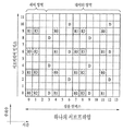
도 9 는 하향링크 ZP (zero-power) CSI-RS 패턴의 일례를 나타낸다. 하나의 기지국은 다른 기지국의 CSI-RS 측정 성능을 향상시키기 위하여 다른 기지국의 CSI-RS 자원 요소에 뮤팅(muting)을 하여 단말이 효율적으로 레이트 매칭(rate matching)을 수행할 수 있도록 한다. 이때, 기지국은 뮤팅된 자원 요소를 ZP CSI-RS 로 설정하여 단말에 알려준다.9 shows an example of a downlink ZP (zero-power) CSI-RS pattern. In order to improve the CSI-RS measurement performance of another base station, one base station performs muting to CSI-RS resource elements of other base stations so that the UE can efficiently perform rate matching. At this time, the base station sets the mutable resource element as ZP CSI-RS and informs the UE.
IMR 은 도 9 에 예시된 것과 같은 ZP CSI-RS 자원 요소의 서브셋(subset)으로 설정된다. 효율적으로 IMR 을 설정하기 위하여 도 10 에 예시된 것과 같은 IMR 호핑(hopping) 패턴을 이용할 수 있다. IMR 호핑 패턴은 다음과 같은 절차에 따라 결정될 수 있다.The IMR is set to a subset of the ZP CSI-RS resource elements as illustrated in FIG. An IMR hopping pattern as illustrated in FIG. 10 may be used to efficiently set the IMR. The IMR hopping pattern can be determined according to the following procedure.
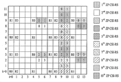
먼저, 도 9 에 예시된 것과 같은 10 개의 ZP CSI-RS 그룹에서 ZP CSI-RS 비트맵(bitmap)으로 두 개의 ZP CSI-RS 그룹을 선택할 수 있다. 선택된 두 개의 ZP CSI-RS 그룹을 제 1 자원 그룹 및 제 2 자원 그룹으로 칭한다. 다음으로, 제 1 자원 그룹에서 4개의 자원 요소 중 2개를 임의로 선택하고, 제2 자원 그룹에서 4개의 자원 요소 중 2 개를 임의로 선택한다. 다음으로, 선택된 4 개의 자원 요소를 하나의 IMR 로 설정한다.First, two ZP CSI-RS groups can be selected as ZP CSI-RS bitmaps in ten ZP CSI-RS groups as illustrated in FIG. The selected two ZP CSI-RS groups are referred to as a first resource group and a second resource group. Next, two of four resource elements are randomly selected in the first resource group, and two of the four resource elements are arbitrarily selected in the second resource group. Next, the selected four resource elements are set to one IMR.
도 10은 상기 절차에 따라 선택된 자원요소, 즉 IMRE-0과 IMRE-1을 나타낸다. IMRE-0는 그룹 0에서 첫 번째 자원 요소와 두 번째 자원 요소를 선택하고, 그룹 1에서 첫 번째 자원 요소와 두 번째 자원 요소를 선택하여 생성되었다. IMRE-1 은 그룹 0 에서 첫 번째 자원 요소와 두 번째 자원 요소를 선택하고, 그룹 1 에서 세 번째 자원 요소와 네 번째 자원 요소를 선택하여 생성되었다.Figure 10 shows selected resource elements, IMRE-0 and IMRE-1, according to the above procedure. IMRE-0 was generated by selecting the first resource element and the second resource element in
IMR 호핑 패턴 설정 방법의 첫 번째 절차에서, 기지국은 단말에게 RRC 와 같은 상위 계층 시그널링을 통해 IMR 이 전송되는 두 개의 그룹을 알려줄 수 있다. 구체적으로 도 10 과 같이 ZP CSI-RS 비트맵을 통해 두 그룹을 지정해 줄 수 있다. 또는 기지국은 단말에게 8 포트 CSI-RS 자원 설정을 통해 두 그룹을 지정해 줄 수 있다. 이 경우 두 그룹의 자원 설정은 항상 8 포트 CSI-RS 자원 설정으로 제한된다. 또한, 단말과 기지국은 서로 공유하는 기 설정된 방법을 이용하여 각 IMR 이 전송되는 두 개의 그룹을 선택할 수 있다.In the first procedure of the IMR hopping pattern setting method, the BS can inform the MS of two groups through which the IMR is transmitted through upper layer signaling such as RRC. Specifically, as shown in FIG. 10, two groups can be designated through a ZP CSI-RS bitmap. Alternatively, the base station can assign two groups to the terminal through the 8-port CSI-RS resource setting. In this case, the resource settings of the two groups are always limited to the setting of the 8-port CSI-RS resource. Also, the UE and the BS can select two groups in which each IMR is transmitted using a predetermined method shared by the UE and the BS.
IMR 호핑 패턴 설정 방법의 두 번째 절차에서, 단말 또는 기지국은 선택된 그룹에서 IMR 자원 요소의 위치를 결정한다. 즉, 첫 번째 절차를 통해 두 개의 그룹이 선택한 이후, 각 그룹에서 2 개의 자원 요소의 위치를 결정한다.In the second procedure of the IMR hopping pattern setting method, the UE or the base station determines the location of the IMR resource element in the selected group. That is, after two groups are selected through the first procedure, the position of two resource elements in each group is determined.
이하에서는, IMR 자원 요소의 위치를 결정하는 IMR 호핑 패턴 결정 방법의 실시예들을 설명한다. 본 발명의 실시예들에 따르면, 기지국과 단말은 PN 코드(code)를 인자로 하는 임의의 함수를 이용하며, 가능한 호핑 패턴의 개수로 모듈러(modular) 연산을 취하여 PN 코드로부터 생성된 난수의 범위(range)를 조절할 수 있다.In the following, embodiments of an IMR hopping pattern determination method for determining the location of an IMR resource element are described. According to embodiments of the present invention, a base station and a terminal use an arbitrary function having a PN code as a factor, take a modular operation as the number of possible hopping patterns, and generate a random number range the range can be adjusted.
제 1 실시예First Embodiment
제 1 실시예는 각 자원 블록에 대해 독립적으로 IMR 호핑 패턴을 결정하는 실시예이다. 즉, 제 1 실시예에 따르면 전체 주파수 밴드를 구성하는 각 자원 블록(RB)에 대해 독립적으로 IMR 호핑 패턴을 결정한다. 구체적으로, 제 1 실시예는 각각의 자원 블록에 대하여 제 1-1, 제 1-2, 및 제 1-3 실시예 중 하나를 이용하여 IMR 호핑 패턴을 결정할 수 있다.The first embodiment is an embodiment for determining the IMR hopping pattern independently for each resource block. That is, according to the first embodiment, the IMR hopping pattern is independently determined for each resource block (RB) constituting the entire frequency band. Specifically, the first embodiment can determine the IMR hopping pattern using one of the 1-1, 1-2, and 1-3 embodiments for each resource block.
제 1-1 실시예Example 1-1 Example
제 1-1 실시예는 각 자원 블록 내에서 하나의 IMR 을 구성하는 두 그룹 각각에 대하여 독립적으로 호핑 패턴을 결정하는 방법이다. 하나의 그룹에서 4 개의 자원 요소 중 2 개를 선택하는 모든 경우의 수는 6 이다. 따라서, 6 가지 경우에 대하여 0 부터 5 까지 인덱싱하고, 특정 함수에 따라 발생된 0 부터 5 사이의 랜덤 숫자를 이용하여 각 그룹에서 2 개의 자원 요소를 결정할 수 있다. 이때, 0 부터 5 사이의 랜덤 숫자를 생성하는 함수의 일례로 아래의 수학식 13 을 이용할 수 있다.The 1-1th embodiment is a method for independently determining a hopping pattern for each of two groups constituting one IMR in each resource block. The number of all cases in which two of four resource elements in a group are selected is six. Therefore, indexing from 0 to 5 for six cases, and using two random numbers between 0 and 5 generated according to a specific function, two resource elements can be determined in each group. At this time, as an example of a function generating a random number between 0 and 5, the following

여기서, i 는 자원 블록 인덱스를 가리키고, c(k)는 PN 코드를 가리키고, ![]()
![]()
단말은 임의의 자원 블록 i 에 대해 수학식 13을 이용하여 IMR의 자원 요소의 위치를 결정할 수 있다. 즉, 2 개의 ZP CSI-RS 자원 그룹 각각에 대해 수학식 13 을 이용하여 IMR 의 자원 요소의 위치를 결정하고, 간섭을 측정할 수 있다.The UE can determine the location of the resource element of the IMR using Equation (13) for an arbitrary resource block i. That is, for each of the two ZP CSI-RS resource groups, the location of the resource element of the IMR can be determined using Equation (13) and the interference can be measured.
마찬가지로, 기지국은 임의의 자원 블록 i 에 대해 수학식 13 을 이용하여 IMR 의 자원 요소의 위치를 결정할 수 있다. 즉, IMR 에 할당된 2 개의 ZP CSI-RS 자원 그룹 각각에 대해 수학식 13 을 이용하여 IMR 자원 요소의 위치를 결정하고, IMR 자원 요소에서 뮤팅을 수행하거나 데이터를 전송할 수 있다.Similarly, the base station can determine the location of the resource element of the IMR using Equation (13) for any resource block i. That is, for each of the two ZP CSI-RS resource groups allocated to the IMR, the location of the IMR resource element can be determined using Equation (13), and muting or data transmission can be performed in the IMR resource element.
단말과 기지국은 호핑 패턴을 동일하게 인덱싱 하기 위해 호핑 패턴과 인덱스를 매핑한 테이블을 공유할 수 있다. 또한, 별도의 공유하는 테이블 없이 정해진 알고리즘에 의해 호핑 패턴을 동일하게 인덱싱할 수도 있다.The terminal and the base station may share a hopping pattern and an index-mapped table in order to index the hopping pattern equally. Also, the hopping pattern may be indexed identically by a predetermined algorithm without a separate shared table.
제 1-2 실시예Example 1-2
제 1-2 실시예는 하나의 IMR 을 구성하는 두 그룹에 대해 상호 종속적으로 호핑 패턴을 결정하는 실시예이다. 즉, 2 개의 ZP CSI-RS 그룹에 대해 각각 수학식 13 을 이용하여 IMR 의 자원 요소 위치를 결정하는 방식 대신, 2개의 그룹에 서로 종속적으로 IMR 의 자원 요소의 위치를 결정할 수 있다.The 1-2 embodiment is an embodiment for mutually determining a hopping pattern mutually depending on two groups constituting one IMR. That is, instead of the method of determining the location of the resource element of the IMR using Equation (13) for each of the two ZP CSI-RS groups, the position of the resource element of the IMR can be determined depending on the two groups.
예를 들면, 단말은 두 그룹 중 첫 번째 그룹의 IMR 자원 요소의 위치는 수학식 13 을 이용하여 실시예 1-1 의 방법으로 결정할 수 있다. 다음으로, 두 번째 그룹의 IMR 자원 요소의 위치를 결정하는 경우, 아래의 수학식 14 와 같이 첫 번째 그룹의 호핑 패턴 인덱스에 오프셋을 더하는 것을 이용하여 자원 요소의 위치를 결정할 수 있다. 이후 단말은 결정된 IMR 로부터 간섭을 측정한다.For example, the UE can determine the position of the IMR resource element of the first group of the two groups by the method of Embodiment 1-1 using Equation (13). Next, when determining the position of the IMR resource element of the second group, the position of the resource element can be determined by adding an offset to the hopping pattern index of the first group as shown in Equation (14). The terminal then measures the interference from the determined IMR.
마찬가지로, 기지국은 수학식 13 을 이용하여 첫 번째 그룹의 IMR 자원 요소의 위치를 결정하고, 수학식 14 를 이용하여 두 번째 그룹의 IMR 자원 요소의 위치를 결정할 수 있다. 이후, 해당 IMR 자원 요소에서 뮤팅을 수행하거나 데이터를 전송할 수 있다.Similarly, the base station may determine the location of the first group of IMR resource elements using Equation (13) and the location of the second group of IMR resource elements using Equation (14). Thereafter, it can perform muting or transmit data in the corresponding IMR resource element.
![]()
![]()
수학식 14 는 호핑 패턴 인덱스에 오프셋을 더한 값을 호핑 패턴 인덱스의 범위 내로 변경하기 위해 모듈러 연산을 이용한다. 또한, 수학식 14 에서 ![]()
![]()
![]()
![]()
![]()
![]()
![]()
![]()
단말과 기지국은 호핑 패턴을 동일하게 인덱싱 하기 위해 호핑 패턴과 인덱스를 매핑한 테이블을 공유할 수 있다. 또한, 별도의 공유하는 테이블 없이 정해진 알고리즘에 의해 호핑패턴을 동일하게 인덱싱할 수도 있다.The terminal and the base station may share a hopping pattern and an index-mapped table in order to index the hopping pattern equally. Also, the hopping pattern may be indexed identically by a predetermined algorithm without a separate shared table.
제 1-3 실시예Examples 1-3
제 1-3 실시예는 하나의 IMR 을 구성하는 두 그룹의 호핑 패턴을 동시에 결정하는 실시예이다. 즉, 상술한 실시예보다 비교적 큰 범위의 난수를 발생시키는 호핑 패턴 생성기를 이용하여 하나의 IMR 을 구성하는 두 그룹의 호핑 패턴을 동시에 결정할 수 있다. 두 그룹에서 각각 2 개의 자원 요소씩 선택하여 4 개의 자원 요소의 IMR 을 결정하는 경우의 수는 총 36 이므로, 단말과 기지국은 아래의 수학식 15 에서 R 값을 36 으로 설정한다.The embodiment 1-3 is an embodiment for simultaneously determining hopping patterns of two groups constituting one IMR. That is, the hopping patterns of two groups constituting one IMR can be determined at the same time by using a hopping pattern generator which generates a relatively large range of random numbers. Since the number of cases in which two resource elements are selected for each of the two groups and the IMR of four resource elements are determined is 36 in total, the terminal and the base station set the R value to 36 in the following Equation (15).
단말은 아래의 수학식 15 를 이용하여 두 그룹에 동시에 적용되는 호핑 패턴 인덱스 P hop(i)를 생성한다. 이후 단말은 호핑 패턴 인덱스로부터 결정된 해당 IMR 자원 요소로부터 간섭을 측정한다.The terminal generates a hopping pattern index P hop ( i ) applied to both groups simultaneously using Equation (15) below. The UE then measures the interference from the corresponding IMR resource element determined from the hopping pattern index.
마찬가지로, 기지국도 아래의 수학식 15 를 이용하여 두 그룹에 동시에 적용되는 호핑 패턴 인덱스 P hop(i)를 생성한다. 이후 기지국은 호핑 패턴 인덱스로부터 결정된 해당 IMR 자원 요소에서 뮤팅을 수행하거나 데이터를 전송한다.Similarly, the base station also generates a hopping pattern index P hop ( i ) applied to both groups simultaneously using Equation (15) below. The base station then performs muting or transmits data in the corresponding IMR resource element determined from the hopping pattern index.

단말과 기지국은 36 개의 호핑 패턴을 동일하게 인덱싱 하기 위해 호핑 패턴과 인덱스를 매핑한 테이블을 공유할 수 있다. 또한, 별도의 공유하는 테이블 없이 정해진 알고리즘에 의해 호핑패턴을 동일하게 인덱싱할 수도 있다.The terminal and the base station can share a hopping pattern and an index-mapped table in order to index 36 hopping patterns equally. Also, the hopping pattern may be indexed identically by a predetermined algorithm without a separate shared table.
초기값은 P hop(-1)=0 으로 설정되거나 RRC 등의 상위 계층 시그널링을 통하여 기지국이 단말로 지정해 줄 수 있다. N 과 0 는 상수이며, N 은 10, O 은 9 로 설정될 수 있다.The initial value may be set to P hop (-1) = 0 or the base station may designate the terminal as an upper layer signaling such as RRC. N and 0 are constants, N can be set to 10, and O can be set to 9.
한편, 제 1 실시예에서 구현 복잡도를 낮추기 위해 단말과 기지국은 P hop(0) 또는 ![]()
![]()
![]()
![]()
![]()
![]()
![]()
![]()
제 2 실시예Second Embodiment
제 2 실시예는 일부 자원 블록이 다른 자원 블록에 종속되도록 IMR 호핑 패턴을 결정하는 실시예이다. 제 1 실시예는 각 자원 블록 i 에 대하여 독립적으로 호핑 패턴을 결정하였으나, 제 2 실시예는 인접 자원 블록을 묶어 호핑 패턴을 결정할 수 있다. 본 명세서에서는 종속적인 IMR 호핑 패턴을 가지도록 하나로 묶여진 자원 블록의 집합을 자원 블록 집합(set)이라 칭한다.The second embodiment is an embodiment in which the IMR hopping pattern is determined such that some resource blocks are dependent on other resource blocks. The first embodiment independently determines the hopping pattern for each resource block i, but the second embodiment can determine the hopping pattern by grouping the neighboring resource blocks. In this specification, a set of resource blocks bundled together to have a dependent IMR hopping pattern is called a resource block set.
제 2-1 실시예Example 2-1
제 2-1 실시예는 하나의 자원 블록 집합을 구성하는 자원 블록에 대해 상호 종속적으로 IMR 호핑 패턴을 결정하는 실시예이다. 즉, 제 1-2 실시예가 하나의 IMR 을 구성하는 두 그룹에 대해 상호 종속적으로 호핑 패턴을 결정하였다면, 제 2-1 실시예는 더욱 확장하여 자원 블록 집합을 구성하는 자원 블록에 대하여 상호 종속적으로 IMR 호핑 패턴을 결정할 수 있다.The embodiment 2-1 is an embodiment in which IMR hopping patterns are determined mutually depending on a resource block constituting one resource block set. That is, if the 1-2 embodiment determines the hopping pattern mutually and subordinate to two groups constituting one IMR, the 2-1 embodiment is further extended so that the resource blocks constituting the set of resource blocks are mutually and inter- The IMR hopping pattern can be determined.
먼저, 단말은 자원 블록 집합 내에서 기준이 되는 하나의 RB (이하, 기준 자원 블록이라 칭함)에 대해 제 1-1 내지 제 1-3 실시예 중 하나를 적용하여 IMR 호핑 패턴을 결정한다.First, the UE determines an IMR hopping pattern by applying one of the 1-1 to 1-3 embodiments to one RB (hereinafter, referred to as a reference resource block) serving as a reference in a resource block set.
이후, 동일한 자원 블록 집합 내의 나머지 자원 블록에 대해 기준 자원 블록을 기준으로 IMR 호핑 패턴을 결정할 수 있다. 기준 자원 블록은 자원 블록 집합 내에 가장 낮은 인덱스를 가지는 자원 블록으로 결정될 수 있다. 기준 자원 블록의 IMR 호핑 패턴이 ![]()
![]()
마찬가지로, 기지국은 기준 자원 블록 i 에 대해 제 1-1 내지 제 1-3 실시예 중 하나를 적용하여 IMR 호핑 패턴을 결정한다. 이후, 기지국은 아래의 수학식 16 또는 17 을 이용하여 동일한 자원 블록 집합에 존재하는 나머지 자원 블록 i 의 IMR 호핑 패턴을 결정한다. 이후 기지국은 해당 IMR 자원 요소에서 뮤팅을 수행하거나 데이터를 전송한다.Similarly, the base station applies one of the 1-1 to 1-3 embodiments to the reference resource block i to determine the IMR hopping pattern. Then, the base station determines the IMR hopping pattern of the remaining resource block i existing in the same resource block set using Equation (16) or (17) below. The base station then performs muting or transmits data in the corresponding IMR resource element.
![]()
![]()
수학식 16 에서 i 는 자원 블록 인덱스를 가리키고, ![]()
![]()
![]()
![]()
수학식 17 에서 i 는 자원 블록 인덱스를 가리키고, P hop 는 기준 자원 블록에서 하나의 IMR 에 대한 호핑 패턴 인덱스를 의미한다. 상수 R 은 가능한 호핑 패턴의 개수를 의미하며 R 은 36 으로 설정한다. Δ(i)는 i 번째 자원 블록에 적용되는 오프셋 값이며, RRC 시그널링 등의 상위 계층 시그널링을 통해 기지국이 단말에게 지정할 수 있다. 간단하게는 Δ(i)=i 로 설정될 수 있다. 즉, 수학식 17 은 하나의 IMR 을 구성하는 두 그룹의 호핑 패턴을 동시에 결정하는 실시예를 나타낸다.In Equation 17, i denotes a resource block index, and P hop denotes a hopping pattern index for one IMR in a reference resource block. The constant R means the number of possible hopping patterns and R is set to 36. ( I ) is an offset value applied to the i-th resource block, and the base station can assign the offset value to the UE through higher layer signaling such as RRC signaling. Can be simply set to? ( I ) = i . That is, Equation (17) represents an embodiment for simultaneously determining hopping patterns of two groups constituting one IMR.
제 2-2 실시예Example 2-2 Example
제 2-2 실시예는 하나의 자원 블록 집합을 구성하는 자원 블록에 대하여 IMR 호핑 패턴을 동시에 결정하는 실시예이다. 즉, 제 2-1 실시예보다 비교적 큰 범위의 난수를 발생시키는 호핑 패턴 생성기를 이용하여 자원 블록 집합을 구성하는 자원 블록의 IMR 호핑 패턴을 동시에 결정할 수 있다.The embodiment 2-2 is an embodiment for simultaneously determining an IMR hopping pattern for a resource block constituting one resource block set. That is, the IMR hopping pattern of a resource block constituting a set of resource blocks can be determined at the same time by using a hopping pattern generator that generates a relatively large range of random numbers.
자원 블록 집합을 구성하는 Y 개의 자원 블록에서 k 번째 그룹의 2 개의 자원 요소를 선택하는 경우의 수는 총 6M이므로, 단말과 기지국은 수학식 13에서 R값을 6M으로 설정하여 자원 블록 집합을 구성하는 Y 개의 자원 블록의 IMR 호핑 패턴을 동시에 결정할 수 있다.From Y resource blocks constituting a resource block set number of case of selecting the two resource elements of the k-th group because it is a total of 6 M, the subscriber station and the base station by setting the R value in the equation (13) with 6 M Set RB And the IMR hopping pattern of the Y resource blocks constituting the resource block.
또는, 제 1-3 실시예와 같이 하나의 IMR 을 구성하는 두 그룹의 IMR 자원 요소를 동시에 결정하는 경우, M 개의 자원 블록에서 4 개의 자원 요소를 선택하는 경우의 수는 총 36M이므로 단말과 기지국은 수학식 15 에서 R 값을 36M으로 설정하여 자원 블록 집합을 구성하는 Y 개 자원 블록의 IMR 호핑 패턴을 동시에 결정할 수 있다.Alternatively, when the IMR resource elements of two groups constituting one IMR are simultaneously determined as in the first to third embodiments, the number of cases in which four resource elements are selected from M resource blocks is 36 M in total, The base station can simultaneously determine the IMR hopping pattern of the Y resource blocks constituting the resource block set by setting the R value to 36 M in Equation (15).
한편, 제 2 실시예에서 구현 복잡도를 낮추기 위해 단말과 기지국은 하나의 자원 블록 집합에 대해 호핑 패턴을 계산 한 뒤, 나머지 자원 블록 집합의 호핑 패턴을 계산된 자원 블록 집합의 호핑 패턴과 동일하게 설정할 수 있다.In order to lower the implementation complexity in the second embodiment, the terminal and the base station calculate a hopping pattern for one resource block set, and set the hopping pattern of the remaining resource block set equal to the hopping pattern of the calculated resource block set .
제 3 실시예Third Embodiment
상술한 제 1 실시예 또는 제 2 실시예에서 IMR 호핑 패턴을 결정할 때, 하나의 그룹에 대해 2 개의 자원 요소를 선택하는 6 가지 조합을 고려하였다. 하지만, 6 가지 조합 중 일부 조합만을 호핑 패턴으로 이용하여 구현 복잡도를 줄일 수 있다.In determining the IMR hopping pattern in the above-described first or second embodiment, six combinations of selecting two resource elements for one group are considered. However, the implementation complexity can be reduced by using only a few combinations of the six combinations as the hopping pattern.
예를 들어, 도 10 에서 하나의 그룹을 구성하는 4 개의 자원 요소 중에서 대각선으로 선택될 수 있는 2 개의 자원 요소를 제외하고, 동일 주파수 또는 동일 OFDM 심볼에 있는 2 개의 자원 요소만을 호핑 패턴으로 결정할 수 있다. 이 경우 단말과 기지국은 하나의 그룹에 대해 4 가지 경우의 호핑 패턴만을 이용하게 된다. 따라서, 상술한 수학식 13, 14, 16 을 그대로 이용하되 R 값을 6 에서 4 로 설정한다. 또한, 상술한 수학식 15, 17 을 그대로 이용하되 R 값을 36 에서 16 으로 설정한다.For example, in FIG. 10, only two resource elements in the same frequency or the same OFDM symbol can be determined as a hopping pattern, except for two resource elements that can be selected diagonally out of the four resource elements constituting one group have. In this case, the terminal and the base station use only four hopping patterns for one group. Therefore, the above equations (13), (14) and (16) are directly used, and the R value is set from 6 to 4. Further, the above equations (15) and (17) are used as they are, and the R value is set from 36 to 16. [
또 다른 예로서, 도 10 에서 하나의 그룹을 구성하는 4 개의 자원 요소 중에서 2 포트 CSI-RS 로 설정 가능한 2 개의 자원 요소만을 호핑 패턴으로 결정할 수 있다. 이 경우 단말과 기지국은 하나의 그룹에 대해 2 가지 호핑 패턴만을 이용하게 된다. 따라서, 상술한 수학식 13, 14, 16 을 그대로 이용하되 R 값을 6 에서 2 로 설정한다. 또한, 상술한 수학식 15, 17 을 그대로 이용하되 R 값을 36 에서 4 로 설정한다.As another example, in FIG. 10, only two resource elements that can be set by the two-port CSI-RS among the four resource elements constituting one group can be determined as a hopping pattern. In this case, the terminal and the base station use only two hopping patterns for one group. Therefore, the above-described equations (13), (14) and (16) are used as they are, and the R value is set to 6 from 2. Further, the above equations (15) and (17) are used as they are, and the R value is set to 36 from 4. [
이하에서는, 본 발명에 따른 의사-랜덤(pseudo-random) 시퀀스 생성기의 초기값 결정 방법을 설명한다.Hereinafter, a method of determining an initial value of a pseudo-random sequence generator according to the present invention will be described.
의사-랜덤 시퀀스 생성기의 두 번째 m-시퀀스의 초기화는 상술한 그룹 인덱스 j, 서빙 셀 식별자(ID) ![]()
![]()
![]()
![]()
![]()
![]()
예를 들면, 의사-랜덤 시퀀스 생성기의 두 번째 m-시퀀스의 초기화는 아래의 수학식 18 에 따라 수행될 수 있다.For example, the initialization of the second m-sequence of the pseudo-random sequence generator may be performed according to
![]()
![]()
수학식 18 에서 서브프레임 숫자n f는 초기화에 관여하지 않으므로 서브프레임 별로 IMR 호핑 패턴은 변하지 않는다.Sub-frame number n f in
또한, 의사-랜덤 시퀀스 생성기의 두 번째 m-시퀀스의 초기화는 아래의 수학식 19 에 따라 수행될 수 있다.In addition, the initialization of the second m-sequence of the pseudo-random sequence generator can be performed according to the following equation (19).
![]()
![]()
수학식 19 는 수학식 18 을 변형하여 서브프레임 숫자n f를 초기화에 변수로 이용하였다. L 은 IMR 호핑의 서브프레임 듀티 사이클(duty cycle)을 결정하는 값으로 L 서브프레임 단위로 IMR 호핑 패턴이 반복된다.
또한, 수학식 19 에서 2 의 지수는 아래의 수학식 20 과 같이 결정될 수도 있다.Further, the exponent of 2 in Equation (19) may be determined as Equation (20) below.
![]()
![]()
또한, 의사-랜덤 시퀀스 생성기의 두 번째 m-시퀀스의 초기화는 아래의 수학식 21 에 따라 수행될 수 있다.In addition, the initialization of the second m-sequence of the pseudo-random sequence generator may be performed according to the following equation (21).
![]()
![]()
수학식 21 은 서빙 셀 식별자 ![]()
![]()
또한, 서빙 셀 식별자 ![]()
![]()
![]()
![]()
![]()
![]()
![]()
![]()
아래의 수학식 25 내지 27 은 상기 수학식 22 내지 24 에서 그룹 인덱스 j, 호핑 파라미터 X, 서브프레임 숫자 n f 를 다른 수식에 넣어 초기화 값을 구한 예이다. 이 때, 수학식 25 와 26 에서 k 는 (X 의 최대값 < 2k)를 만족시키는 최소 정수로 결정된다. 수학식 27 에서 k 는 ((2Y+1)*L 의 최대값 < 2k )를 만족시키는 최소 정수로 결정된다.The following equation (25) to 27 is an example of obtaining the group index j, hopping parameters X, initialization into the sub-frame number n f values in the other formulas in the
![]()
![]()
![]()
![]()
![]()
![]()
예를 들면, 상기 X 는 해당 IMR 이 설정된 CSI 프로세스에 속한 NZP CSI-RS 의 스크램블링 시드(scrambling seed) 값으로 설정될 수 있다. 또는 기지국은 X 를 각 IMR 이 갖는 고유한 값으로 설정하여 단말에게 알려 줄 수 있다. 여기서, 서로 다른 IMR 은 서로 다른 X 값을 갖도록 설정하여 IMR 간 동일 호핑 패턴이 설정되는 것을 방지하고 IMR 충돌(collision)을 최소화 시킬 수 있다.For example, the X may be set to a scrambling seed value of the NZP CSI-RS belonging to the CSI process in which the corresponding IMR is set. Alternatively, the base station may set X to a value unique to each IMR and notify the UE. Here, the different IMRs may be set to have different X values, thereby preventing the same hopping pattern between the IMRs from being set and minimizing the IMR collision.
한편, 상기 수학식 13 및 15 는 각각 보다 간략하게 아래의 수학식 28 및 29 로 변형될 수 있다. 수학식 13 및 15 는 자원 블록 i+1 의 IMR 호핑 패턴을 결정할 때, 자원 블록 i 의 IMR 호핑 패턴에 의사-랜덤 시퀀스의 코드를 더하는 방식을 이용하지만, 수학식 28 및 29 에서 각 자원 블록의 IMR 호핑 패턴은 의사-랜덤 시퀀스의 코드만을 이용하여 결정된다. 상술한 실시예들에서 수학식 13 및 15 에 기반하는 것들은 수학식 13를 수식 28로 대체하거나, 수학식 15를 수학식 29로 대체하여 동일하게 이용할 수 있다. 즉, 수학식 28 에 기반하여 제 1-2 실시예를 적용하는 경우 수학식 14 에서 ![]()
![]()
![]()
![]()


도 11 은 본 발명에 일 실시예에 적용될 수 있는 기지국 및 단말을 예시한다.11 illustrates a base station and a terminal that can be applied to an embodiment of the present invention.
무선 통신 시스템에 릴레이가 포함되는 경우, 백홀 링크에서 통신은 기지국과 릴레이 사이에 이뤄지고 억세스 링크에서 통신은 릴레이와 단말 사이에 이뤄진다. 따라서, 도면에 예시된 기지국 또는 단말은 상황에 맞춰 릴레이로 대체될 수 있다.When a relay is included in a wireless communication system, communication is performed between the base station and the relay on the backhaul link, and communication is performed between the relay and the terminal on the access link. Therefore, the base station or the terminal illustrated in the figure can be replaced with a relay in a situation.
도 11 을 참조하면, 무선 통신 시스템은 기지국(1110) 및 단말(1120)을 포함한다. 기지국(1110)은 프로세서(1113), 메모리(1114) 및 무선 주파수(Radio Frequency, RF) 유닛(1111, 1312)을 포함한다. 프로세서(1113)는 본 발명에서 제안한 절차 및/또는 방법들을 구현하도록 구성될 수 있다. 메모리(1114)는 프로세서(1113)와 연결되고 프로세서(1113)의 동작과 관련한 다양한 정보를 저장한다. RF 유닛(1116)은 프로세서(1113)와 연결되고 무선 신호를 송신 및/또는 수신한다. 단말(1120)은 프로세서(1123), 메모리(1124) 및 RF 유닛(1121, 1322)을 포함한다. 프로세서(1123)는 본 발명에서 제안한 절차 및/또는 방법들을 구현하도록 구성될 수 있다. 메모리(1124)는 프로세서(1123)와 연결되고 프로세서(1123)의 동작과 관련한 다양한 정보를 저장한다. RF 유닛(1121, 1322)은 프로세서(1123)와 연결되고 무선 신호를 송신 및/또는 수신한다. 기지국(1110) 및/또는 단말(1120)은 단일 안테나 또는 다중 안테나를 가질 수 있다. 이상에서 설명된 실시예들은 본 발명의 구성요소들과 특징들이 소정 형태로 결합된 것들이다. 각 구성요소 또는 특징은 별도의 명시적 언급이 없는 한 선택적인 것으로 고려되어야 한다. 각 구성요소 또는 특징은 다른 구성요소나 특징과 결합되지 않은 형태로 실시될 수 있다. 또한, 일부 구성요소들 및/또는 특징들을 결합하여 본 발명의 실시예를 구성하는 것도 가능하다. 본 발명의 실시예들에서 설명되는 동작들의 순서는 변경될 수 있다. 어느 실시예의 일부 구성이나 특징은 다른 실시예에 포함될 수 있고, 또는 다른 실시예의 대응하는 구성 또는 특징과 교체될 수 있다. 특허청구범위에서 명시적인 인용 관계가 있지 않은 청구항들을 결합하여 실시예를 구성하거나 출원 후의 보정에 의해 새로운 청구항으로 포함시킬 수 있음은 자명하다.Referring to FIG. 11, a wireless communication system includes a
본 문서에서 기지국에 의해 수행된다고 설명된 특정 동작은 경우에 따라서는 그 상위 노드(upper node)에 의해 수행될 수 있다. 즉, 기지국을 포함하는 복수의 네트워크 노드들(network nodes)로 이루어지는 네트워크에서 단말과의 통신을 위해 수행되는 다양한 동작들은 기지국 또는 기지국 이외의 다른 네트워크 노드들에 의해 수행될 수 있음은 자명하다. 기지국은 고정국(fixed station), NodeB, eNodeB(eNB), 억세스 포인트(access point) 등의 용어에 의해 대체될 수 있다.The specific operation described herein as being performed by the base station may be performed by its upper node, in some cases. That is, it is apparent that various operations performed for communication with a terminal in a network including a plurality of network nodes including a base station can be performed by a network node other than the base station or the base station. A base station may be replaced by terms such as a fixed station, a Node B, an eNodeB (eNB), an access point, and the like.
본 발명에 따른 실시예는 다양한 수단, 예를 들어, 하드웨어, 펌웨어(firmware), 소프트웨어 또는 그것들의 결합 등에 의해 구현될 수 있다. 하드웨어에 의한 구현의 경우, 본 발명의 일 실시예는 하나 또는 그 이상의 ASICs(application specific integrated circuits), DSPs(digital signal processors), DSPDs(digital signal processing devices), PLDs(programmable logic devices), FPGAs(field programmable gate arrays), 프로세서, 콘트롤러, 마이크로 콘트롤러, 마이크로 프로세서 등에 의해 구현될 수 있다.Embodiments in accordance with the present invention may be implemented by various means, for example, hardware, firmware, software, or a combination thereof. In the case of hardware implementation, an embodiment of the present invention may include one or more application specific integrated circuits (ASICs), digital signal processors (DSPs), digital signal processing devices (DSPDs), programmable logic devices (PLDs) field programmable gate arrays, processors, controllers, microcontrollers, microprocessors, and the like.
펌웨어나 소프트웨어에 의한 구현의 경우, 본 발명의 일 실시예는 이상에서 설명된 기능 또는 동작들을 수행하는 모듈, 절차, 함수 등의 형태로 구현될 수 있다. 소프트웨어 코드는 메모리 유닛에 저장되어 프로세서에 의해 구동될 수 있다.In the case of an implementation by firmware or software, an embodiment of the present invention may be implemented in the form of a module, a procedure, a function, or the like which performs the functions or operations described above. The software code can be stored in a memory unit and driven by the processor.
상기 메모리 유닛은 상기 프로세서 내부 또는 외부에 위치하여, 이미 공지된 다양한 수단에 의해 상기 프로세서와 데이터를 주고 받을 수 있다.The memory unit may be located inside or outside the processor, and may exchange data with the processor by various well-known means.
상술한 바와 같이 개시된 본 발명의 바람직한 실시예들에 대한 상세한 설명은 당업자가 본 발명을 구현하고 실시할 수 있도록 제공되었다. 상기에서는 본 발명의 바람직한 실시예들을 참조하여 설명하였지만, 해당 기술 분야의 숙련된 당업자는 본 발명의 영역으로부터 벗어나지 않는 범위 내에서 본 발명을 다양하게 수정 및 변경시킬 수 있음을 이해할 수 있을 것이다. 예를 들어, 당업자는 상술한 실시예들에 기재된 각 구성을 서로 조합하는 방식으로 이용할 수 있다. 따라서, 본 발명은 여기에 나타난 실시형태들에 제한되려는 것이 아니라, 여기서 개시된 원리들 및 신규한 특징들과 일치하는 최광의 범위를 부여하려는 것이다.DETAILED DESCRIPTION OF THE PREFERRED EMBODIMENTS The foregoing description of the preferred embodiments of the invention disclosed herein has been presented to enable any person skilled in the art to make and use the present invention. While the present invention has been particularly shown and described with reference to preferred embodiments thereof, it will be understood by those skilled in the art that various changes and modifications may be made therein without departing from the spirit and scope of the invention as defined by the appended claims. For example, those skilled in the art can utilize each of the configurations described in the above-described embodiments in a manner of mutually combining them. Accordingly, the present invention is not intended to be limited to the embodiments shown herein but is to be accorded the widest scope consistent with the principles and novel features disclosed herein.
본 발명은 본 발명의 정신 및 필수적 특징을 벗어나지 않는 범위에서 다른 특정한 형태로 구체화될 수 있다. 따라서, 상기의 상세한 설명은 모든 면에서 제한적으로 해석되어서는 아니 되고 예시적인 것으로 고려되어야 한다. 본 발명의 범위는 첨부된 청구항의 합리적 해석에 의해 결정되어야 하고, 본 발명의 등가적 범위 내에서의 모든 변경은 본 발명의 범위에 포함된다. 본 발명은 여기에 나타난 실시형태들에 제한되려는 것이 아니라, 여기서 개시된 원리들 및 신규한 특징들과 일치하는 최광의 범위를 부여하려는 것이다. 또한, 특허청구범위에서 명시적인 인용 관계가 있지 않은 청구항들을 결합하여 실시예를 구성하거나 출원 후의 보정에 의해 새로운 청구항으로 포함할 수 있다.The present invention may be embodied in other specific forms without departing from the spirit or essential characteristics thereof. Accordingly, the above description should not be construed in a limiting sense in all respects and should be considered illustrative. The scope of the present invention should be determined by rational interpretation of the appended claims, and all changes within the scope of equivalents of the present invention are included in the scope of the present invention. The present invention is not intended to be limited to the embodiments shown herein but is to be accorded the widest scope consistent with the principles and novel features disclosed herein. In addition, claims that do not have an explicit citation in the claims may be combined to form an embodiment or be included in a new claim by amendment after the filing.
본 발명은 단말, 릴레이, 기지국 등과 같은 무선 통신 장치에 사용될 수 있다.The present invention can be used in a wireless communication device such as a terminal, a relay, a base station, and the like.
Claims (14)
간섭 측정을 위한 X 개의 영-전력(zero-power) 채널상태정보 참조 신호(CSI-RS)의 자원 요소를 각각 포함하는 제1 자원 그룹 및 제2 자원 그룹을 결정하는 단계;
상기 제1 자원 그룹 및 상기 제2 자원 그룹에서 각각 Y (Y≤X) 개의 자원 요소를 선택하는 단계; 및
상기 선택된 2Y 개의 자원 요소의 위치를 기반으로 인접 기지국의 간섭을 측정하는 단계
를 포함하는, 간섭 측정 방법.A method for measuring interference of a neighboring base station in a wireless communication system,
Determining a first resource group and a second resource group, each of which includes a resource element of X zero-power channel state information reference signal (CSI-RS) for interference measurement;
Selecting Y (Y? X) resource elements in the first resource group and the second resource group, respectively; And
Measuring interference of a neighboring base station based on the positions of the selected 2 Y resource elements
/ RTI >
상기 선택 단계는 의사-랜덤(Pseudo-random) 시퀀스를 이용하여 인덱스를 산출하고, 상기 인덱스에 따라 상기 제1 자원 그룹 및 상기 제2 자원 그룹에서 각각 Y개의 상기 자원 요소를 선택하는, 간섭 측정 방법.The method according to claim 1,
Wherein said selecting step calculates an index using a pseudo-random sequence and selects Y resource elements in each of said first resource group and said second resource group according to said index, .
상기 X는 4이고 Y는 2이며,
상기 선택 단계는 다음 수학식 A를 상기 제1 자원 그룹 및 상기 제2 자원 그룹에 각각 적용하여 상기 인덱스를 산출하는, 간섭 측정 방법.
[수학식 A]

여기서, i는 자원 블록 인덱스이고, j는 자원 그룹 인덱스이고, c(k)는 의사-랜덤 시퀀스이고,
X is 4, Y is 2,
Wherein the selecting step applies the following equation A to the first resource group and the second resource group, respectively, to calculate the index.
[Mathematical formula A]
Where i is a resource block index, j is a resource group index, c ( k ) is a pseudo-random sequence,
상기 X는 4이고 Y는 2이며,
상기 선택 단계는 다음 수학식 A를 상기 제1 자원 그룹에 적용하여 제1 인덱스를 산출하고, 다음 수학식 B를 상기 제2 자원 그룹에 적용하여 제2 인덱스를 산출하는, 간섭 측정 방법.
[수학식 A]

[수학식 B]
여기서, i는 자원 블록 인덱스이고, j는 자원 그룹 인덱스이고, c(k)는 의사-랜덤 시퀀스이고,
X is 4, Y is 2,
Wherein the selecting step calculates a first index by applying the following equation A to the first resource group and applying the following equation B to the second resource group to calculate a second index.
[Mathematical formula A]
[Mathematical expression B]
Where i is a resource block index, j is a resource group index, c ( k ) is a pseudo-random sequence,
상기 X는 4이고 Y는 2이며,
상기 선택 단계는 다음 수학식 C를 상기 제1 자원 그룹 및 상기 제2 자원 그룹에 적용하여 상기 인덱스를 산출하는, 간섭 측정 방법.
[수학식 C]

여기서, i는 자원 블록 인덱스이고, j는 자원 그룹 인덱스이고, c(k)는 의사-랜덤 시퀀스이고,
X is 4, Y is 2,
Wherein the selecting step applies the following equation (C) to the first resource group and the second resource group to calculate the index.
[Mathematical expression C]
Where i is a resource block index, j is a resource group index, c ( k ) is a pseudo-random sequence,
상기 선택된 4개의 자원 요소를 포함하는 자원 블록에 연관된 종속 자원 블록에 대하여 다음 수학식 D를 적용하여 4개의 자원 요소를 선택하는 단계를 더 포함하는, 간섭 측정 방법.
[수학식 D]
여기서, i는 자원 블록 인덱스이고, j는 자원 그룹 인덱스이고, mod는 모듈러 연산이고, R는 6이고, Δ(i)는 i 번째 자원 블록에 적용되는 오프셋 값이다.The method of claim 3,
Further comprising selecting four resource elements by applying the following equation (D) to a dependent resource block associated with a resource block including the selected four resource elements.
[Mathematical expression D]
Here, i is a resource block index, j is a resource group index, mod is a modular operation, R is 6, and? ( I ) is an offset value applied to the ith resource block.
상기 선택된 4개의 자원 요소를 포함하는 자원 블록에 연관된 종속 자원 블록에 대하여 다음 수학식 E를 적용하여 4개의 자원 요소를 선택하는 단계를 더 포함하는, 간섭 측정 방법.
[수학식 E]

여기서, i는 자원 블록 인덱스이고, j는 자원 그룹 인덱스이고, c(k)는 의사-랜덤 시퀀스이고,
Further comprising selecting four resource elements by applying Equation (E) to a dependent resource block associated with a resource block including the selected four resource elements.
(E)
Where i is a resource block index, j is a resource group index, c ( k ) is a pseudo-random sequence,
간섭 측정을 위한 X 개의 영-전력(zero-power) 채널상태정보 참조 신호(CSI-RS)의 자원 요소를 각각 포함하는 제1 자원 그룹 및 제2 자원 그룹을 결정하는 단계;
상기 제1 자원 그룹 및 상기 제2 자원 그룹에서 각각 Y (Y≤X) 개의 자원 요소를 선택하는 단계; 및
상기 선택된 2Y 개의 자원 요소에서 뮤팅(muting)을 수행하는 단계
를 포함하는, 간섭 측정 지원 방법.A method in a base station supporting interference measurements in a wireless communication system,
Determining a first resource group and a second resource group, each of which includes a resource element of X zero-power channel state information reference signal (CSI-RS) for interference measurement;
Selecting Y (Y? X) resource elements in the first resource group and the second resource group, respectively; And
Performing muting in the selected 2 Y resource elements
/ RTI >
상기 선택 단계는 의사-랜덤(Pseudo-random) 시퀀스를 이용하여 인덱스를 산출하고, 상기 인덱스에 따라 상기 제1 자원 그룹 및 상기 제2 자원 그룹에서 각각 Y개의 상기 자원 요소를 선택하는, 간섭 측정 지원 방법.9. The method of claim 8,
Wherein the selecting step calculates an index using a pseudo-random sequence and selects Y resource elements in each of the first resource group and the second resource group according to the index, Way.
상기 X는 4이고 Y는 2이며,
상기 선택 단계는 다음 수학식 A를 상기 제1 자원 그룹 및 상기 제2 자원 그룹에 각각 적용하여 상기 인덱스를 산출하는, 간섭 측정 지원 방법.
[수학식 A]

여기서, i는 자원 블록 인덱스이고, j는 자원 그룹 인덱스이고, c(k)는 의사-랜덤 시퀀스이고,
X is 4, Y is 2,
Wherein the selecting step applies the following equation A to the first resource group and the second resource group, respectively, to calculate the index.
[Mathematical formula A]
Where i is a resource block index, j is a resource group index, c ( k ) is a pseudo-random sequence,
상기 X는 4이고 Y는 2이며,
상기 선택 단계는 다음 수학식 A를 상기 제1 자원 그룹에 적용하여 제1 인덱스를 산출하고, 다음 수학식 B를 상기 제2 자원 그룹에 적용하여 제2 인덱스를 산출하는, 간섭 측정 지원 방법.
[수학식 A]
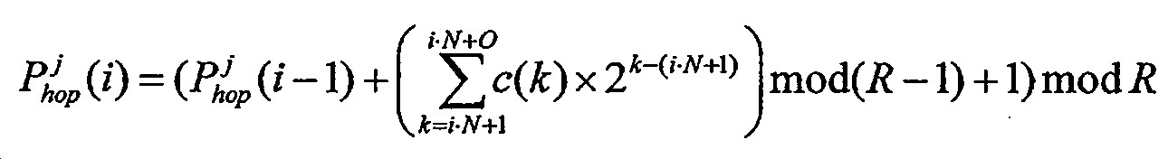
[수학식 B]
여기서, i는 자원 블록 인덱스이고, j는 자원 그룹 인덱스이고, c(k)는 의사-랜덤 시퀀스이고,
X is 4, Y is 2,
Wherein the selecting step calculates a first index by applying the following equation A to the first resource group and applying a following equation B to the second resource group to calculate a second index.
[Mathematical formula A]
[Mathematical expression B]
Where i is a resource block index, j is a resource group index, c ( k ) is a pseudo-random sequence,
상기 X는 4이고 Y는 2이며,
상기 선택 단계는 다음 수학식 C를 상기 제1 자원 그룹 및 상기 제2 자원 그룹에 적용하여 상기 인덱스를 산출하는, 간섭 측정 지원 방법.
[수학식 C]

여기서, i는 자원 블록 인덱스이고, j는 자원 그룹 인덱스이고, c(k)는 의사-랜덤 시퀀스이고,
X is 4, Y is 2,
Wherein the selecting step applies the following equation (C) to the first resource group and the second resource group to calculate the index.
[Mathematical expression C]
Where i is a resource block index, j is a resource group index, c ( k ) is a pseudo-random sequence,
상기 선택된 4개의 자원 요소를 포함하는 자원 블록에 연관된 종속 자원 블록에 대하여 다음 수학식 D를 적용하여 4개의 자원 요소를 선택하는 단계를 더 포함하는, 간섭 측정 지원 방법.
[수학식 D]
여기서, i는 자원 블록 인덱스이고, j는 자원 그룹 인덱스이고, mod는 모듈러 연산이고, R는 6이고, Δ(i)는 i 번째 자원 블록에 적용되는 오프셋 값이다.11. The method of claim 10,
Further comprising selecting four resource elements by applying Equation (D) to a dependent resource block associated with a resource block including the selected four resource elements.
[Mathematical expression D]
Here, i is a resource block index, j is a resource group index, mod is a modular operation, R is 6, and? ( I ) is an offset value applied to the ith resource block.
상기 선택된 4개의 자원 요소를 포함하는 자원 블록에 연관된 종속 자원 블록에 대하여 다음 수학식 E를 적용하여 4개의 자원 요소를 선택하는 단계를 더 포함하는, 간섭 측정 지원 방법.
[수학식 E]

여기서, i는 자원 블록 인덱스이고, j는 자원 그룹 인덱스이고, c(k)는 의사-랜덤 시퀀스이고,
Further comprising selecting four resource elements by applying Equation (E) to a dependent resource block associated with a resource block including the selected four resource elements.
(E)
Where i is a resource block index, j is a resource group index, c ( k ) is a pseudo-random sequence,
Applications Claiming Priority (3)
| Application Number | Priority Date | Filing Date | Title |
|---|---|---|---|
| US201261696784P | 2012-09-04 | 2012-09-04 | |
| US61/696,784 | 2012-09-04 | ||
| PCT/KR2013/007971 WO2014038842A1 (en) | 2012-09-04 | 2013-09-04 | Method for measuring interference of neighboring base station in wireless communication system and method for supporting interference measurement |
Publications (2)
| Publication Number | Publication Date |
|---|---|
| KR20150068376A KR20150068376A (en) | 2015-06-19 |
| KR101615242B1 true KR101615242B1 (en) | 2016-04-25 |
Family
ID=50237392
Family Applications (1)
| Application Number | Title | Priority Date | Filing Date |
|---|---|---|---|
| KR1020157008762A Expired - Fee Related KR101615242B1 (en) | 2012-09-04 | 2013-09-04 | Method for measuring interference of neighboring base station in wireless communication system and method for supporting interference measurement |
Country Status (3)
| Country | Link |
|---|---|
| US (1) | US9794813B2 (en) |
| KR (1) | KR101615242B1 (en) |
| WO (1) | WO2014038842A1 (en) |
Families Citing this family (5)
| Publication number | Priority date | Publication date | Assignee | Title |
|---|---|---|---|---|
| WO2017105005A1 (en) * | 2015-12-18 | 2017-06-22 | 엘지전자 주식회사 | Method and wireless device for transmitting random-access preamble by means of single-tone method |
| US20180062801A1 (en) * | 2016-08-24 | 2018-03-01 | Qualcomm Incorporated | Techniques for wireless communications in coordinated multi-point operation |
| US11985653B2 (en) | 2019-05-07 | 2024-05-14 | Samsung Electronics Co., Ltd. | Apparatus and method for controlling interference between base stations in wireless communications system |
| WO2021185119A1 (en) * | 2020-03-17 | 2021-09-23 | 上海朗帛通信技术有限公司 | Method and apparatus used in wireless communication node |
| KR20250001762A (en) | 2023-06-29 | 2025-01-07 | 주식회사 케이티 | Method for configuring resource element allocated to CSI-RS port numbers for CSI-RS transmission of a base station and base station using the same |
Citations (1)
| Publication number | Priority date | Publication date | Assignee | Title |
|---|---|---|---|---|
| US20120213261A1 (en) | 2011-02-21 | 2012-08-23 | Motorola Mobility, Inc. | Method and apparatus for reference signal processing in an orthogonal frequency division multiplexing communication system |
Family Cites Families (9)
| Publication number | Priority date | Publication date | Assignee | Title |
|---|---|---|---|---|
| US9374131B2 (en) * | 2009-01-28 | 2016-06-21 | Qualcomm Incorporated | Frequency hopping in a wireless communication network |
| KR101568696B1 (en) | 2009-04-09 | 2015-11-12 | 세종대학교산학협력단 | Wireless communication scheduling control system and method thereof |
| KR101819502B1 (en) * | 2010-02-23 | 2018-01-17 | 엘지전자 주식회사 | A method and a user equipment for measuring interference, and a method and a base station for receiving interference information |
| CN102300320B (en) | 2010-06-22 | 2014-04-30 | 上海贝尔股份有限公司 | Inter-cell interference coordination method and device |
| US8675560B2 (en) | 2010-09-03 | 2014-03-18 | Qualcomm Incorporated | UE receiver reference signal processing that utilizes resource partitioning information |
| US8576742B2 (en) * | 2010-10-06 | 2013-11-05 | Qualcomm Incorporated | Dynamic switching between common reference signal interference cancellation and resource element puncturing in a co-channel heterogeneous network |
| CN103733676B (en) * | 2011-08-12 | 2018-01-05 | 交互数字专利控股公司 | Interference Measurements in Wireless Networks |
| US9106386B2 (en) * | 2012-08-03 | 2015-08-11 | Intel Corporation | Reference signal configuration for coordinated multipoint |
| US10159052B2 (en) * | 2012-08-03 | 2018-12-18 | Qualcomm Incorporated | Method and apparatus for sounding reference signal triggering and power control for coordinated multi-point operations |
-
2013
- 2013-09-04 WO PCT/KR2013/007971 patent/WO2014038842A1/en not_active Ceased
- 2013-09-04 US US14/426,077 patent/US9794813B2/en not_active Expired - Fee Related
- 2013-09-04 KR KR1020157008762A patent/KR101615242B1/en not_active Expired - Fee Related
Patent Citations (1)
| Publication number | Priority date | Publication date | Assignee | Title |
|---|---|---|---|---|
| US20120213261A1 (en) | 2011-02-21 | 2012-08-23 | Motorola Mobility, Inc. | Method and apparatus for reference signal processing in an orthogonal frequency division multiplexing communication system |
Also Published As
| Publication number | Publication date |
|---|---|
| WO2014038842A1 (en) | 2014-03-13 |
| US20150223086A1 (en) | 2015-08-06 |
| KR20150068376A (en) | 2015-06-19 |
| US9794813B2 (en) | 2017-10-17 |
Similar Documents
| Publication | Publication Date | Title |
|---|---|---|
| US11368858B2 (en) | Method and apparatus for feeding back aggregated channel state information in cooperative multipoint communication system | |
| KR101662088B1 (en) | Method and device for transmitting channel state information in wireless communication system | |
| CN109923828B (en) | Method for detecting terminal in wireless communication system and apparatus for the same | |
| KR101925032B1 (en) | Method and apparatus for estimating channel in wireless communication system | |
| KR101741554B1 (en) | Method and apparatus for transceiving channel status information in wireless communication system supporting cooperative transmission | |
| KR101835328B1 (en) | Method and apparatus for providing channel state information-reference signal (csi-rs) configuration information in a wireless communication system supporting multiple antennas | |
| EP2874335B1 (en) | Method and device for reporting channel state information in wireless communication system | |
| KR102014797B1 (en) | Method and apparatus for transmitting channel state information in wireless access system | |
| KR101979852B1 (en) | Method and device for transmitting channel state information in wireless communication system | |
| KR101594377B1 (en) | Channel estimation method and apparatus using reference signal | |
| KR20190028796A (en) | Method and apparatus for uplink transmission and reception in a wireless communication system | |
| KR20140038546A (en) | Method and apparatus for monitoring a wireless link in a wireless communication system | |
| KR101868629B1 (en) | Method and apparatus for removing interference signal in wireless communication system | |
| KR101615242B1 (en) | Method for measuring interference of neighboring base station in wireless communication system and method for supporting interference measurement | |
| KR20130106260A (en) | Apparatus and method for receiving signal in wireless communication system supporting mu-mimo | |
| KR20170084038A (en) | Method and apparatus for receiving signals in a wireless access system supporting FDR transmission |
Legal Events
| Date | Code | Title | Description |
|---|---|---|---|
| A201 | Request for examination | ||
| PA0105 | International application |
St.27 status event code: A-0-1-A10-A15-nap-PA0105 |
|
| PA0201 | Request for examination |
St.27 status event code: A-1-2-D10-D11-exm-PA0201 |
|
| PN2301 | Change of applicant |
St.27 status event code: A-3-3-R10-R13-asn-PN2301 St.27 status event code: A-3-3-R10-R11-asn-PN2301 |
|
| PG1501 | Laying open of application |
St.27 status event code: A-1-1-Q10-Q12-nap-PG1501 |
|
| D13-X000 | Search requested |
St.27 status event code: A-1-2-D10-D13-srh-X000 |
|
| D14-X000 | Search report completed |
St.27 status event code: A-1-2-D10-D14-srh-X000 |
|
| E701 | Decision to grant or registration of patent right | ||
| PE0701 | Decision of registration |
St.27 status event code: A-1-2-D10-D22-exm-PE0701 |
|
| GRNT | Written decision to grant | ||
| PR0701 | Registration of establishment |
St.27 status event code: A-2-4-F10-F11-exm-PR0701 |
|
| PR1002 | Payment of registration fee |
St.27 status event code: A-2-2-U10-U12-oth-PR1002 Fee payment year number: 1 |
|
| PG1601 | Publication of registration |
St.27 status event code: A-4-4-Q10-Q13-nap-PG1601 |
|
| P22-X000 | Classification modified |
St.27 status event code: A-4-4-P10-P22-nap-X000 |
|
| FPAY | Annual fee payment |
Payment date: 20190314 Year of fee payment: 4 |
|
| PR1001 | Payment of annual fee |
St.27 status event code: A-4-4-U10-U11-oth-PR1001 Fee payment year number: 4 |
|
| PC1903 | Unpaid annual fee |
St.27 status event code: A-4-4-U10-U13-oth-PC1903 Not in force date: 20200420 Payment event data comment text: Termination Category : DEFAULT_OF_REGISTRATION_FEE |
|
| PN2301 | Change of applicant |
St.27 status event code: A-5-5-R10-R13-asn-PN2301 St.27 status event code: A-5-5-R10-R11-asn-PN2301 |
|
| PC1903 | Unpaid annual fee |
St.27 status event code: N-4-6-H10-H13-oth-PC1903 Ip right cessation event data comment text: Termination Category : DEFAULT_OF_REGISTRATION_FEE Not in force date: 20200420 |