KR20150126996A - A milling tool and a tool body - Google Patents
A milling tool and a tool body Download PDFInfo
- Publication number
- KR20150126996A KR20150126996A KR1020150062237A KR20150062237A KR20150126996A KR 20150126996 A KR20150126996 A KR 20150126996A KR 1020150062237 A KR1020150062237 A KR 1020150062237A KR 20150062237 A KR20150062237 A KR 20150062237A KR 20150126996 A KR20150126996 A KR 20150126996A
- Authority
- KR
- South Korea
- Prior art keywords
- along
- cutting
- helix
- radial distance
- spiral
- Prior art date
- Legal status (The legal status is an assumption and is not a legal conclusion. Google has not performed a legal analysis and makes no representation as to the accuracy of the status listed.)
- Withdrawn
Links
- 238000003801 milling Methods 0.000 title claims abstract description 109
- 230000002093 peripheral effect Effects 0.000 claims abstract description 21
- 230000036346 tooth eruption Effects 0.000 claims abstract description 18
- 238000000034 method Methods 0.000 claims description 15
- 238000000926 separation method Methods 0.000 claims description 6
- 238000003754 machining Methods 0.000 description 16
- 239000000463 material Substances 0.000 description 5
- 230000001788 irregular Effects 0.000 description 4
- 238000009434 installation Methods 0.000 description 3
- 229910000997 High-speed steel Inorganic materials 0.000 description 2
- 238000012886 linear function Methods 0.000 description 2
- 238000007493 shaping process Methods 0.000 description 2
- 230000003247 decreasing effect Effects 0.000 description 1
- 230000000694 effects Effects 0.000 description 1
- 238000003825 pressing Methods 0.000 description 1
- 239000007787 solid Substances 0.000 description 1
Images




Classifications
-
- B—PERFORMING OPERATIONS; TRANSPORTING
- B23—MACHINE TOOLS; METAL-WORKING NOT OTHERWISE PROVIDED FOR
- B23F—MAKING GEARS OR TOOTHED RACKS
- B23F21/00—Tools specially adapted for use in machines for manufacturing gear teeth
- B23F21/12—Milling tools
- B23F21/122—Milling tools having a shape similar to that of a gear or part thereof, with cutting edges situated on the tooth contour lines
-
- B—PERFORMING OPERATIONS; TRANSPORTING
- B23—MACHINE TOOLS; METAL-WORKING NOT OTHERWISE PROVIDED FOR
- B23F—MAKING GEARS OR TOOTHED RACKS
- B23F21/00—Tools specially adapted for use in machines for manufacturing gear teeth
- B23F21/12—Milling tools
- B23F21/16—Hobs
- B23F21/163—Hobs with inserted cutting elements
- B23F21/166—Hobs with inserted cutting elements in exchangeable arrangement
-
- B—PERFORMING OPERATIONS; TRANSPORTING
- B23—MACHINE TOOLS; METAL-WORKING NOT OTHERWISE PROVIDED FOR
- B23C—MILLING
- B23C5/00—Milling-cutters
- B23C5/02—Milling-cutters characterised by the shape of the cutter
- B23C5/12—Cutters specially designed for producing particular profiles
-
- B—PERFORMING OPERATIONS; TRANSPORTING
- B23—MACHINE TOOLS; METAL-WORKING NOT OTHERWISE PROVIDED FOR
- B23F—MAKING GEARS OR TOOTHED RACKS
- B23F1/00—Making gear teeth by tools of which the profile matches the profile of the required surface
- B23F1/06—Making gear teeth by tools of which the profile matches the profile of the required surface by milling
-
- B—PERFORMING OPERATIONS; TRANSPORTING
- B23—MACHINE TOOLS; METAL-WORKING NOT OTHERWISE PROVIDED FOR
- B23F—MAKING GEARS OR TOOTHED RACKS
- B23F21/00—Tools specially adapted for use in machines for manufacturing gear teeth
- B23F21/12—Milling tools
- B23F21/126—Milling tools with inserted cutting elements
- B23F21/128—Milling tools with inserted cutting elements in exchangeable arrangement
-
- Y—GENERAL TAGGING OF NEW TECHNOLOGICAL DEVELOPMENTS; GENERAL TAGGING OF CROSS-SECTIONAL TECHNOLOGIES SPANNING OVER SEVERAL SECTIONS OF THE IPC; TECHNICAL SUBJECTS COVERED BY FORMER USPC CROSS-REFERENCE ART COLLECTIONS [XRACs] AND DIGESTS
- Y10—TECHNICAL SUBJECTS COVERED BY FORMER USPC
- Y10T—TECHNICAL SUBJECTS COVERED BY FORMER US CLASSIFICATION
- Y10T407/00—Cutters, for shaping
- Y10T407/17—Gear cutting tool
- Y10T407/1715—Hob
-
- Y—GENERAL TAGGING OF NEW TECHNOLOGICAL DEVELOPMENTS; GENERAL TAGGING OF CROSS-SECTIONAL TECHNOLOGIES SPANNING OVER SEVERAL SECTIONS OF THE IPC; TECHNICAL SUBJECTS COVERED BY FORMER USPC CROSS-REFERENCE ART COLLECTIONS [XRACs] AND DIGESTS
- Y10—TECHNICAL SUBJECTS COVERED BY FORMER USPC
- Y10T—TECHNICAL SUBJECTS COVERED BY FORMER US CLASSIFICATION
- Y10T407/00—Cutters, for shaping
- Y10T407/17—Gear cutting tool
- Y10T407/1715—Hob
- Y10T407/1725—Hob including holder having seat for inserted tool
Landscapes
- Engineering & Computer Science (AREA)
- Mechanical Engineering (AREA)
- Gear Processing (AREA)
- Milling Processes (AREA)
Abstract
원통형 톱니들을 구비하는 작업편의 호브 절삭을 위한 밀링 공구는, 그들 사이에서 중앙 회전 축선이 연장하는 두 개의 대향 단부들 및 주변 표면을 구비하는 공구 보디, 및 주변 표면으로부터 돌출하는 다수의 절삭 치형부들을 포함하고, 상기 절삭 치형부들 (8a ~ 8h) 의 전방 단부 세트는 중앙 회전 축선과 동심인 가상 나선의 전방 단부 부분을 따라서 배치되고, 상기 절삭 치형부들 (8i) 의 후방 단부 세트는 상기 나선의 후방 단부 부분을 따라서 배치된다. 절삭 치형부들은 전방 단부 세트의 최전방 절삭 치형부 (8a) 로 시작하여 작업편과 연속적으로 맞물리도록 배치된다. 후방 단부 세트는 중앙 회전 축선으로부터 일정한 제 1 방사상 거리 (r1) 에 배치된 적어도 세 개의 인접한 절삭 치형부들을 구비한다. 전방 단부 세트는 중앙 회전 축선으로부터 나선을 따라서 일정하지 않은 제 2 방사상 거리 (r2) 에 배치된 적어도 두 개의 인접한 절삭 치형부들을 구비한다. 제 2 방사상 거리는 제 1 방사상 거리보다 더 작고 최전방 절삭 치형부로부터 나선을 따라서 연속적으로 증가한다.A milling tool for hob cutting comprises a tool body having two opposite ends and a peripheral surface between which a central axis of rotation extends, and a plurality of cutting teeth protruding from the peripheral surface , Wherein a set of front ends of the cut tooth portions (8a-8h) are arranged along a forward end portion of a virtual helix concentric with the central axis of rotation, the set of rear ends of the cut tooth portions (8i) Is disposed along the end portion. The toothed portions start with the forefront cutting tooth 8a of the front end set and are arranged to engage successively with the workpiece. The rear end set has at least three adjacent tooth teeth disposed at a constant first radial distance r1 from the central axis of rotation. The front end set includes at least two adjacent tooth teeth disposed at a second radial distance r2 that is not constant along the spiral from the central axis of rotation. The second radial distance is smaller than the first radial distance and increases continuously along the helix from the forefront cutting tooth.
Description
본 발명은 기어 휠들 등의 원통형 톱니들을 구비하거나 랙들을 구비하는 작업편의 호브 절삭 (hobbing) 을 위해 형성된 밀링 공구에 관한 것이다. 또한, 본 발명은 이러한 밀링 공구용 공구 보디 및 이러한 공구 보디용 세그먼트에 관한 것이다.The present invention relates to a milling tool formed for hobbing a workpiece with racks or with cylindrical teeth such as gear wheels. The present invention also relates to such tool bodies for milling tools and segments for such tool bodies.
밀링 공구는 양자의 스퍼들, 즉 직선의 원통형 기어들의 형태로 또는 나선형 우선 (right hand; 右旋) 기어 또는 나선형 좌선 (left hand; 左旋) 기어의 형태로 원통형 톱니들을 형성하기 위해 구성될 수도 있다. 이러한 목적을 위해 밀링 공구는 양자의 우선 리드 (lead) 또는 좌선 리드으로 구성될 수도 있다.The milling tool may be configured to form cylindrical spurs in the form of both spurs, i.e., linear cylindrical gears, or in the form of a right hand gear or a spiral left hand gear . For this purpose, the milling tool may consist of both a first lead or a left lead.
작업편의 호브 절삭을 위해 형성된 밀링 공구들은 EP2487000, EP2662173, 및 EP2537617 에서 개시된다.Milling tools formed for workpiece hob cutting are disclosed in EP2487000, EP2662173, and EP2537617.
EP2487000 는 기어 휠들 등의 원통형 톱니들을 구비하거나 랙들을 구비하는 작업편의 호브 절삭을 위해 형성된 밀링 공구를 개시한다. 밀링 공구는, 주변 표면과 두 개의 대향 단부들을 구비하는 공구 보디를 포함하고, 상기 두 개의 대향 단부들 사이에서 중앙 회전 축선이 연장하고, 상기 공구 보디는 중앙 회전 축선을 중심으로 미리 정해진 회전 방향으로 회전가능하다. 공구는 주변 표면으로부터 돌출하는 절삭 인서트들의 형태로 다수의 이격된 절삭 치형부들을 추가로 포함하고, 각각의 절식 치형부는 절삭 날 및 칩 표면을 포함한다. 절삭 치형부들은 나선을 따라서 작업편에 연속적으로 맞물리기 위하여 중앙 회전 축선과 동심인 가상 나선을 따라서 배치된다. 절삭 치형부들은 중앙 회전 축선으로부터 동일한 방사상 거리에 모두 배치된다.EP 2487000 discloses a milling tool formed for hob cutting of work pieces with cylindrical teeth or gears, such as gear wheels. A milling tool comprising a tool body having a peripheral surface and two opposing ends, a central axis of rotation extending between the two opposite ends, the tool body having a predetermined rotational direction about a central axis of rotation It is rotatable. The tool further comprises a plurality of spaced apart teeth in the form of cutting inserts projecting from the peripheral surface, each of the teeth comprising a cutting edge and a chip surface. The toothed portions are arranged along a virtual helix concentric with the central axis of rotation to continuously engage the workpiece along the helix. The toothed portions are all located at the same radial distance from the central axis of rotation.
EP2487000 에 개시된 밀링 공구는, 공구 길이가 작업편의 코드 (chord) 를 커버하기에 충분히 길어질 필요가 있어서 공구의 절삭 치형부들이 공구와의 맞물림에 대한 작업편 롤들로서 작업편과 부드럽게 맞물릴 수 있는 일종의 밀링 공구이다. 특히 황삭에 대한 이러한 전제 조건의 충족 실패는 작업편과의 맞물림 시에 최전방 절삭 치형부들에 큰 힘이 가해지는 것을 야기한다. 그러므로, 비교적 짧은 공구들은 높은 소음 레벨들과 관련된다. 작업편과 동시에 맞물린 수개의 절삭 치형부들을 구비하는 긴 공구들은 더 낮은 소음 레벨들과 관련되지만, 다른 한편으로는 진동하기 쉬워 진다. 게다가, 큰 재료 비용들로 인해 그리고 큰 서비스 비용들로 인해 예컨대 마모된 절삭 인서트들을 교제하기 위하여, 또는 공구가 고체의 고속 스틸 공구인 경우 절삭 날들을 샤프닝 (sharpening) 하기 위하여 이러한 긴 공구들과 관련된 비용들이 높아 진다. 공구의 절삭 치형부들에 대한 불규칙적인 마모로부터 높은 서비스 비용들이 뒤따른다. 나선의 최전방 및 최후방 턴들의 절삭 치형부들은 공구의 중앙 섹션에 위치된 절삭 치형부들보다 더 적은 재료를 제거하고, 따라서 마모에 덜 민감하다. 마모된 절삭 인서트들의 교체 시에, 많은 수의 인서트들이 마모에 대해 검사될 필요가 있고, 또한 그러하지 않은 인서트들은 교체될 필요가 있다. 게다가, 기계 가공 동안 절삭 치형부들에 가해진 힘들이 더 큰 중앙 섹션이 단부 섹션들보다 더 빨리 마모되기 때문에, 공구 보디에 대한 마모는 불규칙하다. 이러한 이유를 위하여, 값비싼 공구 보디는 종종 단부 섹션들이 여전히 작동될지라도 중앙 섹션에 대한 마모로 인해 교체될 필요가 있다.The milling tool disclosed in EP 2487000 requires that the tool length be long enough to cover the workpiece chord so that the tool teeth of the tool are a kind of workpiece rolls which can be gently engaged with the workpiece as the workpiece rolls for engagement with the tool It is a milling tool. Failure to meet these preconditions, especially for roughing, causes a great amount of force to be applied to the foremost cutting teeth when engaged with the workpiece. Therefore, relatively short tools are associated with high noise levels. Long tools with several cutting teeth engaged simultaneously with the workpiece are associated with lower noise levels, but on the other hand they tend to oscillate. In addition, due to the large material costs and the large service costs associated with such long tools, for example in order to associate worn cutting inserts or to sharpen cutting edges when the tool is a solid high speed steel tool Costs increase. High service costs are followed by irregular wear on the toothed portions of the tool. The cutter teeth of the forward and reverse turns of the helix remove less material than the cutter teeth located in the center section of the tool and are therefore less susceptible to wear. Upon replacement of the worn cutting inserts, a large number of inserts need to be inspected for wear, and such inserts need to be replaced. In addition, wear on the tool body is irregular since forces applied to the toothed portions during machining cause the larger center section to wear faster than the end sections. For this reason, expensive tool bodies often need to be replaced due to wear to the center section, even though the end sections are still actuated.
EP2662173 및 EP2537617 는 수개의 분리가능하게 상호 연결된 디스크 형상의 세그먼트들로부터 형성된 공구 보디를 포함하는 호브 절삭용 밀링 공구들을 개시하고, 각각의 세그먼트는 다수의 절삭 치형부들을 포함한다. 이러한 공구들을 이용하여, 공구 보디의 마모된 섹션들만 교체하는 것이 가능하고, 따라서 밀링 공구의 부품들의 수명을 연장하는 것이 가능하다. 하지만, 공구 또는 심지어 세그먼트 내의 절삭 치형부들에 대한 불규칙적인 마모가 갖는 문제는 계속된다. EP2662173 및 EP2537617 에 개시된 종류의 짧은 밀링 공구들은 특히 작업편의 황삭에 대해 전술한 단점과 관련된다.EP2662173 and EP2537617 disclose milling tools for hob cutting comprising a tool body formed from several detachably interconnected disc shaped segments, each segment comprising a plurality of cut teeth. With these tools, it is possible to replace only the worn sections of the tool body, thus extending the life of the parts of the milling tool. However, the problem of irregular wear on the tool or even the toothed portions in the segment continues. Short milling tools of the kind disclosed in EP 2662173 and EP 2537617 relate to the abovementioned disadvantages, in particular with regard to the roughing of the workpiece.
본 발명은 전술한 문제점들을 극복하는 것과 작업편의 호브 절삭에 적합한 밀링 공구를 제공하는 것을 목표로 하고, 상기 밀링 공구는 불규칙적인 마모에 덜 민감하며, 이는 짧은 밀링 공구의 이점들을 긴 밀링 공구의 이점들 (예컨대, 더 낮은 소음) 과 결합시킨다. 그러므로, 본 발명의 주된 목적은 호브 절삭용 밀링 공구 및 이러한 밀링 공구용의 공구 보디를 제공하는 것이고, 이들은 호브 절삭을 위해 공지된 밀링 공구들 및 공구 보디들에 대하여 적어도 일부 개선된 양태로 존재한다. 다른 목적은 호브 절삭용 밀링 공구 및 이러한 밀링 공구용 공구 보디를 제공하는 것이고, 이들은 작업편의 황삭에 특히 적합하다.The present invention seeks to overcome the above-mentioned problems and to provide a milling tool suitable for hob cutting of a work piece, the milling tool being less susceptible to irregular wear, which is advantageous for a short milling tool, (E.g., lower noise). It is therefore a principal object of the present invention to provide a milling tool for cutting a hob and a tool body for such a milling tool, which are present in at least some improved aspects to the known milling tools and tool bodies for hob cutting . Another object is to provide a milling tool for hob cutting and a tool body for such a milling tool, which are particularly suitable for roughing a workpiece.
본 발명의 제 1 양태에 따라, 이러한 목적들은 초기에 규정된 밀링 공구에 있어서, 상기 밀링 공구는:According to a first aspect of the present invention, these objects are achieved in an initially defined milling tool,
- 주변 표면과 두 개의 대향 단부들을 구비하는 공구 보디로서, 상기 두 개의 대향 단부들 사이에 중앙 회전 축선이 연장하고, 공구 보디는 중앙 회전 축선을 중심으로 미리 정해진 회전 방향으로 회전가능한, 상기 공구 보디,A tool body having a peripheral surface and two opposing ends, a central axis of rotation extending between the two opposite ends, the tool body being rotatable in a predetermined rotational direction about a central axis of rotation, ,
- 주변 표면으로부터 돌출하는 다수의 이격된 절삭 치형부들로서, 각각의 절삭 치형부는 절삭 날과 칩 표면을 포함하는, 상기 절삭 치형부들을 포함하고, 절삭 치형부들의 전방 단부 세트는 중앙 회전 축선과 동심인 가상 나선의 전방 단부 부분을 따라 배치되고, 상기 절삭 치형부들의 후방 단부 세트는 상기 나선의 인접한 후방 단부 부분을 따라 배치되고, 절삭 치형부들은 전방 단부 세트의 최전방 절삭 치형부로 시작하여 나선을 따라서 작업편과 연속적으로 맞물리도록 배치되고,- a plurality of spaced apart tooth portions projecting from the peripheral surface, each cutting tooth comprising a cutting tooth and a chip surface, the front end set of cutting teeth having a cutting edge, Wherein the set of rear ends of the cut teeth is disposed along a portion of the adjacent rear end of the helix and the cut teeth begin with the forefront cut tooth portion of the front end set and along the helix And is arranged to be continuously engaged with the workpiece,
절삭 치형부들의 후방 단부 세트는 중앙 회전 축선으로부터 나선을 따라서 일정한 제 1 방사상 거리에 배치된 적어도 세 개의 나선을 따라서 인접한 절삭 치형부들을 포함하는 밀링 공구에 의해 달성된다. 밀링 공구는, 절삭 치형부들의 전방 단부 세트가 중앙 회전 축선으로부터 나선을 따라서 일정하지 않은 제 2 방사상 거리에 배치된 적어도 두 개의 나선을 따라서 인접한 절삭 치형부들을 포함하고, 제 2 방사상 거리가 제 1 방사상 거리보다 더 작고 최전방 절삭 치형부로부터 나선을 따라서 연속적으로 증가하는 것을 특징으로 한다.The rear end set of the toothed portions is achieved by a milling tool comprising adjacent toothed portions along at least three spirals disposed at a constant first radial distance along the helix from the central axis of rotation. The milling tool is characterized in that the front end sets of the cutting teeth comprise adjacent tooth portions along at least two spirals disposed at a second radial distance not constant along the spiral from the central axis of rotation, Is smaller than the radial distance and continuously increases along the spiral from the forefront cutting tooth.
따라서 밀링 공구는 절삭 치형부들의 두 개의 세트들과 형성되고, 상기 절삭 치형부들의 일 전방 단부 세트는 나선의 전방 단부 세트를 따라서 배치되고, 일 후방 단부 세트는 나선의 후방 단부 세트를 따라서 배치된다. 전방 단부 세트는 밀링 공구의 최전방 절삭 치형부를 포함하고, 후방 단부 세트는 밀링 공구의 최후방 절삭 치형부를 바람직하게는 포함한다. 나선의 전방 단부 부분을 따라서, 절삭 치형부들은 후방 단부 부분을 따르는 것보다 중앙 회전 축선으로부터 더 짧은 방사상 거리에 배치된다. 절삭 공구로부터 중앙 회전 축선까지의 방사상 거리는 본 명세서에서 중앙 회전 축선으로부터 가장 멀리 제거되는 절삭 날의 지점으로부터 방사상 방향으로 중앙 회전 축선까지의 거리로서 규정된다. 따라서, 이는 나선을 따라서 절삭 치형부들의 크기를 다양하게 함으로써 또는 동일한 크기의 절삭치형부들의 방사상 설치를 다양하게 함으로써 달성될 수 있다.Thus, a milling tool is formed with two sets of cutting teeth, one set of front ends of the toothed parts being disposed along a set of front ends of the helix, and one set of rear ends arranged along the set of rear ends of the helix . The front end set includes the foremost cut tooth portion of the milling tool and the rear end set preferably includes the last cutting tooth portion of the milling tool. Along the front end portion of the helix, the toothed portions are disposed at a shorter radial distance from the central rotation axis than along the back end portion. The radial distance from the cutting tool to the central rotation axis is defined herein as the distance from the point of the cutting edge that is removed the furthest away from the central rotation axis to the central rotation axis in the radial direction. Thus, this can be achieved by varying the size of the toothed portions along the spiral or by varying the radial installation of the same sized toothed portions.
후방 단부 세트 이전에 작업편과 맞물리는 절삭 치형부들의 전방 단부 세트는 특히 작업편의 황삭에 대해 부드럽고 신속한 재료 제거를 보장한다. 전방 단부 세트의 절삭 치형부들의 수는 밀링 공구의 의도된 적용에 따라 나선의 두 개 내지 한개 이상의 완전한 턴을 변화시킬 수도 있다. 후방 단부 세트의 절삭 치형부들은 형성된 톱니들의 최종 형상을 제공하는 인벌류트 (involute) 로 형상화된 절삭 치형부로서 작용할 수도 있다. 후방 단부 세트의 더 많은 수의 절삭 치형부들은 일반적으로 톱니들의 더 정확한 형상화에 기여한다. 후방 단부 세트의 적은 수의 절삭 치형부들은 밀링 공구가 황삭에 대해서만 사용될 때 사용될 수도 있고, 상기 경우 다른 밀링 공구가 톱니들의 최종 성형에 대해 사용될 수도 있다.The front end sets of cutter teeth that engage the workpiece prior to the rear end set ensure smooth and rapid material removal, especially for roughing the workpiece. The number of cutting tooth portions of the front end set may vary from two to more than one complete turn of the helix depending on the intended application of the milling tool. The set of rear end sets of cut teeth may act as an involute shaped cutting tooth that provides the final shape of the formed saw teeth. The greater number of cutting teeth of the rear end set generally contributes to a more accurate shaping of the teeth. The small number of cutting teeth of the rear end set may be used when the milling tool is used only for roughing, and in this case another milling tool may be used for the final shaping of the teeth.
중앙 회전 축선으로부터 연속적으로 증가하는 방사상 거리 덕분에, 절삭 깊이는 각각의 연속적인 절삭 치형부의 전방 단부 세트가 이전의 절삭 치형부보다 더 많은 재료들을 제거하도록 나선을 따라서 증가한다. 그러므로, 최전방 절삭 치형부들에 대한 힘은 중앙 회전 축선으로부터 동일한 방사상 거리에 배치된 절삭 치형부들을 모두 구비하는 짧은 밀링 공구들과 비교하여 상당히 감소되고, 따라서 더 높은 이송 속도를 허용하며, 이로 인해 더 효과적인 기계 가공 및 더 높은 생산성을 허용한다. 그러므로, 본 발명의 밀링 공구는 비교적 적은 절삭 치형부들과 함께 비교적 짧게 만들어질 수 있다. 이는 작업편의 코드 (chord) 를 가로질러 도달하는 긴 밀링 공구와 비교하여 기계 가공 시에 진동 레벨들뿐만 아니라 밀링 공구의 비용을 감소시킨다. 게다가, 절삭 치형부들의 전방 단부 세트의 배열체 덕분에, 밀링 공구는 모든 절삭 치형부들이 작업편의 기계 가공에서 더 균등하게 사용되도록 구성될 수 있다. 그러므로, 밀링 공구는 종래의 긴 밀링 공구보다 더 균등하게 마모된다.Thanks to the continuously increasing radial distance from the central axis of rotation, the depth of cut increases along the helix so that the front end set of each successive cut tooth will remove more material than the previous cutting teeth. Therefore, the force on the foremost toothed portions is significantly reduced as compared to the short milling tools having all of the toothed portions disposed at the same radial distance from the central axis of rotation, thus allowing for a higher feed rate, Effective machining and higher productivity. Therefore, the milling tool of the present invention can be made relatively short with relatively few cut teeth. This reduces the cost of the milling tool as well as the vibration levels during machining as compared to long milling tools reaching across the workpiece chord. Moreover, thanks to the arrangement of the front end sets of the toothed portions, the milling tool can be configured so that all the toothed portions are used more evenly in the machining of the workpiece. Therefore, milling tools wear more evenly than conventional long milling tools.
본 발명의 일 실시형태에 따라, 제 2 방사상 거리는 나선을 따라서 각 절삭 치형부에 대해 거리 Δd 로 증가하고, Δd 는 최전방 절삭 치형부로부터 각 거리의 함수이다. 거리 Δd 는 적용에 따른 최전방 절삭 치형부로부터 각 거리의 선형 함수 또는 비선형 함수, 예컨대 지수 함수일 수도 있다.According to one embodiment of the present invention, the second radial distance increases with distance DELTA d for each cutting tooth along the spiral, and DELTA d is a function of each distance from the forefront cutting tooth. The distance < RTI ID = 0.0 > A d < / RTI > may be a linear function or a non-linear function of angular distance from the forefront cutting tooth according to the application,
본 발명의 일 실시형태에 따라, 거리 Δd 는 나선을 따라서 인접한 절삭 치형부들의 각각의 쌍에 대해 일정하거나 실질적으로 일정하다. 이 실시형태에서, 나선의 전방 단부 부분은 절단된 원추형 나선의 일부로서 형성될 수 있다. 절삭 깊이의 규칙적인 증가는 특정 적용들을 위하여 부드러운 기계 가공에 기여한다. 절단된 원추형 나선은 절단된 Archimedean 원추형 스파이럴로서 바람직하게는 형성된다. 이러한 특정 구성은 제 1 절삭 치형부들에 대한 작은 절삭 깊이로 인해 부드러운 기계 가공을 보장하고, 전체 절삭 깊이에 대해 나선을 따라서 연속적으로 증가한다.According to one embodiment of the invention, the distance DELTA d is constant or substantially constant for each pair of adjacent tooth teeth along the spiral. In this embodiment, the front end portion of the helix can be formed as part of the truncated conical helix. The regular increase in depth of cut contributes to soft machining for certain applications. The truncated cone helix is preferably formed as a truncated Archimedean cone spiral. This particular configuration ensures smooth machining due to the small depth of cut for the first toothed portions and increases continuously along the helix over the entire depth of cut.
본 발명의 일 실시형태에 따라, 거리 Δd 는 나선을 따라서 일정하지 않다. 거리 Δd 는 이러한 경우에 나선을 따라서 증가하거나 감소할 수 있다. 최전방 절삭 치형부들에 대해 방사상 거리의 큰 증가와 나선을 따라서 연속적으로 감소하는 거리 Δd 를 갖는 밀링 공구는 큰 직경들을 갖는 작업편들의 기계 가공에 일반적으로 더 적합하다.According to one embodiment of the invention, the distance DELTA d is not constant along the spiral. The distance DELTA d may increase or decrease along the helix in this case. A milling tool with a large increase in radial distance with respect to the foremost cutting tooth and a continuously decreasing distance d along the helix is generally more suitable for machining workpieces with large diameters.
본 발명의 일 실시형태에 따라, 제 2 방사상 거리는 나선을 따라서 각 절삭 공구에 대해According to one embodiment of the present invention, the second radial distance is determined for each cutting tool along the helix
0.02h ≤Δd ≤ 0.1h ㎜0.02 h ?? D ? 0.1 h mm
의 거리 Δd 로 증가하고, 여기서 h 는 후방 단부 세트의 절삭 치형부의 치형부 높이이다. 치형부 높이 h 는, 본 명세서에서, 절삭 치형부가 밀링 공구의 주변 표면으로부터 돌출하는, 공구의 방사상 거리에서 측정된 바와 같은 거리로서 규정된다. 또한, 치형부 높이 h 는 윤곽 높이로서 일반적으로 공지된다. 이 실시형태에서, 방사상 거리의 증가는, 모든 절삭 치형부들이 작업편의 기계 가공에서 사용된다는 것을 보장하기에 충분히 작지만, 여전히 절삭 깊이의 충분한 점진적 증가를 제공하기에 충분히 크다. 방사상 거리의 비교적 큰 증가, 즉 큰 Δd 는 비교적 큰 작업편들의 기계 가공에 대해 사용될 수 있는 반면, 더 작은 증가는 적은 수의 톱니들을 갖는 비교적 적은 작업편들의 기계 가공에 대해 바람직하다.Increase in the distance Δ d, where h is the height of the cutting teeth of the teeth of the rear end set. The tooth height h is defined herein as the distance as measured at the radial distance of the tool, where the toothed portion projects from the peripheral surface of the milling tool. Also, the tooth height h is generally known as the contour height. In this embodiment, the increase in radial distance is small enough to ensure that all the toothed portions are used in the machining of the workpiece, but is still large enough to provide a sufficient gradual increase in depth of cut. A relatively large increase in radial distance, large Δ d , can be used for machining relatively large work pieces, while a smaller increase is desirable for machining relatively few work pieces with a small number of teeth.
본 발명의 일 실시형태에 따라, 전방 단부 부분은 나선의 적어도 하나의 완전한 턴을 따라서 연장한다. 절삭 치형부들의 전방 단부 세트는 이 경우에 나선의 적어도 하나의 완전한 턴을 따라서 배치된다. 이는 연속적인 절삭 치형부들 사이의 방사상 거리의 상대적인 증가가 작아질 수 있기 때문에 부드러운 작업을 보장한다. 따라서, 이 실시형태에 따른 밀링 공구는 조용하고 황삭에 특히 적합하다. 또한, 각 잘삭 치형부에 대한 절삭 깊이의 상대적으로 적은 증가는 이송 속도를 증가시키는 것을 가능하게 하고, 더 효과적인 기계 가공을 허용하는 것을 가능하게 한다.According to one embodiment of the invention, the front end portion extends along at least one complete turn of the spiral. The front end sets of the toothed portions are arranged along at least one complete turn of the helix in this case. This ensures a smooth operation since the relative increase of the radial distance between successive cutting teeth can be reduced. Therefore, the milling tool according to this embodiment is quiet and particularly suitable for roughing. In addition, a relatively small increase in depth of cut for each serrated tooth enables to increase the feed rate and to allow for more effective machining.
본 발명의 일 실시형태에 따라, 나선은 일정한 또는 실질적으로 일정한 축방향 피치를 가진다. 이는 기계 가공 프로세스의 높은 효율에 기여한다.According to one embodiment of the invention, the helix has a constant or substantially constant axial pitch. This contributes to the high efficiency of the machining process.
본 발명의 일 실시형태에 따라, 나선을 따라서 인접한 절삭 치형부들의 각각의 쌍 사이에서의 각 분리는 일정하거나 실질적으로 일정하다. 이러한 절삭 치형부들의 위치 결정은 톱니들의 기계 가공에서 높은 정확성에 기여한다. 이는 높은 정확성이 요구되는 인벌류트로 형상화된 절삭 치형부들로서 기능을 하는 치형부들의 후방 단부 세트에 대해 특히 유리하다.According to one embodiment of the invention, the angular separation between each pair of adjacent tooth teeth along the spiral is constant or substantially constant. The positioning of these toothed portions contributes to high accuracy in the machining of the teeth. This is particularly advantageous for a set of rear ends of the toothed portions functioning as involute-shaped shaped toothed portions requiring high accuracy.
본 발명의 일 실시형태에 따라, 후방 단부 세트의 모든 절삭 치형부들은 중앙 회전 축선으로부터 상기 일정한 제 1 방사상 거리에 배치된다. 이는 기능을 절충하지 않으면서 밀링 공구의 디자인을 간략화한다. 그러므로, 후방 단부 세트의 모든 절삭 치형부들이 기계 가공 작업에 대해 사용되기 때문에 밀링 공구의 효과는 이 실시형태에서 개선된다.According to one embodiment of the present invention, all the cutting teeth of the rear end set are disposed at the constant first radial distance from the central rotation axis. This simplifies the design of the milling tool without compromising the functionality. Therefore, the effect of the milling tool is improved in this embodiment because all the toothed portions of the rear end set are used for the machining operation.
본 발명의 일 실시형태에 따라, 절삭 치형부들은 나선의 적어도 두 개의 완전한 턴들을 따라서 배치된다. 밀링 공구는 이 실시형태에서 작업편의 외부 호브 절삭에 특히 적합하다. 전방 단부 부분 및 후방 단부 부분의 상대적인 연장과 전방 단부 세트 및 후방 단부 세트 각각에 포함된 치형부들의 수는 다양해질 수 있다.According to one embodiment of the invention, the toothed portions are arranged along at least two complete turns of the helix. The milling tool is particularly suitable for external hob cutting of the work piece in this embodiment. The relative extension of the front end portion and the rear end portion and the number of teeth included in each of the front end set and the rear end set may be varied.
본 발명의 일 실시형태에 따라, 절삭 치형부들은 교체가능한 절삭 인서트들로서 구성된다. 따라서, 이 실시형태에서, 밀링 공구는 공구 보디 및 체결 수단에 의해 체결된 별개로 분리 가능한 절삭 인서트들을 포함한다. 이는 공구 보디보다 더 빨리 마모되는 절삭 인서트가 쉽게 교체될 수 있기 때문에 밀링 공구의 사용 기간을 연장시킨다. 또한, 상이한 절삭 인서트들의 사용을 밀링 공구 내의 상이한 위치들에 대해 가능하게 하거나, 상이한 절삭 인서트들의 사용을 상이한 적용들에 대해 가능하게 한다. 예를 들어, 최전방 절삭 인서트들은 특정 적용들에 대해 후방 단부 부분의 절삭 인서트들과는 상이한 형상을 가질 수 있다. 절삭 인서트들은 색인가능한 절삭 인서트들, 양면 절삭 인서트들 또는 단면 절삭 인서트들의 형태일 수도 있다.According to one embodiment of the present invention, the toothed portions are constructed as interchangeable cutting inserts. Thus, in this embodiment, the milling tool comprises separate separate cutting inserts fastened by the tool body and fastening means. This extends the service life of the milling tool because the cutting inserts that wear faster than the tool body can be replaced easily. It also enables the use of different cutting inserts for different positions in the milling tool, or enables the use of different cutting inserts for different applications. For example, the foremost cutting inserts may have a different shape than the cutting inserts in the rear end portion for certain applications. The cutting inserts may be in the form of indexable cutting inserts, double-sided cutting inserts or sectioning inserts.
본 발명의 추가의 실시형태에 따라, 상기 절삭 인서트들 모두는 동일하다. 절삭 인서트들의 제 1 단부 세트는, 본 명세서에서, 중앙 회전 축선에 가장 근접하게 탑재된 전방 단부 세트의 최전방 절삭 치형부와 함께, 후방 단부 세트의 절삭 인서트들보다 중앙 회전 축선에 더 근접하게 탑재된다. 따라서, 방사상 거리는 절삭 인서트들의 설치에 의해서만 바뀐다. 이는 밀링 공구의 마지막 사용자를 위해 절삭 인서트 탑재 및 교체 프로세스를 간략화한다.According to a further embodiment of the present invention, all of the cutting inserts are identical. The first set of cutting inserts is herein referred to as being mounted closer to the central rotational axis than the rear end set of cutting inserts, with the foremost cutting tooth of the front end set being mounted closest to the central rotational axis . Thus, the radial distance is changed only by the installation of the cutting inserts. This simplifies the cutting insert placement and replacement process for the end user of the milling tool.
본 발명의 제 2 양태에 따라, 본 발명은 기어 휠들 등의 원통형 톱니들을 갖거나 랙들을 갖는 작업편의 호브 절삭을 위해 형성된 밀링 공구용 공구 보디에 관한 것으로, 상기 공구 보디는:According to a second aspect of the present invention there is provided a tool body for a milling tool formed for cutting a hob of a workpiece with or without cylindrical teeth, such as gear wheels,
- 주변 표면과 두 개의 대향 단부들로서, 상기 두 개의 대향 단부들 사이에서 중앙 회전 축선이 연장하고, 공구 보디는 중앙 회전 축선을 중심으로 미리 정해진 회전 방향으로 회전가능한, 상기 주변 표면과 두 개의 대향 단부들,A central axis of rotation extending between the two opposing ends, the tool body being rotatable in a predetermined rotational direction about a central axis of rotation, with two peripheral ends and two opposite ends, field,
- 주변 표면에 배치된 다수의 이격된 인서트 시트들을 포함하고, 상기 인서트 시트들의 전방 단부 세트는 중앙 회전 축선과 동심인 가상 나선의 전방 단부 부분을 따라서 배치되고, 상기 인서트 시트들의 후방 단부 세트는 상기 나선의 인접한 후방 단부 부분을 따라서 배치되고, 각각의 인서트 시트는 절삭 인서트를 수용하기 위해 배치되어서, 절삭 인서트들이, 탑재 시에, 전방 단부 세트의 최전방 인서트 시트에 탑재된 절삭 인서트 시트로 시작하여 나선을 따라서 연속적으로 상기 작업편 (30) 와 맞물리도록 배치되고,A plurality of spaced apart insert sheets disposed on a peripheral surface, the set of front ends of the insert sheets being disposed along a front end portion of a virtual helix concentric with a central rotational axis, Each insert seat being arranged to receive a cutting insert such that the cutting inserts, when mounted, start with a cutting insert seat mounted on the foremost insert seat of the front end set, (30) in a continuous manner along the workpiece (30)
각각의 인서트 시트는 방사상 거리에서 각각의 절삭 인서트를 고정하기 위한 스토핑 수단을 포함하고,Each insert seat including stopping means for fixing respective cutting inserts at radial distances,
인서트 시트들의 후방 단부 세트는 중앙 회전 축선으로부터 나선을 따라서 일정한 제 1 방사상 거리에 배치된 각각의 스토핑 수단을 구비하는 적어도 세 개의 나선을 따르는 인접한 인서트 시트들을 포함한다. 공구 보디는, 인서트 시트들의 전방 단부 세트가 중앙 회전 축선으로부터 나선을 따라서 일정하지 않은 제 2 방사상 거리에 배치된 각각의 스토핑 수단을 구비하는 적어도 두 개의 나선을 따르는 인접한 인서트 시트들을 포함하고, 제 2 방사상 거리는 제 1 방사상 거리보다 더 작고 최전방 인서트 시트로부터 나선을 따라서 연속적으로 증가하는 것을 특징으로 한다.The rear end set of insert sheets includes adjacent insert sheets along at least three spirals with respective stopping means disposed at a constant first radial distance along the spiral from the central rotation axis. The tool body includes adjacent insert sheets along at least two spirals with respective stopping means disposed at a second radial distance not constant along the spiral from the central axis of rotation, 2 radial distance is smaller than the first radial distance and continuously increases along the spiral from the forefront insert seat.
이러한 공구 보디는 본 명세서에 개시된 실시형태들 중 어느 하나에 따른 밀링 공구에서 사용하기 위해 구성된다. 따라서 이러한 공구 보디와 관련된 이점들은 전술한 이점들에 상응한다. 방사상 방향으로 절삭 인서트들을 고정하기 위해 사용된 스토핑 수단은 스토핑 표면의 형태로 있을 수도 있고, 상기의 경우에 스토핑 표면은 공구 보디의 방사상 방향에 대해 바람직하게는 법선이고 중앙 회전 축선과 평행하게 연장한다. 다른 대안은 수형 또는 암형 스토핑 부재의 형태로 스토핑 수단을 사용하는 것이고, 이는 예를 들어 EP2487000 에서 개시되는 CoroTurn TR iLock system 에서 사용되는 것과 같은 절삭 인서트의 상응하는 부재와의 맞물림을 위해 형성된다.Such a tool body is configured for use in a milling tool according to any of the embodiments disclosed herein. The advantages associated with such a tool body therefore correspond to the aforementioned advantages. The stopping means used to fix the cutting inserts in the radial direction may be in the form of a stopping surface, in which case the stopping surface is preferably normal to the radial direction of the tool body and parallel to the central axis of rotation . Another alternative is to use a stopping means in the form of a male or female stopping member, which is formed for engagement with a corresponding member of a cutting insert such as that used in the CoroTurn TR iLock system as disclosed, for example, in EP 2487000 .
본 발명의 이러한 제 2 양태의 일 실시형태에 따라, 제 2 방사상 거리는 나선을 따라서 각 인서트 시트에 대해 거리 ㅿd 로 증가하고, ㅿd 는 최전방 인서트 시트로부터 각 거리의 함수이다.According to one embodiment of this second aspect of the invention, the second radial distance increases with distance d d for each insert sheet along the helix, and d d is a function of each distance from the frontmost insert sheet.
본 발명의 제 2 양태의 일 실시형태에 따라, ㅿd 는 나선을 따라서 인접한 인서트 시트들의 각각의 쌍에 대해 일정하거나 실질적으로 일정하다. 나선의 전방 단부 부분은 이 경우에 절단된 원추형 나선의 일부로서 형성될 수도 있다. 절단된 원추형 나선은 절단된 Archimedean 원추형 스파이럴로서 바람직하게는 형성된다.According to one embodiment of the second aspect of the present invention, d is constant or substantially constant for each pair of adjacent insert sheets along the spiral. The front end portion of the helix may be formed as part of the conical helix cut in this case. The truncated cone helix is preferably formed as a truncated Archimedean cone spiral.
본 발명의 제 2 양태의 일 실시형태에 따라, 거리 ㅿd 는 나선을 따라서 일정하지 않다.According to one embodiment of the second aspect of the present invention, the distance d is not constant along the spiral.
본 발명의 제 2 양태의 일 실시형태에 따라, 나선의 전방 단부 부분은 나선의 적어도 하나의 완전한 턴을 따라서 연장한다.According to one embodiment of the second aspect of the invention, the front end portion of the spiral extends along at least one complete turn of the spiral.
본 발명의 제 2 양태의 일 실시형태에 따라, 나선은 일정하거나 실질적으로 일정한 축방향 피치를 갖는다.According to one embodiment of the second aspect of the invention, the helix has a constant or substantially constant axial pitch.
본 발명의 일 실시형태에 따라, 나선을 따라서 인접한 인서트 시트들의 각각의 쌍 사이에서의 각 분리는 일정하거나 실질적을 일정하다.According to one embodiment of the present invention, the angular separation between each pair of adjacent insert sheets along the spiral is constant or substantially constant.
본 발명의 일 실시형태에 따라, 후방 단부 세트의 모든 인서트 시트들은 중앙 회전 축선으로부터 일정한 제 1 방사상 거리에 배치된 스토핑 수단을 갖는다.According to one embodiment of the present invention, all insert sheets of the rear end set have stopping means disposed at a constant first radial distance from the central rotation axis.
본 발명에 따른 공구 보디의 추가의 실시형태에 따라, 인서트 시트들은 나선의 적어도 두 개의 완전한 턴들을 따라서 배치된다.According to a further embodiment of the tool body according to the invention, the insert sheets are arranged along at least two complete turns of the spiral.
공구 보디의 전술한 실시형태들과 관련된 이점들은 상응하는 밀링 공구에 대해 전술한 이점들에 상응한다.Advantages associated with the above-described embodiments of the tool body correspond to the advantages described above for the corresponding milling tool.
본 발명의 제 2 양태의 다른 실시형태에 따라, 공구 보디는 적어도 두 개의 분리 가능하게 상호 연결되는 디스크 형상의 세그먼트들을 포함하고, 각각의 세그먼트는 중앙 회전 축선에 수직하게 연장하는 두 개의 대향 평면-평행 단부 표면들을 갖는 허브 부재, 적어도 두 개의 이격된 절삭 인서트들을 수용하기 위해 구성된 주변 캠, 및 이웃하는 세그먼트와 함께 세그먼트를 상호 연결하기 위한 상호 연결 수단을 포함한다. 이러한 세그먼트된 공구 보디의 세그먼트들을 상호 연결하기 위한 상호 연결 수단은 EP2662173 및 EP2537617 에 개시되어 있다. 이 실시형태에서, 공구 보디의 하나 이상의 세그먼트 또는 세그먼트들은 절삭 치형부들의 전방 단부 세트를 포함할 수 있는 동안에, 다른 세그먼트 또는 세그먼트들은 치형부의 후방 단부 세트를 포함할 수 있다. 따라서, 공구의 구성은 기계 가공 적용에 따라 쉽게 수정될 수도 있다.According to another embodiment of the second aspect of the present invention, the tool body comprises at least two detachably interconnected disk-shaped segments, each segment having two opposing planar- A hub member having parallel end surfaces, a peripheral cam configured to receive at least two spaced apart cutting inserts, and interconnecting means for interconnecting the segments with the neighboring segments. Interconnection means for interconnecting segments of this segmented tool body are disclosed in EP 2662173 and EP 2537617. [ In this embodiment, while one or more segments or segments of the tool body may include a set of front ends of the toothed portions, other segments or segments may include a set of rear ends of the toothed portion. Thus, the configuration of the tool may be easily modified depending on the machining application.
본 발명의 제 3 양태에 따라, 본 발명은 전술한 공구 보디의 세트먼트에 관한 것으로, 상기 세그먼트가 인서트 시트들의 상기 전방 단부 세트의 적어도 일부를 포함하는 것을 특징으로 한다. 하나 이상의 이러한 세그먼트들은, 세그먼트들의 디자인에 따라, 인서트 시트들의 후방 단부 세트의 적어도 일부를 각각 포함하는 하나 이상의 다른 세그먼트 또는 세그먼트들과 결합될 수도 있다. 매우 다용도의 공구는 본 발명에 따른 세그먼트를 이용하여 달성될 수도 있다.According to a third aspect of the present invention, the present invention is directed to a set of the above-described tool bodies, wherein the segments comprise at least a part of the set of front ends of the insert sheets. One or more of these segments may be combined with one or more other segments or segments, each of which includes at least a portion of a rear end set of insert sheets, depending on the design of the segments. A very versatile tool may be achieved using segments according to the present invention.
본 발명의 바람직한 실시형태들은 첨부된 도면들을 참조하여 이하에서 설명될 것이다. 도면들에서, 동일한 참조 표시들은 동일하거나 상응하는 구성 요소들에 대해 사용된다.Preferred embodiments of the present invention will be described below with reference to the accompanying drawings. In the drawings, the same reference signs are used for the same or corresponding components.
도 1 은 작업편과 함께 본 발명의 제 1 실시형태에 따른 밀링 공구의 사시도를 개략적으로 도시한다.
도 2 는 작업편과 맞물린 도 1 의 밀링 공구의 측면도를 도시한다.
도 3 은 작업편과 맞물리기 전의 도 1 의 밀링 공구의 단면도를 도시한다.
도 4 는 도 1 의 밀링 공구의 사시도를 도시한다.
도 5 는 도 1 의 밀링 공구의 측면도를 도시한다.
도 6 은 도 1 의 밀링 공구의 상면도를 도시한다.
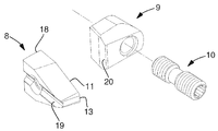
도 7 은 도 1 의 밀링 공구에서 사용된 밀링 인서트 및 체결 수단의 사시도를 도시한다.
도 8 은 본 발명의 실시형태에 따른 공구 보디의 단면도를 도시한다.
도 9 는 본 발명의 제 2 실시형태에 따른 밀링 공구의 사시도를 개략적으로 도시한다.Fig. 1 schematically shows a perspective view of a milling tool according to a first embodiment of the present invention together with a workpiece.
Fig. 2 shows a side view of the milling tool of Fig. 1 engaged with the workpiece.
Figure 3 shows a cross-sectional view of the milling tool of Figure 1 before engaging the workpiece.
Figure 4 shows a perspective view of the milling tool of Figure 1;
Figure 5 shows a side view of the milling tool of Figure 1;
Figure 6 shows a top view of the milling tool of Figure 1;
Figure 7 shows a perspective view of the milling insert and fastening means used in the milling tool of Figure 1;
8 shows a sectional view of a tool body according to an embodiment of the present invention.
9 schematically shows a perspective view of a milling tool according to a second embodiment of the present invention.
도 1 내지 도 6 은 본 발명의 제 1 실시형태에 따른 밀링 공구 (1) 를 개략적으로 도시하고, 상기 밀링 공구 (1) 는 이른바 호브 가공에 의하여 작업편 (30) 에서 외부 원통형 톱니들을 형성하기 위해 구성된다. 밀링 공구 (1) 는 밀링 머신 또는 멀티 작업 머신의 공구 스핀들 (2) 에 고정되고, 중앙 회전 축선 (C1) 을 중심으로 회전 방향 (R1) 으로 회전가능하다. 작업편 (30) 은 작업편 스핀들 (31) 에 고정되고, 중앙 회전 축선 (C2) 을 중심으로 회전 방향 (R2) 으로 회전가능하며, 이는 밀링 공구 (1) 및 작업편 (30) 이 웜 드라이브 (worm drive) 의 웜 및 웜 기어로서 각각 회전하게 한다. 밀링 공구 (1) 는 작업편 (30) 의 중앙 회전 축선 (C2) 과 평행한 이동 방향 (Z) 으로 작업편 (30) 에 대하여 이동가능하다. 명확성을 위해, 작업편 (30) 은 본 명세서에서 마감된 톱니들로, 즉 마감된 기계화 상태로 도시된다.1 to 6 schematically illustrate a
도 4 에 도시된 바와 같이, 밀링 공구는 두 개의 단부들, 이 실시형태에서는 공구 스핀들 (2) 에 고정되는 Coromant Capto® 부품의 형태로 고정 부재 (5) 를 구비하는 고정 단부 (4) 및 대향하는 외측 단부 (6) 를 갖는 공구 보디 (3) 를 포함한다. 주변 표면 (7) 은 외측 단부 (6) 와 고정 단부 (4) 사이의 중앙 회전 축선 (C1) 을 중심으로 연장한다. 다수의 이격된 절삭 치형부들은 공구 보디 (3) 에서 스크류들 (10) 로 체결된 클램프들 (9) 에 의해 공구 보디 (3) 의 인서트 시트들 (14) 에 단단하게 탑재된 동일한 절삭 인서트들 (8) 의 형태로 배치된다. 도 7 에서 훨씬 더 상세하게 도시된 각각의 절삭 인서트 (8) 는 절삭 날 (11) 및 칩 표면 (12) 을 포함하고, 상기 칩 표면 (12) 은 밀링 공구 (1) 의 회전 방향 (R1) 으로 보여지는 바와 같이 전방으로 향한다. 절삭 인서트들 (8) 은 리드 각 (β) 을 갖는 가상 나선의 두 개의 턴들을 따라서 탑재되고, 최전방 절삭 인서트 (8a) 로 시작하여 나선을 따라서 연속적으로 맞물리도록 배치된다. 본 명세서에서 리드 각 (β) 은 2.9°이지만, 밀링 공구의 직경에 따라 0.5°내지 10°사이에서, 더 구체적으로는 1°내지 5°사이에서 통상적으로 변할 수도 있고, 큰 직경들을 갖는 공구들은 비교적 작은 리드 각들로 통상적으로 구성된다. 나선을 따라서 두 개의 인접한 절삭 인서트들 (8) 사이의 거리는 인접한 절삭 인서트들 (8) 의 각각의 쌍에 대해 동등하고, 따라서 두 개의 인접한 절삭 인서트들 (8) 사이의 각 분리 (α) 에 대해 또한 동등하다. 각 분리 (α) 는 본 명세서에서 40°이지만, 18°내지 60°사이에서 변할 수도 있다. 도시된 실시형태에서, 밀링 공구 (1) 는 우선 리드으로 구성되고 스퍼 기어들 및 우선의 나선 기어들의 외부 호브 절삭에 적합하다.4, the milling tool has a fixed
절삭 인서트들 (8) 은 본 명세서에서 8 개의 절삭 인서트들 (8a ~ 8h) 을 포함하는 전방 단부 세트와 본 명세서에서 10 개의 절삭 인서트들 (8i) 을 포함하는 후방 단부 세트로서 배치된다. 전방 단부 세트의 절삭 인서트들 (8a ~ 8h) 은 중앙 회전 축선 (C1) 과 동심인 가상 나선의 전방 단부 부분을 따라서 배치된다. 전방 단부 부분은 본 명세서에서 절삭 인서트 (8a) 를 포함하는 나선의 일부로서 규정되고, 상기 절삭 인서트 (8a) 는 작업편 (30) 과 먼저 맞물린다. 밀링 공구 (1) 가 우선 리드으로 구성되는 도시된 실시형태에서, 나선의 전방 단부 부분은 공구 보디 (3) 의 외측 단부 (6) 에 가장 근접한 부분이다. 전방 단부 세트의 최전방 절삭 인서트 (8a) 로부터 전방 단부 세트의 마지막 절삭 인서트 (8h) 까지의 각 거리는 본 명세서에서 280°이다. 후방 단부 세트의 절삭 인서트들 (8i) 은 전방 단부 부분에 인접한 나선의 후방 단부 부분을 따라서 배치된다. 본 명세서에서, 절삭 인서트들 (8i) 의 후방 단부 세트는 전방 단부 세트의 최전방 절삭 인서트 (8a) 로부터 320°의 각 거리에서 개시한다. 후방 단부 세트의 절삭 인서트들 (8i) 은 중앙 회전 축선 (C1) 으로부터 제 1 방사상 거리 (r1) 에 모두 배치되고, 방사상 거리는 중앙 회전 축선 (C1) 으로부터 절삭 날 (11) 의 최외측 부분 (13) 까지의 거리로서 규정된다. 제 1 방사상 거리 (r1) 는 나선을 따라서 일정하여서, 절삭 인서트들 (8i) 모두는 중앙 회전 축선 (C1) 으로부터 동일한 거리에 각각의 절삭 날들 (11) 과 함께 배치된다.The cutting inserts 8 are arranged here as a set of front end sets comprising eight cutting
전방 단부 세트의 절삭 인서트들 (8a ~ 8h) 은 중앙 회전 축선 (C1) 으로부터 나선을 따라서 일정하지 않은 제 2 방사상 거리 (r2) 에서 배치된다. 도 6 에서 스파이럴 라인으로서 표시된 제 2 방사상 거리 (r2) 는 제 1 방사상 거리 (r1) 보다 더 작고, 최전방 절삭 인서트 (8a) 로부터 나선을 따라서 연속적으로 증가한다. 도시된 실시형태에서, 나선의 전방 단부 부분은 절단된 원추형 나선으로서, 더 구체적으로는 절단된 Archimedean 원추형 스파이럴으로서 형성되고, 나선은 밀링 공구 (1) 의 외측 단부 (6) 에서 절단된다. 밀링 공구 (1) 는 본 명세서에서 90㎜ 의 직경 (φ) 을 가지고 제 1 방사상 거리 (r1) 는 따라서 45㎜ 이다. 제 2 방사상 거리 (r2) 는 전방 단부 세트의 최전방 절삭 인서트 (8a) 에 대한 38.6㎜ 로부터 마지막 절삭 인서트 (8h) 에 대한 44.2㎜ 까지 각 절삭 인서트 (8a ~ 8h) 에 대해 일정한 거리 (Δd=0.8㎜) 로 서서히 증가한다. 도 5 에 도시된 바와 같이, 후방 단부 세트의 절삭 인서트들 (8i) 은, 절삭 치형부가 밀링 공구 (1) 의 주변 표면 (7) 으로부터 돌출하는, 공구의 방사상 방향으로 측정된 바와 같은 본 명세서에서 거리로서 규정되는 9.8㎜ 의 치형부 높이 (h) 를 가진다. 따라서, 이 실시형태에서 Δd=0.08h 이다.The front end sets of cutting
절삭 인서트들이 탑재되지 않은 공구 보디 (3) 가 도 8 에 도시된다. 공구 보디 (3) 는 중앙 회전 축선 (C1) 과 동심인 가상 나선을 따라서 주변 표면 (7) 에 배치되는 다수의 이격된 인서트 시트들 (14) 을 포함한다. 상기 인서트 시트들 (14) 의 전방 단부 세트는 본 명세서에서 나선의 전방 단부 부분을 따라서 배치된 8 개의 인서트 시트들 (14a ~ 14h) 을 포함하고, 상기 인서트 시트들 (14) 의 후방 단부 세트는 본 명세서에서 상기 나선의 인접한 후방 단부 부분을 따라서 배치된 인서트 시트들 (14i) 을 포함한다. 각각의 인서트 시트 (14) 는 절삭 인서트 (8) 를 수용하도록 배치되어서, 절삭 인서트들 (8) 은, 탑재 시에, 전방 단부 세트의 최전방 인서트 시트 (14a) 에 탑재된 절삭 인서트 (8a) 로 시작하는 나선을 따라서 작업편 (30) 과 연속적으로 맞물리도록 배치된다.The
각각의 인서트 시트 (14) 는 인서트 시트 (14) 에 탑재된 절삭 인서트 (8) 가 중앙 회전 축선 (C1) 을 향해 공구 보디 (3) 의 방사상 방향으로 이동하는 것을 방지하기 위해 스토핑 표면 (15) 의 형태로 스토핑 수단을 포함한다. 스토핑 표면 (15) 은 이러한 목적을 위해 공구 보디 (3) 의 방사상 방향에 대해 법선 (normal) 으로 배치되고 중앙 회전 축선 (C1) 과 평행하게 연장한다. 각각의 스토핑 표면 (15) 은 주변 표면 (7) 보다 중앙 회전 축선 (C1) 에 더 근접하게 배치되어서, 절삭 인서트 (8) 를 수용하기 위해 공구 보디 (3) 에 포켓이 형성된다. 후방 단부 세트의 인서트 시트들 (14i) 은 중앙 회전 축선 (C1) 으로부터 제 1 방사상 거리 (r3) 에 배치된 각각의 스토핑 표면들 (15i) 을 구비하고, 상기 제 1 방사상 거리 (r3) 는 나선을 따라서 일정하다. 따라서, 후방 단부 세트의 모든 스토핑 표면들 (15i) 은 중앙 회전 축선 (C1) 으로부터 동일한 거리에 배치된다.Each
전방 단부 세트의 인서트 시트들 (14a ~ 14h) 은 도 8 에서 스파이럴 라인으로 도시된, 중앙 회전 축선 (C1) 으로부터의 나선을 따라서 일정하지 않은 제 2 방사상 거리 (r4) 에 배치된 각각의 스토핑 표면들 (15a ~ 15h) 을 구비한다. 제 2 방사상 거리 (r4) 는 제 1 방사상 거리 (r3) 보다 더 작고, 최전방 인서트 시트 (14a) 로부터 나선을 따라서 연속적으로 증가한다. 도시된 실시형태에서, 나선의 전방 단부 부분은 절단된 원추형 나선으로서, 더 구체적으로는 절단된 Archimedean 원추형 스파이럴로서 형성된다. 도시된 실시형태에서, 각 인서트 시트 (14a ~ 14h) 에 대한 방사상 거리의 증가는 밀링 공구 (1) 에 대해 전술한 바와 같이 각 절삭 인서트 (8a ~ 8h) 에 대한 방사상 거리의 증가에 상응한다. 즉, 현재 실시형태에서 공구 보디 (3) 를 포함하는 밀링 공구 (1) 의 방사상 거리 (r2) 는 공구 보디 (3) 의 방사상 거리 (r4) 의 변함함에 의해 변하게 된다.The front end sets of
각각의 인서트 시트 (14) 는 공구 보디 (3) 의 주변 표면 (7) 으로부터 돌출하고 절삭 인서트 (8) 의 뒤에서 지지 구조체를 회전적으로 형성하는 돌기 (16) 를 추가로 포함한다. 돌기 (16) 에는, 잠금 리지 (17) 가 형성된다.Each
도 7 은 도시된 실시형태에 따라 밀링 공구 (1) 에서 사용된 절삭 인서트 (8), 클램프 (9) 및 스크류 (10) 를 도시한다. 절삭 인서트 (8) 는 이 실시형태에서 단면 절삭 인서트로서 형성된다. 절삭 인서트 (8) 는 공구 보디 (3) 의 방사상 스토핑 표면 (15) 에 기초하기 위한 지지 표면 (18) 을 포함한다. 그루브 (19) 는 잠금 리지 (17) 와의 맞물림을 위해 형성된다. 절삭 인서트 (8) 는 클램프 (9) 및 스크류 (10) 에 의해 인서트 시트 (14) 에 고정된다. 탑재 시에, 클램프 (9) 의 가압 표면 (20) 는 절삭 인서트 (8) 의 칩 표면 (12) 의 연장에 대항하여 가압하고, 이로 인해 인서트 시트 (14) 에 고정된다. 절삭 인서트는, 탑재 시에, 작업편 (30) 과의 맞물림을 절단하기 위해 공구 보디 (3) 로부터 돌기 (16) 를 지나서 방사상으로 돌출한다.Figure 7 shows the cutting
도 1 내지 도 3 에 도시된 바와 같이, 기계 가공 프로세스에서, 밀링 공구 (1) 는 회전 방향 (R1) 으로 고속으로 회전하도록 설정된다. 작업편 (30) 은 회전 방향 (R2) 으로 상당하게 더 낮은 속도로 회전하도록 설정되고, 이는 밀링 공구 (1) 가 잡업편 (30) 을 최전방 절삭 인서트 (8a) 와 먼저 맞물리게 한 후, 절삭 인서트 (8b) 등과 맞물리게 선택되었다. 이로 인해, 각각의 절삭 인서트 (8) 는 작업편 (30) 으로부터 재료를 제거한다. 스퍼 기어의 밀링을 위하여, 밀링 공구 (1) 의 중앙 회전 축선 (C1) 이 나선의 리드 각 (β) 에 상응하는 각도로 작업편 (30) 의 회전 방향 (R2) 에 대해 틸팅된다. 밀링 공구 (30) 는 작업편 (30) 에 대해 방향 (Z) 으로 이송되고, 톱니들은 이로 인해 작업편에 형성된다. 절삭 인서트들 (8i) 의 후방 단부 세트들 보다 이전에 작업편 (30) 과 맞물리는 절삭 인서트들 (8a ~ 8h) 의 전방 단부 세트는 톱니들의 황삭 및 예비 성형 (preforming) 을 실시한다. 후방 단부 세트의 절삭 인서트들 (8i) 은 톱니들이 최종 인벌류트 형상을 갖게 한다.As shown in Figs. 1 to 3, in the machining process, the
도 9 는 본 발명의 제 2 실시형태에 따른 밀링 공구 (1) 를 개략적으로 도시한다. 밀링 공구 (1) 는 이 실시형태에서 단지 밀링 공구가 좌선 리드으로 구성된다는 점에서 제 1 실시형태의 밀링 공구 (1) 와 상이하다. 이로 인해, 중앙 회전 축선 (C1) 으로부터 최소 방사상 거리에 위치된 최전방 절삭 인서트 (8a) 는 밀링 공구 (1) 의 고정 단부 (4) 에 가장 근접하게 위치된다. 후방 단부 세트의 절삭 인서트들 (8i) 은 밀링 공구 (1) 의 외측 단부 (6) 에 근접하게 위치된다. 사용 시에, 밀링 공구 (1) 가 맞물리기 위한 작업편의 회전 방향은, 최전방 절삭 인서트 (8a) 가 작업편과 먼저 맞물리게 되어야 한다. 제 1 실시형태와 비교해 볼 때, 작업편의 회전은 역전되어야 한다. 밀링 공구 (1) 는 이 실시형태에서 스퍼 기어들의 호브 절삭에 적합하고, 이 경우 밀링 공구는 좌선의 나선 기어들 및 작업편의 회전 방향에 대해 틸팅되어야 한다.Fig. 9 schematically shows a
본 발명은 개시된 실시형태들에 제한되지 않고, 이하의 청구항들의 범위 내에서 변하게 되고 수정될 수도 있다. 예를 들어, EP2487000 에 개시된 종류의 색인가능한 절삭 인서트들과 같은 다른 종류의 절삭 인서트들이 사용될 수도 있다. 또한, 스크류들과 같은 절삭 인서트들을 체결하는 다른 수단들이 사용될 수도 있다. 또한, 절삭 인서트들의 디자인에 의해 적어도 부분적으로 제 2 방사상 거리 (r2) 를 변하게 하는 것이 가능하다. 예를 들어, 절삭 인서트들의 전방 단부 세트의 적어도 일부는 절삭 인서트들의 나머지보다 더 작아질 수도 있고, 그리고/또는 더 큰 곡률 반경을 갖는 절삭 날을 구비할 수도 있다.The invention is not limited to the disclosed embodiments, but may be varied and modified within the scope of the following claims. Other types of cutting inserts, for example indexable cutting inserts of the kind disclosed in EP 2487000, may be used. Other means of fastening the cutting inserts, such as screws, may also be used. It is also possible, at least in part, to change the second radial distance r2 by design of the cutting inserts. For example, at least a portion of the front end set of cutting inserts may be smaller than the remainder of the cutting inserts, and / or may have a cutting edge with a larger radius of curvature.
또한, 전방 단부 세트에서뿐만 아니라 후방 단부 세트에서 절삭 치형부들의 수, 공구의 직경, 및 나선의 각 턴에 대한 절삭 치형부들의 수를 변하게 하는 것이 가능하다. 나선을 따라서 인접한 절삭 치형부들 사이의, 또는 공구 보디의 경우에 나선을 따라서 인접한 인서트 시트들 사이의 전방 단부 세트 내에서 제 2 방사상 거리의 증가는 나선을 따라서 동등해질 필요가 없으며, 나선을 따라서 변할 수도 있다.It is also possible to vary not only the front end set but also the number of cut teeth portions, the diameter of the tool, and the number of cut teeth portions for each turn of the spiral in the rear end set. The increase of the second radial distance in the set of front ends between adjacent insert teeth along the helix, or between adjacent insert sheets along the helix in the case of the tool body, does not need to be equal along the helix, It is possible.
물론, 밀링 공구는 솔레노이드 고속 스틸 공구와 같은 공구 보디와 통합된 교체불가능한 절삭 치형부들을 구비하는 밀링 공구의 형태로 또한 있을 수도 있다. 그러한 경우에, 절삭 치형부들의 전방 단부 세트 내에서 일정하지 않은 제 2 방사상 거리는 공구의 주변 표면에 대해 절삭 치형부들의 설치에 의해 또는 절삭 치형부들의 디자인에 의해 변할 수도 있다.Of course, the milling tool may also be in the form of a milling tool with non-replaceable cutter teeth integrated with a tool body such as a solenoid high-speed steel tool. In such a case, the second radial distance which is not constant in the set of front ends of the toothed portions may be changed by the installation of the toothed portions with respect to the peripheral surface of the tool or by the design of the toothed portions.
전술한 밀링 공구는 단일 나사 구비 밀링 공구, 즉 단일 나선 라인을 따라서 배치된 절삭 치형부들을 구비하는 밀링 공구의 형태로 있다. 하지만, 이중 나사 구비 또는 심지어 삼중 나사 구비 밀링 공구로서 본 발명에 따른 밀링 공구를 구성하는 것이 또한 가능하고, 상기 경우 밀링 공구의 리드 각은 상응하는 단일 나사 구비 밀링 공구와 비교하여 증가된다.The milling tool described above is in the form of a milling tool with a single screw, i.e. a milling tool with cutting teeth arranged along a single line of spirals. However, it is also possible to construct a milling tool according to the invention as a milling tool with a double screw or even a triple screw, in which case the lead angle of the milling tool is increased compared to the corresponding single screw milling tool.
또한, 밀링 공구는, EP2662173 및 EP2537617 에서 개시된 것과 같은 밀링 공구의 양 단부들에서 지지체를 제공하기 위하여 밀링 공구의 외측 단부에서 밀링 공구를 예컨대 베어링 브래킷 (bearing bracket) 에 연결하기 위한 수단을 포함한다.The milling tool also includes means for connecting the milling tool to the bearing bracket at the outer end of the milling tool, for example, to provide a support at both ends of the milling tool, such as those disclosed in EP2662173 and EP2537617.
1
밀링 공구
2
공구 스핀들
3
공구 보디
4
고정 단부
5
고정 부재
6
외측 단부
7
주변 표면
8
절삭 인서트
9
클램프
10
스크류
11
절삭 날
12
칩 표면
13
절삭 날의 최외측 부분
14
인서트 시트
15
스토핑 표면
16
돌기
17
잠금 리지
18
지지 표면
19
그루브
20
가압 표면
30
작업편
31
작업편 스핀들
C1
공구의 중앙 회전 축선
C2
작업편의 중앙 회전 축선
R1
공구의 회전 방향
R2
작업편의 회전 방향
Z
이동 방향
α
각 분리
β
리드 각
φ
공구 직경
r1
공구의 제 1 방사상 거리
r2
공구의 제 2 방사상 거리
r3
공구 보디의 제 1 방사상 거리
r4
공구 보디의 제 2 방사상 거리
h
치형부 높이1
3
5 Fixing
7 Surrounding
9
11
13 Outermost portion of cutting
15 stopping
17
19
30
C1 Centering axis of the tool C2 Centering axis of the workpiece
R1 Direction of rotation of the tool R2 Direction of rotation of the workpiece
Z direction of movement α separation
β lead angle φ tool diameter
r1 the first radial distance of the tool r2 the second radial distance of the tool
r3 the first radial distance of the tool body r4 the second radial distance of the tool body
the tooth height h
Claims (17)
상기 밀링 공구 (1) 는:
- 주변 표면 (7) 및 두 개의 대향 단부들 (4, 6) 을 구비하는 공구 보디 (3) 로서, 상기 두 개의 대향 단부들 (4, 6) 사이에서 중앙 회전 축선 (C1) 이 연장하고, 상기 공구 보디 (3) 는 상기 중앙 회전 축선 (C1) 을 중심으로 미리 정해진 회전 방향 (R1) 으로 회전가능한, 상기 공구 보디 (3),
- 상기 주변 표면으로부터 돌출하는 다수의 이격된 절삭 치형부들 (8) 로서, 각각의 절삭 치형부 (8) 는 절삭 날 (11) 과 칩 표면 (12) 을 포함하는, 상기 다수의 이격된 절삭 치형부들 (8)
을 포함하고,
상기 절삭 치형부들 (8a ~ 8h) 의 전방 단부 세트는 상기 중앙 회전 축선 (C1) 과 동심인 가상 나선의 전방 단부 부분을 따라서 배치되고, 상기 절삭 치형부들 (8i) 의 후방 단부 세트는 상기 나선의 인접한 후방 단부 부분을 따라서 배치되고, 상기 절삭 치형부들 (8) 은 상기 전방 단부 세트의 최전방 절삭 치형부 (8a) 로 시작하여 상기 나선을 따라서 작업편과 연속적으로 맞물리도록 배치되고,
상기 절삭 치형부들 (8i) 의 후방 단부 세트는 상기 중앙 회전 축선 (C1) 으로부터 상기 나선을 따라서 일정한 제 1 방사상 거리 (an along the helix constant first radial distance; r1) 에 배치된 적어도 세 개의 나선을 따라서 인접한 절삭 치형부들 (8i) 을 포함하고,
상기 절삭 치형부들 (8a ~ 8h) 의 전방 단부 세트는 상기 중앙 회전 축선 (C1) 으로부터 상기 나선을 따라서 일정하지 않은 제 2 방사상 거리 (an along the helix non-constant second radial distance; r2) 에 배치된 적어도 두 개의 상기 나선을 따라서 인접한 절삭 치형부들 (8a ~ 8h) 을 포함하고,
상기 제 2 방사상 거리 (r2) 는 상기 제 1 방사상 거리 (r1) 보다 더 작고 최전방 절삭 치형부 (8a) 로부터 상기 나선을 따라서 연속적으로 증가하는 것을 특징으로 하는, 밀링 공구.1. A milling tool (1) for hobbing a workpiece (30) having cylindrical teeth (cogs) such as gear wheels or having racks,
The milling tool (1) comprises:
A tool body (3) having a peripheral surface (7) and two opposite ends (4, 6), the central axis of rotation (C1) extending between the two opposite ends (4, 6) The tool body 3 is rotatable in a predetermined rotational direction R1 about the central rotation axis C1. The tool body 3,
- a plurality of spaced apart tooth teeth (8) projecting from said peripheral surface, each cutting tooth (8) comprising a cutting edge (11) and a chip surface (12) (8)
/ RTI >
Wherein a set of front ends of the cut teeth 8a-8h are arranged along a front end portion of a virtual helix concentric with the central axis of rotation C1, Wherein the cutting teeth (8) are arranged to engage successively with the workpiece along the spiral starting with the forefront cutting tooth (8a) of the front end set,
The set of rear ends of the toothed teeth 8i are arranged along at least three spirals arranged at a constant first radial distance r1 from the central axis of rotation C1 along the helix Includes adjacent tooth portions 8i,
The set of front ends of the toothed portions 8a-8h are arranged in a second non-constant second radial distance r2 along the helix from the central axis of rotation C1. (8a-8h) adjacent to each other along at least two of said helixes,
Characterized in that the second radial distance r2 is smaller than the first radial distance r1 and continuously increases along the helix from the forefront cutting tooth 8a.
상기 제 2 방사상 거리 (r2) 는 상기 나선을 따라서 각 절삭 치형부 (8a ~ 8h) 에 대해 거리 Δd 로 증가하고, 여기서 Δd 는 상기 최전방 절삭 치형부 (8a) 로부터의 각 (angular) 거리의 함수인 것을 특징으로 하는, 밀링 공구.The method according to claim 1,
The second radial distance r2 increases along the spiral to a distance? D with respect to each cutting tooth 8a-8h, where? D is the angular distance from the forefront cutting tooth 8a Of the milling tool.
상기 거리 Δd 는 상기 나선을 따라서 인접한 절삭 치형부들 (8a ~ 8h) 의 각각의 쌍에 대해 일정하거나 실질적으로 일정한 것을 특징으로 하는, 밀링 공구.3. The method of claim 2,
Characterized in that said distance DELTA d is constant or substantially constant for each pair of adjacent toothed portions (8a-8h) along said helix.
상기 거리 Δd 는 상기 나선을 따라서 일정하지 않은 것을 특징으로 하는, 밀링 공구.3. The method of claim 2,
Characterized in that said distance DELTA d is not constant along said helix.
상기 제 2 방사상 거리 (r2) 는 상기 나선을 따라서 각 절삭 치형부에 대해
0.02h ≤ Δd ≤ 0.1h ㎜
의 거리 Δd 로 증가하고, 여기서 h 는 상기 후방 단부 세트의 절삭 치형부 (8i) 의 치형부 높이인 것을 특징으로 하는, 밀링 공구.5. The method according to any one of claims 1 to 4,
The second radial distance (r2) is defined for each tooth tooth along the spiral
0.02 h ?? D ? 0.1h mm
Increase in the distance Δ d, where h is, the milling tool, characterized in that the tooth height of the cutting teeth (8i) of the rear end sets.
상기 전방 단부 부분은 상기 나선의 적어도 하나의 완전한 턴 (turn) 을 따라서 연장하는 것을 특징으로 하는, 밀링 공구.6. The method according to any one of claims 1 to 5,
Said front end portion extending along at least one complete turn of said spiral.
상기 나선은 일정한 또는 실질적으로 일정한 축방향 피치를 갖는 것을 특징으로 하는, 밀링 공구.7. The method according to any one of claims 1 to 6,
Characterized in that said spiral has a constant or substantially constant axial pitch.
상기 나선을 따라서 인접한 절삭 치형부들 (8) 의 각각의 쌍 사이에서의 각 (angular) 분리는 일정하거나 실질적으로 일정한 것을 특징으로 하는, 밀링 공구.8. The method according to any one of claims 1 to 7,
Characterized in that the angular separation between each pair of adjacent cutting teeth (8) along the spiral is constant or substantially constant.
상기 후방 단부 세트의 모든 절삭 치형부들 (8i) 은 상기 중앙 회전 축선 (C1) 으로부터 상기 일정한 제 1 방사상 거리 (r1) 에 배치되는 것을 특징으로 하는, 밀링 공구.9. The method according to any one of claims 1 to 8,
Characterized in that all the toothed portions (8i) of the rear end set are arranged at the constant first radial distance (r1) from the central rotation axis (C1).
상기 절삭 치형부들 (8) 은 상기 나선의 적어도 두 개의 완전한 턴들을 따라서 배치되는 것을 특징으로 하는, 밀링 공구.10. The method according to any one of claims 1 to 9,
Characterized in that said cutting teeth (8) are arranged along at least two complete turns of said helix.
상기 절삭 치형부들 (8) 은 교체가능한 절삭 인서트들 (8) 로서 구성되는 것을 특징으로 하는, 밀링 공구.11. The method according to any one of claims 1 to 10,
Characterized in that the cutting teeth (8) are configured as interchangeable cutting inserts (8).
상기 절삭 인서트들 (8) 모두는 동일한 것을 특징으로 하는, 밀링 공구.12. The method of claim 11,
Characterized in that all of the cutting inserts (8) are identical.
상기 공구 보디 (3) 는:
- 주변 표면 (7) 및 두 개의 대향 단부들 (4, 6) 로서, 상기 두 개의 대향 단부들 (4, 6) 사이에서 중앙 회전 축선 (C1) 이 연장하고, 상기 공구 보디 (3) 는 상기 중앙 회전 축선 (C1) 을 중심으로 미리 정해진 회전 방향 (R1) 으로 회전가능한, 상기 주변 표면 (7) 및 두 개의 대향 단부들 (4, 6),
- 상기 주변 표면 (7) 내에 배치된 다수의 이격된 인서트 시트들 (14)
을 포함하고,
상기 인서트 시트들 (14a ~ 14h) 의 전방 단부 세트는 상기 중앙 회전 축선 (C1) 과 동심인 가상 나선의 전방 단부 부분을 따라서 배치되고, 상기 인서트 시트들 (14i) 의 후방 단부 세트는 상기 나선의 인접한 후방 단부 부분을 따라서 배치되고, 각각의 인서트 시트 (14) 는 상기 절삭 인서트 (8) 를 수용하도록 배치되어서, 절삭 인서트들 (8) 이, 탑재 시에, 상기 전방 단부 세트의 최전방 인서트 시트 (14a) 내에 탑재된 상기 절삭 인서트 시트 (8a) 로 시작하여 상기 나선을 따라서 상기 작업편 (30) 에 연속적으로 맞물리도록 배치되고,
각각의 인서트 시트 (14) 는 방사상 방향으로 각각의 상기 절삭 인서트 (8) 를 고정하기 위한 스토핑 수단 (15; stopping means) 을 포함하고,
상기 인서트 시트들 (14i) 의 후방 단부 세트는 상기 중앙 회전 축선 (C1) 으로부터 상기 나선을 따라서 일정한 제 1 방사상 거리 (r3) 에 배치된 각각의 스토핑 수단 (15i) 을 구비하는 적어도 세 개의 나선을 따라서 인접한 인서트 시트들 (14i) 을 포함하고,
상기 인서트 시트들 (14a ~ 14b) 의 전방 단부 세트는 상기 중앙 회전 축선 (C1) 으로부터 상기 나선을 따라서 일정하지 않은 제 2 방사상 거리 (r4) 에 배치된 각각의 스토핑 수단 (15a ~ 15h) 을 구비하는 적어도 두 개의 나선을 따라서 인접한 인서트 시트들 (14a ~ 14b) 을 포함하고,
상기 제 2 방사상 거리 (r4) 는 상기 제 1 방사상 거리 (r3) 보다 더 작고 상기 최전방 인서트 시트 (14a) 로부터 나선을 따라서 연속적으로 증가하는 것을 특징으로 하는, 밀링 공구 (10) 용 공구 보디 (3).A tool body (3) for a milling tool (10) formed for hob cutting of a workpiece (30) with or without cylindrical teeth such as gear wheels,
The tool body (3) comprises:
A central rotation axis C1 extends between the two opposing ends 4 and 6 as a peripheral surface 7 and two opposite ends 4 and 6, The peripheral surface 7 and the two opposing ends 4, 6, which are rotatable in a predetermined rotational direction R1 about the central rotation axis C1,
A plurality of spaced apart insert sheets (14) arranged in said peripheral surface (7)
/ RTI >
Wherein a set of front ends of the insert sheets 14a to 14h are disposed along a front end portion of a virtual helix concentric with the central rotational axis C1 and a set of rear ends of the insert sheets 14i- And each insert seat 14 is arranged to receive the cutting insert 8 such that the cutting inserts 8 are mounted on the foremost insert seat of the front end set 14a) and continuously engaged with the workpiece (30) along the spiral,
Each insert sheet 14 comprises stopping means 15 for fixing each of said cutting inserts 8 in a radial direction,
The set of rear ends of the insert sheets 14i comprises at least three spirals 15i each with respective stopping means 15i arranged at a first predetermined radial distance r3 along the spiral from the central rotation axis C1, , Adjacent insert sheets (14i)
The set of front ends of the insert sheets 14a-14b includes respective stopping means 15a-15h disposed at a second radial distance r4 not constant along the spiral from the central rotation axis C1 And adjacent insert sheets (14a-14b) along at least two spirals,
Characterized in that the second radial distance r4 is smaller than the first radial distance r3 and increases continuously along the spiral from the forefront insert seat 14a, ).
상기 나선의 상기 전방 단부 부분은 절단된 원추형 나선의 일부로서 형성되는 것을 특징으로 하는, 밀링 공구 (10) 용 공구 보디 (3).14. The method of claim 13,
Characterized in that said front end portion of said helix is formed as part of a truncated conical helix.
상기 나선의 상기 전방 단부 부분은 상기 나선의 적어도 하나의 완전한 턴을 따라서 연장하는 것을 특징으로 하는, 밀링 공구 (10) 용 공구 보디 (3).The method according to claim 13 or 14,
Characterized in that said front end portion of said helix extends along at least one complete turn of said helix.
상기 공구 보디 (3) 는 적어도 두 개의 분리가능하게 상호 연결된 디스크 형상의 세그먼트들을 포함하고, 각각의 세그먼트는 상기 중앙 회전 축선에 수직으로 연장하는 두 개의 대향 평면-평행 단부 표면들을 갖는 허브 부재, 적어도 두 개의 이격된 절삭 인서트들을 수용하기 위해 구성된 주변 캠, 및 세그먼트를 이웃하는 세그먼트와 상호 연결하기 위한 상호 연결 수단을 포함하는 것을 특징으로 하는, 밀링 공구 (10) 용 공구 보디 (3).16. The method according to any one of claims 13 to 15,
The tool body (3) comprises at least two removably interconnected disk-shaped segments, each segment having a hub member having two opposing planar-parallel end surfaces extending perpendicularly to the central axis of rotation A peripheral cam configured to receive two spaced apart cutting inserts, and interconnecting means for interconnecting the segments with neighboring segments.
상기 세그먼트는 상기 인서트 시트들의 전방 단부 세트의 적어도 일부를 포함하는, 공구 보디용 세그먼트.A segment for a tool body according to claim 16,
Wherein the segment comprises at least a portion of a set of front ends of the insert sheets.
Applications Claiming Priority (2)
| Application Number | Priority Date | Filing Date | Title |
|---|---|---|---|
| EP14167187.5A EP2942140A1 (en) | 2014-05-06 | 2014-05-06 | A milling tool and a tool body |
| EP14167187.5 | 2014-05-06 |
Publications (1)
| Publication Number | Publication Date |
|---|---|
| KR20150126996A true KR20150126996A (en) | 2015-11-16 |
Family
ID=50630698
Family Applications (1)
| Application Number | Title | Priority Date | Filing Date |
|---|---|---|---|
| KR1020150062237A Withdrawn KR20150126996A (en) | 2014-05-06 | 2015-05-01 | A milling tool and a tool body |
Country Status (7)
| Country | Link |
|---|---|
| US (1) | US10099304B2 (en) |
| EP (1) | EP2942140A1 (en) |
| JP (1) | JP2015212006A (en) |
| KR (1) | KR20150126996A (en) |
| CN (1) | CN105081429A (en) |
| BR (1) | BR102015010149A2 (en) |
| RU (1) | RU2015116857A (en) |
Families Citing this family (7)
| Publication number | Priority date | Publication date | Assignee | Title |
|---|---|---|---|---|
| EP2965847B1 (en) * | 2014-07-09 | 2019-09-11 | Sandvik Intellectual Property AB | Cutting insert and power skiving tool |
| US20170014923A1 (en) * | 2015-07-14 | 2017-01-19 | Caterpillar Inc. | Dual Ended, Full Form Tooth Generating Gear Cutter and Associated Cutting Insert |
| MX392437B (en) * | 2015-08-10 | 2025-03-24 | Illinois Tool Works | CUTTING TOOL FOR A TRAVELING LARGE DIAMETER PIPE CUTTER. |
| EP3834975B1 (en) | 2015-08-10 | 2025-10-01 | Illinois Tool Works INC. | Large diameter travelling pipe cutter |
| US10654117B2 (en) * | 2016-03-03 | 2020-05-19 | Kennametal Inc. | Cutting tool assembly for milling a rail top |
| JP6367889B2 (en) * | 2016-10-25 | 2018-08-01 | 三菱重工工作機械株式会社 | Skiving cutter |
| CN107008957B (en) * | 2017-06-14 | 2019-05-21 | 河南科技大学 | Facing cutter is used in a kind of processing of equal-depth teeth |
Family Cites Families (15)
| Publication number | Priority date | Publication date | Assignee | Title |
|---|---|---|---|---|
| US688098A (en) * | 1901-07-31 | 1901-12-03 | Firm Of Friedrich Stolzenberg & Co | Worm-wheel-cutting tool. |
| US1430485A (en) * | 1921-01-28 | 1922-09-26 | Gould & Eberhardt | Hob and method of making it |
| US1648470A (en) * | 1922-11-20 | 1927-11-08 | Cleveland Worm And Gear Compan | Hob for worm gears |
| US1728198A (en) * | 1927-06-30 | 1929-09-17 | Timken Axle Co Detroit | Hob |
| US1765853A (en) * | 1927-08-27 | 1930-06-24 | Nat Tool Company | Worm generating hob |
| GB794912A (en) * | 1954-03-12 | 1958-05-14 | Wolfram Lindner | Improvements in or relating to single-start or multiple-start hobs |
| DE965775C (en) * | 1955-05-11 | 1957-06-19 | Klingelnberg Soehne Ferd | Assembled screw hobbing cutter |
| DE1049195B (en) * | 1955-06-04 | 1959-01-22 | Klingelnberg Soehne Ferd | Profile milling cutter with multiple cutting edges |
| DE1083621B (en) * | 1956-02-14 | 1960-06-15 | Fritz Werner Ag | Weakly conical worm mill or taps |
| US3371396A (en) * | 1966-04-07 | 1968-03-05 | Barber Colman Co | Cutter for milling gears and the like |
| JPS52159493U (en) * | 1976-05-28 | 1977-12-03 | ||
| SE535540C2 (en) | 2011-02-11 | 2012-09-18 | Sandvik Intellectual Property | Milling tools for tooth milling |
| SE536294C2 (en) * | 2011-04-08 | 2013-08-06 | Sandvik Intellectual Property | Milling tools designed for hobbing a workpiece |
| SE535941C2 (en) | 2011-06-20 | 2013-02-26 | Sandvik Intellectual Property | Milling tools for hobbing and segments for this |
| SE536487C2 (en) * | 2012-05-09 | 2013-12-17 | Sandvik Intellectual Property | Milling tools for hobbing |
-
2014
- 2014-05-06 EP EP14167187.5A patent/EP2942140A1/en not_active Withdrawn
-
2015
- 2015-04-09 JP JP2015079780A patent/JP2015212006A/en not_active Withdrawn
- 2015-04-30 RU RU2015116857A patent/RU2015116857A/en not_active Application Discontinuation
- 2015-05-01 KR KR1020150062237A patent/KR20150126996A/en not_active Withdrawn
- 2015-05-04 CN CN201510220837.1A patent/CN105081429A/en active Pending
- 2015-05-05 BR BR102015010149-0A patent/BR102015010149A2/en not_active IP Right Cessation
- 2015-05-05 US US14/703,947 patent/US10099304B2/en not_active Expired - Fee Related
Also Published As
| Publication number | Publication date |
|---|---|
| CN105081429A (en) | 2015-11-25 |
| RU2015116857A3 (en) | 2018-11-06 |
| BR102015010149A2 (en) | 2018-05-02 |
| US20150321276A1 (en) | 2015-11-12 |
| US10099304B2 (en) | 2018-10-16 |
| RU2015116857A (en) | 2016-11-20 |
| EP2942140A1 (en) | 2015-11-11 |
| JP2015212006A (en) | 2015-11-26 |
Similar Documents
| Publication | Publication Date | Title |
|---|---|---|
| KR20150126996A (en) | A milling tool and a tool body | |
| KR101746078B1 (en) | Machine tool and method for producing gearing | |
| JP6128997B2 (en) | Milling insert | |
| US20250058389A1 (en) | Chamfering tool, chamfering system, gear-cutting machine and method for chamfering toothings | |
| JP5902564B2 (en) | Milling tools and segments | |
| EP2659999B1 (en) | A milling tool | |
| US8678714B2 (en) | Milling tool, and milling insert kit | |
| RU2593882C2 (en) | Gear-milling cutter, end milling cutter and routing method | |
| EP2433735B1 (en) | A gear milling cutter as well as a set of gear milling cutter inserts therefor | |
| US20140206269A1 (en) | Tool for Grinding Toothed Workpieces Having Collision Contours | |
| CA2714509C (en) | Form tap having a plurality of lobes | |
| KR20120139595A (en) | Method for gear pre-cutting of a plurality of different bevel gears and use of an according milling tool | |
| JP2021514862A5 (en) | ||
| KR20170015925A (en) | Thread milling cutter | |
| US20170087647A1 (en) | Rotary cutting tool | |
| JP5162920B2 (en) | Gear processing method and gear processing apparatus | |
| JP2024516564A (en) | High Feed Circle Segment Cutter | |
| CN115319205A (en) | Turning machine tool and method for straight-profile enveloping worm | |
| RU2298461C1 (en) | Screw grinder | |
| EP3187293A1 (en) | Modular screw cutter | |
| UA60011A (en) | hobbing cutter |
Legal Events
| Date | Code | Title | Description |
|---|---|---|---|
| PA0109 | Patent application |
Patent event code: PA01091R01D Comment text: Patent Application Patent event date: 20150501 |
|
| PG1501 | Laying open of application | ||
| PC1203 | Withdrawal of no request for examination |