KR20150023853A - Variable angle bone fixation device - Google Patents
Variable angle bone fixation device Download PDFInfo
- Publication number
- KR20150023853A KR20150023853A KR20157001705A KR20157001705A KR20150023853A KR 20150023853 A KR20150023853 A KR 20150023853A KR 20157001705 A KR20157001705 A KR 20157001705A KR 20157001705 A KR20157001705 A KR 20157001705A KR 20150023853 A KR20150023853 A KR 20150023853A
- Authority
- KR
- South Korea
- Prior art keywords
- bone
- bone fixation
- head
- plate
- screw
- Prior art date
- Legal status (The legal status is an assumption and is not a legal conclusion. Google has not performed a legal analysis and makes no representation as to the accuracy of the status listed.)
- Granted
Links
Images


Classifications
-
- A—HUMAN NECESSITIES
- A61—MEDICAL OR VETERINARY SCIENCE; HYGIENE
- A61B—DIAGNOSIS; SURGERY; IDENTIFICATION
- A61B17/00—Surgical instruments, devices or methods
- A61B17/56—Surgical instruments or methods for treatment of bones or joints; Devices specially adapted therefor
- A61B17/58—Surgical instruments or methods for treatment of bones or joints; Devices specially adapted therefor for osteosynthesis, e.g. bone plates, screws or setting implements
- A61B17/68—Internal fixation devices, including fasteners and spinal fixators, even if a part thereof projects from the skin
- A61B17/80—Cortical plates, i.e. bone plates; Instruments for holding or positioning cortical plates, or for compressing bones attached to cortical plates
- A61B17/8052—Cortical plates, i.e. bone plates; Instruments for holding or positioning cortical plates, or for compressing bones attached to cortical plates immobilised relative to screws by interlocking form of the heads and plate holes, e.g. conical or threaded
- A61B17/8057—Cortical plates, i.e. bone plates; Instruments for holding or positioning cortical plates, or for compressing bones attached to cortical plates immobilised relative to screws by interlocking form of the heads and plate holes, e.g. conical or threaded the interlocking form comprising a thread
-
- A—HUMAN NECESSITIES
- A61—MEDICAL OR VETERINARY SCIENCE; HYGIENE
- A61B—DIAGNOSIS; SURGERY; IDENTIFICATION
- A61B17/00—Surgical instruments, devices or methods
- A61B17/56—Surgical instruments or methods for treatment of bones or joints; Devices specially adapted therefor
- A61B17/58—Surgical instruments or methods for treatment of bones or joints; Devices specially adapted therefor for osteosynthesis, e.g. bone plates, screws or setting implements
- A61B17/68—Internal fixation devices, including fasteners and spinal fixators, even if a part thereof projects from the skin
- A61B17/80—Cortical plates, i.e. bone plates; Instruments for holding or positioning cortical plates, or for compressing bones attached to cortical plates
- A61B17/8052—Cortical plates, i.e. bone plates; Instruments for holding or positioning cortical plates, or for compressing bones attached to cortical plates immobilised relative to screws by interlocking form of the heads and plate holes, e.g. conical or threaded
-
- A—HUMAN NECESSITIES
- A61—MEDICAL OR VETERINARY SCIENCE; HYGIENE
- A61B—DIAGNOSIS; SURGERY; IDENTIFICATION
- A61B17/00—Surgical instruments, devices or methods
- A61B17/56—Surgical instruments or methods for treatment of bones or joints; Devices specially adapted therefor
- A61B17/58—Surgical instruments or methods for treatment of bones or joints; Devices specially adapted therefor for osteosynthesis, e.g. bone plates, screws or setting implements
- A61B17/68—Internal fixation devices, including fasteners and spinal fixators, even if a part thereof projects from the skin
- A61B17/84—Fasteners therefor or fasteners being internal fixation devices
- A61B17/86—Pins or screws or threaded wires; nuts therefor
- A61B17/8605—Heads, i.e. proximal ends projecting from bone
- A61B17/861—Heads, i.e. proximal ends projecting from bone specially shaped for gripping driver
- A61B17/8615—Heads, i.e. proximal ends projecting from bone specially shaped for gripping driver at the central region of the screw head
-
- A—HUMAN NECESSITIES
- A61—MEDICAL OR VETERINARY SCIENCE; HYGIENE
- A61B—DIAGNOSIS; SURGERY; IDENTIFICATION
- A61B17/00—Surgical instruments, devices or methods
- A61B17/56—Surgical instruments or methods for treatment of bones or joints; Devices specially adapted therefor
- A61B17/58—Surgical instruments or methods for treatment of bones or joints; Devices specially adapted therefor for osteosynthesis, e.g. bone plates, screws or setting implements
- A61B17/68—Internal fixation devices, including fasteners and spinal fixators, even if a part thereof projects from the skin
- A61B17/84—Fasteners therefor or fasteners being internal fixation devices
- A61B17/86—Pins or screws or threaded wires; nuts therefor
- A61B17/8625—Shanks, i.e. parts contacting bone tissue
- A61B17/863—Shanks, i.e. parts contacting bone tissue with thread interrupted or changing its form along shank, other than constant taper
-
- A—HUMAN NECESSITIES
- A61—MEDICAL OR VETERINARY SCIENCE; HYGIENE
- A61B—DIAGNOSIS; SURGERY; IDENTIFICATION
- A61B17/00—Surgical instruments, devices or methods
- A61B17/56—Surgical instruments or methods for treatment of bones or joints; Devices specially adapted therefor
- A61B17/58—Surgical instruments or methods for treatment of bones or joints; Devices specially adapted therefor for osteosynthesis, e.g. bone plates, screws or setting implements
- A61B17/68—Internal fixation devices, including fasteners and spinal fixators, even if a part thereof projects from the skin
- A61B17/84—Fasteners therefor or fasteners being internal fixation devices
- A61B17/86—Pins or screws or threaded wires; nuts therefor
- A61B17/8625—Shanks, i.e. parts contacting bone tissue
- A61B17/8635—Tips of screws
-
- A—HUMAN NECESSITIES
- A61—MEDICAL OR VETERINARY SCIENCE; HYGIENE
- A61B—DIAGNOSIS; SURGERY; IDENTIFICATION
- A61B17/00—Surgical instruments, devices or methods
- A61B17/56—Surgical instruments or methods for treatment of bones or joints; Devices specially adapted therefor
- A61B17/58—Surgical instruments or methods for treatment of bones or joints; Devices specially adapted therefor for osteosynthesis, e.g. bone plates, screws or setting implements
- A61B17/68—Internal fixation devices, including fasteners and spinal fixators, even if a part thereof projects from the skin
- A61B17/84—Fasteners therefor or fasteners being internal fixation devices
- A61B17/86—Pins or screws or threaded wires; nuts therefor
- A61B17/866—Material or manufacture
-
- A—HUMAN NECESSITIES
- A61—MEDICAL OR VETERINARY SCIENCE; HYGIENE
- A61B—DIAGNOSIS; SURGERY; IDENTIFICATION
- A61B17/00—Surgical instruments, devices or methods
- A61B17/56—Surgical instruments or methods for treatment of bones or joints; Devices specially adapted therefor
- A61B17/58—Surgical instruments or methods for treatment of bones or joints; Devices specially adapted therefor for osteosynthesis, e.g. bone plates, screws or setting implements
- A61B17/68—Internal fixation devices, including fasteners and spinal fixators, even if a part thereof projects from the skin
- A61B17/84—Fasteners therefor or fasteners being internal fixation devices
- A61B17/86—Pins or screws or threaded wires; nuts therefor
- A61B2017/8655—Pins or screws or threaded wires; nuts therefor with special features for locking in the bone
Landscapes
- Health & Medical Sciences (AREA)
- Orthopedic Medicine & Surgery (AREA)
- Surgery (AREA)
- Life Sciences & Earth Sciences (AREA)
- Heart & Thoracic Surgery (AREA)
- Nuclear Medicine, Radiotherapy & Molecular Imaging (AREA)
- Engineering & Computer Science (AREA)
- Biomedical Technology (AREA)
- Neurology (AREA)
- Medical Informatics (AREA)
- Molecular Biology (AREA)
- Animal Behavior & Ethology (AREA)
- General Health & Medical Sciences (AREA)
- Public Health (AREA)
- Veterinary Medicine (AREA)
- Surgical Instruments (AREA)
- Materials For Medical Uses (AREA)
Abstract
뼈 고정 요소는 나사형성된 헤드, 및 근위 단부로부터 원위 단부까지 길이방향 축을 따라 연장되는 샤프트를 포함하고, 헤드의 외측 표면이 침탄되거나 질화되며, 헤드의 외측 표면은 나사형성부를 단절시키는 경로를 따라 헤드의 외측 표면 내로 연장되고 나사형성부의 각도와는 반대방향인 각도를 따라 연장되는 제1 홈을 포함한다.The bone fixation element includes a threaded head and a shaft extending along the longitudinal axis from the proximal end to the distal end, wherein the outer surface of the head is carburized or nitrided, and the outer surface of the head is moved along a path that disconnects the threaded portion, And a first groove extending along an angle that is opposite to the angle of the threaded portion.
Description
우선권 주장Priority claim
본 출원은 본 명세서에 전체적으로 참고로 명확하게 포함된, 2012년 6월 27일자로 출원된, 발명의 명칭이 "가변 각도 뼈 고정 장치(Variable Angle Bone Fixation Device)"인 미국 특허 출원 제13/534,831호의 일부 계속 출원이다.This application claims priority from U.S. Patent Application No. 13 / 534,831 entitled " Variable Angle Bone Fixation Device ", filed June 27, 2012, which is expressly incorporated herein by reference in its entirety. Part of the issue is continued filing.
뼈의 골절된 또는 달리 손상된 부분 위에 뼈 고정 플레이트가 흔히 위치되고, 뼈 고정 플레이트의 스크루 구멍들을 통해 삽입되는 뼈 스크루들을 사용하여 그 부분에 고정된다. 스크루 구멍은 뼈 플레이트를 통해 횡방향으로 연장되고, 때때로 뼈 스크루의 나사형성된 헤드와 로킹 가능하게 맞물리는 나삿니들이 형성된다. 사용자가 플레이트 구멍의 축에 대해 사용자-선택 각도로 스크루를 플레이트를 통해 삽입하도록 허용하는 가변 각도 스크루가 흔히 채용된다. 그러나, 플레이트 구멍의 나사형성부(threading)와 그러한 가변 각도 스크루 헤드의 헤드의 나삿니들의 맞물림은 뼈 스크루 및 뼈 플레이트 중 하나 또는 둘 모두의 나삿니들을 버링(burring)하여, 뼈 고정 강도에서의 손실을 유발할 수 있다. 이러한 방식으로의 뼈 플레이트 또는 뼈 스크루의 손상은 뼈 고정 시술이 효과를 상실하게 할 수 있다. 당업자는 가변 각도 시스템에서 스크루-플레이트 계면의 강도를 증가시키는 방법을 계속 찾고 있다.A bone fixation plate is often placed over a fractured or otherwise damaged portion of the bone and is secured to that portion using bone screws that are inserted through the screw holes of the bone fixation plate. The screw holes extend transversely through the bone plate, and sometimes threads are formed that lockably engage the threaded head of the bone screw. Variable angle screws are often employed that allow a user to insert a screw through the plate at a user-selected angle relative to the axis of the plate hole. However, the threading of the plate hole and the engagement of the threads of the head of such a variable angle screw head may burr the threads of one or both of the bone screw and bone plate, resulting in loss of bone fixation strength . Damage to the bone plate or bone screw in this manner can cause the bone fixation procedure to lose its effectiveness. Those skilled in the art continue to seek ways to increase the strength of the screw-plate interface in variable angle systems.
본 발명은, 나사형성된 헤드, 및 근위 단부(proximal end)로부터 원위 단부(distal end)까지 길이방향 축을 따라 연장되는 샤프트를 포함하는 뼈 고정 요소로서, 헤드의 외측 표면이 침탄되거나 질화되고, 헤드의 외측 표면은 나사형성부를 단절시키는 경로를 따라 헤드의 외측 표면 내로 연장되고 나사형성부의 각도와는 반대방향인 각도를 따라 연장되는 제1 홈(groove)을 포함하는, 상기 뼈 고정 요소에 관한 것이다.The present invention is a bone fixation element comprising a threaded head and a shaft extending along a longitudinal axis from a proximal end to a distal end wherein the outer surface of the head is carburized or nitrided, Wherein the outer surface comprises a first groove extending along an angle that is opposite to the angle of the threaded portion and extending into the outer surface of the head along a path that disconnects the threaded portion.
도 1은 본 발명의 예시적인 실시예에 따른 뼈 고정 요소의 제1 사시도.
도 2는 도 1의 뼈 고정 요소의 제2 사시도.
도 3은 도 1의 뼈 고정 요소의 부분 단면도.
도 4는 도 1의 뼈 고정 요소의 제3 사시도.
도 5는 도 1의 뼈 고정 요소의 헤드의 제4 사시도.
도 6은 본 발명의 대안적인 실시예에 따른 뼈 고정 요소의 사시도.
도 7은 본 발명에 따른 뼈 플레이트의 제1 표면의 사시도.
도 8은 도 7의 뼈 플레이트의 제2 표면의 사시도.
도 9는 도 7의 뼈 플레이트의 측면도.
도 10은 도 7의 뼈 플레이트의 플레이트 구멍의 부분 단면도.
도 11은 표준 분석을 위해 셰플러 다이어그램(Schaeffler diagram)을 통해 시험된 종래의 재료 조성의 차트.
도 12는 도 11의 재료에 대한 셰플러 다이어그램.
도 13은 표준 분석을 위해 WRC-1992 다이어그램을 통해 시험된 종래의 재료 조성의 차트.
도 14는 도 13의 재료에 대한 WRC-1992 다이어그램.
도 15는 표준 분석을 위해 셰플러 다이어그램을 통해 시험된 본 발명에 따른 예시적인 재료 조성의 차트.
도 16은 도 15의 재료에 대한 셰플러 다이어그램.
도 17은 표준 분석을 위해 WRC-1992 다이어그램을 통해 시험된 본 발명에 따른 예시적인 재료 조성의 차트.
도 18은 도 17의 재료에 대한 WRC-1992 다이어그램.
도 19는 테이퍼형 구멍들을 내부에 갖는 뼈 플레이트를 통한 종단면도.
도 20은 구형 구멍들을 내부에 갖는 뼈 플레이트를 통한 종단면도.
도 21은 플레이트 내의 구멍들의 내부 재킷 표면에 3개의 리세스(recess)들을 갖는 뼈 플레이트의 평면도.
도 22는 플레이트 내의 구멍들의 내부 재킷 표면에 보다 큰 리세스들을 갖는 도 21에 따른 뼈 플레이트의 변형을 도시하는 도면.
도 23은 플레이트 내의 타원형 구멍들의 내부 재킷 표면에 4개의 리세스들을 갖는 나삿니 삽입체(thread insert)를 구비한 뼈 플레이트의 평면도.
도 24는 뼈 스크루들이 삽입된 도 19에 따른 뼈 플레이트의 위로부터의 사시도.
도 25는 뼈 스크루들이 삽입된 도 19에 따른 뼈 플레이트의 아래로부터의 사시도.
도 26은 뼈 스크루가 각도 오정렬 없이 삽입된 뼈 플레이트를 통한 종단면도.
도 27은 뼈 스크루가 각도 오정렬되어 삽입된 뼈 플레이트를 통한 종단면도.
도 28은 비-로킹 뼈 스크루의 정면도.
도 29는 로킹 뼈 스크루의 정면도.
도 30은 로킹 뼈 스크루의 헤드의 정면도.
도 31은 도 30의 헤드의 단면도.
도 32는 도 30의 로킹 뼈 스크루의 확대 부분 단면도.
도 33은 본 발명에 따른 가변-각도 로킹 스크루의 사시도.
도 34는 도 33의 가변-각도 로킹 스크루의 헤드의 정면도.
도 35는 도 33의 가변-각도 로킹 스크루의 헤드의 단면도.
도 36은 본 발명에 따른 가변-각도 로킹 스크루의 다른 실시예의 단면도.
도 37은 본 발명에 따른 가변-각도 로킹 스크루헤드의 또 다른 실시예의 단면도.
도 38은 본 발명에 따른 뼈 플레이트 구멍의 일 실시예의 제1 사시도.
도 39는 도 38의 뼈 플레이트 구멍의 일 실시예의 제2 사시도.
도 40은 본 발명의 다른 실시예에 따른 뼈 플레이트 구멍의 평면도.
도 41은 도 40의 뼈 플레이트 구멍의 단면도.
도 42는 도 40의 뼈 플레이트 구멍의 사시도.
도 43은 본 발명의 또 다른 실시예에 따른 뼈 플레이트 구멍의 평면도.
도 44는 도 43의 뼈 플레이트 구멍의 단면도.
도 45는 도 43의 뼈 플레이트 구멍의 사시도.
도 46은 본 발명의 또 다른 실시예에 따른 뼈 플레이트 구멍의 단면도.
도 47은 도 46의 뼈 플레이트 구멍의 나삿니 세그먼트들의 컬럼(column)의 확대 부분 단면 프로파일.
도 48은 본 발명에 따른 가변-각도 로킹 스크루의 선택 가능한 각도들의 범위를 도시하는, 뼈 플레이트 시스템의 일 실시예의 사시도.
도 49는 본 발명에 따른 뼈 플레이트에 사용되는 비-로킹, 로킹 및 가변-각도 스크루들을 도시하는, 뼈 플레이트 시스템의 일 실시예의 사시도.
도 50은 도 49의 뼈 플레이트 시스템의 정면도.
도 51은 본 발명에 따른 뼈 플레이트 구멍을 통해 삽입된 비-로킹 스크루의 사시도.
도 52는 도 51의 비-로킹 스크루의 정면도.
도 53은 본 발명에 따른 뼈 플레이트 구멍 내로 구동된 로킹 스크루의 사시도.
도 54는 도 53의 로킹 스크루의 정면도.
도 55는 본 발명에 따른 뼈 플레이트 구멍 내로 구동된 가변-각도 로킹 스크루의 사시도.
도 56은 도 55의 가변-각도 로킹 스크루의 정면도.
도 57은 본 발명에 따른 가변-각도 로킹 뼈 스크루의 스크루헤드의 제1 실시예의 단면도.
도 58은 본 발명에 따른 가변-각도 로킹 뼈 스크루의 스크루헤드의 제2 실시예의 단면도.
도 59는 본 발명에 따른 가변-각도 로킹 뼈 스크루의 스크루헤드의 제3 실시예의 단면도.
도 60은 본 발명에 따른 가변-각도 로킹 뼈 스크루의 스크루헤드의 확대 부분 단면도.1 is a first perspective view of a bone fixation element according to an exemplary embodiment of the present invention;
Figure 2 is a second perspective view of the bone fixation element of Figure 1;
Figure 3 is a partial cross-sectional view of the bone fixation element of Figure 1;
Figure 4 is a third perspective view of the bone fixation element of Figure 1;
Figure 5 is a fourth perspective view of the head of the bone fixation element of Figure 1;
6 is a perspective view of a bone fixation element in accordance with an alternative embodiment of the present invention.
7 is a perspective view of a first surface of a bone plate according to the present invention.
Figure 8 is a perspective view of the second surface of the bone plate of Figure 7;
Figure 9 is a side view of the bone plate of Figure 7;
10 is a partial cross-sectional view of the plate hole of the bone plate of Fig. 7;
Figure 11 is a chart of a conventional material composition tested through a Schaeffler diagram for standard analysis.
12 is a Schaeffler diagram for the material of FIG.
Figure 13 is a chart of a conventional material composition tested through a WRC-1992 diagram for standard analysis.
14 is a WRC-1992 diagram for the material of FIG. 13;
15 is a chart of an exemplary material composition according to the present invention tested through a Schaeffler diagram for standard analysis.
Figure 16 is a Schaeffler diagram for the material of Figure 15;
17 is a chart of an exemplary material composition according to the present invention tested through a WRC-1992 diagram for standard analysis.
Figure 18 is a WRC-1992 diagram for the material of Figure 17;
Figure 19 is a longitudinal section through a bone plate having tapered holes therein.
Figure 20 is a longitudinal section through a bone plate having spherical holes therein.
Figure 21 is a plan view of a bone plate having three recesses on the inner jacket surface of the holes in the plate.
Figure 22 shows a variation of the bone plate according to Figure 21 with larger recesses on the inner jacket surface of the holes in the plate.
23 is a plan view of a bone plate with a thread insert having four recesses on the inner jacket surface of the elliptical holes in the plate.
Figure 24 is a perspective view from above of the bone plate according to Figure 19 with bone screws inserted.
Figure 25 is a perspective view from below of the bone plate according to Figure 19 with bone screws inserted.
26 is a longitudinal section through a bone plate in which a bone screw is inserted without angular misalignment;
27 is a longitudinal section through a bone plate inserted with angular misalignment of bone screws;
28 is a front view of a non-locking bone screw;
29 is a front view of a locking bone screw;
30 is a front view of the head of the locking bone screw;
31 is a sectional view of the head of Fig. 30;
32 is an enlarged partial cross-sectional view of the locking bone screw of Fig. 30;
33 is a perspective view of a variable-angle locking screw according to the present invention;
34 is a front view of the head of the variable-angle locking screw of Fig. 33;
35 is a sectional view of the head of the variable-angle locking screw of Fig. 33;
36 is a sectional view of another embodiment of a variable-angle locking screw according to the present invention;
37 is a cross-sectional view of another embodiment of a variable-angle locking screw head according to the present invention.
38 is a first perspective view of an embodiment of a bone plate hole according to the present invention;
39 is a second perspective view of one embodiment of the bone plate aperture of FIG. 38;
40 is a plan view of a bone plate hole according to another embodiment of the present invention;
41 is a sectional view of the bone plate hole of FIG. 40;
42 is a perspective view of the bone plate hole of FIG. 40;
43 is a plan view of a bone plate hole according to another embodiment of the present invention;
44 is a sectional view of the bone plate hole of FIG. 43;
45 is a perspective view of the bone plate hole of FIG. 43;
46 is a sectional view of a bone plate hole according to another embodiment of the present invention;
Figure 47 is an enlarged partial cross-sectional profile of a column of threaded segments of the bone plate hole of Figure 46;
Figure 48 is a perspective view of one embodiment of a bone plate system showing a range of selectable angles of a variable-angle locking screw in accordance with the present invention;
Figure 49 is a perspective view of one embodiment of a bone plate system showing non-locking, locking and variable-angle screws for use in a bone plate in accordance with the present invention.
Figure 50 is a front view of the bone plate system of Figure 49;
51 is a perspective view of a non-locking screw inserted through a bone plate hole in accordance with the present invention;
52 is a front view of the non-locking screw of FIG. 51;
53 is a perspective view of a locking screw driven into a bone plate hole according to the present invention;
54 is a front view of the locking screw of FIG. 53;
55 is a perspective view of a variable-angle locking screw driven into a bone plate bore in accordance with the present invention;
56 is a front view of the variable-angle locking screw of FIG. 55;
57 is a sectional view of a first embodiment of a screw head of a variable-angle locking bone screw according to the present invention;
58 is a sectional view of a second embodiment of a screw head of a variable-angle locking bone screw in accordance with the present invention;
59 is a sectional view of a third embodiment of a screw head of a variable-angle locking bone screw according to the present invention;
60 is an enlarged partial cross-sectional view of a screw head of a variable-angle locking bone screw according to the present invention.
본 발명은 하기의 설명 및 첨부 도면을 참조하여 추가로 이해될 수 있으며, 첨부 도면에서 동일한 요소는 동일한 도면 부호로 지칭된다. 본 발명은 뼈의 안정화에 관한 것으로, 특히 뼈 고정 장치(예컨대, 뼈 플레이트)를 통해 삽입된 뼈 스크루를 사용한 골절된 또는 달리 손상된 뼈의 안정화에 관한 것이다. 본 발명의 예시적인 실시예들은 나사형성된 헤드 및 나사형성된 샤프트를 갖고, 표면 경도를 원하는 수준으로 증가시키도록 구성된 침탄되거나 질화된 외측 표면을 갖는 가변 각도 뼈 스크루를 기술한다. 나사형성된 헤드는 뼈 고정 장치의 가변 각도 스크루 구멍의 나삿니들과 헤드의 나삿니들의 정렬을 돕기 위해 뼈 스크루의 길이방향 축에 대해 비스듬히 나사형성된 헤드의 외측 표면 내로 연장되는 하나 이상의 홈들을 포함한다. 샤프트는 더 상세히 후술되는 바와 같이, 허용된 각도형성(angulation) 범위 내에서 길이방향 축에 대해 임의의 각도로 샤프트의 외측 표면 내로 연장되는 하나 이상의 노치들을 포함한다. 일 실시예에서, 뼈 플레이트는 미리 결정된 범위 내의 경도를 나타내는 금속 합금으로 형성될 수 있다. 뼈 스크루는 뼈 스크루의 외측 표면이 뼈 플레이트의 경도보다 큰 경도를 갖도록 침탄되거나 질화될 수 있다. 따라서, 본 발명에 따른 예시적인 뼈 스크루는 뼈와 뼈 플레이트에 일관된 연결 강도를 제공하면서 뼈 플레이트 내로의 삽입 동안에 스크루의 버링을 최소화시킨다. 또한, 본 발명에 따른 예시적인 시스템은, 당업자가 이해하는 바와 같이, 표준 스크루와 비교할 때 증가된 항복 강도, 최대 인장 강도(ultimate tensile strength) 및 피로 강도를 비롯한 증가된 전체 강도를 또한 제공하면서 사용 동안에 마모(galling)를 감소시킨다. 본 명세서에 사용되는 바와 같은 용어 "근위" 및 "원위"는 장치의 사용자를 향하는 방향(근위) 및 장치의 사용자로부터 멀어지는 방향(원위)을 지칭하도록 의도됨에 주목하여야 한다.BRIEF DESCRIPTION OF THE DRAWINGS The invention may be further understood by reference to the following description and the accompanying drawings, wherein like elements are referred to by like reference numerals. The present invention relates to the stabilization of bones, and more particularly to the stabilization of fractured or otherwise damaged bones using a bone screw inserted through a bone fixation device (e.g., a bone plate). Exemplary embodiments of the present invention describe a variable angle bone screw having a carved or nitrated outer surface configured to increase the surface hardness to a desired level, having a threaded head and a threaded shaft. The threaded head includes one or more grooves that extend into the outer surface of the head screwed obliquely with respect to the longitudinal axis of the bone screw to help align the threads of the head with the threads of the variable angle screw holes of the bone fixation device. The shaft includes one or more notches extending into the outer surface of the shaft at any angle relative to the longitudinal axis within an allowed angulation range, as described in more detail below. In one embodiment, the bone plate may be formed of a metal alloy exhibiting a hardness within a predetermined range. The bone screw can be carburized or nitrated so that the outer surface of the bone screw has a hardness greater than the hardness of the bone plate. Thus, an exemplary bone screw according to the present invention minimizes burring of the screw during insertion into the bone plate while providing a consistent connection strength to the bone and bone plate. In addition, exemplary systems in accordance with the present invention can be used in a variety of applications, including, but not limited to, use in combination with providing increased overall strength, including increased yield strength, ultimate tensile strength and fatigue strength, Thereby reducing galling. It should be noted that the terms "proximal" and "distal ", as used herein, are intended to refer to a direction (proximal) towards the user of the device and a direction away from the user of the device (distal).
본 발명의 실시예는 침탄되거나 질화된 외측 표면을 갖는 임플란트 등급 재료로 형성된다. 임플란트 등급 재료는 신체 내에의 영구 이식에 적합한 재료 - 즉, 장기간 동안 신체 내에 남아 있는 경우에 건강에 악영향을 미지치 않을 재료 - 이다. 침탄되거나 질화된 외측 표면은 처치되는 뼈의 경도보다 큰 경도를 갖도록 선택된다. 비-표면 처리된 임플란트 등급 재료로 형성되고 드릴링, 치즐링(chiseling) 또는 리밍(reaming) 힘을 받을 때 흔히 좌굴되거나 파단되는 뼈 고정 장치와는 대조적으로, 본 발명에 따른 예시적인 뼈 고정 장치는 좌굴되거나 달리 변형됨이 없이 증가된 수준의 힘을 견딜 수 있다. 본 발명에 따른 예시적인 뼈 고정 장치에는 침탄되거나 질화된 외측 표면이 형성되는데, 이 외측 표면은 뼈 내로의 삽입 동안에 나삿니의 버링 또는 첨예화된(sharpened) 표면의 무뎌짐(dulling)을 최소화시켜, 첨예화 또는 교체 없이 동일한 뼈 고정 장치의 지속적인 사용을 허용한다. 또한, 본 발명의 예시적인 임플란트 등급 재료는 그의 파단을 방지하거나 억제하기 위해 촉각적 피드백을 제공한다. 구체적으로, 재료는 과도한 힘이 재료에 인가될 때, 장치가 부서지는 대신에 소정 정도의 굽힘을 겪도록 형성된다. 따라서, 외과 의사 또는 다른 사용자가 굽힘에 반응하여 그에 인가되는 힘을 제거/감소시켜 파단을 방지할 수 있다. 본 발명에 따른 예시적인 침탄되거나 질화된 임플란트 등급 재료는 더 상세히 후술되는 바와 같이, 재료의 작은 파편이 장치로부터 분리되어 우발적으로 신체에 들어갈지라도, 제거가 필요하지 않을 것이라는 추가의 이점을 제공한다. 장치가 파손되면, 본 발명에 따른 예시적인 재료 처리는 파손된 부분의 에지를 비-처리된 재료에 비해 더 매끄럽고 더 둥글게 하여 조직의 외상을 감소시킨다. 따라서, 본 발명에 따른 예시적인 뼈 고정 장치는, 당업자가 이해하는 바와 같이, 임플란트 등급 재료로 형성된 비-표면 처리된 뼈 고정 장치와 비교할 때, 증가된 항복 강도, 최대 인장 강도 및 피로 강도를 비롯한 증가된 전체 강도를 보인다.An embodiment of the present invention is formed of an implant grade material having a carved or nitrated outer surface. Implant grade materials are materials suitable for permanent implantation in the body-that is, materials that will not adversely affect health if left in the body for an extended period of time. The carved or nitrated outer surface is selected to have a hardness greater than the hardness of the bone being treated. In contrast to bone fixation devices that are formed of non-surface treated implant grade materials and often buckled or fractured when subjected to drilling, chiseling or reaming forces, exemplary bone fixation devices according to the present invention Can withstand an increased level of force without buckling or otherwise deforming. An exemplary bone fixation device in accordance with the present invention forms a carved or nitrated outer surface that minimizes dulling of the burring or sharpened surface of the thread during insertion into the bone, Or permits continued use of the same bone fixation device without replacement. In addition, exemplary implant grade materials of the present invention provide tactile feedback to prevent or inhibit fracture thereof. Specifically, the material is formed such that when the excessive force is applied to the material, the device undergoes a certain amount of bending instead of breaking. Thus, the surgeon or other user can remove / reduce the force applied thereto in response to bending to prevent fracture. Exemplary carburized or nitrated implant grade materials according to the present invention provide the additional advantage that removal will not be necessary even if small pieces of material are detached from the device and accidentally enter the body, as described in more detail below. If the device is broken, the exemplary material treatment according to the present invention reduces the trauma of the tissue by making the edges of the broken portion smoother and rounder than the non-treated material. Thus, an exemplary bone anchoring device in accordance with the present invention can be used to improve bone strength, including increased yield strength, maximum tensile strength, and fatigue strength, as compared to non-surface treated bone anchoring devices formed of implant- And increased total strength.
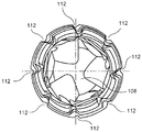
도 1 내지 도 6에 도시된 바와 같이, 본 발명의 예시적인 실시예에 따른 뼈 스크루(100)가 헤드(104)를 포함하는 근위 단부(102)로부터 긴 샤프트(106)를 따라 원위 단부(108)까지 연장된다. 예시적인 실시예에서, 헤드(104)의 외측 표면은 더 상세히 후술되는 바와 같이 뼈 고정 장치(200) 내로의 뼈 스크루(100)의 가변 각도 삽입을 허용하도록 실질적으로 구형이다. 그러나, (예컨대, 뼈 고정 장치(200) 내로의 뼈 스크루(100)의 단일-각도 삽입을 허용하기 위해) 헤드(104)가 본 발명의 범주로부터 벗어남이 없이 임의의 다른 형상으로 형성될 수 있는 것에 주목하여야 한다. 헤드(104)의 외측 표면에는, 또한 더 상세히 후술되는 바와 같이, 뼈 고정 장치(200)를 통해 연장되는 개구(202)의 벽 상에 형성된 나사형성부(212)와 로킹가능하게 맞물리도록 구성된, 일정 피치를 갖는 나사형성부(110)가 구비된다. 하나 이상의 홈(112)들이 헤드(104) 상에 제공될 수 있는데, 이때 각각의 홈(112)은 나삿니(110)들 내로 적어도 부분적으로 연장되고, 뼈 스크루(100)의 길이방향 축(114)에 대해 실질적으로 비스듬한 축을 따라 연장된다. 홈(112)들은 나삿니(110)를 단절시켜서, 특히 뼈 스크루(100)가 뼈 플레이트 구멍의 축에 대해 비스듬히 뼈 플레이트 구멍 내로 삽입될 때(즉, 헤드(104)의 나사형성부가 뼈 플레이트 구멍의 나사형성부와 오정렬될 때) 작동 구성에서 구멍(202)의 나삿니(210)들과 나삿니(110)의 정렬을 돕는 복수의 나사 스타트(thread start)들을 생성하도록 구성된다. 홈(112)들은 뼈 스크루(100)가 구동 기구(도시되지 않음)를 통해 회전될 때 뼈 내로 원위방향으로 전진하도록 추가로 허용한다.1 to 6, a
홈(112)들 각각은 예를 들어 선 B-B에 대해 대략 8.5 ± 1°의 각도로 비스듬할 수 있지만, 본 발명의 범주로부터 벗어남이 없이 임의의 다른 각도가 사용될 수 있다. 예시적인 실시예에서, 홈(112)들은 나사형성부(110)의 방향과 반대로 비스듬히 놓인다. 예를 들어, 도 1에 보인 바와 같이, 선 B-B는 나사형성부(110)의 경로에 수직이고, 홈(112)은 나사형성부(110)를 따라 그의 근위 단부(110A)로부터 원위 단부(110B)를 향해 이동할 때, 나사형성부(110)와 홈(110) 사이의 각도가 나삿니의 근위 측에서는 90° 초과이고 나삿니의 원위 측에서는 90° 미만이도록 선 B-B에 대해 비스듬히 놓인다. 다른 실시예에서, 홈(112)은 선 B-B에 대해 대략 5 내지 85°(즉, 나사형성부(110)에 대해 95° 내지 175°)의 각도로 연장된다. 또 다른 실시예에서, 홈(112)들은 선 B-B에 실질적으로 평행하게 연장될 수 있다. 이 실시예에 따른 홈(112)들은 실질적으로 나사형성부(110)의 전체 길이를 따라 연장된다. 다른 실시예(도시되지 않음)에서, 홈(112)들은 나사형성부(110)의 부분 길이에만 걸쳐 연장될 수 있다.Each of the
본 발명의 제1 예시적 실시예에서, 뼈 스크루(100)에는 도 5에 도시된 바와 같이 헤드(104) 주위에 원주방향으로 균일하게 그리고 서로 등거리로 배치되는 5개의 홈(112)들이 형성될 수 있다. 구체적으로, 이 실시예에서의 홈(112)들 각각은 인접 홈(112)들로부터 대략 72°만큼 분리된다. 다른 실시예(도시되지 않음)에서, 뼈 스크루(100)는 서로 대략 60°만큼 분리된 6개의 홈(112)들을 포함한다. 또 다른 실시예에서, 도 6에 도시된 바와 같이, 뼈 스크루(100)는 서로 대략 45°만큼 분리된 8개의 홈(112)들을 포함할 수 있다.In the first exemplary embodiment of the present invention, the bone screws 100 are formed with five
헤드(104)는 근위 단부(102)로부터 헤드 내로 연장되는 리세스(116)를 추가로 포함할 수 있다. 리세스(116)는 당업자에 의해 이해되는 바와 같이 뼈 스크루(100)에 토크를 인가하기 위한 구동 기구(도시되지 않음)의 원위 단부와의 맞물림을 허용하도록 구성된다. 도 1 내지 도 6의 실시예는 톡스형(torx-shaped) 리세스(116)를 가지고 도시되어 있다. 그러나, 당업자가 이해하는 바와 같이, 본 발명의 범주로부터 벗어남이 없이 임의의 다른 형상(예컨대, 슬롯형, 십자형, 정사각형, 육각형 등)이 채용될 수 있는 것에 주목하여야 한다.The
샤프트(106)에는 나삿니(110)들의 피치와 실질적으로 동일한 피치를 갖는 나사형성부(118)가 구비된다. 본 발명의 다른 실시예(도시되지 않음)에서, 나사형성부(118)의 피치는 나삿니(110)들의 피치보다 크거나 작을 수 있다. 샤프트(106)의 나사형성부(118)에는 당업자가 이해하는 바와 같이 2개의 리드(lead)들이 형성될 수 있다. 나사형성부(118)의 다중-리드 구성은 당업자가 이해하는 바와 같이 뼈 내로의 뼈 스크루(100)의 선형 전진을 돕는다. 당업자에 의해 이해되는 바와 같이, 샤프트(106)의 길이는 일반적으로 목표 시술의 요건에 따르도록 선택된다. 샤프트(106)의 원위 부분은 당업자가 이해하는 바와 같이 나삿니(110)들의 연속체 내에 간극을 생성하도록 그리고 뼈 스크루(100)의 자동-탭핑(self-tapping)을 허용하도록 구성되는 하나 이상의 노치(120)들을 포함할 수 있다. 샤프트(106)의 원위 부분은 예를 들어 삽입을 돕기 위해 원위 단부(106)에서 보다 작은 직경으로 테이퍼 형성될 수 있다. 원위 단부(106)는 원하는 대로 첨예화되거나 무뎌질 수 있다.The
뼈 스크루(100)는 뼈 스크루가 채용되는 뼈 고정 장치(200)의 재료보다 큰 경도를 갖도록 선택되는 재료로 형성될 수 있다. 구체적으로, 뼈 스크루(100)는 스테인레스강 및 CCM(Co-28Cr-6Mo 합금) 중 하나로 형성될 수 있다. 이때, 뼈 스크루(100)는 당업자가 이해하는 바와 같이 대략 68 HRC 이상으로 뼈 스크루의 표면 경도를 더욱 증가시키기 위해 침탄되거나 질화될 수 있다. 예시적인 실시예에서, 뼈 스크루(100)의 경도는 대략 67 내지 74 HRC, 특히 67.5 내지 70.3 HRC일 수 있다. 반면에, 뼈 고정 장치(200)는 상업용 순수 티타늄 등급 1, 2, 3 및 4, Ti-6Al-7Nb, Ti-6Al-4V, Ti-6Al-4V ELI, Ti-15Mo, CCM(Co-28Cr-6Mo 합금), 스테인레스강, 또는 뼈 스크루(100)의 재료와는 상이한 다른 재료로 형성될 수 있다. 당업자가 이해하는 바와 같이, 뼈 고정 장치(200)의 경도는 대략 75 HRB(예컨대, CP1 재료의 경우) 내지 대략 45 HRC(예컨대, CCM 재료의 경우)일 수 있다. 이러한 구성은 뼈 스크루(100)의 나삿니(110)들이 뼈 고정 장치(100) 내로 삽입될 때 나삿니들의 버링을 최소화시면서 또한 뼈 내에서의 뼈 고정 시스템의 유지 강도를 증가시킨다.The
뼈 고정 장치(100)는 임플란트 품질 오스테나이트 스테인레스강(예컨대, 316L, 22-13-5, 바이오듀어(Biodur) 108), 코발트 합금, 예를 들어 CCM (Co-28Cr-6Mo 합금), MP35N, L605, ASTM-F-1058 및 엘질로이(Elgiloy), 및 티타늄 및 그의 합금, 예를 들어 Ti-6Al-4V, Ti-6Al-7Nb 및 Ti-15Mo를 포함하지만 이로 한정되지 않는 군으로부터 선택되는 임플란트 등급 재료로 형성된다. 선택된 재료는 바람직하게는, 당업자가 이해하는 바와 같이, 신체 내에서 파편화되어 남는 경우에, 환자가 부작용을 겪음이 없이 자기 공명 영상("MRI")을 받을 수 있도록 비-자성이다. 또한, 선택된 재료의 침탄/질화 처리는 첨예한 에지를 포함하지 않는 파편화된 부분들을 생성하여, 주위 조직의 외상을 방지한다. 뼈 고정 장치(100)의 선택된 재료가 종래의 장치에 비해 실질적으로 연질이지만, 침탄되거나 질화된 외측 표면의 추가는 뼈 고정 장치가 내부에 채용되는 뼈의 강성보다 더 크고 종래의 뼈 고정 장치보다 실질적으로 더 큰 수준으로 뼈 고정 장치의 강성을 증가시킨다. 구체적으로, 뼈 고정 장치(100)는 당업자가 이해하는 바와 같이 대략 68 HRC 이상의 표면 경도를 가질 수 있다. 예시적인 실시예에서, 뼈 고정 장치(100)의 경도는 대략 67 내지 74 HRC, 특히 67.5 내지 70.3 HRC일 수 있다. 당업자가 이해하는 바와 같이, 이러한 구성은 장기간의 사용 후에 나사형성부(110, 118)의 무뎌짐을 최소화하면서 또한 예시적인 리밍 절차에 따라 뼈 내로의 뼈 고정 장치(100)의 삽입을 용이하게 한다. 수술 동안에, 뼈 고정 장치(100)의 침탄되거나 질화된 외측 표면은 첨예화의 상실 또는 시징(seizing) 없이 뼈 및/또는 금속을 통해 절삭하는 것을 돕는다. 뼈 고정 장치(100)의 예시적인 침탄되거나 질화된 외측 표면은 과도한 버링 또는 상기 버링으로 인한 교체의 정당화라는 위험 없이 뼈 내에서의 뼈 고정 장치의 사용을 허용한다. 또한, 본 발명의 침탄되거나 질화된 재료는 장치의 기하학적 구조를 확대시키거나 달리 변화시킬 필요 없이 뼈 고정 장치에 증가된 강성을 제공한다.The
일 실시예에서, 뼈 고정 장치는 본질적으로 니켈이 없는 오스테나이트 스테인레스 합금인 바이오듀어 108 합금으로 형성될 수 있다. 이러한 합금은 그의 오스테나이트 구조를 유지하기 위해 높은 질소 함량을 함유한다. 그 결과, 바이오듀어 108 합금은, 타입 316L(ASTM F138), 22Cr-13Ni-5Mn 합금(ASTM F1314), 및 734 합금(ASTM F1586)과 같은 니켈-함유 합금에 비해 개선된 수준의 인장 및 피로 강도를 갖는다. 피팅(pitting) 및 틈 부식(crevice corrosion)에 대한 바이오듀어 108 합금의 내성은 타입 316L 합금보다 우수하고, 22Cr-13Ni-5Mn 및 734 합금과 동등하다. 바이오듀어 108 합금은 그의 미세구조 완전성 및 청결도를 보장하기 위해 전기-슬래그 재용해(Electro-Slag Remelting, ESR) 공정에 의해 생성된다. 이 합금은 비-자성이고, 본질적으로 페라이트 상이 없다. 바이오듀어 108 합금은 그의 높은 수준의 크롬 및 질소와 그의 몰리브덴 함량으로 인해 높은 내식성을 갖는다. 이 합금은 피팅 및 틈 부식에 대한 우수한 내성을 나타낸다. 바이오듀어 108 합금은 니켈-함유 합금, 22Cr-13Ni-5Mn(ASTM F1314) 및 734(ASTM F1586)와 동등하거나 그보다 큰 내식성을 갖도록 설계되었다. 이들 합금의 내식성 수준은 타입 316L 합금(ASTM F138)보다 우수하다. 바이오듀어 108 합금 시편에서 50℉(10℃)의 임계 틈 부식 온도가 (ASTM G48, 방법 D에 따라) 측정되었다. 22Cr-13Ni-5Mn 합금의 동일하게 준비된 시편들에서 41℉(5℃)의 임계 온도가 측정되었다. 이들 시험 조건 하에서, 타입 316L 합금의 임계 온도는 32℉(0℃) 아래일 것이다. 바이오듀어 108 합금과 비교 합금의 상대적인 내식성이 98.6℉(37℃)의 링거액(Ringer's solution)에서 양극 분극(anodic polarization) 시험을 이용하여 확인되었다. 바이오듀어 108 합금 시험 물품은 세포 무독성, 무독성, 비-용혈성, 무시해도 될 정도의 자극성인 것으로 결론지어졌고, 독성의 징후가 관찰되지 않았음을 나타내며; 시험 물품은 ISO 10993-11의 요건을 충족시키는 것으로 결론지어졌고, 발열원을 함유하지 않으며, 채용된 방법에 기초하여 비-돌연변이 유발성이다.In one embodiment, the bone fixation device may be formed of a
본 발명에 따른 예시적인 재료가, 다른 처리 방법과는 대조적으로 탄화물의 형성을 최소화시키는 저온 침탄을 사용하여, 처리된다. 그 개시 내용 전체가 본 명세서에 참고로 포함되는, 발명의 명칭이 "저온 표면 경화 공정(Low Temperature Case Hardening Process)"인 미국 특허 제6,464,448호가 산업용 부품 및 조립체를 위한 철계 재료의 저온 침탄을 기술하고 있다. 이들 공정은, 아마도 산업적 환경에서는 문제가 없지만 신체 내에 배치될 때 재료를 부식에 취약하게 하는 표면 결함의 존재로 인해, 이전에는 임플란트 등급 의료 장치 또는 임플란트에 적용되지 않았다. 본 출원은 외과용 기기에 사용하기에 충분한 내식성 재료를 제공하기 위해 강 또는 다른 재료의 저온 침탄을 적용한다. 즉, 본 발명에 따른 예시적인 시스템과 방법은, 예를 들어 산화물을 형성하는 데 이용 가능한 대신에 탄화물에 대한 크롬의 결합에 의해 부분적으로 부식이 야기될 수 있는 당업계에 알려진 다른 재료에 비해, 증가된 내식성을 갖는 장치를 형성하도록 페라이트가 없는 임플란트 등급 재료를 침탄/질화시키는 새로운 기술을 적응시킨다. 본 발명에 따른 재료 내의 보다 높은 수준의 몰리브덴은 재료의 내식성을 더욱 증가시킨다. 당업자가 이해하는 바와 같이, 본 명세서에 기술된 장치들 중 임의의 것을 형성하기 위해 어닐링과 냉간-가공의 조합이 사용될 수 있다. 생성된 재료는 탄소가 침입형 탄소(interstitial carbon)의 형태로 매트릭스를 과포화시킨 확산 구역을 포함한다. 이러한 과포화의 효과는 개선된 경도, 내마모성 및 내식성이다. 본 발명의 예시적인 재료는 더 상세히 후술된다.Exemplary materials according to the present invention are treated using low temperature carburization, which minimizes the formation of carbides, in contrast to other processing methods. U.S. Patent No. 6,464,448 entitled " Low Temperature Case Hardening Process ", the entirety of which is incorporated herein by reference, describes low temperature carburization of iron-based materials for industrial components and assemblies have. These processes have not previously been applied to implant grade medical devices or implants due to the presence of surface defects which are probably not problematic in an industrial environment but which, when placed in the body, make the material vulnerable to corrosion. The present application applies low temperature carburization of steel or other materials to provide a corrosion resistant material that is sufficient for use in surgical devices. That is, the exemplary systems and methods according to the present invention are particularly advantageous over other materials known in the art, which can be partially corroded by the bonding of chromium to carbides instead of, for example, Adapted a new technique of carburizing / nitriding ferrite-free implant grade materials to form devices with increased corrosion resistance. A higher level of molybdenum in the material according to the invention further increases the corrosion resistance of the material. As those skilled in the art will appreciate, a combination of annealing and cold-working can be used to form any of the devices described herein. The resulting material includes a diffusion zone in which the matrix is supersaturated with carbon in the form of interstitial carbon. The effect of such supersaturation is improved hardness, abrasion resistance and corrosion resistance. Exemplary materials of the present invention are described in further detail below.
당업자가 이해하는 바와 같이, 철의 3가지 주 입방 형태들, 즉 오스테나이트(FCC), 마르텐사이트(BCT) 및 페라이트(BCC)가 존재한다. 마르텐사이트 및 페라이트 둘 모두는 자성인 반면, 오스테나이트는 그렇지 않다. 따라서, 종래의 임플란트 품질 316L 스테인레스강은 주조된 그대로의 상태에서도 완전히 오스테나이트계이도록 의도적으로 평형이 맞추어져, MRI 자기장과 의료 장치의 상호작용을 최소화하거나 제거한다. 이는 주조된 그대로의 평형이 오스테나이트 영역 내에 있는 것을 보장하는 방식으로 오스테나이트 안정화 원소와 페라이트 안정화 원소의 평형을 맞춤으로써 수행된다. 소정 원소가 오스테나이트 또는 페라이트를 안정화시킨다는 것이 잘 알려져 있다. 몰리브덴 및 크롬과 같은 페라이트 안정화 원소들 중 많은 것이 또한 내식성을 증진시키기 때문에, 이들은 오스테나이트 형성 원소를 증가시킴으로써 평형이 맞추어지거나, 합금은 오스테나이트와 함께 페라이트를 함유할 것이다. 규격 범위가 과도하게 넓은 것으로 보일 수 있다. 그러나, 소정의 상 평형을 생성할 필요성을 비용을 최소화시키면서 내식성을 최대화시킬 필요성과 평형을 맞출 때, 실제 화학적 성질이 규격이 암시하는 것보다 훨씬 더 작은 범위 내에서 변할 것임이 명백하게 된다. 316L의 종래의 산업용 버전에서, 페라이트가 용접부에서의 고온 균열을 감소시키는 것으로 알려져 있기 때문에, 합금의 용접 특성을 개선하기 위해 소정량의 페라이트가 합금 내에 의도적으로 존재한다. 제강업자에 대해, 이는 용해 및 주조 동안에, 특히 연속 주조 동안에 고온 균열의 유사한 감소를 제공한다. 전형적인 상업용 316L 재료는 작은 백분율의 페라이트와 함께 대부분의 오스테나이트를 함유하는 합금이다. 이는 주조된 그대로의 상태에서 그리고 또한 바아, 와이어, 시트 및 판과 같은 완성된 그대로의 가공 제품에서 그러하다.As will be appreciated by those skilled in the art, there are three main cubic forms of iron, austenite (FCC), martensite (BCT) and ferrite (BCC). Both martensite and ferrite are magnetic, whereas austenite is not. Thus, conventional implant quality 316L stainless steel is intentionally balanced to be fully austenitic, as-cast, minimizing or eliminating the interaction of the MRI magnetic field with the medical device. This is accomplished by balancing the austenite stabilizing element and the ferrite stabilizing element in such a manner as to ensure that the cast as-is equilibrium is within the austenite region. It is well known that certain elements stabilize austenite or ferrite. Since many of the ferrite stabilizing elements such as molybdenum and chromium also enhance corrosion resistance, they may be equilibrated by increasing the austenite forming element, or the alloy may contain ferrite with austenite. The standard range may seem to be excessively wide. However, when balancing the need to create a given phase balance with the need to maximize corrosion resistance while minimizing costs, it becomes clear that the actual chemical properties will vary within a much smaller range than the specification suggests. In the conventional industrial version of the 316L, a certain amount of ferrite is intentionally present in the alloy to improve the welding characteristics of the alloy, since ferrite is known to reduce hot cracking at the weld. For the steelmaker, this provides a similar reduction of hot cracks during melting and casting, especially during continuous casting. A typical commercial 316L material is an alloy containing most of the austenite with a small percentage of ferrite. This is true in the state of being cast and also in finished products such as bars, wires, sheets and plates.
한편, 임플란트 품질 316L은 페라이트가 합금 내에 존재하지 않도록 화학적으로 평형이 맞추어진다. ASTM F 138과 같은 규격에서 주어지는 화학적 범위가 페라이트를 생성할 수 있지만, 이러한 규격은 최종 제품이 페라이트를 함유하지 않을 것을 요구한다. 이를 달성하기 위해, 제조자는 실제 화학적 성질을 100% 오스테나이트 영역 내로 평형을 맞춘다. 스테인레스강에서 오스테나이트-페라이트 평형을 예측하기 위한 많은 방법들이 있다. 가장 흔한 방법들 중 2가지는 셰플러 다이어그램 및 WRC-1992 다이어그램이다. 이들 기술 각각에서, 크롬 당량, 니켈 당량 및 상 평형 사이에서 상관관계가 이루어졌다. 크롬 및 니켈 당량들은, 크롬 및 니켈의 기본 원소에 관하여, 존재하는 페라이트 또는 오스테나이트 형성 원소들의 총량을 이들의 안정화 효과와 관련시킨다. 침탄은 20 μm 내지 35 μm 정도의 두께인 장치의 외부 표면 층 부근의 작은 영역만이 침탄되는 확산 제어식 공정이다. 페라이트 그레인(grain)이 이 영역 내에 존재하는 상태로 유지되면, 이는 침탄되지 않아, 침탄된 층만큼 내식성이지 않을 비침탄된 영역을 형성할 것이다. 이들 영역에서 부식 터널링 효과가 발생하여, 부식이 물품의 중심부로 침투하게 하여서, 잠재적으로 파국적 고장(catastrophic failure)을 초래할 수 있다.On the other hand, the implant quality of 316L is chemically balanced so that ferrite is not present in the alloy. Although the chemical range given in the same specification as ASTM F 138 can produce ferrite, this specification requires that the final product does not contain ferrite. To achieve this, the manufacturer equilibrates the actual chemical properties into the 100% austenite region. There are many ways to predict austenite-ferrite equilibrium in stainless steels. Two of the most common methods are the Schaeffler diagram and the WRC-1992 diagram. In each of these techniques, a correlation was made between chromium equivalents, nickel equivalents and phase equilibria. The chromium and nickel equivalents relate the total amount of ferrite or austenite forming elements present, with respect to the basic elements of chromium and nickel, to their stabilizing effect. Carburizing is a diffusion controlled process in which only a small area near the outer surface layer of a device with a thickness of about 20 μm to 35 μm is carburized. If ferrite grains remain in this region, it will not be carburized and will form a non-carburized region that is not as corrosion resistant as the carburized layer. Corrosion tunneling effects occur in these areas, causing corrosion to penetrate into the core of the article, potentially resulting in catastrophic failure.
본 발명에 따른 예시적인 재료는 임플란트 품질 316L이 어떠한 페라이트도 함유하지 않기 때문에 침탄을 위해 이를 이용하여서, 침탄된 층을 방해하는 페라이트 입자의 존재의 위험을 완화시킨다. 페라이트를 형성하는 경향을 보여주기 위해, 하기의 것이 비교되었다: (1) ASTM F138, ASTM F 139 및 ISO 5832-1의 요건들을 만족시키는, 신쎄스(Synthes)에서 얻어진 임플란트 품질 316L. 샘플 크기 - 1366개 샘플들, 및 (2) ASTM A 276의 요건에 따라 공급자에 의해 제조된 산업용 품질 316L. 샘플 크기 - 3,556개 샘플들. 하기의 표에 나타낸 바와 같이, 셰플러 방법 및 WRC-1992 방법을 사용하여 페라이트 함량을 결정하기 위해 각각의 평균 화학적 성질이 플로팅(plotting)되었다:Exemplary materials in accordance with the present invention utilize it for carburizing because the implant quality 316L contains no ferrite, thereby mitigating the risk of the presence of ferrite particles interfering with the carburized layer. To demonstrate the tendency to form ferrites, the following were compared: (1) Implant quality of 316L obtained from Synthes, meeting the requirements of ASTM F138, ASTM F 139 and ISO 5832-1. Sample size - 1366 samples, and (2) industrial quality 316L manufactured by the supplier in accordance with the requirements of ASTM A 276. Sample size - 3,556 samples. As shown in the table below, the average chemical properties of each were plotted in order to determine the ferrite content using the Schaeffler method and the WRC-1992 method:


도 11 내지 도 18에 도시된 바와 같이, 위에 개시된 재료들의 비교는 임플란트 품질 316L이 100% 오스테나이트 영역 내로 평형이 맞추어지는 반면, 산업용 품질 316L이 대략 7 내지 8% 페라이트에서 평형이 맞추어진다는 것을 보여준다. 이 기술들 각각은 또한 규격 범위에 기초하여 가능한 % 페라이트 대역을 보여준다. 구체적으로, 도 12는 도 11의 다양한 유형의 종래의 산업용 강도 미세구조체들의 용접 특성에 관한 정보를 미세구조체들이 함유하는 합금 원소들의 함수로서 제공한다. 도 12의 차트는 하기의 재료 조성들에 대한 표준 분석의 범위에 대한 셰플러 다이어그램에 해당한다. 도 14는 도 13의 다양한 유형의 종래의 산업용 강도 미세구조체들의 용접 특성에 관한 정보를 미세구조체들이 함유하는 합금 원소들의 함수로서 제공한다. 도 14의 차트는 하기의 재료 조성들에 대한 표준 분석의 범위에 대한 WRC-1992 다이어그램에 해당한다. 도 15 내지 도 18은 본 발명에 따른 예시적인 임플란트 등급 재료에 대한 동일한 데이터를 제공하는데, 여기서 도 16은 도 15의 데이터의 셰플러 다이어그램에 해당하고, 도 18은 도 17의 데이터의 WRC-1992에 해당한다. 상기에 비추어, 본 발명에 따른 예시적인 재료가 100% 오스테나이트 영역 내에서 평형이 맞추어지는 임플란트 등급 재료를 제공하여, 종래의 재료에서 흔히 생성되는 페라이트를 제거한다는 것이 명백하다.As shown in Figs. 11-18, a comparison of the materials disclosed above shows that 316L of implant quality is balanced within a 100% austenite region, whereas industrial quality 316L is equilibrated at approximately 7-8% ferrite Show. Each of these techniques also shows the possible% ferrite band based on the specification range. Specifically, Figure 12 provides information about the welding characteristics of the various types of conventional industrial strength microstructures of Figure 11 as a function of the alloying elements contained in the microstructures. The chart of Figure 12 corresponds to the Schaeffler diagram for the range of standard analyzes for the following material compositions. Figure 14 provides information about the welding characteristics of the various types of conventional industrial strength microstructures of Figure 13 as a function of the alloying elements contained in the microstructures. The chart of Figure 14 corresponds to the WRC-1992 diagram for the scope of the standard analysis for the following material compositions. 15 through 18 provide the same data for an exemplary implant grade material according to the present invention, where FIG. 16 corresponds to the Schaeffler diagram of the data of FIG. 15, and FIG. 18 corresponds to WRC-1992 of the data of FIG. . In view of the above, it is clear that the exemplary material according to the present invention provides an implant grade material that is balanced within the 100% austenite region to remove the ferrite that is often produced in conventional materials.
본 명세서에 기술된 예시적인 구성이 뼈 스크루와 같은 뼈 고정 장치(100)에 관한 것이지만, 본 발명의 개념은 본 발명의 범주로부터 벗어남이 없이 임의의 다른 뼈 고정 장치/임플란트에 채용될 수 있다. 그러한 뼈 고정 장치는 뼈 핀(pin), 버트레스(buttress) 핀, 뼈 플레이트, 골수내 못(intramedullary nail), 전자(trochanteric) 못 등을 포함하지만 이로 한정되지 않는다.Although the exemplary configuration described herein is directed to a
도 7 내지 도 10은 본 발명에 따른 예시적인 뼈 고정 장치(200)를 도시한다. 도시된 장치(200)가 뼈 플레이트이지만, 본 발명의 범주로부터 벗어남이 없이 임의의 다른 뼈 고정 장치(예컨대, 골수내 못 등)가 사용될 수 있다는 것이 제안된다. 뼈 플레이트(200)는 예를 들어 몸체(204)를 통해 연장되는 8개의 구멍(202)들을 포함하는 4.5 mm 폭의 가변 각도 압박 플레이트일 수 있다. 구멍(202)들 중 임의의 것 또는 모두가 제1 가변 각도 구멍 부분(206), 및 제1 구멍 부분으로 개방되어 있는 제2 압박 구멍 부분(208)을 포함하는 가변 각도 조합형 구멍들로서 형성될 수 있다. 제1 구멍 부분(206)은 제1 표면(203)에 인접하게 형성되는 제1 릴리프 절결부(relief cut)(210), 이로부터 원위방향으로 연장되는 제2 원통형 나사형성된 부분(212), 및 작동 구성에서 뼈와 접촉하도록 구성되는 제2 표면(205)에 인접하게 형성되는 제3 릴리프 절결부(214)를 포함할 수 있다. 릴리프 절결부(210)는 구멍(202)의 길이방향 축에 대해 대략 15°의 각도로 연장될 수 있지만, 본 발명의 범주로부터 벗어남이 없이 다른 각도들이 사용될 수 있다. 제1 구멍 부분(206)은 그의 외측 벽 상에 제공되는 하나 이상의 슬롯(207)들을 추가로 포함하는데, 이때 슬롯(207)들은 스크루 구멍 축에 실질적으로 수직하게 연장된다. 당업자가 이해하는 바와 같이, 슬롯(207)은 뼈 스크루(100)와 나사형성된 부분(212)의 정렬을 돕는 다수의 나사 스타트들을 제공하기 위해 나사형성된 부분(212)의 나삿니들을 단절시킨다. 제2 구멍 부분(208)은 제1 테이퍼형 구멍 부분(216) 및 이로부터 원위방향으로 연장되는 제2 테이퍼형 구멍 부분(218)을 포함할 수 있다. 뼈 고정 장치(200)가 8개의 구멍들을 갖고서 도시되어 있지만, 본 발명의 범주로부터 벗어남이 없이 임의의 다른 개수의 구멍들이 사용될 수 있고, 이들 구멍이 임의의 다양한 알려진 뼈 스크루 장착 구멍들을 포함할 수 있는 것에 주목한다. 뼈 고정 장치(200)는 또한 본 발명의 범주로부터 벗어남이 없이 임의의 개수와 조합의 가변 각도 구멍들, 단일 구멍들 및 조합형 구멍들을 포함할 수 있다. 제2 표면(205)은, 당업자가 이해하는 바와 같이, 예를 들어 이식 후 혈액 공급의 장애를 감소시키기 위해 뼈 고정 장치(200)와 뼈 사이의 접촉 표면적을 감소시키도록 구성되는 복수의 언더컷(undercut)(220)들을 추가로 포함할 수 있다.Figures 7 to 10 illustrate an exemplary
작동 구성에서, 뼈 스크루(100)는 뼈 고정 장치(200)를 통해 뼈 내로 삽입된다. 당업자가 이해하는 바와 같이, 의사 또는 다른 사용자가 특정 시술의 요건에 따르도록 원하는 삽입 각도를 선택할 수 있다. 헤드(104) 상에 제공된 홈(112)들 및 구멍(202) 내에 제공된 슬롯(207)들에 의해 제공되는 다수의 나삿니 스타트들은 구멍(202)의 나사형성된 부분(212)과 헤드의 나삿니(110)들의 정렬을 돕는다. 뼈 스크루(100)가 뼈 고정 장치(200)를 통해 뼈 내로 나사 조임될 때, 뼈 스크루(100)의 침탄되거나 질화된 외측 표면은 나삿니(110)들의 버링을 최소화시킨다. 뼈 고정 장치(200)에 비해 뼈 스크루(100)의 증가된 강성은 또한 뼈 스크루의 버링을 초래함이 없이 (예컨대, 뼈 내에서의 뼈 스크루의 위치를 보정하기 위한) 뼈 스크루(100)의 제거 및 뼈 내로의 재삽입을 허용한다.In an operational configuration, the
본 발명에 따른 예시적인 침탄되거나 질화된 외측 표면은 뼈 스크루(100)로 제한되지 않는다. 다른 실시예에서, 침탄되거나 질화된 외측 표면 및 페라이트 없는 구성은 가변 각도 뼈 스크루, 로킹 스크루, 압박 스크루 또는 당업계에 알려진 임의의 다른 뼈 스크루를 포함하지만 이로 한정되지 않는 임의의 종래의 뼈 스크루에 적용될 수 있다. 예시적인 뼈 스크루는 헤드(104) 상에 홈(112)이 없이 형성될 수 있다. 헤드(104)의 외측 프로파일은 테이퍼형, 둥근형, 구형 및 원통형 중 하나일 수 있다.Exemplary carburized or nitrated outer surfaces according to the present invention are not limited to bone screws 100. In other embodiments, the carburized or nitrated outer surface and the ferrite-free configuration may be applied to any conventional bone screw including, but not limited to, variable angle bone screws, locking screws, compression screws or any other bone screws known in the art. Can be applied. An exemplary bone screw may be formed without a
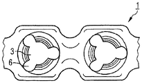
일 실시예서, 뼈 스크루는 그 개시 내용 전체가 본 명세서에 참고로 포함된, 발명의 명칭이 "뼈 플레이트(Bone Plate)"인 미국 특허 제8,343,196호에 개시된 뼈 스크루(10)와 유사하게 형성될 수 있다. 구체적으로, 도 19와 도 21에 도시된 바와 같이, 뼈 플레이트(1)는 뼈 플레이트의 뼈-접촉 측의 저면(2), 상부면(8), 및 저면(2)을 상부 면(8)과 연결하는, 플레이트 내의 복수의 구멍(3)들을 구비하며, 이때 구멍들은 중심 구멍 축(5)을 갖는다. 플레이트 내의 구멍(3)들은 저면(2)을 향해 테이퍼형으로 된 내부 재킷 표면(4)을 구비한다. 또한, 내부 재킷 표면(4)은 서로로부터 120도의 균일한 거리를 두고 구멍의 구멍 축(5)으로부터 반경방향으로 멀리 연장되는 3개의 리세스(6)들을 구비한다. 리세스들의 주연부 확장은 대략 40도이고, 이들은 전적으로 내부 재킷 표면(4) 내에서 연장된다. 리세스(6)들은 상부 면(8)으로부터 저면(2)까지 뼈 플레이트(1)의 전체 높이에 걸쳐 테이퍼형으로 연장된다. 게다가, 내부 재킷 표면(4)에는 나삿니 형태의 3차원 구조체(7)가 구비된다.In one embodiment, the bone screw is formed similar to the
도 22는 리세스들이 구멍의 축으로부터 반경방향으로 멀리 내부 재킷 표면을 지나 연장되는, 도 21에 따른 실시예의 변형을 도시한다.Figure 22 shows a variation of the embodiment according to Figure 21, wherein the recesses extend radially farther from the axis of the hole through the inner jacket surface.
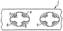
도 20과 도 23은 플레이트 내의 구멍(3)들이 타원형 구멍들로서 구성되는, 추가의 대안적인 실시예를 도시한다. 뼈 플레이트는 기본적으로 플라스틱 재료(PEEK)로 제조되는데, 이때 티타늄제의 매립된 금속 나삿니 삽입체(9)들이 플레이트 내의 구멍(3)들을 형성한다. 이러한 실시예의 경우에, 플레이트 내의 구멍(3)은 구멍의 축(5)으로부터 반경방향으로 멀리 내부 재킷 표면(4)을 지나 연장되는 4개의 리세스(6)들을 구비한다. 내부 재킷 표면(4)은 재킷 표면의 4개의 섹션들로 분할된다. 리세스들은 상부 면(8)으로부터 저면(2)까지 뼈 플레이트(1)의 전체 높이에 걸쳐 테이퍼형으로 연장된다. 게다가, 내부 재킷 표면(4)에는 다중-스타트 나삿니 형태의 3차원 구조체(7)가 구비된다. 재료에 관한 한, 이 실시예는 또한 반대로 될 수 있음으로써, 뼈 플레이트가 기본적으로 금속(티타늄)으로 제조되고, 뼈 플레이트 내에 매립되는 나삿니 삽입체(9)들이 플라스틱 재료(PEEK)로 제조되어 플레이트 내의 구멍(3)들을 형성한다. 뼈 플레이트(1)는 대안적으로, 이전 실시예에 관하여 더 상세히 기술된 바와 같은 경도를 나타내는 당업계에 알려진 임의의 다른 재료로 형성될 수 있다. 뼈 스크루(10)는, 또한 이전에 더 상세히 기술된 바와 같이, 침탄되거나 질화된 외측 표면을 갖는 페라이트 없는 생체적합성 재료로 형성될 수 있다.20 and 23 illustrate a further alternative embodiment in which the
도 24는 그 헤드 부분(11)들이 구형인 뼈 스크루(10)들이 삽입된 도 19에 따른 뼈 플레이트를 위로부터 도시한다. 도 25는 동일한 뼈 플레이트(1)를 아래로부터 도시한다.Fig. 24 shows a bone plate according to Fig. 19 from above, in which the
도 26에서, 뼈 스크루(10)가 각도 오정렬 없이 내부에 삽입된 뼈 플레이트(1)가 도시되어 있다. 뼈 플레이트(1)의 구멍의 내부 재킷 표면(4)과 뼈 스크루(10)의 헤드 부분(11)은 정합하는 나삿니(13)들을 구비한다. 도 27은 도 26과 동일한 변형을 도시하지만, 뼈 스크루(10)가 각도 오정렬되어 있다.26, a
다른 실시예에서, 뼈 스크루는 그 개시 내용이 또한 본 명세서에 포함된 미국 특허출원 공개 제2008/0140130호의 뼈 스크루(100, 200, 300, 500, 600, 702, 1360, 14100, 14200, 31200)와 유사할 수 있다. 구체적으로, 도 28은 피질(cortex) 스크루로서 또한 알려진 전형적인 비-로킹 뼈 스크루(150)를 도시한다. 일반적으로, 대체로 매끄러운 표면을 갖는 비-나사형성된 헤드(152)를 구비하고 선택된 플레이트 구멍에 적합한 크기 및 기하학적 형상을 구비하는 임의의 외과용 뼈 스크루가 예시적인 재료로 형성될 수 있고 본 발명에 따른 침탄되거나 질화된 외측 표면이 형성될 수 있다. 헤드(152)의 형상은, 예를 들어 원추형의 테이퍼 형상, 곧은-면 형상, 구형, 반구형 등일 수 있다. 비-로킹 스크루(150)는 뼈에 대한 부착을 위해 적어도 부분적으로 나사형성된 샤프트(154)를 구비한다. 샤프트(154)의 길이와 샤프트 나삿니(157)의 나삿니 구성(예컨대, 피치, 프로파일 등)은 응용에 따라 변할 수 있다. 당업계에 알려져 있는 바와 같이, 팁(156)과 샤프트 나삿니(157)는 뼈 내로의 이식을 용이하게 하기 위해 자동-탭핑 및/또는 자동-드릴링식일 수 있다. 헤드(152)와 샤프트(154)는 또한 적당한 배치를 돕기 위해 안내 와이어를 수용하기 위한 캐뉼러(cannula)(158)를 구비할 수 있다.In another embodiment, the bone screw is formed from
도 29는 전형적인 로킹 스크루(160)를 도시한다. 일반적으로, 나사형성된 헤드(162)를 갖는 임의의 외과용 뼈 스크루가, 헤드(162)가 선택된 플레이트 구멍에 적합한 크기 및 기하학적 형상을 갖고 나삿니(163)들이 플레이트 구멍 내의 나삿니 세그먼트들의 컬럼들과 정합하면, 본 발명에 사용될 수 있다. 헤드(162)의 형상은 전형적으로 원추형의 테이퍼 형상이지만, 또한 예를 들어 곧은-면 형상일 수 있다. 로킹 스크루(160)는 뼈에 대한 부착을 위해 적어도 부분적으로 나사형성된 샤프트(164)를 구비한다. 샤프트(164)의 길이와 샤프트 나삿니(167)의 나삿니 구성(예컨대, 피치, 프로파일 등)은 응용에 따라 변할 수 있다. 당업계에 알려져 있는 바와 같이, 팁(166)과 샤프트 나삿니(167)는 뼈 내로의 이식을 용이하게 하기 위해 자동-탭핑 및/또는 자동-드릴링식일 수 있다. 헤드(162)와 샤프트(164)는 또한 적당한 배치를 돕기 위해 안내 와이어를 수용하기 위한 캐뉼러일 수 있다.FIG. 29 shows a
도 30과 도 31은 전형적인 로킹 스크루(300)의 헤드(302)를 도시한다. 헤드(302) 상의 나삿니(303)의 프로파일은 플랭크(flank)(311)들에 의해 연결되는 나사 산(peak)(310)들 및 나사 골(trough)(312)들을 포함하는데, 이때 도 32에 도시된 바와 같이 2개의 인접한 플랭크(311)들이 나삿니 각도(317)를 형성한다. 알려진 로킹 스크루에서 일반적인 바와 같이 원추형으로 형상화되는 헤드(302)는, 전형적으로 나사 산(310)이 선(313 또는 315)과 같은 직선 상에 놓이고 나사 골(312)이 선(314 또는 316)과 같은 다른 직선 상에 놓이도록 배향되며, 여기서 선의 쌍(313, 314 및 315, 316)은 서로 평행하다. 또한, 각각의 나사 산(310) 및 각각의 나사 골(312)의 나삿니 프로파일 선들은, 도 31에 도시된 골 프로파일 선(318a 내지 318e)들에 의해 표현되는 바와 같이 서로 평행하게 그리고 스크루의 중심축(319)에 직각 또는 수직으로 연장된다. 프로파일 선(318a 내지 318e)들은 나삿니 커터의 절삭 비트(305)가 헤드(302)의 외측 표면과 접촉하여 나삿니(303)를 절삭할 때 절삭 비트의 길이방향 축(301)을 연장시킴으로써 형성된다. 전형적인 로킹 스크루는 또한 중심축(예컨대, 319)을 따라 측정될 때 일정한 나사 피치(산들 사이의, 골들 사이의, 또는 프로파일 선들 사이의 거리)를 갖는다.Figures 30 and 31 show the
본 발명에 따른 가변-각도 로킹 스크루는 적어도 부분적으로 구형인 스크루헤드를 구비한다. 헤드의 구형 부분은 그의 외측 표면 상에 바람직하게는 이중 리드 나삿니인 나삿니를 구비한다. 나삿니는 헤드의 구형 부분의 원호형(즉, 비-선형) 곡률 반경을 따르는 프로파일을 갖는다. 나사 피치가 곡률 반경을 따라 측정될 때 일정하지만, 헤드의 구형 부분의 일 단부(예컨대, 상부)로부터 다른 단부(예컨대, 기저부)까지 스크루의 중심축을 따라 측정될 때 좁게-넓게-좁게 변하는 것에 주목한다(예컨대, 도 57 내지 도 60 그리고 추가로 아래에서의 이들의 설명을 참조). 이러한 나삿니 프로파일은 가변-각도 로킹 스크루가 소정 각도 범위 내의 선택가능한 각도로 본 발명의 뼈 플레이트 구멍과 맞물리게 하면서, 유리하게는 선택된 각도에 상관없이 뼈 플레이트와의 동일한 정도의 접촉을 유지한다. 즉, 허용가능한 각도 범위 내의 뼈 플레이트 구멍의 중심축에 대한 스크루의 각도는 플레이트 구멍의 내측 표면에 대한 스크루헤드 나삿니의 맞물림에 영향을 미치지 않는다. 스크루헤드의 구형 부분 상의 나삿니들이 나삿니 세그먼트들의 컬럼들과 정확하게 동일한 방식으로 맞물려 양호한 맞춤을 보장하기 때문에, 유리하게는 스크루가 뼈 플레이트 구멍 내로 삽입되는 (소정 각도 범위 내의) 각도에 상관없이 스크루와 뼈 플레이트 사이에 밀착 로크(tight lock)가 얻어진다.The variable-angle locking screw according to the present invention has an at least partially spherical screw head. The spherical portion of the head preferably has a double lead threaded thread on its outer surface. The threads have a profile along an arcuate (i.e., non-linear) radius of curvature of the spherical portion of the head. It is noted that while the thread pitch is constant as measured along the radius of curvature, it varies narrowly-wide-narrow as measured along the central axis of the screw from one end (e.g., top) of the spherical portion of the head to the other end (See, for example, Figs. 57 to 60 and further explanations thereof below). Such a threaded profile advantageously maintains the same degree of contact with the bone plate, regardless of the angle selected, while the variable-angle locking screw engages the bone plate apertures of the present invention at selectable angles within a certain angular range. That is, the angle of the screw with respect to the central axis of the bone plate hole within the allowable angular range does not affect the engagement of the screw head thread with respect to the inner surface of the plate hole. Because the threads on the spherical portion of the screw head ensure a good fit with the columns of threaded segments in exactly the same way, advantageously, the screw and bone (s) A tight lock is obtained between the plates.
도 33 내지 도 35는 본 발명에 따른 가변-각도 로킹 스크루의 일 실시예를 도시한다. 가변-각도 로킹 스크루(500)는 부분-구형 헤드(502)와 샤프트(504)를 구비한다. 헤드(502)는 나삿니(503)를 구비하고, 샤프트(504)는 나삿니(507)를 구비한다. 헤드(502)는 바람직하게는 스크루를 뼈 내외로 그리고 뼈 플레이트 구멍 내외로 구동 및 추출하기 위한 공구를 수용하기 위한 리세스(509)를 구비한다. 바람직하게는, 팁(506)과 샤프트 나삿니(507)는 뼈 내로의 이식을 용이하게 하기 위해 자동-탭핑 및/또는 자동-드릴링식이다. 헤드(502)와 샤프트(504)는 적당한 배치를 돕기 위해 안내 와이어를 수용하기 위한 캐뉼러일 수 있다. 도 34와 도 35는 유리하게는 곡률 반경(525)을 따르는 나삿니(503)의 프로파일을 도시한다. 일 실시예에서, 반경은 약 2 mm이다. 프로파일에 보인 바와 같이 나삿니(503)의 각자의 산(510)들 및 골(512)들은 바람직하게는 동일한 각도 증분들만큼 분리된다. 산(510)들 및 골(512)들은, 이 실시예에서 바람직하게는 약 60도인 나삿니 각도(517)로 플랭크(511)들에 의해 연결된다. 나삿니 프로파일 선(518a 내지 518f)들은 골(512)들을 통해 연장되고, 곡률 반경(525)의 중심(526)과 교차하는 일련의 선들을 초래한다. 프로파일 선(518a 내지 518f)들은 나삿니 커터의 절삭 비트(505)가 헤드(502)의 외측 구형 표면과 접촉하여 나삿니(503)를 절삭할 때 절삭 비트의 길이방향 축(501)을 연장시킴으로써 형성된다. 이 실시예에서, 절삭 비트(505)는 나삿니(503)가 절삭될 때 항상 헤드(502)의 외측 구형 표면에 수직이다. 또한, 이 실시예에서, 곡률 반경은 반경 중심(526)이 스크루(500)의 중심축(519) 상에 놓이도록 한다. 반경의 길이와 스크루의 치수에 따라, 중심(526)은 스크루의 중심축에 놓일 수 있거나 그렇지 않을 수 있다. 또한, 스크루의 치수가 일정하게 유지되는 상태에서 반경이 증가함에 따라, 반경 중심은 예를 들어 도 36에 도시된 바와 같이 스크루헤드 밖으로 이동할 것이다.33-35 illustrate an embodiment of a variable-angle locking screw according to the present invention. The variable-
도 36은 본 발명의 가변-각도 로킹 스크루의 다른 실시예를 도시한다. 이 실시예에서, 가변-각도 로킹 스크루(600)의 스크루헤드(602)는 스크루(500)보다 더 큰 곡률 반경(625)을 갖는다. 이는 스크루(600)의 중심축(619)으로부터의 (수직하게 측정된) 거리(630)인 곡률 반경 중심(626)과 교차하는 골 프로파일 선(618a 내지 618f)들을 초래한다. 예를 들어, 반경(624)이 10 mm이면, 거리(630)는 2.4 mm 스크루에 대해(2.4 mm는 샤프트(604)의 주 직경을 지칭함) 약 8.2 mm일 수 있다. 그러나, 곡률 반경이 증가함에 따라, 스크루헤드의 형상이 점점 덜 구형이 되어, 알려진 로킹 스크루헤드들에서와 같이 나삿니 프로파일이 (예컨대, 선(313 내지 316)들과 같은) 직선과 점점 더 정렬되게 한다는 것에 주목한다.36 shows another embodiment of the variable-angle locking screw of the present invention. In this embodiment, the
도 37은 본 발명에 따른 가변-각도 로킹 스크루헤드의 또 다른 실시예를 도시한다. 스크루헤드(702)는 중심축(719), 나삿니(703), 및 구동/추출 공구를 수용하기 위한 리세스(709)를 구비한다. 이전 실시예들에서와 같이, 나삿니(703)의 프로파일은 유리하게는 원호형(즉, 비-선형) 곡률 반경(725)을 따르고, 나사 산(710)들, 골(712)들 및 플랭크(711)들을 포함한다. 그러나, 이전 실시예와는 달리, 나삿니 프로파일은 곡률 반경의 중심과 교차하지 않는다. 대신에, 골 프로파일 선(718a 내지 718f)들에 의해 표현되는 나삿니 프로파일 선들은 서로 평행하게 그리고 중심축(719)에 수직하게 연장된다. 이들 선은 나삿니 커터의 절삭 비트(705)가 헤드(702)의 외측 구형 표면과 접촉하여 나삿니(703)를 절삭하는 방법으로 인해 이러한 방식으로 연장되는데, 이때 선(718a 내지 718f)들은 절삭 비트(705)의 길이방향 축(701)의 연장부들을 나타낸다. 기능적으로, 이러한 차이는 덜 이상적인 스크루헤드/구멍 나삿니 맞물림을 초래한다. 그러나, 스크루헤드(702)는 현재 스크루헤드(502)보다 제조하기 더 쉽다.37 shows another embodiment of a variable-angle locking screw head according to the present invention. The
도 38과 도 39는 본 발명에 따른 뼈 플레이트 구멍(940)들을 갖는 뼈 플레이트(900)를 도시한다. 종래의 로킹 스크루 뼈 플레이트 구멍에서와 같이 플레이트 구멍의 내측 표면(935) 주위의 나선형 나삿니 대신에, 본 발명의 뼈 플레이트 구멍들은 바람직하게는 구멍의 내측 표면 주위에 배열되는 나삿니 세그먼트들의 개별 수직 컬럼(942)들을 구비한다. 나삿니 세그먼트 컬럼들은, 서로 결합되도록 확장되면(즉, 내측 표면(935) 주위에서 완전히 확장되면), 나선형 나삿니를 형성할 것이다. 컬럼들은 상부 표면(937)으로부터 하부 표면(939)으로의 방향으로 연장되고, 바람직하게는 구멍의 내측 표면 주위에서 등거리로 이격된다. 컬럼 당 나삿니 세그먼트(921)들의 개수는 외과적 응용 및 뼈 플레이트와 뼈 스크루의 치수들(예컨대, 플레이트 두께와 나사 피치)에 따라 변할 수 있다. 그러나, 각각의 컬럼은 스크루와 플레이트 사이의 고정된 각도 관계를 보장하기 위해 적어도 2개의 나삿니 세그먼트들, 바람직하게는 더 많은 나삿니 세그먼트들을 구비하여야 한다.Figures 38 and 39 illustrate a
나삿니 세그먼트 대신에, 컬럼(942)들은 대안적으로 복수의 치형부(tooth)들이 상부에 형성될 수 있다는 것에 주목한다. 치형부들의 컬럼들은, 서로 결합되도록 확장되면(즉, 내측 표면(935) 주위에서 완전히 확장되면), 나선형 나삿니가 아니라 뼈 플레이트 구멍의 중심축에 수직한 일련의 동심 리지(ridge)들과 홈들을 형성할 것이다. 그러한 치형부들의 컬럼들이 또한 비-로킹, 로킹 및 가변-각도 로킹 뼈 스크루들을 수용할 수 있지만, 로킹 및 가변-각도 로킹 뼈 스크루들의 스크루헤드 나삿니들과 치형부들의 맞물림은 로킹 및 가변-각도 로킹 뼈 스크루들의 스크루헤드 나삿니들과 나삿니 세그먼트들의 맞물림보다 덜 이상적이다.It should be noted that instead of the threaded segments, the
본 발명의 뼈 플레이트 구멍들은 바람직하게는 도 38과 도 39에 도시된 바와 같이 4개의 나삿니 세그먼트 컬럼(942)들을 구비한다. 그러나, 본 발명의 뼈 플레이트 구멍들은 대안적으로 다른 개수의 나삿니 세그먼트 컬럼들을 구비할 수 있다.The bone plate apertures of the present invention preferably have four threaded
예를 들어, 각각 도 40 내지 도 42 및 도 43 내지 도 45의 2개의 실시예들에 도시된 바와 같이, 각자의 뼈 플레이트(1000A, 1000D)들의 뼈 플레이트 구멍(1040A, 1040D)들 각각은 6개의 나삿니 세그먼트 컬럼들을 구비한다(도시된 관점으로 인해, 도 42와 도 45에서 단지 3개의 컬럼들만을 볼 수 있다는 것에 주목한다). 나삿니 세그먼트 컬럼(1042A)들과 나삿니 세그먼트 컬럼(1042D)들 사이의 차이는 나삿니 세그먼트(1042A)들의 컬럼 폭(1041A)이 나삿니 세그먼트(1042D)들의 컬럼 폭(1041D)의 약 2배인 것이다. 예시적인 일 실시예에서, 3 내지 6개의 나삿니 컬럼들이 제공될 수 있다. 그러나, 본 발명의 범주로부터 벗어남이 없이 임의의 개수의 나삿니 컬럼들이 사용될 수 있다는 것에 주목한다.For example, as shown in the two embodiments of Figures 40-42 and 43-45, respectively, the bone plate holes 1040A, 1040D of each of the
도 46은 본 발명에 따른 뼈 플레이트 구멍의 단면을 도시한다. 뼈 플레이트 구멍(1140)은 뼈 플레이트(1100) 내에 형성되고, 상부 표면(1137)으로부터 하부 뼈-맞닿음 표면(1139)까지 완전히 뼈 플레이트를 통해 연장된다. 구멍(1040)은 상부 부분(1144), 중간 부분(1146) 및 하부 부분(1148)을 포함하는 내측 표면(1135)을 구비한다. 상부 부분(1144)은 상부 표면(1137)으로부터 중간 부분(1146)까지 연장된다. 중간 부분(1146)은 상부 부분(1144)으로부터 하부 부분(1148)까지 연장되고, 바람직하게는 구멍의 최소 직경을 갖는다. 또한, 하부 부분(1148)은 중간 부분(1146)으로부터 하부 표면(1139)까지 연장된다. 상부 부분(1144)은 나사형성되지 않고, 바람직하게는 매끄러운 내측 표면(1143)을 구비하며, 바람직하게는 하부 표면을 향해 내측으로 원추형의 테이퍼 형성된다. 뼈 플레이트 구멍(1140)은 상부 부분(1144)과 중간 부분(1146)의 교점에서 견부(shoulder)(1145)(각각의 컬럼 내의 제1 나삿니 세그먼트의 상부임)를 구비한다. 견부(1145)는 구멍(1140)을 통해 삽입되는 비-로킹 뼈 스크루의 스크루헤드에 대한 정지부로서 역할할 수 있고, 일 실시예에서, 구멍의 중심축과 약 60도의 각도를 형성하도록 비스듬하다. 내측 표면(1143) 또는 상부 표면(1137)이 헤드의 크기와 형상에 따라 비-로킹 뼈 스크루의 스크루헤드에 대한 정지부로서 역할할 수 있다는 것에 주목한다. 하부 부분(1148)이 또한 바람직하게는 매끄러운 내측 표면(1149)을 구비하고, 바람직하게는 언더컷된 구(undercut sphere)의 형태로 상부 표면을 향해 내측으로 테이퍼 형성된다. 본 발명의 일 실시예에서, 언더컷된 구의 반경은 약 1.75 mm이다. 예를 들어, 약 2 mm의 뼈 플레이트 두께에 대해, 상부 부분은 약 1 mm만큼 연장될 수 있고, 중간 및 하부 부분들 각각은 약 0.5 mm만큼 연장될 수 있다.46 shows a cross section of a bone plate hole according to the present invention. A
이 실시예에서, 뼈 플레이트 구멍(1140)의 중간 부분(1146)은 내측 표면(1135) 상에 4개의 개별 나삿니 세그먼트 컬럼(1142)들을 구비한다. 각각의 컬럼(1142)은 바람직하게는 중심축(1119)에 대해 측정되는 각도(1150)로 하부 표면(1139)을 향해 내측으로 경사진다. 일 실시예에서, 각도(1150)는 바람직하게는 약 15도이다. 각각의 컬럼(1142)은 또한 바람직하게는 4개 또는 5개의 나삿니 세그먼트(1121)들을 구비한다. 다른 실시예들은 전술된 바와 같이 보다 많거나 보다 적은 나삿니 세그먼트들을 구비할 수 있다. 2.4 mm 가변-각도 로킹 스크루를 수용하는 뼈 플레이트 구멍의 경우, 각각의 나삿니 세그먼트의 컬럼 폭(1141)은 바람직하게는 약 0.35 mm이다. 다른 실시예들은 응용에 따라 다른 컬럼 폭들을 가질 수 있다.In this embodiment, the
도 47은 나삿니 세그먼트(1221)들의 컬럼(1242)의 일부분의 단면 프로파일을 도시한다. (전술된 바와 같이, 대안적인 치형부 컬럼의 단면 프로파일이 나삿니 세그먼트들과 동일하게 보인다는 것에 주목한다.) 도 47에서, 컬럼(1242)의 5개의 나삿니 세그먼트(1221)들 중 2개가 도시되어 있다. 나삿니 세그먼트들의 컬럼(1242)은 바람직하게는 각도(1250)로 뼈 플레이트의 하부 표면을 향해 경사진다. 일 실시예에서, 각도(1250)는 약 15도이다. 프로파일에 보인 바와 같이, 나삿니 세그먼트(1221)들의 컬럼(1242)은 나삿니 각도(1217)로 플랭크(1211)들에 의해 서로 연결되는 산(또는 꼭대기(crest))(1210)들과 골(또는 뿌리(root))(1212)들을 포함한다. 산(1210)들은 바람직하게는 일 실시예에서 약 0.04 mm인 길이(1252)를 갖는다. 골(1212)들은 일 실시예에서 약 0.03 mm인 반경(1254)을 갖는다. 각도(1217)는 바람직하게는 약 60도이고, 골 프로파일 선(1218)에 의해 표현되는 바와 같은 골(1212)들의 이등분은 플랭크(1211)로부터 측정될 때 바람직하게는 약 30도의 각도(1256)에서 일어난다. 뼈 플레이트 구멍 나삿니-세그먼트 컬럼들의 다른 실시예들은 대안적으로 컬럼 경사 각도, 산 길이, 골 반경, 나삿니 각도 및 이등분 각도(나삿니 각도의 함수임)의 다른 값들을 가질 수 있다.FIG. 47 shows a cross-sectional profile of a portion of
유리하게는, 본 발명의 가변-각도 로킹 뼈 스크루는 선택 가능한 각도 범위 내의 선택 가능한 각도로 뼈 내로 도입되고 뼈 플레이트에 고정될 수 있다. 도 48은 뼈 플레이트(1300)가 본 발명에 따라 구성되는 뼈 플레이트 구멍(1340)들을 구비하는 본 발명의 일 실시예를 도시한다. 각각의 구멍(1340)은 유리하게는 본 발명에 따라 또한 구성되는 가변-각도 로킹 스크루(1360)를 소정 각도 범위 내에서 임의의 방향으로 선택 가능한 각도로 수용할 수 있다. 이러한 각도 범위는 이 실시예에서 약 30도인 각도(1362)를 갖는 원추를 형성한다. 다시 말하면, 가변-각도 로킹 스크루(1360)는 뼈 플레이트(1340)의 중심축(1319)에 대해 임의의 방향으로 0도 내지 15도 범위의 선택 가능한 각도로 구멍(1340) 내로 삽입되고 뼈 플레이트(1300)에 고정될 수 있다.Advantageously, the variable-angle locking bone screws of the present invention can be introduced into the bone at a selectable angle within a selectable angular range and secured to the bone plate. Figure 48 illustrates one embodiment of the present invention wherein
도 49 내지 도 56은 본 발명에 따라 구성되는 뼈 플레이트 구멍의 유리한 특징을 도시한다. 뼈 플레이트(1400)는 적어도 3개의 뼈 플레이트 구멍(1440)들을 구비한다. 각각의 구멍(1440)은 4개의 나삿니 세그먼트 컬럼(1542)들을 구비하고, 유리하게는 비-로킹, 로킹 또는 가변-각도 로킹 뼈 스크루들 중 임의의 것을 수용할 수 있다.Figures 49-56 show advantageous features of a bone plate hole constructed in accordance with the present invention. The
도 49, 도 50, 도 51 및 도 53에 도시된 바와 같이, 종래의 비-로킹 뼈 스크루(14100)가 뼈 플레이트 구멍(1440)들 중 하나를 통해 삽입될 수 있다. 비-로킹 뼈 스크루(14100)는, 각각 적절히 크기 설정되고 구멍(1440)과 사용되도록 구성되는 비-나사형성된 스크루헤드(14102) 및 나사형성된 섕크(shank)(14104)를 구비한다. 비-로킹 뼈 스크루(14100)가 구멍의 중심축과 동축으로 구멍(1440)을 통해 삽입되어야 하는 것이 아니라, 대신에 도 50에 도시된 바와 같이 선택 가능한 각도로 구멍(1440)을 통해 삽입될 수 있다는 것에 주목한다. 도 53은 스크루헤드(14102)가 나삿니 세그먼트 컬럼(1542)들과 맞물리는 것이 아니라, 대신에 구멍(1440) 내에 완전히 안착될 때 구멍의 견부(1545)와 접촉한다는 것을 도시한다.As shown in FIGS. 49, 50, 51 and 53, a conventional
도 49, 도 50, 도 52 및 도 54는 제2 뼈 플레이트 구멍(1440)을 통해 삽입된 종래의 로킹 뼈 스크루(14200)를 도시한다. 로킹 뼈 스크루(14200)는 외측 표면 상에 나삿니(14203)를 갖는 스크루헤드(14202)를 구비한다. 스크루헤드 및 나삿니 둘 모두는 나삿니(14203)가 나삿니 세그먼트 컬럼(1542)들과 나사식으로 맞물리고 정합될 수 있도록 적절히 크기 설정 및 치수 설정된다. 나삿니 세그먼트 컬럼(1542)들과 적당하게 맞물리고 정합하기 위하여, 로킹 뼈 스크루(14200)는 구멍의 중심축(1419)과 동축으로 구멍(1440)을 통해 삽입되어야 한다. 스크루(14200)는 또한 뼈와 맞물리기 위한 나사형성된 섕크(14204)를 구비한다. 섕크(14204)는 또한 구멍(1440)을 통한 삽입을 위해 적절히 크기 설정 및 치수 설정된다.FIGS. 49, 50, 52 and 54 illustrate a conventional
도 49, 도 50, 도 55 및 도 56은 제3 뼈 플레이트 구멍(1440)을 통해 삽입된 가변-각도 로킹 뼈 스크루(1460)를 도시한다. 본 발명에 따라 구성되는 가변-각도 로킹 뼈 스크루(1460)는 나사형성된 섕크(1404) 및 외측 표면 상에 나삿니(1403)를 갖는 부분-구형 헤드(1402)를 구비한다. 스크루헤드 나삿니(1403)는 유리하게는 헤드(1402)의 구형 부분의 원호형(즉, 비-선형) 곡률 반경을 따르는 프로파일을 갖는다. 스크루(1460)는 중심축(1719)과 비-동축으로 제3 구멍(1440) 내로 삽입되어 나삿니(1403)가 나삿니 세그먼트 컬럼(1542)들과 단단히 맞물려 있는 상태로 도시되어 있다.Figs. 49, 50, 55, and 56 illustrate a variable-angle locking
본 발명에 따라 구성되는 가변-각도 로킹 뼈 스크루의 스크루헤드 나사 특징들로 돌아가면, 도 57 내지 도 59는 각각의 스크루의 중심축을 따라 측정되는 바와 같은 변화하는 나사 피치(예컨대, 산들 사이의 거리)들을 예시하는, 가변-각도 로킹 스크루의 스크루헤드의 3개의 실시예들을 도시한다. 하기의 표는 예시된 스크루헤드가 속하는 가변-각도 스크루의 크기 및 변화하는 피치를 열거한다(모든 치수는 밀리미터 단위임).Returning to the screw head thread features of the variable-angle locking bone screws constructed in accordance with the present invention, FIGS. 57-59 illustrate the varying thread pitch as measured along the central axis of each screw (e.g., the distance between the mountains , Which illustrate three embodiments of a screw head of a variable-angle locking screw. The following table lists the size and varying pitch of the variable-angle screw to which the illustrated screw head belongs (all dimensions are in millimeters).

본 발명의 가변-각도 로킹 뼈 스크루의 다른 실시예들은 다른 변화하는 나사 피치를 가질 수 있다.Other embodiments of the variable-angle locking bone screws of the present invention may have other varying thread pitches.
각각의 경우에, 곡률 반경을 따라 측정될 때 인접 나사 산(또는 인접 나사 골)들 사이의 각 거리(angular distance)는 도 60에 예시된 바와 같이 일정하다는 것에 주목한다. 즉, 곡률 반경(3525)을 따라 측정될 때 인접 나사 산(3510)들 사이의 각각의 각 거리(35AD)는, 도 57 내지 도 59에 예시된 바와 같이 중심축(3519)을 따라 또는 그에 평행하게 측정될 때 변하는 나사 피치(35P01 내지 35P05)들과는 대조적으로, 동일하다.Note that in each case, the angular distance between adjacent screw threads (or adjacent screw threads) as measured along the radius of curvature is constant as illustrated in FIG. That is, each angular distance 35AD between
본 발명의 사상 또는 범주로부터 벗어남이 없이 본 발명의 구조 및 방법론에 있어서 다양한 변형 및 변경이 이루어질 수 있음이 당업자에게 명백할 것이다. 구체적으로, 본 명세서에 기술된 특징과 예시는 단독으로 또는 다른 특징 및 실시예와의 임의의 조합으로 사용될 수 있다. 따라서, 본 발명은 본 발명의 수정 및 변형이 첨부된 특허청구범위 및 그 등가물의 범주 내에 있게 된다면 이들을 커버하는 것으로 의도된다.It will be apparent to those skilled in the art that various modifications and variations can be made in the structure and methodology of the present invention without departing from the spirit or scope of the invention. In particular, the features and illustrations described herein may be used alone or in any combination with other features and embodiments. Accordingly, it is intended that the present invention cover modifications and variations of this invention provided they come within the scope of the appended claims and their equivalents.
Claims (31)
작동 구성(operative configuration)에서 뼈 내로 삽입을 위해 구성되는 샤프트를 갖는 긴 뼈 임플란트로서, 상기 뼈 임플란트의 외측 표면이 침탄되거나 질화되고 제1 경도를 갖는, 상기 긴 뼈 임플란트; 및
뼈 고정 플레이트로서, 작동 구성에서 상기 뼈와 접촉하도록 구성되는 제1 표면으로부터 상기 제1 표면의 반대편에 위치되는 제2 표면까지 상기 뼈 고정 플레이트를 통해 연장되는 개구를 갖는, 상기 뼈 고정 플레이트를 포함하고,
상기 개구는 상기 뼈 임플란트를 상기 개구를 통해 수용하도록 구성되고, 상기 뼈 고정 플레이트는 제2 경도를 가지며,
상기 제1 경도는 상기 제2 경도보다 크고, 상기 제1 경도는 67 내지 74 HRC의 범위 내에 있는, 뼈 고정용 시스템.As a bone fixation system,
A long bone implant having a shaft configured for insertion into a bone in an operative configuration, wherein the outer surface of the bone implant is carburized or nitrided and has a first hardness; And
A bone fixation plate having an opening extending through the bone fixation plate from a first surface configured to contact the bone in an operational configuration to a second surface located opposite the first surface, and,
The opening being configured to receive the bone implant through the opening, the bone fixation plate having a second hardness,
Wherein the first hardness is greater than the second hardness and the first hardness is in the range of 67 to 74 HRC.
나사형성된 헤드, 및 근위 단부(proximal end)로부터 원위 단부(distal end)까지 길이방향 축을 따라 연장되는 샤프트를 포함하고,
상기 헤드의 외측 표면이 침탄되거나 질화되며, 상기 헤드의 외측 표면은 나사형성부(threading)를 단절시키는 경로를 따라 상기 헤드의 외측 표면 내로 연장되고 상기 나사형성부의 각도와는 반대방향인 각도를 따라 연장되는 제1 홈(groove)을 포함하는, 뼈 고정 요소.As a bone fixation element,
A screwed head and a shaft extending along a longitudinal axis from a proximal end to a distal end,
Wherein an outer surface of the head is carburized or nitrided and an outer surface of the head extends into an outer surface of the head along a path that disconnects threading and extends along an angle that is opposite to the angle of the threaded portion Wherein the bone fixation element comprises a first groove extending therethrough.
나사형성된 헤드, 및 근위 단부로부터 원위 단부까지 길이방향 축을 따라 연장되는 샤프트를 포함하는 뼈 고정 요소로서, 상기 헤드의 외측 표면이 침탄되거나 질화되며, 상기 헤드의 외측 표면은 나사형성부를 단절시키는 경로를 따라 상기 헤드의 외측 표면 내로 연장되고 상기 나사형성부의 각도와는 반대방향인 각도를 따라 연장되는 제1 홈을 포함하는, 상기 뼈 고정 요소; 및
플레이트 축을 따라 연장되는 긴 뼈 플레이트로서, 제1 표면으로부터 작동 구성에서 뼈와 접촉하도록 구성되는 제2 표면까지 상기 뼈 플레이트를 통해 연장되는 플레이트 구멍을 갖는, 상기 긴 뼈 플레이트
를 포함하는, 뼈 고정 시스템.As a bone fixation system,
A bone fixation element comprising a threaded head and a shaft extending along a longitudinal axis from the proximal end to the distal end, the outer surface of the head being carburized or nitrided, the outer surface of the head having a path that disconnects the threaded portion And a first groove extending along an angle that is within the outer surface of the head and opposite to the angle of the threaded portion; And
A long bone plate extending along the plate axis and having a plate aperture extending through the bone plate from a first surface to a second surface configured to contact the bone in an operational configuration,
And a bone fixation system.
뼈 고정 장치를 목표 뼈 위에 배치하는 단계로서, 상기 뼈 고정 장치는 플레이트 축을 따라 연장되고, 상기 뼈 고정 장치는 제1 표면으로부터 작동 구성에서 뼈와 접촉하도록 구성되는 제2 표면까지 상기 뼈 고정 장치를 통해 연장되는 구멍을 갖는, 상기 뼈 고정 장치를 목표 뼈 위에 배치하는 단계; 및
나사형성된 헤드, 및 근위 단부로부터 원위 단부까지 길이방향 축을 따라 연장되는 샤프트를 포함하는 뼈 고정 요소를 상기 구멍을 통해 상기 뼈 내로 삽입하는 단계를 포함하고,
상기 헤드의 외측 표면이 침탄되거나 질화되고, 상기 헤드의 외측 표면은 나사형성부를 단절시키는 경로를 따라 상기 헤드의 외측 표면 내로 연장되고 상기 나사형성부의 각도와는 반대방향인 각도를 따라 연장되는 제1 홈을 포함하는, 뼈를 처치하기 위한 방법.As a method for treating bone,
Placing the bone fixation device on a target bone, the bone fixation device extending along a plate axis, the bone fixation device having a bone fixation device from a first surface to a second surface configured to contact the bone in an operational configuration, Positioning the bone fixation device over a target bone, the bone fixation device having an aperture extending therethrough; And
And inserting a bone fixation element through the hole into the bone, the bone fixation element including a threaded head and a shaft extending from the proximal end to the distal end along a longitudinal axis,
Wherein the outer surface of the head is carburized or nitrided and the outer surface of the head extends into an outer surface of the head along a path that disconnects the threaded portion and extends along an angle that is opposite to the angle of the threaded portion, A method for treating a bone, including a groove.
Applications Claiming Priority (3)
| Application Number | Priority Date | Filing Date | Title |
|---|---|---|---|
| US13/534,831 | 2012-06-27 | ||
| US13/534,831 US9265542B2 (en) | 2012-06-27 | 2012-06-27 | Variable angle bone fixation device |
| PCT/US2013/047884 WO2014004668A1 (en) | 2012-06-27 | 2013-06-26 | Variable angle bone fixation device |
Publications (2)
| Publication Number | Publication Date |
|---|---|
| KR20150023853A true KR20150023853A (en) | 2015-03-05 |
| KR102121720B1 KR102121720B1 (en) | 2020-06-12 |
Family
ID=48771759
Family Applications (1)
| Application Number | Title | Priority Date | Filing Date |
|---|---|---|---|
| KR1020157001705A Active KR102121720B1 (en) | 2012-06-27 | 2013-06-26 | Variable angle bone fixation device |
Country Status (9)
| Country | Link |
|---|---|
| US (3) | US9265542B2 (en) |
| EP (2) | EP3441031B1 (en) |
| JP (2) | JP6231092B2 (en) |
| KR (1) | KR102121720B1 (en) |
| CN (2) | CN107913097B (en) |
| BR (1) | BR112014032663B1 (en) |
| CA (1) | CA2877869C (en) |
| IN (1) | IN2014DN10610A (en) |
| WO (1) | WO2014004668A1 (en) |
Families Citing this family (85)
| Publication number | Priority date | Publication date | Assignee | Title |
|---|---|---|---|---|
| US7951176B2 (en) | 2003-05-30 | 2011-05-31 | Synthes Usa, Llc | Bone plate |
| DE20321552U1 (en) | 2003-08-26 | 2007-12-27 | Synthes Gmbh | bone plate |
| US11259851B2 (en) | 2003-08-26 | 2022-03-01 | DePuy Synthes Products, Inc. | Bone plate |
| US11291484B2 (en) | 2004-01-26 | 2022-04-05 | DePuy Synthes Products, Inc. | Highly-versatile variable-angle bone plate system |
| US8574268B2 (en) | 2004-01-26 | 2013-11-05 | DePuy Synthes Product, LLC | Highly-versatile variable-angle bone plate system |
| US20140243912A1 (en) * | 2010-05-28 | 2014-08-28 | Jean-Pierre Mobasser | Awl-tipped pedicle screw and method of implanting same |
| WO2013095756A1 (en) * | 2011-12-20 | 2013-06-27 | Synthes Usa, Llc | Self centering feature for an intramedullary nail |
| US9265542B2 (en) * | 2012-06-27 | 2016-02-23 | DePuy Synthes Products, Inc. | Variable angle bone fixation device |
| DE202014011161U1 (en) * | 2013-01-15 | 2018-03-21 | Zimmer Gmbh | Surgical bone screw and implantation system |
| US9510880B2 (en) * | 2013-08-13 | 2016-12-06 | Zimmer, Inc. | Polyaxial locking mechanism |
| WO2015090954A1 (en) * | 2013-12-17 | 2015-06-25 | Stichting Katholieke Universiteit | Intramedullary device for mid-shaft clavicle fractures |
| US9463057B2 (en) * | 2014-01-16 | 2016-10-11 | Amendia, Inc. | Orthopedic fastener |
| EP2932929B1 (en) * | 2014-04-15 | 2017-02-08 | Biedermann Technologies GmbH & Co. KG | A screw element for use in spinal, orthopedic or trauma surgery and a system of such a screw element and a screw driver adapted thereto |
| US10159517B2 (en) | 2014-07-07 | 2018-12-25 | Stryker European Holdings I, Llc | Bone plate with attachable wedge |
| CN104665910B (en) * | 2014-08-26 | 2018-01-12 | 无锡市闻泰百得医疗器械有限公司 | A kind of synthetism fastener of small-sized bone |
| CN104287820A (en) * | 2014-10-16 | 2015-01-21 | 常州市康辉医疗器械有限公司 | Steel plate screw system with universal locking function |
| CN107205761A (en) * | 2014-10-24 | 2017-09-26 | 奥斯托费克斯集团有限公司 | Bone fixation system and its plate |
| AU2015343471B2 (en) | 2014-11-04 | 2019-11-21 | DePuy Synthes Products, Inc. | Blunt tip bone screw |
| US10806497B2 (en) * | 2014-11-17 | 2020-10-20 | Bridging Medical, Llc | Bone compression systems |
| US10219847B2 (en) * | 2015-04-24 | 2019-03-05 | Biomet Manufacturing, Llc | Bone fixation systems, devices, and methods |
| US10687874B2 (en) | 2015-08-27 | 2020-06-23 | Globus Medical, Inc | Proximal humeral stabilization system |
| US11197682B2 (en) | 2015-08-27 | 2021-12-14 | Globus Medical, Inc. | Proximal humeral stabilization system |
| US11076898B2 (en) | 2015-08-27 | 2021-08-03 | Globus Medical, Inc. | Proximal humeral stabilization system |
| CN105213013B (en) * | 2015-09-08 | 2018-11-23 | 创生医疗器械(中国)有限公司 | Multi-shaft locking bone plate |
| US10130402B2 (en) | 2015-09-25 | 2018-11-20 | Globus Medical, Inc. | Bone fixation devices having a locking feature |
| US9974581B2 (en) | 2015-11-20 | 2018-05-22 | Globus Medical, Inc. | Expandable intramedullary systems and methods of using the same |
| EP3208664B1 (en) * | 2016-02-19 | 2023-08-16 | Omega SA | Timepiece mechanism or clock without magnetic signature |
| US9795411B2 (en) | 2016-03-02 | 2017-10-24 | Globus Medical, Inc. | Fixators for bone stabilization and associated systems and methods |
| US10531905B2 (en) | 2016-04-19 | 2020-01-14 | Globus Medical, Inc. | Implantable compression screws |
| US20170319248A1 (en) * | 2016-05-06 | 2017-11-09 | Cardinal Health 247, Inc. | Variable-angle locking screws, and bone plate systems that include variable-angle locking screws |
| DE102016112154A1 (en) * | 2016-07-04 | 2018-01-04 | Karl Leibinger Medizintechnik Gmbh & Co. Kg | Implantation aids for the use of surface-sensitive implants |
| JP2018011691A (en) * | 2016-07-20 | 2018-01-25 | HOYA Technosurgical株式会社 | Hole structure of implant member |
| US10751098B2 (en) | 2016-08-17 | 2020-08-25 | Globus Medical Inc. | Stabilization systems |
| US11197701B2 (en) | 2016-08-17 | 2021-12-14 | Globus Medical, Inc. | Stabilization systems |
| US10575884B2 (en) | 2016-08-17 | 2020-03-03 | Globus Medical, Inc. | Fracture plates, systems, and methods |
| US12588937B2 (en) | 2016-08-17 | 2026-03-31 | Globus Medical, Inc. | Volar distal radius stabilization system |
| US10383668B2 (en) | 2016-08-17 | 2019-08-20 | Globus Medical, Inc. | Volar distal radius stabilization system |
| US11432857B2 (en) | 2016-08-17 | 2022-09-06 | Globus Medical, Inc. | Stabilization systems |
| US11331128B2 (en) | 2016-08-17 | 2022-05-17 | Globus Medical Inc. | Distal radius stabilization system |
| US11141204B2 (en) | 2016-08-17 | 2021-10-12 | Globus Medical Inc. | Wrist stabilization systems |
| US10420596B2 (en) | 2016-08-17 | 2019-09-24 | Globus Medical, Inc. | Volar distal radius stabilization system |
| US11213327B2 (en) | 2016-08-17 | 2022-01-04 | Globus Medical, Inc. | Fracture plates, systems, and methods |
| US10687873B2 (en) | 2016-08-17 | 2020-06-23 | Globus Medical Inc. | Stabilization systems |
| US10820930B2 (en) | 2016-09-08 | 2020-11-03 | DePuy Synthes Products, Inc. | Variable angle bone plate |
| US10624686B2 (en) | 2016-09-08 | 2020-04-21 | DePuy Synthes Products, Inc. | Variable angel bone plate |
| US10905476B2 (en) * | 2016-09-08 | 2021-02-02 | DePuy Synthes Products, Inc. | Variable angle bone plate |
| EP3295882B1 (en) | 2016-09-14 | 2019-06-05 | Grow-Ing Breitenstein | Bone screw |
| US10299847B2 (en) | 2016-09-22 | 2019-05-28 | Globus Medical, Inc. | Systems and methods for intramedullary nail implantation |
| US11766282B2 (en) * | 2017-02-22 | 2023-09-26 | In2Bones Usa, Llc | Adjustable angle bone fixation assembly |
| US10881438B2 (en) | 2017-03-10 | 2021-01-05 | Globus Medical, Inc. | Clavicle fixation system |
| US10368928B2 (en) | 2017-03-13 | 2019-08-06 | Globus Medical, Inc. | Bone stabilization systems |
| US10905477B2 (en) | 2017-03-13 | 2021-02-02 | Globus Medical, Inc. | Bone stabilization systems |
| US12279795B2 (en) | 2017-09-13 | 2025-04-22 | Globus Medical, Inc. | Bone stabilization systems |
| US11096730B2 (en) | 2017-09-13 | 2021-08-24 | Globus Medical Inc. | Bone stabilization systems |
| US10856920B2 (en) | 2017-09-13 | 2020-12-08 | Globus Medical Inc. | Bone stabilization systems |
| KR102048889B1 (en) * | 2017-11-29 | 2019-12-03 | 에이블 주식회사 | Bending tool for medical bone joint plate and medical bone joint plate-bending kits |
| AU2017440984B2 (en) * | 2017-12-06 | 2020-02-27 | Stryker European Operations Holdings Llc | Orthopedic locking screw |
| JP6980970B2 (en) * | 2018-01-26 | 2021-12-15 | メイラ株式会社 | Bone treatment tools, bone screws and bone plates |
| US11457964B2 (en) | 2018-02-27 | 2022-10-04 | 41Medical Ag | Variable angle bone plate system |
| EP4108194B1 (en) * | 2018-03-02 | 2025-10-29 | Stryker European Operations Limited | Bone plates and associated screws |
| US11071570B2 (en) | 2018-03-02 | 2021-07-27 | Globus Medical, Inc. | Distal tibial plating system |
| US11224468B2 (en) * | 2018-03-02 | 2022-01-18 | Globus Medical, Inc. | Distal tibial plating system |
| US11026727B2 (en) | 2018-03-20 | 2021-06-08 | DePuy Synthes Products, Inc. | Bone plate with form-fitting variable-angle locking hole |
| US10772665B2 (en) * | 2018-03-29 | 2020-09-15 | DePuy Synthes Products, Inc. | Locking structures for affixing bone anchors to a bone plate, and related systems and methods |
| US11141172B2 (en) | 2018-04-11 | 2021-10-12 | Globus Medical, Inc. | Method and apparatus for locking a drill guide in a polyaxial hole |
| US11013541B2 (en) | 2018-04-30 | 2021-05-25 | DePuy Synthes Products, Inc. | Threaded locking structures for affixing bone anchors to a bone plate, and related systems and methods |
| US10765461B2 (en) * | 2018-06-01 | 2020-09-08 | DePuy Synthes Products, Inc. | Variable angle bone fixation device |
| US11045239B2 (en) | 2018-09-14 | 2021-06-29 | Voom Medical Devices, Inc. | Orthopedic bone screw |
| US10925651B2 (en) | 2018-12-21 | 2021-02-23 | DePuy Synthes Products, Inc. | Implant having locking holes with collection cavity for shavings |
| US11202663B2 (en) | 2019-02-13 | 2021-12-21 | Globus Medical, Inc. | Proximal humeral stabilization systems and methods thereof |
| HRP20190451A2 (en) * | 2019-03-06 | 2020-09-18 | Janoš Kodvanj | Screw with a variable locking angle and the corresponding system of locking |
| US11278334B2 (en) | 2019-05-22 | 2022-03-22 | DePuy Synthes Products, Inc. | Variable angle bone screw having a hardened head |
| WO2020252166A1 (en) | 2019-06-12 | 2020-12-17 | Government Of The United States Of America As Represented By The Department Of Veterans Affairs | Femoral head arthroplasty system |
| US12185995B2 (en) | 2019-10-09 | 2025-01-07 | Globus Medical, Inc. | Bone stabilization systems |
| US11026698B2 (en) * | 2019-10-29 | 2021-06-08 | Skeletal Dynamics, Inc. | Osteotomy system and method of use |
| US11129627B2 (en) | 2019-10-30 | 2021-09-28 | Globus Medical, Inc. | Method and apparatus for inserting a bone plate |
| US11723647B2 (en) | 2019-12-17 | 2023-08-15 | Globus Medical, Inc. | Syndesmosis fixation assembly |
| CA3205246A1 (en) * | 2021-01-18 | 2022-07-21 | Paul Dayton | Contoured bone plate with locking screw for bone compression, particularly across a tarsometatarsal joint |
| US12064150B2 (en) | 2022-01-19 | 2024-08-20 | Globus Medical Inc. | System and method for treating bone fractures |
| GB2615781B (en) * | 2022-02-17 | 2024-07-10 | Pbc Innovations Ltd | Bone fixing implant devices, systems and methods |
| US12478365B2 (en) | 2022-08-24 | 2025-11-25 | Globus Medical, Inc. | Systems, devices and methods for implanting suture buttons |
| CN120603546A (en) * | 2022-11-22 | 2025-09-05 | 博恩医疗器械股份有限公司 | Orthopedic bone screw |
| FR3148360B1 (en) * | 2023-05-04 | 2025-04-18 | Novastep | Screw for osteosynthesis plate |
| PT118757A (en) * | 2023-06-27 | 2024-12-27 | Astrolabe Fabricacao De Implantes Medicos Lda | SCREW WITH VARIABLE ANGLE FIXING, INSERTIBLE INTO A THREADED HOLE IN A BONE PLATE |
| US20260041464A1 (en) * | 2024-08-08 | 2026-02-12 | Harold WOTTON | Tibial fixation plate |
Citations (4)
| Publication number | Priority date | Publication date | Assignee | Title |
|---|---|---|---|---|
| US20070083207A1 (en) * | 2005-09-21 | 2007-04-12 | Tara Ziolo | Variable angle bone fixation assembly |
| US20090143825A1 (en) * | 2007-11-30 | 2009-06-04 | Robert Graham | Distal Tibia Plating System |
| JP2009530052A (en) * | 2006-03-20 | 2009-08-27 | デピュイ・プロダクツ・インコーポレイテッド | Bone stabilization system including a multi-directional threaded fixation element |
| KR20100058483A (en) * | 2007-08-13 | 2010-06-03 | 신세스 게엠바하 | High versatile variable-angle bone plate system |
Family Cites Families (56)
| Publication number | Priority date | Publication date | Assignee | Title |
|---|---|---|---|---|
| CH497891A (en) | 1968-09-03 | 1970-10-31 | Straumann Inst Ag | Implant made of titanium or a titanium-based alloy, used for surgical bone treatment |
| CN87207475U (en) * | 1987-09-09 | 1988-08-24 | 无锡市百灵医疗器件厂 | Intramedullary needle |
| JPH089766B2 (en) * | 1989-07-10 | 1996-01-31 | 大同ほくさん株式会社 | Steel nitriding method |
| US5477864A (en) * | 1989-12-21 | 1995-12-26 | Smith & Nephew Richards, Inc. | Cardiovascular guidewire of enhanced biocompatibility |
| US5509933A (en) | 1989-12-21 | 1996-04-23 | Smith & Nephew Richards, Inc. | Medical implants of hot worked, high strength, biocompatible, low modulus titanium alloys |
| CN1041117C (en) * | 1991-09-26 | 1998-12-09 | 大同酸素株式会社 | Hard austenitic stainless steel screw and process for preparing same |
| DE69325042T2 (en) | 1992-02-07 | 1999-11-18 | Smith & Nephew, Inc. | Surface hardened biocompatible medical metal implant |
| DE4343117C2 (en) | 1993-12-17 | 1999-11-04 | Dietmar Wolter | Bone fixation system |
| EP0678589B1 (en) | 1994-04-18 | 1999-07-14 | Daido Hoxan Inc. | Method of carburizing austenitic metal |
| US5556483A (en) | 1994-04-18 | 1996-09-17 | Daido Hoxan, Inc. | Method of carburizing austenitic metal |
| CA2144353C (en) | 1994-05-24 | 2001-08-21 | Slobodan Tepic | Bone plate |
| US5792282A (en) | 1995-04-17 | 1998-08-11 | Daido Hoxan, Inc. | Method of carburizing austenitic stainless steel and austenitic stainless steel products obtained thereby |
| DE59509247D1 (en) | 1995-09-06 | 2001-06-13 | Synthes Ag | BONE PLATE |
| US5810830A (en) * | 1996-11-13 | 1998-09-22 | Howmedica Inc. | Machining assembly and methods for preparing the medullary cavity of a femur in hip arthroplasty |
| US5954724A (en) * | 1997-03-27 | 1999-09-21 | Davidson; James A. | Titanium molybdenum hafnium alloys for medical implants and devices |
| JP2000027829A (en) | 1998-07-10 | 2000-01-25 | Nitto Seiko Co Ltd | Austenitic stainless steel tapping screw |
| US6165597A (en) | 1998-08-12 | 2000-12-26 | Swagelok Company | Selective case hardening processes at low temperature |
| US6093303A (en) | 1998-08-12 | 2000-07-25 | Swagelok Company | Low temperature case hardening processes |
| US6464448B1 (en) | 1998-09-01 | 2002-10-15 | Brooks Automation, Inc. | Substrate transport apparatus |
| DE19858889B4 (en) | 1998-12-19 | 2008-08-07 | Wolter, Dietmar, Prof. Dr.Med. | Fixation system for bones |
| CN1176241C (en) * | 1999-03-04 | 2004-11-17 | 陈蓓珠 | Smelting and production of super purified austenitic stainless steel |
| US6238491B1 (en) * | 1999-05-05 | 2001-05-29 | Davitech, Inc. | Niobium-titanium-zirconium-molybdenum (nbtizrmo) alloys for dental and other medical device applications |
| US7695502B2 (en) | 2000-02-01 | 2010-04-13 | Depuy Products, Inc. | Bone stabilization system including plate having fixed-angle holes together with unidirectional locking screws and surgeon-directed locking screws |
| US8518090B2 (en) * | 2010-10-05 | 2013-08-27 | Acumed Llc | Fastener with serrated thread for attachment to a bone plate at a selectable angle |
| JP2004137600A (en) * | 2002-09-27 | 2004-05-13 | Nano Gijutsu Kenkyusho:Kk | Superhard, tough nanocrystal austenitic steel bulk material having excellent corrosion resistance |
| US7270679B2 (en) | 2003-05-30 | 2007-09-18 | Warsaw Orthopedic, Inc. | Implants based on engineered metal matrix composite materials having enhanced imaging and wear resistance |
| US7776076B2 (en) * | 2004-05-11 | 2010-08-17 | Synthes Usa, Llc | Bone plate |
| DE20321552U1 (en) | 2003-08-26 | 2007-12-27 | Synthes Gmbh | bone plate |
| US7208052B2 (en) | 2003-12-23 | 2007-04-24 | Rolls-Royce Corporation | Method for carburizing steel components |
| JP4604140B2 (en) * | 2004-09-13 | 2010-12-22 | マニー株式会社 | Medical needle or blade |
| US8435238B2 (en) | 2004-10-05 | 2013-05-07 | Michigan State University | Devices and methods for interlocking surgical screws and nails |
| WO2008088423A1 (en) * | 2007-01-16 | 2008-07-24 | Icon Medical Corp. | Improved metal alloys for medical devices |
| CN101150994A (en) * | 2005-03-30 | 2008-03-26 | 特里马努斯医药有限公司 | Biological barrier for implants passing through mucosal or cutaneous tissues |
| JP5422858B2 (en) * | 2006-07-07 | 2014-02-19 | スイス プロ オーソペディック ソシエテ アノニム | Bone plate with compound adjustment holes joined by open space |
| BRPI0716133B8 (en) * | 2006-08-15 | 2021-06-22 | Swissmedtechsolutions Ag | retention plate for trochanter |
| JP4684201B2 (en) | 2006-09-28 | 2011-05-18 | 京セラ株式会社 | Communication control apparatus and method |
| US20080234749A1 (en) | 2007-01-26 | 2008-09-25 | Zimmer Technology, Inc. | Bone plate providing threaded locking head screw capture |
| JP5022070B2 (en) | 2007-03-16 | 2012-09-12 | Jfe条鋼株式会社 | Manufacturing method of tapping screw for fastening high strength members |
| US8317843B2 (en) | 2007-07-11 | 2012-11-27 | Perumala Corporation | Multi-axis connection and methods for internal spinal stabilizers |
| EP2252224A4 (en) * | 2008-03-10 | 2012-06-06 | Gonzalez Hernandez Eduardo | Bone fixation system |
| US9072555B2 (en) | 2008-07-21 | 2015-07-07 | Arthrex, Inc. | Carbon fiber reinforced peek bone plate with titanium fixation screws |
| AU2009303402B2 (en) | 2008-10-14 | 2016-01-14 | K2M, Inc. | Semi-constrained screw and spinal plate assembly |
| US8597334B2 (en) | 2008-10-17 | 2013-12-03 | Osteomed Llc | Angulated locking plate/screw interface |
| DE102008043370A1 (en) | 2008-10-31 | 2010-05-06 | Universität Rostock | Fixation device for bones |
| AU2010262817B2 (en) * | 2009-06-19 | 2014-09-11 | Us Spine, Inc. | Triple lead bone screw |
| US9095444B2 (en) | 2009-07-24 | 2015-08-04 | Warsaw Orthopedic, Inc. | Implant with an interference fit fastener |
| EP2477566B1 (en) | 2009-09-14 | 2017-03-22 | Synthes GmbH | Variable angle compression plate |
| US8512483B2 (en) | 2009-09-28 | 2013-08-20 | Biotronik Vi Patent Ag | Implant and method for manufacturing same |
| SM200900081B (en) | 2009-10-05 | 2010-11-12 | Hit Medica S P A | Plate system for osteosynthesis with angular stability multi-axial screws in polymeric material. |
| US8449585B2 (en) | 2009-11-05 | 2013-05-28 | K2M, Inc. | Semi-constrained bone screw |
| IN2012DN02845A (en) * | 2009-11-17 | 2015-07-24 | Synthes Gmbh | |
| US20110218580A1 (en) | 2010-03-08 | 2011-09-08 | Stryker Trauma Sa | Bone fixation system with curved profile threads |
| WO2011154891A2 (en) | 2010-06-07 | 2011-12-15 | Carbofix Orthopedics Ltd. | Composite material bone implant and methods |
| US9265542B2 (en) * | 2012-06-27 | 2016-02-23 | DePuy Synthes Products, Inc. | Variable angle bone fixation device |
| CN202892072U (en) * | 2012-09-04 | 2013-04-24 | 王士军 | Antibacterial stainless steel implantable instrument |
| CN103142300B (en) * | 2013-02-06 | 2015-09-30 | 中国科学院金属研究所 | A kind of Novel multifunctional bone plate and application thereof |
-
2012
- 2012-06-27 US US13/534,831 patent/US9265542B2/en active Active
-
2013
- 2013-06-26 WO PCT/US2013/047884 patent/WO2014004668A1/en not_active Ceased
- 2013-06-26 IN IN10610DEN2014 patent/IN2014DN10610A/en unknown
- 2013-06-26 CN CN201711275520.3A patent/CN107913097B/en active Active
- 2013-06-26 EP EP18191410.2A patent/EP3441031B1/en active Active
- 2013-06-26 CA CA2877869A patent/CA2877869C/en active Active
- 2013-06-26 KR KR1020157001705A patent/KR102121720B1/en active Active
- 2013-06-26 JP JP2015520462A patent/JP6231092B2/en active Active
- 2013-06-26 BR BR112014032663-0A patent/BR112014032663B1/en not_active IP Right Cessation
- 2013-06-26 EP EP13735166.4A patent/EP2866706B2/en active Active
- 2013-06-26 CN CN201380033672.6A patent/CN104684494B/en active Active
-
2015
- 2015-03-19 US US14/662,895 patent/US9277947B2/en active Active
-
2016
- 2016-01-28 US US15/009,616 patent/US10179013B2/en active Active
-
2017
- 2017-10-16 JP JP2017200175A patent/JP6513763B2/en active Active
Patent Citations (4)
| Publication number | Priority date | Publication date | Assignee | Title |
|---|---|---|---|---|
| US20070083207A1 (en) * | 2005-09-21 | 2007-04-12 | Tara Ziolo | Variable angle bone fixation assembly |
| JP2009530052A (en) * | 2006-03-20 | 2009-08-27 | デピュイ・プロダクツ・インコーポレイテッド | Bone stabilization system including a multi-directional threaded fixation element |
| KR20100058483A (en) * | 2007-08-13 | 2010-06-03 | 신세스 게엠바하 | High versatile variable-angle bone plate system |
| US20090143825A1 (en) * | 2007-11-30 | 2009-06-04 | Robert Graham | Distal Tibia Plating System |
Also Published As
| Publication number | Publication date |
|---|---|
| KR102121720B1 (en) | 2020-06-12 |
| EP2866706B2 (en) | 2021-12-22 |
| US9265542B2 (en) | 2016-02-23 |
| JP6231092B2 (en) | 2017-11-15 |
| JP2018020202A (en) | 2018-02-08 |
| US20160143676A1 (en) | 2016-05-26 |
| EP2866706B1 (en) | 2018-09-19 |
| US10179013B2 (en) | 2019-01-15 |
| CN104684494A (en) | 2015-06-03 |
| US20140005728A1 (en) | 2014-01-02 |
| JP2015525616A (en) | 2015-09-07 |
| CA2877869A1 (en) | 2014-01-03 |
| CA2877869C (en) | 2020-03-31 |
| WO2014004668A1 (en) | 2014-01-03 |
| EP3441031B1 (en) | 2023-03-08 |
| BR112014032663A2 (en) | 2017-06-27 |
| EP3441031A1 (en) | 2019-02-13 |
| US20150190185A1 (en) | 2015-07-09 |
| EP2866706A1 (en) | 2015-05-06 |
| BR112014032663B1 (en) | 2022-03-29 |
| JP6513763B2 (en) | 2019-05-15 |
| CN107913097A (en) | 2018-04-17 |
| US9277947B2 (en) | 2016-03-08 |
| CN107913097B (en) | 2021-07-09 |
| CN104684494B (en) | 2018-01-02 |
| IN2014DN10610A (en) | 2015-09-11 |
Similar Documents
| Publication | Publication Date | Title |
|---|---|---|
| JP6513763B2 (en) | Bone fixation system and bone fixation system | |
| US9387022B2 (en) | Variable angle bone fixation device | |
| US8940029B2 (en) | Variable locking bone plating system | |
| EP4144313B1 (en) | Spinal fastener with serrated thread | |
| US20220323131A1 (en) | Fastening devices, systems, and methods | |
| CN101778604A (en) | Highly multifunctional variable angle bone plate system | |
| KR102277616B1 (en) | Bone cutting device | |
| US11534215B2 (en) | Bone plate system comprising a fastening element having a hard surface | |
| US12004788B2 (en) | Bone plates having compression holes, and related systems and methods | |
| AU2021106958A4 (en) | A bone fixation system and a plate therefor |
Legal Events
| Date | Code | Title | Description |
|---|---|---|---|
| PA0105 | International application |
Patent event date: 20150122 Patent event code: PA01051R01D Comment text: International Patent Application |
|
| PG1501 | Laying open of application | ||
| A201 | Request for examination | ||
| PA0201 | Request for examination |
Patent event code: PA02012R01D Patent event date: 20180620 Comment text: Request for Examination of Application |
|
| E701 | Decision to grant or registration of patent right | ||
| PE0701 | Decision of registration |
Patent event code: PE07011S01D Comment text: Decision to Grant Registration Patent event date: 20200416 |
|
| GRNT | Written decision to grant | ||
| PR0701 | Registration of establishment |
Comment text: Registration of Establishment Patent event date: 20200605 Patent event code: PR07011E01D |
|
| PR1002 | Payment of registration fee |
Payment date: 20200608 End annual number: 3 Start annual number: 1 |
|
| PG1601 | Publication of registration | ||
| PR1001 | Payment of annual fee |
Payment date: 20240514 Start annual number: 5 End annual number: 5 |