KR20100058483A - High versatile variable-angle bone plate system - Google Patents
High versatile variable-angle bone plate system Download PDFInfo
- Publication number
- KR20100058483A KR20100058483A KR1020107003438A KR20107003438A KR20100058483A KR 20100058483 A KR20100058483 A KR 20100058483A KR 1020107003438 A KR1020107003438 A KR 1020107003438A KR 20107003438 A KR20107003438 A KR 20107003438A KR 20100058483 A KR20100058483 A KR 20100058483A
- Authority
- KR
- South Korea
- Prior art keywords
- bone
- bone plate
- hole
- locking
- screw
- Prior art date
- Legal status (The legal status is an assumption and is not a legal conclusion. Google has not performed a legal analysis and makes no representation as to the accuracy of the status listed.)
- Granted
Links
Images


Classifications
-
- A—HUMAN NECESSITIES
- A61—MEDICAL OR VETERINARY SCIENCE; HYGIENE
- A61B—DIAGNOSIS; SURGERY; IDENTIFICATION
- A61B17/00—Surgical instruments, devices or methods
- A61B17/56—Surgical instruments or methods for treatment of bones or joints; Devices specially adapted therefor
- A61B17/58—Surgical instruments or methods for treatment of bones or joints; Devices specially adapted therefor for osteosynthesis, e.g. bone plates, screws or setting implements
- A61B17/68—Internal fixation devices, including fasteners and spinal fixators, even if a part thereof projects from the skin
- A61B17/80—Cortical plates, i.e. bone plates; Instruments for holding or positioning cortical plates, or for compressing bones attached to cortical plates
- A61B17/8052—Cortical plates, i.e. bone plates; Instruments for holding or positioning cortical plates, or for compressing bones attached to cortical plates immobilised relative to screws by interlocking form of the heads and plate holes, e.g. conical or threaded
- A61B17/8057—Cortical plates, i.e. bone plates; Instruments for holding or positioning cortical plates, or for compressing bones attached to cortical plates immobilised relative to screws by interlocking form of the heads and plate holes, e.g. conical or threaded the interlocking form comprising a thread
-
- A—HUMAN NECESSITIES
- A61—MEDICAL OR VETERINARY SCIENCE; HYGIENE
- A61B—DIAGNOSIS; SURGERY; IDENTIFICATION
- A61B17/00—Surgical instruments, devices or methods
- A61B17/16—Instruments for performing osteoclasis; Drills or chisels for bones; Trepans
- A61B17/17—Guides or aligning means for drills, mills, pins or wires
- A61B17/1728—Guides or aligning means for drills, mills, pins or wires for holes for bone plates or plate screws
-
- A—HUMAN NECESSITIES
- A61—MEDICAL OR VETERINARY SCIENCE; HYGIENE
- A61B—DIAGNOSIS; SURGERY; IDENTIFICATION
- A61B17/00—Surgical instruments, devices or methods
- A61B17/16—Instruments for performing osteoclasis; Drills or chisels for bones; Trepans
- A61B17/17—Guides or aligning means for drills, mills, pins or wires
- A61B17/1739—Guides or aligning means for drills, mills, pins or wires specially adapted for particular parts of the body
- A61B17/1782—Guides or aligning means for drills, mills, pins or wires specially adapted for particular parts of the body for the hand or wrist
-
- A—HUMAN NECESSITIES
- A61—MEDICAL OR VETERINARY SCIENCE; HYGIENE
- A61B—DIAGNOSIS; SURGERY; IDENTIFICATION
- A61B17/00—Surgical instruments, devices or methods
- A61B17/56—Surgical instruments or methods for treatment of bones or joints; Devices specially adapted therefor
- A61B17/58—Surgical instruments or methods for treatment of bones or joints; Devices specially adapted therefor for osteosynthesis, e.g. bone plates, screws or setting implements
- A61B17/68—Internal fixation devices, including fasteners and spinal fixators, even if a part thereof projects from the skin
- A61B17/84—Fasteners therefor or fasteners being internal fixation devices
- A61B17/86—Pins or screws or threaded wires; nuts therefor
- A61B17/8605—Heads, i.e. proximal ends projecting from bone
-
- B—PERFORMING OPERATIONS; TRANSPORTING
- B23—MACHINE TOOLS; METAL-WORKING NOT OTHERWISE PROVIDED FOR
- B23G—THREAD CUTTING; WORKING OF SCREWS, BOLT HEADS, OR NUTS, IN CONJUNCTION THEREWITH
- B23G1/00—Thread cutting; Automatic machines specially designed therefor
- B23G1/02—Thread cutting; Automatic machines specially designed therefor on an external or internal cylindrical or conical surface, e.g. on recesses
-
- A—HUMAN NECESSITIES
- A61—MEDICAL OR VETERINARY SCIENCE; HYGIENE
- A61B—DIAGNOSIS; SURGERY; IDENTIFICATION
- A61B17/00—Surgical instruments, devices or methods
- A61B17/56—Surgical instruments or methods for treatment of bones or joints; Devices specially adapted therefor
- A61B17/58—Surgical instruments or methods for treatment of bones or joints; Devices specially adapted therefor for osteosynthesis, e.g. bone plates, screws or setting implements
- A61B17/68—Internal fixation devices, including fasteners and spinal fixators, even if a part thereof projects from the skin
- A61B17/80—Cortical plates, i.e. bone plates; Instruments for holding or positioning cortical plates, or for compressing bones attached to cortical plates
- A61B17/8061—Cortical plates, i.e. bone plates; Instruments for holding or positioning cortical plates, or for compressing bones attached to cortical plates specially adapted for particular bones
-
- A—HUMAN NECESSITIES
- A61—MEDICAL OR VETERINARY SCIENCE; HYGIENE
- A61B—DIAGNOSIS; SURGERY; IDENTIFICATION
- A61B17/00—Surgical instruments, devices or methods
- A61B17/56—Surgical instruments or methods for treatment of bones or joints; Devices specially adapted therefor
- A61B17/58—Surgical instruments or methods for treatment of bones or joints; Devices specially adapted therefor for osteosynthesis, e.g. bone plates, screws or setting implements
- A61B17/68—Internal fixation devices, including fasteners and spinal fixators, even if a part thereof projects from the skin
- A61B17/84—Fasteners therefor or fasteners being internal fixation devices
- A61B17/86—Pins or screws or threaded wires; nuts therefor
- A61B17/864—Pins or screws or threaded wires; nuts therefor hollow, e.g. with socket or cannulated
-
- A—HUMAN NECESSITIES
- A61—MEDICAL OR VETERINARY SCIENCE; HYGIENE
- A61B—DIAGNOSIS; SURGERY; IDENTIFICATION
- A61B90/00—Instruments, implements or accessories specially adapted for surgery or diagnosis and not covered by any of the groups A61B1/00 - A61B50/00, e.g. for luxation treatment or for protecting wound edges
- A61B90/06—Measuring instruments not otherwise provided for
- A61B2090/062—Measuring instruments not otherwise provided for penetration depth
-
- A—HUMAN NECESSITIES
- A61—MEDICAL OR VETERINARY SCIENCE; HYGIENE
- A61B—DIAGNOSIS; SURGERY; IDENTIFICATION
- A61B90/00—Instruments, implements or accessories specially adapted for surgery or diagnosis and not covered by any of the groups A61B1/00 - A61B50/00, e.g. for luxation treatment or for protecting wound edges
- A61B90/06—Measuring instruments not otherwise provided for
- A61B2090/067—Measuring instruments not otherwise provided for for measuring angles
Landscapes
- Health & Medical Sciences (AREA)
- Orthopedic Medicine & Surgery (AREA)
- Surgery (AREA)
- Life Sciences & Earth Sciences (AREA)
- Engineering & Computer Science (AREA)
- Medical Informatics (AREA)
- Veterinary Medicine (AREA)
- Biomedical Technology (AREA)
- Heart & Thoracic Surgery (AREA)
- Nuclear Medicine, Radiotherapy & Molecular Imaging (AREA)
- Molecular Biology (AREA)
- Animal Behavior & Ethology (AREA)
- General Health & Medical Sciences (AREA)
- Public Health (AREA)
- Neurology (AREA)
- Dentistry (AREA)
- Oral & Maxillofacial Surgery (AREA)
- Mechanical Engineering (AREA)
- Surgical Instruments (AREA)
- Artificial Fish Reefs (AREA)
- Laminated Bodies (AREA)
- Prostheses (AREA)
Abstract
뼈 골절의 내부 고정을 위한 뼈 플레이트 시스템은 다수의 뼈 플레이트 구멍들을 가진 뼈 플레이트를 포함한다. 구멍들은 비-잠금, 잠금, 각도 조절 가능한 잠금 뼈 스크류의 어느 하나를 수납하도록 구성된다. 구멍들은 잠금 및 각도 조절 가능한 잠금 뼈 스크류들의 헤드에 있는 나사산들과 결합을 위해 구멍의 내부 표면 주위에 배열된 나사산 부분들의 불연속 기둥들을 가진다. 종래의 잠금 뼈 스크류들은 뼈 플레이트를 뼈 플레이트 구멍의 중심 축에 동축적으로 결합시킨다. 각도 조절 가능한 잠금 뼈 스크류들은 뼈 플레이트를 뼈 플레이트에 대한 각도 범위 내의 선택 가능한 각도에서 결합시킬 수 있다. 각도 조절 가능한 잠금 스크류의 헤드는 적어도 부분적으로 구형이고, 그 나사산은 스크류 헤드의 구형 부분의 아크-모양의 곡률 반경을 따르는 프로파일을 가진다. The bone plate system for internal fixation of bone fractures includes a bone plate having a plurality of bone plate holes. The holes are configured to receive either a non-locking, locking, angle adjustable locking bone screw. The holes have discrete columns of threaded portions arranged around the inner surface of the hole for engagement with the threads in the head of the locking and angle adjustable locking bone screws. Conventional locking bone screws couple the bone plate coaxially to the central axis of the bone plate hole. The angle adjustable locking bone screws can engage the bone plate at a selectable angle within an angular range relative to the bone plate. The head of the angle adjustable locking screw is at least partially spherical, the thread having a profile along the arc-shaped radius of curvature of the spherical portion of the screw head.
Description
관련 출원Related application
본 출원은 2007. 8. 13.자로 출원되고, 2004. 1. 26.자로 출원된 미국 특허 출원 번호 10/763,689의 부분-계속 출원인 미국 가특허 출원 번호 60/955,506호의 우선권을 향유한다. 모든 출원들의 전체 내용은 인용에 의해 본 명세서에 합체된다.This application enjoys the priority of U.S. Provisional Patent Application No. 60 / 955,506, filed Aug. 13, 2007, and filed Jan. 26, 2004, filed on Jan. 26, 2004. The entire contents of all applications are incorporated herein by reference.
본 발명은 내부 뼈 골절 고정용 뼈 플레이트 시스템에 관한 것이다. 보다 바람직하게, 본 발명은 비-잠금, 잠금, 또는 가변성-각도 잠금 뼈 스크류들을 수납하도록 구성된 뼈 플레이트 구멍을 가진 뼈 플레이트들을 포함하는 뼈 플레이트 시스템에 관한 것이다.The present invention relates to a bone plate system for fixing internal bone fractures. More preferably, the present invention relates to a bone plate system comprising bone plates having bone plate holes configured to receive non-locking, locking, or variable-angle locking bone screws.
뼈 골절들의 내부 고정용 뼈 플레이트 시스템은 잘 알려져 있다. 종래의 뼈 플레이트 시스템은 특별히 골절 치료를 촉진하도록 잘 정비되어 있다. 뼈 스크류(뼈 앵커로도 알려져 있음)는 뼈 플레이트 구멍(앵커 구멍으로도 알려져 있음) 속으로 삽입되어 뼈에 나사 결합되어 골절 끝단을 압착, 중립화, 지지, 응력 굴곡 및/또는 연결하고 플레이트에 대해 뼈를 당기게 된다. 뼈 플레이트에 고정되지 않은 이러한 스크류들(이하, "비-잠금 스크류(non-locking screws)"라 명명함)은 뼈 플레이트에 대해 다양한 각도에서 뼈에 나사 결합될 수 있다. 그러나, 스크류들이 뼈 플레이트에 고정되지 않기 때문에, 플레이트와 스크류들 사이의 각도 관계들은 고정되지 않고 수술 중 및/또는 수술 후에 변화될 수 있다. 즉, 생리적 상태들로부터의 뼈와 뼈 플레이트에 대한 동적 하중은 플레이트에 대해 스크류들을 느슨하게 하거나 풀리게 할 수 있다. 이것은 불충분한 정렬과 불충분한 치료 결과를 초래할 수 있다.Bone plate systems for internal fixation of bone fractures are well known. Conventional bone plate systems are particularly well equipped to facilitate fracture treatment. A bone screw (also known as a bone anchor) is inserted into a bone plate hole (also known as an anchor hole) and screwed into the bone to squeeze, neutralize, support, stress flex and / or connect the fracture end to the plate The bone will be pulled. These screws that are not secured to the bone plate (hereinafter referred to as "non-locking screws") can be screwed to the bone at various angles to the bone plate. However, since the screws are not fixed to the bone plate, the angular relationships between the plate and the screws are not fixed and may change during and / or after surgery. That is, the dynamic load on the bone and bone plate from physiological conditions can cause the screws to loosen or loosen against the plate. This can lead to insufficient alignment and insufficient treatment results.
플레이트에 대한 스크류들의 고정은 스크류들과 플레이트 사이의 고정된 각도 관계를 제공하여 느슨함의 경함을 감소시킨다. 뼈 플레이트에 고정될 수 있는 스크류들의 하나의 알려진 실시예는 스크류헤드의 외면에 있는 스크류 나사산을 가진다. 스크류헤드에 있는 나사산은 뼈 플레이트 구멍의 내면에 있는 상응하는 나사산과 꼭 맞기 때문에 스크류를 플레이트에 잠그게 된다. 이러한 스크류들(이하, "잠금 스크류(locking screws)"라 명명함)은 전형적으로 구멍의 중앙 축과 동축적으로 삽입된다. 잠금 스크류들과 플레이트 사이의 관계는 고정되기 때문에, 잠금 스크류들은 응력, 비틀림 힘, 굴곡 힘들에 대한 높은 저항을 제공한다. 그러나, 잠금 스크류들은 치료에 영향을 미치는, 뼈 조각들을 압축하는 그들의 능력이 제한된다. The fastening of the screws to the plate provides a fixed angular relationship between the screws and the plate to reduce the hardness of looseness. One known embodiment of screws that can be secured to a bone plate has screw threads on the outer surface of the screwhead. The thread in the screwhead fits into the corresponding thread on the inner surface of the bone plate hole, locking the screw into the plate. Such screws (hereinafter referred to as "locking screws") are typically inserted coaxially with the central axis of the hole. Since the relationship between the locking screws and the plate is fixed, the locking screws provide high resistance to stress, torsional forces and bending forces. However, locking screws are limited in their ability to compress bone fragments, which affects treatment.
요컨대, 따라서, 잠금 스크류와 뼈 플레이트에 의해 형성되는 계면은 스크류/플레이트 계면에서 안정성을 유지하기 위해 전단 응력에 높은 저항을 가지지만, 뼈 조각들을 압착하는 능력의 한계를 가지는 한편, 비-잠금 뼈 스크류와 뼈 플레이트에 의해 형성된 계면은 뼈 조각들을 효과적으로 압축하지만, 스크류들이 느슨하게 되거나 풀리게 할 수 있는 전단 응력에 낮은 저항을 가진다. 따라서, 비-잠금 스크류들과 잠금 스크류들을 결합시키는 뼈 플레이트 시스템은 많은 치료 상황들에 유용할 수 있다.In short, the interface formed by the locking screw and bone plate thus has a high resistance to shear stress to maintain stability at the screw / plate interface, but has a limit of the ability to squeeze the bone pieces, while the non-locking bone The interface formed by the screw and bone plate effectively compresses the bone pieces, but has a low resistance to shear stress that can cause the screws to loosen or loosen. Thus, a bone plate system that combines non-locking screws with locking screws can be useful in many therapeutic situations.
잠금 및 비-잠금 스크류들 모두를 수용할 수 있는 알려진 뼈 플레이트 시스템은 잠금 스크류들을 수용하기 위한 복수의 나사 플레이트 구멍들과 비-잠금 스크류들을 수납하기 위한 복수의 비-잠금 나사 플레이트 구멍들을 가진 뼈 플레이트를 포함한다. 그러나, 이러한 알려진 시스템에 있어서, 비-잠금 스크류들은 잠금 스크류들이 삽입되는 동안 플레이트는 정위치에 일시적으로 유지시키는데만 사용된다. 비-잠금 스크류들은 잠금 스크류들이 삽입된 후 제거된다. 따라서, 잠금 스크류들과 비-잠금 스크류들의 결합의 장기적 이득을 얻을 수 없다.Known bone plate systems that can accommodate both locking and non-locking screws have a bone with a plurality of screw plate holes for receiving the locking screws and a plurality of non-locking screw plate holes for receiving the non-locking screws. A plate. However, in this known system, non-locking screws are only used to temporarily hold the plate in place while the locking screws are inserted. Non-locking screws are removed after the locking screws are inserted. Thus, long term benefits of the combination of locking screws and non-locking screws cannot be obtained.
모든 형태의 스크류들을 수용하는 다른 알려진 뼈 플레이트 시스템은 부분적인 나사 플레이트 구멍들을 가진 뼈 플레이트를 포함한다. 부분적인 나사 구멍들은 잠금 스크류들 또는 비-잠금 스크류들을 수납한다. 그러나, 플레이트 구멍들은 부분적인 나사산 만을 가지므로, 잠금 스크류들은 생리적인 하중이 미칠 때 스크류들과 플레이트 사이의 고정된 각도 관계를 유지할 수 없을 수도 있다. 특히, 플레이트 내부의 잠금 스크류들은 나사산들에 의해 부분적으로만 둘러싸이게 됨으로써 부분적으로만 고정된다. 높은 응력과 하중 상태에서, 잠금 플레이트 구멍은 변형되어 잠금 스크류와 플레이트 사이의 고정된 각도 관계의 변화를 허용할 수도 있다. 이것은 고정 또는 플레이트의 방향성의 손실을 초래할 수 있다. 또한, 플레이트 구멍의 배열 때문에, 비-잠금 스크류에 대한 플레이트의 이동은 일 방향으로만 제한된다. 이것은 뼈 골절 정복(reduction) 및 촉진(manipulation)에 불리할 수 있다.Another known bone plate system that accommodates all types of screws includes a bone plate with partial screw plate holes. Partial screw holes receive locking screws or non-locking screws. However, because the plate holes have only partial threads, the locking screws may not be able to maintain a fixed angular relationship between the screws and the plate when under physiological loads. In particular, the locking screws inside the plate are only partially secured by being partially surrounded by threads. Under high stress and load conditions, the lock plate hole may be deformed to allow for a change in the fixed angular relationship between the lock screw and the plate. This may result in loss of fixation or directionality of the plate. Also, because of the arrangement of the plate holes, the movement of the plate relative to the non-locking screw is limited in only one direction. This may be detrimental to bone fracture reduction and manipulation.
스크류들의모든 형태를 수용하는 또 다른 알려진 뼈 플레이트 시스템은 나사 및 비-나사 플레이트 구멍들을 가진 뼈 플레이트를 포함한다. 나사 플레이트 구멍들은 잠금 스크류들을 수납하고, 비-나사 플레이트 구멍들은 비-잠금 스크류들을 수납하며, 플레이트가 이식되는 동안 각각 삽입된 채 유지되는 것을 의도한다. 그러나, 잠금 스크류들은 나사 구멍들과 함께 사용될 경우에만 유효하기 때문에, 이 시스템은 단점은 플레이트에 있는 나사 구멍들의 수와 위치는 특정의 외과 시술에 필요하지 않을 수 있다는 것이다. 예를 들어, 외과 의사가 잠금 스크류의 삽입을 위ㅎ 나사 구멍을 더 선호하는 위치들에서 하나 또는 그 이상의 비-나사 구멍들이 있을 수도 있다. Another known bone plate system that accommodates all forms of screws includes a bone plate with screw and non-screw plate holes. The screw plate holes receive the locking screws, the non-screw plate holes receive the non-locking screws, and are intended to remain inserted respectively while the plate is implanted. However, since the locking screws are only valid when used with threaded holes, the disadvantage of this system is that the number and position of the threaded holes in the plate may not be necessary for certain surgical procedures. For example, there may be one or more non-screw holes in positions where the surgeon prefers screw holes for insertion of the locking screw.
전술한 바와 같은 알려진 뼈 플레이트 시스템들 외에, 외과 의사는 뼈 플레이트에 대해 외과 의사가 선택한 각도로 뼈 플레이트 구멍을 통해 잠금 뼈 스크류를 삽입할 수 있을 필요가 종종 있다. 많은 수의 소위, "다축" 뼈 플레이트 시스템들이 알려져 있다. 플레이트에 대한 스크류 각도를 잠그기 위해 플레이트 구멍에 위치된 부싱을 많이 사용한다. 하나의 그러한 시스템에 있어서, 부싱은 플레이트 구멍 내부에서 회전될 수 있다. 소위, "각도 조절 가능한 잠금" 스크류는 부싱과 플레이트 구멍을 통해 뼈에 삽입된다. 스크류가 뼈에 나사 결합될 때, 스크류의 나사 테이퍼진 헤드는 부싱의 나사 내부 표면과 결합하여 플레이트 구멍의 내면 또는 내벽에 대해 부싱을 팽창시킴으로써, 뼈 플레이트에 대해 필요한 각도로 스크류에 마찰 잠금된다. In addition to known bone plate systems as described above, the surgeon often needs to be able to insert the locking bone screw through the bone plate hole at an angle selected by the surgeon relative to the bone plate. A large number of so-called "multiaxial" bone plate systems are known. A lot of bushings located in the plate holes are used to lock the screw angle to the plate. In one such system, the bushing can be rotated inside the plate hole. So-called "angle adjustable locking" screws are inserted into the bone through the bushings and plate holes. When the screw is screwed into the bone, the screw tapered head of the screw engages the screw inner surface of the bushing to inflate the bushing against the inner surface or inner wall of the plate hole, thereby frictionally locking the screw at the required angle to the bone plate.
다른 알려진 다축 뼈 플레이트 시스템에 있어서, 부싱은 플레이트 구멍에 필요한 각도에서 안착된다. 나사 리세스를 가진 팽창성 헤드를 가진 고정(fastening) 스크류는 부싱을 통해 삽입되어 뼈에 나사 결합된다. 잠금 스크류는 그 후 스크류헤드의 리세스 속으로 나사 결합되어 부싱에 대해 헤드를 외측으로 팽창시켜 뼈 플레이트에 대해 스크류의 선택된 각도를 잠그게 된다. In other known multiaxial bone plate systems, the bushing is seated at the angle required for the plate bore. A fastening screw with an expandable head with a threaded recess is inserted through the bushing and screwed into the bone. The locking screw is then screwed into the recess of the screwhead to expand the head outward relative to the bushing to lock the selected angle of the screw relative to the bone plate.
또 다른 알려진 다축 뼈 플레이트 시스템에 있어서, 팽창성 링은 플레이트 구멍에 위치된다. 테이퍼진 헤드를 가진 뼈 스크류가 링과 결합하고 뼈 속으로 나사 결합 될 때, 랭은 구멍의 내면 또는 내벽에 대해 팽창하여 뼈 플레이트에 대해 스크류의 선택된 각도를 고정하게 된다. In another known multiaxial bone plate system, the expandable ring is located in the plate hole. When a bone screw with a tapered head engages the ring and is screwed into the bone, the lang expands with respect to the inner surface or inner wall of the hole to fix the selected angle of the screw with respect to the bone plate.
그러나, 이러한 다축 뼈 플레이트 시스템들은 수술 동안 조작하기 매우 성가시고 지루할 수 있는 다수의 구성요소들을 가지며, 특히, 예를 들어, 부싱 또는 팽창성 링은 수술 도중에 튀어나갈 수 있다.However, such multiaxial bone plate systems have a number of components that can be very cumbersome and boring to operate during surgery, in particular, for example, a bushing or inflatable ring can pop out during surgery.
본 발명은 전술한 바와 같은 문제점들을 해결하기 위해 착상된 것으로서, 알려진 뼈 플레이트 시스템의 단점과 비효율을 극복할 수 있는 개선된 뼈 플레이트 시스템을 제공하는 데 그 목적이 있다.The present invention has been conceived to solve the problems as described above, and an object thereof is to provide an improved bone plate system that can overcome the disadvantages and inefficiencies of known bone plate systems.
상기 목적을 달성하기 위해, 본 발명은 뼈 골절 고정을 위해 자유 자재로 각도 조절이 가능한 뼈 플레이트 시스템을 제공한다. 본 시스템은 플레이트의 상면으로부터 플레이트의 뼈-접촉 바닥 표면까지 뼈 플레이트를 완전히 관통하는 다수의 뼈 플레이트 구멍들을 가진 뼈 플레이트들을 포함한다. 구멍들은 비-잠금 , 잠금, 또는 각도 조절 가능한 잠금 뼈 스크류를 유리하게 수납하도록 구성된다. 종래의 뼈 플레이트 구멍들에서 알려진 바와 같은 스크류 나사 대신에, 플레이트 구멍들의 내부 표면은 조화로운 치수로 결합하기 위한 불연속 치차 기둥 또는 나사 부분을 가지며, 잠금 및 각도 조절이 가능한 잠금 뼈 스크류들의 나사 헤드 구성을 가진다. In order to achieve the above object, the present invention provides a bone plate system capable of freely adjusting the angle for fixing bone fractures. The system includes bone plates with a plurality of bone plate holes that penetrate the bone plate completely from the top surface of the plate to the bone-contacting bottom surface of the plate. The holes are configured to advantageously receive a non-locking, locking, or angle adjustable locking bone screw. Instead of screw screws as known in conventional bone plate holes, the inner surface of the plate holes has a discontinuous tooth column or screw portion for engaging in harmonious dimensions, and a screw head configuration of lockable and adjustable locking bone screws Has
본 발명은 호환 가능한 크기의 종래의 비-잠금 뼈 스크류 및 스크류헤드 모양이 뼈 플레이트 구멍들에 사용되는 것을 유익하게 허용한다. 비-잠금 뼈 스크류들은 뼈와 결합하기 위한 나사 샤프트 및 뼈 플레이트에 고정 또는 잠그기 위한 그 어떤 수단 또는 구조(예, 나사산)을 가지지 않은 스크류헤드를 가진다. 비-잠금 스크류는 필요한 각도에서 뼈 플레이트 구멍에 수납될 수 있고, 스크류의 샤프트는 스크류의 헤드가 뼈 플레이트 구멍의 필요한 위치에 안착될 때까지 뼈 속으로 박혀진다. The present invention advantageously allows conventional non-locking bone screw and screwhead shapes of compatible sizes to be used for bone plate holes. Non-locking bone screws have a screw shaft for engaging the bone and a screwhead that does not have any means or structure (eg, threads) for securing or locking to the bone plate. The non-locking screw can be received in the bone plate hole at the required angle and the shaft of the screw is embedded into the bone until the head of the screw is seated in the required position in the bone plate hole.
또한, 본 발명은 종래의 잠금 뼈 스크류들의 호환성 크기, 스크류헤드 모양, 및 스크류헤드 나사산이 뼈 플레이트 구멍에 사용되는 것을 허용한다. 이러한 잠금 뼈 스크류들은 뼈와 결합하기 위한 나사 샤프트와 뼈 플레이트 구멍의 나사 부분들의 기둥과 결합할 수 있는 스크류헤드의 외부 표면에 있는 스크류 나사산을 가진다. 잠금 뼈 스크류들은 구멍의 중앙 축에 동축인 뼈 플레이트 구멍들 속에 수납된다. 즉, 예를 들어, 구멍의 중앙 축이 뼈 플레이트의 상면에 수직인 경우, 잠금 뼈 스크류는 본 발명의 뼈 플레이트 구멍에 상면에 대해 90도 각도로 수납된다. 잠금 스크류의 샤프트는 스크류헤드가 뼈 플레이트 구멍에 결합할 때까지 뼈 속으로 박혀지고, 스크류헤드 나사산은 뼈 플레이트 구멍에 있는 나사산 부분의 기둥과 결합한다. 그 후, 스크류는 스크류헤드가 뼈 플레이트 구멍 속으로 나사결합할 때까지 박혀져서, 스크류를 플레이트에 고정시킨다. In addition, the present invention allows compatible sizes, screwhead shapes, and screwhead threads of conventional locking bone screws to be used in bone plate holes. These locking bone screws have a screw shaft for engaging the bone and a screw thread on the outer surface of the screwhead that can engage the pillar of the screw portions of the bone plate hole. The locking bone screws are received in bone plate holes coaxial with the central axis of the hole. That is, for example, when the central axis of the hole is perpendicular to the top surface of the bone plate, the locking bone screw is received at an angle of 90 degrees with respect to the top surface in the bone plate hole of the present invention. The shaft of the locking screw is embedded into the bone until the screwhead engages the bone plate hole, and the screwhead thread engages the column of the threaded portion in the bone plate hole. Thereafter, the screws are embedded until the screwheads screw into the bone plate holes, securing the screws to the plate.
본 발명에 따른 각도 조절 가능한 잠금 뼈 스크류는 뼈 플레이트 구멍을 통해 삽입되어 선택할 수 있는 각도 범위 내에서의 선택가능한 각도에서 뼈 플레이트에 잠기게 된다. 일 실시예에 있어서, 선택 가능한 각도들의 범위는 구멍의 중앙 축에 대해 약 30도 각도의 콘을 형성한다. 다시 말해, 스크류의 각도는 구멍의 중앙 축으로부터 멀어지는 그 어떤 방향으로 0도부터 대략 15도 각도로 변화될 수 있다. 본 발명의 각도 조절 가능한 잠금 스크류들은 뼈 플레이트에 대한 스크류의 각 위치를 고정하기 위한 부싱, 압축 캡, 팽창성 링, 또는 팽창성 헤드를 필요로 하지 않는다. The angle adjustable locking bone screw according to the invention is inserted through the bone plate hole and locked to the bone plate at a selectable angle within a selectable angle range. In one embodiment, the range of selectable angles forms a cone at an angle of about 30 degrees with respect to the central axis of the hole. In other words, the angle of the screw may vary from 0 degrees to approximately 15 degrees in any direction away from the central axis of the hole. The angle adjustable locking screws of the present invention do not require a bushing, compression cap, expandable ring, or expandable head to secure each position of the screw relative to the bone plate.
본 발명의 각도 조절 가능한 잠금 스크류들은 부분적으로 구형-모양인 헤드를 가진다. 헤드의 부분적으로 구형인 부분은 그 외부 표면에서 외부 스크류 나사산을 가진다. 스크류 나사산의 모양은 부분적으로 구형-모양의 부분의 외경의 곡률 반경을 가진 호(arc)을 따른다. 각각의 나사산의 피크와 각각의 나사산 골(trough)은 스크류헤드의 구형-모양 부분의 곡률 반경과 동심(즉, 동일한 원)이거나 평행하거나 동시성의 곡률 반경을 가진다. 다시 말해, 피크는 구형-모양 부분의 곡률 반경과 부합하는 "대(major)" 곡률 반경 위에 위치하는 반면, 골은 "소(minor)" 곡률 반경 위에 놓여지며, 대 곡률 반경과 소 곡률 반경은 동일한 중심을 가지므로, 동심원들을 형성한다. 이러한 곡률 반경의 중심은 스크류헤드의 중심일 필요는 없음을 유의해야 한다. 일 실시예에 있어서, 나사산 모양은 스크류헤드의 곡률 반경의 중앙을 가로지르는 프로파일 라인을 가진다. 프로파일 라인은 절단 비트(cutting bit)가 나사산이 절단되는 표면과 접촉할 때 나사산 컷터의 절단 비트의 세로 축의 학장을 나타낸다. 대조적으로, 종래의 잠금 스크류헤드들은 각각, 실질적으로 직선의, 평행한 라인들 위에 놓여지는 나사산 피크 및 골(프로파일로 볼 때)을 가지며, 그러한 피크 및 골의 프로파일 라인은 서로 평행하게 확장하고, (하나의 피크 또는 골의 프로파일 라인이 중심과 정렬될 수 있는 것 제외) 스크류헤드의 곡률 반경의 중앙을 교차하지 않는다.The angle adjustable locking screws of the present invention have a partially spherical-shaped head. The partially spherical portion of the head has outer screw threads at its outer surface. The shape of the screw thread follows an arc with a radius of curvature of the outer diameter of the partially spherical-shaped portion. Each thread peak and each thread trough have a radius of curvature that is concentric (ie, the same circle), parallel or simultaneous with the radius of curvature of the spherical-shaped portion of the screwhead. In other words, the peak is located above the "major" radius of curvature that coincides with the radius of curvature of the spherical-shaped portion, while the valley lies above the "minor" radius of curvature, while the major and small radius of curvature are Since they have the same center, they form concentric circles. Note that the center of this radius of curvature need not be the center of the screwhead. In one embodiment, the threaded shape has a profile line across the center of the radius of curvature of the screwhead. The profile line represents the dean of the longitudinal axis of the cutting bit of the thread cutter when the cutting bit is in contact with the surface where the thread is cut. In contrast, conventional locking screwheads each have threaded peaks and valleys (as viewed in profile) lying on substantially straight, parallel lines, and the profile lines of such peaks and valleys extend parallel to each other, It does not intersect the center of the radius of curvature of the screwhead (except that the profile line of one peak or valley can be aligned with the center).
뼈 속으로의 나사 결합을 용이하게 하기 위해, 각각의 뼈 스크류는 자기-탭핑(self-tapping) 및/또는 자기-드릴링(self-drilling)될 수 있다. 각각의 뼈 스크류들은 또한 스크류 배치를 안내하는 가이드 와이어의 삽입을 위한 캐뉼라일 수 있다. To facilitate screwing into the bone, each bone screw may be self-tapping and / or self-drilling. Each bone screw may also be a cannula for insertion of a guide wire guiding the screw placement.
본 발명의 뼈 플레이트들은 그 어떤 특정의 모양, 크기, 또는 구성에 한정되지는 않는다. 예를 들어, 일 실시예에 있어서, 뼈 플레이트는 헤드부와 샤프트부를 가진다. 헤드부는 뼈몸통끝(metaphysis)에 부합되는 구성이고, 샤프트부는 뼈몸통(diaphysis)에 부합하는 구성이다. 다른 예시적 실시예에 있어서, 헤드부는 굴곡된 표면을 가지며 샤프트부의 전방 측면에 실질적으로 평행한 전방 갈퀴(fork)와 샤프트부의 후방 측면으로부터 연장하는 후방 갈퀴를 포함한다. 또 다른 예시적 실시예에 있어서, 헤드부는 샤프트부로부터 외측으로 나팔꽃 모양으로 벌어져서 굴곡되고, 테이퍼지고, 꼬인다.The bone plates of the present invention are not limited to any particular shape, size, or configuration. For example, in one embodiment, the bone plate has a head portion and a shaft portion. The head portion corresponds to the bone body (metaphysis) configuration, the shaft portion corresponds to the bone body (diaphysis) configuration. In another exemplary embodiment, the head portion includes a front fork having a curved surface and substantially parallel to the front side of the shaft portion and a rear rake extending from the rear side of the shaft portion. In another exemplary embodiment, the head portion is flared, flared, tapered, and twisted outward from the shaft portion.
본 발명의 뼈 플레이트 구멍들은 그 어떤 특정의 수 또는 배열에 한정되지는 않는다. 선택적으로, 본 발명의 뼈 플레이트 구멍들은 비-잠금 스크류들의 배치의 다양성을 증대시키기 위해 가늘고 긴 비-나사부들을 가질 수 있다. 본 발명의 뼈 플레이트들은 또한 선택적으로 봉합(suture) 구멍들과 종래의 나사산 및/또는 비-나사산 스크류 구멍들을 가진 수 있지만, 종래 형태의 구멍은 필요하지도 추천되지도 않는다.The bone plate holes of the present invention are not limited to any particular number or arrangement. Optionally, the bone plate holes of the present invention may have elongated non-threaded portions to increase the variety of placement of the non-locking screws. The bone plates of the present invention may also optionally have suture holes and conventional threaded and / or non-threaded screw holes, although conventionally shaped holes are neither necessary nor recommended.
본 발명은 또한 뼈 골절 고정 방법을 제공한다. 방법은 뼈에 대해 뼈 플레이트를 위치시키는 단계, 그곳을 통해 뼈 스크류를 삽입하기 위해 뼈 플레이트 구멍을 선택하는 단계, 비-잠금, 잠금, 또는 각도 조절 가능한 잠금 뼈 스크류를 선택하는 단계, 선택된 뼈 스크류를 선택된 뼈 플레이트 구멍을 통해 삽입하는 단계, 적용 가능하다면, 구멍의 중앙 축에 대한 삽입 각도를 선택하는 단계, 및 뼈에 대해 뼈 플레이트를 압축하거나 스크류와 뼈 플레이트 사이의 관계를 고정하기 위해 스크류헤드가 뼈 플레이트 구멍에 안착되거나 고정될 때까지 스크류를 뼈 속으로 박는 단계를 포함한다. 뼈 스크류들은 뼈 플레이트가 이식되어 있는 한 실질적으로 뼈에 남아 있게 된다.The present invention also provides a bone fracture fixation method. The method includes positioning a bone plate relative to the bone, selecting a bone plate hole for inserting the bone screw therethrough, selecting a non-locking, locking, or angle adjustable locking bone screw, selected bone screw Inserting through the selected bone plate hole, if applicable, selecting an insertion angle with respect to the central axis of the hole, and screwhead to compress the bone plate against the bone or fix the relationship between the screw and the bone plate Driving the screw into the bone until it is seated or secured in the bone plate hole. The bone screws remain substantially in the bone as long as the bone plate is implanted.
본 발명에 따르면, 종래의 부싱 또는 팽창성 링이 불필요하고, 뼈 플레이트 시스템을 자유 자재로 각도 조절할 수 있는 효과를 가진다.According to the present invention, there is no need for a conventional bushing or inflatable ring, and has the effect of freely adjusting the bone plate system.
본 발명의 전술한 장점들 및 다른 장점들은 첨부된 도면들과 함께 상세한 설명을 고려하면 더욱 명백해 질 것이다. 유사한 참조부호는 유사한 구성요소들을 나타낸다.
도 1은 종래의 비-잠금 뼈 스크류의 입면도이다.
도 2는 종래의 잠금 뼈 스크류의 입면도이다.
도 3a 및 도 3b는 종래의 잠금 뼈 스크류의 헤드의 입단면도들이다.
도 3c는 도 3a 및 도 3b의 잠금 뼈 스크류의 확대, 부분 단면도이다.
도 4a는 랙과 피니언 기어의 사시도이다.
도 4b는 도 4a의 피니언 기어의 정면도이다.
도 4c는 도 4b의 피니언 기어의 확대 단면도이다.
도 5a는 본 발명에 따른 각도 조절 가능한 잠금 스크류의 사시도이다.
도 5b 및 도 5c는 도 5a의 각도 조절 가능한 잠금 스크류의 헤드의 정면 및 단면을 도시한 도면들이다.
도 6은 본 발명에 따른 각도 조절 가능한 잠금 스크류의 다른 실시예의 단면도이다.
도 7은 본 발명에 따른 각도 조절 가능한 잠금 스크류헤드의 또 다른 실시예의 단면도이다.
도 8은 종래의 잠금, 비-잠금, 및 잠금/비잠금 뼈 플레이트 구멍들의 조합을 가진 뼈 플레이트의 일부의 사시도이다.
도 9a 및 도 9b는 본 발명에 따른 뼈 플레이트 구멍의 실시예의 사시도이다.
도 10a 내지 도 10c 및 도 10d 및 도 10f는 각각 본 발명에 따른 뼈 플레이트 구멍의 두 개의 유사한 실시예들의 평면도, 단면도, 및 사시도를 각각 나타낸다.
도 11은 본 발명에 따른 뼈 플레이트 구멍의 단면도이다.
도 12는 도 11의 뼈 플레이트 구멍의 나사산 부분의 기둥의 확대된 부분 단면 프로파일이다.
도 13은 본 발명에 따른 각도 조절 가능한 잠금 스크류의 선택 가능한 각도들의 범위를 도시하는 뼈 플레이트 시스템의 실시예의 사시도이다.
도 14a 및 도 14b는 본 발명에 따른 뼈 플레이트와 함께 사용되는 비-잠금, 잠금, 및 각도 조절 가능한 잠금 스크류들을 보여주는 뼈 플레이트 시스템의 실시예를 각각 도시한 사시도 및 정면도이다.
도 15a 및 도 15b는 본 발명에 따른 뼈 플레이트를 통해 삽입된 비-잠금 스크류를 각각 도시한 사시도 및 정면도이다.
도 16a 및 도 16b는 본 발명에 따른 뼈 플레이트 구멍 속으로 박혀진 잠금 스크류를 각각 도시한 사시도 및 정면도이다.
도 17a 및 도 17b는 본 발명에 따른 뼈 플레이트 구멍 속으로 박혀진 각도 조절 가능한 잠금 스크류를 각각 도시한 사시도 및 정면도이다.
도 18a, 도 18b, 도 18c 내지 도 23a, 도 23b, 도 23c는 본 발명에 따른 뼈 플레이트 구멍의 다양한 특징들을 각각 도시한 평면도, 단면도 및 사시도들이다.
도 24a 내지 도 24d는 본 발명에 따른 뼈 플레이트 구멍을 각각 도시한 평면도, 단면도, 상부 사시도, 및 저부 사시도이다.
도 25a 내지 도 25c, 도 26a 내지 도 26c, 및 도 27a 내지 도 27d는 본 발명에 따른 뼈 플레이트와 함께 사용되는 드릴 가이드들의 다양한 사시도들이다.
도 28은 본 발명에 따른 뼈 플레이트의 실시예의 사시도이다.
도 29a 내지 도 29c는 본 발명에 따른 뼈 플레이트의 다른 실시예를 각각 도시한 사시도, 정면도, 평면도이다.
도 30은 본 발명에 따른 뼈 플레이트의 하측의 사시도이다.
도 31은 본 발명에 따른 뼈 골절에 적용되는 뼈 플레이트의 사시도이다.
도 32 내지 도 34는 본 발명에 따른 각도 조절 가능한 잠금 뼈 스크류의 스크류헤드의 3개의 개별적 실시예들의 단면도들이다.
도 35는 본 발명에 따른 각도 조절 가능한 잠금 뼈 스크류의 스크류헤드의 확대 부분 단면도이다.The above and other advantages of the present invention will become more apparent upon consideration of the detailed description in conjunction with the accompanying drawings. Like reference numerals denote like elements.
1 is an elevation view of a conventional non-locking bone screw.
2 is an elevation view of a conventional locking bone screw.
3A and 3B are sectional views of the head of a conventional locking bone screw.
3C is an enlarged, partial cross-sectional view of the locking bone screw of FIGS. 3A and 3B.
4A is a perspective view of the rack and pinion gear.
4B is a front view of the pinion gear of FIG. 4A.
4C is an enlarged cross-sectional view of the pinion gear of FIG. 4B.
5A is a perspective view of an angle adjustable locking screw in accordance with the present invention.
5B and 5C show front and cross-sectional views of the head of the angle adjustable locking screw of FIG. 5A.
6 is a cross-sectional view of another embodiment of an angle adjustable locking screw according to the present invention.
7 is a cross-sectional view of another embodiment of an angle adjustable locking screwhead according to the present invention.
8 is a perspective view of a portion of a bone plate with a combination of conventional locking, non-locking, and locking / unlocking bone plate holes.
9A and 9B are perspective views of embodiments of bone plate holes according to the present invention.
10A-10C and 10D and 10F respectively show top, cross-sectional and perspective views, respectively, of two similar embodiments of bone plate holes according to the present invention.
11 is a cross-sectional view of a bone plate hole according to the present invention.
12 is an enlarged partial cross-sectional profile of the column of the threaded portion of the bone plate hole of FIG. 11.
13 is a perspective view of an embodiment of a bone plate system showing a range of selectable angles of an angle adjustable locking screw in accordance with the present invention.
14A and 14B are perspective and front views, respectively, illustrating an embodiment of a bone plate system showing non-locking, locking, and angle adjustable locking screws for use with a bone plate according to the present invention.
15A and 15B are perspective and front views, respectively, of a non-locking screw inserted through a bone plate according to the present invention.
16A and 16B are perspective and front views, respectively, of the locking screw embedded into a bone plate hole according to the present invention.
17A and 17B are perspective and front views, respectively, of an angle adjustable locking screw embedded into a bone plate hole in accordance with the present invention.
18A, 18B, 18C-23A, 23B, 23C are plan, cross-sectional and perspective views, respectively, illustrating various features of a bone plate hole according to the present invention.
24A-24D are a plan view, a sectional view, a top perspective view, and a bottom perspective view, respectively, illustrating a bone plate hole according to the present invention.
25A-25C, 26A-26C, and 27A-27D are various perspective views of drill guides used with the bone plate according to the present invention.
28 is a perspective view of an embodiment of a bone plate according to the present invention.
29A to 29C are perspective, front and top views, respectively, of another embodiment of a bone plate according to the present invention.
30 is a perspective view from below of the bone plate according to the invention.
31 is a perspective view of a bone plate applied to bone fractures according to the present invention.
32-34 are cross-sectional views of three separate embodiments of a screwhead of an angle adjustable locking bone screw according to the present invention.
35 is an enlarged fragmentary sectional view of the screwhead of the angle adjustable locking bone screw according to the present invention.
본 발명에 따른 뼈 플레이트 시스템은 뼈 플레이트, 각도 조절 가능한 잠금 스크류들, 비-잠금 스크류들, 및 선택적인 잠금 스크류들을 포함한다. 뼈 플레이트는 바람직하게 구멍의 내면 주위의 나사산 부분의 불연속 기둥들을 가진 뼈 플레이트 구멍들을 가진다. 뼈 플레이트는 또한 나사산 부분들의 기둥들을 가진 부분과 나사산 부분들 또는 나사산이 없는 부분을 가진 뼈 플레이트 구멍들의 조합을 가질 수 있다. 두 가지 형태의 뼈 플레이트 구멍들은 바람직하게 비-잠금, 잠금, 및 각도 조절 가능한 잠금 스크류들을 수납하도록 구성된다. 선택적으로, 본 발명의 뼈 플레이트들은 부가적으로 봉합 구멍들을 가질 수 있는 반면, 종래의 나사산 구멍들, 스무스 구멍들(즉, 나사산 부분 또는 나사산이 없는 구멍들) 및/또는 그 구멍의 조합들은 불필요하다.The bone plate system according to the invention comprises a bone plate, angle adjustable locking screws, non-locking screws, and optional locking screws. The bone plate preferably has bone plate holes with discrete columns of threaded portions around the inner surface of the hole. The bone plate may also have a combination of bone plate holes with a portion of threaded portions and a portion of threaded or threadless portion. Both types of bone plate holes are preferably configured to receive non-locking, locking, and angle adjustable locking screws. Optionally, bone plates of the present invention may additionally have suture holes, whereas conventional threaded holes, smooth holes (ie, threaded or threadless holes) and / or combinations of those holes are unnecessary. Do.
도 1은 피질(cortex) 스크류로도 알려진, 전형적인 비-잠금 뼈 스크류 100을 도시한다. 일반적으로, 선택된 플레이트 구멍을 위한 대체로 매끄러운 표면과 적절한 크기 및 배열을 가진 비-나사산 헤드 102를 가진 그 어떤 정형외과 뼈 스크류도 본 발명과 함께 사용될 수 있다. 헤드 102의 모양은 예를 들어, 원뿔 형태로 테이퍼지거나, 곧은 면이 있거나, 구형, 반구형 등일 수 있다. 비-잠금 스크류 100은 뼈에 부착하기 위한 적어도 부분적인 나사산이 형성된 샤프트 104를 가진다. 샤프트 104의 길이 및 샤프트 나사산 107의 나사산 구성(예, 피치, 프로파일, 등)은 적용에 따라 변화할 수 있다. 업계에 알려진 바와 같이, 팁(tip) 106과 샤프트 나사산 107은 뼈 속으로의 이식을 용이하게 하기 위해 자기-탭핑(self-tapping) 및/또는 자기 드릴링(self-drilling)일 수 있다. 헤드 102와 샤프트 104는 또한 적절한 배치를 돕기 위한 가이드 와이어를 수납하기 위한 캐뉼라 108을 가질 수 있다.1 illustrates a typical
도 2는 전형적인 잠금 스크류 200을 도시한다. 일반적으로, 나사산 헤드 202를 가진 그 어떤 정형외과적 뼈 스크류는 선택된 뼈 플레이트 구멍을 위한 적절한 크기 및 배열을 가진 헤드 202와 플레이트 구멍에 있는 나사산 부분의 기둥들과 꼭맞는 나사산 203이 제공된 본 발명과 함께 사용될 수 있다. 헤드 202의 모양은 전형적으로 원뿔 모양의 테이퍼지지만, 또한, 예를 들어, 곧은 측면일 수도 있다. 잠금 스크류 200은 뼈에 부착되기 위해 적어도 부분적으로 나사산이 형성된 샤프트 204를 가진다. 샤프트 204의 길이와 샤프트 나사산 207의 나사산 구멍(예, 피치, 프로파일, 등)은 적용에 따라 변화할 수 있다. 업계에 알려진 바와 같이, 팁 206과 샤프트 나사산 207은 뼈 속으로의 이식을 용이하게 하기 위해 자기-탭핑 및/또는 자기-드릴링될 수 있다. 또한, 헤드 202와 샤프트 204는 적절한 배치를 돕기 위한 가이드 와이어를 수납하기 위한 캐뉼라일 수 있다. 2 shows a
도 3a 및 도 3b는 전형적인 잠금 스크류 300의 헤드 302를 도시한다. 헤드 302 위의 나사산 303의 프로파일은 플랭크들(flanks) 311에 의해 서로 연결된 나사산 피크들 310과 골들 312를 포함하고, 도 3c에 도시된 바와 같이, 두 개의 인접한 플랭크들 311은 나사산 각도 317을 형성한다. 알려진 잠금 스크류들에서 흔한 바와 같이 원뿔 모양으로 된 헤드 302는, 나사산 피크들 310은 라인 313 또는 315와 같은 직선 라인에 위치하고, 나사산 골 312는 라인 314 또는 316과 같은 다른 직선 라인에 위치하도록 전형적으로 방향성을 가지며, 한 쌍의 라인들(313, 314) 및 (315, 316)은 서로 평행하다. 또한, 각각의 나사산 피크 310과 각각의 나사산 골 312의 나사산 프로파일 라인들은 서로 평행하게 확장하고 도 3b에 도시된 골 프로파일 라인 318a 내지 318e에 의해 나타낸 바와 같이, 스크류의 중심 축 319에 직교한다. 프로파일 라인들 318a 내지 318e는 절단 비트(cutting bit)가 나사산 303을 절단하기 위해 헤드 302의 외부 표면과 접촉할 때 나사산 커터의 절단 비트 305의 세로축의 확장에 의해 형성된다. 전형적인 잠금 스크류는 또한 중심 축(예, 319)을 기준으로 측정했을 때 일정한 나사산 피치(피크로부터 피크까지, 골로부터 골까지, 또는 프로파일 라인에서 프로파일 라인까지의 거리)를 가진다.3A and 3B show the
본 발명에 따른 각도 조절 가능한 잠금 스크류는 적어도 부분적으로 구형인 스크류헤드를 가진다. 헤드의 구형-모양 부분은 바람직하게 두 배의 리드 나사산을 가진 그 외부 표면에 있는 나사산을 구비한다. 나사산은 헤드의 구형-모양 부분의 아크-모양(즉, 비-선형) 곡률 반경을 따르는 프로파일을 가진다. 나사산 피치는 곡률 반경을 따라 측정했을 때 일정하지만, 스크류의 중심 축을 따라 헤드의 구형-모양 부분의 일단(예, 상면)으로부터 타단(예, 바닥)(도 32 내지 도 35 및 그 상세한 설명 참조)까지 측정했을 때 좁게-넓게-좁게 변화함을 유의해야 한다. 이러한 나사산 프로파일은 각도 조절 가능한 잠금 스크류가 각도 범위 내에서 선택된 각도에서 본 발명의 뼈 플레이트 구멍에 결합하도록 하는 한편 선택된 각도에도 불구하고 뼈 플레이트와 동일한 접촉 각도를 유지시키는 것을 허용한다. 즉, 허용가능한 각도 범위 내에서의 뼈 플레이트 구멍의 중심 축에 대한 스크류의 각도는 플레이트 구멍의 내부 표면에 대한 스크류헤드 나사산의 결합에 영향을 미치지 않는다. 스크류헤드의 구형-모양 부분의 나사산들이 나사산 부분들의 기둥들과 동일한 방식으로 정밀하게 결합되어 양호한 맞물림을 보장하기 때문에, 스크류가 뼈 플레이트 구멍에 삽입되는 각도(각도 범위 내에서)에도 불구하고 스크류와 뼈 플레이트 사이에는 단단한 잠금이 얻어진다.The angle adjustable locking screw according to the invention has a screwhead which is at least partially spherical. The spherical-shaped portion of the head preferably has threads on its outer surface with double lead threads. The thread has a profile along the arc-shaped (ie non-linear) radius of curvature of the spherical-shaped portion of the head. The thread pitch is constant when measured along the radius of curvature, but from one end (eg top) of the spherical-shaped portion of the head along the central axis of the screw (eg bottom) (see FIGS. 32-35 and its detailed description). It should be noted that when measured up to, it varies narrowly-widely-narrowly. This threaded profile allows the angle adjustable locking screw to engage the bone plate hole of the present invention at a selected angle within the angular range while maintaining the same contact angle as the bone plate despite the selected angle. That is, the angle of the screw relative to the central axis of the bone plate hole within the acceptable angle range does not affect the engagement of the screwhead threads to the inner surface of the plate hole. Since the threads of the spherical-shaped portion of the screwhead are precisely combined in the same way as the pillars of the threaded portions to ensure good engagement, the screw and the screw are notwithstanding the angle (within the angle range) in which the screw is inserted into the bone plate hole. A rigid lock is obtained between the bone plates.
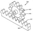
본 발명의 뼈 플레이트 시스템의 몇 가지 유익한 특징은 랙과 피니언 기어와 유사한 도움에 의해 설명될 수 있다. 비록 뼈 플레이트 시스템과 랙과 피니언 기어는 전혀 무관하지만(랙과 피니언 기어는 예를 들어, 자동차 조향 메커니즘과 기관차 및 철도 차량 구동 메커니즘에 이용됨), 본 발명의 뼈 플레이트 시스템은 유사한 개념을 공유한다. 도 4a 내지 도 4c에 도시된 바와 같이, 랙과 피니언 기어 400은 치차 421을 가진 랙 420과 치차 423을 가진 원형 피니언 422를 가진다. 피니언 422에 회전 운동이 가해지면 랙 420이 이동되는 한편, 반대로 랙 420의 선형 운동 또는 이동은 피니언 422을 회전시킨다.Several advantageous features of the bone plate system of the present invention can be explained with the help of a rack and pinion gear. Although the bone plate system and the rack and pinion gears are totally independent (the rack and pinion gears are used, for example, in automotive steering mechanisms and locomotive and rail vehicle driving mechanisms), the bone plate system of the present invention shares a similar concept. As shown in FIGS. 4A-4C, the rack and
유사한 개념은 피니언 422의 곡률 반경 425 주위의 치차 423 배열이다. 도 4b 및 도 4c의 프로파일에 도시된 바와 같이, 기어 치차 423은 균일한 각도로 이격되어 곡률 반경 425를 따른다. 또한, 각각의 치차 423은, 선 427에 의해 지시되는 바와 같이, 치차 423을 양분하는 선이 곡률 반경 425의 중심 426을 교차하여 반경 424를 가진 원을 형성한다. 유사하게, 선 429에 의해 표시되는 바와 같이, 인접한 치차들 423 사이의 그 어떤 공간 428을 양분하는 선 또한 중심 426을 교차한다. 본 발명에 따른 각도 조절 가능한 잠금 스크류의 헤드의 나사산 프로파일(스크류의 중심 축에 수직인 방향에서 바라 볼 때)은 도 4c의 피니언 치차 423과 공간 428의 부분 프로파일 관찰(view)의 그것과 유사하다.A similar concept is the
도 5a 내지 도 5c는 본 발명에 따른 각도 조절 가능한 잠금 스크류의 실시예를 도시한다. 각도 조절 가능한 잠금 스크류 500은 부분-구형 헤드 502와 샤프트 504를 가진다. 헤드 502는 나사산 503을 가지고, 샤프트 504는 나사산 507을 가진다. 헤드 502는 바람직하게 뼈 그리고 뼈 플레이트 구멍 속으로 박아 넣거나 뽑아 내는 도구를 수납하기 위한 리세스 509를 가진다. 바람직하게, 팁 506과 샤프트 나사산 507은 뼈 속으로의 이식을 용이하게 하기 위해 자기-탭핑 및/또는 자기-드릴링이다. 헤드 502와 샤프트 504는 적절한 배치에 도움이 되는 가이드 와이어를 수납하기 위한 캐뉼라 일 수 있다. 도 5b 및 도 5c는 곡률 반경 525를 따르는 나사산 503의 프로파일을 도시한다. 하나의 실시예에 있어서, 반경은 대략 2mm이다. 프로파일에 보이는 나사산 503의 피크들 510과 골들 512의 각각은, 본 실시예에서, 바람직하게 대략 60도 각도인 나사산 각도들 517에서 플랭크들 511에 의해 연결된다. 나사산 프로파일 라인들 518a 내지 518f는 골들 512를 통해 확장되어 곡률 반경 525의 중심 526을 교차하는 일련의 라인들이 생겨난다. 프로파일 라인들 518a 내지 518f는 나사산 503을 절단하기 위해 헤드 502의 외부 구형 표면을 절단 비트(cutting bit)가 접촉할 때 나사산 절단기의 절단 비트 505의 세로 축 501의 연장에 의해 형성된다. 본 실시예에 있어서, 절단 비트 505는 나사산 503이 절단될 때 헤드 502의 외부 구형 표면에 항상 직교한다. 또한, 본 실시예에 있어서, 곡률 반경은 곡률 중심 526이 스크류 500의 중심 축 519에 놓이게 한다. 스크류의 길이 및 치수에 의존하여, 중심 526은 스크류의 중심 축에 놓일 수도 그렇지 않을 수도 있다. 또한, 스크류의 치수들이 일정하게 유지될 때 반경이 증가되면, 반경 중심은 예를 들어, 도 6에 도시된 바와 같이, 스크류헤드 외측으로 움직일 것이다.5a to 5c show an embodiment of the angle adjustable locking screw according to the invention. The angle
도 6은 본 발명의 각도 조절 가능한 잠금 스크류의 다른 실시예를 도시한다. 본 실시예에 있어서, 각도 조절 가능한 스크류 600의 스크류헤드 602는 스크류 500보다 큰 곡률 반경 625를 가진다. 이것은 골 프로파일 라인들 618a 내지 618f가 스크류 600의 중심축 619로부터(수직으로 측정된)의 간격 630인 곡률 반경 중심 626을 교차하게 하는 결과를 초래한다. 만약, 예를 들어, 반경 624가 10mm이면, 2.4mm 스크류(2.4mm는 샤프트 604의 대직경을 나타냄)를 위해, 간격 630은 대략 8.2mm일 수 있다. 그러나, 곡률 반경이 증가할 때, 스크류헤드는 구형 모양이 더 없어져서, 나사산 프로파일은 알려진 잠금 스크류헤드들과 같이, 보다 더 직선(예, 라인 313 내지 316과 같이)과 정렬되는 것을 유의해야 한다. 6 shows another embodiment of the angle adjustable locking screw of the present invention. In this embodiment, the
도 7은 본 발명에 따른 각도 조절 가능한 스크류헤드의 또 다른 실시예를 도시한다. 스크류헤드 702는 중심 축 719, 나사산 703, 및 구동/추출 도구를 수납하기 위한 리세스 709를 가진다. 전술한 실시예들에 있어서,나사산 703의 프로파일은 아크-모양(즉, 비-선형)의 곡률 반경 725를 따르고, 나사산 피크들 710, 골들 712, 및 플랭크들 711을 포함한다. 그러나, 전술한 실시예들과 달리, 나사산 프로파일 라인들은 곡률 반경의 중심을 교차하지 않는다. 대신에, 골 프로파일 라인들 718a 내지 718f에 의해 표시되는, 나사산 프로파일 라인들은 서로 평행하게 확장하여 중심 축 719에 직교한다. 나사산 절단기의 절단 비트 705가 나사산 703을 절단하기 위해 헤드 702의 외부 구형 표면을 접촉하고, 라인들 718a 내지 718f는 절단 비트 705의 세로 축 701의 연장을 나타내는 방식 때문에, 이러한 라인들은 이러한 방식으로 확장한다. 기능적으로, 이러한 차이는 보다 덜한 이상적 스크류헤드/구멍 나사산 결합을 초래한다. 그러나, 스크류헤드 702는 현재 스크류헤드 502보다 제작하기 더 쉽다. 7 shows yet another embodiment of an angle adjustable screwhead according to the invention.
도 8은 잠금 뼈 플레이트 구멍들 832, 비-잠금 뼈 플레이트 구멍들 834, 및 잠금/비-잠금 뼈 플레이트 구멍 836의 조합을 포함하는 종래의 뼈 플레이트 구멍들을 가진 뼈 플레이트 800을 도시한다. 각각의 구멍은 정상 표면 837로부터 바닥의 뼈-결합 표면 839를 통해 완전히 확장한다. 잠금 플레이트 구멍들 832는 잠금 뼈 스크류의 헤드 주변의 나사산들과 결합하기 위해 구멍의 내부 표면 주위에 확장하는 나사산들 833을 가진다. 종래의 잠금 플레이트 구멍들은, 도시된 바와 같이, 정상 표면 837로부터 바닥 표면 839까지 완전히 확장하는 나사산들 833을 가질 수도 있고, 아니면 대안적으로, 뼈 플레이트의 상면과 바닥면 사이의 수직 거리의 부분에만 확장하는 나사산을 가질 수도 있다. 비-잠금 플레이트 구멍들 834는 비-잠금 뼈 스크류의 헤드를 수용하기 위한 비-나사산 또는 매끈한 내부 측면들 835를 가진다. 복합 잠금/비-잠금 플레이트 구멍 836은 외과의사로 하여금 잠금 스크류 또는 비-잠금 스크류를 구멍을 통과시키는데 사용하게 함으로써 뼈 플레이트의 다양성을 증가시킨다. 복합 구멍 836은 잠금 뼈 스크류를 수납하기 위해 구멍의 내부 표면 주위에 나사산 833을 가진 일단과 비-잠금 뼈 스크류를 대안적으로 수납하기 위한 매끄럽거나 비-나사산 내부 표면 835를 가진 타단을 가진다.8 shows a
도 9a 및 도 9b는 본 발명에 따른 뼈 플레이트 구멍들 940을 가진 뼈 플레이트 900을 도시한다. 종래의 잠금 스크류 뼈 플레이트 구멍들에서와 같은 플레이트 구멍들의 내부 표면 935 주위의 나선형 나사산 대신에, 바람직하게 나사 부분들의 수직 기둥들 942는 구멍의 내부 표면 주위에 배열된다. 나사산 부분 기둥들은, 서로 결합하도록 확장될 경우(즉, 내부 표면 935 주위에 완전히 확장할 경우), 나선형 나사산을 형성할 것이다. 기둥들은 상부 표면 937로부터 하부 표면 939쪽 방향으로 확장하여 구멍의 내부 표면 주위에서 동일 간격으로 이격되게 위치된다. 기둥 당 나사산 부분들 921의 수는 외과적 적용들 및 뼈 플레이트 및 뼈 스크류의 치수들(예, 플레이트 두께 및 나사산 피치)에 따라 변화될 수 있다. 그러나, 각각의 기둥은 적어도 두 개의 나사산 부분들을 가져야 하며 바람직하게 스크류와 플레이트 사이의 고정된 각도 관계를 보다 확보해야 한다. 나사산 부분들 대신에, 기둥들 942는 대안적으로 그 위에 형성된 복수의 치차들을 가질 수 있음을 유의해야 한다. 치차의 기둥들은, 서로 결합하도록 확장하게 되면(즉, 내부 표면 935 주위에 완전히 확장하면), 나선형 나사산을 형성하는 것이 아니라, 뼈 플레이트 구멍의 중심 축에 수직인 일련의 동심 돌기들(ridges) 또는 그루브들을 형성할 것이다. 그러한 치차의 기둥들은 또한 비-잠금, 잠금, 및 각도 조절 가능한 잠금 뼈 스크류들을 수납할 수 있는 한편, 치차와 잠금 및 각도 조절 가능한 잠금 뼈 스크류들의 스크류헤드 나사산들의 결합은, 나사산 부분들과 잠금 및 각도 조절 가능한 잠금 뼈 스크류들의 스크류헤드 나사산들의 결합보다 덜 이상적이다.9A and 9B show
도 9a 및 도 9b에 도시된 바와 같이, 본 발명의 뼈 플레이트 구멍들은 바람직하게 나사산 부분들의 4개의 기둥들 942를 가진다. 그러나, 본 발명의 뼈 플레이트 구멍들의 대안적으로 다른 수의 나사산 부분들의 기둥들을 가질 수 있다.As shown in Figures 9A and 9B, the bone plate holes of the present invention preferably have four
예를 들어, 도 10a 내지 도 10c 및 도 10d 내지 도 10f의 두 개의 실시예들에 각각 설명된 바와 같이, 각각의 뼈 플레이트들 1000A 및 1000D의 뼈 플레이트 구멍들 1040A 및 1040D는 각각 나사산 부분들의 6개의 기둥들을 가진다(사시도로 도시되었기 때문에, 도 10c 및 도 10f에서는 3개의 기둥들만 볼 수 있음을 주의할 것). 나사산 부분 기둥들 1042A와 나사산 부분 기둥들 1042D 사이의 차이는 나사산 부분들 1042A의 기둥 폭 1041A는 나사산 부분들 1042D의 기둥 폭 1041D의 그것의 대략 두 배라는 사실이다. 스크류헤드 나사산과 나사산 부분 기둥들의 교차-나사 결합의 증가된 위험 때문에, 나사산 부분들의 6개 기둥들 이상은 추천되지 않는다. 반대로, 나사산 부분들의 3개의 기둥들보다 더 많이 가진 본 발명의 뼈 플레이트 구멍들 또한 뼈/플레이트 계면에서의 불충분한 안정성의 증가된 가능성 때문에 추천되지 않는다.For example, as described in the two embodiments of FIGS. 10A-10C and 10D-10F, respectively, the bone plate holes 1040A and 1040D of the
도 11은 본 발명에 따른 뼈 플레이트 구멍의 단면을 도시한다. 뼈 플레이트 구멍 1140은 상부 표면 1137로부터 하부 뼈-결합 표면 1139쪽으로 뼈 플레이트 1100을 완전히 관통 확장하여 형성된다. 구멍 1040은 정상부 1144, 중간부 1146, 및 바닥부 1148을 구비하는 내부 표면 1135를 가진다. 정상부 1144는 상부 표면 1137로부터 중간부 1146까지 확장한다. 중간부 1146은 정상부 1144로부터 바닥부 1148까지 확장하고 바람직하게 구멍의 최소 직경을 가진다. 그리고, 바닥부 1148은 중간부 1146으로부터 하부 표면 1139까지 확장한다. 정상부 1144는 나사산이 없고, 바람직하게 매끄러운 내부 표면 1143을 가지며, 바람직하게 하부 표면 쪽 내측으로 원뿔형태로 테이퍼진다. 뼈 플레이트 구멍 1140은 정상부 1144와 중간부 1146의 교차점(각각의 기둥의 제1 나사산 부분의 정상)에서 숄더 1145를 가진다. 숄더 1145는 구멍 1140을 통해 삽입된 비-잠금 뼈 스크류의 스크류헤드를 위한 멈춤쇠(stop)로서 기능할 수 있고, 일 실시예에 있어서, 그것이 구멍의 중심 축에 대해 약 60도 각도를 형성하도록 각이 형성된다. 내부 표면 1143 또는 상부 표면 1137은 헤드의 크기 및 모양에 따라 비-잠금 뼈 스크류의 스크류헤드를 위한 멈춤쇠로서 기능할 수 있다. 바닥부 1148은 또한 바람직하게 매끄러운 내부 표면 1149를 가지며, 바람직하게 언더컷 구형 형태로 상부 표면 쪽 내측으로 테이퍼진다. 본 발명의 일 실시예에 있어서, 언더컷 구형의 반경은 1.75mm이다. 대략 2mm의 뼈 플레이트 두께의 경우, 예를 들어, 정상부는 대략 1mm 확장할 수 있고 중간 및 바닥부들은 각각 대략 0.5mm 확장할 수 있다.11 shows a cross section of a bone plate hole according to the invention.
본 실시예에 있어서, 뼈 플레이트 구멍 1140의 중간부 1146은 내부 표면 1135의 나사산 부분들 1142의 4개의 불연속 기둥들을 가진다. 각각의 기둥 1142는 바람직하게 중심 축 1119에 대해 측정된 각도 1150에서 하부 표면 1139 쪽 내측으로 경사진다. 하나의 실시예에 있어서, 각도 1150은 바람직하게 대략 15도이다. 각각의 기둥 1142는 또한 바람직하게 4개 또는 5개의 나사산 부분들 1121을 가진다. 다른 실시예들은 전술한 바와 같이 다소의 나사산 부분들을 가질 수 있다. 2.4mm의 각도 조절 가능한 잠금 스크류를 수용하는 뼈 플레이트 구멍의 경우, 각각의 나사산 부분의 기둥 폭 1141은 바람직하게 대략 0.35mm이다. 다른 실시예들은 적용에 따라 다른 기둥 폭들을 가질 수 있다. In this embodiment, the
도 12는 나사산 부분들 1221의 기둥 1242의 부분의 단면 프로파일을 도시한다(전술한 바와 같이, 치차의 대안적 기둥의 단면 프로파일은 나사산 부분들과 동일하게 보임을 주의). 도 12에 있어서, 기둥 1242의 5개의 나사산 부분들 1221의 2개가 도시된다. 나사산 부분들의 기둥 1242는 바람직하게 각도 1250에서 뼈 플레이트의 하부 표면 쪽으로 경사진다. 일 실시예에 있어서, 각도 1250은 대략 15도이다. 프로파일에 도시된 바와 같이, 나사산 부분들 1221의 기둥 1242는 나사산 각도들 1217에서 플랭크 1211에 의해 서로 연결된 피크들 1210 및 골들 1212를 포함한다. 피크들 1210은 바람직하게 일 실시예에 있어서 대략 0.04mm인 길이 1252를 가진다. 골들 1212는 바람직하게 일 실시예에 있어서, 대략 0.03mm인 반경 1254를 가진다. 각도 1217은 바람직하게 대략 60도이고, 골 프로파일 라인 1218에 표시되는 바와 같이, 골들 1212의 양분은 프랭크 1211로부터 측정된 바와 같이 바람직하게 대략 30도 각도 1256에서 발생된다. 뼈 플레이트 구멍 나사산-부분 기둥들의 다른 실시예들은 다른 값들의 기둥 경사 각도, 피크 길이, 골 반경, 나사산 각도, 및 양분 각도(나사산 각도의 함수)를 가질 수 있다. 12 shows a cross-sectional profile of the portion of the
바람직하게, 본 발명의 각도 조절 가능한 잠금 뼈 스크류들은 선택가능한 각도 범위 내의 선택가능한 각도에서 뼈에 박혀 뼈 플레이트에 고정될 수 있다. 도 13은 뼈 플레이트가 본 발명에 따라 구성된 뼈 플레이트 구멍들 1340을 가진 본 발명의 실시예를 도시한다. 각각의 구멍 1340은 바람직하게 각도 조절 가능한 잠금 스크류 1360을 수납할 수 있고, 또한 각도 범위 내에서 어떤 방향으로도 선택 가능한 각도에서 본 발명에 따라 구성될 수 있다. 각도 범위는, 본 실싱에서 대략 30도 각도인 각도 1362를 가진 원뿔을 형성한다. 다시 말해, 각도 조절 가능한 잠금 스크류 1360은 구멍 1340 속으로 삽입되어 뼈 플레이트 1340의 중심 축 1319에 대해 그 어떤 방향으로 0도 내지 15도 각도의 선택 가능한 범위에서 뼈 플레이트 1300에 고정될 수 있다. Preferably, the angle adjustable locking bone screws of the present invention can be secured to the bone plate embedded in the bone at a selectable angle within the selectable angle range. Figure 13 illustrates an embodiment of the present invention in which the bone plate has bone plate holes 1340 configured according to the present invention. Each
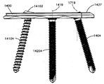
도 14a 내지 도 17b는 본 발명에 따라 구성된 뼈 플레이트 구멍의 유용한 특징을 도시한다. 뼈 플레이트 1400은 적어도 3개의 뼈 플레이트 구멍들 1440을 가진다. 각각의 구멍 1440은 나사산 부분들 1542의 4개의 기둥들을 가지며 바람직하게 비-잠금, 잠금, 또는 각도 조절 가능한 잠금 뼈 스크류 그 어떤 하나를 수납할 수 있다. 14A-17B illustrate useful features of bone plate holes constructed in accordance with the present invention.
도 14a, 도 14b, 도 15a, 및 도 15b에 도시된 바와 같이, 종래의 비-잠금 뼈 스크류 14100은 뼈 플레이트 구멍들 1440의 어느 하나를 통해 삽입될 수 있다. 비-잠금 뼈 스크류 14100은 비-나사산 스크류헤드 14102와 나사산 생크(shank) 14104를 가지며, 각각 구멍 1440과 함께 사용되도록 적절히 크기로 구성된다. 비-잠금 뼈 스크류 14100은 구멍의 중심 축과 동축적으로 구멍 1440을 통해 삽입될 필요는 없지만, 대신에 도 14b에 도시된 바와 같이, 선택가능한 각도에서 구멍 1440을 통해 삽입될 수도 있음을 주의해야 한다. 도 15b는 스크류헤드 14102가 나사산 부분들 1542의 기둥들과 결합하지 않지만, 대신에 그 안에 안착될 때 구멍 1440의 숄더 1545와 접촉하는 것을 도시한다. As shown in FIGS. 14A, 14B, 15A, and 15B, a conventional
도 14a, 도 14b, 도 16a, 및 도 16b는 제2 뼈 플레이트 구멍 1440을 통해 삽입된 종래의 잠금 뼈 스크류 14200을 도시한다. 잠금 뼈 스크류 14200은 외부 표면에 나사산 14203을 가진 스크류헤드 14202를 가진다. 스크류헤드와 나사산 모두는 적절한 크기로 구성됨으로써 나사산 14203은 나사산 부분들 1542의 기둥들과 나사 결합되어 꼭 맞춰질 수 있다. 나사산 부분들 1542의 기둥들과 적절히 결합 및 맞추기 위해, 잠금 뼈 스크류 14200은 구멍 1440을 통해 구멍의 중심 축 1419와 동축적으로 삽입되어야 한다. 스크류 14200는 또한 뼈와 결합을 위해 나사산 생크 14204를 가진다. 생크 14204는 또한 구멍 1440을 통한 삽입을 위해 적절한 크기로 치수화된다. 14A, 14B, 16A, and 16B show a conventional
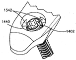
도 14a, 도 14b, 도 17a, 및 도 17b는 제3 뼈 플레이트 구멍 1440을 통해 삽입된 각도 조절 가능한 잠금 뼈 스크류 1460을 도시한다. 본 발명에 따라 구성된, 각도 조절 가능한 잠금 뼈 스크류 1460은 나사산이 형성된 생크 1404 및 그 외부 표면에 나사산 1403을 가진 부분-구형 헤드 1402를 가진다. 스크류헤드 나사산 1403은 헤드 1402의 구형-모양 부분의 아크-모양(즉, 비-선형)의 곡률 반경을 바람직하게 따르는 프로파일을 가진다. 스크류 1460은 나사산 1403이 나사산 부분들 1542의 기둥들과 고정되게 결합된 상태에서 중심 축 1719에 대해 비-동축적으로 제3 구멍 1440 속으로 삽입되게 도시된다.14A, 14B, 17A, and 17B show angle adjustable
도 18a 내지 도 24c는 본 발명에 따른 뼈 플레이트 구멍의 실시예의 다양한 특징들을 설명한다. 구멍의 내부 표면 주위의 기둥들의 형성 이외에, 적어도 몇 가지 이러한 특징들은 본 발명에 따른 뼈 플레이트 구멍의 대안적인 실시예들에 사용될 필요는 없다. 또한, 이러한 특징들이 설명되고 도시된 순서는 본 발명의 뼈 플레이트 구멍을 제조하는 특정의 공정의 순서 또는 단계를 의미하는 것은 아님을 주의해야 한다. 당업자에게 명백한 바와 같이, 본 발명의 구멍들이 구성될 수 있는 한 가지 이상의 방법이 있다.18A-C illustrate various features of embodiments of bone plate holes in accordance with the present invention. In addition to the formation of pillars around the inner surface of the hole, at least some of these features need not be used in alternative embodiments of the bone plate hole according to the invention. In addition, it should be noted that the order in which these features are described and illustrated does not imply any order or step in the particular process of making bone plate holes of the present invention. As will be apparent to those skilled in the art, there is more than one way in which the holes of the present invention can be constructed.
본 발명의 뼈 플레이트 구멍은 전형적으로 도 18a 내지 도 18c에 도시된 바와 같이, 원형 출발 구멍 1865로 시작 된다. 출발 구멍 1865는 중심 축 1819을 가지며 상부 표면 1873으로부터 하부 표면 1839까지 뼈 플레이트 1800을 완전히 확장한다. 일 실시예에 있어서, 출발 구멍의 직경은 대략 2.2mm이다.Bone plate holes of the present invention typically begin with a
도 19a 내지 도 19c는 다른 특징들을 가지지 않은 뼈 플레이트 구멍의 내부 표면 프로파일을 도시한다. 뼈 플레이트 1900의 구멍 1965의 프로파일은 내측으로 테이퍼지는 정상부 1944, 내측으로 돌출되어 테이퍼지는 중간부 1946, 및 구형으로 언더컷된 바닥부 1948을 포함한다. 일 실시예에 있어서, 구멍의 중간 및 바닥부들은 각각 중심 축 1919을 따라 약 1mm 만큼 확장되고, 구형 언더컷의 반경은 대략 1.75mm이다.19A-19C show the inner surface profile of a bone plate hole without other features. The profile of the
도 20a 내지 도 20c에 도시된 바와 같이, 다른 특징은 선택적인 "X 키(key)" 컷아웃(cutout) 2065이다. X 키 컷아웃 2065는 바람직하게, 출발 구멍 1865와 같이 동일한 중심 축 1819에 대해 뼈 플레이트를 완전히 관통하여 프레스, 절단, 또는 스탬프 가공된다. 하나의 실시예에 있어서, "X"의 각각의 레그는 대략 1.5mm의 폭을 가지며 대략 0.75mm의 반경을 가진 아크-모양으로 종결된다. 이와 같은 동일한실시예에 있어서, 동일 직선상의 레그들의 끝단들 사이의 간격은 대략 4.25mm이다. X 키 컷아웃은, 도 25a 내지 도 27d과 관련하여 후술되는 바와 같이, 보충적인 드릴-가이드 팁 디자인을 가진 드릴 가이드를 수용할 의도를 가진 네 잎 클러버 모양을 형성한다. As shown in FIGS. 20A-20C, another feature is an optional “X key”
도 21a 내지 도 21c에 도시된 바와 같이(그 어떤 다른 구멍 특징들이 없는), 다른 특징은 바람직하게 12-도 릴리프 컷(relief cut) 2165이다. 릴리프 컷 2165는 8개의 대칭적인 절단 영역들 2166, 각각의 영역이 뼈 플레이트의 상부 표면 2137로부터 12도로 내측으로 경사진, 4분면 당 두 개의 영역들을 포함한다. 릴리프 컷은 뼈 플레이트를 완전히 관통하여 만들어 진다. 일 실시예에 있어서, 각각의 릴리프 컷 축 2119는 뼈 플레이트 구멍의 중심 축 1819로부터 대략 1.1mm이다. As shown in FIGS. 21A-21C (without any other hole features), another feature is preferably a 12-
도 22a 내지 도 22c는 정상부 1944, 중간부 1946, 바닥부 1948, X 키 컷아웃 2065, 릴리프 컷 2165, 및 그 안에 형성된 4개의 기둥들 2242을 가지며 그들에 아직 치차 또는 나사산 부분들을 가지지 않은 구멍 프로파일을 도시한다. 기둥들 2242는 구멍의 중간부의 내부 표면으로부터 중심 영역들을 제거함으로써 형성된다. 22A-22C show a hole profile having a top 1944, a middle 1946, a bottom 1948, an
나사산 절단 공정은 기둥들 2242에 나사산 부분들을 형성한다. 중간부 1946이 그 안에 형성된 기둥들을 가지지 않게 되면, 나사산 절단 공정은 도 23a 내지 도 23c에 도시된 바와 같이, 구멍 2365의 중간부 2346의 내부 표면 안 그리고 그 주위를 완전히 나선형 나사산 2367 절단을 하게 됨을 주의해야 한다. 나사산 부분들의 나사산 프로파일(즉, 피크들, 골들, 플랭크들, 및 인접한 플랭크들에 의해 형성된 각도들)은 바람직하게 도 11 및 도 12에 도시된 나사산 부분들의 기둥들을 위해 전술한 프로파일과 동일하다.The thread cutting process forms threaded portions in the
전술한 바와 같이, 기둥들 2242에 나사산 부분들을 형성하는 대신에, 치차가 대안적으로 그 안에 형성될 수도 있다. 치차는 구멍의 중심 축에 수직되거나 적어도 실질적으로 수직인 기둥에 그루브들을 절단함에 의해 형성된다. 중간부 1956이 그 안에 형성된 기둥들을 가지지 않으면, 그루브 절단 공정은 동심의, 평행한 일련의 교호하는 그루브들고 돌기들을 형성할 것임으로 주의해야 한다. As mentioned above, instead of forming threaded portions in the
도 24a 내지 도 24d는 본 발명에 따른 뼈 플레이트 구멍의 완성된 실시예를 도시한다. 구멍 2440은 나사산 부분들 2442의 기둥들, X 키 컷아웃 2065, 및 릴리프 컷 2165를 포함한다. 도 24c는 구멍 2440의 정상면 2437을 도시하는 한편, 도 24d는 뼈와의 접촉을 의도하고, 뼈에 인접되거나 뼈에 면하는 구멍 2440의 바닥면 2439를 도시한다.24A-24D show a completed embodiment of a bone plate hole according to the present invention.
도 25a 내지 도 27d는 드릴 가이드들과 관련한 본 발명의 바람직한 다른 특징을 도시한다. 본 발명에 따라 구성된 드릴 가이드의 일 실시예는 도 25a 내지 도 26c에 도시된고, 다른 실시예는 도 27a 내지 도 27d에 도시된다.25A-27D show another preferred feature of the present invention in connection with drill guides. One embodiment of a drill guide constructed in accordance with the present invention is shown in FIGS. 25A-26C and another embodiment is shown in FIGS. 27A-27D.
도 25a는 팁 2572 및 핸들 2573을 가진 드릴 가이드 2570을 도시한다. 도 25b에 도시된 바와 같이, 팁 2571은 드릴, 뼈 스크류를 안내하고, 및/또는 뼈 플레이트 2500을 통해 선택된 각도에서 뼈 속으로 도구를 박아 넣고/추출하기 위한 드릴 샤프트 주위에 배열되된 네 잎 클로버 모양 디자인을 형성하는 4개의 동일 간격으로 이격되고 라운드진 윙 또는 영역들 2572를 가진다. 윙들 2572는 뼈 플레이트 구멍들 2540의 X 키 컷아웃 1965 내부에서 꼭 맞도록 고정되게 구성된다. 이것은 구멍이 뼈에 천공되고/또는 뼈 스크류가 뼈에 박혀지는 동안, 드릴 가이드 2570이 뼈 플레이트 구멍 2540에 동축적으로(즉, 뼈 플레이트 구멍의 중심 축과 동축적으로) 삽입되어 정 위치에서 쉽게 유지되는 것을 허용한다. 대안적으로, 네잎 클로버 모양의 디자인과 X 키 컷아웃과 다른 구성들은 각각 팁 2571 및 구멍들 2540을 위해 각각 사용될 수 있음을 주의해야 한다. 도 25c에 도시된 바와 같이, 핸들 2573은 팁 2571 및 팁 2571이 삽입되는 구멍 2540의 중심 축에 대해 360도 회전될 수 있다.25A shows
도 26a는 그곳을 통해 선택 가능한 범위 내에서 드릴링이 가능한 슬롯 2675를 가진 드릴 가이드 2570을 도시한다. 본 실시예에 있어서, 선택 가능한 각도의 범위는 0도부터 15도이다. 따라서, 360도 선회할 수 있는 핸들 2573의 능력은 구멍의 중심 축 주위에서 30도의 원뿔 각도를 제공한다. 드릴 가이드 2570은, 본 실시예에서, 구멍의 중심 축에 대해 각각 0, 5, 10, 및 15도 각도를 나타내는 슬롯 2675를 따라 마킹들 2674a 내지 2674d를 가진다. 다른 실시예들은 다른 각도 범위들 및/또는 선택 가능한 각도의 다른 마팅들을 가질 수도 있다. 도 26a 및 도 26b는 드릴 가이드 2570을 통하고, 뼈 플레이트 2500를 통하고, 본 실시예에서 뼈 플레이트 구멍의 중심 축에 대해 0도(즉, 동축임)인 최상부 각도 설정 2674a에서 뼈 2678 속으로 안내된 드릴 비트 2676을 도시한다. 도 26c는 드릴 가이드 2570을 통하고, 뼈 플레이트 2500를 통하고, 본 실시예에서 뼈 플레이트 구멍의 중심 축에 대해 15도이거나 뼈 플레이트 2500의 정상면 2637에 대해 75도인, 최하부 각도 설정 2674d에서 뼈 2678 속으로 안내된 드릴 비트 2676을 도시한다. FIG. 26A shows a
도 27a 내지 도 27d는 본 발명에 따른 드릴 가이드의 다른 실시예를 도시한다. 드릴 가이드 2770은 일단에서 팁 2771A를 가진 깔때기-모양 가이드 2777, 대향단에서 팁 2771B를 가진 동축 가이드 2779, 및 그 사이의 핸들 2773을 포함한다. 팁 2771A와 팁 2771B 각각은 드릴, 뼈 스크류를 안내하고, 및/또는 뼈 플레이트를 통해 뼈 속으로 도구 2776을 박거나/추출하기위한 드릴 샤프트 주위에서 네 잎 클로버 디자인을 형성하는 4개의 등간격으로 이격되고 라운드진 윙들 또는 영역들 2772를 가진다. 윙들 2772는 본 발명의 뼈 플레이트 구멍들(예, 뼈 플레이트 구멍들 2540)의 X 키 언더컷 1965 내부에 꼭 맞게 결합하도록 구성된다. 이것은, 구멍이 뼈에 천공되고 및/또는 뼈 스크류가 뼈에 박히는 동안, 드릴 가이드 2770의 어느 일단이 뼈 플레이트 구멍 속에 동축적으로(즉, 뼈 플레이트 구멍의 중심축에 동축적으로) 삽입되어 정위치에 용이하게 유지되게 한다. 대안적으로, 네 잎 클로버 디자인 및 X 키 컷아웃 이외의 구성들은 본 발명의 팁 2771A 및 2771B 및 구멍들을 위해 각각 사용될 수 있음을 주의해야 한다. 드릴 가이드 2570의 핸들 2573과 달리, 핸들 2773은 팁 2771A 또는 팁 2771B의 어느 하나에 대해 선회하지 않는다. 대신에, 깔때기-모양 가이드 2777은 그곳을 관통하여 확장하고 팁 2771A가 삽입되는 뼈 플레이트 구멍의 중심 축을 기준으로 중심을 맞춘 깔때기-모양 보어 2775를 가진다. 보어 2775는 본 실싱예에서 30도인, 원뿔 각도를 제공한다. 깔때기-모양 가이드 2777이 본 발명의 뼈 플레이트 구멍에 삽입됨으로써, 고정된 위치에서 잠겨진 태에서, 구멍의 중심 축에 대해 0도부터 15도 각도의 범위에서 그 어떤 방향으로 선택 가능한 각도에서 바람직하게 드릴링 만들어질 수 있다. 드릴 가이드 2770의 대향단에서, 동축 가이드 2779는 그곳을 관통하여 확장하는 보어 2778을 가진다. 동축 가이드 2779가 본 발명의 뼈 플레이트 구멍에 삽입된 상태에서, 보어 2778은 드릴 비트를 안내하거나 구멍의 중심 축에 동축적으로 도구 2776을 박어넣고/추출하는데 사용될 수 있다. 동축 가이드 2779는 또한 침투 깊이를 결정하는 것을 돕는 선택적인 측정 게이지 2774를 가진다.27A-27D show another embodiment of a drill guide according to the invention.
도 28은 본 발명에 따른 뼈 플레이트 구성을 도시한다. 뼈 플레이트 2800은 측면 근위 경골 플래토우(lateral proximal tibial plateau)에 적합하지만 이에 한정되지는 않는 모양 및 구성이다. 뼈 플레이트 2800은 측면 근위 경골의 뼈몸통끝에 따르도록 구성된 헤드부 2880, 및 측면 근위 경골의 뼈몸통에 따르도록 구성된 샤프부 2882를 가진다. 뼈 플레이트 2800은 또한 상부 표면 2837, 및 상부 표면 2837로부터 바닥 표면까지 뼈 플레이트를 완전히 관통하여 확장하는 다수의 뼈 플레이트 구멍들 2840을 가진다. 각각의 구멍 2840은 4개의 나사산 부분들 2842 기둥들을 가지며 바람직하게 본 발명에 따른 비-잠금, 잠금, 각도 조절 가능한 잠금 뼈 스크류의 어느 하나를 수납할 수 있다. 샤프트부 2882는 또한 여러개의 숫자 8-모양의 복합 구멍들 2884를 가져서 그 활용성이 증대되며, 숫자 8-모양의 하나의 부분 2885는 바람직하게 4개의 나사산 부분들의 기둥들을 가지고 다른 부분 2886은 바람직하게 매끄럽고 사사산이 없다. 부분 2886은 비-잠금 뼈 스크류를 수납할 수 있는 한편, 부분 2885는 바람직하게 비-잠금, 잠금, 또는 각도 조절 가능한 잠금 뼈 스크류의 어느 하나를 수납할 수 있다. 각도 조절 가능한 잠금 뼈 스크류를 샤프트부 2882에 사용할 수 있는 능력은 특히 극 피질(far cortex)의 상태 때문에 비-잠금 스크류들을 이용한 고정이 어려워서 뼈몸통의 극 피질 부분이 소실되거나 심하게 손상된 경우 유용하다. 뼈 플레이트 구멍들의 특정 형태 및 배치는 물론 변화될 수 있다. Figure 28 illustrates a bone plate configuration according to the present invention.
도 29a 내지 도 29c는 본 발명에 따른 다른 뼈 플레이튼 구성(이것은 도 25 내지 도 27에 도시된 뼈 플레이트와 동일함)을 도시한다. 뼈 플레이트 2900은 원위 요골(distal radius) 골절에 맞지만 이에 한정되지 않는 모양 및 구성이다. 뼈 플레이트 2900은 원위 요골의 뼈몸통끝에 따르도록 구성된 헤드부 2980, 및 원위 요골의 뼈몸통에 따르도록 구성된 샤프트부 2982를 가진다. 뼈 플레이트 2900는 또한 상부 표면 2937, 하부 표면 2939, 및 상부 표면 2937로부터 하부 표면 2939까지 뼈 플레이트를 완전히 관통하여 확장하는 다수의 뼈 플레이트 구멍들 2940을 가진다. 각각의 구멍 2940은 바람직하게 4개의 나사산 부분들 2942 기둥들을 가지며 본 발명에 따른 비-잠금, 잠금, 각도 조절 가능한 잠금 뼈 스크류의 어느 하나를 수납할 수 있다. 샤프트부 2982는 또한 증대된 다양성을 위해 여러 개의 복합 구멍들 2984 및 2989를 가진다. 복합 구멍들의 구멍 부분들 2985는 바람직하게 4개의 나사산 부분들 2942의 기둥들을 가지고, 다른 부분들 2886 및 2887은 바람직하게 매끄럽고 나사산이 없다. 부분들 2886 및 2887은 비-잠금 뼈 스크류를 수납할 수 있는 한편, 부분들 2885는 바람직하게 비-잠금, 잠금, 각도 조절 가능한 잠금 뼈 스크류의 어느 하나를 수납할 수 있다. 일 실시예에 있어서, 뼈 플레이트 2900의 길이 2990은 대략 65mm이고, 헤드부 2980의 폭 2992은 대략 22.2mm이고, 헤드부 2980가 샤프트부 2982에 대해 상방으로 경사진 각도 2994는 대략 25도이다.29A-29C show another bone platen configuration according to the present invention, which is the same as the bone plate shown in FIGS. 25-27.
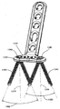
도 30에 도시된 바와 같이, 본 발명의 뼈 플레이트들은 바람직하게 뼈 플레이트의 하부 표면 또는 하측과 뼈 사이에서의 접촉을 제한 및/또는 최소화하는 형상일 수 있다. 뼈 플레이트와 뼈 사이의 접촉의 제한 및/또는 최소화는 혈액 공급에 대한 감소된 피해 및 보다 용이한 플레이트 제거를 포함하는 다수의 생물학적 및 기계적 장점들을 가진다. 뼈 플레이트 3000과 뼈 사이의 접촉을 제한 및/또는 최소화하는 하나의 방법은 뼈 플레이트 구멍들 사이의 하부 표면 3039에 둥걸거나 조개모양의 컷아웃 3099을 가진 플레이트 3000를 제공하는 것이다. 다른 방법들은 미국 특허 번호 제5,151,103호; 제5,053,036호; 제5,002,544호; 및 제4,838,252호에 개시되어 있다. 이러한 특허들의 내용들은 인용에 의해 본 명세서에 합체된다.As shown in FIG. 30, the bone plates of the present invention may preferably be shaped to limit and / or minimize contact between the lower surface of the bone plate or between the underside and the bone. Limiting and / or minimizing contact between bone plate and bone has a number of biological and mechanical advantages, including reduced damage to the blood supply and easier plate removal. One method of limiting and / or minimizing contact between
도 31은 뼈 골절에 적용될 때 본 발명의 뼈 플레이트 시스템의 실시예를 도시한다. 뼈 플레이트 2900은 헤드부 2980의 뼈 플레이트 구멍들 2940을 통해 다양한 선택 가능한 각도에서 삽입되고, 구멍들 2940의 나사산 부분들의 기둥들을 통해 뼈 플레이트 2900에 부착된 4개의 각도 조절 가능한 잠금 스크류들 3160을 통해 골절된 뼈 3178에 부착되도록 도시된다. 뼈 플레이트 구멍들 2940의 내부 표면의 나사산 부분들의 기둥들은 랙-앤-피니언과 대체로 유사한 각도 조절 가능한 잠금 스크류들 3160의 구형-모양 헤드의 나사산과 상호 작용 및 맞춰져서, 각도 조절 가능한 스크류들 3160이 다양한 각도에서 플레이트 구멍들 2940에 고정되는 것을 허용한다. 각도 조절 가능한 잠금 스크류들 3160은 본 발명에 따라 구성되고, 예를 들어, 각도 조절 가능한 잠금 스크류들 500, 600, 및/또는 700일 수 있다. 뼈 플레이트 2900은 또한 뼈 플레이트 구멍 2989의 부분 2987을 통해 삽입된 비-잠금 뼈 스크류 31100을 통해 뼈 3178에 부착된다. 뼈 플레이트 2900은 또한 뼈 플레이트 구멍들 2984의 각각의 부분들 2985를 통해 삽입되어 부분들 2985의 나사산 부분들의 기둥들을 통해 뼈 플레이트에 고정된 한 쌍의 종래의 잠금 뼈 스크류들 31200을 통해 뼈 3178에 부착된다. 뼈 플레이트 구멍들의 나사산 부분들의 기둥들은 잠금 스크류들의 나사산 헤드들과 결합되어 잠금 스크류들을 뼈 플레이트에 고정시킨다. 본 발명의 각도 조절 가능한 잠금 뼈 스크류들은 잠금 스크류들 31200 대신에 사용될 수도 있었음을 주의해야 한다. 또한, 모든 뼈 플레이트 구멍들이 각각의 적용에 사용될 필요는 없다는 것을 주의해야 한다. 각도 조절 가능한 잠금 스크류들 3160, 비-잠금 스크류 31100, 및 잠금 스크류들 31200은, 플레이트 2900가 이식되어 남아 있는 동안, 뼈 플레이트 2900를 통해 뼈 3178 속으로 삽입되어 남아 있다. 31 illustrates an embodiment of a bone plate system of the present invention when applied to bone fractures.
본 발명에 따라 구성된 각도 조절 가능한 뼈 스크류들의 스크류헤드 나사산 특징들로 돌아 가면, 도 32 내지 도 34는 각각의 스크류의 중심 축을 따라 측정된 변화되는 나사산 피치들(예, 피크와 피크 사이의 간격)을 설명명하는 각도 조절 가능한 잠금 스크류 스크류헤드의 3개의 실시예를 도시한다. 아래의 [표 1]은 설명된 스크류헤드가 속하는 속도 조절 가능한 스크류의 크기 및 가변하는 피치들(모든 치수는 밀리미터이다)을 열거한다.Returning to the screwhead threading features of angular adjustable bone screws constructed in accordance with the present invention, FIGS. 32-34 show varying thread pitches measured along the central axis of each screw (eg, peak to peak spacing). Three embodiments of angle adjustable locking screw screwheads are shown. Table 1 below lists the size and variable pitches (all dimensions are in millimeters) of the speed adjustable screw to which the described screwhead belongs.
피치
pitch
본 발명의 각도 조절 가능한 뼈 스크류들의 다른 실시예들은 다른 가변 나사산 피치들을 가질 수 있다.Other embodiments of the angle adjustable bone screws of the present invention may have other variable thread pitches.
각각의 경우에 있어서, 곡률 반경을 따라 측정될 때 인접한 나사산 피크들(또는 인접한 나사산 골들) 사이의 각도 간격은 도 35에 도시된 바와 같이 일정하다. 즉, 곡률 반경 3525을 따라 측정될 때 인접한 나사산 피크들 3510 사이의 각각의 각도 간격 35AD는 동일하고--대조적으로, 도 32 내지 도 34에서 설명된 바와 같이, 나사산 피치들 35P01 내지 35P05는 중심 축 3519을 따라 또는 평행하게 측정될 때 변화한다.In each case, the angular spacing between adjacent thread peaks (or adjacent thread valleys) as measured along the radius of curvature is constant as shown in FIG. 35. That is, each angular spacing 35AD between
동일한 형태의 뼈 플레이트 구멍을 사용하는 동일한 뼈 플레이트의 각도 조절 가능한 잠금 스크류들, 잠금 스크류들, 및 비-잠금 스크류들을 조합에 의해, 본 발명은 신규한 혼합된 고정을 제공한다. 비-잠금 스크류들을 이용하여, 골절 정복은 뼈 플레이트와 뼈 사이에 마찰에 의해 고정된다. 이러한 마찰은 뼈에 있는 비-잠금 스크류를 조임으로서 생성된다. 그러나, 비-잠금 스크류들과 뼈 사이의 미세한 운동은 뼈 흡수를 초래하고 결과적으로 정복 손실을 초래한다. 부가적으로, 비-잠금 스크류들의 삽입은 뼈로 하여금 비-잠금 스크류들 주위를 둘러 싸는 뼈에 높은 응력을 생성하는 스크류 조임 응력을 견딜 필요가 있게 한다. 보통은, 높은 응력은 비-잠금 스크류 나사산들이 뼈에서 미끄러지고(즉, 뼈의 나사산의 전단 응력 파괴) 및/또는 뼈에서 점점 나아가도록 한다(왜냐하면, 뼈는 점탄성 물질이므로). 이들 현상들의 어느 하나는 또한 정복의 손실의 결과를 초래한다.By combining angle adjustable locking screws, locking screws, and non-locking screws of the same bone plate using the same type of bone plate hole, the present invention provides a novel mixed fixation. Using non-locking screws, fracture reduction is fixed by friction between the bone plate and the bone. This friction is created by tightening the non-locking screw in the bone. However, fine movement between the non-locking screws and the bone results in bone absorption and consequent loss of reduction. In addition, the insertion of the non-locking screws enables the bone to withstand the screw tightening stresses that create a high stress on the bone surrounding the non-locking screws. Normally, high stresses cause non-locking screw threads to slip in the bone (ie, breakage of shear stress in the threads of the bone) and / or to progress out of the bone (because the bone is a viscoelastic material). Either of these phenomena also results in loss of conquest.
적어도 하나의 잠금 또는 각도 조절 가능한 잠금 스크류를 부가함에 의해, 정복의 손실은 최소화되거나 제거된다. 특히, 잠금 스크류들을 뼈가 아닌 뼈 플레이트에 고정함으로써, 뼈의 점탄성 거동의 효과가 감소되고, 나사산들은 미끄러지지 않으며, 미세운동도 방지된다. 잠금 스크류들과 뼈 플레이트 사이의 부착은, 잠금 스크류가 뼈를 통해 측방으로 절단되어야 파괴되는 고정된 각도 구성의 고강도 연결이다.By adding at least one locking or angle adjustable locking screw, loss of reduction is minimized or eliminated. In particular, by fixing the locking screws to the bone plate rather than the bone, the effect of the viscoelastic behavior of the bone is reduced, the threads do not slip and the micromovement is also prevented. The attachment between the locking screws and the bone plate is a high-strength connection in a fixed angle configuration in which the locking screw must be cut laterally through the bone.
각도 조절 가능한 스크류들은 잠금 스크류들보다 더 바람직한 각도에서 고정될 수 있으므로, 각도 조절 가능한 스크류들의 사용은 잠금 스크류들보다 더 큰 장점을 제공한다. Since the angle adjustable screws can be fixed at a more desirable angle than the locking screws, the use of angle adjustable screws offers a greater advantage than the locking screws.
또한, 특정의 관절 주변 골절의 처리는 전형적으로 뼈 플레이트에 대해 다양한 각도에서 스크류들의 삽입이 따르고, 개별 스크류들과 뼈 플레이트 사이의 초기 각도 관계를 유지시키는 중요성의 관점에서, 본 발명의 매우 다재 다능한 뼈 플레이트 시스템은 특히 이러한 치료 적용들에 잘 적응된다.Furthermore, the treatment of certain periarticular fractures typically involves the insertion of screws at various angles to the bone plate, and in view of the importance of maintaining the initial angular relationship between the individual screws and the bone plate, the very versatile of the present invention. One bone plate system is particularly well adapted to such therapeutic applications.
본 명세서에서 설명되고 예시된 특징들은 뼈 플레이트 시스템들의 다른 특징들 및 실시예들과 단독으로 또는 조합으로 사용될 수 있음을 유의해야 한다.It should be noted that the features described and illustrated herein can be used alone or in combination with other features and embodiments of bone plate systems.
따라서, 본 발명은 바람직한 실시예들과 관련하여 설명되었다. 그러나, 본 발명은 본 발명의 예들에 불과한 그러한 실시예들에 한정되어서는 아니된다. 당업자들은 다양한 변형들이 본 발명의 범위를 벗어나지 않은 한도내에서 가능하고, 본 발명은 이어지는 청구범위에 의해서만 한정되는 것을 평가할 것이다.Thus, the present invention has been described with reference to preferred embodiments. However, the present invention should not be limited to such embodiments, which are merely examples of the present invention. Those skilled in the art will appreciate that various modifications are possible within the scope of the invention and that the invention is limited only by the claims that follow.
100...비-잠금 뼈 스크류 102...비-나사산 헤드
104...샤프트 107...샤프트 나사산
106...팁 400...랙과 피니언 기어
420...치차 422...피니언
500...잠금 스크류 502...부분-구형 헤드
504...샤프트 503...나사산
510...피크 512...골
511...플랭크 600...각도 조절 가능한 스크류
602...스크류헤드 625...곡률 반경
702...스크류헤드 709...리세스
832...잠금 뼈 플레이트 구멍 834...비-잠금 뼈 플레이트 구멍
900...뼈 플레이트 940...뼈 플레이트 구멍100 ...
104 ...
106 ...
420 ... gear 422 ... pinion
500 ... lock
504
510 ... peak 512 ... goal
511 ...
602
702.Screwhead 709.Recess
832 ... lock
900 ...
Claims (25)
상기 뼈와 결합하도록 구성된 샤프트;
곡률 반경을 가진 구형-모양 부분을 가지며, 상기 구형-모양 부분의 외부 표면에 사사산을 가진 헤드를 구비하며;
상기 나사산은 피크들(peaks), 골들(troughs), 및 플랭크들(flanks)을 구비하는 프로파일(profile)을 가지며, 상기 플랭크들은 피크들과 골들을 연결하고, 상기 피크들과 상기 골들은 상기 곡률 반경과 평행하거나 동심원인 비-선형 곡선들에 놓여지는 것을 특징으로 하는 뼈 플레이트 시스템.In a bone plate system for securing a bone plate to a bone, the bone plate system having a bone screw with a central axis:
A shaft configured to engage the bone;
A head having a spherical-shaped portion with a radius of curvature and having a tetrapod on an outer surface of the spherical-shaped portion;
The thread has a profile having peaks, troughs, and flanks, the flanks connecting the peaks and the valleys, the peaks and the valleys being the curvature. Bone plate system, characterized in that it lies in non-linear curves parallel or concentric with the radius.
상기 나사산 프로파일은 상기 곡률 반경의 중심을 교차하는 프로파일 라인들을 가지며, 상기 프로파일 라인들은 절단 비트(cutting bit)가 상기 헤드의 상기 구형-모양 부분의 상기 외부 표면과 접촉할 때 나사선 절단기(thread cutter)의 상기 절단 비트의 세로 축의 확장을 나타내는 것을 특징으로 하는 뼈 플레이트 시스템.The method of claim 1,
The thread profile has profile lines that cross the center of the radius of curvature, the profile lines when a cutting bit contacts the outer surface of the spherical-shaped portion of the head. Bone plate system, characterized in that the expansion of the longitudinal axis of the cutting bit.
상기 나사산 프로파일은 상기 중심 축에 수직되게 측정된 중심 축으로부터 단지 10mm 이격되어 위치된 지점을 교차하는 프로파일 라인들을 가지며, 상기 프로파일 라인들은 나사산 절단기의 절단 비트가 상기 헤드의 상기 구형-모양 부분의 상기 외부 표면과 접촉할 때 상기 절단 비트의 세로 축의 확장을 나타내는 것을 특징으로 하는 뼈 플레이트 시스템.The method of claim 1,
The thread profile has profile lines intersecting a point located only 10 mm apart from the central axis measured perpendicular to the central axis, the profile lines having the cutting bit of the thread cutter being the Bone plate system, characterized in that the extension of the longitudinal axis of the cutting bit when in contact with the outer surface.
상기 나사산 프로파일은 상기 중심 축에 수직되게 확장하는 프로파일 라인들을 가지며, 상기 프로파일 라인들은 나사산 절단기의 절단 비트가 상기 헤드의 상기 구형-모양 부분의 상기 외부 표면과 접촉할 때 상기 절단 비트의 세로 축의 확장을 나타내는 것을 특징으로 하는 뼈 플레이트 시스템.The method of claim 1,
The thread profile has profile lines extending perpendicular to the central axis, the profile lines extending the longitudinal axis of the cutting bit when the cutting bit of the thread cutter contacts the outer surface of the spherical-shaped portion of the head. Bone plate system, characterized in that for representing.
정상 표면(top surface), 바닥 표면, 및 상기 정상 표면으로부터 상기 바닥 표면까지 관통하여 확장하는 다수의 구멍들을 가진 뼈 플레이트를 더 구비하는 것을 특징으로 하는 뼈 플레이트 시스템.The method of claim 1,
And a bone plate having a top surface, a bottom surface, and a plurality of holes extending therethrough from the top surface to the bottom surface.
상기 뼈 플레이트는 상기 구멍의 상기 내부 표면의 상기 구멍의 원주 주위에 배열된 복수의 치차 또는 나사산 부분들의 불연속 기둥들을 가지며, 각각의 기둥은 상기 상부 표면으로부터 상기 하부 표면까지의 방향으로 확장하며;
상기 구멍은 비-잠금(non-locking) 뼈 스크류, 잠금 뼈 스크류, 또는 각도 조절 가능한 잠금 뼈 스크류를 수납하도록 구성되며;
상기 치차 또는 나사산 부분들의 기둥들은 상기 잠금 뼈 스크류 또는 상기 각도 조절 가능한 잠금 뼈 스크류의 헤드의 나사산과 결합하도록 구성된 것을 특징으로 하는 뼈 플레이트 시스템.A bone plate system for securing a bone plate to a bone having a top surface, a bottom bone engaging surface, and a hole extending through the top surface from the top surface and having an interior surface:
The bone plate has a plurality of discontinuous pillars of tooth or threaded portions arranged around the circumference of the aperture of the inner surface of the aperture, each pillar extending in a direction from the top surface to the bottom surface;
The aperture is configured to receive a non-locking bone screw, a locking bone screw, or an angle adjustable locking bone screw;
And the pillars of the tooth or threaded portions are configured to engage a thread of the head of the locking bone screw or the angle adjustable locking bone screw.
상기 뼈 플레이트는 상기 구멍의 상기 내부 표면에 있는 상기 구멍의 원주 주위에 배열된 치차 또는 나사산 부분들의 4개의 불연속 기둥들을 구비하는 것을 특징으로 하는 뼈 플레이트 시스템.The method of claim 6,
The bone plate system comprises four discontinuous pillars of tooth or threaded portions arranged around the circumference of the hole at the inner surface of the hole.
상기 복수의 치차 또는 나사산 부분들의 불연속 기둥들은 상기 구멍의 상기 내부 표면에서 등간격으로 이격 위치된 것을 특징으로 하는 뼈 플레이트 시스템.The method of claim 6,
And the discontinuous pillars of the plurality of toothed or threaded portions are spaced at equal intervals from the inner surface of the hole.
상기 치차 또는 나사산 부분들의 각각의 기둥은 대략 15도 각도에서 상기 하부 표면 쪽 내측으로 경사진 것을 특징으로 하는 뼈 플레이트 시스템.The method of claim 6,
Wherein each pillar of the tooth or threaded portion is inclined inward toward the lower surface at an angle of approximately 15 degrees.
상기 뼈 플레이트는 정상부(top portion), 중간부, 및 바닥부가 상기 구멍을 형성하고,
상기 정상부는 상기 상부 표면으로부터 상기 중간부까지 확장하고, 상기 중간부는 상기 정상부와 상기 바닥부 사이에서 확장하고, 상기 바닥부는 상기 중간부로부터 상기 하부 표면까지 확장하며,
상기 중간부는 상기 구멍의 상기 내부 표면에 배열된 치차 또는 나사산 부분들의 복수의 불연속 기둥들을 구비하는 것을 특징으로 하는 뼈 플레이트 시스템.According to claim 6,
The bone plate has a top portion, a middle portion, and a bottom portion forming the holes,
The top portion extends from the top surface to the middle portion, the middle portion extends between the top portion and the bottom portion, the bottom portion extends from the middle portion to the bottom surface,
And said intermediate portion has a plurality of discontinuous pillars of tooth or threaded portions arranged on said inner surface of said aperture.
상기 구멍의 상기 정상부는 나사산이 형성되지 않거나 매끄러운 내부 표면을 가지는 것을 특징으로 하는 뼈 플레이트 시스템.The method of claim 10,
And wherein said top of said hole is unthreaded or has a smooth inner surface.
상기 구멍의 상기 정상부는 상기 하부 표면 쪽 내측으로 원뿔 형태로 테이퍼진 것을 특징으로 하는 뼈 플레이트 시스템.The method of claim 10,
And the top of the hole is tapered conically inward toward the lower surface.
상기 구멍의 상기 바닥부는 나사산이 형성되지 않은 것을 특징으로 하는 뼈 플레이트 시스템.The method of claim 10,
And the bottom portion of the hole is not threaded.
상기 바닥부는 상기 하부 표면으로부터 상기 중간부까지 내측으로 테이퍼지거나 굴곡된 것을 특징으로 하는 뼈 플레이트 시스템.The method of claim 10,
And the bottom portion is tapered or curved inwardly from the bottom surface to the middle portion.
상기 치차 또는 나사산 부분들의 불연속 기둥들은 상기 구멍의 상기 정상부와 상기 중간부의 교차점에서 숄더(shoulder)를 형성하는 것을 특징으로 하는 뼈 플레이트 시스템.The method of claim 10,
Discontinuous pillars of the tooth or threaded portions form a shoulder at the intersection of the top and the middle of the hole.
헤드와 나사산 샤프트를 구비하는 뼈 스크류를 더 구비하고,
상기 나사산 샤프트는 상기 구멍을 통해 끼워져서 상기 뼈에 결합되도록 구성된 것을 특징으로 하는 뼈 플레이트 시스템.The method of claim 6,
Further comprising a bone screw having a head and a threaded shaft,
And the threaded shaft is configured to fit through the aperture and engage the bone.
상기 구멍은 중심 축을 가지며, 상기 뼈 스크류는 상기 중심 축에 동축인 치차 또는 나사산 부분들의 복수의 기둥들과 결합하도록 구성된 상기 헤드의 외부 표면에 있는 나사산을 가진 잠금 뼈 스크류인 것을 특징으로 하는 뼈 플레이트 시스템.The method of claim 16,
The hole has a central axis, the bone screw being a locking bone screw with a thread on an outer surface of the head configured to engage a plurality of pillars of gears or threaded portions coaxial to the central axis. system.
상기 뼈 스크류는 상기 헤드의 외부 표면에서 스크류 나사산이 없는 비-잠금 뼈 스크류이고, 상기 헤드는 상기 상부 표면에 가장 가까운 최상부의 치차 또는 나사산 부분들과 접촉하도록 구성된 것을 특징으로 하는 뼈 플레이트 시스템.The method of claim 16,
Wherein the bone screw is a non-locking bone screw without screw threads at the outer surface of the head, wherein the head is configured to contact the top tooth or threaded portion closest to the top surface.
상기 뼈 스크류는 각도 조절 가능한 잠금 뼈 스크류이고,
상기 헤드는 곡률 반경을 가진 구형-모양 부분을 가지고, 또한 상기 구형-모양 부분의 외부 표면에 있는 나사산을 가지며,
상기 나사산은 치차 또는 나사산 부분들의 복수의 기둥들과 결합하도록 구성되고,
상기 나사산은 피크들, 골들, 피크들과 골들을 연결하는 플랭크들을 구비하는 프로파일을 가지며,
상기 피크들과 상기 골들은 상기 곡률 반경에 평행하거 동심인 각각의 비-선형 곡선들에 위치하는 것을 특징으로 하는 뼈 플레이트 시스템.The method of claim 16,
The bone screw is an angle adjustable locking bone screw,
The head has a spherical-shaped portion with a radius of curvature, and also has a thread on the outer surface of the spherical-shaped portion,
The thread is configured to engage a plurality of pillars of the tooth or threaded portions,
The thread has a profile having peaks, valleys, flanks connecting the peaks and valleys,
And the peaks and the valleys are located at respective non-linear curves parallel or concentric with the radius of curvature.
어느 하나의 뼈 플레이트 구멍들을 통과시켜 상기 뼈 속으로 삽입시키기 위해, 비-잠금, 잠금, 또는 각도 조절 가능한 잠금 뼈 스크류의 어느 하나를 선택하는 단계;
상기 선택된 뼈 스크류를 통과시켜 삽입시키기 위한 어느 하나의 뼈 플레이트 구멍을 선택하는 단계; 및
선택된 뼈 플레이트 구멍을 통과시켜 상기 뼈 속으로 상기 선택된 뼈 스크류를 삽입하는 단계를 포함하는 것을 특징으로 하는 뼈 골절 고정 방법.Placing a bone plate relative to the bone, the bone plate having a plurality of bone plate holes, each hole extending fully through the bone plate;
Selecting one of the non-locking, locking, or angle adjustable locking bone screws to pass through any one of the bone plate holes into the bone;
Selecting one bone plate hole for insertion through the selected bone screw; And
Inserting the selected bone screw into the bone through a selected bone plate hole.
상기 비-잠금, 잠금, 또는 각도 조절 가능한 잠금 뼈 스크류의 어느 하나를 선택하는 단계는 잠금 또는 각도 조절 가능한 잠금 뼈 스크류를 선택하는 것을 포함하고,
상기 방법은 상기 잠금 또는 각도 조절 가능한 잠금 뼈 스크류의 스크류헤드에 있는 나사산을 상기 선택된 뼈 플레이트 구멍의 내부 표면에 위치된 치차 또는 나사산 부분들의 기둥들에 결합시키는 단계를 더 포함하는 것을 특징으로 하는 뼈 골절 고정 방법.The method of claim 20,
Selecting one of the non-locking, locking, or angle adjustable locking bone screws includes selecting a locking or angle adjustable locking bone screw,
The method further comprises coupling a thread in the screwhead of the locking or angle adjustable locking bone screw to pillars of the tooth or threaded portions located on an inner surface of the selected bone plate hole. Method of fixing fractures.
상기 선택된 뼈 스크류를 삽입하는 단계는, 상기 선택된 뼈 스크류를 상기 선택된 뼈 플레이트 구멍을 통과시켜 상기 뼈 플레이트 구멍의 세로 축에 대해 비-동축적으로 상기 뼈에 삽입하는 단계를 포함하는 것을 특징으로 하는 뼈 골절 고정 방법.The method of claim 20,
Inserting the selected bone screw comprises inserting the selected bone screw into the bone through the selected bone plate hole non-coaxially with respect to the longitudinal axis of the bone plate hole. How to fix bone fractures.
상기 비-잠금, 잠금, 또는 각도 조절 가능한 잠금 뼈 스크류의 어느 하나를 선택하는 단계는, 각도 조절 가능한 잠금 뼈 스크류를 선택하는 단계를 포함하고;
상기 선택된 뼈 스크류를 삽입하는 단계는, 상기 선택된 각도 조절 가능한 뼈 스크류를 상기 선택된 뼈 플레이트 구멍을 통과시켜 상기 선택된 구멍의 세로 축으로부터 그 어떤 방향에서 각도 범위 내의 그 어떤 각도에서 상기 뼈 속으로 삽입시키는 단계를 포함하는 것을 특징으로 하는 뼈 골절 고정 방법.The method of claim 20,
Selecting one of the non-locking, locking, or angle adjustable locking bone screws comprises selecting an angle adjustable locking bone screw;
The step of inserting the selected bone screw comprises inserting the selected angle adjustable bone screw through the selected bone plate hole and inserting it into the bone at any angle within an angular range in any direction from the longitudinal axis of the selected hole. Bone fracture fixation method comprising the step of.
선택된 구멍에 있는 상응하는 부채꼴 모양(scalloped)의 컷아웃 내부에 라운드진 코너를 가진 드릴 가이드의 일 부분을 삽입하는 단계; 및
선택된 구멍을 통과시켜 뼈 속으로 뼈 스크류을 삽입시키기 위해, 상기 드릴 가이드에 의해 허용되는 각도 범위 내에서 필요한 각도를 선택하는 단계로서, 상기 선택된 구멍 속으로 삽입된 상기 드릴 가이드의 상기 부분은 선택된 각도에도 불구하고 상기 선택된 구멍에 고정된 위치로 유지되는 것을 특징으로 하는 뼈 골절 고정 방법.The method of claim 20,
Inserting a portion of the drill guide with rounded corners inside a corresponding scalloped cutout in the selected hole; And
Selecting the required angle within the angle range allowed by the drill guide to pass the selected hole into the bone, wherein the portion of the drill guide inserted into the selected hole is The bone fracture fixation method, characterized in that it is maintained in a fixed position despite the selected hole.
상기 뼈 플레이트의 상부 표면으로부터 하부 표면까지 상기 뼈 플레이트를 완전히 관통하는 출발 구멍을 천공하는 단계로서, 상기 출발 구멍은 중심 축을 가지며, 상기 뼈 플레이트는 상기 구멍의 외주면 주위에 내부 표면을 가지며;
상기 구멍 주위의 내부 표면에 정상부, 중간부, 및 바닥부를 형성시키는 단계로서, 상기 정상부는 상기 상부 표면으로부터 상기 중간부까지 확장하고, 상기 중간부는 상기 정상부로부터 상기 바닥부까지 확장하며, 상기 바닥부는 상기 중간부로부터 상기 하부 표면까지 확장되며, 상기 중간부는 상기 정상부와 상기 바닥부보다 더 작은 구멍 직경을 형성하며;
상기 중간부의 내부 표면에 다수의 기둥들을 형성하기 위해 상기 구멍의 중간부의 내부 표면으로부터 다수의 축방향 영역들을 제거하는 단계; 및
기둥들 각각에 다수의 그루브들을 형성하는 단계를 포함하는 것을 특징으로 하는 뼈 플레이트에 구멍을 제조하는 방법.A method of making a hole in a bone plate of a bone plate system for fixing internal bone fractures:
Drilling a starting hole that completely passes through the bone plate from an upper surface to a lower surface of the bone plate, the starting hole having a central axis and the bone plate having an inner surface around an outer circumferential surface of the hole;
Forming a top portion, a middle portion, and a bottom portion on an inner surface around the hole, the top portion extending from the top surface to the middle portion, the middle portion extending from the top portion to the bottom portion, and the bottom portion Extending from the middle portion to the bottom surface, the middle portion forming a smaller hole diameter than the top portion and the bottom portion;
Removing the plurality of axial regions from the inner surface of the middle portion of the hole to form a plurality of pillars on the inner surface of the middle portion; And
Forming a plurality of grooves in each of the pillars.
Applications Claiming Priority (4)
| Application Number | Priority Date | Filing Date | Title |
|---|---|---|---|
| US95550607P | 2007-08-13 | 2007-08-13 | |
| US60/955,506 | 2007-08-13 | ||
| US11/971,358 US8574268B2 (en) | 2004-01-26 | 2008-01-09 | Highly-versatile variable-angle bone plate system |
| US11/971,358 | 2008-01-09 |
Publications (2)
| Publication Number | Publication Date |
|---|---|
| KR20100058483A true KR20100058483A (en) | 2010-06-03 |
| KR101569173B1 KR101569173B1 (en) | 2015-11-13 |
Family
ID=39870474
Family Applications (1)
| Application Number | Title | Priority Date | Filing Date |
|---|---|---|---|
| KR1020107003438A Active KR101569173B1 (en) | 2007-08-13 | 2008-08-12 | high versatile variable-angle bone plate system |
Country Status (14)
| Country | Link |
|---|---|
| US (3) | US8574268B2 (en) |
| EP (4) | EP2559392B1 (en) |
| JP (2) | JP5608080B2 (en) |
| KR (1) | KR101569173B1 (en) |
| CN (2) | CN103961173B (en) |
| BR (1) | BRPI0815225A2 (en) |
| CA (2) | CA2696138C (en) |
| CO (1) | CO6260041A2 (en) |
| ES (3) | ES2524901T3 (en) |
| HR (2) | HRP20150800T1 (en) |
| HU (2) | HUE027127T2 (en) |
| PL (3) | PL2559394T3 (en) |
| SI (2) | SI2559394T1 (en) |
| WO (1) | WO2009023666A2 (en) |
Cited By (6)
| Publication number | Priority date | Publication date | Assignee | Title |
|---|---|---|---|---|
| KR20150023853A (en) * | 2012-06-27 | 2015-03-05 | 신세스 게엠바하 | Variable angle bone fixation device |
| KR20160026006A (en) * | 2014-08-29 | 2016-03-09 | 김일환 | Bone fixation of screw system |
| KR20160116268A (en) | 2015-03-27 | 2016-10-07 | 학교법인 김천대학교 | Locking fixing system for orthopedic implants |
| KR20160123740A (en) * | 2015-04-17 | 2016-10-26 | 비케이메디텍 (주) | Plate unit |
| KR20190080291A (en) * | 2017-12-28 | 2019-07-08 | 에이블 주식회사 | Bone joint poly axial plate |
| KR20200077822A (en) | 2018-12-21 | 2020-07-01 | 에이블 주식회사 | Cutting tool for medicall bone joint plate |
Families Citing this family (258)
| Publication number | Priority date | Publication date | Assignee | Title |
|---|---|---|---|---|
| EP1578286A4 (en) | 2002-12-13 | 2009-01-14 | Pelikan Technologies Inc | METHOD AND APPARATUS FOR MEASURING ANALYTES |
| US7951176B2 (en) | 2003-05-30 | 2011-05-31 | Synthes Usa, Llc | Bone plate |
| DE20321552U1 (en) | 2003-08-26 | 2007-12-27 | Synthes Gmbh | bone plate |
| US11259851B2 (en) | 2003-08-26 | 2022-03-01 | DePuy Synthes Products, Inc. | Bone plate |
| US8105367B2 (en) | 2003-09-29 | 2012-01-31 | Smith & Nephew, Inc. | Bone plate and bone plate assemblies including polyaxial fasteners |
| US8182485B1 (en) | 2003-11-21 | 2012-05-22 | Toby Orthopaedics, Llc | Fracture fixation system |
| US8574268B2 (en) | 2004-01-26 | 2013-11-05 | DePuy Synthes Product, LLC | Highly-versatile variable-angle bone plate system |
| US11291484B2 (en) | 2004-01-26 | 2022-04-05 | DePuy Synthes Products, Inc. | Highly-versatile variable-angle bone plate system |
| US7637928B2 (en) * | 2004-01-26 | 2009-12-29 | Synthes Usa, Llc | Variable angle locked bone fixation system |
| US8382807B2 (en) | 2005-07-25 | 2013-02-26 | Smith & Nephew, Inc. | Systems and methods for using polyaxial plates |
| EP1919385B1 (en) | 2005-07-25 | 2014-08-20 | Smith & Nephew, Inc. | Polyaxial plates |
| US20070198016A1 (en) * | 2006-02-21 | 2007-08-23 | Osteomed, L.P. | Compression stabilizing spacers |
| DE202006019220U1 (en) * | 2006-12-19 | 2007-05-24 | Zrinski Ag | Orthopedic screw fastening system for fixing at bone of patient, has through-holes cut on one another so that intersection line and surfaces are produced in direction of plate thickness, where line and surfaces co-operate with head windings |
| US9668759B2 (en) * | 2007-07-11 | 2017-06-06 | Orthohelix Surgical Designs, Inc. | Surgical drill guide having keyway for axial alignment of a fastener for use for an orthopedic plate |
| US8795277B2 (en) | 2007-10-12 | 2014-08-05 | DePuy Synthes Products, LLC | Reconstruction device |
| WO2009058969A1 (en) * | 2007-10-30 | 2009-05-07 | Synthes (U.S.A.) | Variable angle locked bone plate |
| US8287538B2 (en) | 2008-01-14 | 2012-10-16 | Conventus Orthopaedics, Inc. | Apparatus and methods for fracture repair |
| US8728126B2 (en) * | 2008-03-10 | 2014-05-20 | Dennis L. Steffen | Bone fixation system and method |
| EP2252224A4 (en) | 2008-03-10 | 2012-06-06 | Gonzalez Hernandez Eduardo | Bone fixation system |
| JP5788787B2 (en) * | 2008-03-26 | 2015-10-07 | ジンテス ゲゼルシャフト ミット ベシュレンクテル ハフツング | Universal fixing device for attaching objects to bone tissue |
| AU2008354730A1 (en) | 2008-04-17 | 2009-10-22 | Toby Orthopaedics, Inc. | Soft tissue attachment system and clip |
| US8257407B2 (en) * | 2008-04-23 | 2012-09-04 | Aryan Henry E | Bone plate system and method |
| US8882838B2 (en) * | 2008-06-05 | 2014-11-11 | DePuy Synthes Products, LLC | Articulating disc implant |
| CN102046111A (en) * | 2008-06-05 | 2011-05-04 | 斯恩蒂斯有限公司 | Articulating disc implant |
| US8668694B2 (en) * | 2008-06-06 | 2014-03-11 | Steven M. Teeny | Bone fixation assemblies and methods of use |
| US10251757B2 (en) * | 2008-09-17 | 2019-04-09 | Skeletal Dynamics Llc | Grooved slot allowing adjustment of the position of a bone fixation device for osteosynthesis |
| US8784458B1 (en) | 2008-10-10 | 2014-07-22 | Greatbatch Medical S.A. | Polyaxial insert for surgical screws |
| US20100094352A1 (en) * | 2008-10-10 | 2010-04-15 | Andrew Iott | Bone screw |
| KR20100057240A (en) * | 2008-11-21 | 2010-05-31 | 주식회사 솔고 바이오메디칼 | Apparatus for bone fixation |
| US9060808B2 (en) | 2008-12-05 | 2015-06-23 | DePuy Synthes Products, Inc. | Anchor-in-anchor system for use in bone fixation |
| EP2385800B1 (en) | 2008-12-05 | 2015-08-19 | Synthes GmbH | Anchor-in-anchor system for use in bone fixation |
| WO2011075757A1 (en) * | 2008-12-23 | 2011-06-30 | Austofix Group Pty Ltd | Fixation elements for fixation plates |
| CN102355863B (en) | 2009-01-16 | 2014-09-17 | 卡波菲克斯整形有限公司 | Composite material bone implant |
| DE102009016394B4 (en) * | 2009-04-07 | 2016-02-11 | Merete Medical Gmbh | Device for stable-angle fixation and compression of a fracture site or osteotomy on a bone |
| EP2248479B1 (en) | 2009-05-06 | 2012-09-19 | Greatbatch Ltd. | Bone plate assembly |
| US8986353B2 (en) | 2009-07-09 | 2015-03-24 | Orthohelix Surgical Designs, Inc. | Osteotomy plate, plate driver and method for their use |
| US9259255B2 (en) * | 2009-07-15 | 2016-02-16 | Orthohelix Surgical Designs, Inc. | Variable axis locking mechanism for use in orthopedic implants |
| US8834536B2 (en) * | 2009-07-16 | 2014-09-16 | Nexxt Spine, LLC | Cervical plate fixation system |
| GB0914673D0 (en) * | 2009-08-24 | 2009-09-30 | Kumar Deepak | Fracture buttress fixation system |
| WO2011025900A1 (en) * | 2009-08-28 | 2011-03-03 | Competitive Global Medical, Llc | Distal interphalangeal fusion device and method of use |
| EP2477566B1 (en) | 2009-09-14 | 2017-03-22 | Synthes GmbH | Variable angle compression plate |
| US10390867B2 (en) | 2009-09-18 | 2019-08-27 | Biomet C.V. | Bone plate system and method |
| RU2012115476A (en) * | 2009-09-18 | 2013-10-27 | Biomet C.V. | DISPOSABLE SET AND COMPONENTS FOR SURGICAL ORTHOPEDICS |
| DE102009049168A1 (en) * | 2009-10-12 | 2011-04-28 | Normed Medizin-Technik Gmbh | Bone screw and system |
| IN2012DN02845A (en) * | 2009-11-17 | 2015-07-24 | Synthes Gmbh | |
| EP2515780A4 (en) * | 2009-12-22 | 2014-10-15 | Toby Orthopaedics Llc | Bone plate and tool assembly and method for use thereof |
| WO2011088172A1 (en) | 2010-01-15 | 2011-07-21 | Brenzel Michael P | Rotary-rigid orthopaedic rod |
| CA2823873A1 (en) | 2010-01-20 | 2011-07-28 | Conventus Orthopaedics, Inc. | Apparatus and methods for bone access and cavity preparation |
| US8303667B2 (en) | 2010-03-02 | 2012-11-06 | Alastair Younger | Fastening system for prostheses |
| BR112012021877B1 (en) * | 2010-03-04 | 2020-05-26 | Synthes Gmbh | ULNA OSTEOTOMY SYSTEM |
| EP2363087B1 (en) * | 2010-03-04 | 2014-05-07 | Alastair Younger | Fastening system for prostheses |
| CA2829193A1 (en) | 2010-03-08 | 2011-09-15 | Conventus Orthopaedics, Inc. | Apparatus and methods for securing a bone implant |
| FR2956971B1 (en) | 2010-03-08 | 2012-03-02 | Memometal Technologies | PLATE OSTEOSYNTHESIS SYSTEM |
| FR2956972B1 (en) | 2010-03-08 | 2012-12-28 | Memometal Technologies | ARTICULATED OSTEOSYNTHESIS PLATE |
| WO2011139740A1 (en) | 2010-04-27 | 2011-11-10 | Synthes Usa, Llc | Bone fixation systems |
| US8936615B2 (en) | 2010-04-27 | 2015-01-20 | DePuy Synthes Products, LLC | Bone fixation system including K-wire compression |
| EP3659535B1 (en) * | 2010-06-02 | 2023-10-18 | Synthes GmbH | Bone plate |
| WO2011154891A2 (en) | 2010-06-07 | 2011-12-15 | Carbofix Orthopedics Ltd. | Composite material bone implant and methods |
| US10154867B2 (en) | 2010-06-07 | 2018-12-18 | Carbofix In Orthopedics Llc | Multi-layer composite material bone screw |
| US10368919B2 (en) * | 2010-07-22 | 2019-08-06 | Globus Medical, Inc. | Sacral-iliac stabilization system |
| US8961573B2 (en) | 2010-10-05 | 2015-02-24 | Toby Orthopaedics, Inc. | System and method for facilitating repair and reattachment of comminuted bone portions |
| WO2012058448A2 (en) | 2010-10-27 | 2012-05-03 | Toby Orthopaedics, Llc | System and method for fracture replacement of comminuted bone fractures or portions thereof adjacent bone joints |
| EP2460484A1 (en) * | 2010-12-01 | 2012-06-06 | FACET-LINK Inc. | Variable angle bone screw fixation assembly |
| US8685067B2 (en) * | 2010-12-21 | 2014-04-01 | Competitive Global Medical, Llc | Compression plate apparatus |
| US9387020B2 (en) * | 2011-01-10 | 2016-07-12 | Ascension Orthopedics, Inc. | Bone plate system for repair of proximal humeral fracture |
| FR2971144A1 (en) | 2011-02-08 | 2012-08-10 | Tornier Sa | GLENOIDAL IMPLANT FOR SHOULDER PROSTHESIS AND SURGICAL KIT |
| CN103501723B (en) * | 2011-02-02 | 2016-12-07 | Mid公司 | Bone grafts and dental implant drilling equipment for grafting bone grafts |
| US8709092B2 (en) | 2011-02-16 | 2014-04-29 | Genesis Medical Devices, LLC | Periprosthetic fracture management enhancements |
| JP5777047B2 (en) * | 2011-02-16 | 2015-09-09 | オリンパステルモバイオマテリアル株式会社 | Bone plate system |
| US9254154B2 (en) | 2011-03-03 | 2016-02-09 | Toby Orthopaedic, Inc. | Anterior lesser tuberosity fixed angle fixation device and method of use associated therewith |
| CN103491889B (en) * | 2011-04-01 | 2016-10-12 | 新特斯有限责任公司 | Spinal Posterior Board Fixation System |
| US20120259367A1 (en) * | 2011-04-08 | 2012-10-11 | Kyphon Sarl | Lumbar-sacral implant allowing variable angle fixation |
| WO2012154496A2 (en) * | 2011-05-06 | 2012-11-15 | Smith & Nephew, Inc. | Targeting landmarks of orthopaedic devices |
| US8771324B2 (en) | 2011-05-27 | 2014-07-08 | Globus Medical, Inc. | Securing fasteners |
| FR2975888B1 (en) * | 2011-05-31 | 2013-06-21 | Cie Financiere Et Medicale | ASSEMBLY COMPRISING AN IMPLANTABLE PART FOR FIXING TO ONE OR MORE BONE OR BONE PARTS TO BE ASSEMBLED, AND AT LEAST ONE FIXING SCREW OF THIS PART IMPLANTABLE TO THIS BONE |
| CN103717179B (en) | 2011-06-15 | 2017-08-08 | 史密夫和内修有限公司 | Variable Angle Locking Implants |
| WO2013021033A1 (en) * | 2011-08-11 | 2013-02-14 | Dietmar Wolter | System comprising a bone plate and a bone screw |
| WO2013036362A1 (en) | 2011-09-06 | 2013-03-14 | Synthes Usa, Llc | Pancarpal arthrodesis bone plate |
| ES2696048T3 (en) * | 2011-09-12 | 2019-01-11 | Dietmar Wolter | Osteosynthesis plate |
| CN102499749A (en) * | 2011-09-30 | 2012-06-20 | 谢友军 | Steel plate for acetabulum |
| US9730797B2 (en) | 2011-10-27 | 2017-08-15 | Toby Orthopaedics, Inc. | Bone joint replacement and repair assembly and method of repairing and replacing a bone joint |
| US9271772B2 (en) | 2011-10-27 | 2016-03-01 | Toby Orthopaedics, Inc. | System and method for fracture replacement of comminuted bone fractures or portions thereof adjacent bone joints |
| US9402667B2 (en) | 2011-11-09 | 2016-08-02 | Eduardo Gonzalez-Hernandez | Apparatus and method for use of the apparatus for fracture fixation of the distal humerus |
| US9198677B2 (en) * | 2011-11-16 | 2015-12-01 | Biomet Manufacturing, Llc | Quick-connect drill guide |
| CA2855695C (en) * | 2011-11-18 | 2021-06-01 | DePuy Synthes Products, LLC | Femoral neck fracture implant |
| JP6282596B2 (en) | 2011-12-07 | 2018-02-21 | スミス アンド ネフュー インコーポレイテッド | Orthopedic implant augment |
| WO2013095756A1 (en) * | 2011-12-20 | 2013-06-27 | Synthes Usa, Llc | Self centering feature for an intramedullary nail |
| US9259217B2 (en) * | 2012-01-03 | 2016-02-16 | Biomet Manufacturing, Llc | Suture Button |
| US9526549B2 (en) | 2012-01-16 | 2016-12-27 | Carbofix Orthopedics Ltd. | Bone screw with insert |
| EP2614787B1 (en) * | 2012-01-16 | 2017-03-15 | Carbofix Orthopedics Ltd. | Multi-axial bone plate fixation |
| JP6342332B2 (en) * | 2012-01-24 | 2018-06-13 | シンセス・ゲーエムベーハーSynthes GmbH | Compression screw system |
| US10363140B2 (en) | 2012-03-09 | 2019-07-30 | Si-Bone Inc. | Systems, device, and methods for joint fusion |
| US20130289630A1 (en) * | 2012-04-26 | 2013-10-31 | Daniel Duane Fritzinger | Conical-spherical thread form for variable angle locking systems |
| CN104334092A (en) | 2012-05-04 | 2015-02-04 | 西-博恩公司 | Fenestrated implant |
| WO2014011580A1 (en) | 2012-07-12 | 2014-01-16 | DePuy Synthes Products, LLC | Device, kit and method for correction of spinal deformity |
| JP5960546B2 (en) * | 2012-08-16 | 2016-08-02 | ミズホ株式会社 | Fracture treatment plate |
| BR112015003783B1 (en) | 2012-08-22 | 2021-06-01 | Synthes Gmbh | CONNECTION CONFIGURED FOR USE IN AN ANCHOR-IN-ANCHOR SYSTEM AND ANCHOR-IN- ANCHOR SYSTEM |
| US20140066998A1 (en) * | 2012-09-06 | 2014-03-06 | Jean-Jacques Martin | Assembly comprising an implantable part designed to be fastened to one or more bones or bone portions to be joined, and at least one screw for fastening the implantable part to said bone(s) |
| US9060821B2 (en) | 2012-11-16 | 2015-06-23 | DePuy Synthes Products, Inc. | Locking and lagging bone screws |
| CN102961179A (en) * | 2012-12-03 | 2013-03-13 | 浙江科惠医疗器械有限公司 | Universal locking and pressurizing bone plate |
| US9283008B2 (en) | 2012-12-17 | 2016-03-15 | Toby Orthopaedics, Inc. | Bone plate for plate osteosynthesis and method for use thereof |
| DE202014011161U1 (en) | 2013-01-15 | 2018-03-21 | Zimmer Gmbh | Surgical bone screw and implantation system |
| US9687284B2 (en) | 2013-02-13 | 2017-06-27 | Stryker European Holdings I, Llc | Locking peg with extended thread |
| US9404525B2 (en) * | 2013-03-14 | 2016-08-02 | Imds Llc | Polyaxial locking interface |
| US9433454B2 (en) * | 2013-03-14 | 2016-09-06 | Amei Technologies, Inc. | Variable angle screws, plates and systems |
| US9103367B2 (en) | 2013-03-14 | 2015-08-11 | Imds Llc | Polyaxial locking interface |
| US9936983B2 (en) | 2013-03-15 | 2018-04-10 | Si-Bone Inc. | Implants for spinal fixation or fusion |
| US9545276B2 (en) | 2013-03-15 | 2017-01-17 | Aristotech Industries Gmbh | Fixation device and method of use for a lapidus-type plantar hallux valgus procedure |
| US9333014B2 (en) | 2013-03-15 | 2016-05-10 | Eduardo Gonzalez-Hernandez | Bone fixation and reduction apparatus and method for fixation and reduction of a distal bone fracture and malunion |
| US20150005856A1 (en) * | 2013-06-27 | 2015-01-01 | Boston Scientific Neuromodulation Corporation | Lead anchors and systems and methods using the lead anchors |
| KR102301267B1 (en) | 2013-07-09 | 2021-09-15 | 디퍼이 신테스 프로덕츠, 인코포레이티드 | Bone fixation device |
| US20150039038A1 (en) * | 2013-08-05 | 2015-02-05 | Stephan Eckhof | Orthopedic Screw Fastener System Including Locking and Non-Locking Screws |
| US9510880B2 (en) * | 2013-08-13 | 2016-12-06 | Zimmer, Inc. | Polyaxial locking mechanism |
| US9468479B2 (en) * | 2013-09-06 | 2016-10-18 | Cardinal Health 247, Inc. | Bone plate |
| US11147688B2 (en) | 2013-10-15 | 2021-10-19 | Si-Bone Inc. | Implant placement |
| EP3079615B1 (en) * | 2013-12-11 | 2019-04-10 | DePuy Synthes Products, Inc. | Bone plate |
| US9848924B2 (en) * | 2013-12-11 | 2017-12-26 | DePuy Synthes Products, Inc. | Bone plate |
| JP6539652B2 (en) | 2013-12-12 | 2019-07-03 | コンベンタス オーソピディックス, インコーポレイテッド | Tissue displacement tools and methods |
| US10849708B2 (en) * | 2013-12-12 | 2020-12-01 | The Cleveland Clinic Foundation | Devices and methods for treating medical conditions associated with sacroiliac joint abnormalities |
| EP3086726B1 (en) | 2013-12-23 | 2023-10-18 | Smith & Nephew, Inc | Distal radius plate |
| EP3777777B1 (en) | 2014-01-03 | 2023-04-05 | Howmedica Osteonics Corp. | Glenoid implant for a shoulder prosthesis |
| EP3091912B1 (en) * | 2014-01-08 | 2023-10-25 | Smith&Nephew, Inc. | Drill guide system |
| CA2942054A1 (en) * | 2014-03-11 | 2015-09-17 | DePuy Synthes Products, Inc. | Bone plate |
| US9545277B2 (en) | 2014-03-11 | 2017-01-17 | DePuy Synthes Products, Inc. | Bone plate |
| US10226287B2 (en) | 2014-03-31 | 2019-03-12 | Association For The Advancement Of Musculoskeletal | Bone plate with versatile screw holes |
| JP6735529B2 (en) | 2014-07-09 | 2020-08-05 | 国立大学法人東海国立大学機構 | Locking plate system for the treatment of distal radius fractures |
| CA2896941C (en) | 2014-08-22 | 2018-01-02 | Elizabeth J. Sander | Revision implant augments, systems, and methods |
| JP6629841B2 (en) * | 2014-08-28 | 2020-01-15 | バイオメット シー.ブイ. | Bone plate system and method |
| PL231693B1 (en) | 2014-09-12 | 2019-03-29 | Chm Spolka Z Ograniczona Odpowiedzialnoscia | Bone plate complex with the bone screw for stabilization of fractures |
| US10166033B2 (en) | 2014-09-18 | 2019-01-01 | Si-Bone Inc. | Implants for bone fixation or fusion |
| US9662157B2 (en) | 2014-09-18 | 2017-05-30 | Si-Bone Inc. | Matrix implant |
| CN107205761A (en) * | 2014-10-24 | 2017-09-26 | 奥斯托费克斯集团有限公司 | Bone fixation system and its plate |
| CN105596075A (en) * | 2014-11-13 | 2016-05-25 | 无锡市闻泰百得医疗器械有限公司 | Bone plate screw structure |
| CN104398327A (en) * | 2014-12-18 | 2015-03-11 | 上海晟实医疗器械科技有限公司 | Locking screw provided with porous surface and used for bone connection and fixation |
| CN105167835B (en) * | 2014-12-31 | 2019-02-15 | 天津正天医疗器械有限公司 | locking screw |
| WO2016127060A1 (en) * | 2015-02-05 | 2016-08-11 | Paragon 28, Inc. | Bone plates, systems, and methods of use |
| US10064668B2 (en) * | 2015-02-13 | 2018-09-04 | Kls-Martin, L.P. | Bone plate locking cannula and drill guide assembly |
| KR101722747B1 (en) * | 2015-02-25 | 2017-04-03 | 주식회사 제일메디칼코퍼레이션 | Bone plate system |
| DE102016002444A1 (en) | 2015-03-11 | 2016-09-15 | Königsee Implantate GmbH | Osteosynthesis device with a bone plate and with at least one bone screw |
| US9987062B2 (en) | 2015-03-24 | 2018-06-05 | Advanced Orthopaedic Solutions, Inc. | Variable angle bone plate |
| US10722374B2 (en) | 2015-05-05 | 2020-07-28 | Tornier, Inc. | Convertible glenoid implant |
| US10058362B2 (en) | 2015-05-22 | 2018-08-28 | Gramercy Extremity Orthopedics Llc | Orthopedic bone fixation assembly |
| US9636498B2 (en) | 2015-08-03 | 2017-05-02 | Boston Scientific Neuromodulation Corporation | Lead anchor with a wedge and systems using the lead anchor |
| EP3332722A4 (en) * | 2015-08-06 | 2019-03-27 | Industrias Medicas Sampedro S.A.S. | Divergent segmented biplanar plate for bone fixation |
| US10687874B2 (en) * | 2015-08-27 | 2020-06-23 | Globus Medical, Inc | Proximal humeral stabilization system |
| US11197682B2 (en) | 2015-08-27 | 2021-12-14 | Globus Medical, Inc. | Proximal humeral stabilization system |
| US11076898B2 (en) | 2015-08-27 | 2021-08-03 | Globus Medical, Inc. | Proximal humeral stabilization system |
| US10993750B2 (en) | 2015-09-18 | 2021-05-04 | Smith & Nephew, Inc. | Bone plate |
| US10130402B2 (en) | 2015-09-25 | 2018-11-20 | Globus Medical, Inc. | Bone fixation devices having a locking feature |
| DE202016100245U1 (en) * | 2015-10-19 | 2017-01-23 | Königsee Implantate GmbH | Surgical guide and surgical drill set |
| CN105213017A (en) * | 2015-10-29 | 2016-01-06 | 创辉医疗器械江苏有限公司 | Lock screw that multi-angle is adjustable |
| US9974581B2 (en) | 2015-11-20 | 2018-05-22 | Globus Medical, Inc. | Expandable intramedullary systems and methods of using the same |
| US10617458B2 (en) | 2015-12-23 | 2020-04-14 | Carbofix In Orthopedics Llc | Multi-layer composite material bone screw |
| US10537371B2 (en) * | 2015-12-23 | 2020-01-21 | Osteomed Llc | Wrist plate and drill guide |
| US10172714B2 (en) | 2016-02-28 | 2019-01-08 | Consortium Of Focused Orthopedists, Llc | Shoulder arthroplasty implant system |
| US11833055B2 (en) | 2016-02-28 | 2023-12-05 | Integrated Shoulder Collaboration, Inc. | Shoulder arthroplasty implant system |
| WO2017151438A1 (en) | 2016-02-29 | 2017-09-08 | Boston Scientific Neuromodulation Corporation | Lead anchor for an electrical stimulation system |
| US9795411B2 (en) | 2016-03-02 | 2017-10-24 | Globus Medical, Inc. | Fixators for bone stabilization and associated systems and methods |
| US9962192B2 (en) | 2016-03-17 | 2018-05-08 | Medos International Sarl | Multipoint fixation implants |
| US10531905B2 (en) | 2016-04-19 | 2020-01-14 | Globus Medical, Inc. | Implantable compression screws |
| US10369354B2 (en) | 2016-05-17 | 2019-08-06 | Boston Scientific Neuromodulation Corporation | Systems and method for anchoring a lead for neurostimulation of a target anatomy |
| CN109640850B (en) | 2016-08-16 | 2022-08-23 | 德普伊新特斯产品公司 | Bone fixation system |
| US11432857B2 (en) | 2016-08-17 | 2022-09-06 | Globus Medical, Inc. | Stabilization systems |
| US12588937B2 (en) | 2016-08-17 | 2026-03-31 | Globus Medical, Inc. | Volar distal radius stabilization system |
| US11213327B2 (en) | 2016-08-17 | 2022-01-04 | Globus Medical, Inc. | Fracture plates, systems, and methods |
| US10575884B2 (en) | 2016-08-17 | 2020-03-03 | Globus Medical, Inc. | Fracture plates, systems, and methods |
| US11331128B2 (en) | 2016-08-17 | 2022-05-17 | Globus Medical Inc. | Distal radius stabilization system |
| US10383668B2 (en) | 2016-08-17 | 2019-08-20 | Globus Medical, Inc. | Volar distal radius stabilization system |
| US10751098B2 (en) | 2016-08-17 | 2020-08-25 | Globus Medical Inc. | Stabilization systems |
| US10420596B2 (en) | 2016-08-17 | 2019-09-24 | Globus Medical, Inc. | Volar distal radius stabilization system |
| US11141204B2 (en) | 2016-08-17 | 2021-10-12 | Globus Medical Inc. | Wrist stabilization systems |
| US10687873B2 (en) * | 2016-08-17 | 2020-06-23 | Globus Medical Inc. | Stabilization systems |
| US11197701B2 (en) | 2016-08-17 | 2021-12-14 | Globus Medical, Inc. | Stabilization systems |
| US10136998B2 (en) | 2016-08-30 | 2018-11-27 | Wright Medical Technology, Inc. | Revision total ankle implants |
| US10624686B2 (en) | 2016-09-08 | 2020-04-21 | DePuy Synthes Products, Inc. | Variable angel bone plate |
| US10820930B2 (en) | 2016-09-08 | 2020-11-03 | DePuy Synthes Products, Inc. | Variable angle bone plate |
| US10905476B2 (en) * | 2016-09-08 | 2021-02-02 | DePuy Synthes Products, Inc. | Variable angle bone plate |
| US10299847B2 (en) | 2016-09-22 | 2019-05-28 | Globus Medical, Inc. | Systems and methods for intramedullary nail implantation |
| US10610273B2 (en) * | 2016-11-07 | 2020-04-07 | In2Bones Usa, Llc | Bone plate with transverse screw |
| EP3348218B1 (en) * | 2017-01-13 | 2022-11-16 | Globus Medical, Inc. | Stabilization systems |
| US10709886B2 (en) | 2017-02-28 | 2020-07-14 | Boston Scientific Neuromodulation Corporation | Electrical stimulation leads and systems with elongate anchoring elements and methods of making and using |
| US10881438B2 (en) | 2017-03-10 | 2021-01-05 | Globus Medical, Inc. | Clavicle fixation system |
| US10368928B2 (en) | 2017-03-13 | 2019-08-06 | Globus Medical, Inc. | Bone stabilization systems |
| US10905477B2 (en) | 2017-03-13 | 2021-02-02 | Globus Medical, Inc. | Bone stabilization systems |
| US11344344B2 (en) * | 2017-03-13 | 2022-05-31 | DePuy Synthes Products, Inc. | Proximal femur hook plate |
| US10835739B2 (en) | 2017-03-24 | 2020-11-17 | Boston Scientific Neuromodulation Corporation | Electrical stimulation leads and systems with elongate anchoring elements and methods of making and using |
| US10857351B2 (en) | 2017-04-28 | 2020-12-08 | Boston Scientific Neuromodulation Corporation | Lead anchors for electrical stimulation leads and systems and methods of making and using |
| US10918426B2 (en) | 2017-07-04 | 2021-02-16 | Conventus Orthopaedics, Inc. | Apparatus and methods for treatment of a bone |
| CN109262327A (en) * | 2017-07-18 | 2019-01-25 | 中国航空工业集团公司济南特种结构研究所 | A kind of Special-Shaped Surface clamping and groove axle thread processing tool |
| US10856920B2 (en) | 2017-09-13 | 2020-12-08 | Globus Medical Inc. | Bone stabilization systems |
| US11096730B2 (en) | 2017-09-13 | 2021-08-24 | Globus Medical Inc. | Bone stabilization systems |
| US12279795B2 (en) | 2017-09-13 | 2025-04-22 | Globus Medical, Inc. | Bone stabilization systems |
| US11116519B2 (en) | 2017-09-26 | 2021-09-14 | Si-Bone Inc. | Systems and methods for decorticating the sacroiliac joint |
| WO2019079104A2 (en) | 2017-10-16 | 2019-04-25 | Imascap Sas | Shoulder implants and methods of use and assembly |
| KR20190073697A (en) | 2017-12-19 | 2019-06-27 | 학교법인 김천대학교 | Drilling guide mechanism of freely locking fixation system for orthopedic implants |
| EP4108194B1 (en) * | 2018-03-02 | 2025-10-29 | Stryker European Operations Limited | Bone plates and associated screws |
| US11071570B2 (en) | 2018-03-02 | 2021-07-27 | Globus Medical, Inc. | Distal tibial plating system |
| US11224468B2 (en) | 2018-03-02 | 2022-01-18 | Globus Medical, Inc. | Distal tibial plating system |
| US10898232B2 (en) | 2018-03-20 | 2021-01-26 | Medos International Sàrl | Multipoint fixation implants and related methods |
| US11026727B2 (en) * | 2018-03-20 | 2021-06-08 | DePuy Synthes Products, Inc. | Bone plate with form-fitting variable-angle locking hole |
| EP3773281B1 (en) | 2018-03-28 | 2025-01-08 | SI-Bone, Inc. | Threaded implants for use across bone segments |
| US10772665B2 (en) | 2018-03-29 | 2020-09-15 | DePuy Synthes Products, Inc. | Locking structures for affixing bone anchors to a bone plate, and related systems and methods |
| US11141172B2 (en) | 2018-04-11 | 2021-10-12 | Globus Medical, Inc. | Method and apparatus for locking a drill guide in a polyaxial hole |
| US11013541B2 (en) * | 2018-04-30 | 2021-05-25 | DePuy Synthes Products, Inc. | Threaded locking structures for affixing bone anchors to a bone plate, and related systems and methods |
| JP2020039871A (en) * | 2018-09-06 | 2020-03-19 | グローバス メディカル インコーポレイティッド | Bone fixation anchor, plate and spacer device systems and methods |
| US11045239B2 (en) * | 2018-09-14 | 2021-06-29 | Voom Medical Devices, Inc. | Orthopedic bone screw |
| US11000322B2 (en) | 2018-09-20 | 2021-05-11 | DePuy Synthes Products, Inc. | Bone fixation system |
| US10966735B1 (en) * | 2018-10-27 | 2021-04-06 | Eric M. Larsen | Surgical device and method for performing arthrodesis |
| US10925651B2 (en) | 2018-12-21 | 2021-02-23 | DePuy Synthes Products, Inc. | Implant having locking holes with collection cavity for shavings |
| KR20200082384A (en) | 2018-12-28 | 2020-07-08 | 학교법인 김천대학교 | Drilling guide mechanism of freely locked fixation system for orthopedic implants capable of drill depth measurement |
| US10864026B2 (en) * | 2019-02-08 | 2020-12-15 | Steris Instrument Management Services, Inc. | Tibial fixation plate |
| US11202663B2 (en) | 2019-02-13 | 2021-12-21 | Globus Medical, Inc. | Proximal humeral stabilization systems and methods thereof |
| FR3092744B1 (en) | 2019-02-14 | 2021-02-26 | Newclip Int | Plate osteosynthesis device with a tapped hole for receiving a locked fixing screw |
| WO2020168269A1 (en) | 2019-02-14 | 2020-08-20 | Si-Bone Inc. | Implants for spinal fixation and or fusion |
| CN113453634A (en) * | 2019-02-20 | 2021-09-28 | 史密夫和内修有限公司 | Systems and methods for high tibial osteotomy |
| HRP20190451A2 (en) * | 2019-03-06 | 2020-09-18 | Janoš Kodvanj | Screw with a variable locking angle and the corresponding system of locking |
| EP3968905A1 (en) | 2019-05-13 | 2022-03-23 | Howmedica Osteonics Corp. | Glenoid baseplate and implant assemblies |
| US11278334B2 (en) | 2019-05-22 | 2022-03-22 | DePuy Synthes Products, Inc. | Variable angle bone screw having a hardened head |
| WO2020247381A1 (en) * | 2019-06-07 | 2020-12-10 | Smith & Nephew, Inc. | Orthopedic implant with improved variable angle locking mechanism |
| US11944360B2 (en) * | 2019-06-11 | 2024-04-02 | DePuy Synthes Products, Inc. | Deformable threaded locking structures, and related systems and methods |
| US11179180B2 (en) * | 2019-06-11 | 2021-11-23 | DePuy Synthes Products, Inc. | Deformable threaded locking structures, and related systems and methods |
| US11389209B2 (en) * | 2019-07-19 | 2022-07-19 | Medos International Sarl | Surgical plating systems, devices, and related methods |
| WO2021030146A1 (en) | 2019-08-09 | 2021-02-18 | Tornier, Inc. | Apparatuses and methods for implanting glenoid prostheses |
| US11426210B2 (en) | 2019-09-25 | 2022-08-30 | Medos International Sàrl | Multipoint angled fixation implants for multiple screws and related methods |
| US10743922B1 (en) | 2019-09-27 | 2020-08-18 | Trilliant Surgical Llc | Variable angle locking construct for orthopedic applications |
| US12185995B2 (en) | 2019-10-09 | 2025-01-07 | Globus Medical, Inc. | Bone stabilization systems |
| US11129627B2 (en) | 2019-10-30 | 2021-09-28 | Globus Medical, Inc. | Method and apparatus for inserting a bone plate |
| AU2020386985A1 (en) | 2019-11-21 | 2022-06-02 | Si-Bone Inc. | Rod coupling assemblies for bone stabilization constructs |
| ES3042147T3 (en) | 2019-11-27 | 2025-11-18 | Si Bone Inc | Bone stabilizing implants across si joints |
| JP2023504571A (en) | 2019-12-09 | 2023-02-03 | エスアイ-ボーン・インコーポレイテッド | Sacroiliac joint stabilization implant and implantation method |
| US11723647B2 (en) | 2019-12-17 | 2023-08-15 | Globus Medical, Inc. | Syndesmosis fixation assembly |
| JP7676711B2 (en) | 2020-02-14 | 2025-05-15 | メドス・インターナショナル・エスエイアールエル | Integrated multi-point fixing screws |
| US12589007B2 (en) * | 2020-07-09 | 2026-03-31 | Globus Medical, Inc. | Intradiscal fixation systems |
| USD949341S1 (en) | 2020-09-29 | 2022-04-19 | Trilliant Surgical Llc | Bone fixation plate |
| TWI775172B (en) * | 2020-10-05 | 2022-08-21 | 黃信華 | bone screw |
| AU2021358478A1 (en) | 2020-10-05 | 2023-06-15 | DePuy Synthes Products, Inc. | Deformable threaded locking structures, and related systems and methods |
| CN116456918A (en) | 2020-10-30 | 2023-07-18 | 德普伊新特斯产品公司 | Bone plate with multipurpose screw holes for locking screw and compression screw |
| JP7541900B2 (en) | 2020-11-11 | 2024-08-29 | メイラ株式会社 | Variable angle fixing mechanism and bone treatment device using same |
| JP2023553120A (en) | 2020-12-09 | 2023-12-20 | エスアイ-ボーン・インコーポレイテッド | Sacroiliac joint stabilization implants and implant methods |
| US12458421B2 (en) | 2020-12-18 | 2025-11-04 | DePuy Synthes Products, Inc. | Screw-in-screw bone fixation system |
| US12178481B2 (en) | 2021-01-22 | 2024-12-31 | DePuy Synthes Products, Inc. | Bone plates having multi-use combination holes for locking and dynamic compression, and related systems and methods |
| WO2022172172A2 (en) | 2021-02-10 | 2022-08-18 | DePuy Synthes Products, Inc. | Bone plates having compression holes, and related systems and methods |
| US12137951B2 (en) * | 2021-06-11 | 2024-11-12 | DePuy Synthes Products, Inc. | Bone plates having polygonal locking holes with thread interruption, and related systems and methods |
| CN113397677B (en) * | 2021-07-08 | 2025-08-08 | 天津正天医疗器械有限公司 | Fixing device |
| EP4351485B1 (en) * | 2021-08-12 | 2026-04-01 | Howmedica Osteonics Corp. | Fenestrated bearing glenoid component |
| WO2023039398A1 (en) * | 2021-09-07 | 2023-03-16 | Integrity Implants Inc. | Ball-nosed pedicle screw |
| WO2023102533A1 (en) | 2021-12-03 | 2023-06-08 | Si-Bone Inc. | Fusion cages and methods for sacro-iliac joint stabilization |
| USD1045082S1 (en) | 2022-01-18 | 2024-10-01 | Mirus Llc | Rod attachment extension |
| USD1041008S1 (en) | 2022-09-06 | 2024-09-03 | Mirus Llc | Bone plate |
| US12064150B2 (en) | 2022-01-19 | 2024-08-20 | Globus Medical Inc. | System and method for treating bone fractures |
| BE1030403B1 (en) * | 2022-03-31 | 2023-10-30 | Life Int | Bone fixation plate |
| US12478365B2 (en) | 2022-08-24 | 2025-11-25 | Globus Medical, Inc. | Systems, devices and methods for implanting suture buttons |
| USD1115031S1 (en) | 2022-09-08 | 2026-02-24 | Mirus Llc | Locking screw |
| TWD227883S (en) * | 2023-03-08 | 2023-10-01 | 博晟生醫股份有限公司 | Medical implantable device set |
| CN116172758A (en) * | 2023-03-28 | 2023-05-30 | 北京积水潭医院 | A device for enhancing fixation of acetabular prosthesis |
| AU2024325368A1 (en) | 2023-08-15 | 2026-03-12 | Si-Bone Inc. | Pelvic stabilization implants, methods of use and manufacture |
| US20250114109A1 (en) * | 2023-10-05 | 2025-04-10 | Globus Medical, Inc. | Distal radius implants and instruments |
| US20260041464A1 (en) * | 2024-08-08 | 2026-02-12 | Harold WOTTON | Tibial fixation plate |
Family Cites Families (546)
| Publication number | Priority date | Publication date | Assignee | Title |
|---|---|---|---|---|
| FR742618A (en) | 1933-03-10 | |||
| US526910A (en) * | 1894-10-02 | Brierley kelsall rigby | ||
| US327296A (en) | 1885-09-29 | William t | ||
| US1105105A (en) | 1912-02-10 | 1914-07-28 | William O'n Sherman | Surgical appliance. |
| US1203546A (en) | 1914-09-22 | 1916-10-31 | Stanley Works | Threaded member. |
| US2228584A (en) | 1936-10-26 | 1941-01-14 | Detroit Harvester Co | Fastener clip |
| US2352297A (en) | 1940-07-03 | 1944-06-27 | George F Wales | Bolt |
| US2443363A (en) * | 1942-04-13 | 1948-06-15 | Townsend Kenneth | Bone plate |
| US2477430A (en) | 1943-06-24 | 1949-07-26 | Swanstrom Klas Arent | Locking nut and method of manufacturing the same |
| US2414882A (en) | 1943-09-24 | 1947-01-28 | Herschel Leiter H | Fracture reduction apparatus |
| US2526959A (en) | 1947-07-01 | 1950-10-24 | Frank A Lorenzo | Fracture reduction apparatus |
| US2496126A (en) | 1947-10-28 | 1950-01-31 | Edward J Haboush | Fracture nail and bone plate |
| US2612159A (en) | 1949-03-01 | 1952-09-30 | Marie B Collison | Trochanteric plate for bone surgery |
| US2627855A (en) | 1950-04-07 | 1953-02-10 | James W Price | Fracture nail and bone plate |
| US2846701A (en) | 1950-10-12 | 1958-08-12 | United Carr Fastener Corp | Method of forming a sheet metal lock nut |
| US2772676A (en) | 1951-12-06 | 1956-12-04 | Pohl Ernst | Connecting device for bone fractures in the neighborhood of joints |
| US2699774A (en) | 1952-05-12 | 1955-01-18 | Livingston Herman Harrison | Bone pin locking device |
| US2801631A (en) | 1954-08-18 | 1957-08-06 | Charnley John | Fracture screw adjusting means |
| US2874691A (en) | 1957-02-08 | 1959-02-24 | Christopher A Mason | Femoral nail |
| US3025853A (en) | 1958-07-07 | 1962-03-20 | Christopher A Mason | Fixation device for fractured femur |
| FR83840E (en) | 1962-08-24 | 1964-10-23 | Improvement of fixing elements for roofs such as screws, lag screws or bolts | |
| US3229743A (en) | 1964-05-04 | 1966-01-18 | California Ind Prod Inc | Sheet metal nut with yielding retainer |
| US3314326A (en) | 1964-10-20 | 1967-04-18 | Republic Ind Corp | Self-threading nut with interrupted threads |
| US3374786A (en) | 1964-12-15 | 1968-03-26 | George R. Callender Jr. | Fractured bone setting fastener assembly |
| US3263949A (en) | 1965-05-17 | 1966-08-02 | Teleflex Inc | Screw retaining fitting for a remote control assembly |
| US3364807A (en) | 1965-11-26 | 1968-01-23 | Tinnerman Products Inc | Threadless nut type fastener |
| US3463148A (en) * | 1966-01-20 | 1969-08-26 | Richards Mfg Co | Bone plate |
| CH462375A (en) | 1966-06-22 | 1968-09-15 | Synthes Ag | Osteosynthetic pressure plate |
| USRE28841E (en) * | 1966-06-22 | 1976-06-08 | Synthes A.G. | Osteosynthetic pressure plate construction |
| USRE31628E (en) * | 1966-06-22 | 1984-07-10 | Synthes Ag | Osteosynthetic pressure plate construction |
| US3388732A (en) | 1967-07-31 | 1968-06-18 | Tinnerman Products Inc | Self-threading fastening device |
| FR1538053A (en) | 1967-08-18 | 1968-09-07 | Osteosynthesis plate combined with its key | |
| US3561437A (en) | 1967-11-08 | 1971-02-09 | Jose Luis Orlich | Apparatus for fixing fractures of the femur |
| US3489143A (en) | 1967-12-15 | 1970-01-13 | William X Halloran | Convertible hip pin |
| FR1599500A (en) | 1968-01-31 | 1970-07-15 | ||
| US3630261A (en) | 1968-02-27 | 1971-12-28 | Rex Chainbelt Inc | Frictional antirotation device |
| US3551389A (en) | 1969-03-04 | 1970-12-29 | Celanese Corp | Process for the polymerization of aromatic polybenzimidazoles |
| US3577601A (en) | 1969-03-12 | 1971-05-04 | Thomas & Betts Corp | Article fastening device |
| CA954430A (en) | 1970-04-03 | 1974-09-10 | Dumont Aviation Associates | Self-locking screw |
| US4040129A (en) | 1970-07-15 | 1977-08-09 | Institut Dr. Ing. Reinhard Straumann Ag | Surgical implant and alloy for use in making an implant |
| US3695618A (en) | 1970-08-25 | 1972-10-03 | Acushnet Co | Golf club wood with face plate insert |
| US3688972A (en) * | 1970-10-26 | 1972-09-05 | Container Corp | Opening feature for bottle carrier |
| US3695259A (en) | 1970-11-10 | 1972-10-03 | Clyde E Yost | Bone plate |
| US3716050A (en) * | 1971-02-11 | 1973-02-13 | F Johnston | Olecranon plate |
| US3744488A (en) | 1971-06-08 | 1973-07-10 | J Cox | Bone splint |
| US3741205A (en) * | 1971-06-14 | 1973-06-26 | K Markolf | Bone fixation plate |
| FR2149943A5 (en) | 1971-08-17 | 1973-03-30 | Fischer Artur | |
| US3850215A (en) | 1971-11-22 | 1974-11-26 | Litton Industrial Products | Self-locking fasteners |
| US4304039A (en) | 1972-02-08 | 1981-12-08 | Asmus James F | Method and an article for joining articles |
| US3779240A (en) | 1972-03-31 | 1973-12-18 | S Kondo | Compression plate for osteosynthesis |
| US3824995A (en) | 1972-07-24 | 1974-07-23 | Villiers E | Trochanteric plate |
| FR2233973A1 (en) | 1973-06-25 | 1975-01-17 | Chatin Robert | Osteosynthesis plate for femoral fracture surgery - has anchoring holes in ablong flat portion and widened blade |
| US3842825A (en) | 1973-11-12 | 1974-10-22 | R Wagner | Hip fixation device |
| US3877339A (en) | 1973-12-07 | 1975-04-15 | Res Eng & Mfg | Lobular screw with means for improved stress distribution |
| US3996834A (en) | 1974-04-05 | 1976-12-14 | Litton Systems, Inc. | Fastening element |
| DE2438669C3 (en) * | 1974-08-12 | 1978-10-05 | Bezold Geb. Graefin Von Sponeck, Margarete Von, 8035 Gauting | Osteosynthesis plate |
| US3967049A (en) | 1975-02-27 | 1976-06-29 | Sola Basic Industries, Inc. | Mounting strap |
| US3996931A (en) | 1975-07-03 | 1976-12-14 | Callender Jr George R | Fractured bone setting fastener assembly |
| US4009712A (en) | 1975-08-07 | 1977-03-01 | The Sampson Corporation | Fluted hip nail implant system for orthopaedic surgery |
| US4120298A (en) | 1976-12-06 | 1978-10-17 | Fixel Irving E | Implant to secure the greater trochanter |
| CH611147A5 (en) | 1977-01-07 | 1979-05-31 | Mueller Kurt | Osteosynthesis compression plate |
| US4095591A (en) | 1977-01-27 | 1978-06-20 | Richards Manufacturing Co., Inc. | Compression screw system |
| GB1565178A (en) * | 1977-02-24 | 1980-04-16 | Interfix Ltd | Bone screw |
| CH614761A5 (en) | 1977-03-03 | 1979-12-14 | Alphons Rogger | Screw |
| CH613858A5 (en) * | 1977-04-22 | 1979-10-31 | Straumann Inst Ag | |
| FR2405062A1 (en) | 1977-10-10 | 1979-05-04 | Dayan Robert | Surgical repair plate for lower fractures of femur - has concave cross section and enlarged end with staggered countersunk screw holes |
| FR2405705A1 (en) | 1977-10-14 | 1979-05-11 | Dayan Robert | Surgical repair plate for tibia upper end fracture - has elongated length with enlarged head and countersunk for fixing screws |
| FR2405706A1 (en) | 1977-10-14 | 1979-05-11 | Dayan Robert | Surgical repair plate for humerus lower end fracture - has end with unequal curved branches and countersunk holes for fixing screws |
| FR2416683A1 (en) * | 1978-02-10 | 1979-09-07 | Judet Robert | IMPROVEMENTS TO OSTEO-SYNTHESIS DEVICES |
| IL54025A0 (en) | 1978-02-12 | 1978-04-30 | Aginsky Yacov | Connector for fractured bones |
| GB2017502B (en) | 1978-03-30 | 1982-09-15 | Dall D | Surgical implants |
| US4172452A (en) | 1978-05-15 | 1979-10-30 | Howmedica, Inc. | Fracture nail plate assembly |
| CA1112803A (en) | 1978-08-17 | 1981-11-24 | George W. Bagby | Internal fracture plate assembly with releasing feature |
| CH632658A5 (en) | 1978-10-26 | 1982-10-29 | Sulzer Ag | Implant for the fixation of bones and/or bone parts |
| CH645013A5 (en) * | 1980-04-14 | 1984-09-14 | Wenk Wilh Ag | Osteosynthetic COMPRESSION PLATE. |
| CH645264A5 (en) | 1980-05-28 | 1984-09-28 | Straumann Inst Ag | FITTING WITH A PLATE AND SCREWS THAT FIX IT TO A BONE. |
| CH648197A5 (en) | 1980-05-28 | 1985-03-15 | Synthes Ag | IMPLANT AND SCREW FASTENING ON ITS BONE. |
| IT1132843B (en) | 1980-09-15 | 1986-07-09 | Cise Spa | PLATE FOR JOINTS OF SEPARATE BONE PORTIONS FROM FRACTURE |
| US4379451A (en) | 1980-11-04 | 1983-04-12 | Getscher Philip E | Intramedullary hip pin and cortical plate |
| CH651192A5 (en) | 1980-11-20 | 1985-09-13 | Synthes Ag | OSTEOSYNTHETIC DEVICE AND CORRESPONDING DRILL GAUGE. |
| US4338926A (en) * | 1980-11-21 | 1982-07-13 | Howmedica, Inc. | Bone fracture prosthesis with controlled stiffness |
| DE8034274U1 (en) | 1980-12-23 | 1981-05-27 | Schwan-Stabilo Schwanhäußer GmbH & Co, 8500 Nürnberg | COSMETIC PEN |
| GB2090745B (en) | 1981-01-09 | 1984-05-02 | Howmedica Uk Ltd | Device for treating trochanteric fracture |
| US4355198A (en) | 1981-01-19 | 1982-10-19 | Harvey Hubbell Incorporated | Screw retaining and aligning cover plate |
| CH650915A5 (en) * | 1981-03-16 | 1985-08-30 | Synthes Ag | DEVICE FOR STABILIZING THE AREA OF A BONE BREAK OR OSTEOTOMY. |
| US4494535A (en) | 1981-06-24 | 1985-01-22 | Haig Armen C | Hip nail |
| SU1037911A1 (en) | 1981-08-27 | 1983-08-30 | Kobzev Ernest V | Apparatus for extracortical osteosynthesis |
| US4438762A (en) | 1981-12-30 | 1984-03-27 | Richard F. Kyle | Orthopedic hip fixation device |
| US4616638A (en) | 1982-01-18 | 1986-10-14 | Richards Medical Company | Compression screw assembly |
| US4617922A (en) | 1982-01-18 | 1986-10-21 | Richards Medical Company | Compression screw assembly |
| FR2519857A1 (en) | 1982-01-19 | 1983-07-22 | Butel Jean | DEVICE FOR OSTEOSYNTHESIS OF THE FRACTURES OF THE END OF THE FEMUR |
| US4454876A (en) | 1982-05-25 | 1984-06-19 | University Of Pittsburgh | Pelvic fixation plate and method of implanting same |
| US4491317A (en) * | 1982-06-16 | 1985-01-01 | Bansal Arun K | Electrically powered swing for infant |
| US4484750A (en) | 1982-07-01 | 1984-11-27 | Dresser Industries, Inc. | High pressure seal joint |
| AT378324B (en) * | 1982-09-13 | 1985-07-25 | Streli Elke | TINNED PLATE FOR FIXING THE BONES IN THE BODIES IN BONE BREAKS |
| US4537185A (en) | 1983-06-10 | 1985-08-27 | Denis P. Stednitz | Cannulated fixation screw |
| US4580225A (en) | 1983-09-22 | 1986-04-01 | General Electric Company | Method for producing multiple entry threads |
| US4628923A (en) | 1983-11-28 | 1986-12-16 | Medoff Robert J | Axial compression device |
| US4612923A (en) * | 1983-12-01 | 1986-09-23 | Ethicon, Inc. | Glass-filled, absorbable surgical devices |
| US4630985A (en) | 1984-01-12 | 1986-12-23 | Leon Simons | Self aligning screw |
| JPS60129941U (en) | 1984-02-09 | 1985-08-31 | テルモ株式会社 | medical equipment |
| US4717613A (en) | 1984-05-10 | 1988-01-05 | Ranpak Corporation | Mechanism and method for producing cushioning dunnage |
| CH662936A5 (en) * | 1984-05-18 | 1987-11-13 | Technomed Gmk | BONE JOINT PLATE. |
| US4657001A (en) | 1984-07-25 | 1987-04-14 | Fixel Irving E | Antirotational hip screw |
| FR2571957B1 (en) | 1984-10-24 | 1989-01-06 | Univ Rennes | SENSOR FOR FEMUR COLLAR FRACTURES AND THE LIKE |
| DE8431616U1 (en) * | 1984-10-27 | 1984-12-20 | Howmedica International, Inc. Zweigniederlassung Kiel, 2314 Schönkirchen | Plate for osteosynthesis |
| US4612920A (en) | 1984-11-06 | 1986-09-23 | Zimmer, Inc. | Compression hip screw |
| DE3442004C1 (en) | 1984-11-16 | 1986-04-24 | Otte, Heinz, Dr.med., 8712 Volkach | Bone fixation apparatus for the treatment of fractures |
| US4683878A (en) * | 1985-04-29 | 1987-08-04 | Kirschner Medical Corporation | Osteosynthetic fixation plate |
| DE8513288U1 (en) | 1985-05-06 | 1986-09-04 | Wolter, Dietmar, Prof. Dr., 2000 Hamburg | Osteosynthesis plate |
| SU1279626A1 (en) | 1985-06-06 | 1986-12-30 | Центральный научно-исследовательский институт травматологии и ортопедии им.Н.Н.Приорова | Compression device for osteosynthesis |
| DE8519854U1 (en) | 1985-07-05 | 1986-04-30 | Mecron Medizinische Produkte Gmbh, 1000 Berlin | Self-tightening straight bone plate |
| US5013315A (en) | 1985-07-12 | 1991-05-07 | Minnesota Mining And Manufacturing Company | Semiabsorbable bone plate spacer |
| US4621629A (en) | 1985-08-12 | 1986-11-11 | Harrington Arthritis Research Center | Compression hip screw |
| CH668174A5 (en) * | 1985-08-30 | 1988-12-15 | Synthes Ag | OSTEOSYNTHETIC PRINT PLATE. |
| US4776329A (en) * | 1985-09-20 | 1988-10-11 | Richards Medical Company | Resorbable compressing screw and method |
| US4973333A (en) | 1985-09-20 | 1990-11-27 | Richards Medical Company | Resorbable compressing screw and method |
| DE3534747A1 (en) | 1985-09-28 | 1987-04-09 | Hasselbach Christoph Von | THIGH NECK IMPLANT |
| DE8528003U1 (en) | 1985-10-02 | 1986-01-09 | Oswald Leibinger GmbH, 7202 Mühlheim | Bone plate |
| DE3601715A1 (en) | 1986-01-22 | 1987-07-23 | Heinl Thomas | SURGICAL INSTRUMENT SET FOR CONNECTING BONE FRAGMENTS |
| FR2595579B1 (en) | 1986-03-14 | 1989-05-05 | Salomon Sa | SKI WITH PRE-DRILLS FOR MOUNTING BINDINGS |
| PL147580B1 (en) * | 1986-04-14 | 1989-06-30 | Plate for uniting epiphysis and diaphysis of broken bone | |
| US4772167A (en) | 1986-05-07 | 1988-09-20 | Monogram Industries, Inc. | Blind fastener with deformable drive nut |
| US4848328A (en) | 1986-05-20 | 1989-07-18 | Laboureau Jacques P | Agraffe for osteosynthesis |
| US5190544A (en) * | 1986-06-23 | 1993-03-02 | Pfizer Hospital Products Group, Inc. | Modular femoral fixation system |
| US4776330A (en) | 1986-06-23 | 1988-10-11 | Pfizer Hospital Products Group, Inc. | Modular femoral fixation system |
| AT387711B (en) | 1986-07-15 | 1989-03-10 | David Thomas | BONE FIXATION PLATE |
| US4781183A (en) | 1986-08-27 | 1988-11-01 | American Cyanamid Company | Surgical prosthesis |
| NZ222159A (en) | 1986-10-27 | 1989-12-21 | Johnson & Johnson Prod Inc | Absorbable bone plate |
| US4905680A (en) | 1986-10-27 | 1990-03-06 | Johnson & Johnson Orthopaedics, Inc. | Absorbable bone plate |
| FR2606268B1 (en) | 1986-11-07 | 1989-02-03 | Landos Applic Orthopediques Fs | DEVICE FOR FEMALE NECK OSTEOSYNTHESIS |
| CH672245A5 (en) | 1987-02-02 | 1989-11-15 | Synthes Ag | Inner osteosynthesis fastener with bone screws |
| EP0293411A1 (en) | 1986-11-25 | 1988-12-07 | Synthes AG, Chur | Osteosynthetic device |
| SU1651778A3 (en) | 1986-12-19 | 1991-05-23 | Хута Баильдон, Пшедсембиорство Паньствове (Инопредприятие) | Appliance for ostheosynthesis of fractures of the femoral neck |
| US4795473A (en) | 1987-01-09 | 1989-01-03 | Grimes James B | Extramedullary femoral head-neck prosthesis and method of implanting same |
| CA1322911C (en) | 1987-04-07 | 1993-10-12 | Richard Allison Pollock | Anatomical precontoured plating, instruments and methods |
| US4966599A (en) | 1987-04-07 | 1990-10-30 | Pollock Richard A | Anatomical precontoured plating, instruments and methods |
| DE8706912U1 (en) | 1987-05-14 | 1987-08-27 | Howmedica GmbH, 2314 Schönkirchen | Small bone plate and screws, particularly for the treatment of fractures of the skull and facial skeleton or similar. |
| DE3722852A1 (en) | 1987-07-10 | 1989-01-19 | Kernforschungsz Karlsruhe | IMPLANT FOR TREATING BONE BREAKS |
| DE8709615U1 (en) | 1987-07-13 | 1987-08-27 | Waldemar Link Gmbh & Co, 2000 Hamburg | Plate to be connected to a bone by means of an oblique screw |
| US5151103A (en) * | 1987-11-03 | 1992-09-29 | Synthes (U.S.A.) | Point contact bone compression plate |
| BR8707937A (en) * | 1987-11-03 | 1990-02-13 | Synthes Ag | PROSTHESIS FOR OSTEOSYNTHESIS |
| FR2622431A1 (en) | 1987-11-03 | 1989-05-05 | Letournel Emile | Plate for osteosynthesis of the calcaneum |
| CH673762A5 (en) * | 1987-12-02 | 1990-04-12 | Synthes Ag | |
| DE3743638A1 (en) | 1987-12-22 | 1989-07-06 | Johannes Franz Dr Med Hoenig | Osteosynthesis or reconstruction plates |
| US4955886A (en) | 1988-04-01 | 1990-09-11 | The Trustees Of Columbia University In The City Of New York | Dual-taper, asymmetric hole placement in reconstruction and fracture plates |
| IT214756Z2 (en) | 1988-04-11 | 1990-06-18 | Armillei Egisto | DEVICE FOR THE REDUCTION AND FASTENING OF FRACTURES OF THE FEMORE COLLODEL |
| CH675531A5 (en) | 1988-04-29 | 1990-10-15 | Synthes Ag | Instrument for osteosynthesis with perforated plate - has convex head bone screws fitting in tapering holes in osteosynthesis plate |
| US4858601A (en) * | 1988-05-27 | 1989-08-22 | Glisson Richard R | Adjustable compression bone screw |
| FR2632029B1 (en) | 1988-05-30 | 1990-09-07 | Surer Patrick | DEVICE FOR FIXING A WORKPIECE ON A SUPPORT, IN PARTICULAR OF AN IMPLANT ON A BONE |
| DE8808123U1 (en) * | 1988-06-24 | 1988-09-22 | Herzberg, Wolfgang, Dr. med., 2000 Wedel | Tab screw for osteosynthesis of pertrochanteric fractures |
| US4973332A (en) | 1988-09-12 | 1990-11-27 | Hospital For Joint Diseases | Attachment for femur sliding screw plate |
| DE3831657A1 (en) | 1988-09-17 | 1990-03-22 | Boehringer Ingelheim Kg | DEVICE FOR THE OSTEOSYNTHESIS AND METHOD FOR THE PRODUCTION THEREOF |
| DE3838774A1 (en) | 1988-11-11 | 1990-05-17 | Mecron Med Prod Gmbh | SLIDING PLATE |
| US5066296A (en) | 1989-02-02 | 1991-11-19 | Pfizer Hopsital Products Group, Inc. | Apparatus for treating a fracture |
| IT1232572B (en) | 1989-02-10 | 1992-02-26 | Calderale Pasquale Mario | MEANS OF OSTEOSYNTHESIS FOR THE CONNECTION OF BONE FRACTURE SEGMENTS |
| FR2642958A1 (en) | 1989-02-16 | 1990-08-17 | Louyot Comptoir Lyon Alemand | SYSTEM FOR IMPLEMENTING SURGICAL INTERVENTIONS, SUCH AS THE TREATMENT OF FRACTURES OF THE VERTEBRAL COLUMN OR OF DEGENERATIVE OR TUMORAL LESIONS |
| US4927421A (en) * | 1989-05-15 | 1990-05-22 | Marlowe Goble E | Process of endosteal fixation of a ligament |
| DE3923995A1 (en) | 1989-07-20 | 1991-01-31 | Lutz Biedermann | BONE STABILIZING ELEMENT |
| US5152794A (en) | 1989-07-25 | 1992-10-06 | Smith & Nephew Richards Inc. | Zirconium oxide and nitride coated prothesis for reduced microfretting |
| JPH0358150A (en) | 1989-07-26 | 1991-03-13 | Nec Corp | Memory controller |
| FR2650500A1 (en) | 1989-08-02 | 1991-02-08 | Matco | Prosthesis with variable angulation for reducing fractures of the lower limbs |
| US5087260A (en) | 1989-09-15 | 1992-02-11 | Fixel Irving E | Total femoral hip system |
| US5006120A (en) * | 1989-10-10 | 1991-04-09 | Carter Peter R | Distal radial fracture set and method for repairing distal radial fractures |
| JPH03158150A (en) | 1989-11-15 | 1991-07-08 | Kijuro Hayano | Inplant for thighbone fracture treatment |
| JPH066810Y2 (en) | 1989-11-29 | 1994-02-23 | 旭光学工業株式会社 | Vertebral body fixation plate |
| DE3942326A1 (en) | 1989-12-21 | 1991-06-27 | Haerle Anton | SCREW AS AN OSTEOSYNTHESIS TOOL |
| US5039265A (en) | 1990-02-28 | 1991-08-13 | Vsi Corporation | Lightweight fastener |
| US5027904A (en) | 1990-03-05 | 1991-07-02 | Miller Jack V | Racing plate horseshoe system with movable calks |
| CH681595A5 (en) | 1990-03-19 | 1993-04-30 | Synthes Ag | |
| US5041116A (en) | 1990-05-21 | 1991-08-20 | Wilson James T | Compression hip screw system |
| US5015248A (en) | 1990-06-11 | 1991-05-14 | New York Society For The Relief Of The Ruptured & Crippled, Maintaining The Hospital For Special Surgery | Bone fracture fixation device |
| US6464713B2 (en) | 1990-06-28 | 2002-10-15 | Peter M. Bonutti | Body tissue fastening |
| DE9010051U1 (en) | 1990-07-02 | 1991-10-31 | Waldemar Link Gmbh & Co, 2000 Hamburg | Bone plate for the distal humerus |
| CH681199A5 (en) | 1990-07-23 | 1993-02-15 | Synthes Ag | |
| JPH04138152A (en) | 1990-09-29 | 1992-05-12 | Ikufumi Yamada | Internal fixing tool for collum humeri fracture |
| US5085660A (en) * | 1990-11-19 | 1992-02-04 | Lin Kwan C | Innovative locking plate system |
| CH682300A5 (en) | 1990-12-17 | 1993-08-31 | Synthes Ag | |
| US5108449A (en) | 1990-12-31 | 1992-04-28 | Gray Frank B | Femoral component for a hip prosthesis |
| CA2034126C (en) | 1991-01-14 | 2001-12-25 | Robin Black | Spinal support plates |
| IT224673Z2 (en) | 1991-01-24 | 1996-06-27 | Hit Medica Srl | DEVICE TO REDUCE TROCANTERIC, CONDYLIC AND NECK OF FEMORE FRACTURES. |
| US5514138A (en) * | 1991-02-08 | 1996-05-07 | Pfizer Inc. | Connector having a stop member |
| FR2674118B1 (en) | 1991-03-19 | 1998-02-20 | Benoit Girard Cie Sa | SPINAL OSTEOSYNTHESIS DEVICE. |
| ES2117968T3 (en) | 1991-03-27 | 1998-09-01 | Smith & Nephew Inc | DEVICE FOR THE FIXATION OF BONES. |
| CH686222A5 (en) | 1991-05-30 | 1996-02-15 | Synthes Ag | The trochanter stabilization. |
| US5129901A (en) * | 1991-06-10 | 1992-07-14 | Decoste Vern X | Cannulated orthopedic screw |
| KR930004380Y1 (en) | 1991-06-14 | 1993-07-14 | 조우신 | Bone joining metal plate |
| FR2677876B1 (en) | 1991-06-18 | 1995-04-28 | Lepine Groupe | OSTEOSYNTHESIS DEVICE FOR REDUCING A FRACTURE OF THE FEMUR'S NECK. |
| JPH06503155A (en) * | 1991-06-25 | 1994-04-07 | ジンテーズ アクチエンゲゼルシャフト,クール | anchoring element |
| SE9102216D0 (en) | 1991-07-23 | 1991-07-23 | Astra Ab | HIP JOINT PROSTHESIS |
| US5275601A (en) * | 1991-09-03 | 1994-01-04 | Synthes (U.S.A) | Self-locking resorbable screws and plates for internal fixation of bone fractures and tendon-to-bone attachment |
| FR2681235B1 (en) | 1991-09-13 | 1993-11-12 | Itac Var Implant | OSTEOSYNTHESIS MATERIAL WITH BONE CONTACT FACE COVERED BY A SURFACE COATING. |
| US5360448A (en) | 1991-10-07 | 1994-11-01 | Thramann Jeffrey J | Porous-coated bone screw for securing prosthesis |
| US5139497A (en) | 1991-11-25 | 1992-08-18 | Timesh, Inc. | Orbital repair implant |
| CH686339A5 (en) | 1991-12-10 | 1996-03-15 | Synthes Ag | Nut for the plate fixation. |
| US5356410A (en) | 1991-12-13 | 1994-10-18 | Dietmar Pennig | Adjuvant for osteosynthesis in the case of pertrochanteric fracture of the neck of the femur |
| DE4141152C2 (en) | 1991-12-13 | 1993-09-30 | Pennig Dietmar | Osteosynthesis aid for pertrochanteric fracture of the femur |
| DE4201531A1 (en) | 1992-01-17 | 1993-07-22 | Schubert Werner | Setting of fractured bone affected by osteoporosis - uses hollow pins which are guided by pins of smaller diameter |
| US5304180A (en) * | 1992-01-17 | 1994-04-19 | Slocum D Barclay | Tibial osteotomy fixation plate |
| US5201733A (en) | 1992-01-21 | 1993-04-13 | Etheredge Iii James L | Method and apparatus for internal fixation of fractures |
| FR2686788A1 (en) | 1992-02-05 | 1993-08-06 | Hardy Jean Marie | Set of osteosynthesis implants, especially for the end of the femur, and its fitting device |
| US5261910A (en) | 1992-02-19 | 1993-11-16 | Acromed Corporation | Apparatus for maintaining spinal elements in a desired spatial relationship |
| JP2664614B2 (en) | 1992-02-20 | 1997-10-15 | ジ・ベ・エス ソシエテ アノニム | Cervical spine correction, fixation, clamping and retraction devices |
| US5171279A (en) | 1992-03-17 | 1992-12-15 | Danek Medical | Method for subcutaneous suprafascial pedicular internal fixation |
| US5655089A (en) | 1992-04-10 | 1997-08-05 | Bucci; Joseph J. | Method for the consolidation summarization and transmission of a plurality of mailable materials |
| DE4217236C2 (en) | 1992-05-20 | 1996-10-31 | Stuckenbrock Medizintechnik Gm | Plate screw implant |
| US5197966A (en) * | 1992-05-22 | 1993-03-30 | Sommerkamp T Greg | Radiodorsal buttress blade plate implant for repairing distal radius fractures |
| US5290281A (en) | 1992-06-15 | 1994-03-01 | Medicon Eg | Surgical system |
| US5779706A (en) | 1992-06-15 | 1998-07-14 | Medicon Eg | Surgical system |
| US5316520A (en) * | 1992-06-25 | 1994-05-31 | Green William P | Formation of threads with varying pitch |
| FR2693899B1 (en) | 1992-07-24 | 1994-09-23 | Laboureau Jacques | Osteosynthesis plate clip. |
| JPH0645941A (en) | 1992-07-24 | 1994-02-18 | Matsushita Electric Ind Co Ltd | Inspection equipment |
| US5484439A (en) | 1992-09-16 | 1996-01-16 | Alphatec Manufacturing, Inc. | Modular femur fixation device |
| US5324290A (en) * | 1992-09-24 | 1994-06-28 | Danek Medical, Inc. | Anterior thoracolumbar plate |
| JPH06125918A (en) | 1992-10-16 | 1994-05-10 | Yoshiomi Kuriwaka | Bone setting screw |
| US5336224A (en) * | 1992-11-30 | 1994-08-09 | Ace Medical Company | Bone fixation plate |
| US5306275A (en) | 1992-12-31 | 1994-04-26 | Bryan Donald W | Lumbar spine fixation apparatus and method |
| US6001099A (en) | 1998-06-08 | 1999-12-14 | Huebner; Randall J. | Bone plate with varying rigidity |
| US6030162A (en) | 1998-12-18 | 2000-02-29 | Acumed, Inc. | Axial tension screw |
| DE59308616D1 (en) * | 1993-01-25 | 1998-07-02 | Synthes Ag | COUNTER-TENSION DISC FOR PLATE OSTOSYNTHESIS |
| US5364399A (en) | 1993-02-05 | 1994-11-15 | Danek Medical, Inc. | Anterior cervical plating system |
| US5324292A (en) | 1993-02-10 | 1994-06-28 | Zimmer, Inc. | Fracture fixation assembly with selectively removable protrusion |
| JPH06245941A (en) | 1993-02-23 | 1994-09-06 | Seiichi Suetani | Barrel plate for redressing and fixing fracture |
| DE4406374C2 (en) | 1993-03-25 | 1995-07-13 | Pennig Dietmar | Fixation pin for osteosynthesis work |
| IL105183A (en) * | 1993-03-28 | 1996-07-23 | Yehiel Gotfried | Surgical device for connection of fractured bones |
| US5534027A (en) | 1993-06-21 | 1996-07-09 | Zimmer, Inc. | Method for providing a barrier to the advancement of wear debris in an orthopaedic implant assembly |
| FR2706763A1 (en) | 1993-06-25 | 1994-12-30 | Implants Ind Sa | Osteosynthesis plate |
| US5458654A (en) | 1993-07-14 | 1995-10-17 | Ao-Forschungsinstitut Davos | Screw-fixed femoral component for hip joint prosthesis |
| DE4328690B4 (en) | 1993-08-26 | 2006-08-17 | SDGI Holdings, Inc., Wilmington | Intervertebral implant for vertebral body blocking and implantation instrument for positioning the intervertebral implant |
| US5395372A (en) | 1993-09-07 | 1995-03-07 | Danek Medical, Inc. | Spinal strut graft holding staple |
| FR2711505B1 (en) | 1993-10-25 | 1995-12-29 | Tornier Sa | Device for synthesizing fractures of the upper end of the femur. |
| US5376126A (en) | 1993-11-12 | 1994-12-27 | Lin; Chih-I | Artificial acetabular joint replacing device |
| CH688222A5 (en) | 1993-12-07 | 1997-06-30 | Synthes Ag | Bone fixation element. |
| DE9321544U1 (en) | 1993-12-09 | 1999-09-23 | Königsee Implantate und Instrumente zur Ostheosynthese GmbH, 07426 Königsee | Osteosynthetic plate |
| DE4341980B4 (en) | 1993-12-09 | 2005-02-17 | Königsee Implantate und Instrumente zur Ostheosynthese GmbH | Osteosynthetic bone plate |
| DE4343117C2 (en) | 1993-12-17 | 1999-11-04 | Dietmar Wolter | Bone fixation system |
| US5558674A (en) | 1993-12-17 | 1996-09-24 | Smith & Nephew Richards, Inc. | Devices and methods for posterior spinal fixation |
| US5571198A (en) | 1994-01-21 | 1996-11-05 | David A. Drucker | Acetabular shell with selectively available bone screw holds |
| ATE188363T1 (en) | 1994-02-21 | 2000-01-15 | Collux Ab | IMPLANT FOR THE TREATMENT OF FRACTURES OF THE FEMUR |
| USD385963S (en) | 1994-02-21 | 1997-11-04 | Collux Ab | Femural osseoimplant |
| US5522902A (en) | 1994-03-09 | 1996-06-04 | Yuan; Hansen A. | Femoral component used in artificial knee joint |
| US5709687A (en) | 1994-03-16 | 1998-01-20 | Pennig; Dietmar | Fixation pin for small-bone fragments |
| FR2719211B1 (en) | 1994-04-27 | 1996-07-19 | Mortier Jean Pierre | Equipment for correcting foot deformities. |
| CA2144353C (en) | 1994-05-24 | 2001-08-21 | Slobodan Tepic | Bone plate |
| CA2155548A1 (en) | 1994-06-01 | 1995-12-02 | Synthes (U.S.A.) | Forked plate |
| SE9402130D0 (en) | 1994-06-17 | 1994-06-17 | Sven Olerud | Device and method for plate fixation of legs |
| US5620445A (en) | 1994-07-15 | 1997-04-15 | Brosnahan; Robert | Modular intramedullary nail |
| DE4438264C2 (en) | 1994-09-08 | 1996-11-28 | Schaefer Micomed Gmbh | Osteosynthesis device |
| US5810823A (en) * | 1994-09-12 | 1998-09-22 | Synthes (U.S.A.) | Osteosynthetic bone plate and lock washer |
| US5681311A (en) | 1994-09-15 | 1997-10-28 | Smith & Nephew, Inc. | Osteosynthesis apparatus |
| US5690633A (en) | 1994-09-23 | 1997-11-25 | Smith & Nephew Richards, Inc. | Orthopedic fracture fixation device |
| JP3184718B2 (en) | 1994-09-30 | 2001-07-09 | 株式会社ホムズ技研 | Femur joint |
| US5601553A (en) * | 1994-10-03 | 1997-02-11 | Synthes (U.S.A.) | Locking plate and bone screw |
| US5586985A (en) | 1994-10-26 | 1996-12-24 | Regents Of The University Of Minnesota | Method and apparatus for fixation of distal radius fractures |
| JP3077049B2 (en) | 1994-11-01 | 2000-08-14 | 有限会社エーアンドエフ | Internal fixation member for treatment of rotational femoral head osteotomy and femoral neck fracture |
| IT1271079B (en) | 1994-11-22 | 1997-05-26 | Lucio Martinotti | RETINA FOR ORTHOPEDIC-TRAUMATOLOGICAL SURGERY |
| SE505452C2 (en) | 1995-02-14 | 1997-09-01 | Robert J Medoff | An implantable fragment clip / support and method of making it |
| JPH08154946A (en) | 1994-12-09 | 1996-06-18 | Ikufumi Yamada | Bone cutting plate with guide |
| US5693055A (en) | 1995-01-03 | 1997-12-02 | Zahiri; Christopher A. | Odd angle internal bone fixation device |
| SE508120C2 (en) | 1995-01-27 | 1998-08-31 | Robert J Medoff | Implantable device comprising a pin plate and pins |
| SE505453C2 (en) | 1995-02-14 | 1997-09-01 | Robert J Medoff | Implantable support plate |
| US5976141A (en) | 1995-02-23 | 1999-11-02 | Synthes (U.S.A.) | Threaded insert for bone plate screw hole |
| US5601551A (en) * | 1995-03-01 | 1997-02-11 | Smith & Nephew Richards, Inc. | Geared external fixator |
| JPH08257034A (en) | 1995-03-18 | 1996-10-08 | Ee & F:Kk | Internal fixation member for pediatric femoral osteotomy / cervical fracture treatment and its driving method |
| KR100329539B1 (en) * | 1995-03-27 | 2002-11-13 | 신테스 아게 츄어 | Bone plate |
| DE19511268A1 (en) | 1995-03-27 | 1996-10-02 | Johannes Franz Dr Med Hoenig | Osteosynthesis plate for bone stabilising e.g. post-tumour resection etc. |
| US5520690A (en) | 1995-04-13 | 1996-05-28 | Errico; Joseph P. | Anterior spinal polyaxial locking screw plate assembly |
| US5634926A (en) | 1995-04-25 | 1997-06-03 | Jobe; Richard P. | Surgical bone fixation apparatus |
| US5607428A (en) * | 1995-05-01 | 1997-03-04 | Lin; Kwan C. | Orthopedic fixation device having a double-threaded screw |
| US6488685B1 (en) | 1995-06-26 | 2002-12-03 | Easton L. Manderson | Extramedullary rod fixateur for bones |
| US6712073B2 (en) | 1995-06-26 | 2004-03-30 | Easton L. Manderson | Extramedullary rod implant for long bones |
| FR2737968B1 (en) | 1995-08-23 | 1997-12-05 | Biomat | IMPLANT FOR OSTEOSYNTHESIS OF SUPERIOR FEMALE EPIPHYSIS |
| DE59509247D1 (en) | 1995-09-06 | 2001-06-13 | Synthes Ag | BONE PLATE |
| WO1997008999A1 (en) | 1995-09-08 | 1997-03-13 | Depuy Ace Medical Company | Internal bone fracture fixator |
| US5749872A (en) * | 1995-09-08 | 1998-05-12 | Ace Medical Company | Keyed/keyless barrel for bone plates |
| FR2738477B1 (en) | 1995-09-11 | 1998-01-09 | Landanger Landos | IMPROVEMENT ON IMPLANTABLE PLATES IN MAXILLOFACIAL SURGERY |
| FR2739151B1 (en) | 1995-09-22 | 1997-11-28 | Numedic | DEVICE FOR SOLIDARIZING A PART ON A SUPPORT |
| US5676667A (en) | 1995-12-08 | 1997-10-14 | Hausman; Michael | Bone fixation apparatus and method |
| US6007535A (en) | 1996-01-03 | 1999-12-28 | John M. Rayhack | Multi-plane bone distraction system |
| US5658339A (en) | 1996-01-05 | 1997-08-19 | Wright Medical Technology, Inc. | Compression hip screw plate |
| US5976139A (en) | 1996-07-17 | 1999-11-02 | Bramlet; Dale G. | Surgical fastener assembly |
| US5868749A (en) * | 1996-04-05 | 1999-02-09 | Reed; Thomas M. | Fixation devices |
| SE510025C2 (en) | 1996-05-10 | 1999-04-12 | Robert J Medoff | Graft material retaining device |
| FR2748387B1 (en) | 1996-05-13 | 1998-10-30 | Stryker France Sa | BONE FIXATION DEVICE, IN PARTICULAR TO THE SACRUM, IN OSTEOSYNTHESIS OF THE SPINE |
| US5702399A (en) | 1996-05-16 | 1997-12-30 | Pioneer Laboratories, Inc. | Surgical cable screw connector |
| EP0909143A4 (en) * | 1996-06-14 | 2008-11-26 | Depuy Ace Medical Company | Upper extremity bone plate |
| US5718705A (en) | 1996-07-16 | 1998-02-17 | Sammarco; Giacomo J. | Internal fixation plate |
| WO1998002105A1 (en) | 1996-07-17 | 1998-01-22 | Bramlet Dale G | Surgical fastener assembly |
| DE19629011C2 (en) | 1996-07-18 | 2001-08-23 | Dietmar Wolter | Tools for osteosynthesis |
| DE59610122D1 (en) | 1996-07-31 | 2003-03-13 | Synthes Ag | DEVICE FOR FIXING BROKEN HIP HEADS |
| DE29614425U1 (en) | 1996-08-22 | 1997-12-18 | Waldemar Link GmbH & Co, 22339 Hamburg | Heel bone plate |
| CN1105082C (en) | 1996-10-15 | 2003-04-09 | 安德列亚斯·魏斯贝克 | Methods to reduce or prevent scale formation |
| JPH10118096A (en) | 1996-10-21 | 1998-05-12 | Ngk Spark Plug Co Ltd | Fixture of bone replacement material fixing plate and bone replacement material fixing plate |
| FR2755600B1 (en) | 1996-11-08 | 1999-02-05 | Proseal | INSTRUMENTATION FOR PLACEMENT OF A BLADE-CLIP FOR SUBTRACTION OSTEOTOMY FOR THE TREATMENT OF GONARTHROSIS |
| US5797916A (en) | 1996-12-10 | 1998-08-25 | Johnson & Johnson Professional, Inc. | Trochanteric reattachment cerclage device |
| FR2757370B1 (en) | 1996-12-20 | 1999-02-19 | Tornier Sa | IMPROVED PLATE OF FEMALE OSTEOSYNTHESIS |
| US5741256A (en) | 1997-01-13 | 1998-04-21 | Synthes (U.S.A.) | Helical osteosynthetic implant |
| US5931801A (en) | 1997-01-21 | 1999-08-03 | Vasca, Inc. | Valve port assembly with interlock |
| AU6268798A (en) * | 1997-02-11 | 1998-08-26 | Gary Karlin Michelson | Anterior cervical plating system, instrumentation, and method of installation |
| US5827286A (en) | 1997-02-14 | 1998-10-27 | Incavo; Stephen J. | Incrementally adjustable tibial osteotomy fixation device and method |
| US5810821A (en) * | 1997-03-28 | 1998-09-22 | Biomet Inc. | Bone fixation screw system |
| US5853413A (en) | 1997-04-18 | 1998-12-29 | Bristol-Myers Squibb Company | Wrist fusion plate |
| ZA983955B (en) | 1997-05-15 | 2001-08-13 | Sdgi Holdings Inc | Anterior cervical plating system. |
| US5999940A (en) | 1997-05-28 | 1999-12-07 | Home Information Services, Inc. | Interactive information discovery tool and methodology |
| GB9715440D0 (en) | 1997-07-22 | 1997-09-24 | Dall Desmond Meiring | Bone grip |
| FR2766353B1 (en) * | 1997-07-28 | 1999-11-26 | Dimso Sa | IMPLANT, ESPECIALLY ANTERIOR CERVICAL PLATE |
| US5954722A (en) * | 1997-07-29 | 1999-09-21 | Depuy Acromed, Inc. | Polyaxial locking plate |
| US6030389A (en) * | 1997-08-04 | 2000-02-29 | Spinal Concepts, Inc. | System and method for stabilizing the human spine with a bone plate |
| US6454769B2 (en) * | 1997-08-04 | 2002-09-24 | Spinal Concepts, Inc. | System and method for stabilizing the human spine with a bone plate |
| JP3072275B2 (en) | 1997-09-03 | 2000-07-31 | 株式会社ホムズ技研 | Joint and joint set for upper end of femur |
| EP1006915B1 (en) | 1997-09-04 | 2003-05-21 | SYNTHES AG Chur | Symmetrical bone plate |
| FR2768609B1 (en) | 1997-09-23 | 2000-01-14 | Dimso Sa | SCREW AND PLATE SYSTEM FOR OSTEOSYNTHESIS OF THE RACHIS |
| DE19750493A1 (en) | 1997-11-14 | 1999-06-02 | Medos Medizintechnik Gmbh | Fracture stabilization implant and screw for use in surgery |
| US6129728A (en) | 1998-02-18 | 2000-10-10 | Walter Lorenz Surgical, Inc. | Method and apparatus for mandibular osteosynthesis |
| US7052499B2 (en) | 1998-02-18 | 2006-05-30 | Walter Lorenz Surgical, Inc. | Method and apparatus for bone fracture fixation |
| US6325803B1 (en) | 1998-02-18 | 2001-12-04 | Walter Lorenz Surgical, Inc. | Method and apparatus for mandibular osteosynthesis |
| US6221075B1 (en) | 1998-03-06 | 2001-04-24 | Bionx Implants Oy | Bioabsorbable, deformable fixation plate |
| US5961524A (en) | 1998-03-11 | 1999-10-05 | Stryker Technologies Corporation | Screw and method of attachment to a substrate |
| JPH11276501A (en) | 1998-03-27 | 1999-10-12 | Bristol-Myers Squibb Kk | Bone joining device |
| US5938664A (en) * | 1998-03-31 | 1999-08-17 | Zimmer, Inc. | Orthopaedic bone plate |
| JP2942539B1 (en) | 1998-04-16 | 1999-08-30 | 株式会社ホムズ技研 | Osteosynthesis device |
| US6569164B1 (en) * | 1998-04-29 | 2003-05-27 | Stryker Spine | Spinal osteosynthesis system for anterior fixation |
| US6533786B1 (en) | 1999-10-13 | 2003-03-18 | Sdgi Holdings, Inc. | Anterior cervical plating system |
| JP3301964B2 (en) | 1998-05-13 | 2002-07-15 | 株式会社ホリックス | Osteosynthesis device |
| US5968046A (en) | 1998-06-04 | 1999-10-19 | Smith & Nephew, Inc. | Provisional fixation pin |
| JP2000000247A (en) | 1998-06-15 | 2000-01-07 | Yoshihiro Adachi | Ultra-lug screw |
| US6228085B1 (en) * | 1998-07-14 | 2001-05-08 | Theken Surgical Llc | Bone fixation system |
| DE19832513A1 (en) | 1998-07-20 | 2000-02-17 | Impag Gmbh Medizintechnik | Fastening arrangement |
| US5989255A (en) | 1998-08-06 | 1999-11-23 | Smith & Nephew | Orthopaedic done screw apparatus |
| US6302883B1 (en) | 1998-10-22 | 2001-10-16 | Depuy Acromed, Inc. | Bone plate-ratcheting compression apparatus |
| US6183475B1 (en) * | 1998-12-18 | 2001-02-06 | Sulzer Orthopedics Inc. | Distal femoral osteotomy system and method |
| DE19858889B4 (en) * | 1998-12-19 | 2008-08-07 | Wolter, Dietmar, Prof. Dr.Med. | Fixation system for bones |
| US6155756A (en) * | 1998-12-30 | 2000-12-05 | Musculoskeletal Transplant Foundation | Thread forming machine for bone material |
| US6129730A (en) * | 1999-02-10 | 2000-10-10 | Depuy Acromed, Inc. | Bi-fed offset pitch bone screw |
| US6206883B1 (en) | 1999-03-05 | 2001-03-27 | Stryker Technologies Corporation | Bioabsorbable materials and medical devices made therefrom |
| EP1158915B1 (en) * | 1999-03-09 | 2004-09-01 | SYNTHES AG Chur | Bone plate |
| KR100604451B1 (en) | 1999-03-09 | 2006-07-26 | 신테스 아게 츄어 | Osteopathic plate with conical thread |
| US6342055B1 (en) | 1999-04-29 | 2002-01-29 | Theken Surgical Llc | Bone fixation system |
| US6730091B1 (en) * | 1999-05-03 | 2004-05-04 | Medartis Ag | Blockable bone plate |
| DK1191890T3 (en) * | 1999-07-07 | 2005-06-06 | Synthes Ag | Angle adjustable bone screw and osteosynthetic bone fixation device |
| US6261291B1 (en) | 1999-07-08 | 2001-07-17 | David J. Talaber | Orthopedic implant assembly |
| US6221073B1 (en) | 1999-08-20 | 2001-04-24 | Kinetikos Medical, Inc. | Wrist fusion apparatus and method |
| ATE257674T1 (en) | 1999-09-13 | 2004-01-15 | Synthes Ag | BONE PLATE DEVICE |
| DE50011463D1 (en) | 1999-09-14 | 2005-12-01 | Wolter Dietmar | FIXATION SYSTEM FOR BONE |
| DE19962317A1 (en) | 1999-09-14 | 2001-03-15 | Dietmar Wolter | Bone fixation system |
| DE19944120B4 (en) * | 1999-09-15 | 2008-08-28 | Ulrich Gmbh & Co. Kg | Bone screw for variable angle connection with a side member |
| JP4236795B2 (en) | 1999-09-16 | 2009-03-11 | 株式会社ホリックス | Osteosynthesis device |
| US6224602B1 (en) | 1999-10-11 | 2001-05-01 | Interpore Cross International | Bone stabilization plate with a secured-locking mechanism for cervical fixation |
| US6602256B1 (en) | 1999-10-11 | 2003-08-05 | Cross Medical Products, Inc. | Bone stabilization plate with a secured-locking mechanism for cervical fixation |
| FR2802082B1 (en) | 1999-12-14 | 2003-08-29 | Fixano | OSTEOSYNTHESIS EQUIPMENT |
| US6350265B1 (en) | 2000-01-13 | 2002-02-26 | Walter Lorenz Surgical, Inc. | Cover for plate for mandibular osteosynthesis |
| BR0017018A (en) | 2000-01-27 | 2002-11-05 | Synthes Ag | Bone plate |
| US7695502B2 (en) | 2000-02-01 | 2010-04-13 | Depuy Products, Inc. | Bone stabilization system including plate having fixed-angle holes together with unidirectional locking screws and surgeon-directed locking screws |
| US6712820B2 (en) | 2000-02-01 | 2004-03-30 | Hand Innovations, Inc. | Fixation plate system for dorsal wrist fracture fixation |
| US6767351B2 (en) | 2000-02-01 | 2004-07-27 | Hand Innovations, Inc. | Fixation system with multidirectional stabilization pegs |
| US7282053B2 (en) | 2003-03-27 | 2007-10-16 | Depuy Products, Inc. | Method of using fracture fixation plate for performing osteotomy |
| US7857838B2 (en) | 2003-03-27 | 2010-12-28 | Depuy Products, Inc. | Anatomical distal radius fracture fixation plate |
| US6730090B2 (en) | 2000-02-01 | 2004-05-04 | Hand Innovations, Inc. | Fixation device for metaphyseal long bone fractures |
| US20040153073A1 (en) | 2000-02-01 | 2004-08-05 | Hand Innovations, Inc. | Orthopedic fixation system including plate element with threaded holes having divergent axes |
| US6358250B1 (en) * | 2000-02-01 | 2002-03-19 | Hand Innovations, Inc. | Volar fixation system |
| US6893444B2 (en) | 2000-02-01 | 2005-05-17 | Hand Innovations, Llc | Bone fracture fixation systems with both multidirectional and unidirectional stabilization pegs |
| US6440135B2 (en) * | 2000-02-01 | 2002-08-27 | Hand Innovations, Inc. | Volar fixation system with articulating stabilization pegs |
| US6866665B2 (en) | 2003-03-27 | 2005-03-15 | Hand Innovations, Llc | Bone fracture fixation system with subchondral and articular surface support |
| US6706046B2 (en) | 2000-02-01 | 2004-03-16 | Hand Innovations, Inc. | Intramedullary fixation device for metaphyseal long bone fractures and methods of using the same |
| DE20022673U1 (en) | 2000-03-02 | 2002-02-28 | Med-Medical Engineering Development Ltd., Gibraltar | Screw connection for osteosynthesis |
| US6283969B1 (en) | 2000-03-10 | 2001-09-04 | Wright Medical Technology, Inc. | Bone plating system |
| US6375657B1 (en) | 2000-03-14 | 2002-04-23 | Hammill Manufacturing Co. | Bonescrew |
| US6338734B1 (en) | 2000-03-14 | 2002-01-15 | Biomet, Inc. | Method and apparatus for trochanter fixation |
| US6533789B1 (en) | 2000-04-04 | 2003-03-18 | Synthes (Usa) | Device for rotational stabilization of bone segments |
| US6645209B2 (en) | 2000-04-04 | 2003-11-11 | Synthes (Usa) | Device for rotational stabilization of bone segments |
| US6235033B1 (en) | 2000-04-19 | 2001-05-22 | Synthes (Usa) | Bone fixation assembly |
| US6525525B1 (en) * | 2000-05-02 | 2003-02-25 | Tektronix, Inc. | Oscilloscope with simplified setup procedure, and procedure for setting up oscilloscope |
| US6379359B1 (en) | 2000-05-05 | 2002-04-30 | University Of North Carolina At Chapel Hill | Percutaneous intrafocal plate system |
| AU6197901A (en) | 2000-05-25 | 2001-12-03 | Lionel C Sevrain | Anchoring system for fixing objects to bones |
| USD480141S1 (en) | 2000-06-01 | 2003-09-30 | Steve Benirschke | Bone plate |
| USD443060S1 (en) | 2000-06-01 | 2001-05-29 | Bristol-Myers Squibb Company | Bone plate |
| US6503281B1 (en) | 2000-08-25 | 2003-01-07 | Thomas H. Mallory | Total hip replacement |
| JP2002095673A (en) | 2000-09-22 | 2002-04-02 | Showa Ika Kohgyo Co Ltd | Rod plate for cervical vertebra and its joining system |
| US6605090B1 (en) | 2000-10-25 | 2003-08-12 | Sdgi Holdings, Inc. | Non-metallic implant devices and intra-operative methods for assembly and fixation |
| US20030055435A1 (en) | 2000-11-27 | 2003-03-20 | Barrick Earl Frederick | Orthopaedic implant shaper |
| US6306140B1 (en) * | 2001-01-17 | 2001-10-23 | Synthes (Usa) | Bone screw |
| JP3218465B2 (en) | 2001-01-22 | 2001-10-15 | 株式会社メディテック | Osteosynthesis device |
| US6355041B1 (en) | 2001-01-30 | 2002-03-12 | Board Of Supervisors Of Louisiana State University And Agricultural And Mechanical College | Bone pin-plate surgical device and method for promoting athrodesis of the equine fetlock joint |
| JP2002232185A (en) | 2001-02-07 | 2002-08-16 | Nisshin Steel Co Ltd | Electromagnetic wave shielding material |
| SE518461C2 (en) | 2001-02-21 | 2002-10-15 | Henrik Hansson | Bone screw, way to make its threads and drill to drill holes for same |
| US6666868B2 (en) | 2001-03-02 | 2003-12-23 | Medicinelodge, Inc. | Two-part orthopedic fastener |
| US6440131B1 (en) | 2001-03-09 | 2002-08-27 | Mayo Foundation For Medical Education And Research | Acetabular bone plate |
| WO2002071963A1 (en) | 2001-03-14 | 2002-09-19 | Pina Paez Jesus Ramon | Guide plate for 95° angled plates in orthopedic surgery |
| US20020156474A1 (en) | 2001-04-20 | 2002-10-24 | Michael Wack | Polyaxial locking plate |
| US8475504B2 (en) | 2007-07-19 | 2013-07-02 | Acumed Llc | Method of bone fixation with slender spanning members disposed outside bone |
| DE10125092A1 (en) | 2001-05-23 | 2001-12-06 | Miho Nicoloff | Osteosynthesis plate has two Y-shaped arms of different length/ |
| CN100484490C (en) | 2001-05-28 | 2009-05-06 | 斯恩蒂斯有限公司 | Bone plate for fixation of proximal humerus fractures |
| WO2003002856A2 (en) | 2001-06-29 | 2003-01-09 | The Lubrizol Corporation | Emulsified fuel compositions prepared employing emulsifier derived from high polydispersity olefin polymers |
| JP4015828B2 (en) | 2001-07-16 | 2007-11-28 | 株式会社神戸製鋼所 | Implant member for femoral osteosynthesis |
| JP2003038509A (en) | 2001-07-27 | 2003-02-12 | Mitsubishi Materials Corp | Bone joining device and bone joining method |
| JP4416359B2 (en) | 2001-08-03 | 2010-02-17 | 株式会社ホリックス | Osteosynthesis device |
| US7316687B2 (en) | 2001-08-24 | 2008-01-08 | Zimmer Technology, Inc. | Blade plate and instruments |
| US6508819B1 (en) | 2001-08-28 | 2003-01-21 | Hand Innovations, Inc. | Method of dorsal wrist fracture fixation |
| ITTO20010854A1 (en) | 2001-09-07 | 2003-03-07 | Biotek S R L | OSTEOSYNTHESIS DEVICE FOR FEMORAL FRACTURES. |
| US6648891B2 (en) | 2001-09-14 | 2003-11-18 | The Regents Of The University Of California | System and method for fusing spinal vertebrae |
| FR2829920B1 (en) | 2001-09-26 | 2004-05-28 | Newdeal Sa | PLATE FOR FIXING THE BONES OF A JOINT, PARTICULARLY A METATARSO-PHALANGIAN JOINT |
| US6835197B2 (en) | 2001-10-17 | 2004-12-28 | Christoph Andreas Roth | Bone fixation system |
| USD458684S1 (en) | 2001-11-13 | 2002-06-11 | Zimmer, Inc. | Orthopaedic bone plate |
| USD458374S1 (en) | 2001-11-13 | 2002-06-04 | Zimmer, Inc. | Orthopaedic bone plate |
| USD458996S1 (en) | 2001-11-13 | 2002-06-18 | Zimmer, Inc. | Orthopaedic bone plate |
| USD458683S1 (en) | 2001-11-13 | 2002-06-11 | Zimmer, Inc. | Orthopaedic bone plate |
| USD463557S1 (en) | 2001-11-16 | 2002-09-24 | Zimmer, Inc. | Bone plate |
| USD464731S1 (en) | 2001-11-16 | 2002-10-22 | Zimmer, Inc. | Orthopaedic bone plate |
| USD464136S1 (en) | 2001-11-16 | 2002-10-08 | Zimmer, Inc. | Orthopaedic bone plate |
| USD463558S1 (en) | 2001-11-16 | 2002-09-24 | Zimmer, Inc. | Orthopaedic bone plate |
| USD463559S1 (en) | 2001-11-16 | 2002-09-24 | Zimmer, Inc. | Orthopaedic bone plate |
| US6755831B2 (en) | 2001-11-30 | 2004-06-29 | Regents Of The University Of Minnesota | Wrist surgery devices and techniques |
| AU2002360783A1 (en) | 2001-12-27 | 2003-07-24 | Osteotech Inc. | Orthopedic/neurosurgical system and method for securing vertebral bone facets |
| US20030125738A1 (en) | 2002-01-03 | 2003-07-03 | Khanna Rohit Kumar | Laminoplasty with laminar stabilization method and system |
| US20030135212A1 (en) | 2002-01-11 | 2003-07-17 | Y. Chow James C. | Rod and plate bone fixation device for persons with osteophorosis |
| USD469532S1 (en) | 2002-01-17 | 2003-01-28 | Zimmer, Inc. | Bone plate |
| USD469533S1 (en) | 2002-01-17 | 2003-01-28 | Zimmer, Inc. | Orthopaedic bone plate |
| US20040019353A1 (en) | 2002-02-01 | 2004-01-29 | Freid James M. | Spinal plate system for stabilizing a portion of a spine |
| US6875215B2 (en) | 2002-02-15 | 2005-04-05 | John Stanley Taras | Distraction pin for fracture fixation |
| USD469534S1 (en) | 2002-04-26 | 2003-01-28 | Zimmer, Inc. | Orthopaedic bone plate |
| USD470588S1 (en) | 2002-04-26 | 2003-02-18 | Zimmer, Inc. | Orthopaedic bone plate |
| USD469874S1 (en) | 2002-04-26 | 2003-02-04 | Zimmer, Inc. | Orthopaedic bone plate |
| USD469875S1 (en) | 2002-04-26 | 2003-02-04 | Zimmer, Inc. | Orthopaedic bone plate |
| DE10224005B4 (en) | 2002-05-29 | 2015-08-13 | Stryker Leibinger Gmbh & Co. Kg | Cutting / bending system for fitting a bone plate |
| US20050171544A1 (en) | 2004-02-02 | 2005-08-04 | Acumed Llc | Bone plate with toothed aperture |
| US7179260B2 (en) * | 2003-09-29 | 2007-02-20 | Smith & Nephew, Inc. | Bone plates and bone plate assemblies |
| US6955677B2 (en) * | 2002-10-15 | 2005-10-18 | The University Of North Carolina At Chapel Hill | Multi-angular fastening apparatus and method for surgical bone screw/plate systems |
| USD479331S1 (en) * | 2002-11-05 | 2003-09-02 | Zimmer | Orthopedic bone plate |
| JP2006506112A (en) | 2002-11-13 | 2006-02-23 | ニューローソ・インプランツ・デザイン、エルエルシー | Fastening system for attaching a given object to a bone |
| US20040097937A1 (en) | 2002-11-19 | 2004-05-20 | Sandi Pike | Orthopedic bone plate |
| US7641677B2 (en) | 2002-11-20 | 2010-01-05 | Orthopediatrics Corp. | Compression bone fragment wire |
| US7517350B2 (en) | 2002-11-20 | 2009-04-14 | Orthopediatrics Corp. | Convertible threaded compression device and method of use |
| US7811312B2 (en) | 2002-12-04 | 2010-10-12 | Morphographics, Lc | Bone alignment implant and method of use |
| EP1567075B1 (en) | 2002-12-06 | 2013-11-27 | Synthes GmbH | Device for osteosynthesis |
| US7044953B2 (en) * | 2003-02-27 | 2006-05-16 | Stryker Leibinger Gmbh & Co. Kg | Compression bone screw |
| ATE331475T1 (en) | 2003-03-20 | 2006-07-15 | Stryker Trauma Sa | BONE CONNECTION DEVICE |
| US7722653B2 (en) | 2003-03-26 | 2010-05-25 | Greatbatch Medical S.A. | Locking bone plate |
| CN1764418B (en) | 2003-03-26 | 2010-05-26 | 瑞士整形外科技术股份有限公司 | Locking bone plate |
| US7294130B2 (en) | 2003-03-27 | 2007-11-13 | Depuy Products, Inc. | Distal radius fracture fixation plate having K-wire hole structured to fix a K-wire in one dimension relative to the plate |
| US7635381B2 (en) | 2003-03-27 | 2009-12-22 | Depuy Products, Inc. | Anatomical distal radius fracture fixation plate with fixed-angle K-wire holes defining a three-dimensional surface |
| DE20309361U1 (en) | 2003-04-11 | 2003-09-18 | Königsee Implantate und Instrumente zur Ostheosynthese GmbH, 07426 Königsee | Osteosynthesis, especially an angle-stable radius plate, for the surgical treatment of bone fractures |
| US7491204B2 (en) | 2003-04-28 | 2009-02-17 | Spine Solutions, Inc. | Instruments and method for preparing an intervertebral space for receiving an artificial disc implant |
| DE10319781B3 (en) | 2003-04-30 | 2004-08-26 | Biedermann Motech Gmbh | Bone anchor, to attach a component to the bone, has a head to hold the component and a shaft with screw thread sections and thread-free sections along the shaft length |
| US7776076B2 (en) | 2004-05-11 | 2010-08-17 | Synthes Usa, Llc | Bone plate |
| US7951176B2 (en) | 2003-05-30 | 2011-05-31 | Synthes Usa, Llc | Bone plate |
| AU2004249313B2 (en) | 2003-06-20 | 2009-01-15 | Acumed Llc | Bone plates with intraoperatively tapped apertures |
| US7309340B2 (en) | 2003-06-20 | 2007-12-18 | Medicinelodge, Inc. | Method and apparatus for bone plating |
| US7169149B1 (en) | 2003-07-24 | 2007-01-30 | Phoenix Orthopaedic Corporation | Device for external fixation of a proximal fracture of the ulna with a clamped medullar pin and multiple clamped pins holding bone fragments |
| DE20321552U1 (en) | 2003-08-26 | 2007-12-27 | Synthes Gmbh | bone plate |
| US7857839B2 (en) | 2003-09-03 | 2010-12-28 | Synthes Usa, Llc | Bone plate with captive clips |
| KR101050877B1 (en) * | 2003-09-08 | 2011-07-20 | 신세스 게엠바하 | Bone fixation device |
| US8105367B2 (en) * | 2003-09-29 | 2012-01-31 | Smith & Nephew, Inc. | Bone plate and bone plate assemblies including polyaxial fasteners |
| US20050085818A1 (en) | 2003-10-17 | 2005-04-21 | Huebner Randall J. | Systems for distal radius fixation |
| AU2003271507B2 (en) * | 2003-10-30 | 2009-04-09 | Synthes Gmbh | Bone plate |
| EE04899B1 (en) | 2003-11-05 | 2007-10-15 | Tartu �likool | Fixer for jointing broken long tubular bone fragments by combined metal purchase by synthesis |
| JP2007509730A (en) | 2003-11-05 | 2007-04-19 | ケーニヒゼー インプランタテ ウント インストゥルメンテ ズール オステオシンテーゼ ゲーエムベーハー | Plate for fixing the distal radius fracture |
| DE20317651U1 (en) | 2003-11-07 | 2004-03-11 | Aap Implantate Ag | System to be used in osteosynthesis, comprising perforated plate and bone screws with threaded lower surfaces at oval screw heads |
| US7699852B2 (en) | 2003-11-19 | 2010-04-20 | Zimmer Spine, Inc. | Fenestrated bone tap and method |
| DE602005024920D1 (en) | 2004-01-23 | 2011-01-05 | Depuy Products Inc | Proximal humeral bone plate with a rotatif locked post in a bore with a rigid crossbar |
| US8574268B2 (en) | 2004-01-26 | 2013-11-05 | DePuy Synthes Product, LLC | Highly-versatile variable-angle bone plate system |
| US7637928B2 (en) * | 2004-01-26 | 2009-12-29 | Synthes Usa, Llc | Variable angle locked bone fixation system |
| DE102004009429A1 (en) | 2004-02-24 | 2005-09-22 | Biedermann Motech Gmbh | Bone anchoring element |
| US7491221B2 (en) | 2004-03-23 | 2009-02-17 | Stryker Spine | Modular polyaxial bone screw and plate |
| US7776916B2 (en) | 2004-04-28 | 2010-08-17 | The Uab Research Foundation | Nitrated lipids and methods of making and using thereof |
| US20050277937A1 (en) * | 2004-06-10 | 2005-12-15 | Leung Takkwong R | Bone plating system |
| US7229445B2 (en) * | 2004-06-21 | 2007-06-12 | Synthes (Usa) | Bone plate with bladed portion |
| DE102004035546A1 (en) | 2004-07-19 | 2006-02-16 | Wolter, Dietmar, Prof. Dr.Med. | Fixation system for bones and filling bodies for a bone fixation system |
| US7771433B2 (en) | 2004-12-14 | 2010-08-10 | Depuy Products, Inc. | Bone fracture fixation plate shaping system |
| US8118848B2 (en) | 2005-01-28 | 2012-02-21 | Orthohelix Surgical Designs, Inc. | Orthopedic plate for use in fibula repair |
| US8118846B2 (en) * | 2005-01-28 | 2012-02-21 | Orthohelix Surgical Designs, Inc. | Orthopedic plates for use in clavicle repair and methods for their use |
| US20060200151A1 (en) | 2005-01-28 | 2006-09-07 | Dustin Ducharme | Orthopedic screw for use in repairing small bones |
| US7771457B2 (en) | 2005-01-28 | 2010-08-10 | Orthohelix Surgical Designs, Inc. | Orthopedic plate for use in small bone repair |
| US7338491B2 (en) * | 2005-03-22 | 2008-03-04 | Spinefrontier Inc | Spinal fixation locking mechanism |
| ATE420603T1 (en) | 2005-04-11 | 2009-01-15 | Aap Implantate Ag | BONE PLATE |
| US20060293668A1 (en) | 2005-06-10 | 2006-12-28 | Sdgi Holdings, Inc. | Bone screw locking mechanism and method of use |
| DE102005042766B4 (en) | 2005-07-13 | 2009-08-20 | Königsee Implantate und Instrumente zur Osteosynthese GmbH | Plate hole of a bone plate for osteosynthesis |
| US8382807B2 (en) * | 2005-07-25 | 2013-02-26 | Smith & Nephew, Inc. | Systems and methods for using polyaxial plates |
| WO2007014279A2 (en) * | 2005-07-25 | 2007-02-01 | Smith & Nephew, Inc. | Polyaxial fastener systems and methods |
| EP1919385B1 (en) | 2005-07-25 | 2014-08-20 | Smith & Nephew, Inc. | Polyaxial plates |
| US7905909B2 (en) | 2005-09-19 | 2011-03-15 | Depuy Products, Inc. | Bone stabilization system including multi-directional threaded fixation element |
| US7955364B2 (en) | 2005-09-21 | 2011-06-07 | Ebi, Llc | Variable angle bone fixation assembly |
| CN101296663B (en) | 2005-10-25 | 2011-05-25 | 圣歌整形外科有限责任公司 | Bone fixation assembly and sleeve and screw for use therewith |
| JP2007267359A (en) | 2006-03-03 | 2007-10-11 | Ricoh Co Ltd | Image reading apparatus and image forming apparatus |
| SE531987C2 (en) | 2006-03-17 | 2009-09-22 | Sven Olerud | Device for attaching and fixing a first element to a second element |
| US7837717B2 (en) | 2006-03-24 | 2010-11-23 | Depuy Products, Inc. | Fastening system for internal fixation |
| JP5422858B2 (en) | 2006-07-07 | 2014-02-19 | スイス プロ オーソペディック ソシエテ アノニム | Bone plate with compound adjustment holes joined by open space |
| US20080015591A1 (en) | 2006-07-13 | 2008-01-17 | Castaneda Javier E | Threaded Guide for an Orthopedic Fixation Plate |
| JP2010512981A (en) * | 2006-12-19 | 2010-04-30 | スモール・ボーン・イノベーションズ・インコーポレーテッド | Locking fixing system and lug tool |
| DE202006019220U1 (en) * | 2006-12-19 | 2007-05-24 | Zrinski Ag | Orthopedic screw fastening system for fixing at bone of patient, has through-holes cut on one another so that intersection line and surfaces are produced in direction of plate thickness, where line and surfaces co-operate with head windings |
| DE102006060933A1 (en) | 2006-12-20 | 2008-07-10 | Wolter, Dietmar F., Prof. Dr. | bone screw |
| US20080234749A1 (en) | 2007-01-26 | 2008-09-25 | Zimmer Technology, Inc. | Bone plate providing threaded locking head screw capture |
| US8317843B2 (en) | 2007-07-11 | 2012-11-27 | Perumala Corporation | Multi-axis connection and methods for internal spinal stabilizers |
| US8556944B2 (en) | 2007-07-31 | 2013-10-15 | Stryker Spine | System and method for vertebral body plating |
| US7837689B2 (en) | 2007-09-27 | 2010-11-23 | Depuy Products, Inc. | Plate holder assembly having bone plate seating confirmation arrangement |
| US8551171B2 (en) | 2007-10-12 | 2013-10-08 | Globus Medical, Inc. | Methods of stabilizing the sacroiliac joint |
| WO2009058969A1 (en) | 2007-10-30 | 2009-05-07 | Synthes (U.S.A.) | Variable angle locked bone plate |
| US8182517B2 (en) * | 2007-11-02 | 2012-05-22 | Depuy Products, Inc. | Fracture fixation plate for the olecranon of the proximal ulna |
| US8317842B2 (en) | 2007-11-30 | 2012-11-27 | Biomet C.V. | Distal tibia plating system |
| DE202007017159U1 (en) | 2007-12-08 | 2008-05-08 | Ferber, Ottfried, Dr.med. | Tension screw system for the treatment of fractures particularly suitable for stability-reduced bones |
| DE202008000914U1 (en) | 2008-01-22 | 2008-03-20 | Stryker Trauma Gmbh | Kirschner wire clamp |
| US8092505B2 (en) | 2008-01-28 | 2012-01-10 | Acumed Llc | Bone nail |
| US8608783B2 (en) | 2008-05-08 | 2013-12-17 | The Cleveland Clinic Foundation | Bone plate with flange member and methods of use thereof |
| WO2009148762A2 (en) | 2008-05-09 | 2009-12-10 | Skeletal Dynamics Llc | Formable bone plate, clamping apparatus, osteotomy system and method for reconstructing a bone |
| US20090287258A1 (en) | 2008-05-14 | 2009-11-19 | Vannemreddy Prasad | Bone fixation device and method |
| CA2643678C (en) | 2008-06-12 | 2016-01-19 | Socovar, Societe En Commandite | Orthopaedic fixation component and method |
| US9072555B2 (en) | 2008-07-21 | 2015-07-07 | Arthrex, Inc. | Carbon fiber reinforced peek bone plate with titanium fixation screws |
| US8257405B2 (en) | 2008-07-31 | 2012-09-04 | Biomet C.V. | Periarticular bone plate with biplanar offset head member |
| US20100057086A1 (en) | 2008-08-29 | 2010-03-04 | Zimmer, Inc. | Anodized locking plate components |
| US10188438B2 (en) | 2013-04-24 | 2019-01-29 | Skeletal Dynamics, Llc | Bone plate with transversal slots for receiving a fastener |
| US10603090B2 (en) | 2011-09-06 | 2020-03-31 | Skeletal Dynamics, Inc. | Fracture fixation plate, system and methods of use |
| FR2936700B1 (en) | 2008-10-02 | 2012-04-13 | Memometal Technologies | ORTHOPEDIC IMPLANT IN THE FORM OF A PLATE TO BE FIXED BETWEEN TWO BONE PARTS |
| AU2009303402B2 (en) | 2008-10-14 | 2016-01-14 | K2M, Inc. | Semi-constrained screw and spinal plate assembly |
| US8597334B2 (en) | 2008-10-17 | 2013-12-03 | Osteomed Llc | Angulated locking plate/screw interface |
| WO2010124205A1 (en) | 2009-04-24 | 2010-10-28 | Synthes Usa, Llc | Multiplexed screws |
| EP2248479B1 (en) | 2009-05-06 | 2012-09-19 | Greatbatch Ltd. | Bone plate assembly |
| EP2477566B1 (en) | 2009-09-14 | 2017-03-22 | Synthes GmbH | Variable angle compression plate |
| GB2473874A (en) | 2009-09-29 | 2011-03-30 | Peter Giannoudis | Surgical plate and nail implant |
| US20110087295A1 (en) | 2009-10-12 | 2011-04-14 | University Of Utah | Bone fixation systems |
| BR112012033588A2 (en) | 2010-07-21 | 2016-11-29 | Synthes Gmbh | device for osteosynthesis. |
| DE102010048052B4 (en) | 2010-10-12 | 2015-06-25 | Bernhard Clasbrummel | Nail screw system for osteosynthesis |
| US8518042B2 (en) | 2010-10-19 | 2013-08-27 | Biomet Manufacturing, Llc | Orthopedic plate assembly for a distal radius having re-contouring features and method for using same |
| US8551095B2 (en) | 2011-02-02 | 2013-10-08 | Bionet Manufacturing, LLC | Bone plate having combination locking and compression screw holes |
| ES2663362T3 (en) | 2011-02-14 | 2018-04-12 | Skeletal Dynamics, Llc | Fracture fixation plate |
| FR2975888B1 (en) | 2011-05-31 | 2013-06-21 | Cie Financiere Et Medicale | ASSEMBLY COMPRISING AN IMPLANTABLE PART FOR FIXING TO ONE OR MORE BONE OR BONE PARTS TO BE ASSEMBLED, AND AT LEAST ONE FIXING SCREW OF THIS PART IMPLANTABLE TO THIS BONE |
| DE202011106835U1 (en) | 2011-10-14 | 2012-02-06 | Königsee Implantate GmbH | bone plate |
| WO2013059090A1 (en) | 2011-10-17 | 2013-04-25 | Biomet Trauma, LLC | Variable locking bone plating system |
| US20130261675A1 (en) | 2012-03-28 | 2013-10-03 | Daniel Duane Fritzinger | Loose thread form for variable angle locking systems |
| JP5745450B2 (en) | 2012-03-30 | 2015-07-08 | 株式会社日本自動車部品総合研究所 | Compressor injection device |
| EP2852342A4 (en) | 2012-05-22 | 2016-01-06 | Austofix Group Ltd | Bone fixation device |
| US9265542B2 (en) | 2012-06-27 | 2016-02-23 | DePuy Synthes Products, Inc. | Variable angle bone fixation device |
| US9387022B2 (en) | 2012-06-27 | 2016-07-12 | DePuy Synthes Products, Inc. | Variable angle bone fixation device |
| US20140066998A1 (en) | 2012-09-06 | 2014-03-06 | Jean-Jacques Martin | Assembly comprising an implantable part designed to be fastened to one or more bones or bone portions to be joined, and at least one screw for fastening the implantable part to said bone(s) |
| US9241747B2 (en) | 2012-12-19 | 2016-01-26 | Industrial Technology Research Institute | Bone plate structure, surgery device and method for bone plate implant |
| DE202014011161U1 (en) | 2013-01-15 | 2018-03-21 | Zimmer Gmbh | Surgical bone screw and implantation system |
| US9107711B2 (en) | 2013-02-20 | 2015-08-18 | Stryker Trauma Sa | Screw thread with flattened peaks |
| US9433454B2 (en) | 2013-03-14 | 2016-09-06 | Amei Technologies, Inc. | Variable angle screws, plates and systems |
| US9510880B2 (en) | 2013-08-13 | 2016-12-06 | Zimmer, Inc. | Polyaxial locking mechanism |
| US9855083B2 (en) | 2013-12-12 | 2018-01-02 | Extremity Designs, Llc | Bone plate with elevated suture hole structures |
| EP3086726B1 (en) | 2013-12-23 | 2023-10-18 | Smith & Nephew, Inc | Distal radius plate |
| EP3000423B1 (en) | 2014-09-25 | 2023-07-26 | Stryker European Operations Holdings LLC | Bone plate locking mechanism |
| KR101722747B1 (en) | 2015-02-25 | 2017-04-03 | 주식회사 제일메디칼코퍼레이션 | Bone plate system |
| DE102016002444A1 (en) | 2015-03-11 | 2016-09-15 | Königsee Implantate GmbH | Osteosynthesis device with a bone plate and with at least one bone screw |
| US9987062B2 (en) | 2015-03-24 | 2018-06-05 | Advanced Orthopaedic Solutions, Inc. | Variable angle bone plate |
| US10993750B2 (en) | 2015-09-18 | 2021-05-04 | Smith & Nephew, Inc. | Bone plate |
| US20170319248A1 (en) | 2016-05-06 | 2017-11-09 | Cardinal Health 247, Inc. | Variable-angle locking screws, and bone plate systems that include variable-angle locking screws |
| US10820930B2 (en) | 2016-09-08 | 2020-11-03 | DePuy Synthes Products, Inc. | Variable angle bone plate |
-
2008
- 2008-01-09 US US11/971,358 patent/US8574268B2/en active Active
- 2008-08-12 KR KR1020107003438A patent/KR101569173B1/en active Active
- 2008-08-12 HU HUE12006617A patent/HUE027127T2/en unknown
- 2008-08-12 CA CA2696138A patent/CA2696138C/en active Active
- 2008-08-12 EP EP12006606.3A patent/EP2559392B1/en active Active
- 2008-08-12 CN CN201410139383.0A patent/CN103961173B/en active Active
- 2008-08-12 SI SI200831487T patent/SI2559394T1/en unknown
- 2008-08-12 ES ES12006606.3T patent/ES2524901T3/en active Active
- 2008-08-12 BR BRPI0815225-0A patent/BRPI0815225A2/en not_active Application Discontinuation
- 2008-08-12 PL PL12006617T patent/PL2559394T3/en unknown
- 2008-08-12 ES ES08797698.1T patent/ES2545778T3/en active Active
- 2008-08-12 HR HRP20150800TT patent/HRP20150800T1/en unknown
- 2008-08-12 EP EP12006615A patent/EP2559393A1/en not_active Withdrawn
- 2008-08-12 PL PL12006606T patent/PL2559392T3/en unknown
- 2008-08-12 EP EP12006617.0A patent/EP2559394B1/en active Active
- 2008-08-12 HU HUE08797698A patent/HUE027023T2/en unknown
- 2008-08-12 JP JP2010521118A patent/JP5608080B2/en active Active
- 2008-08-12 ES ES12006617.0T patent/ES2545456T3/en active Active
- 2008-08-12 CN CN200880103402.7A patent/CN101778604B/en not_active Ceased
- 2008-08-12 PL PL08797698T patent/PL2182870T3/en unknown
- 2008-08-12 EP EP08797698.1A patent/EP2182870B1/en active Active
- 2008-08-12 CA CA2937072A patent/CA2937072C/en active Active
- 2008-08-12 SI SI200831486T patent/SI2182870T1/en unknown
- 2008-08-12 WO PCT/US2008/072894 patent/WO2009023666A2/en not_active Ceased
-
2010
- 2010-03-10 CO CO10028455A patent/CO6260041A2/en active IP Right Grant
-
2013
- 2013-10-17 US US14/056,240 patent/US9314284B2/en not_active Expired - Lifetime
-
2014
- 2014-08-29 JP JP2014176532A patent/JP6055445B2/en active Active
-
2015
- 2015-07-21 HR HRP20150801TT patent/HRP20150801T1/en unknown
-
2016
- 2016-03-18 US US15/073,775 patent/US10335211B2/en not_active Expired - Fee Related
Cited By (6)
| Publication number | Priority date | Publication date | Assignee | Title |
|---|---|---|---|---|
| KR20150023853A (en) * | 2012-06-27 | 2015-03-05 | 신세스 게엠바하 | Variable angle bone fixation device |
| KR20160026006A (en) * | 2014-08-29 | 2016-03-09 | 김일환 | Bone fixation of screw system |
| KR20160116268A (en) | 2015-03-27 | 2016-10-07 | 학교법인 김천대학교 | Locking fixing system for orthopedic implants |
| KR20160123740A (en) * | 2015-04-17 | 2016-10-26 | 비케이메디텍 (주) | Plate unit |
| KR20190080291A (en) * | 2017-12-28 | 2019-07-08 | 에이블 주식회사 | Bone joint poly axial plate |
| KR20200077822A (en) | 2018-12-21 | 2020-07-01 | 에이블 주식회사 | Cutting tool for medicall bone joint plate |
Also Published As
Similar Documents
| Publication | Publication Date | Title |
|---|---|---|
| KR101569173B1 (en) | high versatile variable-angle bone plate system | |
| EP3202348B1 (en) | Bone plate with alternating chamfers | |
| EP1764052B1 (en) | Bone stabilization system | |
| CA2587373C (en) | Endosteal nail | |
| EP2162082B1 (en) | Surgical drill guide having keyway for axial alignment of fastener used for an orthopedic plate | |
| CA2647067A1 (en) | Bone stabilization system including multi-directional threaded fixation element | |
| US11291484B2 (en) | Highly-versatile variable-angle bone plate system | |
| AU2021106958A4 (en) | A bone fixation system and a plate therefor | |
| US20240285322A1 (en) | Orthopedic bone fasteners |
Legal Events
| Date | Code | Title | Description |
|---|---|---|---|
| PA0105 | International application |
St.27 status event code: A-0-1-A10-A15-nap-PA0105 |
|
| E13-X000 | Pre-grant limitation requested |
St.27 status event code: A-2-3-E10-E13-lim-X000 |
|
| P11-X000 | Amendment of application requested |
St.27 status event code: A-2-2-P10-P11-nap-X000 |
|
| P13-X000 | Application amended |
St.27 status event code: A-2-2-P10-P13-nap-X000 |
|
| PG1501 | Laying open of application |
St.27 status event code: A-1-1-Q10-Q12-nap-PG1501 |
|
| A201 | Request for examination | ||
| P11-X000 | Amendment of application requested |
St.27 status event code: A-2-2-P10-P11-nap-X000 |
|
| P13-X000 | Application amended |
St.27 status event code: A-2-2-P10-P13-nap-X000 |
|
| PA0201 | Request for examination |
St.27 status event code: A-1-2-D10-D11-exm-PA0201 |
|
| E902 | Notification of reason for refusal | ||
| PE0902 | Notice of grounds for rejection |
St.27 status event code: A-1-2-D10-D21-exm-PE0902 |
|
| E13-X000 | Pre-grant limitation requested |
St.27 status event code: A-2-3-E10-E13-lim-X000 |
|
| P11-X000 | Amendment of application requested |
St.27 status event code: A-2-2-P10-P11-nap-X000 |
|
| P13-X000 | Application amended |
St.27 status event code: A-2-2-P10-P13-nap-X000 |
|
| E701 | Decision to grant or registration of patent right | ||
| PE0701 | Decision of registration |
St.27 status event code: A-1-2-D10-D22-exm-PE0701 |
|
| GRNT | Written decision to grant | ||
| PR0701 | Registration of establishment |
St.27 status event code: A-2-4-F10-F11-exm-PR0701 |
|
| PR1002 | Payment of registration fee |
St.27 status event code: A-2-2-U10-U12-oth-PR1002 Fee payment year number: 1 |
|
| PG1601 | Publication of registration |
St.27 status event code: A-4-4-Q10-Q13-nap-PG1601 |
|
| FPAY | Annual fee payment |
Payment date: 20181018 Year of fee payment: 4 |
|
| PR1001 | Payment of annual fee |
St.27 status event code: A-4-4-U10-U11-oth-PR1001 Fee payment year number: 4 |
|
| PR1001 | Payment of annual fee |
St.27 status event code: A-4-4-U10-U11-oth-PR1001 Fee payment year number: 5 |
|
| PR1001 | Payment of annual fee |
St.27 status event code: A-4-4-U10-U11-oth-PR1001 Fee payment year number: 6 |
|
| PR1001 | Payment of annual fee |
St.27 status event code: A-4-4-U10-U11-oth-PR1001 Fee payment year number: 7 |
|
| PR1001 | Payment of annual fee |
St.27 status event code: A-4-4-U10-U11-oth-PR1001 Fee payment year number: 8 |
|
| PR1001 | Payment of annual fee |
St.27 status event code: A-4-4-U10-U11-oth-PR1001 Fee payment year number: 9 |
|
| PR1001 | Payment of annual fee |
St.27 status event code: A-4-4-U10-U11-oth-PR1001 Fee payment year number: 10 |
|
| PR1001 | Payment of annual fee |
St.27 status event code: A-4-4-U10-U11-oth-PR1001 Fee payment year number: 11 |
|
| U11 | Full renewal or maintenance fee paid |
Free format text: ST27 STATUS EVENT CODE: A-4-4-U10-U11-OTH-PR1001 (AS PROVIDED BY THE NATIONAL OFFICE) Year of fee payment: 11 |