KR20120054559A - Planetary gear train, bearing structure, wind turbine generator, and manufacture method of planetary gear - Google Patents
Planetary gear train, bearing structure, wind turbine generator, and manufacture method of planetary gear Download PDFInfo
- Publication number
- KR20120054559A KR20120054559A KR1020117012286A KR20117012286A KR20120054559A KR 20120054559 A KR20120054559 A KR 20120054559A KR 1020117012286 A KR1020117012286 A KR 1020117012286A KR 20117012286 A KR20117012286 A KR 20117012286A KR 20120054559 A KR20120054559 A KR 20120054559A
- Authority
- KR
- South Korea
- Prior art keywords
- planetary gear
- intermediate housing
- sliding bearing
- planetary
- joined
- Prior art date
- Legal status (The legal status is an assumption and is not a legal conclusion. Google has not performed a legal analysis and makes no representation as to the accuracy of the status listed.)
- Abandoned
Links
Images


Classifications
-
- F—MECHANICAL ENGINEERING; LIGHTING; HEATING; WEAPONS; BLASTING
- F16—ENGINEERING ELEMENTS AND UNITS; GENERAL MEASURES FOR PRODUCING AND MAINTAINING EFFECTIVE FUNCTIONING OF MACHINES OR INSTALLATIONS; THERMAL INSULATION IN GENERAL
- F16H—GEARING
- F16H57/00—General details of gearing
- F16H57/08—General details of gearing of gearings with members having orbital motion
- F16H57/082—Planet carriers
-
- F—MECHANICAL ENGINEERING; LIGHTING; HEATING; WEAPONS; BLASTING
- F16—ENGINEERING ELEMENTS AND UNITS; GENERAL MEASURES FOR PRODUCING AND MAINTAINING EFFECTIVE FUNCTIONING OF MACHINES OR INSTALLATIONS; THERMAL INSULATION IN GENERAL
- F16H—GEARING
- F16H1/00—Toothed gearings for conveying rotary motion
- F16H1/28—Toothed gearings for conveying rotary motion with gears having orbital motion
-
- F—MECHANICAL ENGINEERING; LIGHTING; HEATING; WEAPONS; BLASTING
- F03—MACHINES OR ENGINES FOR LIQUIDS; WIND, SPRING, OR WEIGHT MOTORS; PRODUCING MECHANICAL POWER OR A REACTIVE PROPULSIVE THRUST, NOT OTHERWISE PROVIDED FOR
- F03D—WIND MOTORS
- F03D15/00—Transmission of mechanical power
-
- F—MECHANICAL ENGINEERING; LIGHTING; HEATING; WEAPONS; BLASTING
- F03—MACHINES OR ENGINES FOR LIQUIDS; WIND, SPRING, OR WEIGHT MOTORS; PRODUCING MECHANICAL POWER OR A REACTIVE PROPULSIVE THRUST, NOT OTHERWISE PROVIDED FOR
- F03D—WIND MOTORS
- F03D15/00—Transmission of mechanical power
- F03D15/10—Transmission of mechanical power using gearing not limited to rotary motion, e.g. with oscillating or reciprocating members
-
- F—MECHANICAL ENGINEERING; LIGHTING; HEATING; WEAPONS; BLASTING
- F03—MACHINES OR ENGINES FOR LIQUIDS; WIND, SPRING, OR WEIGHT MOTORS; PRODUCING MECHANICAL POWER OR A REACTIVE PROPULSIVE THRUST, NOT OTHERWISE PROVIDED FOR
- F03D—WIND MOTORS
- F03D80/00—Details, components or accessories not provided for in groups F03D1/00 - F03D17/00
- F03D80/70—Bearing or lubricating arrangements
-
- F—MECHANICAL ENGINEERING; LIGHTING; HEATING; WEAPONS; BLASTING
- F16—ENGINEERING ELEMENTS AND UNITS; GENERAL MEASURES FOR PRODUCING AND MAINTAINING EFFECTIVE FUNCTIONING OF MACHINES OR INSTALLATIONS; THERMAL INSULATION IN GENERAL
- F16C—SHAFTS; FLEXIBLE SHAFTS; ELEMENTS OR CRANKSHAFT MECHANISMS; ROTARY BODIES OTHER THAN GEARING ELEMENTS; BEARINGS
- F16C33/00—Parts of bearings; Special methods for making bearings or parts thereof
- F16C33/02—Parts of sliding-contact bearings
- F16C33/04—Brasses; Bushes; Linings
- F16C33/06—Sliding surface mainly made of metal
- F16C33/08—Attachment of brasses, bushes or linings to the bearing housing
-
- F—MECHANICAL ENGINEERING; LIGHTING; HEATING; WEAPONS; BLASTING
- F16—ENGINEERING ELEMENTS AND UNITS; GENERAL MEASURES FOR PRODUCING AND MAINTAINING EFFECTIVE FUNCTIONING OF MACHINES OR INSTALLATIONS; THERMAL INSULATION IN GENERAL
- F16C—SHAFTS; FLEXIBLE SHAFTS; ELEMENTS OR CRANKSHAFT MECHANISMS; ROTARY BODIES OTHER THAN GEARING ELEMENTS; BEARINGS
- F16C33/00—Parts of bearings; Special methods for making bearings or parts thereof
- F16C33/02—Parts of sliding-contact bearings
- F16C33/04—Brasses; Bushes; Linings
- F16C33/06—Sliding surface mainly made of metal
- F16C33/14—Special methods of manufacture; Running-in
-
- F—MECHANICAL ENGINEERING; LIGHTING; HEATING; WEAPONS; BLASTING
- F16—ENGINEERING ELEMENTS AND UNITS; GENERAL MEASURES FOR PRODUCING AND MAINTAINING EFFECTIVE FUNCTIONING OF MACHINES OR INSTALLATIONS; THERMAL INSULATION IN GENERAL
- F16H—GEARING
- F16H37/00—Combinations of mechanical gearings, not provided for in groups F16H1/00 - F16H35/00
- F16H37/02—Combinations of mechanical gearings, not provided for in groups F16H1/00 - F16H35/00 comprising essentially only toothed or friction gearings
- F16H37/04—Combinations of toothed gearings only
- F16H37/041—Combinations of toothed gearings only for conveying rotary motion with constant gear ratio
-
- F—MECHANICAL ENGINEERING; LIGHTING; HEATING; WEAPONS; BLASTING
- F16—ENGINEERING ELEMENTS AND UNITS; GENERAL MEASURES FOR PRODUCING AND MAINTAINING EFFECTIVE FUNCTIONING OF MACHINES OR INSTALLATIONS; THERMAL INSULATION IN GENERAL
- F16H—GEARING
- F16H55/00—Elements with teeth or friction surfaces for conveying motion; Worms, pulleys or sheaves for gearing mechanisms
- F16H55/02—Toothed members; Worms
- F16H55/08—Profiling
-
- F—MECHANICAL ENGINEERING; LIGHTING; HEATING; WEAPONS; BLASTING
- F05—INDEXING SCHEMES RELATING TO ENGINES OR PUMPS IN VARIOUS SUBCLASSES OF CLASSES F01-F04
- F05B—INDEXING SCHEME RELATING TO WIND, SPRING, WEIGHT, INERTIA OR LIKE MOTORS, TO MACHINES OR ENGINES FOR LIQUIDS COVERED BY SUBCLASSES F03B, F03D AND F03G
- F05B2230/00—Manufacture
- F05B2230/20—Manufacture essentially without removing material
- F05B2230/23—Manufacture essentially without removing material by permanently joining parts together
- F05B2230/232—Manufacture essentially without removing material by permanently joining parts together by welding
-
- F—MECHANICAL ENGINEERING; LIGHTING; HEATING; WEAPONS; BLASTING
- F05—INDEXING SCHEMES RELATING TO ENGINES OR PUMPS IN VARIOUS SUBCLASSES OF CLASSES F01-F04
- F05B—INDEXING SCHEME RELATING TO WIND, SPRING, WEIGHT, INERTIA OR LIKE MOTORS, TO MACHINES OR ENGINES FOR LIQUIDS COVERED BY SUBCLASSES F03B, F03D AND F03G
- F05B2260/00—Function
- F05B2260/40—Transmission of power
- F05B2260/403—Transmission of power through the shape of the drive components
- F05B2260/4031—Transmission of power through the shape of the drive components as in toothed gearing
- F05B2260/40311—Transmission of power through the shape of the drive components as in toothed gearing of the epicyclic, planetary or differential type
-
- F—MECHANICAL ENGINEERING; LIGHTING; HEATING; WEAPONS; BLASTING
- F16—ENGINEERING ELEMENTS AND UNITS; GENERAL MEASURES FOR PRODUCING AND MAINTAINING EFFECTIVE FUNCTIONING OF MACHINES OR INSTALLATIONS; THERMAL INSULATION IN GENERAL
- F16C—SHAFTS; FLEXIBLE SHAFTS; ELEMENTS OR CRANKSHAFT MECHANISMS; ROTARY BODIES OTHER THAN GEARING ELEMENTS; BEARINGS
- F16C17/00—Sliding-contact bearings for exclusively rotary movement
- F16C17/02—Sliding-contact bearings for exclusively rotary movement for radial load only
- F16C17/022—Sliding-contact bearings for exclusively rotary movement for radial load only with a pair of essentially semicircular bearing sleeves
-
- F—MECHANICAL ENGINEERING; LIGHTING; HEATING; WEAPONS; BLASTING
- F16—ENGINEERING ELEMENTS AND UNITS; GENERAL MEASURES FOR PRODUCING AND MAINTAINING EFFECTIVE FUNCTIONING OF MACHINES OR INSTALLATIONS; THERMAL INSULATION IN GENERAL
- F16C—SHAFTS; FLEXIBLE SHAFTS; ELEMENTS OR CRANKSHAFT MECHANISMS; ROTARY BODIES OTHER THAN GEARING ELEMENTS; BEARINGS
- F16C17/00—Sliding-contact bearings for exclusively rotary movement
- F16C17/04—Sliding-contact bearings for exclusively rotary movement for axial load only
-
- F—MECHANICAL ENGINEERING; LIGHTING; HEATING; WEAPONS; BLASTING
- F16—ENGINEERING ELEMENTS AND UNITS; GENERAL MEASURES FOR PRODUCING AND MAINTAINING EFFECTIVE FUNCTIONING OF MACHINES OR INSTALLATIONS; THERMAL INSULATION IN GENERAL
- F16C—SHAFTS; FLEXIBLE SHAFTS; ELEMENTS OR CRANKSHAFT MECHANISMS; ROTARY BODIES OTHER THAN GEARING ELEMENTS; BEARINGS
- F16C2226/00—Joining parts; Fastening; Assembling or mounting parts
- F16C2226/30—Material joints
- F16C2226/36—Material joints by welding
-
- F—MECHANICAL ENGINEERING; LIGHTING; HEATING; WEAPONS; BLASTING
- F16—ENGINEERING ELEMENTS AND UNITS; GENERAL MEASURES FOR PRODUCING AND MAINTAINING EFFECTIVE FUNCTIONING OF MACHINES OR INSTALLATIONS; THERMAL INSULATION IN GENERAL
- F16C—SHAFTS; FLEXIBLE SHAFTS; ELEMENTS OR CRANKSHAFT MECHANISMS; ROTARY BODIES OTHER THAN GEARING ELEMENTS; BEARINGS
- F16C2360/00—Engines or pumps
- F16C2360/31—Wind motors
-
- F—MECHANICAL ENGINEERING; LIGHTING; HEATING; WEAPONS; BLASTING
- F16—ENGINEERING ELEMENTS AND UNITS; GENERAL MEASURES FOR PRODUCING AND MAINTAINING EFFECTIVE FUNCTIONING OF MACHINES OR INSTALLATIONS; THERMAL INSULATION IN GENERAL
- F16C—SHAFTS; FLEXIBLE SHAFTS; ELEMENTS OR CRANKSHAFT MECHANISMS; ROTARY BODIES OTHER THAN GEARING ELEMENTS; BEARINGS
- F16C2361/00—Apparatus or articles in engineering in general
- F16C2361/61—Toothed gear systems, e.g. support of pinion shafts
-
- Y—GENERAL TAGGING OF NEW TECHNOLOGICAL DEVELOPMENTS; GENERAL TAGGING OF CROSS-SECTIONAL TECHNOLOGIES SPANNING OVER SEVERAL SECTIONS OF THE IPC; TECHNICAL SUBJECTS COVERED BY FORMER USPC CROSS-REFERENCE ART COLLECTIONS [XRACs] AND DIGESTS
- Y02—TECHNOLOGIES OR APPLICATIONS FOR MITIGATION OR ADAPTATION AGAINST CLIMATE CHANGE
- Y02E—REDUCTION OF GREENHOUSE GAS [GHG] EMISSIONS, RELATED TO ENERGY GENERATION, TRANSMISSION OR DISTRIBUTION
- Y02E10/00—Energy generation through renewable energy sources
- Y02E10/70—Wind energy
- Y02E10/72—Wind turbines with rotation axis in wind direction
-
- Y—GENERAL TAGGING OF NEW TECHNOLOGICAL DEVELOPMENTS; GENERAL TAGGING OF CROSS-SECTIONAL TECHNOLOGIES SPANNING OVER SEVERAL SECTIONS OF THE IPC; TECHNICAL SUBJECTS COVERED BY FORMER USPC CROSS-REFERENCE ART COLLECTIONS [XRACs] AND DIGESTS
- Y02—TECHNOLOGIES OR APPLICATIONS FOR MITIGATION OR ADAPTATION AGAINST CLIMATE CHANGE
- Y02P—CLIMATE CHANGE MITIGATION TECHNOLOGIES IN THE PRODUCTION OR PROCESSING OF GOODS
- Y02P70/00—Climate change mitigation technologies in the production process for final industrial or consumer products
- Y02P70/50—Manufacturing or production processes characterised by the final manufactured product
-
- Y—GENERAL TAGGING OF NEW TECHNOLOGICAL DEVELOPMENTS; GENERAL TAGGING OF CROSS-SECTIONAL TECHNOLOGIES SPANNING OVER SEVERAL SECTIONS OF THE IPC; TECHNICAL SUBJECTS COVERED BY FORMER USPC CROSS-REFERENCE ART COLLECTIONS [XRACs] AND DIGESTS
- Y10—TECHNICAL SUBJECTS COVERED BY FORMER USPC
- Y10T—TECHNICAL SUBJECTS COVERED BY FORMER US CLASSIFICATION
- Y10T29/00—Metal working
- Y10T29/49—Method of mechanical manufacture
- Y10T29/49462—Gear making
- Y10T29/49464—Assembling of gear into force transmitting device
Landscapes
- Engineering & Computer Science (AREA)
- General Engineering & Computer Science (AREA)
- Mechanical Engineering (AREA)
- Life Sciences & Earth Sciences (AREA)
- Sustainable Development (AREA)
- Sustainable Energy (AREA)
- Chemical & Material Sciences (AREA)
- Combustion & Propulsion (AREA)
- Retarders (AREA)
- General Details Of Gearings (AREA)
- Sliding-Contact Bearings (AREA)
- Wind Motors (AREA)
Abstract
유성 기어 기구가, 유성 기어와, 유성 기어에 삽입되는 유성 핀을 구비하고 있다. 유성 기어는, 외주면에 이가 형성되며, 관통 구멍이 형성된 기어 부재와, 관통 구멍에 삽입되며, 유성 핀이 삽입되는 삽입 구멍이 형성되는 중간 하우징과, 중간 하우징의 삽입 구멍에 접합된 복수의 미끄럼 베어링 부재를 구비하고 있다. 복수의 미끄럼 베어링 부재가, 유성 핀과 유성 기어를 회전 가능하게 보유 지지하는 미끄럼 베어링을 구성하고 있다.The planetary gear mechanism includes a planetary gear and a planetary pin inserted into the planetary gear. The planetary gear includes a gear member having teeth formed on an outer circumferential surface thereof, a gear housing having a through hole formed therein, an intermediate housing having an insertion hole into which the planetary pin is inserted, and a plurality of sliding bearings joined to the insertion hole of the intermediate housing. A member is provided. The some sliding bearing member comprises the sliding bearing which rotatably holds a planetary pin and a planetary gear.
Description
본 발명은, 유성 기어 기구, 베어링 구조 및 그것을 사용한 풍력 발전 장치에 관한 것으로, 특히, 유성 기어 기구의 유성 기어에 적합한 베어링 구조에 관한 것이다.The present invention relates to a planetary gear mechanism, a bearing structure and a wind power generator using the same, and more particularly, to a bearing structure suitable for a planetary gear of a planetary gear mechanism.
유성 기어 기구는, 증속기ㆍ감속기로서 널리 사용되는 기구 중 하나이다. 유성 기어 기구는, 적은 단수로 큰 감속비가 얻어지고, 또한, 큰 토크를 전달할 수 있다고 하는 이점이 있다. 이와 같은 이점은, 풍력 발전 장치에서 바람직하고, 유성 기어 기구는, 풍력 발전 장치의 증속기로서 널리 채용되고 있다.The planetary gear mechanism is one of mechanisms widely used as a speed reducer and a reducer. The planetary gear mechanism has the advantage that a large reduction ratio can be obtained with a small number of stages, and that a large torque can be transmitted. Such an advantage is preferable in a wind power generator, and the planetary gear mechanism is widely employed as an increaser of the wind power generator.
유성 기어 기구를 풍력 발전 장치에 적용하는 경우에 있어서의 하나의 문제는, 유성 기어의 베어링의 수명이다. 유성 기어 기구를 풍력 발전 장치의 증속기로서 사용한 경우, 유성 기어의 베어링에 큰 하중이 걸린다. 유성 기어 기구의 유성 기어의 베어링으로서는, 현재, 구름 베어링이 사용되는 경우가 많지만, 구름 베어링에 큰 하중이 걸리면, 수명의 저하를 초래한다. 특히, 최근에 개발되고 있는 바와 같은 대출력의 풍력 발전 장치에서는, 하중의 증대는 중대한 문제이다.One problem in applying the planetary gear mechanism to a wind turbine is the life of the bearing of the planetary gear. When the planetary gear mechanism is used as the speed increaser of the wind turbine, the bearing of the planetary gear is heavily loaded. As a bearing of the planetary gear of the planetary gear mechanism, a rolling bearing is often used today. However, when a heavy load is applied to the rolling bearing, the service life is reduced. In particular, in the high-power wind turbine as recently developed, the increase in load is a serious problem.
발명자는, 유성 기어의 베어링의 장기 수명화와 소형화를 달성하기 위한 방법으로서, 유성 기어의 내주에 설치되는 베어링으로서 미끄럼 베어링을 사용하는 것을 검토하고 있다. 미끄럼 베어링은, 유체 유막 압력에 의해 하중을 받기 때문에, 큰 하중에 견딜 수 있다. 큰 하중에 견딜 수 있는 미끄럼 베어링을 적용하면, 메인터넌스 프리의 유성 기어 기구를 실현할 수 있는 가능성도 있다.The inventor has considered using a sliding bearing as a bearing provided in the inner circumference of the planetary gear as a method for achieving long life and miniaturization of the bearing of the planetary gear. Since the sliding bearing is loaded by the fluid film pressure, it can withstand a large load. Application of a sliding bearing capable of withstanding large loads also makes it possible to realize maintenance-free planetary gear mechanisms.
미끄럼 베어링의 사용에 있어서는 재질ㆍ구조의 선택이 수명에 큰 영향을 미친다. 특히, 풍력 발전 장치와 같이, 하중이 매우 큰 장치의 유성 기어 기구의 유성 기어에 적용되는 미끄럼 베어링에 있어서는, 하중에 견딜 수 있도록 재질ㆍ구조의 선택이 요구된다. 예를 들어, PEEK(폴리에테르에테르케톤)재 그 밖의 수지 재료로 된 표면층을 배킹 메탈로 백킹한 구조의 미끄럼 베어링은, 고부하에 견딜 수 있는 미끄럼 베어링의 구조 중 하나이다.In the use of sliding bearings, the choice of material and structure has a great impact on the service life. In particular, in a sliding bearing applied to the planetary gear of the planetary gear mechanism of a very heavy load device such as a wind power generator, the selection of materials and structures is required to withstand the load. For example, the sliding bearing of the structure which backed the surface layer of PEEK (polyether ether ketone) material and other resin material with the backing metal is one of the structures of the sliding bearing which can endure high load.
한편, 고부하에 견딜 수 있는 미끄럼 베어링은, 성형 가능한 형상에 제약이 있는 경우가 있고, 이것은, 유성 기어에의 조립에 곤란성을 발생시킬 수 있다. 예를 들어, 상술한 PEEK재 그 밖의 수지 재료로 된 표면층을 배킹 메탈로 백킹한 구조의 미끄럼 베어링의 작성은, 특히 대형의 미끄럼 베어링에서는 기술면, 비용면에서 원통형(부쉬)으로 성형하는 것이 곤란한 경우가 있고, 이와 같은 구성의 미끄럼 베어링은, 예를 들어 반원통형으로 성형된다. 한편, 반원통형으로 성형된 미끄럼 베어링을 유성 기어의 내주면에 조립하는 것에는 곤란성이 있다. 유성 기어의 내주면에의 베어링의 조립은, 일반적으로, 수축 끼워 맞춤에 의해 행해지지만, 반원통형으로 형성된 미끄럼 베어링을 수축 끼워 맞춤에 의해 조립할 수는 없다. 또한, 용접에 의해 미끄럼 베어링을 유성 기어의 내주면에 접합하면, 유성 기어에 부분적으로 열이 가해져 열변형을 초래할 수 있고, 또한 미끄럼 베어링의 교환을 할 수 없게 되기 때문에 바람직하지 않다. 미끄럼 베어링 부재의 형상의 제약에 대해서는, 예를 들어, 일본 특허 출원 공개 평11-201167호 공보에도 언급이 있다.On the other hand, the sliding bearing which can endure a high load may have a restriction | limiting in the shape which can be formed, and this may generate difficulty in assembling to a planetary gear. For example, the production of a sliding bearing having a structure in which the above-described surface layer made of PEEK material or other resin material is backed with a backing metal is difficult to form into a cylindrical (bush) in terms of technology and cost in particular in a large sliding bearing. In some cases, the sliding bearing having such a configuration is formed into a semi-cylindrical shape, for example. On the other hand, there is a difficulty in assembling the sliding bearing formed in the semi-cylindrical shape on the inner peripheral surface of the planetary gear. Although the assembly of the bearing to the inner circumferential surface of the planetary gear is generally performed by shrink fitting, the sliding bearing formed in a semi-cylindrical shape cannot be assembled by shrink fitting. In addition, when the sliding bearing is joined to the inner circumferential surface of the planetary gear by welding, heat is partially applied to the planetary gear, which may cause thermal deformation, and it is not preferable because the sliding bearing cannot be replaced. Constraints in the shape of the sliding bearing member are also mentioned in, for example, Japanese Patent Application Laid-Open No. 11-201167.
따라서, 본 발명의 목적은, 성형 가능한 형상에 제약이 있는 미끄럼 베어링을 유성 기어의 베어링으로서 조립하는 것을 가능하게 하기 위한 기술을 제공하는 것에 있다.It is therefore an object of the present invention to provide a technique for enabling the assembly of a sliding bearing with a constrainable shape as a bearing of a planetary gear.
본 발명의 일 관점에 있어서는, 유성 기어 기구가, 유성 기어와, 유성 기어에 삽입되는 유성 핀을 구비하고 있다. 유성 기어는, 외주면에 이가 형성되며, 관통 구멍이 형성된 기어 부재와, 관통 구멍에 삽입되며, 유성 핀이 삽입되는 삽입 구멍이 형성되는 중간 하우징과, 중간 하우징의 삽입 구멍에 접합된 복수의 미끄럼 베어링 부재를 구비하고 있다. 복수의 미끄럼 베어링 부재가, 유성 핀과 유성 기어를 회전 가능하게 보유 지지하는 미끄럼 베어링을 구성하고 있다.In one aspect of the present invention, the planetary gear mechanism includes a planetary gear and a planetary pin inserted into the planetary gear. The planetary gear includes a gear member having teeth formed on an outer circumferential surface thereof, a gear housing having a through hole formed therein, an intermediate housing having an insertion hole into which the planetary pin is inserted, and a plurality of sliding bearings joined to the insertion hole of the intermediate housing. A member is provided. The some sliding bearing member comprises the sliding bearing which rotatably holds a planetary pin and a planetary gear.
일 실시 형태에서는, 중간 하우징과 미끄럼 베어링 부재가 탈착 불가능하도록 접합되고, 유성 기어와 중간 하우징이 탈착 가능하도록 접합되어 있다. 여기서, 중간 하우징과 미끄럼 베어링 부재가 용접되고, 유성 기어와 중간 하우징이 수축 끼워 맞춤에 의해 접합되어 있는 것이 적합하다.In one embodiment, the intermediate housing and the sliding bearing member are joined so that they cannot be detached, and the planetary gear and the intermediate housing are joined so as to be detachable. Here, it is suitable that the intermediate housing and the sliding bearing member are welded, and the planetary gear and the intermediate housing are joined by shrink fit.
중간 하우징은, 유성 핀에 연결되는 캐리어에 대향하는 면에 스러스트 베어링으로서 기능하는 적어도 하나의 스러스트 패드를 구비하고 있는 것이 바람직하다. 스러스트 패드는 복수인 경우에는, 스러스트 패드는, 서로 이격되어 환 형상으로 배치되어 있는 것이 바람직하다.It is preferable that the intermediate housing is provided with at least one thrust pad which functions as a thrust bearing on the surface opposite to the carrier connected to the planetary pin. When there are a plurality of thrust pads, the thrust pads are preferably spaced apart from each other and arranged in an annular shape.
본 발명의 다른 관점에 있어서는, 베어링 구조가, 외주면에 이가 형성된 기어 부재에 형성된 관통 구멍에 삽입되는, 핀이 삽입되는 삽입 구멍이 형성된 중간 하우징과, 상기 중간 하우징의 상기 삽입 구멍에 접합된 복수의 미끄럼 베어링 부재를 구비하고 있다. 상기 복수의 미끄럼 베어링 부재가 미끄럼 베어링을 구성하고 있다.In another aspect of the present invention, a bearing structure includes an intermediate housing having an insertion hole into which a pin is inserted, which is inserted into a through hole formed in a gear member having an outer circumferential surface, and a plurality of joints joined to the insertion hole of the intermediate housing. A sliding bearing member is provided. The plurality of sliding bearing members constitutes a sliding bearing.
본 발명의 또 다른 관점에 있어서는, 풍력 발전 장치가, 로터 헤드와 로터 헤드에 결합된 풍차 블레이드를 포함하는 풍차 로터와, 로터 헤드에 연결된 입력축을 포함하는 증속기와, 증속기의 출력축에 연결된 발전기를 구비한다. 증속기는, 유성 기어 기구를 포함하고 있다. 유성 기어 기구가, 유성 기어와, 유성 기어에 삽입되는 유성 핀을 구비하고 있다. 유성 기어는, 외주면에 이가 형성되며, 관통 구멍이 형성된 기어 부재와, 관통 구멍에 삽입되며, 유성 핀이 삽입되는 삽입 구멍이 형성되는 중간 하우징과, 중간 하우징의 삽입 구멍에 접합되며, 유성 핀의 둘레 방향으로 나란히 배치된 복수의 미끄럼 베어링 부재를 구비하고 있다. 복수의 미끄럼 베어링 부재가, 유성 핀과 유성 기어를 회전 가능하게 보유 지지하는 미끄럼 베어링을 구성하고 있다.In still another aspect of the present invention, a wind power generator includes a windmill rotor including a rotor head and a windmill blade coupled to the rotor head, a speed increaser including an input shaft connected to the rotor head, and a generator connected to the output shaft of the speed reducer. Equipped. The speed reducer includes a planetary gear mechanism. The planetary gear mechanism includes a planetary gear and a planetary pin inserted into the planetary gear. The planetary gear is joined to the insertion hole of the intermediate housing, the intermediate housing having teeth formed on the outer circumferential surface thereof, the gear member having a through hole formed therein, the insertion hole inserted into the through hole, and the planetary pin inserted therein; A plurality of sliding bearing members are arranged side by side in the circumferential direction. The some sliding bearing member comprises the sliding bearing which rotatably holds a planetary pin and a planetary gear.
본 발명의 또 다른 관점에 있어서는, 유성 기어 기구의 삽입 구멍에 유성 핀이 통과되는 구조의 유성 기어의 제조 방법이 제공된다. 당해 제조 방법은, 삽입 구멍이 형성된 중간 하우징을 제공하는 공정과, 중간 하우징의 삽입 구멍에, 미끄럼 베어링을 구성하는 복수의 미끄럼 베어링 부재를 접합하는 공정과, 외주면에 이가 형성된 기어 부재의 관통 구멍에, 중간 하우징을 끼워 넣는 공정을 구비하고 있다. 일 실시 형태에서는, 중간 하우징과 미끄럼 베어링 부재가 탈착 불가능하도록 접합되고, 유성 기어와 중간 하우징이 탈착 가능하도록 접합된다. 여기서, 중간 하우징과 미끄럼 베어링 부재가 용접되고, 유성 기어와 중간 하우징이 수축 끼워 맞춤에 의해 접합되는 것이 적합하다.In still another aspect of the present invention, there is provided a method of manufacturing a planetary gear having a structure in which a planetary pin passes through an insertion hole of a planetary gear mechanism. The manufacturing method includes a step of providing an intermediate housing having an insertion hole, a step of joining a plurality of sliding bearing members constituting the sliding bearing to the insertion hole of the intermediate housing, and a through hole of the gear member having teeth formed on the outer circumferential surface thereof. And a step of fitting the intermediate housing. In one embodiment, the intermediate housing and the sliding bearing member are joined so that they cannot be detached, and the planetary gear and the intermediate housing are joined so that they can be detached. Here, it is suitable that the intermediate housing and the sliding bearing member are welded, and the planetary gear and the intermediate housing are joined by shrink fit.
본 발명에 따르면, 성형 가능한 형상에 제약이 있는 미끄럼 베어링을 유성 기어의 베어링으로서 조립하는 것이 가능하게 된다.According to the present invention, it is possible to assemble a sliding bearing with a limited formable shape as a bearing of a planetary gear.
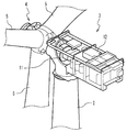
도 1은 본 발명의 일 실시 형태의 유성 기어 기구가 적용되어 있는 풍력 발전 장치의 구성을 도시하는 외관도이다.
도 2는 본 발명의 일 실시 형태에 있어서의 너셀 내부의 구조를 도시하는 조감도이다.
도 3은 본 발명의 일 실시 형태에 있어서의 증속기의 구조를 도시하는 단면도이다.
도 4는 본 발명의 일 실시 형태에 있어서의 유성 기어의 구조를 도시하는 정면도이다.
도 5는 본 발명의 일 실시 형태에 있어서의 유성 기어의 구조를 도시하는 단면도이다.
도 6은 본 발명의 일 실시 형태에 있어서의 중간 하우징의 구조를 도시하는 부분 단면도이다.BRIEF DESCRIPTION OF THE DRAWINGS It is an external view which shows the structure of the wind turbine generator to which the planetary gear mechanism of one Embodiment of this invention is applied.
FIG. 2 is a bird's eye view showing a structure inside a nussel in one embodiment of the present invention. FIG.
It is sectional drawing which shows the structure of the speed increaser in one Embodiment of this invention.
It is a front view which shows the structure of the planetary gear in one Embodiment of this invention.
It is sectional drawing which shows the structure of the planetary gear in one Embodiment of this invention.
6 is a partial cross-sectional view showing the structure of an intermediate housing in one embodiment of the present invention.
도 1은 본 발명의 일 실시 형태의 유성 기어 기구가 적용되어 있는 풍력 발전 장치의 구성을 도시하는 외관도이다. 풍력 발전 장치(1)는, 기초(6)에 세워진 지주(2)와, 지주(2)의 상단부에 설치되는 너셀(3)과, 너셀(3)에 대하여 회전 가능하게 설치된 로터 헤드(4)와, 로터 헤드(4)에 설치되는 풍차 블레이드(5)를 구비하고 있다. 로터 헤드(4)와 풍차 블레이드(5)에 의해, 풍차 로터가 구성되어 있다.BRIEF DESCRIPTION OF THE DRAWINGS It is an external view which shows the structure of the wind turbine generator to which the planetary gear mechanism of one Embodiment of this invention is applied. The wind turbine generator 1 includes a
도 2에 도시되어 있는 바와 같이, 너셀(3)의 내부에는, 증속기(11)와, 발전기(12)가 설치되어 있다. 증속기(11)의 입력축은 로터 헤드(4)의 주축(도시 생략)에 접합되어 있고, 증속기(11)의 출력축은, 발전기(12)의 로터에 접합되어 있다. 풍력에 의해 로터 헤드(4)가 회전하면, 그 회전이 증속기(11)에 의해 증속되어 발전기(12)의 로터에 전달되어, 발전기(12)가 구동된다. 이에 의해, 발전기(12)로부터 전력이 얻어진다.As shown in FIG. 2, the speed increaser 11 and the
도 3은 증속기(11)의 구성을 도시하는 단면도이다. 증속기(11)는, 유성 기어 기구(13)와, 평행축 기어 증속 기구(14)와, 그들을 수납하는 하우징(15)을 구비하고 있다. 유성 기어 기구(13)는, 태양 기어(21)와, 복수의 유성 기어(22)(1개만 도시)와, 내기어(23)와, 복수의 유성 핀(24)(1개만 도시)과, 캐리어(25)와, 유성 출력축(26)을 구비하고 있다. 유성 기어(22)는, 태양 기어(21)와 내기어(23) 사이에 위치하고 있고, 유성 기어(22)에 삽입된 유성 핀(24)에 의해 캐리어(25)에 지지되어 있다. 후술하는 바와 같이, 유성 기어(22)에 형성된 삽입 구멍의 내주면에는 미끄럼 베어링이 설치되어 있고, 유성 기어(22)는, 유성 핀(24)에 대하여 회전 가능하다. 캐리어(25)는, 하우징(15)에 설치된 베어링(27)에 의해 회전 가능하게 지지되어 있고, 유성 기어 기구(13)의 입력축, 즉, 증속기(11)의 입력축으로서 사용된다. 한편, 유성 출력축(26)은, 태양 기어(21)에 결합되어, 유성 기어 기구(13)의 출력축으로서 사용된다. 캐리어(25)가 회전되면, 그 회전이, 유성 기어(22)를 통하여 태양 기어(21)에 전달되고, 태양 기어(21)에 접속된 유성 출력축(26)이 증속되어 회전한다.3 is a cross-sectional view showing the configuration of the
평행축 기어 증속 기구(14)는, 유성 출력축(26)에 접합되는 제1 회전축(31)과, 제1 회전축(31)에 접합되는 제1 헬리컬 기어(32)와, 제2 헬리컬 기어(33)와, 제2 헬리컬 기어(33)에 접합되는 제2 회전축(34)과, 제2 회전축(34)에 접합되는 제3 헬리컬 기어(35)와, 제4 헬리컬 기어(36)와, 제4 헬리컬 기어(35)에 접합되는 출력축(37)을 구비하고 있다. 제1 회전축(31), 제2 회전축(34) 및 출력축(37)은, 각각, 하우징(15)에 설치된 베어링(38, 39, 40)에 의해 회전 가능하게 지지되어 있다. 또한, 제1 헬리컬 기어(32)와 제2 헬리컬 기어(33)는 맞물려 있고, 제3 헬리컬 기어(35)와 제4 헬리컬 기어(36)는 맞물려 있다. 이와 같은 구조의 평행축 기어 증속 기구(14)에서는, 유성 출력축(26)이 회전되면, 그 회전이, 제1 헬리컬 기어(32), 제2 헬리컬 기어(33), 제3 헬리컬 기어(35) 및 제4 헬리컬 기어(36)에 전달되고, 제4 헬리컬 기어(36)에 접속된 출력축(37)이 증속되어 회전한다. 즉, 증속기(11) 전체에서는, 캐리어(25)가 회전하면, 그 회전이 유성 기어 기구(13)와 평행축 기어 증속 기구(14)에 의해 증속되어 출력축(37)으로부터 출력되게 된다.The parallel shaft
본 실시 형태의 유성 기어 기구(13)에서는, 유성 기어(22)의 내주에 미끄럼 베어링이 설치되어 있고, 이 미끄럼 베어링에 의해 유성 기어(22)가 유성 핀(24)에 의해 회전 가능하게 지지되어 있다. 상술한 바와 같이, 미끄럼 베어링을 사용하는 것은, 베어링이 견딜 수 있는 하중의 증대와 장기 수명화에 유용하지만, 내하중이 큰 미끄럼 베어링은, 성형 가능한 형상에 제약이 있다. 본 실시 형태의 유성 기어 기구(13)의 특징 중 하나는, 성형 가능한 형상에 제약이 있는 미끄럼 베어링을 유성 기어(22)에 조립하는 것을 가능하게 하는 구조를 채용하고 있는 점에 있다. 이하, 유성 기어(22)의 구조에 대하여 상세하게 설명한다.In the
도 4는 본 실시 형태에서의 유성 기어(22)의 구조를 도시하는 정면도이고, 도 5는 단면도이다. 유성 기어(22)는, 개략적으로는, 외주면에 이가 형성된 기어 부재(41)와, 기어 부재(41)와는 다른 부재인 중간 하우징(42)과, 2개의 반원통형의 반할(半割) 미끄럼 베어링 부재(43)로 구성된다. 반원통형의 반할 미끄럼 베어링 부재(43)가 단부면(43d)에서 접합됨으로써, 원통형의 미끄럼 베어링이 형성되어 있다. 이 미끄럼 베어링에 유성 핀(24)이 삽입된다.4 is a front view showing the structure of the
본 실시 형태에서는, 반할 미끄럼 베어링 부재(43)는, 수지 재료(예를 들어 PEEK재)로 구성된 표면층(43a)이 배킹 메탈(43b)에 의해 백킹된 구조를 갖고 있다. 상술한 바와 같이, 수지 재료로 구성된 표면층이 배킹 메탈에 의해 백킹된 구조는 원통형으로 성형하는 것이 곤란하므로, 본 실시 형태에서는, 미끄럼 베어링을 2개의 반원통형의 반할 미끄럼 베어링 부재(43)로 분할한 구조가 채용되고 있다.In the present embodiment, the half sliding bearing
반할 미끄럼 베어링 부재(43)를 유성 기어(22)에 조립하기 위해서, 하기와 같은 구조가 채용되고 있다. 기어 부재(41)에는 관통 구멍이 형성되어 있고, 그 관통 구멍에 중간 하우징(42)이 끼워 넣어져 있다. 본 실시 형태에서는, 중간 하우징(42)은, 기어 부재(41)의 관통 구멍에 수축 끼워 맞춤에 의해 끼워 넣어져 있어, 중간 하우징(42)은 기어 부재(41)와 탈착 가능하다. 반할 미끄럼 베어링 부재(43)는, 중간 하우징(42)의 내주면에 접합되어 있다. 본 실시 형태에서는, 반할 미끄럼 베어링 부재(43)의 배킹 메탈(43b)이 중간 하우징(42)에 레이저 스폿 용접에 의해 용접되어 있다. 도 4에는, 배킹 메탈(43b)이 중간 하우징(42)에 용접되는 용접 위치가 부호 43c에 의해 나타내어져 있다.In order to assemble the sliding bearing
게다가, 본 실시 형태에서는, 중간 하우징(42)의 캐리어(25)와 대향하는 면에 스러스트 베어링이 설치되어 있다. 구체적으로는, 중간 하우징(42)의 캐리어(25)와 대향하는 면에 환 형상의 홈(42a)이 형성되고, 그 홈(42a)에 원호 형상의 복수의 스러스트 세그먼트(44)가, 환 형상으로, 상세하게는 둘레 방향으로 등간격으로 나란히 설치되어 있다. 한편, 도 3에 도시되어 있는 바와 같이, 캐리어(25)의 유성 기어(22)에 대향하는 면에는 링 형상의 스러스트 칼라(28)가 설치되어 있고, 유성 핀(24)은, 스러스트 칼라(28)에 통과되어 있다. 복수의 스러스트 세그먼트(44)와 스러스트 칼라(28)에 의해 유성 기어(22)를 스러스트 방향으로 지지하는 스러스트 베어링이 구성되어 있다. 본 실시 형태에서는 16개의 스러스트 세그먼트(44)가 형성되어 있다. 스러스트 세그먼트(44)는, 서로 이격되어 배치되어 있다. 스러스트 세그먼트(44)가 이격되어 배치되어 있는 것은, 반할 미끄럼 베어링 부재(43)와 유성 핀(24) 사이에 윤활유를 공급 또는 배출하는 경로를 제공하는 관점에서 유용하다. 이와 같은 구조에서는, 인접하는 스러스트 세그먼트(44)의 사이의 간극이 윤활유가 통과하는 경로로서 기능한다.In addition, in this embodiment, the thrust bearing is provided in the surface which opposes the
또한, 스러스트 칼라(28)는, 스러스트 베어링을 구성하는 부재로서 반드시 필요한 것은 아니다. 스러스트 칼라(28)를 설치하는 대신에, 캐리어(25)의 스러스트 세그먼트(44)에 대향하는 부분을 연마 가공해도 된다.In addition, the
도 6은 스러스트 세그먼트(44)를 중간 하우징(42)에 설치하는 구조를 도시하는 부분 단면도이다. 스러스트 세그먼트(44)는, 수지 재료(예를 들어 PEEK재)로 형성된 표면층(44a)과 배킹 메탈(44b)로 구성되어 있고, 스러스트 베어링은 미끄럼 베어링으로서 구성되어 있다. 각 스러스트 세그먼트(44)는, 핀(45)이 중간 하우징(42)과 스러스트 세그먼트(44)에 매립됨으로써 위치 결정되고, 중간 하우징(42)을 스러스트 세그먼트(44)를 향하여 코킹함으로써 고정되어 있다. 도 4, 도 6에 있어서, 중간 하우징(42)이, 코킹되어 변형되어 있는 변형 부분이, 부호 44c에 의해 나타내어져 있다. 중간 하우징(42)이 코킹됨으로써, 스러스트 세그먼트(44)가 중간 하우징(42)으로부터 이탈하는 것이 방지되어 있다. 또한, 중간 하우징(42)의 홈(42a)의 저면과 스러스트 세그먼트(44)의 이면에 구멍이 형성되고, 그 구멍에 핀(45)이 매립된다. 이에 의해, 스러스트 세그먼트(44)가 둘레 방향으로 이동하는 것이 방지되어 있다.6 is a partial cross-sectional view showing a structure in which the
반할 미끄럼 베어링 부재(43)를 직접적으로 기어 부재(41)에 조립하는 것이 아니라, 반할 미끄럼 베어링 부재(43)가 중간 하우징(42)에 조립된 후, 중간 하우징(42)이 기어 부재(41)에 조립되는 구조가 채용되고 있는 것이 중요하다. 반원통형의 반할 미끄럼 베어링 부재(43)는, 수축 끼워 맞춤에 의해 기어 부재(41)에 직접적으로 조립할 수는 없다. 한편, 반원통형의 반할 미끄럼 베어링 부재(43)를 직접적으로 기어 부재(41)에 용접하면, 미끄럼 베어링의 교환을 할 수 없게 되고, 또한 기어 부재(41)에 부분적으로 열이 가해져, 기어 부재(41)의 열변형을 초래할 수 있다. 본 실시 형태에서는, 기어 부재(41)와 반할 미끄럼 베어링 부재(43) 사이에 기어 부재(41)와 탈착 가능한 중간 하우징(42)을 삽입하는 구조를 채용함으로써, 기어 부재(41)의 열변형을 피함과 동시에, 반할 미끄럼 베어링 부재(43)가 교환 가능하게 된다.Rather than assembling the half
중간 하우징(42)을 삽입하는 것은, 유성 기어(22)의 제조의 TAT(turn around time)를 저감하기 위해서도 바람직하다. 기어 부재(41)와는 다른 부재인 중간 하우징(42)에 반할 미끄럼 베어링 부재(43) 및 스러스트 세그먼트(44)를 설치하는 구조에서는, 기어 부재(41)에 이를 형성하는 공정과, 중간 하우징(42)에 반할 미끄럼 베어링 부재(43) 및 스러스트 세그먼트(44)를 설치하는 공정을 병행하여 행하는 것이 가능하다. 이에 의해, 유성 기어(22)의 제조의 TAT를 저감할 수 있다.Inserting the
이상에 설명되어 있는 바와 같이, 본 실시 형태의 유성 기어 기구(13)에서는, 반할 미끄럼 베어링 부재(43)가 중간 하우징(42)에 조립된 후, 중간 하우징(42)이 기어 부재(41)에 조립되는 구조가 채용되고 있다. 이에 의해, 성형 가능한 형상에 제약이 있는 미끄럼 베어링을 유성 기어의 베어링으로서 조립하는 구조가 실현되어 있다.As described above, in the
또한, 상술에는, 본 발명의 실시 형태가 구체적으로 설명되어 있지만, 본 발명은, 당업자에게는 자명적인 다양한 변형이 가능하다. 예를 들어, 본 실시 형태에서는 미끄럼 베어링이 2개의 반할 미끄럼 베어링 부재(43)로 구성되어 있지만, 미끄럼 베어링이, 둘레 방향으로 분할된 3 이상의 미끄럼 베어링 부재로 구성되어도 된다. 또한, 상기에는 풍력 발전 장치(1)의 증속기(11)에 유성 기어 기구가 적용된 실시 형태가 제시되어 있지만, 본 발명의 유성 기어 기구는, 유성 기어에 큰 하중이 걸리는 다른 동력 기계에도 적절하게 적용될 수 있다.In addition, although embodiment of this invention is described concretely in the above, this invention can be variously modified that is obvious to those skilled in the art. For example, in the present embodiment, the sliding bearing is composed of two half sliding bearing
Claims (13)
상기 유성 기어에 삽입되는 유성 핀을 구비하고,
상기 유성 기어는,
외주면에 이가 형성되며, 관통 구멍이 형성된 기어 부재와,
상기 관통 구멍에 삽입되며, 상기 유성 핀이 삽입되는 삽입 구멍이 형성되는 중간 하우징과,
상기 중간 하우징의 상기 삽입 구멍에 접합된 복수의 미끄럼 베어링 부재를 구비하고,
상기 복수의 미끄럼 베어링 부재가, 상기 유성 핀과 상기 유성 기어를 회전 가능하게 보유 지지하는 미끄럼 베어링을 구성하고 있는, 유성 기어 기구.With planetary gears,
And a planetary pin inserted into the planetary gear,
The planetary gear,
A tooth member formed on an outer circumferential surface thereof, the gear member having a through hole formed therein;
An intermediate housing inserted into the through hole and having an insertion hole into which the planetary pin is inserted;
A plurality of sliding bearing members joined to the insertion hole of the intermediate housing,
The planetary gear mechanism of the plurality of sliding bearing members constitutes a sliding bearing for rotatably holding the planetary pin and the planetary gear.
상기 중간 하우징과 상기 미끄럼 베어링 부재가 탈착 불가능하도록 접합되고,
상기 유성 기어와 상기 중간 하우징이 탈착 가능하도록 접합되어 있는, 유성 기어 기구.The method of claim 1,
The intermediate housing and the sliding bearing member are joined so as to be non-removable,
The planetary gear mechanism of the planetary gear and the intermediate housing are detachably joined.
상기 중간 하우징과 상기 미끄럼 베어링 부재가 용접되고,
상기 유성 기어와 상기 중간 하우징이 수축 끼워 맞춤에 의해 접합되어 있는, 유성 기어 기구.The method of claim 2,
The intermediate housing and the sliding bearing member are welded,
The planetary gear mechanism wherein the planetary gear and the intermediate housing are joined by shrink fit.
상기 유성 핀에 연결되는 캐리어를 더 구비하고,
상기 중간 하우징은, 상기 캐리어에 대향하는 면에 스러스트 베어링으로서 기능하는 적어도 하나의 스러스트 패드를 구비한, 유성 기어 기구.4. The method according to any one of claims 1 to 3,
Further comprising a carrier connected to the planetary pin,
And the intermediate housing has at least one thrust pad functioning as a thrust bearing on a surface opposite the carrier.
상기 스러스트 패드는 복수이고,
상기 스러스트 패드는, 서로 이격되어 환 형상으로 배치되어 있는, 유성 기어 기구.The method of claim 4, wherein
The thrust pad is a plurality,
The thrust pads are spaced apart from each other and are disposed in a ring shape.
상기 중간 하우징의 상기 삽입 구멍에 접합된 복수의 미끄럼 베어링 부재를 구비하고,
상기 복수의 미끄럼 베어링 부재가 미끄럼 베어링을 구성하고 있는, 베어링 구조.An intermediate housing having an insertion hole into which a pin is inserted, which is inserted into a through hole formed in a gear member having teeth formed on an outer circumferential surface thereof;
A plurality of sliding bearing members joined to the insertion hole of the intermediate housing,
A bearing structure in which the plurality of sliding bearing members constitutes a sliding bearing.
상기 중간 하우징과 상기 미끄럼 베어링 부재가 탈착 불가능하도록 접합되고,
상기 기어 부재와 상기 중간 하우징이 탈착 가능하도록 접합되는, 베어링 구조.The method of claim 6,
The intermediate housing and the sliding bearing member are joined so as to be non-removable,
And the gear member and the intermediate housing are detachably joined.
상기 미끄럼 베어링 부재는,
수지 재료로 된 표면층과,
상기 표면층을 백킹하는 배킹 메탈을 구비하는, 베어링 구조.The method of claim 6,
The sliding bearing member,
A surface layer made of a resin material,
And a backing metal for backing said surface layer.
상기 중간 하우징은, 스러스트 베어링으로서 기능하는 적어도 하나의 스러스트 패드를 구비한, 베어링 구조.The method of claim 6,
The intermediate housing has at least one thrust pad functioning as a thrust bearing.
상기 로터 헤드에 연결된 입력축을 포함하는 증속기와,
상기 증속기의 출력축에 연결된 발전기를 구비하고,
상기 증속기가, 유성 기어 기구를 포함하고,
상기 유성 기어 기구가, 유성 기어와, 상기 유성 기어에 삽입되는 유성 핀을 구비하고,
상기 유성 기어는,
외주면에 기어가 형성되며, 관통 구멍이 형성된 기어 부재와,
상기 관통 구멍에 삽입되며, 상기 유성 핀이 삽입되는 삽입 구멍이 형성되는 중간 하우징과,
상기 중간 하우징의 상기 삽입 구멍에 접합되며, 상기 유성 핀의 둘레 방향으로 나란히 배치된 복수의 미끄럼 베어링 부재를 구비하고,
상기 복수의 미끄럼 베어링 부재가, 상기 유성 핀과 상기 유성 기어를 회전 가능하게 보유 지지하는 미끄럼 베어링을 구성하고 있는, 풍력 발전 장치.A windmill rotor comprising a rotor head and a windmill blade coupled to the rotor head;
An increaser including an input shaft connected to the rotor head;
A generator connected to the output shaft of the speed increaser,
The speed reducer includes a planetary gear mechanism,
The planetary gear mechanism includes a planetary gear and a planetary pin inserted into the planetary gear,
The planetary gear,
Gear member is formed on the outer circumferential surface, the through-hole formed gear member,
An intermediate housing inserted into the through hole and having an insertion hole into which the planetary pin is inserted;
A plurality of sliding bearing members joined to the insertion hole of the intermediate housing and arranged side by side in the circumferential direction of the planetary pin,
The plurality of sliding bearing members constitutes a sliding bearing for rotatably holding the planetary pin and the planetary gear.
상기 삽입 구멍이 형성된 중간 하우징을 제공하는 공정과,
상기 중간 하우징의 상기 삽입 구멍에, 미끄럼 베어링을 구성하는 복수의 미끄럼 베어링 부재를 접합하는 공정과,
외주면에 이가 형성된 기어 부재의 관통 구멍에, 상기 중간 하우징을 끼워 넣는 공정을 구비하는, 유성 기어의 제조 방법.A manufacturing method of a planetary gear having a structure in which a planetary pin passes through an insertion hole of a planetary gear mechanism,
Providing an intermediate housing in which the insertion hole is formed;
Bonding a plurality of sliding bearing members constituting the sliding bearing to the insertion hole of the intermediate housing;
The manufacturing method of the planetary gear which comprises the process of fitting the said intermediate housing in the through-hole of the gear member in which the tooth was formed in the outer peripheral surface.
상기 중간 하우징과 상기 미끄럼 베어링 부재가 탈착 불가능하도록 접합되고,
상기 유성 기어와 상기 중간 하우징이 탈착 가능하도록 접합되는, 유성 기어의 제조 방법.The method of claim 11,
The intermediate housing and the sliding bearing member are joined so as to be non-removable,
The planetary gear manufacturing method, wherein the planetary gear and the intermediate housing are detachably joined.
상기 중간 하우징과 상기 미끄럼 베어링 부재가 용접되고,
상기 유성 기어와 상기 중간 하우징이 수축 끼워 맞춤에 의해 접합되는, 유성 기어의 제조 방법.The method of claim 12,
The intermediate housing and the sliding bearing member are welded,
And the planetary gear and the intermediate housing are joined by shrink fit.
Applications Claiming Priority (1)
| Application Number | Priority Date | Filing Date | Title |
|---|---|---|---|
| PCT/JP2010/064788 WO2012029121A1 (en) | 2010-08-31 | 2010-08-31 | Planetary gear mechanism, bearing structure, wind power generator, and method for producing planetary gears |
Publications (1)
| Publication Number | Publication Date |
|---|---|
| KR20120054559A true KR20120054559A (en) | 2012-05-30 |
Family
ID=45697522
Family Applications (1)
| Application Number | Title | Priority Date | Filing Date |
|---|---|---|---|
| KR1020117012286A Abandoned KR20120054559A (en) | 2010-08-31 | 2010-08-31 | Planetary gear train, bearing structure, wind turbine generator, and manufacture method of planetary gear |
Country Status (8)
| Country | Link |
|---|---|
| US (1) | US20120051915A1 (en) |
| JP (1) | JPWO2012029121A1 (en) |
| KR (1) | KR20120054559A (en) |
| CN (1) | CN102575750A (en) |
| AU (1) | AU2010276474A1 (en) |
| BR (1) | BRPI1005388A2 (en) |
| CA (1) | CA2730096C (en) |
| WO (1) | WO2012029121A1 (en) |
Families Citing this family (28)
| Publication number | Priority date | Publication date | Assignee | Title |
|---|---|---|---|---|
| EP2732158A1 (en) * | 2011-07-15 | 2014-05-21 | ZF Wind Power Antwerpen N.V. | Nacelle main frame structure and drive train assembly for a wind turbine |
| JP5622716B2 (en) * | 2011-12-28 | 2014-11-12 | 三菱重工業株式会社 | Planetary gear device and wind power generator |
| AT512436B1 (en) * | 2012-01-16 | 2013-10-15 | Miba Gleitlager Gmbh | WIND TURBINE |
| KR20130110266A (en) * | 2012-03-29 | 2013-10-10 | 삼성중공업 주식회사 | Windmill and pitch bearing thereof |
| AT513516B1 (en) * | 2013-01-30 | 2014-05-15 | Miba Gleitlager Gmbh | Wind Turbine Gearbox |
| AT513743B1 (en) | 2013-01-30 | 2014-07-15 | Miba Gleitlager Gmbh | Wind Turbine Gearbox |
| US20160146112A1 (en) * | 2013-06-28 | 2016-05-26 | General Electric Company | Lightweight gear assembly for epicyclic gearbox |
| DE102013221265A1 (en) * | 2013-10-21 | 2015-05-07 | Schaeffler Technologies Gmbh & Co. Kg | Planetary wheel bearing assembly |
| EP2884124B1 (en) * | 2013-12-16 | 2017-06-28 | Areva Wind GmbH | Bidirectional bearing, drive train, planetary gear and wind generator |
| CN104265864A (en) * | 2014-09-17 | 2015-01-07 | 常熟市华德粉末冶金有限公司 | Powder metallurgical planetary gear for high-power starter |
| AT517719B1 (en) * | 2015-09-15 | 2017-04-15 | Miba Gleitlager Austria Gmbh | Planetary gear for a wind turbine |
| CN109563814B (en) * | 2016-08-04 | 2020-06-23 | 弗兰德有限公司 | wind drive |
| EP3351830B2 (en) * | 2017-01-23 | 2023-03-15 | Flender GmbH | Planetary transmission with improved planet carrier bearing |
| CN108661864B (en) | 2017-03-29 | 2022-03-22 | 通用电气公司 | Repair method for gearbox assembly for wind turbine |
| AT519938B1 (en) | 2017-04-26 | 2019-02-15 | Miba Gleitlager Austria Gmbh | Method for producing a plain bearing bush |
| JP2019123496A (en) * | 2018-01-16 | 2019-07-25 | Ntn株式会社 | In-wheel motor driving device |
| AT521071B1 (en) | 2018-03-23 | 2019-12-15 | Miba Gleitlager Austria Gmbh | Wind turbine transmission and method for producing a wind turbine transmission |
| DE102018120810A1 (en) * | 2018-08-27 | 2020-02-27 | Renk Aktiengesellschaft | Bearing arrangement of a rotor of a wind turbine and wind turbine |
| EP3906367B1 (en) * | 2018-12-31 | 2024-04-10 | Saint-Gobain Performance Plastics Pampus GmbH | Strut bearing, assembly, and method of making and using the same |
| US11174895B2 (en) * | 2019-04-30 | 2021-11-16 | General Electric Company | Bearing for a wind turbine drivetrain having an elastomer support |
| CN110671487B (en) * | 2019-09-30 | 2023-03-14 | 重庆长安汽车股份有限公司 | Well even board and car of hybrid transmission |
| CN111043280B (en) * | 2020-01-19 | 2022-11-11 | 常州锝莱电机有限公司 | Split type miniature planetary reduction gearbox and assembly tool thereof |
| DE102020203240A1 (en) * | 2020-03-13 | 2021-05-20 | Zf Friedrichshafen Ag | Laser deposition welding for highly stressed areas of a planetary bearing |
| WO2022061707A1 (en) * | 2020-09-25 | 2022-03-31 | 舍弗勒技术股份两合公司 | Dynamic pressure sliding bearing assembly and dynamic pressure sliding bearing unit |
| CN113414568B (en) * | 2021-07-16 | 2022-09-30 | 重庆齿轮箱有限责任公司 | Multi-type single-arm planet shaft press-fitting platform |
| CN115111345B (en) * | 2022-08-22 | 2023-01-24 | 太原科技大学 | Wind power speed-up gear box with radial/thrust sliding bearing combined supporting structure |
| DE102022133382A1 (en) * | 2022-12-15 | 2024-06-20 | Schaeffler Technologies AG & Co. KG | Planetary gear and wind turbine |
| DE102023211389A1 (en) * | 2023-11-16 | 2025-05-22 | Zf Friedrichshafen Ag | Axial plain bearings with rigid sliding segments |
Family Cites Families (34)
| Publication number | Priority date | Publication date | Assignee | Title |
|---|---|---|---|---|
| US3111261A (en) * | 1960-05-02 | 1963-11-19 | Curtiss Wright Corp | Rotor and bearing construction for rotary mechanisms |
| US3305325A (en) * | 1964-10-21 | 1967-02-21 | Federal Mogul Corp | Bearing and method of making same |
| US3376183A (en) * | 1964-05-05 | 1968-04-02 | Federal Mogul Corp | Method of making a composite bearing material |
| US4325589A (en) * | 1977-01-21 | 1982-04-20 | Carl Hurth Maschinen- Und Zahnradfabrik Gmbh & Co. | Support of a machine part which rotates on a bolt or the like |
| JPS58134253A (en) * | 1982-02-03 | 1983-08-10 | Hitachi Constr Mach Co Ltd | Planetary gear device |
| JPS60142319U (en) * | 1984-02-29 | 1985-09-20 | キ−パ−株式会社 | Segment type rubber bearing |
| US4784068A (en) * | 1987-07-24 | 1988-11-15 | Zeftek, Inc. | Segmented sliding sill wear plate |
| JP2532583B2 (en) | 1988-06-09 | 1996-09-11 | 松下電子工業株式会社 | Solid-state imaging device |
| JPH0233961U (en) * | 1988-08-29 | 1990-03-05 | ||
| JP2820436B2 (en) * | 1989-06-20 | 1998-11-05 | 三菱重工業株式会社 | Intermediate bearing structure for marine contra-rotating propeller shaft |
| JP2605892B2 (en) * | 1989-10-23 | 1997-04-30 | 日産自動車株式会社 | Plain bearing |
| US5242717A (en) * | 1990-12-27 | 1993-09-07 | Daido Metal Company Ltd. | Method of producing a composite sliding member |
| JPH05202939A (en) * | 1992-01-30 | 1993-08-10 | Hitachi Ltd | Ceramic bearing |
| JPH09112564A (en) * | 1995-10-17 | 1997-05-02 | Toshiba Corp | Sliding bearing of rotating electric machine |
| JPH1047443A (en) * | 1996-07-31 | 1998-02-20 | Hitachi Constr Mach Co Ltd | Planetary gear reducer |
| JPH10246231A (en) * | 1997-03-06 | 1998-09-14 | Hitachi Constr Mach Co Ltd | Plain bearing assembly |
| JP3432707B2 (en) * | 1997-06-24 | 2003-08-04 | 株式会社荏原製作所 | Plain bearing |
| US6024494A (en) * | 1998-02-12 | 2000-02-15 | Ingersoll-Dresser Pump Company | Polymer-backed thrust bearings |
| JP2000266040A (en) * | 1999-03-16 | 2000-09-26 | Eagle Ind Co Ltd | Slide bearing |
| JP2001208047A (en) * | 2000-01-24 | 2001-08-03 | Eagle Ind Co Ltd | Slide bearing |
| JP2002188637A (en) * | 2000-12-21 | 2002-07-05 | Hitachi Ltd | Bearing device, pump device and pump equipment |
| US7008348B2 (en) * | 2003-02-18 | 2006-03-07 | General Electric Company | Gearbox for wind turbine |
| FR2853382B1 (en) * | 2003-04-04 | 2006-04-28 | Hispano Suiza Sa | FLEXIBLE BONDING SYSTEM BETWEEN A SATELLITE HOLDER AND THE FIXED SUPPORT IN A SPEED REDUCER |
| WO2005005866A1 (en) * | 2003-07-02 | 2005-01-20 | The Timken Company | Transmission containing helical gearing and bearing arrangement therefor |
| CN101701321B (en) * | 2003-07-31 | 2014-03-19 | 株式会社小松制作所 | Sintered sliding member |
| US7416696B2 (en) * | 2003-10-03 | 2008-08-26 | Keystone Investment Corporation | Powder metal materials and parts and methods of making the same |
| EP1571334A1 (en) * | 2004-03-04 | 2005-09-07 | Gamesa Eolica, S.A. (Sociedad Unipersonal) | Wind turbine yawing system and yawing process |
| US7703983B2 (en) * | 2004-06-10 | 2010-04-27 | Ntn Corporation | Sliding material and sliding bearing |
| US20070275816A1 (en) * | 2006-05-26 | 2007-11-29 | Windflow Technology Ltd. | Noise reduction in epicyclic gear systems |
| US8220153B2 (en) * | 2006-05-26 | 2012-07-17 | Hitachi Powdered Metals Co., Ltd. | Production method for complex bearing |
| BE1017866A3 (en) * | 2007-12-06 | 2009-09-01 | Hansen Transmissions Int | WIND TURBINE DRIVE. |
| JP2009144532A (en) * | 2007-12-11 | 2009-07-02 | Mitsubishi Heavy Ind Ltd | Wind turbine generator |
| JP2010156360A (en) * | 2008-12-26 | 2010-07-15 | Mitsubishi Heavy Ind Ltd | Bearing device and rotary machine |
| CN101581284B (en) * | 2009-06-23 | 2012-02-15 | 吴小杰 | Megawatt sliding bearing wind power speed increasing box |
-
2010
- 2010-08-31 AU AU2010276474A patent/AU2010276474A1/en not_active Abandoned
- 2010-08-31 CA CA2730096A patent/CA2730096C/en not_active Expired - Fee Related
- 2010-08-31 CN CN2010800033077A patent/CN102575750A/en active Pending
- 2010-08-31 WO PCT/JP2010/064788 patent/WO2012029121A1/en not_active Ceased
- 2010-08-31 JP JP2011506280A patent/JPWO2012029121A1/en active Pending
- 2010-08-31 BR BRPI1005388A patent/BRPI1005388A2/en not_active IP Right Cessation
- 2010-08-31 KR KR1020117012286A patent/KR20120054559A/en not_active Abandoned
-
2011
- 2011-02-10 US US13/024,734 patent/US20120051915A1/en not_active Abandoned
Also Published As
| Publication number | Publication date |
|---|---|
| US20120051915A1 (en) | 2012-03-01 |
| BRPI1005388A2 (en) | 2016-08-16 |
| CA2730096C (en) | 2013-10-08 |
| JPWO2012029121A1 (en) | 2013-10-28 |
| AU2010276474A1 (en) | 2012-03-15 |
| CN102575750A (en) | 2012-07-11 |
| CA2730096A1 (en) | 2012-02-29 |
| WO2012029121A1 (en) | 2012-03-08 |
Similar Documents
| Publication | Publication Date | Title |
|---|---|---|
| KR20120054559A (en) | Planetary gear train, bearing structure, wind turbine generator, and manufacture method of planetary gear | |
| JP5622716B2 (en) | Planetary gear device and wind power generator | |
| JP5345048B2 (en) | Wind power transmission and wind power generator | |
| JP6165845B2 (en) | Planetary gear stage having a plain bearing as a planetary bearing and use thereof | |
| US20120177311A1 (en) | Planet bearing structure | |
| JPWO2012029129A1 (en) | Planetary gear mechanism, wind power generator, and carrier manufacturing method for planetary gear mechanism | |
| JP6575944B2 (en) | Journal bearing and method to facilitate optimization of fluid dynamic oil flow, load capacity, and bearing performance | |
| CN108953579B (en) | Drives especially for wind turbines | |
| JP6155713B2 (en) | One-way clutch for wind power generator and wind power generator | |
| JP4708221B2 (en) | Cylindrical roller bearing for wind power generator | |
| JP6142587B2 (en) | Clutch unit and wind power generator | |
| JP6758845B2 (en) | Eccentric swing type gear device | |
| WO2017086153A1 (en) | Bearing device and rotary machine | |
| JP6090502B2 (en) | One-way clutch and power generator | |
| JP2014173698A (en) | Assembling method of clutch unit | |
| JP2013148138A (en) | Planetary bearing structure | |
| EP4678911A1 (en) | Wind turbine gearbox and method of mounting a wind turbine gearbox | |
| JP7607543B2 (en) | Flexible mesh gear device | |
| JP6398183B2 (en) | Shaft coupling device and wind power generator | |
| JP2020051435A (en) | Slide bearing for planetary gear | |
| JP6064690B2 (en) | Wind power generator | |
| JP6142588B2 (en) | Wind power generator | |
| JP2014173545A (en) | Shaft coupling device and wind power generation device | |
| JP2016200173A (en) | One-way clutch unit and power generator |
Legal Events
| Date | Code | Title | Description |
|---|---|---|---|
| A201 | Request for examination | ||
| PA0105 | International application |
Patent event date: 20110530 Patent event code: PA01051R01D Comment text: International Patent Application |
|
| PA0201 | Request for examination | ||
| PG1501 | Laying open of application | ||
| E902 | Notification of reason for refusal | ||
| PE0902 | Notice of grounds for rejection |
Comment text: Notification of reason for refusal Patent event date: 20121106 Patent event code: PE09021S01D |
|
| N231 | Notification of change of applicant | ||
| PN2301 | Change of applicant |
Patent event date: 20130507 Comment text: Notification of Change of Applicant Patent event code: PN23011R01D |
|
| E90F | Notification of reason for final refusal | ||
| PE0902 | Notice of grounds for rejection |
Comment text: Final Notice of Reason for Refusal Patent event date: 20130521 Patent event code: PE09021S02D |
|
| E701 | Decision to grant or registration of patent right | ||
| PE0701 | Decision of registration |
Patent event code: PE07011S01D Comment text: Decision to Grant Registration Patent event date: 20131029 |
|
| NORF | Unpaid initial registration fee | ||
| PC1904 | Unpaid initial registration fee |