KR20120006100U - Circuit breaker - Google Patents
Circuit breaker Download PDFInfo
- Publication number
- KR20120006100U KR20120006100U KR2020110001490U KR20110001490U KR20120006100U KR 20120006100 U KR20120006100 U KR 20120006100U KR 2020110001490 U KR2020110001490 U KR 2020110001490U KR 20110001490 U KR20110001490 U KR 20110001490U KR 20120006100 U KR20120006100 U KR 20120006100U
- Authority
- KR
- South Korea
- Prior art keywords
- accessory
- nail
- circuit breaker
- protrusion
- circuit
- Prior art date
- Legal status (The legal status is an assumption and is not a legal conclusion. Google has not performed a legal analysis and makes no representation as to the accuracy of the status listed.)
- Granted
Links
Images


Classifications
-
- H—ELECTRICITY
- H01—ELECTRIC ELEMENTS
- H01H—ELECTRIC SWITCHES; RELAYS; SELECTORS; EMERGENCY PROTECTIVE DEVICES
- H01H71/00—Details of the protective switches or relays covered by groups H01H73/00 - H01H83/00
- H01H71/02—Housings; Casings; Bases; Mountings
- H01H71/0264—Mountings or coverplates for complete assembled circuit breakers, e.g. snap mounting in panel
- H01H71/0271—Mounting several complete assembled circuit breakers together
-
- H—ELECTRICITY
- H01—ELECTRIC ELEMENTS
- H01H—ELECTRIC SWITCHES; RELAYS; SELECTORS; EMERGENCY PROTECTIVE DEVICES
- H01H71/00—Details of the protective switches or relays covered by groups H01H73/00 - H01H83/00
- H01H71/10—Operating or release mechanisms
- H01H71/12—Automatic release mechanisms with or without manual release
- H01H71/128—Manual release or trip mechanisms, e.g. for test purposes
-
- H—ELECTRICITY
- H01—ELECTRIC ELEMENTS
- H01H—ELECTRIC SWITCHES; RELAYS; SELECTORS; EMERGENCY PROTECTIVE DEVICES
- H01H83/00—Protective switches, e.g. circuit-breaking switches, or protective relays operated by abnormal electrical conditions otherwise than solely by excess current
- H01H83/20—Protective switches, e.g. circuit-breaking switches, or protective relays operated by abnormal electrical conditions otherwise than solely by excess current operated by excess current as well as by some other abnormal electrical condition
-
- H—ELECTRICITY
- H01—ELECTRIC ELEMENTS
- H01H—ELECTRIC SWITCHES; RELAYS; SELECTORS; EMERGENCY PROTECTIVE DEVICES
- H01H71/00—Details of the protective switches or relays covered by groups H01H73/00 - H01H83/00
- H01H71/02—Housings; Casings; Bases; Mountings
- H01H71/0264—Mountings or coverplates for complete assembled circuit breakers, e.g. snap mounting in panel
- H01H71/0271—Mounting several complete assembled circuit breakers together
- H01H2071/0278—Mounting several complete assembled circuit breakers together with at least one of juxtaposed casings dedicated to an auxiliary device, e.g. for undervoltage or shunt trip
-
- H—ELECTRICITY
- H01—ELECTRIC ELEMENTS
- H01H—ELECTRIC SWITCHES; RELAYS; SELECTORS; EMERGENCY PROTECTIVE DEVICES
- H01H71/00—Details of the protective switches or relays covered by groups H01H73/00 - H01H83/00
- H01H71/02—Housings; Casings; Bases; Mountings
- H01H71/0207—Mounting or assembling the different parts of the circuit breaker
- H01H71/0228—Mounting or assembling the different parts of the circuit breaker having provisions for interchangeable or replaceable parts
-
- H—ELECTRICITY
- H01—ELECTRIC ELEMENTS
- H01H—ELECTRIC SWITCHES; RELAYS; SELECTORS; EMERGENCY PROTECTIVE DEVICES
- H01H83/00—Protective switches, e.g. circuit-breaking switches, or protective relays operated by abnormal electrical conditions otherwise than solely by excess current
- H01H83/12—Protective switches, e.g. circuit-breaking switches, or protective relays operated by abnormal electrical conditions otherwise than solely by excess current operated by voltage falling below a predetermined value, e.g. for no-volt protection
Landscapes
- Breakers (AREA)
- Switch Cases, Indication, And Locking (AREA)
Abstract
본 고안은 배선용 차단기에 관한 것으로서, 본 고안의 일측면에 의하면, 주 케이스, 상기 주 케이스의 내부에 수납되며 회로를 개폐하는 기구부를 가진 개폐기구와, 회로 상의 이상전류를 검출했을 때 상기 개폐기구를 회로 차단위치로 동작하도록 트리거하는 트립기구를 구비하는 배선용 차단기에 있어서, 상기 개폐기구에 포함되는 래치를 구속 또는 해제하는 래치 홀더; 상기 트립기구에 회전가능하게 장착되어 그 회전 방향에 따라서 상기 래치 홀더를 구속 또는 해제하는 네일; 및 상기 네일에 일체로 형성되는 돌기부;를 포함하며, 상기 돌기부는 상기 주 케이스에 부속장치가 장착위치로 접근하는 경우에는 부속장치와 접촉하여 상기 네일을 해제방향으로 회동시키고, 부속장치가 장착 위치에 배치되는 경우에는 부속장치와 접촉되지 않도록 형성되는 것을 특징으로 하는 배선용 차단기가 제공된다.The present invention relates to a circuit breaker, and according to one aspect of the present invention, an opening and closing mechanism having a main part, a mechanism part that is stored inside the main case to open and close a circuit, and the opening and closing mechanism when an abnormal current on a circuit is detected. A circuit breaker having a trip mechanism for triggering the operation to a circuit break position, the circuit breaker comprising: a latch holder for restraining or releasing a latch included in the opening / closing mechanism; A nail rotatably mounted to the trip mechanism to restrain or release the latch holder in accordance with the rotation direction thereof; And a protrusion formed integrally with the nail, wherein the protrusion rotates the nail in a release direction by contacting the accessory when the accessory approaches the mounting position of the main case. When arranged in the wiring breaker is provided, characterized in that it is formed so as not to contact the accessory.
Description
본 고안은 배선용 차단기에 관한 것으로서, 보다 구체적으로는 과전류나 이상전류가 흐르는 경우에 통전을 차단하는 배선용 차단기에 관한 것이다.The present invention relates to a circuit breaker, and more particularly, to a circuit breaker for interrupting energization when an overcurrent or an abnormal current flows.
일반적으로, 배선용 차단기는 공장, 빌딩 등의 수배전 설비 중에서 주로 배전반에 설치되어 무부하 상태에서는 부하측에 전원을 공급 또는 차단하는 개폐장치의 역할을 하고, 부하 사용중에는 부하전로에 이상 현상이 발생하여 부하 전류를 초과하는 대전류가 흐를 경우 전로의 전선 및 부하측 기기를 보호하기 위하여 전원측으로부터 부하측으로 공급되는 전원을 공급 또는 차단하는 차단기의 역할을 담당하게 된다.In general, wiring breakers are mainly installed in switchboards in factories, buildings, etc., and act as a switchgear that supplies or cuts power to the load side under no load condition. When a large current exceeding the load current flows in order to protect the electric wires and load-side equipment of the converter, it serves as a circuit breaker that supplies or cuts off the power supplied from the power supply side to the load side.
이와 같은 배선용 차단기는 프레임의 크기, 극수, 동작방식등이 상이하여 여러 가지 구조의 것이 제작되고 있으나, 몰드케이스?접촉자?트립장치?개폐기구 소호장치?단자 등을 기본적인 요소로 하여 구성된다.Such wiring breakers are manufactured in various structures due to different frame sizes, number of poles, operation methods, etc., but are mainly composed of a mold case, a contactor, a trip device, an opening / closing device extinguishing device, a terminal, and the like.
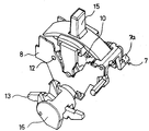
도 1은 종래의 배선용 차단기를 나타낸 사시도이고, 도 2는 도 1의 분해사시도이다. 한편, 도 3은 도 2의 개폐기구부 확대도이고, 도 4a 및 도 4b는 상기 개폐기구부의 동작을 설명하기 위한 개략도이다.1 is a perspective view illustrating a conventional circuit breaker, and FIG. 2 is an exploded perspective view of FIG. 1. 3 is an enlarged view of the opening and closing mechanism part of FIG. 2, and FIGS. 4A and 4B are schematic views for explaining the operation of the opening and closing mechanism part.
개폐용 핸들(15)을 투입시켜 차단기가 온(on)된 상태에서 트립버튼(3)을 이용하여 차단기를 트립시키고자 하는 경우, 도 4a에 화살표로 나타낸 바와 같이 트립버튼(3)의 헤드부에 누름력을 가하면, 보조커버(5)의 설치공(2)을 관통하여 설치된 트립버튼(3)이 하강하면서, 개폐기구부를 구성하는 네일(7)의 빗면(7a)을 누르게 된다.If the breaker is to be tripped using the
이에 따라, 사이드 플레이트(8)의 부하측 선단에 힌지결합된 네일(7)은 힌지축(6a)을 중심으로 도면상 시계방향으로 회전하여 4b에 나타낸 바와 같이 된다. 이 때, 래치홀더(9)에 홀딩되어 있던 래치(10)는 메인스프링(도시는 생략함)의 복원력에 의해 석방되어 회전중심(12)을 축으로 반시계방향으로 회동하게 되며, 이에 따라 링크기구의 연동작용에 의해 메인샤프트(16)에 설치된 가동접촉자(13)를 고정접촉자(14)로부터 이격시켜 차단기를 트립시키게 된다.Accordingly, the
한편, 상기와 같은 배선용 차단기에는 차단기의 온-오프-트립의 상태를 알려주는 보조스위치나, 경보스위치 등의 보조접점류와, 회로의 전압상태가 낮아질 때 동작하는 UVT(under voltage trip device), 원방에서 차단기를 트립시키는 션트(shunt) 트립 코일 등과 같은 외부 부속장치를 차단기 본체에 부착하여 사용하게 된다.On the other hand, the circuit breaker as described above includes an auxiliary switch for indicating the state of the on-off-trip of the circuit breaker, an auxiliary contact such as an alarm switch, and an under voltage trip device (UVT) operated when the voltage of the circuit is lowered, An external accessory such as a shunt trip coil that trips the breaker in the far place is attached to the breaker body.
이러한 부속장치들을 상기와 같은 종래의 배선용 차단기에 장착하기 위해서는 반드시 오프상태 및 트립상태에서 작업을 하여야 하는데, 사용자가 실수로 전원을 오프시키지 않고 작업을 하는 경우에는 안전사고가 발생될 수 있을 뿐만 아니라 상기 네일의 기구부와 부속장치와의 간섭 등에 의해 네일이 파손될 우려가 있다.In order to install such accessory devices in the conventional circuit breaker as described above, the work must be performed in the off state and the trip state, but if the user works without turning off the power by mistake, a safety accident may occur. There is a fear that the nail may be damaged due to interference between the mechanism part and the accessory of the nail.
본 고안은 상기와 같은 종래 기술의 단점을 극복하기 위해 안출된 것으로서, 부속장치 체결시에 실수로 차단기를 오프시키지 않더라도 부속장치가 체결되면 자동으로 차단기가 오프되도록 하는 배선용 차단기를 제공하는 것을 기술적 과제로 삼고 있다.The present invention has been made to overcome the disadvantages of the prior art as described above, the technical problem to provide a circuit breaker to automatically turn off the circuit breaker when the accessory is fastened even if you do not accidentally turn off the breaker when the accessory is fastened To be.
상기와 같은 기술적 과제를 달성하기 위한 본 고안의 일측면에 의하면, 주 케이스, 상기 주 케이스의 내부에 수납되며 회로를 개폐하는 기구부를 가진 개폐기구와, 회로 상의 이상전류를 검출했을 때 상기 개폐기구를 회로 차단위치로 동작하도록 트리거하는 트립기구를 구비하는 배선용 차단기에 있어서, 상기 개폐기구에 포함되는 래치를 구속 또는 해제하는 래치 홀더; 상기 트립기구에 회전가능하게 장착되어 그 회전 방향에 따라서 상기 래치 홀더를 구속 또는 해제하는 네일; 및 상기 네일에 일체로 형성되는 돌기부;를 포함하며, 상기 돌기부는 상기 주 케이스에 부속장치가 장착위치로 접근하는 경우에는 부속장치와 접촉하여 상기 네일을 해제방향으로 회동시키고, 부속장치가 장착 위치에 배치되는 경우에는 부속장치와 접촉되지 않도록 형성되는 것을 특징으로 하는 배선용 차단기가 제공된다.According to an aspect of the present invention for achieving the above technical problem, the main case, an opening and closing mechanism having a mechanism part for opening and closing the circuit and stored in the main case, and the opening and closing mechanism when detecting an abnormal current on the circuit A circuit breaker having a trip mechanism for triggering the operation to a circuit break position, the circuit breaker comprising: a latch holder for restraining or releasing a latch included in the opening / closing mechanism; A nail rotatably mounted to the trip mechanism to restrain or release the latch holder in accordance with the rotation direction thereof; And a protrusion formed integrally with the nail, wherein the protrusion rotates the nail in a release direction by contacting the accessory when the accessory approaches the mounting position of the main case. When arranged in the wiring breaker is provided, characterized in that it is formed so as not to contact the accessory.
본 고안의 상기 측면에서는 부속장치를 체결하기 위해서 상기 주 케이스 내에 배치하는 과정에서 상기 부속장치와 접촉하여 네일을 회동시키고, 그로 인해 차단기가 오프되도록 하는 돌기부를 형성하되, 상기 돌기부는 부속장치의 장착이 완료된 경우에는 네일이 원래의 기능을 수행할 수 있도록 부속장치와 접촉되지 않도록 한 것이다. 여기서, 장착 위치란 부속장치가 주 케이스에 대해서 체결이 완료된 상태에서의 부속장치의 위치를 의미한다.In the aspect of the present invention in order to fasten the accessory in the process of placing in the main case in contact with the accessory to rotate the nail, thereby forming a projection to turn off the breaker, the projection is mounted to the accessory If this is done, the nail is not in contact with the attachment to perform its original function. Here, the mounting position means the position of the accessory in a state where the accessory is fastened to the main case.
여기서, 상기 돌기부는 상기 네일의 일측으로부터 돌출되도록 형성되고, 상기 부속장치의 측면에는 상기 돌기부와 접촉하는 레버가 형성되되, 부속장치가 장착 위치에 배치된 경우에 상기 레버는 상기 돌기부의 하부에 배치되도록 할 수 있다.Here, the protrusion is formed to protrude from one side of the nail, the side of the accessory is formed with a lever in contact with the protrusion, when the accessory is disposed in the mounting position the lever is disposed below the protrusion You can do that.
이때, 상기 돌기부는 상기 네일의 일측으로부터 상향으로 경사지게 연장될 수 있다.In this case, the protrusion may extend inclined upward from one side of the nail.
상기와 같은 구성을 갖는 본 고안의 측면들에 의하면, 부속장치 체결시에 작업자가 착오 또는 실수로 차단기를 오프하지 않더라도 자동으로 차단기가 오프되므로 안전사고의 발생을 방지할 수 있을 뿐만 아니라 네일 등의 기구적 손상도 방지할 수 있게 된다.According to the aspects of the present invention having the configuration as described above, the breaker is automatically turned off even if the operator does not accidentally turn off the breaker when the accessory is fastened, not only to prevent the occurrence of safety accidents, such as nail Mechanical damage can also be prevented.
도 1은 종래의 배선용 차단기를 나타낸 사시도이다.
도 2는 도 1에 도시된 배선용 차단기의 분해사시도이다.
도 3은 도 2 중 개폐기구부를 확대하여 도시한 사시도이다.
도 4a는 도 1에 도시된 배선용 차단기에서 트립버튼이 하강하기 전의 상태를 도시한 개략도이다.
도 4b는 도 1에 도시된 배선용 차단기에서 트립버튼이 하강한 후의 상태를 도시한 개략도이다.
도 5는 본 고안에 따른 배선용 차단기의 일 실시예를 도시한 사시도이다.
도 6은 도 5에 도시된 실시예 중 트립기구부를 확대하여 도시한 사시도이다.
도 7 및 도 8은 도 5에 도시된 실시예의 작동과정을 개략적으로 도시한 사시도이다.1 is a perspective view showing a conventional circuit breaker.
FIG. 2 is an exploded perspective view of the circuit breaker shown in FIG. 1.
3 is an enlarged perspective view of the opening and closing mechanism of FIG. 2.
4A is a schematic diagram illustrating a state before the trip button descends in the circuit breaker shown in FIG. 1.
4B is a schematic diagram illustrating a state after the trip button is lowered in the circuit breaker shown in FIG. 1.
5 is a perspective view showing an embodiment of a circuit breaker according to the present invention.
6 is an enlarged perspective view of the trip mechanism part in the embodiment illustrated in FIG. 5.
7 and 8 are perspective views schematically showing the operation of the embodiment shown in FIG.
이하에서는 첨부된 도면을 참조하여, 본 고안에 따른 배선용 차단기의 실시예에 대해서 상세하게 설명하도록 한다.Hereinafter, with reference to the accompanying drawings, it will be described in detail an embodiment of a circuit breaker according to the present invention.
도 5는 본 고안에 따른 배선용 차단기의 일 실시예를 도시한 사시도이고, 도 6는 도 5에 도시된 실시예의 내부구조를 도시한 사시도이다. 도 5 및 도 6을 참조하면, 상기 실시예(100)는 직사각형 형태의 주 케이스(102)와 상기 주 케이스(102)를 덮는 커버(104)를 포함한다. 그리고, 상기 커버(104)에는 상술한 바와 같은 부속장치가 장착될 때 제거되는 보조커버(106)가 설치된다.5 is a perspective view showing an embodiment of a circuit breaker according to the present invention, Figure 6 is a perspective view showing the internal structure of the embodiment shown in FIG. 5 and 6, the
상기 보조커버(106)의 사이에는 사용자가 임의로 차단기를 조작할 수 있도록 하는 핸들(110)이 구비되어 있다. 그리고, 상기 핸들(110)의 하부에는 한 쌍의 고정 접촉자(112, 113)가 배치되어 있으며, 상기 고정 접촉자에 접촉 또는 분리되는 위치로 이동가능한 가동 접촉자(114)도 포함되게 된다. 상기 가동 접촉자(114)는 도시된 바와 같은 트립 기구부에 의해서 트립 동작이 수행되는 것으로서, 상기 트립 기구부의 작동 방식은 종래부터 알려진 것을 채용할 수 있으므로 그에 대한 상세한 설명은 생략하기로 한다.The
한편, 상기 핸들(110)의 좌우측으로 한 쌍의 측판(120)이 각각 배치되고, 상기 측판(120)은 상술한 트립기구부를 이루는 각종 구성요소들이 지지되는 베이스 역할을 하게 된다. 상기 측판의 후측(도 5에서는 우측)에 네일(130)이 상기 측판(120)에 대해서 회동가능하게 장착된다. 상기 네일(130)은 그 하부에 위치하는 래치의 회동을 구속할 수 있도록 배치되고 이에 따라, 상기 가동 접촉자가 회전이동되면서 상기 고정 접촉자와 접촉 또는 분리되게 된다.On the other hand, the pair of
상기 네일(130)은 구체적으로 상기 측판(120)에 고정되는 힌지축(132)과 상기 힌지축(132)의 양단에서 각각 연장되는 제1 및 제2 암(134, 136)을 포함하게 되는데, 상기 제1 암(134)의 단부 측면에는 상향으로 경사지게 연장되는 돌기부(138)가 형성되어 있다. 상기 돌기부(138)는 후술할 부속장치의 측면에 형성되는 레버와 연동되어 상기 네일(130)을 회동시켜서 차단기가 오프되도록 동작시키는 역할을 하게 된다.Specifically, the
도 7은 상기 실시예에 부속장치(140)가 장착되는 도중의 상태를 개략적으로 도시한 것으로서, 도 7을 참조하면, 상기 부속장치(140)의 측면으로부터 상기 돌기부(138)를 향하여 레버(142)가 돌출되도록 형성되어 있으며, 상기 레버(142)는 상기 실시예의 상부에서 보았을 때, 상기 돌기부(138)를 가로지르도록 연장된다.FIG. 7 schematically illustrates a state in which the
따라서, 도 7에 도시된 바와 같이, 상기 부속장치(140)를 설치할 때에는 상기 주 케이스에 대해서 하향으로 삽입하게 되는데, 이 과정에서 상기 레버(142)가 상기 돌기부(138)의 상부면과 접촉하게 된다. 부속장치(140)를 장착 위치까지 더 삽입하면 상기 레버(142)는 상기 돌기부(138)를 눌러서 상기 네일(130)이 상기 힌지축(132)을 중심으로 시계방향(도 7에서 화살표로 표시한 방향)으로 회전하게 된다.Therefore, as shown in FIG. 7, when the
즉, 상기 돌기부(138)의 상부면이 경사면으로 이루어지므로, 상기 레버(142)는 상기 경사면을 따라서 슬라이드되고, 이에 따라서 상기 네일(130)이 반시계 방향으로 회전하면서, 상기 래치를 해제하여 차단기가 오프되도록 구동하는 것이다. 그 후, 상기 부속장치를 장착 위치에 완전하게 위치시키면, 상기 레버(142)는 상기 돌기부(138) 상측면의 후단부를 통과하면서 레버와 돌기부 사이의 접촉이 해제되므로, 상기 네일(130)은 원래의 위치로 복귀하게 된다.That is, since the upper surface of the
이때, 상기 레버(142)는 부속장치가 장착 위치에 있는 경우에는 상기 돌기부(138)의 하부에 배치되므로, 네일이 회동하여도 상기 돌기부와 레버가 접촉되는 것이 방지된다.In this case, the
따라서, 작업자가 차단기가 온 상태인 경우에 부속장치를 장착하더라도, 상기 레버와 돌기부 사이의 상호작용으로 인해서 상기 네일이 차단기를 오프시키게 되므로 안전사고의 발생 및 네일의 손상을 최소화할 수 있게 된다.Therefore, even when the worker installs the accessory device when the breaker is in the ON state, the nail is turned off due to the interaction between the lever and the protrusion, thereby minimizing the occurrence of a safety accident and damage to the nail.
Claims (3)
상기 개폐기구에 포함되는 래치를 구속 또는 해제하는 래치 홀더;
상기 트립기구에 회전가능하게 장착되어 그 회전 방향에 따라서 상기 래치 홀더를 구속 또는 해제하는 네일; 및
상기 네일에 일체로 형성되는 돌기부;를 포함하며,
상기 돌기부는 상기 주 케이스에 부속장치가 장착위치로 접근하는 경우에는 부속장치와 접촉하여 상기 네일을 해제방향으로 회동시키고, 부속장치가 장착 위치에 배치되는 경우에는 부속장치와 접촉되지 않도록 형성되는 것을 특징으로 하는 배선용 차단기.A wiring breaker having a main case, an opening / closing mechanism housed in the main case and having a mechanism for opening and closing a circuit, and a tripping mechanism for triggering the opening / closing mechanism to operate in a circuit breaking position when an abnormal current on the circuit is detected. In
A latch holder for restraining or releasing a latch included in the opening / closing mechanism;
A nail rotatably mounted to the trip mechanism to restrain or release the latch holder in accordance with the rotation direction thereof; And
And a protrusion formed integrally with the nail.
The protruding portion is formed to be in contact with the accessory when the accessory is approached to the main case to rotate the nail in the release direction, and not to contact the accessory when the accessory is placed in the mounting position. The circuit breaker characterized by the above-mentioned.
상기 돌기부는 상기 네일의 일측으로부터 돌출되도록 형성되고, 상기 부속장치의 측면에는 상기 돌기부와 접촉하는 레버가 형성되되, 부속장치가 장착 위치에 배치된 경우에 상기 레버는 상기 돌기부의 하부에 배치되는 것을 특징으로 하는 배선용 차단기.The method of claim 1,
The protrusion is formed to protrude from one side of the nail, the side of the accessory is formed with a lever in contact with the protrusion, when the accessory is disposed in the mounting position the lever is disposed below the protrusion The circuit breaker characterized by the above-mentioned.
상기 돌기부는 상기 네일의 일측으로부터 상향으로 경사지게 연장되는 것을 특징으로 하는 배선용 차단기.The method of claim 2,
The protruding portion is a circuit breaker, characterized in that extending inclined upward from one side of the nail.
Priority Applications (8)
| Application Number | Priority Date | Filing Date | Title |
|---|---|---|---|
| KR2020110001490U KR200477244Y1 (en) | 2011-02-22 | 2011-02-22 | Circuit breaker |
| US13/364,220 US8796573B2 (en) | 2011-02-22 | 2012-02-01 | Circuit breaker |
| JP2012024976A JP5426702B2 (en) | 2011-02-22 | 2012-02-08 | Circuit breaker for wiring |
| EP12155546.0A EP2492944B1 (en) | 2011-02-22 | 2012-02-15 | Circuit breaker |
| ES12155546.0T ES2532951T3 (en) | 2011-02-22 | 2012-02-15 | Circuit breaker |
| RU2012106333/07A RU2490747C1 (en) | 2011-02-22 | 2012-02-21 | Circuit breaker |
| BR102012006885-0A BR102012006885B1 (en) | 2011-02-22 | 2012-02-22 | CIRCUIT BREAKER |
| CN201210047039.XA CN102651292B (en) | 2011-02-22 | 2012-02-22 | Circuit breaker |
Applications Claiming Priority (1)
| Application Number | Priority Date | Filing Date | Title |
|---|---|---|---|
| KR2020110001490U KR200477244Y1 (en) | 2011-02-22 | 2011-02-22 | Circuit breaker |
Publications (2)
| Publication Number | Publication Date |
|---|---|
| KR20120006100U true KR20120006100U (en) | 2012-08-30 |
| KR200477244Y1 KR200477244Y1 (en) | 2015-05-22 |
Family
ID=45607072
Family Applications (1)
| Application Number | Title | Priority Date | Filing Date |
|---|---|---|---|
| KR2020110001490U Expired - Lifetime KR200477244Y1 (en) | 2011-02-22 | 2011-02-22 | Circuit breaker |
Country Status (8)
| Country | Link |
|---|---|
| US (1) | US8796573B2 (en) |
| EP (1) | EP2492944B1 (en) |
| JP (1) | JP5426702B2 (en) |
| KR (1) | KR200477244Y1 (en) |
| CN (1) | CN102651292B (en) |
| BR (1) | BR102012006885B1 (en) |
| ES (1) | ES2532951T3 (en) |
| RU (1) | RU2490747C1 (en) |
Families Citing this family (9)
| Publication number | Priority date | Publication date | Assignee | Title |
|---|---|---|---|---|
| KR101392051B1 (en) | 2012-11-23 | 2014-05-07 | 현대중공업 주식회사 | Circuit breaker |
| DE102013204936A1 (en) * | 2013-03-20 | 2014-09-25 | Siemens Aktiengesellschaft | support plate |
| FR3018961B1 (en) * | 2014-03-24 | 2016-04-01 | Schneider Electric Ind Sas | DEVICE FOR MANAGING TRIGGER CAUSES IN AN ELECTRONIC TRIGGER |
| CN104269315B (en) * | 2014-09-05 | 2016-09-14 | 中国西电电气股份有限公司 | High Power Switch with Current Limiter |
| CN109417003B (en) * | 2016-08-30 | 2019-11-26 | 赵建平 | Circuit breaker support |
| JP6842999B2 (en) * | 2017-05-31 | 2021-03-17 | 三菱電機株式会社 | Circuit breaker and circuit breaker safety device unit |
| WO2019071266A1 (en) * | 2017-10-06 | 2019-04-11 | Power Distribution, Inc. | Universal tap-off box |
| KR102111462B1 (en) * | 2018-12-27 | 2020-05-15 | 엘에스일렉트릭(주) | Molded Case Circuit Breaker |
| GB2585836A (en) * | 2019-07-16 | 2021-01-27 | Eaton Intelligent Power Ltd | A switching device |
Family Cites Families (20)
| Publication number | Priority date | Publication date | Assignee | Title |
|---|---|---|---|---|
| NL7614248A (en) * | 1976-12-22 | 1978-06-26 | Nl Weber Mij | SCHEME FOR PROTECTION OF AN ELECTRICAL INSTALLATION IN A BUILDING. |
| US4246558A (en) | 1979-01-22 | 1981-01-20 | Gould Inc. | Auxiliary feature modules for circuit breakers |
| US4806893A (en) | 1988-03-03 | 1989-02-21 | General Electric Company | Molded case circuit breaker actuator-accessory unit |
| FR2653607B1 (en) * | 1989-10-23 | 1992-09-11 | Servelec Ind Sa | DEVICE FOR THE PRODUCTION OF ASSEMBLIES FOR THE CONTROL AND PROTECTION OF LOW VOLTAGE ELECTRICAL CIRCUITS. |
| JP2838949B2 (en) * | 1992-09-28 | 1998-12-16 | 三菱電機株式会社 | Circuit breaker |
| JP2871973B2 (en) | 1992-09-28 | 1999-03-17 | 三菱電機株式会社 | Circuit breaker |
| JP3097394B2 (en) | 1993-05-25 | 2000-10-10 | 富士電機株式会社 | Display for internal accessories of circuit breakers |
| FR2725071B1 (en) * | 1994-09-28 | 1996-12-13 | Schneider Electric Sa | DIFFERENTIAL SWITCH ASSOCIATED WITH ONE OR MORE CIRCUIT PROTECTIVE ELEMENTS SUCH AS FUSE OR CIRCUIT BREAKERS |
| JP3380700B2 (en) | 1996-12-25 | 2003-02-24 | 株式会社日立製作所 | Circuit breaker |
| JPH10321113A (en) | 1997-05-20 | 1998-12-04 | Hitachi Ltd | Circuit breaker |
| JP2000003656A (en) * | 1998-06-16 | 2000-01-07 | Mitsubishi Electric Corp | Circuit breaker |
| JP2001060429A (en) * | 1999-08-23 | 2001-03-06 | Fuji Electric Co Ltd | Circuit breaker |
| JP4443025B2 (en) * | 2000-12-08 | 2010-03-31 | 三菱電機株式会社 | Electric circuit breaker operation device |
| DE10254038A1 (en) | 2002-11-20 | 2004-06-03 | Moeller Gmbh | Auxiliary release for motor protection switches |
| KR100549850B1 (en) | 2003-11-26 | 2006-02-06 | 엘에스산전 주식회사 | Voltage trip attachment of circuit breaker |
| KR200419048Y1 (en) | 2006-03-17 | 2006-06-16 | 엘에스산전 주식회사 | Circuit breaker |
| JP4830595B2 (en) | 2006-04-07 | 2011-12-07 | 富士電機機器制御株式会社 | Circuit breaker |
| JP4641008B2 (en) | 2006-06-16 | 2011-03-02 | 株式会社日立産機システム | Circuit breaker |
| JP2009181784A (en) * | 2008-01-30 | 2009-08-13 | Mitsubishi Electric Corp | Attached device of circuit breaker and circuit breaker having the same |
| JP5009411B2 (en) | 2010-11-04 | 2012-08-22 | 株式会社日立産機システム | Circuit breaker |
-
2011
- 2011-02-22 KR KR2020110001490U patent/KR200477244Y1/en not_active Expired - Lifetime
-
2012
- 2012-02-01 US US13/364,220 patent/US8796573B2/en active Active
- 2012-02-08 JP JP2012024976A patent/JP5426702B2/en not_active Expired - Fee Related
- 2012-02-15 EP EP12155546.0A patent/EP2492944B1/en not_active Not-in-force
- 2012-02-15 ES ES12155546.0T patent/ES2532951T3/en active Active
- 2012-02-21 RU RU2012106333/07A patent/RU2490747C1/en active
- 2012-02-22 BR BR102012006885-0A patent/BR102012006885B1/en not_active IP Right Cessation
- 2012-02-22 CN CN201210047039.XA patent/CN102651292B/en active Active
Also Published As
| Publication number | Publication date |
|---|---|
| EP2492944A3 (en) | 2012-11-21 |
| EP2492944A2 (en) | 2012-08-29 |
| KR200477244Y1 (en) | 2015-05-22 |
| ES2532951T3 (en) | 2015-04-06 |
| CN102651292A (en) | 2012-08-29 |
| US8796573B2 (en) | 2014-08-05 |
| EP2492944B1 (en) | 2014-12-17 |
| JP2012174688A (en) | 2012-09-10 |
| BR102012006885A2 (en) | 2019-09-10 |
| CN102651292B (en) | 2014-09-03 |
| JP5426702B2 (en) | 2014-02-26 |
| RU2490747C1 (en) | 2013-08-20 |
| US20120211339A1 (en) | 2012-08-23 |
| BR102012006885B1 (en) | 2021-12-14 |
Similar Documents
| Publication | Publication Date | Title |
|---|---|---|
| JP5426702B2 (en) | Circuit breaker for wiring | |
| TWI469176B (en) | Lead-out circuit breaker and switchboard | |
| KR20070113116A (en) | Earth leakage breaker | |
| KR100919208B1 (en) | Mold cased circuit breaker | |
| EP0354048B1 (en) | Circuit breaker trip bar interlock | |
| KR101158639B1 (en) | A switching mechanism for circuit braker | |
| KR20120008368U (en) | Molded case circuit breaker | |
| KR20100011790A (en) | Switching mechanism for mold cased circuit breake | |
| JP4830595B2 (en) | Circuit breaker | |
| KR100574895B1 (en) | Circuit breaker | |
| KR100574424B1 (en) | Circuit breaker | |
| KR200224237Y1 (en) | structure for operating trip button in molded case circuit breaker | |
| KR200406795Y1 (en) | Circuit breaker | |
| KR100597973B1 (en) | Circuit breaker | |
| KR100631003B1 (en) | Auxiliary Cover Auto Trip Device of Circuit Breaker | |
| JPH0132672Y2 (en) | ||
| KR101252409B1 (en) | Base assembly having a heater combination portion and circuit breaker for electric wiring having the same | |
| KR200224236Y1 (en) | trip-button for molded case circuit breaker | |
| KR100504557B1 (en) | padlock device for vacuum circuit breaker | |
| KR102111462B1 (en) | Molded Case Circuit Breaker | |
| JPH0197342A (en) | circuit breaker | |
| KR200376458Y1 (en) | The circuit breaker which have a operator of accessories | |
| KR102278953B1 (en) | Switching aparatus for molded case circuit breaker | |
| KR19990020994U (en) | Alarm micro switch operating structure of circuit breaker | |
| KR20160045977A (en) | Switching aparatus for molded case circuit breaker |
Legal Events
| Date | Code | Title | Description |
|---|---|---|---|
| UA0108 | Application for utility model registration |
St.27 status event code: A-0-1-A10-A12-nap-UA0108 |
|
| UN2301 | Change of applicant |
St.27 status event code: A-3-3-R10-R13-asn-UN2301 St.27 status event code: A-3-3-R10-R11-asn-UN2301 |
|
| R18-X000 | Changes to party contact information recorded |
St.27 status event code: A-3-3-R10-R18-oth-X000 |
|
| UG1501 | Laying open of application |
St.27 status event code: A-1-1-Q10-Q12-nap-UG1501 |
|
| UN2301 | Change of applicant |
St.27 status event code: A-3-3-R10-R13-asn-UN2301 St.27 status event code: A-3-3-R10-R11-asn-UN2301 |
|
| A201 | Request for examination | ||
| UA0201 | Request for examination |
St.27 status event code: A-1-2-D10-D11-exm-UA0201 |
|
| E902 | Notification of reason for refusal | ||
| UE0902 | Notice of grounds for rejection |
St.27 status event code: A-1-2-D10-D21-exm-UE0902 |
|
| P11-X000 | Amendment of application requested |
St.27 status event code: A-2-2-P10-P11-nap-X000 |
|
| P13-X000 | Application amended |
St.27 status event code: A-2-2-P10-P13-nap-X000 |
|
| R18-X000 | Changes to party contact information recorded |
St.27 status event code: A-3-3-R10-R18-oth-X000 |
|
| E701 | Decision to grant or registration of patent right | ||
| UE0701 | Decision of registration |
St.27 status event code: A-1-2-D10-D22-exm-UE0701 |
|
| REGI | Registration of establishment | ||
| UR0701 | Registration of establishment |
St.27 status event code: A-2-4-F10-F11-exm-UR0701 |
|
| UR1002 | Payment of registration fee |
St.27 status event code: A-2-2-U10-U11-oth-UR1002 Fee payment year number: 1 |
|
| UG1601 | Publication of registration |
St.27 status event code: A-4-4-Q10-Q13-nap-UG1601 |
|
| P22-X000 | Classification modified |
St.27 status event code: A-4-4-P10-P22-nap-X000 |
|
| FPAY | Annual fee payment |
Payment date: 20180502 Year of fee payment: 4 |
|
| UR1001 | Payment of annual fee |
St.27 status event code: A-4-4-U10-U11-oth-UR1001 Fee payment year number: 4 |
|
| FPAY | Annual fee payment |
Payment date: 20190502 Year of fee payment: 5 |
|
| UR1001 | Payment of annual fee |
St.27 status event code: A-4-4-U10-U11-oth-UR1001 Fee payment year number: 5 |
|
| FPAY | Annual fee payment |
Payment date: 20200402 Year of fee payment: 6 |
|
| UR1001 | Payment of annual fee |
St.27 status event code: A-4-4-U10-U11-oth-UR1001 Fee payment year number: 6 |
|
| UN2301 | Change of applicant |
St.27 status event code: A-5-5-R10-R13-asn-UN2301 St.27 status event code: A-5-5-R10-R11-asn-UN2301 |
|
| UC1801 | Expiration of term |
St.27 status event code: N-4-6-H10-H14-oth-UC1801 Not in force date: 20210223 Ip right cessation event data comment text: Termination Category : EXPIRATION_OF_DURATION |
|
| R18-X000 | Changes to party contact information recorded |
St.27 status event code: A-5-5-R10-R18-oth-X000 |
|
| UN2301 | Change of applicant |
St.27 status event code: A-5-5-R10-R13-asn-UN2301 St.27 status event code: A-5-5-R10-R11-asn-UN2301 |