KR100574895B1 - Circuit breaker - Google Patents
Circuit breaker Download PDFInfo
- Publication number
- KR100574895B1 KR100574895B1 KR1020040076875A KR20040076875A KR100574895B1 KR 100574895 B1 KR100574895 B1 KR 100574895B1 KR 1020040076875 A KR1020040076875 A KR 1020040076875A KR 20040076875 A KR20040076875 A KR 20040076875A KR 100574895 B1 KR100574895 B1 KR 100574895B1
- Authority
- KR
- South Korea
- Prior art keywords
- trip
- lever
- circuit breaker
- opening
- breaker
- Prior art date
- Legal status (The legal status is an assumption and is not a legal conclusion. Google has not performed a legal analysis and makes no representation as to the accuracy of the status listed.)
- Expired - Fee Related
Links
Images


Classifications
-
- H—ELECTRICITY
- H01—ELECTRIC ELEMENTS
- H01H—ELECTRIC SWITCHES; RELAYS; SELECTORS; EMERGENCY PROTECTIVE DEVICES
- H01H71/00—Details of the protective switches or relays covered by groups H01H73/00 - H01H83/00
- H01H71/10—Operating or release mechanisms
-
- H—ELECTRICITY
- H01—ELECTRIC ELEMENTS
- H01H—ELECTRIC SWITCHES; RELAYS; SELECTORS; EMERGENCY PROTECTIVE DEVICES
- H01H71/00—Details of the protective switches or relays covered by groups H01H73/00 - H01H83/00
- H01H71/10—Operating or release mechanisms
- H01H71/12—Automatic release mechanisms with or without manual release
- H01H71/123—Automatic release mechanisms with or without manual release using a solid-state trip unit
-
- H—ELECTRICITY
- H01—ELECTRIC ELEMENTS
- H01H—ELECTRIC SWITCHES; RELAYS; SELECTORS; EMERGENCY PROTECTIVE DEVICES
- H01H71/00—Details of the protective switches or relays covered by groups H01H73/00 - H01H83/00
- H01H71/10—Operating or release mechanisms
- H01H71/50—Manual reset mechanisms which may be also used for manual release
- H01H71/52—Manual reset mechanisms which may be also used for manual release actuated by lever
-
- H—ELECTRICITY
- H01—ELECTRIC ELEMENTS
- H01H—ELECTRIC SWITCHES; RELAYS; SELECTORS; EMERGENCY PROTECTIVE DEVICES
- H01H73/00—Protective overload circuit-breaking switches in which excess current opens the contacts by automatic release of mechanical energy stored by previous operation of a hand reset mechanism
- H01H73/02—Details
Landscapes
- Breakers (AREA)
Abstract
본 발명은 배선용 차단기의 안전장치에 관한 것으로, 보다 상세하게는 플러그-인(plug-in) 타입의 배선용 차단기의 외부 베이스 상 설치 및 분리 작업시의 활선 상태에서 발생할 수 있는 안전사고로부터 사용자를 보호하기 위한 안전장치로서 배선용 차단기의 개폐기구를 트립상태로 구속할 수 있는 안전장치에 관한 것이다. 이러한 목적을 달성하기 위해 본 발명은 회로를 개폐하는 개폐기구와, 상기 개폐기구를 트립위치로 작동시키는 트립바를 구비하고, 외부 베이스상에 설치되는 배선용 차단기에 있어서, 상기 개폐기구가 트립위치로 작동되도록, 상기 트립 바를 회동하게 가압하거나 상기 트립 바에의 가압을 해제하는 방향으로 이동가능한 트립 작동봉과; 상기 배선용 차단기의 저면에 고정되는 지지부재와, 상기 지지부재에 회전가능하게 지지되며, 상기 배선용 차단기가 상기 외부 베이스상에 설치되었을 때는 일방으로 회전하고 상기 배선용 차단기가 상기 외부 베이스로부터 이탈하였을 때는 타방으로 회전하면서 작용력을 제공하는 제 1 레버와, 상기 제 1 레버에 타방으로 회전하도록 탄성력을 제공하는 스프링과, 일단부가 상기 제 1 레버와 접속되고 타단부는 상기 트립 작동봉에 가압 가능하게 설치되어, 상기 제 1 레버가 일방으로 회전하였을 때 상기 트립 작동봉에의 가압을 해제하여 상기 트립 바가 해방되도록 하고, 상기 제 1 레버가 타방으로 회전하였을 때 상기 트립 작동봉을 가압하여 트립 바를 트립위치로 회동하게 가압하도록 하는 제 2 레버를 구비하는 안전기구 어셈블리를 포함하여 구성되며, 배선용 차단기가 외부 베이스와 분리되어 있을 경우 에는 개폐기구를 항상 트립상태를 유지하도록 하여 활선상태에서 사용자를 감전사고 위험으로부터 보호한다.The present invention relates to a safety device for a circuit breaker, and more particularly, to protect a user from a safety accident that may occur in a live state during installation and removal work on an external base of a plug-in type circuit breaker. As a safety device for the safety of the present invention relates to a safety device that can restrain the opening and closing mechanism of the circuit breaker in the trip state. In order to achieve the above object, the present invention includes an opening and closing mechanism for opening and closing a circuit, and a trip bar for operating the opening and closing mechanism in a trip position, and in the circuit breaker for wiring installed on an outer base, the opening and closing mechanism is operated in the trip position. A trip operating rod movable in a direction to pressurize the trip bar rotationally or to release the pressurization of the trip bar; A support member fixed to the bottom of the circuit breaker and rotatably supported by the support member, the wiring breaker being rotated in one direction when the circuit breaker is installed on the outer base and the other when the wiring breaker is separated from the outer base. A first lever providing an acting force while rotating in a rotational force; a spring providing an elastic force to rotate the first lever in the other direction; one end is connected to the first lever and the other end is pressurized to the trip operation rod. When the first lever is rotated in one direction, the pressure is released to the trip operating rod to release the trip bar, and when the first lever is rotated in the other direction, the trip bar is pressed to press the trip bar to the trip position. Including a safety mechanism assembly having a second lever for rotationally pressing And, if a circuit breaker is separate from the external base, so as to always maintain the tripped state of the switching mechanism and protects the user from the hot-line state from the electrical shock hazard.
배선용 차단기, 플러그-인, 안전장치, 구속 메카니즘Circuit Breakers, Plug-Ins, Safety Devices, Restraint Mechanisms
Description
도 1a는 종래의 배선용 차단기가 외부 베이스에 결합하기 전의 상태도Figure 1a is a state diagram before the conventional circuit breaker is coupled to the outer base
도 1b는 종래의 배선용 차단기가 외부 베이스에 결합된 후의 상태도Figure 1b is a state diagram after the conventional circuit breaker is coupled to the outer base
도 2는 본 발명에 따른 배선용 차단기가 외부 베이스에 결합되기 전의 상태도Figure 2 is a state diagram before the wiring breaker according to the present invention is coupled to the outer base
도 3은 배선용 차단기의 핸들이 트립위치에 있을 때 본 발명에 따른 안전기구 어셈블리와 트립작동봉과 트립 바의 연동구성을 보여주기 위해서 배선용 차단기내부의 단극차단유니트에 이들이 조립된 상태를 나타낸 사시도Figure 3 is a perspective view showing a state in which they are assembled in the single-pole breaking unit inside the wiring breaker to show the interlocking configuration of the safety mechanism assembly and the trip operating rod and the trip bar when the handle of the wiring breaker is in the trip position.
도 4는 본 발명에 따른 배선용 차단기가 외부 베이스에 결합되기전의 배선용 차단기의 개폐기구부가 트립상태로 구속되는 것을 보여주는 요부 동작 설명도4 is an explanatory view of the main parts showing that the opening and closing mechanism of the wiring breaker before the wiring breaker according to the present invention is coupled to the external base is constrained in a trip state;
도 5는 본 발명에 따른 배선용 차단기가 외부 베이스에 결합된 후의 상태도Figure 5 is a state diagram after the circuit breaker is coupled to the outer base in accordance with the present invention
도 6은 배선용 차단기가 외부 베이스에 결합된 후에 핸들이 자유롭게 동작이 되는 것을 나타낸 내부 단극차단유니트의 사시도Figure 6 is a perspective view of the internal single-pole breaking unit showing that the handle is free to operate after the wiring breaker is coupled to the outer base
도 7은 배선용 차단기의 개폐기구부가 구속에서 풀려 정상동작이 되는 것을 보여주는 요부 동작 설명도 7 is an explanatory view of the main parts showing that the opening and closing mechanism of the wiring breaker is released from the restraint to be in normal operation;
도 8은 본 발명에 따른 안전기구 어셈블리의 개략적 구성을 보여주기 위한 부분 확대 사시도8 is a partially enlarged perspective view for showing a schematic configuration of a safety mechanism assembly according to the present invention;
도 9는 본 발명에 따른 안전기구 어셈블리의 상세 구성을 보여주기 위한 분해사시도Figure 9 is an exploded perspective view showing the detailed configuration of the safety mechanism assembly according to the invention
* 도면의 주요부분에 대한 부호설명 ** Explanation of Signs of Major Parts of Drawings *
1...배선용 차단기의 외함 2...외부 베이스1 ... enclosure of
3...핸들 4...트립 작동봉3
5...트립바 6...제 2 레버5
7...지지부재 7a...고정판부7.
7b...스크류 삽입홀 7c...레버 안내홈7b ...
7d...회전축 8...스프링7d
9...제 1 레버 9a...작용돌부9 ...
9b...회전축공 10....안전기구 어셈블리 9b ...
본 발명은 배선용 차단기의 안전장치에 관한 것으로, 보다 상세하게는 플러그-인(plug-in) 타입의 배선용 차단기의 설치 및 분리 작업시의 활선 상태에서 발생할 수 있는 감전사고로부터 사용자를 보호하고자 설치되는 안전장치기 구비된 배선용 차단기에 관한 것으로서, 배선용 차단기의 개폐기구를 구속할 수 있는 안전장치가 구비된 배선용 차단기에 관한 것이다.The present invention relates to a safety device for a circuit breaker, and more particularly, to protect a user from an electric shock that may occur in a live state during installation and removal of a plug-in type circuit breaker. The present invention relates to a circuit breaker provided with a safety device, and more particularly, to a circuit breaker provided with a safety device capable of restraining an opening / closing mechanism of a circuit breaker.
일반적으로 배선용 차단기는 송배전의 전력계통선로나 전기장치와의 접속계 통선로에서 전기적으로 지락 또는 단락 사고시에 검출장치를 이용하여 이를 검출하여 회로를 자동으로 차단하거나, 전원측과 부하측간의 회로를 개폐할 경우에 사용되는 전기기기이다.In general, a circuit breaker detects this by using a detection device in the event of an electrical ground fault or short circuit in a power system line of transmission and distribution or a connection line with an electrical device, and automatically cuts off the circuit, or opens and closes a circuit between a power supply side and a load side. It is an electric device used in the case.
따라서, 필요시 전기가 통전된 상태의 활선상태에서 배선용 차단기를 설치 및 분리작업시에는 안전사고가 발생할 수 있으므로 이러한 안전사고를 미연에 방지하기 위해 배선용 차단기가 외부 베이스(base)에 설치되지 않은 상태에서는 배선용 차단기가 항상 트립상태를 유지하도록 배선용 차단기의 개폐기구를 구속할 필요가 있다. 여기서 개폐기구는 가동접촉자와 고정접촉자, 가동접촉자를 회전가능하게 지지하는 지지샤프트, 핸들의 온위치에서 탄성에너지를 축세하고 트립 또는 핸들의 오프위치에서 상기 지지샤프트를 회동하게 탄성에너지를 인가하는 스프링, 링크, 핸들의 온위치에서 스프링의 축세상태를 유지하기 위한 래치(latch), 래치를 해방하거나 구속하는 래치홀더(latch holder), 래치홀더를 변위시키는 트립바등으로 구성되며, 이미 잘 알려진 구성이므로 상세한 구성의 설명은 생략하기로 한다.Therefore, a safety accident may occur when installing and disconnecting the circuit breaker in the live state where electricity is energized, if necessary, so that the circuit breaker is not installed in the external base to prevent such a safety accident. In this case, it is necessary to restrain the opening and closing mechanism of the wiring breaker so that the wiring breaker is always tripped. Here, the opening and closing mechanism is a spring for applying the elastic energy to the support shaft rotatably supporting the movable contactor, the fixed contactor, the movable contactor, the elastic energy at the on position of the handle and to rotate the support shaft at the trip or off position of the handle. , Latch, latch to keep the spring in the on position of the handle, latch holder to release or restrain the latch, trip bar to displace the latch holder, etc. Therefore, detailed description of the configuration will be omitted.
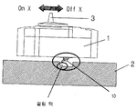
도 1a,1b는 종래의 일반적인 플러그-인 타입 배선용 차단기의 외부 베이스와의 조립 전후의 전체 외관을 나타낸 도면이다. 1A and 1B are views showing the overall appearance before and after assembly with an external base of a conventional plug-in type circuit breaker.
도시된 바와같이 배선용 차단기는 외함(1), 외함이 장착(설치)되는 외부 베이스(일명 플러그-인 베이스라고도 불림)(2), 배선용 차단기를 온 또는 오프위치로 수동조작하기 위한 핸들(3)로 구성되며, 종래의 경우에 배선용 차단기는 외부 베이스(2)에 배선용 차단기가 장착 또는 분리여부에 관계없이 핸들(3)에 의해 배선용 차단기의 온/오프 조작이 가능하였다.As shown, the wiring breaker is an enclosure (1), an outer base (also called a plug-in base) on which the enclosure is mounted (also called a plug-in base), and a handle (3) for manual operation of the wiring breaker in the on or off position. In the conventional case, the wiring breaker was able to operate the circuit breaker on / off by the
하지만, 이러한 종래의 배선용 차단기는 외부 베이스에 장착 또는 분리에 따라 배선용 차단기의 개폐기구의 동작을 구속할 수 있는 안전장치가 없으므로 인해 활선상태에서 플러그-인 타입의 배선용 차단기를 설치 또는 분리작업시에 배선용 차단기가 온 상태을 유지함으로 인해 작업자의 감전사고를 초래할 수 있는 안전상의 문제점이 있다. However, such a conventional circuit breaker does not have a safety device that can restrain the operation of the opening and closing mechanism of the circuit breaker according to the mounting or detachment of the external base, and thus, when installing or removing the plug-in type circuit breaker in the live state. There is a safety problem that may cause an electric shock accident of the operator because the circuit breaker is kept on.
본 발명은 상기한 문제점을 해결하기 위한 것으로서, 배선용 차단기가 외부 베이스(2)와 분리되어 있을 경우에는 개폐기구가 항상 트립상태를 유지하도록 개폐기구를 구속하고, 배선용 차단기가 외부 베이스(2)에 결합 장착되었을 경우에만 핸들(3)의 조작 및 온 동작이 가능하게 함으로써, 플러그-인 타입 배선용 차단기의 교체 및 설치작업 중 발생할 수 있는 감전사고로부터 작업자(사용자)를 보호할 수 있는 배선용 차단기를 제공하는 데 그 목적이 있다.The present invention is to solve the above problems, when the wiring breaker is separated from the outer base (2) restrains the opening and closing mechanism so that the opening and closing mechanism is always in a trip state, the wiring breaker to the outer base (2) By operating and turning on the handle (3) only when it is combined and mounted, it provides a wiring breaker to protect the operator (user) from electric shocks that may occur during the replacement and installation of the plug-in type circuit breaker. Its purpose is to.
상기 본 발명의 목적은 회로를 개폐하는 개폐기구와, 상기 개폐기구를 트립위치로 작동시키는 트립바를 구비하고, 외부 베이스상에 설치되는 배선용 차단기에 있어서,An object of the present invention is to provide a circuit breaker having an opening and closing mechanism for opening and closing a circuit, and a trip bar for operating the opening and closing mechanism in a trip position, and is provided on an outer base,
상기 개폐기구가 트립위치로 작동되도록, 상기 트립 바를 회동하게 가압하거나 상기 트립 바에의 가압을 해제하는 방향으로 이동가능한 트립 작동봉과;A trip operating rod movable in a direction to pressurize the trip bar or to release the pressurization to the trip bar so that the opening and closing mechanism is operated to a trip position;
상기 배선용 차단기의 저면에 고정되는 지지부재와, A support member fixed to the bottom of the circuit breaker;
상기 지지부재에 회전가능하게 지지되며, 상기 배선용 차단기가 상기 외부 베이스상에 설치되었을 때는 일방으로 회전하고 상기 배선용 차단기가 상기 외부 베이스로부터 이탈하였을 때는 타방으로 회전하면서 작용력을 제공하는 제 1 레버와,A first lever rotatably supported by the support member, the first breaker rotating to one side when the wiring breaker is installed on the outer base and the other lever to rotate to the other side when the wiring breaker is separated from the outer base;
상기 제 1 레버에 타방으로 회전하도록 탄성력을 제공하는 스프링과,A spring providing elastic force to the first lever to rotate in the other direction;
일단부가 상기 제 1 레버와 접속되고 타단부는 상기 트립 작동봉에 가압 가능하게 설치되어, 상기 제 1 레버가 일방으로 회전하였을 때 상기 트립 작동봉에의 가압을 해제하여 상기 트립 바가 해방되도록 하고, 상기 제 1 레버가 타방으로 회전하였을 때 상기 트립 작동봉을 가압하여 트립 바를 트립위치로 회동하게 가압하도록 하는 제 2 레버를 구비하는 안전기구 어셈블리를 포함하여 구성되는 것을 특징으로 하는 본 발명에 따른 배선용 차단기를 제공함으로써 달성될 수 있다.One end is connected to the first lever and the other end is pressurized to the trip actuating rod, so that the trip bar is released by releasing the pressure on the trip actuating rod when the first lever rotates in one direction. And a safety mechanism assembly having a second lever for pressing the trip operating rod to rotate the trip bar to the trip position when the first lever rotates in the other direction. By providing a breaker.
이하, 첨부도면을 참조하여 본 발명의 실시예에 대하여 설명하기로 한다.Hereinafter, embodiments of the present invention will be described with reference to the accompanying drawings.
도 2는 본 발명의 배선용 차단기가 외부 베이스에 결합 장착되기 전의 상태를 나타내는 사시도로서, 종래의 배선용 차단기의 외함(1)에 본 발명에 따른 안전기구 어셈블리(10)가 부가장치로서 부착되어 있고 외부 베이스(2)에는 이러한 안전기구 어셈블리(10)가 삽입 장착될수 있도록 수용홈(부호 미지정)이 형성되어 있다. Figure 2 is a perspective view showing a state before the circuit breaker of the present invention is coupled to the outer base, the
이러한 안전기구 어셈블리(10)는 도 8 및 도 9의 부분 확대사시도 및 분해 사시도에 도시된 바와 같이, 배선용 차단기의 저면에 고정되는 지지부재(7)와, Such a
지지부재(7)에 회전가능하게 지지되며, 상기 배선용 차단기가 외부 베이스(2)상에 설치되었을 때는 일방(실시예상 시계방향)으로 회전하고 상기 배선용 차단기가 외부 베이스(2)로부터 이탈하였을 때는 타방(실시예상 반시계방향)으로 회전 하면서 작용력을 제공하는 제 1 레버(9)와,It is rotatably supported by the supporting
제 1 레버(9)에 타방(실시예상 반시계방향)으로 회전하도록 탄성력을 제공하는 스프링(8)과,A
일단부가 제 1 레버(9)와 접속되고 타단부는 트립 작동봉(도 3, 4, 6, 7의 부호 4 참조)에 가압 가능하게 설치되어, 제 1 레버(9)가 일방(실시예상 시계방향)으로 회전하였을 때 상기 트립 작동봉(4)에의 가압을 해제하여 트립 바(도 3, 4, 6, 7의 부호 5 참조)가 해방되도록 하고, 제 1 레버(9)가 타방(실시예상 반시계방향)으로 회전하였을 때 상기 트립 작동봉(4)을 가압하여 트립 바(5)를 트립위치로 회동하게 가압하도록 하는 제 2 레버(6)로 구성된다. One end is connected to the
지지부재(7)는 양단부측에 배선용 차단기의 외함(1)의 저면에 지지부재(7)를 고정하기 위한 스크류 삽입홀(7b)이 2개 구비하고 길이방향상 중앙부분에는 제 2 레버(6)의 상하이동을 안내하기 위한 레버 안내홈(7d)이 마련된 고정판부(7a)와, 상기 제 1 레버(9)를 그 하부측벽상에 회전가능하게 지지하기 위한 핀으로 구성되는 회전축(7d)을 포함한다.The supporting
바람직하기로 스프링(8)은 비틀림 스프링(torsion spring)으로 구성하며, 그 일단부는 제 1 레버(9)의 상부면에 지지되고, 그 타단부는 지지부재(7)의 상기 하부측벽의 측면상에 지지되어, 제 1 레버(9)에 일방(반시계방향)으로 회동하도록 탄성력을 인가한다.Preferably the
제 1 레버(9)는 그 일단부에 외부 베이스에 접촉하여 제 1 레버(9)를 타방향(시계방향)으로 회동시키는 압력을 받기 위한 작용돌부(9a)를 구비하며, 길이방향 상 중앙부에 상기 회전축(7d)가 삽입되는 회전축공(9b)이 구비되고, 그 타단부에는 제 2 레버(6)이 접속된다. 제 1 레버(9)와 제 2 레버(6)의 접속은 제 1 레버(9)에 형성한 연결돌부와 제 2 레버(6)에 형성한 연결홈부를 결합하여 접속할 수도 있고, 별도의 핀을 양 레버의 연결부에 관통하여 접속하는 등 다양한 접속구성이 가능하다.The
한편, 도 3은 배선용 차단기의 핸들이 트립위치에 있을 때 본 발명에 따른 안전기구 어셈블리와 트립작동봉과 트립 바의 연동구성을 보여주기 위해서 배선용 차단기내부의 단극차단유니트에 이들이 조립된 상태를 나타낸 사시도이다. 도 3을 참조하여 안전기구 어셈블리와 트립작동봉과 트립 바의 연동구성을 설명하면 다음과 같다. On the other hand, Figure 3 is a perspective view showing a state in which they are assembled in the single-pole breaking unit inside the wiring breaker to show the interlocking configuration of the safety mechanism assembly, the trip operating rod and the trip bar when the handle of the wiring breaker is in the trip position. to be. Referring to Figure 3 describes the interlocking configuration of the safety mechanism assembly, trip operation rod and trip bar.
상기 안전기구 어셈블리(10)의 제 2 레버(6)의 상단부와 그 하단부가 접촉하게 트립 작동봉(4)가 설치된다. 트립 작동봉(4)는 실시예상 아크가스의 가스압을 이용해 트립구동력을 얻는 가스압 트립기구에 있어서 배출되는 아크가스압력에 의해 트립 바(5)를 트립방향으로 회동시키게 상방으로 이동하거나 아크가스압력이 없을 때는 자중에 의해 하방으로 원위치하는 작동봉이다. 실시예상 단극차단유니트(배선용 차단기의 내부의 상별 차단유니트로서 도 3의 핸들 아래부분 전체를 칭함, 그 내부는 가동접촉자와 고정접촉자등으로 구성되는 개폐기구와 소호부로 구성되고, 아크의 전이를 차단하기 위해 절연재로 밀폐되어 있고, 소호된 아크가스가 배출되는 구멍만이 측면과 전후면에 형성되어 있는 구성임)의 측면 아크가스 배출공에 그 하단부가 연접하고 단극차단유니트의 측면에 형성된 안내벽부에 의해 안내되 어 상하로 이동가능하게 설치된다. 트립 작동봉(4)의 상부에는 트립 바(5)가 트립 작동봉(4)과 접촉가능하게 위치한다. 본 발명에 따른 안전기구 어셈블리(10)의 제 2 레버(6)는 상기 가스압 트립기구의 작동에 관계없이 단지 배선용 차단기가 외부 베이스(2)로부터 분리되면 즉시 트립 작동봉(4)를 상방으로 밀어올리며, 그에 따라트립 작동봉(4)이 트립 바(5)를 가압 회동시키므로서 개폐기구를 트립시키게 된다.The
한편 도 2, 도 3 및 도 4를 참조하여 본원 발명의 배선용 차단기가 외부 베이스로부터 분리되었을 때 트립되는 동작을 설명하면 다음과 같다.On the other hand with reference to Figures 2, 3 and 4 will be described the operation tripped when the circuit breaker of the present invention is separated from the external base as follows.
배선용 차단기를 도 2에 도시된 바와 같이 외부 베이스(2)로부터 분리하면, 도 4에 도시된 바와 같이 스프링(8)의 탄성력 보다 큰 힘으로 제 1 레버(9)의 작용돌부(9a)에 작용하던 외부 베이스(2)에 의한 압력이 해방되면서, 수평방향으로 누어있는 자세(부호 ①상태)였던 제 1 레버(9)가 스프링(8)의 탄성력에 의해 시계반대방향으로 회동하여 비스듬하게 서 있는 자세(부호 ②상태)로 된다. 그러면 제 1 레버(9)의 단부에 접속된 제 2 레버(6)가 상방으로 상승하고(부호 ③상태), 따라서 제 2 레버(6)에 그 하단부가 접촉하고 있는 트립 작동봉(4)도 상승하는 제 2 레버(6)에 밀려서 상승한다(부호 ④상태). 트립 작동봉(4)이 상승하면서 그 선단부가 트립 바(5)를 밀어 회동시키면(부호 ⑤상태), 회동하는 트립 바(5)에 의해서 개폐기구가 트립위치로 동작하게 된다(부호 ⑥상태). 따라서 회로가 차단되어, 작업자는 감전의 위험으로부터 보호된다. 이때 배선용 차단기 내부의 단극 차단 유니트는 도3와 같이 핸들(3)이 트립위치에 있게 된다.When the circuit breaker is separated from the
한편 도 5, 도 6 및 도 7을 참조하여 본원 발명의 배선용 차단기가 외부 베 이스(2)에 장착되었 때 트립 바(5)가 해방되어 핸들(3)을 온위치 또는 오프위치로 자유로히 조작가능한 상태로 되는 동작을 설명하면 다음과 같다.Meanwhile, with reference to FIGS. 5, 6 and 7, when the circuit breaker of the present invention is mounted on the
도 5와 같이 배선용 차단기를 안전기구 어셈블리(10)가 외부 베이스(2)의 상기 수용 홈에 삽입되게 하여 외부 베이스(2)에 결합 장착한다. 그러면 도 7을 참조로 할 수 있는 바와 같이, 비스듬하게 서있는 자세였던 제 1 레버(9)는 그의 하단부 즉, 작용돌부(9a)가 외부 베이스 (2)의 상기 수용홈의 저면에 의해 가압되면서(부호 ①상태) 제 1 레버(9)는 스프링(8)의 탄성력에도 불구하고 도면상 시계방향으로 회동한다(부호 ②상태). 이때, 바람직한 실시예로서 상기 수용홈에 도2에 표기된 바와 같은 걸림턱을 형성하면, 이러한 턱이 없을 때 보다 제 1 레버(9)의 회동각도가 더욱 커질 수 있고, 따라서 제 2 레버(6)과 트립 작동봉(4)의 수직방향 변위량도 더욱 커질 수 있다. 그러면 제 1 레버(9)의 단부에 접속된 제 2 레버(6)가 하방으로 하강하고(부호 ③상태), 따라서 제 2 레버(6)에 그 하단부가 접촉하고 있는 트립 작동봉(4)도 하강하는 제 2 레버(6)을 따라서 자중에 의해 하강한다(부호 ④상태). 트립 작동봉(4)이 하강하면서 트립 바(5)를 가압하던 그 선단부가 트립 바(5)를 해방시켜 원위치 복귀시키며(부호 ⑤상태), 원위치하는 트립 바(5)에 의해서 개폐기구도 원위치 복귀될 수 있어 핸들(3)을 온위치 또는 오프위치로 자유로히 조작가능하게 된다(부호 ⑥상태). 이때 배선용 차단기 내부의 단극 차단 유니트는 도6와 같이 핸들(3)이 오프위치 또는 온위치로 조작하게 된다.As shown in FIG. 5, the circuit breaker is coupled to the
이상과 같은 본 발명의 바람직한 실시예는 예시의 목적으로 개시된 것이며, 당업자라면 본 발명에 제시된 사상의 범위안에서 다양한 수정,변경,부가가 가능할 것이며 이러한 것들은 본 발명의 청구범위에 속하는 것으로 보야 할 것이다.Preferred embodiments of the present invention as described above are disclosed for the purpose of illustration, and those skilled in the art will be able to make various modifications, changes, additions within the scope of the spirit set forth in the present invention and these should be seen as belonging to the claims of the present invention.
본 발명은 기존의 배선용 차단기 내부에 별도의 부속장치 없이 외부에 부가장치 구조의 안전기구 어셈블리를 간단하게 조립장착할 수 있고, 배선용 차단기가 외부 베이스로부터 분리되었을 때는 내부 트립장치를 구동하여 개폐기구를 자동트립시키고 배선용 차단기가 외부 베이스에 결합 장착되었을 경우에만 배선용 차단기온 조작 가능하게 함으로써 활선상태에서 배선용 차단기를 분리하거나 설치시에 발생할 수 있는 안전사고를 미연에 방지할 수가 있다.According to the present invention, a safety mechanism assembly having an additional device structure can be easily assembled and mounted without an additional accessory inside the existing circuit breaker. When the circuit breaker is separated from the external base, the opening and closing mechanism is driven by driving the internal trip device. The automatic tripping and the wiring breaker temperature can be operated only when the circuit breaker is connected to the external base and the wiring breaker temperature can be operated to prevent the safety accident that may occur when the wiring breaker is disconnected or installed in the live state.
Claims (2)
Priority Applications (1)
| Application Number | Priority Date | Filing Date | Title |
|---|---|---|---|
| KR1020040076875A KR100574895B1 (en) | 2004-09-24 | 2004-09-24 | Circuit breaker |
Applications Claiming Priority (1)
| Application Number | Priority Date | Filing Date | Title |
|---|---|---|---|
| KR1020040076875A KR100574895B1 (en) | 2004-09-24 | 2004-09-24 | Circuit breaker |
Publications (2)
| Publication Number | Publication Date |
|---|---|
| KR20060027950A KR20060027950A (en) | 2006-03-29 |
| KR100574895B1 true KR100574895B1 (en) | 2006-04-27 |
Family
ID=37138820
Family Applications (1)
| Application Number | Title | Priority Date | Filing Date |
|---|---|---|---|
| KR1020040076875A Expired - Fee Related KR100574895B1 (en) | 2004-09-24 | 2004-09-24 | Circuit breaker |
Country Status (1)
| Country | Link |
|---|---|
| KR (1) | KR100574895B1 (en) |
Cited By (2)
| Publication number | Priority date | Publication date | Assignee | Title |
|---|---|---|---|---|
| KR100876413B1 (en) | 2007-07-12 | 2008-12-31 | 엘에스산전 주식회사 | Breaker with overcurrent relay interlock trip |
| CN108281330A (en) * | 2017-01-05 | 2018-07-13 | Ls产电株式会社 | Magnetic trip gear for breaker |
Families Citing this family (3)
| Publication number | Priority date | Publication date | Assignee | Title |
|---|---|---|---|---|
| KR101412592B1 (en) * | 2010-09-03 | 2014-06-26 | 엘에스산전 주식회사 | Draw-out safety apparatus for circuit breaker |
| KR200486559Y1 (en) * | 2013-07-22 | 2018-06-07 | 엘에스산전 주식회사 | Mounting Structure of MOV assembly of Surge Protector |
| KR102299858B1 (en) * | 2017-03-15 | 2021-09-08 | 엘에스일렉트릭 (주) | Magnetic trip mechanism for circuit breaker |
-
2004
- 2004-09-24 KR KR1020040076875A patent/KR100574895B1/en not_active Expired - Fee Related
Cited By (3)
| Publication number | Priority date | Publication date | Assignee | Title |
|---|---|---|---|---|
| KR100876413B1 (en) | 2007-07-12 | 2008-12-31 | 엘에스산전 주식회사 | Breaker with overcurrent relay interlock trip |
| CN108281330A (en) * | 2017-01-05 | 2018-07-13 | Ls产电株式会社 | Magnetic trip gear for breaker |
| US10460897B2 (en) | 2017-01-05 | 2019-10-29 | Lsis Co., Ltd. | Magnetic trip device for circuit breaker |
Also Published As
| Publication number | Publication date |
|---|---|
| KR20060027950A (en) | 2006-03-29 |
Similar Documents
| Publication | Publication Date | Title |
|---|---|---|
| EP2492944B1 (en) | Circuit breaker | |
| JP4816246B2 (en) | Earth leakage breaker | |
| KR100574895B1 (en) | Circuit breaker | |
| JP4556614B2 (en) | Earth leakage breaker | |
| EP0354048B1 (en) | Circuit breaker trip bar interlock | |
| KR101158639B1 (en) | A switching mechanism for circuit braker | |
| KR100914204B1 (en) | Wiring breakers with contact-on appliances | |
| KR100845532B1 (en) | Trip device of earth leakage breaker | |
| KR100885849B1 (en) | Circuit breaker with contact on mechanism | |
| KR100574424B1 (en) | Circuit breaker | |
| KR200466294Y1 (en) | Current-limit structure of molded case circuit breaker | |
| KR102457966B1 (en) | Driving apparatus for load breaker switch | |
| KR200441578Y1 (en) | Alarm device for circuit breaker | |
| KR200382140Y1 (en) | The device for alarm switch of circuit breaker | |
| KR200224242Y1 (en) | device for tripping circuit in molded case circuit breaker | |
| KR200224237Y1 (en) | structure for operating trip button in molded case circuit breaker | |
| KR200196955Y1 (en) | Switchgear of wiring breaker | |
| KR200406795Y1 (en) | Circuit breaker | |
| KR200208219Y1 (en) | Switchgear of wiring breaker | |
| KR200148664Y1 (en) | Protectection device for vacuum circuit breaker pulling-out | |
| CN216389237U (en) | Switching-on and switching-off mechanism of plastic casing type circuit breaker | |
| KR100597973B1 (en) | Circuit breaker | |
| KR100319405B1 (en) | Spring loading device of operation mechanism for vacuum interrupter | |
| KR20030047206A (en) | trip reason indicator of circuit breaker | |
| KR100576694B1 (en) | Safety device for wiring breaker |
Legal Events
| Date | Code | Title | Description |
|---|---|---|---|
| A201 | Request for examination | ||
| PA0109 | Patent application |
St.27 status event code: A-0-1-A10-A12-nap-PA0109 |
|
| PA0201 | Request for examination |
St.27 status event code: A-1-2-D10-D11-exm-PA0201 |
|
| R18-X000 | Changes to party contact information recorded |
St.27 status event code: A-3-3-R10-R18-oth-X000 |
|
| PG1501 | Laying open of application |
St.27 status event code: A-1-1-Q10-Q12-nap-PG1501 |
|
| E701 | Decision to grant or registration of patent right | ||
| PE0701 | Decision of registration |
St.27 status event code: A-1-2-D10-D22-exm-PE0701 |
|
| GRNT | Written decision to grant | ||
| PR0701 | Registration of establishment |
St.27 status event code: A-2-4-F10-F11-exm-PR0701 |
|
| PR1002 | Payment of registration fee |
St.27 status event code: A-2-2-U10-U11-oth-PR1002 Fee payment year number: 1 |
|
| PG1601 | Publication of registration |
St.27 status event code: A-4-4-Q10-Q13-nap-PG1601 |
|
| R18-X000 | Changes to party contact information recorded |
St.27 status event code: A-5-5-R10-R18-oth-X000 |
|
| R18-X000 | Changes to party contact information recorded |
St.27 status event code: A-5-5-R10-R18-oth-X000 |
|
| R18-X000 | Changes to party contact information recorded |
St.27 status event code: A-5-5-R10-R18-oth-X000 |
|
| PR1001 | Payment of annual fee |
St.27 status event code: A-4-4-U10-U11-oth-PR1001 Fee payment year number: 4 |
|
| PR1001 | Payment of annual fee |
St.27 status event code: A-4-4-U10-U11-oth-PR1001 Fee payment year number: 5 |
|
| PN2301 | Change of applicant |
St.27 status event code: A-5-5-R10-R13-asn-PN2301 St.27 status event code: A-5-5-R10-R11-asn-PN2301 |
|
| PN2301 | Change of applicant |
St.27 status event code: A-5-5-R10-R13-asn-PN2301 St.27 status event code: A-5-5-R10-R11-asn-PN2301 |
|
| PR1001 | Payment of annual fee |
St.27 status event code: A-4-4-U10-U11-oth-PR1001 Fee payment year number: 6 |
|
| R18-X000 | Changes to party contact information recorded |
St.27 status event code: A-5-5-R10-R18-oth-X000 |
|
| FPAY | Annual fee payment |
Payment date: 20120327 Year of fee payment: 7 |
|
| PR1001 | Payment of annual fee |
St.27 status event code: A-4-4-U10-U11-oth-PR1001 Fee payment year number: 7 |
|
| PN2301 | Change of applicant |
St.27 status event code: A-5-5-R10-R13-asn-PN2301 St.27 status event code: A-5-5-R10-R11-asn-PN2301 |
|
| FPAY | Annual fee payment |
Payment date: 20130222 Year of fee payment: 8 |
|
| PR1001 | Payment of annual fee |
St.27 status event code: A-4-4-U10-U11-oth-PR1001 Fee payment year number: 8 |
|
| PR1001 | Payment of annual fee |
St.27 status event code: A-4-4-U10-U11-oth-PR1001 Fee payment year number: 9 |
|
| R18-X000 | Changes to party contact information recorded |
St.27 status event code: A-5-5-R10-R18-oth-X000 |
|
| PR1001 | Payment of annual fee |
St.27 status event code: A-4-4-U10-U11-oth-PR1001 Fee payment year number: 10 |
|
| FPAY | Annual fee payment |
Payment date: 20160401 Year of fee payment: 11 |
|
| PR1001 | Payment of annual fee |
St.27 status event code: A-4-4-U10-U11-oth-PR1001 Fee payment year number: 11 |
|
| P22-X000 | Classification modified |
St.27 status event code: A-4-4-P10-P22-nap-X000 |
|
| LAPS | Lapse due to unpaid annual fee | ||
| PC1903 | Unpaid annual fee |
St.27 status event code: A-4-4-U10-U13-oth-PC1903 Not in force date: 20170422 Payment event data comment text: Termination Category : DEFAULT_OF_REGISTRATION_FEE |
|
| PC1903 | Unpaid annual fee |
St.27 status event code: N-4-6-H10-H13-oth-PC1903 Ip right cessation event data comment text: Termination Category : DEFAULT_OF_REGISTRATION_FEE Not in force date: 20170422 |
|
| PN2301 | Change of applicant |
St.27 status event code: A-5-5-R10-R13-asn-PN2301 St.27 status event code: A-5-5-R10-R11-asn-PN2301 |
|
| PN2301 | Change of applicant |
St.27 status event code: A-5-5-R10-R13-asn-PN2301 St.27 status event code: A-5-5-R10-R11-asn-PN2301 |
|
| R18-X000 | Changes to party contact information recorded |
St.27 status event code: A-5-5-R10-R18-oth-X000 |