KR20100109400A - Solid state image pickup device, method of manufacturing the same, image pickup device, and electronic device - Google Patents
Solid state image pickup device, method of manufacturing the same, image pickup device, and electronic device Download PDFInfo
- Publication number
- KR20100109400A KR20100109400A KR1020100025580A KR20100025580A KR20100109400A KR 20100109400 A KR20100109400 A KR 20100109400A KR 1020100025580 A KR1020100025580 A KR 1020100025580A KR 20100025580 A KR20100025580 A KR 20100025580A KR 20100109400 A KR20100109400 A KR 20100109400A
- Authority
- KR
- South Korea
- Prior art keywords
- waveguide
- pixel
- incident
- imaging device
- solid
- Prior art date
- Legal status (The legal status is an assumption and is not a legal conclusion. Google has not performed a legal analysis and makes no representation as to the accuracy of the status listed.)
- Withdrawn
Links
- 238000004519 manufacturing process Methods 0.000 title claims description 52
- 239000007787 solid Substances 0.000 title description 2
- 238000003384 imaging method Methods 0.000 claims abstract description 306
- 238000006243 chemical reaction Methods 0.000 claims abstract description 147
- 230000003287 optical effect Effects 0.000 claims abstract description 48
- 239000000758 substrate Substances 0.000 claims abstract description 47
- 239000004065 semiconductor Substances 0.000 claims abstract description 41
- 230000001939 inductive effect Effects 0.000 claims abstract description 22
- 239000010410 layer Substances 0.000 claims description 192
- 238000012937 correction Methods 0.000 claims description 111
- 210000001747 pupil Anatomy 0.000 claims description 110
- 230000035945 sensitivity Effects 0.000 claims description 78
- 239000011229 interlayer Substances 0.000 claims description 46
- 239000000463 material Substances 0.000 claims description 44
- 238000000034 method Methods 0.000 claims description 35
- 230000001965 increasing effect Effects 0.000 claims description 19
- 238000012545 processing Methods 0.000 claims description 16
- 230000008569 process Effects 0.000 claims description 4
- 238000004611 spectroscopical analysis Methods 0.000 claims 2
- 238000012546 transfer Methods 0.000 description 52
- 230000000052 comparative effect Effects 0.000 description 34
- 238000010586 diagram Methods 0.000 description 31
- 238000009792 diffusion process Methods 0.000 description 29
- 229910021420 polycrystalline silicon Inorganic materials 0.000 description 19
- 229920005591 polysilicon Polymers 0.000 description 19
- 230000015572 biosynthetic process Effects 0.000 description 13
- 230000003321 amplification Effects 0.000 description 12
- 238000003199 nucleic acid amplification method Methods 0.000 description 12
- 230000006872 improvement Effects 0.000 description 11
- 229910052581 Si3N4 Inorganic materials 0.000 description 9
- 239000003086 colorant Substances 0.000 description 9
- HQVNEWCFYHHQES-UHFFFAOYSA-N silicon nitride Chemical compound N12[Si]34N5[Si]62N3[Si]51N64 HQVNEWCFYHHQES-UHFFFAOYSA-N 0.000 description 9
- 239000011347 resin Substances 0.000 description 8
- 229920005989 resin Polymers 0.000 description 8
- 230000004075 alteration Effects 0.000 description 7
- XUIMIQQOPSSXEZ-UHFFFAOYSA-N Silicon Chemical compound [Si] XUIMIQQOPSSXEZ-UHFFFAOYSA-N 0.000 description 6
- 230000007423 decrease Effects 0.000 description 6
- 150000004767 nitrides Chemical class 0.000 description 6
- 229910052710 silicon Inorganic materials 0.000 description 6
- 239000010703 silicon Substances 0.000 description 6
- 230000009467 reduction Effects 0.000 description 5
- NCGICGYLBXGBGN-UHFFFAOYSA-N 3-morpholin-4-yl-1-oxa-3-azonia-2-azanidacyclopent-3-en-5-imine;hydrochloride Chemical compound Cl.[N-]1OC(=N)C=[N+]1N1CCOCC1 NCGICGYLBXGBGN-UHFFFAOYSA-N 0.000 description 4
- VYPSYNLAJGMNEJ-UHFFFAOYSA-N Silicium dioxide Chemical compound O=[Si]=O VYPSYNLAJGMNEJ-UHFFFAOYSA-N 0.000 description 4
- 230000008901 benefit Effects 0.000 description 4
- 230000000694 effects Effects 0.000 description 4
- 230000006870 function Effects 0.000 description 4
- 230000002093 peripheral effect Effects 0.000 description 4
- 229910052814 silicon oxide Inorganic materials 0.000 description 4
- 238000002834 transmittance Methods 0.000 description 4
- 238000005229 chemical vapour deposition Methods 0.000 description 3
- 238000000576 coating method Methods 0.000 description 3
- 230000004907 flux Effects 0.000 description 3
- 238000002347 injection Methods 0.000 description 3
- 239000007924 injection Substances 0.000 description 3
- 238000002156 mixing Methods 0.000 description 3
- 238000001228 spectrum Methods 0.000 description 3
- 238000013459 approach Methods 0.000 description 2
- 230000004888 barrier function Effects 0.000 description 2
- 238000004364 calculation method Methods 0.000 description 2
- 238000011161 development Methods 0.000 description 2
- 229910003460 diamond Inorganic materials 0.000 description 2
- 239000010432 diamond Substances 0.000 description 2
- 238000009413 insulation Methods 0.000 description 2
- 239000012212 insulator Substances 0.000 description 2
- 239000002184 metal Substances 0.000 description 2
- 238000002161 passivation Methods 0.000 description 2
- 238000000059 patterning Methods 0.000 description 2
- 238000003860 storage Methods 0.000 description 2
- 229910004298 SiO 2 Inorganic materials 0.000 description 1
- 241000519995 Stachys sylvatica Species 0.000 description 1
- 230000000295 complement effect Effects 0.000 description 1
- 238000007796 conventional method Methods 0.000 description 1
- 230000003247 decreasing effect Effects 0.000 description 1
- 238000001514 detection method Methods 0.000 description 1
- 238000001312 dry etching Methods 0.000 description 1
- 238000005530 etching Methods 0.000 description 1
- 238000002474 experimental method Methods 0.000 description 1
- 238000001459 lithography Methods 0.000 description 1
- 229910044991 metal oxide Inorganic materials 0.000 description 1
- 150000004706 metal oxides Chemical class 0.000 description 1
- 229920003229 poly(methyl methacrylate) Polymers 0.000 description 1
- 239000004926 polymethyl methacrylate Substances 0.000 description 1
- 230000008054 signal transmission Effects 0.000 description 1
- HBMJWWWQQXIZIP-UHFFFAOYSA-N silicon carbide Chemical compound [Si+]#[C-] HBMJWWWQQXIZIP-UHFFFAOYSA-N 0.000 description 1
- 230000009466 transformation Effects 0.000 description 1
Images


Classifications
-
- H—ELECTRICITY
- H10—SEMICONDUCTOR DEVICES; ELECTRIC SOLID-STATE DEVICES NOT OTHERWISE PROVIDED FOR
- H10F—INORGANIC SEMICONDUCTOR DEVICES SENSITIVE TO INFRARED RADIATION, LIGHT, ELECTROMAGNETIC RADIATION OF SHORTER WAVELENGTH OR CORPUSCULAR RADIATION
- H10F39/00—Integrated devices, or assemblies of multiple devices, comprising at least one element covered by group H10F30/00, e.g. radiation detectors comprising photodiode arrays
- H10F39/80—Constructional details of image sensors
- H10F39/806—Optical elements or arrangements associated with the image sensors
-
- H—ELECTRICITY
- H10—SEMICONDUCTOR DEVICES; ELECTRIC SOLID-STATE DEVICES NOT OTHERWISE PROVIDED FOR
- H10F—INORGANIC SEMICONDUCTOR DEVICES SENSITIVE TO INFRARED RADIATION, LIGHT, ELECTROMAGNETIC RADIATION OF SHORTER WAVELENGTH OR CORPUSCULAR RADIATION
- H10F39/00—Integrated devices, or assemblies of multiple devices, comprising at least one element covered by group H10F30/00, e.g. radiation detectors comprising photodiode arrays
- H10F39/011—Manufacture or treatment of image sensors covered by group H10F39/12
- H10F39/024—Manufacture or treatment of image sensors covered by group H10F39/12 of coatings or optical elements
-
- H—ELECTRICITY
- H10—SEMICONDUCTOR DEVICES; ELECTRIC SOLID-STATE DEVICES NOT OTHERWISE PROVIDED FOR
- H10F—INORGANIC SEMICONDUCTOR DEVICES SENSITIVE TO INFRARED RADIATION, LIGHT, ELECTROMAGNETIC RADIATION OF SHORTER WAVELENGTH OR CORPUSCULAR RADIATION
- H10F39/00—Integrated devices, or assemblies of multiple devices, comprising at least one element covered by group H10F30/00, e.g. radiation detectors comprising photodiode arrays
- H10F39/80—Constructional details of image sensors
- H10F39/805—Coatings
- H10F39/8053—Colour filters
-
- H—ELECTRICITY
- H10—SEMICONDUCTOR DEVICES; ELECTRIC SOLID-STATE DEVICES NOT OTHERWISE PROVIDED FOR
- H10F—INORGANIC SEMICONDUCTOR DEVICES SENSITIVE TO INFRARED RADIATION, LIGHT, ELECTROMAGNETIC RADIATION OF SHORTER WAVELENGTH OR CORPUSCULAR RADIATION
- H10F39/00—Integrated devices, or assemblies of multiple devices, comprising at least one element covered by group H10F30/00, e.g. radiation detectors comprising photodiode arrays
- H10F39/80—Constructional details of image sensors
- H10F39/813—Electronic components shared by multiple pixels, e.g. one amplifier shared by two pixels
Landscapes
- Transforming Light Signals Into Electric Signals (AREA)
- Solid State Image Pick-Up Elements (AREA)
Abstract
본 발명의 고체 촬상 장치는 반도체 기판의 행방향 및 열방향으로 배치된 단위 화소에 의해 정의된 화소부를 포함하고, 상기 단위 화소 각각은, 반도체 기판상에 형성되고 입사광을 신호 전하로 변환하는 광전 변환부와, 상기 광전 변환부 상방에 형성되고 상기 광전 변환부에 상기 입사광을 유도하는 도파로와, 상기 도파로 상방에 형성되고 상기 도파로의 광 입사단에 상기 입사광을 유도하는 마이크로 렌즈를 포함하고, 상기 도파로는 광 입사단으로부터 사출단을 향해 단면적이 일정한 주상체를 포함하고, 상기 마이크로 렌즈로부터 상기 도파로의 광 입사단상에 입사되는 상기 입사광의 광속의 중심과, 상기 도파로의 중심축이 일치하도록 배치되는 것을 특징으로 한다.The solid-state imaging device of the present invention includes a pixel portion defined by unit pixels arranged in a row direction and a column direction of a semiconductor substrate, each of the unit pixels being formed on a semiconductor substrate and converting incident light into signal charges. And a waveguide formed above the photoelectric conversion unit and inducing the incident light to the photoelectric conversion unit, and a microlens formed above the waveguide and inducing the incident light to an optical incidence end of the waveguide. And a columnar body having a constant cross-sectional area from the light incident end to the exit end, wherein the center of the light beam of the incident light incident on the light incident end of the waveguide from the microlens is aligned with the center axis of the waveguide. It features.
Description
본 발명은 고체 촬상 장치와 그 제조 방법 및 촬상 장치 및 고체 촬상 장치를 구비한 카메라 등의 전자 기기에 관한 것이다. BACKGROUND OF THE INVENTION Field of the Invention The present invention relates to a solid-state imaging device, a manufacturing method thereof, and an electronic apparatus such as a camera having an imaging device and a solid-state imaging device.
고체 촬상 장치로서, CMOS(Complementary Metal Oxide Semiconductor) 등의 MOS형 이미지 센서로 대표되는 증폭형 고체 촬상 장치가 알려져 있다. 또한, CCD(Charge Coupled Device) 이미지 센서로 대표되는 전하 전송형 고체 촬상 장치가 알려져 있다. 이들 고체 촬상 장치는 디지털 카메라, 디지털 비디오 카메라 등에 폭넓게 사용되고 있다. MOS 고체 촬상 장치는 전원 전압이 낮고, 저소비 전력 때문에, 카메라가 장착된 휴대 전화나 PDA 등(Personal Digital Assistant)의 모바일 기기에 많이 사용되어 있다. As a solid-state imaging device, the amplification type solid-state imaging device represented by MOS type image sensors, such as a complementary metal oxide semiconductor (CMOS), is known. In addition, a charge transfer solid-state imaging device represented by a charge coupled device (CCD) image sensor is known. These solid-state imaging devices are widely used for digital cameras, digital video cameras, and the like. The MOS solid-state imaging device has a low power supply voltage and low power consumption, and thus is widely used in mobile devices such as mobile phones and PDAs (Personal Digital Assistants) equipped with cameras.
일반적인 MOS 고체 촬상 장치는 1개의 광전 변환부인 포토 다이오드와 복수의 화소 트랜지스터를 군(group)으로 하는 단위 화소를 복수로 배열하여 구성된다. 근래, 화소 사이즈의 미세화가 진행되어 단위 화소 당 화소 트랜지스터의 갯수를 줄이고 포토 다이오드 면적을 넓히기 위해, 화소 트랜지스터를 복수의 화소로 공유시킨 단위 화소군을 배열하는 화소 공유의 MOS 고체 촬상 장치가 개발되고 있다(일본국 특개2006-54276호 공보 및 일본국 특개2009-135319호 공보 참조).A general MOS solid-state imaging device is constructed by arranging a plurality of unit pixels including a photodiode as one photoelectric conversion unit and a plurality of pixel transistors as a group. In recent years, in order to miniaturize the pixel size and to reduce the number of pixel transistors per unit pixel and to enlarge the photodiode area, a pixel-sharing MOS solid-state imaging device in which a unit pixel group in which pixel transistors are shared by a plurality of pixels is arranged, has been developed. (See Japanese Patent Application Laid-Open No. 2006-54276 and Japanese Patent Application Laid-Open No. 2009-135319).
또한, 고체 촬상 장치로서, 입사광을 각각 대응하는 포토 다이오드에 유도하기 위한 도파로를 배치하여 감도 특성을 향상하도록 한 고체 촬상 장치도 알려져 있다(일본국 특개2008-166677호 공보 참조). 또한, 고체 촬상 장치로서, 셰이딩을 보정하기 위해, 온 칩 렌즈에 대한 퓨필 보정(pupil correction)을 행하는 고체 촬상 장치도 알려져 있다(일본국 특허 제2600250호 참조).Moreover, as a solid-state imaging device, the solid-state imaging device which arrange | positions the waveguide for inducing incident light to the corresponding photodiode, respectively, and improves a sensitivity characteristic is also known (refer Unexamined-Japanese-Patent No. 2008-166677). In addition, as a solid-state imaging device, a solid-state imaging device that performs a pupil correction on an on-chip lens to correct shading is also known (see Japanese Patent No. 2600250).
고체 촬상 장치는 입사광을 광전 변환하는 포토 다이오드 상방에 도파로가 형성되고, 상기 도파로에 입사광을 유도하기 위한 온 칩 렌즈가 마련되어 있다. 또한, 온 칩 렌즈와 도파로의 사이에 컬러 필터층이 형성되어 있고, 상기 컬러 필터층에 의해 입사광을 예를 들면 RGB의 각각의 색(적색광, 녹색광, 청색광)으로 분광하고 있다. 그리고, 색수차의 영향을 줄이기 위해 RGB 각각의 색에 대응한 온 칩 렌즈의 곡률을 조정하고 있다. 또한, 온 칩 렌즈와 컬러 필터의 고화상(high image) 고위치(height position)에서의 퓨필 보정량을 렌즈 CRA(Chief Ray angle : 주광선 입사 각도) 보다 적게 설정하고, 색수차의 영향을 줄이고 있다. In the solid-state imaging device, a waveguide is formed above a photodiode for photoelectric conversion of incident light, and an on-chip lens for inducing incident light in the waveguide is provided. In addition, a color filter layer is formed between the on-chip lens and the waveguide, and the color filter layer spectra incident light into respective colors (red light, green light, blue light) of, for example, RGB. In order to reduce the influence of chromatic aberration, the curvature of the on-chip lens corresponding to each RGB color is adjusted. In addition, the pupil correction amount at the high image high position of the on-chip lens and the color filter is set smaller than the lens CRA (Chief Ray angle), and the influence of chromatic aberration is reduced.
예를 들면, 주광선 입사각도가 높은(예를 들면, 25도) 온 칩 렌즈를 사용한 경우에, 고화상 고위치에서의 색수차에 의해 셰이딩(결상 위치(깊이)의 차이) 또는 혼색이 발생한다. For example, when an on-chip lens having a high chief ray incident angle (for example, 25 degrees) is used, shading (difference in image position (depth)) or mixed color occurs due to chromatic aberration at a high image high position.
또한, 종래 기술과 같이 색마다 온 칩 렌즈의 곡률을 조정하는 방법이 사용되는 경우, 온 칩 렌즈의 제작 공정수가 많아진다. 또한, 화소가 미세화됨에 따라 온 칩 렌즈의 곡률이 높게 되기 때문에, 색마다의 조정은 곤란하게 된다. Moreover, when the method of adjusting the curvature of an on-chip lens for every color like a conventional technique is used, the number of manufacturing processes of an on-chip lens becomes large. In addition, since the curvature of the on-chip lens becomes high as the pixels are miniaturized, adjustment for each color becomes difficult.
고입사 각도부에서는 포토 다이오드(Photo Diode)의 중심으로 보다도 광학 중심 방향(예를 들면, 화소부의 중심 방향)으로 결상 중심이 치우치기(F광 포함) 때문에, 셰이딩이나 혼색이 발생한다. 이 때문에, 종래 기술의 경우, 예를 들면 색마다 온 칩 렌즈의 곡률을 조정하지 않는 경우, 색수차에 의해 도파로의 입사 단면에서의 입사광의 스폿 지름이 색마다 다르기 때문에, 화소가 미세화됨에 따라 모든 색에 대해 균형이 잡혔던 위치로 하는 보정을 행하는 것이 곤란해진다. 또한, 온 칩 렌즈나 컬러 필터를 색마다 퓨필 보정량을 다른 양으로 한다면 간극이나 중복 부분이 발생하고, 셰이딩이나 혼색이 발생하게 된다.에서는 경사광에 대해서도 효과적으로 집광할 수 있도록, 온 칩 렌즈나 컬러 필터에는 퓨필 보정이 추가되어 있다. 그러나, 그러한 구조에 있어서도, 화각 주변에서 감도가 떨어지는 휘도 셰이딩이나, 색깔마다 셰이딩 형상이 다른 것에 기인한 색 셰이딩이 큰 문제가 되어 있다. In the high-incidence angle portion, shading and mixed color occur because the imaging center is shifted (including F light) from the optical center direction (for example, the center direction of the pixel portion) rather than from the center of the photodiode. Therefore, in the case of the prior art, for example, when the curvature of the on-chip lens is not adjusted for each color, the spot diameter of the incident light at the incident end surface of the waveguide is different for each color due to chromatic aberration, so that all the colors as the pixels are miniaturized. It becomes difficult to correct the position to a balanced position with respect to. If the on-chip lens or the color filter has different pupil correction amounts for each color, gaps or overlapping portions occur, and shading or mixing occurs. In the on-chip lens or color, the condensed light can be effectively collected. A filter correction is added to the filter. However, in such a structure as well, color shading due to a lack of sensitivity shading around the field of view or different shading shapes for each color is a major problem.
입사광의 입사각이 큰 경우에도 광전 변환부에 입사광을 유도하는 도파로로서, 화각을 4상한으로 나누어, 위치에 따라 도파로의 테이퍼 위치를 바꾸고, 다른 입사각도의 입사광을 도파로에 유도하는 기술이 개시되어 있다(예를 들면, 일본국 특개2005-175234호 공보 참조). As a waveguide for inducing incident light even in a large incident angle of the incident light, a technique of dividing an angle of view into four upper limits, changing the taper position of the waveguide according to the position, and inducing incident light of different incident angles into the waveguide is disclosed. (See, for example, Japanese Patent Laid-Open No. 2005-175234).
그렇지만, 도파로의 일부를 테이퍼 형상으로 형성하더라도. 상기 도파로에 수직으로 입사한 광이 테이퍼 형상의 도파로내의 경사면에 의해 반사되기 때문에 감도가 저하된다는 것을 본 발명자들은 발견하였다. 이 때문에, 도파로의 예를 들어 일부라도 테이퍼 형상으로 형성하는 것은 감도의 저하를 초래하기 때문에 바람직하지 않다. 또한, 도파로의 일부에 테이퍼 형상을 형성하는 것은 통상의 도파로를 형성하는 것 보다도 공정수 및 마스크의 수의 증가를 초래한다. 또한, 상기 기술은 화각을 4상한으로 나누어 도파로의 형상을 바꾸기만 하는 것이어서, 셰이딩 특성의 개선으로 연결되는 기술은 아니다. However, even if part of the waveguide is formed into a tapered shape. The inventors found that the sensitivity is lowered because the light incident perpendicularly to the waveguide is reflected by the inclined plane in the tapered waveguide. For this reason, it is not preferable to form even a part of the waveguide in a tapered shape, for example, because it causes a decrease in sensitivity. In addition, forming a tapered shape in a part of the waveguide causes an increase in the number of processes and masks than in forming a normal waveguide. In addition, the technique merely changes the shape of the waveguide by dividing the angle of view into four upper limits, and thus is not a technique that leads to an improvement in shading characteristics.
도 1에, 종래의 2화소 공유의 MOS 고체 촬상 장치(1)의 예를 나타낸다. 고체 촬상 장치(1)는 2개의 포토 다이오드(PD1, PD2)와, 2개의 전송 트랜지스터(Tr11, Tr12)와, 1개의 플로팅 디퓨전부(FD), 리셋 트랜지스터(Tr2), 증폭 트랜지스터(Tr3)에 의해, 2화소 공유의 단위 화소군(2)이 구성된다. 상기 예에서는 베이어 패턴(Bayer pattern)의 컬러 필터가 사용되고 있기 때문에, 청색 화소(B)의 옆에 제1 녹색 화소(Gb)이 배열되고, 적색 화소(R)의 옆에 제2녹색 화소(Gr)이 배열되도록, 2화소 공유의 단위 화소군(2)이 배열된다. 도 1에서는 적색 화소(R)와 제1의 녹색 화소(Gb)에 의한 2화소 공유의 단위 화소군(2), 및 청색 화소(B)과 제2의 녹색 화소(Gr)에 의한 2화소 공유의 단위 화소군(2)이 반복 배열된다. 1 shows an example of a conventional two pixel shared MOS solid-
전송 트랜지스터(Tr11, Tr12)는 각각 폴리실리콘에 의한 전송 게이트 전극(3)과, 포토 다이오드(PD)(PD1, PD2)와, 플로팅 디퓨전부(FD)를 갖고 구성된다. 리셋 트랜지스터(Tr2)는 폴리실리콘에 의한 리셋 게이트 전극(4)와, 플로팅 디퓨전부(FD)와, 소스 영역(5)을 갖고 구성된다. 증폭 트랜지스터(Tr3)는 폴리실리콘에 의한 증폭 게이트 전극(6)과, 소스 영역(7) 및 드레인 영역(8)을 갖고 구성된다. 플로팅 디퓨전부(FD)와 증폭 게이트 전극(6)은 배선(9)에 의해 접속된다. 증폭 트랜지스터(Tr3)의 소스 영역은 수직 신호선(도시 생략)이 접속된다. The transfer transistors Tr11 and Tr12 each have a
상기 고체 촬상 장치(1)에서는 제1의 녹색 화소(Gb)의 전송 게이트 전극(3)과, 제2의 녹색 화소(Gr)의 전송 게이트 전극(3)의 레이아웃이 비대칭이기 때문에, 상기 레이아웃에 영향을 주어, 제1 및 제2의 녹색 화소(Gb 및 Gr)의 감도에 차이가 생긴다. 예를 들면, 전송 게이트 전극(3)에 의한 하지의 레이아웃의 차이로, 경사 입사한 광의 일부가 한편의 녹색 화소의 전송 게이트 전극에 의해 가려지거나 하여, 양쪽 녹색 화소(Gb, Gr)의 입사 광량에 차이가 생긴다. MOS 고체 촬상 장치에서는 화소 사이즈의 미세화와 더불어 양 화소 사이의 감도차가 현저해지기 때문에, 상기 감도차가 미세화의 장애가 되어 있다. In the solid-
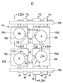
한편, 도 2에 도시하는 바와 같이 2화소 공유의 단위 화소군(2)을 지그재그 배열한 고체 촬상 장치(11)가 제안되어 있다. 상기 고체 촬상 장치(11)에서는 2화소 공유의 단위 화소군(2)이 지그재그 배열된 것으로, 제1 및 제2의 녹색 화소(Gb 및 Gr)의 전송 게이트 전극의 레이아웃이 대칭이 되고, 녹색 화소(Gb 및 Gr) 사이의 감도차의 개선을 도모하고 있다. On the other hand, as shown in FIG. 2, the solid-
제1 및 제2의 녹색 화소(Gb 및 Gr)의 감도차는 격자 노이즈 등의 노이즈의 원인도 되고, 색 셰이딩의 원인도 되기 때문에, 감도차가 없는 것이 바람직하다. Since the sensitivity difference between the first and second green pixels Gb and Gr may cause noise such as lattice noise and color shading, it is preferable that there is no sensitivity difference.
그런데, 도 2에 도시된 고체 촬상 장치(11)에서, 제1 및 제2의 녹색 화소(Gb 및 Gr)의 전송 게이트 전극의 레이아웃을 대칭으로 유지하기 때문에, 화소 트랜지스터의 레이아웃가 플로팅 디퓨전부(FD)의 레이아웃은 제약을 받는다. 상기 제약은 미세화의 장애가 된다. 예를 들면, 상기 단위 화소군(2)는 2화소 공유만을 할 수 있고, 따라서, 4화소 공유의 레이아웃과 비교하여 2배의 화소 트랜지스터나 플로팅 디퓨전부가 필요하게 되어, 광전 변환을 위한 포토 다이오드(PD)의 면적이 줄어들게 된다. 포토 다이오드(PD)의 면적 감소는 감도 손실의 원인이 된다. 또한, 고체 촬상 장치(11)에서는 녹색 화소(Gb, Gr)의 전송 게이트 전극(3)의 레이아웃에 대해, 적색 화소(R), 청색 화소(B)의 전송 게이트 전극(3)의 레이아웃이 비대칭이 되기 때문에, 색 셰이딩 발생을 방지하는 것이 용이하지 않다. By the way, in the solid-
상술한 것처럼, 인접하는 화소 사이의 경계에 대해 비대칭 배열을 갖는 하지층에 기인하여, 화소들 사이에서 광학적 비대칭성이 생긴다. As described above, due to the underlying layer having an asymmetrical arrangement with respect to the boundary between adjacent pixels, optical asymmetry occurs between the pixels.
본 발명은 상술한 문제점을 감안하여, 전극, 배선 등을 포함하는 하지층의 비대칭성에 기인하는 화소에 대한 광학적 비대칭성을 개선하도록 한 고체 촬상 장치, 및 상기 고체 촬상 장치를 구비한 카메라 등의 전자 기기를 제공한 것이다. SUMMARY OF THE INVENTION In view of the above-described problems, the present invention provides a solid-state imaging device designed to improve optical asymmetry for pixels caused by asymmetry of an underlayer including electrodes, wirings, and the like, and an electronic device such as a camera equipped with the solid-state imaging device. The device was provided.
본 발명에 관한 고체 촬상 장치는 화소가 배열된 화소부와, 복수 화소의 군내에서 상기 복수 화소의 군의 광입사면 보다 하방에 형성되고 전극 및 배선을 포함하는 레이아웃가 소요의 인접하는 화소의 경계선을 사이에 두고 비대칭의 하지층을 갖는다. 또한, 본 발명은 하지층에 기인하여 생기는 각 화소 사이의 광학적 비대칭성을 광학적 대칭성으로 하기 위한 조정 수단을 갖는다. The solid-state imaging device according to the present invention includes a pixel portion in which pixels are arranged and a boundary line between adjacent pixels, which are formed below the light incidence plane of the group of the plurality of pixels within the group of the plurality of pixels and whose layout including electrodes and wiring is required. It has an asymmetric base layer in between. In addition, the present invention has adjustment means for making optical asymmetry between the optical asymmetry between the pixels resulting from the underlying layer.
본 발명의 고체 촬상 장치의 바람직한 형태는 화소부가 복수의 화소를 1개의 소요의 화소 트랜지스터로 공유하는 단위 화소군이 복수 배열된 화소부로 하고, 비대칭의 하지층이 화소 트랜지스터의 게이트 전극 및 배선을 포함하는 하지층으로 한다. A preferred embodiment of the solid-state imaging device of the present invention is a pixel portion in which a plurality of unit pixel groups in which a pixel portion shares a plurality of pixels with one required pixel transistor are arranged in a pixel portion, and an asymmetric base layer includes a gate electrode and wiring of the pixel transistor. It is said that it is base layer.
본 발명의 고체 촬상 장치에서는 조정 수단의 위치 이탈의 조정 방향 및 조정량에 의해, 입사광에 대한 하지층의 영향이 줄어들거나 또는 없어져서, 각 화소의 광전 변환부에의 입사광의 입사 효율이 균일화된다. In the solid-state imaging device of the present invention, the influence of the underlying layer on the incident light is reduced or eliminated by the adjustment direction and the adjustment amount of the positional deviation of the adjustment means, so that the incident efficiency of the incident light on the photoelectric conversion section of each pixel is made uniform.
본 발명의 화소의 바람직한 형태에서는 화소부가 이른바 화소 공유의 단위 화소군의 배열로 형성되기 때문에, 단위 화소군 내, 혹은 인접하는 복수의 단위 화소군 내에서의, 적어도 동색 화소의 광전 변환부에 대한 입사광의 입사 효율이 균일화된다. In a preferred embodiment of the pixel of the present invention, since the pixel portions are formed in an arrangement of so-called pixel-sharing unit pixel groups, at least the same color pixels in the photoelectric conversion portion in the unit pixel group or in a plurality of adjacent unit pixel groups. Incident efficiency of incident light becomes uniform.
본 발명에 관한 전자 기기는 고체 촬상 장치와, 고체 촬상 장치의 광전 변환부에 입사광을 유도하는 광학계와, 고체 촬상 장치의 출력 신호를 처리하는 신호 처리 회로를 구비한다. 고체 촬상 장치는 상기 본 발명에 의한 고체 촬상 장치로 구성된다. An electronic apparatus according to the present invention includes a solid-state imaging device, an optical system for inducing incident light in the photoelectric conversion section of the solid-state imaging device, and a signal processing circuit for processing the output signal of the solid-state imaging device. The solid-state imaging device is constituted by the solid-state imaging device according to the present invention.
본 발명의 전자 기기에서는 본 발명의 고체 촬상 장치가 사용됨에 의해, 입사광에 대한 하지층의 영향이 줄어들거나 혹은 없어져서, 각 화소의 광전 변환부에의 입사광의 입사 효율이 균일화된다. In the electronic device of the present invention, the use of the solid-state imaging device of the present invention reduces or eliminates the influence of the underlying layer on the incident light, so that the incident efficiency of the incident light into the photoelectric conversion section of each pixel is made uniform.
또한, 해결하려고 하는 문제점은 색수차에 의해 도파로의 입사 단면에서의 입사광의 스폿 지름이 색마다 다르기 때문에, 화소가 미세화됨에 따라 모든 색에 대해 균형 잡힌 위치로 하는 보정하는 것이 곤란하다는 점이고, 온 칩 렌즈나 컬러 필터를 색마다 퓨필 보정량을 다른 양으로 하면 간극이나 중복 부분이 발생하고, 셰이딩이나 혼색이 발생하는 점이다. In addition, the problem to be solved is that since the spot diameter of the incident light at the incident cross section of the waveguide is different for each color due to chromatic aberration, it is difficult to correct it to a balanced position for all colors as the pixels are miniaturized, and the on-chip lens If the color filter has a different amount of pupil correction for each color, gaps or overlapping portions occur, and shading or color mixing occurs.
본 발명은 온 칩 렌즈나 컬러 필터는 컬러 필터층을 투과한 입사광의 색마다 퓨필 보정을 행하지 않고, 입사광의 기준의 색으로의 퓨필 보정을 행하고, 색수차에 의해 입사광의 스폿 지름이 색마다 다르더라도, 입사광을 도파로의 입사 단면에 효율적으로 입사하는 것을 가능하게 한다. According to the present invention, the on-chip lens and the color filter do not correct the pupil for each color of the incident light that has passed through the color filter layer, and correct the pupil to the reference color of the incident light, even if the spot diameter of the incident light differs for each color due to chromatic aberration. It is possible to efficiently enter the incident light into the incident cross section of the waveguide.
본 발명의 고체 촬상 장치는 반도체 기판의 행방향 및 열방향으로 배치된 단위 화소에 의해 정의된 화소부를 포함하고, 상기 단위 화소 각각은 반도체 기판상에 형성되고 입사광을 신호 전하로 변환하는 광전 변환부와, 상기 광전 변환부 상방에 형성되고 상기 광전 변환부에 상기 입사광을 유도하는 도파로와, 상기 도파로 상방에 형성되고 상기 도파로의 광 입사단에 상기 입사광을 유도하는 마이크로 렌즈를 포함하고, 상기 도파로는 광 입사단으로부터 사출단을 향해 단면적이 일정한 주상체를 포함하고, 상기 마이크로 렌즈로부터 상기 도파로의 광 입사단상에 입사되는 상기 입사광의 광속의 중심과, 상기 도파로의 중심축이 일치하도록 배치되어 있다.The solid-state imaging device of the present invention includes a pixel portion defined by unit pixels arranged in a row direction and a column direction of a semiconductor substrate, each unit pixel being formed on a semiconductor substrate and converting incident light into signal charges. And a waveguide formed above the photoelectric conversion unit and inducing the incident light to the photoelectric conversion unit, and a micro lens formed above the waveguide and inducing the incident light to an optical incidence end of the waveguide. And a columnar body having a constant cross-sectional area from the light incident end to the exit end, and arranged so that the center of the light beam of the incident light incident on the light incident end of the waveguide from the microlens coincides with the center axis of the waveguide.
본 발명의 고체 촬상 장치에서는 도파로에서는 그 입사단으로부터 사출단을 향해 단면적이 일정의 주상체로 형성되어 있는 것으로, 도파로의 입사 단면에 수직으로 입사한 광은 도파로 측면을 반사하지 않고 도파로를 투과하기 때문에, 감도의 저하가 억제된다. 또한, 도파로의 입사 단면에 입사된 입사광의 광속의 중심과, 도파로의 중심축이 일치하여 배치되어 있어서,도파로에 대해 퓨필 보정이 이루어지고 있다. 따라서 마이크로 렌즈로부터 사출 된 입사광이 효율적으로 도파로내에 유도된다. In the solid-state imaging device of the present invention, the waveguide has a columnar body having a constant cross-sectional area from the incidence end to the exit end, and light incident perpendicularly to the incidence end surface of the waveguide passes through the waveguide without reflecting the waveguide side surface. The fall of the sensitivity is suppressed. Further, the center of the light beam of the incident light incident on the incident cross section of the waveguide coincides with the center axis of the waveguide, and pupil correction is performed on the waveguide. Therefore, the incident light emitted from the micro lens is efficiently guided in the waveguide.
본 발명의 고체 촬상 장치의 제조 방법은 입사광을 신호 전하로 변환하는 광전 변환부가 형성된 반도체 기판상에 복수층의 배선을 갖는 층간 절연막으로 된 배선층에 상기 광전 변환부상에 입사광을 유도하는 도파로 홀을 형성한 공정과, 상기 도파로 홀의 내부에 상기 층간 절연막 보다도 굴절율이 높은 도파로 재료막을 매입하고 상기 도파로 홀의 내부에 도파로를 형성한 공정과, 상기 도파로 재료막상에 평탄화 절연막을 이용하여 상기 입사광을 분광하는 컬러 필터층을 형성한 공정과, 상기 컬러 필터층상에 상기 입사광을 상기 광전 변환부에 유도하는 마이크로 렌즈를 형성한 공정을 갖고, 상기 광전 변환부를 갖는 단위 화소가 상기 반도체 기판의 행방향 및 열방향으로 복수씩 배치되고 화소부가 구성되고 있고, 상기 광전 변환부에 대응하여 형성되어 있는 상기 도파로에서는 입사단으로부터 사출단을 향해 단면적이 일정한 주상체로 형성되고, 상기 도파로의 입사 단면에 입사되는 상기 입사광의 광속의 중심과, 상기 도파로의 중심축이 일치하여 배치되어 있다. The manufacturing method of the solid-state imaging device of the present invention forms a waveguide hole for inducing incident light on the photoelectric conversion portion in a wiring layer of an interlayer insulating film having a plurality of layers of wirings on a semiconductor substrate on which a photoelectric conversion portion for converting incident light into signal charges is formed. And a step of embedding a waveguide material film having a higher refractive index than the interlayer insulating film inside the waveguide hole and forming a waveguide inside the waveguide hole; and a color filter layer for spectrosing the incident light using a planarization insulating film on the waveguide material film. And a step of forming a microlens for inducing the incident light on the photoelectric conversion part on the color filter layer, wherein a plurality of unit pixels having the photoelectric conversion part are provided in a row direction and a column direction of the semiconductor substrate. Disposed and configured with a pixel portion, and corresponding to the photoelectric conversion portion In is the waveguide being formed as a cross-sectional area towards the exit end from the incident end constant circumference, it is arranged to the central axis of the waveguide in the center of the incident light beam, and is incident on the entrance end face of the waveguide matching.
본 발명의 고체 촬상 장치의 제조 방법에서는 도파로에서는 그 입사단으로부터 사출단을 향해 단면적이 일정한 주상체로 형성된 것으로, 도파로의 입사 단면에 수직으로 입사한 광은 도파로 측면에서 반사하지 않고 도파로를 투과하기 때문에, 감도의 저하가 억제된다. 또한, 도파로의 입사 단면에 입사된 입사광의 광속의 중심과, 도파로의 중심축이 일치하여 배치되는 것으로, 도파로에 대해 퓨필 보정이 이루어진다. 따라서 마이크로 렌즈로부터 사출된 입사광이 효율적으로 도파로내에 유도된다. In the manufacturing method of the solid-state imaging device of the present invention, the waveguide is formed as a columnar body having a constant cross-sectional area from the incidence end to the exit end. The fall of the sensitivity is suppressed. Further, the pupil correction is performed for the waveguide by arranging the center of the light beam of the incident light incident on the incident cross section of the waveguide and the center axis of the waveguide. Therefore, the incident light emitted from the micro lens is efficiently guided in the waveguide.
본 발명의 촬상 장치는 입사광을 집광한 집광 광학부와, 상기 집광 광학부로 집광한 광을 수광하고 광전 변환한 고체 촬상 장치를 갖는 촬상부와, 상기 고체 촬상 장치로 광전 변환된 신호를 처리하는 신호 처리부를 갖고, 상기 고체 촬상 장치는 반도체 기판에 형성되고 입사광을 신호 전하로 변환하는 광전 변환부와, 상기 광전 변환부 상방에 형성되어 있고 상기 광 전 변환부에 상기 입사광을 유도하는 도파로와, 상기 도파로 상방에 형성되어 있고 상기 도파로의 광 입사단에 상기 입사광을 유도하는 마이크로 렌즈를 갖는 단위 화소가 상기 반도체 기판의 행방향 및 열방향으로 복수씩 배치되어 화소부가 구성되고 있고, 상기 도파로에서는 입사단을 향해 단면적이 일정한 주상체로 형성되어 있고, 상기 마이크로 렌즈로부터 상기 도파로의 입사 단면에 입사되는 상기 입사광의 광속의 중심과, 상기 도파로의 중심축이 일치하여 배치되어 있다. An imaging device according to the present invention includes an imaging section having a condensing optical section condensing incident light, a solid-state imaging device which receives and photoelectrically converts the light condensed by the condensing optical section, and a signal for processing the photoelectric conversion signal by the solid-state imaging device. A solid-state imaging device having a processing portion, the photoelectric conversion portion being formed on a semiconductor substrate and converting incident light into signal charges, a waveguide formed above the photoelectric conversion portion and inducing the incident light to the photoelectric conversion portion; The pixel unit is formed by forming a plurality of unit pixels each having a microlens formed above the waveguide and inducing the incident light at the light incident end of the waveguide in the row direction and the column direction of the semiconductor substrate. The incidence cross section of the waveguide from the microlens, The center of the luminous flux of the incident light incident on and the center axis of the waveguide are arranged to coincide.
본 발명의 촬상 장치에서는 본 발명의 고체 촬상 장치가 사용된 것으로, 감도의 저하가 억제되고, 마이크로 렌즈로부터 사출된 입사광이 효율적으로 도파로내에 유도된다. In the imaging device of the present invention, the solid-state imaging device of the present invention is used, whereby a decrease in sensitivity is suppressed, and incident light emitted from the microlens is guided efficiently into the waveguide.
본 발명의 고체 촬상 장치는 도파로에 퓨필 보정을 행하고 있기 때문에, 입사광의 각각의 색이 각각 빠짐없이 도파로에 집광되게 되고, 셰이딩의 파장 의존에 의한 색 셰이딩을 개선할 수 있다는 이점이 있다. 또한, 셰이딩을 개선할 수 있기 때문에, 감도를 화면 전체로의 출력 평균치로 정의하면, 감도를 높이는 것을 할 수 있고, 예를 들면 노광 시간을 절감하는 것, 암부로의 촬상을 할 수 있는 것 등이 가능하게 된다. Since the solid-state imaging device of the present invention performs pupil correction on the waveguide, each color of the incident light is condensed on the waveguide without omission, and there is an advantage that color shading due to wavelength dependence of shading can be improved. In addition, since shading can be improved, if sensitivity is defined as an average value of output to the entire screen, the sensitivity can be increased, for example, to reduce the exposure time, to perform imaging with a dark part, and the like. This becomes possible.
본 발명의 고체 촬상 장치의 제조 방법에서는 도파로에 퓨필 보정을 행하기 때문에, 입사광의 각각의 색이 각각 빠짐없이 도파로에 집광되게 되고, 셰이딩의 파장 의존에 의한 색불균일(색 셰이딩)을 개선할 수 있다는 이점이 있다. 또한, 셰이딩을 개선할 수 있기 때문에, 감도를 화면 전체로의 출력 평균치로 정의하면, 감도를 높인 것을 할 수 있고, 예를 들면 노광 시간을 절감하는 것, 암부로의 촬상을 할 수 있다는 것 등이 가능해진다. 따라서, 공정수를 늘리지 않고, 색수차의 영향을 경감할 수 있다. 또한, 미세 화소에 있어, 도파로에 들어가지 않았던 광은 색마다 퓨필 보정량을 조정한 것으로 감소하고, 셰이딩이나 혼색을 절감할 수 있다. In the manufacturing method of the solid-state imaging device of the present invention, pupil correction is performed on the waveguide, so that each color of the incident light is condensed on the waveguide without missing, and color unevenness (color shading) due to wavelength dependence of shading can be improved. There is an advantage that it is. In addition, since shading can be improved, if sensitivity is defined as an average value of output to the entire screen, sensitivity can be increased, for example, to reduce the exposure time, to perform imaging with a dark part, and the like. This becomes possible. Thus, the influence of chromatic aberration can be reduced without increasing the number of steps. In addition, in the fine pixels, light that does not enter the waveguide is reduced by adjusting the pupil correction amount for each color, and shading and mixing color can be reduced.
본 발명의 촬상 장치는 본 발명의 고체 촬상 장치가 사용된 것으로, 셰이딩의 파장 의존에 의한 색불균일(색 셰이딩)을 개선할 수 있다, 감도를 높인 것을 할 수 있기 때문에, 고품질의 화상을 얻을 수 있다는 이점이 있다. In the imaging device of the present invention, the solid-state imaging device of the present invention is used, and color unevenness (color shading) due to wavelength dependence of shading can be improved, and since sensitivity can be increased, high quality images can be obtained. There is an advantage that it is.
본 발명에 관한 고체 촬상 장치에 의하면, 각 광전 변환부에의 입사광의 입사 효율이 균일화하기 때문에, 각 화소의 광전 변환부에 있어, 광학적 대칭성을 얻을 수 있다. 예를 들면 화소 공유의 고체 촬상 장치이라면, 비대칭의 하지층의 영향이 감소하고, 또는 없어지기 때문에, 같은 색 화소의 감도차가 개선된다. 또한, 색 셰이딩도 개선할 수 있다. According to the solid-state imaging device according to the present invention, since the incidence efficiency of incident light into each photoelectric conversion section is uniform, optical symmetry can be obtained in the photoelectric conversion section of each pixel. For example, in the case of a pixel shared solid-state imaging device, since the influence of the asymmetric underlayer is reduced or eliminated, the sensitivity difference between the same color pixels is improved. Color shading can also be improved.
본 발명에 관한 전자 기기에 의하면, 고체 촬상 장치에 있어서 각 화소의 광전 변환부에 있어, 광학적 대칭성을 얻을 수 있기 때문에, 전자 기기의 고화질화, 고품질화를 도모할 수 있다. According to the electronic device according to the present invention, since the optical symmetry can be obtained in the photoelectric conversion unit of each pixel in the solid-state imaging device, the image quality of the electronic device and the quality of the electronic device can be improved.
도 1은 종래의 2화소 공유의 고체 촬상 장치의 하나의 예를 나타내는 주요 부분의 개략 구성도.
도 2는 종래의 2화소 공유의 고체 촬상 장치의 다른 예를 나타내는 주요 부분의 개략 구성도.
도 3은 본 발명의 제1 실시의 형태에 관한 고체 촬상 장치의 구성의 제1의 예를 나타낸 개략 구성 단면도 및 평면 레이아웃도.
도 4는 본 발명의 퓨필 보정량의 산출 방법의 하나의 예를 나타낸 개략 구성 단면도.
도 5는 종래의 고체 촬상 장치의 구성예를 나타낸 개략 구성 단면도.
도 6은 종래예의 퓨필 보정량의 산출 방법의 하나의 예를 나타낸 개략 구성 단면도.
도 7은 색마다의 도파로의 퓨필 보정을 나타낸 개략 구성 단면도.
도 8은 본 발명의 고체 촬상 장치의 구성의 제2의 예를 나타낸 평면 레이아웃도.
도 9는 본 발명의 고체 촬상 장치의 구성의 제2의 예를 나타낸 개략 구성 단면도.
도 10은 본 발명의 고체 촬상 장치의 구성의 제3의 예를 나타낸 개략 구성 단면도.
도 11은 본 발명의 고체 촬상 장치의 구성의 제3의 예를 나타낸 개략 구성 단면도.
도 12는 본 발명의 고체 촬상 장치의 제조 방법의 제1의 예를 나타낸 제조 공정 단면도.
도 13은 고체 촬상 장치의 제조 방법의 제1의 예를 나타낸 제조 공정 단면도.
도 14는 고체 촬상 장치의 제조 방법의 제1의 예를 나타낸 제조 공정 단면도.
도 15는 고체 촬상 장치의 제조 방법의 제1의 예를 나타낸 제조 공정 단면도.
도 16은 고체 촬상 장치의 제조 방법의 제1의 예를 나타낸 제조 공정 단면도.
도 17은 고체 촬상 장치의 제조 방법의 제1의 예를 나타낸 제조 공정 단면도.
도 18은 고체 촬상 장치의 제조 방법의 제1의 예를 나타낸 제조 공정 단면도이다.
도 19는 고체 촬상 장치의 제조 방법의 제1의 예를 나타낸 제조 공정 단면도.
도 20은 고체 촬상 장치의 제조 방법의 제1의 예를 나타낸 제조 공정 단면도.
도 21은 고체 촬상 장치의 제조 방법의 제1의 예를 나타낸 제조 공정 단면도.
도 22는 본 발명의 고체 촬상 장치의 제조 방법의 제2의 예를 나타낸 제조 공정 단면도.
도 23은 고체 촬상 장치의 제조 방법의 제2의 예를 나타낸 제조 공정 단면도.
도 24는 고체 촬상 장치의 제조 방법의 제2의 예를 나타낸 제조 공정 단면도.
도 25는 고체 촬상 장치의 제조 방법의 제2의 예를 나타낸 제조 공정 단면도.
도 26은 고체 촬상 장치의 제조 방법의 제2의 예를 나타낸 제조 공정 단면도.
도 27은 고체 촬상 장치의 제조 방법의 제2의 예를 나타낸 제조 공정 단면도.
도 28은 고체 촬상 장치의 제조 방법의 제2의 예를 나타낸 제조 공정 단면도.
도 29는 본 발명의 제3 실시의 형태의 촬상 장치의 하나의 예를 나타낸 블록도.
도 30은 본 발명의 제 4 실시의 형태에 관한 고체 촬상 장치의 화소부를 나타내는 개략 구성부.
도 31은 본 발명의 제 4 실시의 형태에 관한 고체 촬상 장치의 주요 부분의 개략 구성도.
도 32는 도 31의 A-A 선상의 개략 단면도.
도 33은 도 31의 제 4 실시의 형태의 녹색 화소(Gb, Gr)의 파장대 출력의 그래프.
도 34는 본 발명의 제 5 실시의 형태에 관한 고체 촬상 장치의 주요 부분의 개략 구성도.
도 35는 본 발명의 제 6 실시의 형태에 관한 고체 촬상 장치의 최종적인 주요 부분의 개략 구성도.
도 36은 제 6 실시의 형태의 도파로의 이동의 설명에 제공하는 고체 촬상 장치의 주요 부분의 구성도.
도 37은 본 발명의 제 7 실시의 형태에 관한 고체 촬상 장치의 주요 부분의 개략 구성도.
도 38은 제 7 실시의 형태의 설명에 제공한 비교예의 고체 촬상 장치의 주요 부분의 개략 구성도.
도 39는 본 발명의 제 8 실시의 형태에 관한 고체 촬상 장치의 주요 부분의 개략 구성도.
도 40은 제 8 실시의 형태의 도파로 퓨필 보정의 설명에 제공한 고체 촬상 장치의 주요 부분의 단면도.
도 41의 A 및 B는 제 8 실시의 형태의 도파로 퓨필 보정의 설명에 제공한 고체 촬상 장치의 주요 부분의 단면도.
도 42의 A 및 B는 제 8 실시의 형태의 도파로 퓨필 보정의 설명에 제공한 고체 촬상 장치의 주요 부분의 평면도.
도 43은 제 8 실시의 형태의 도파로 퓨필 보정의 설명에 제공한 고체 촬상 장치의 화소부의 평면도.
도 44는 본 발명의 제 9 실시의 형태에 관한 고체 촬상 장치의 주요 부분의 개략 구성도.
도 45는 제 9 실시의 형태의 설명에 제공한 비교예의 고체 촬상 장치의 주요 부분의 개략 구성도.
도 46은 본 발명의 제10 실시의 형태에 관한 고체 촬상 장치의 주요 부분의 개략 구성도.
도 47은 도 46의 A-A 선상 및 B-B 선상의 개략 단면도.
도 48은 제10 실시의 형태의 설명에 제공한 비교예의 고체 촬상 장치의 주요 부분의 개략 구성도.
도 49는 도 48의 A-A 선상 및 B-B 선상의 개략 단면도.
도 50은 본 발명의 제11 실시의 형태에 관한 고체 촬상 장치의 주요 부분의 개략 구성도.
도 51은 도 50의 A-A 선상 및 B-B 선상의 개략 단면도.
도 52는 제11 실시의 형태의 설명에 제공한 비교예의 고체 촬상 장치의 주요 부분의 개략 구성도.
도 53은 도 52의 A-A 선상 및 B-B 선상의 개략 단면도.
도 54는 본 발명의 제12 실시의 형태에 관한 고체 촬상 장치의 주요 부분의 개략 구성도.
도 55의 A 및 B는 도 54의 A-A 선상의 개략 단면도, B-B 선상의 개략 단면도.
도 56은 제12 실시의 형태에 대한 비교예의 고체 촬상 장치의 주요 부분의 개략 구성도.
도 57의 A 및 B는 도 56의 A-A 선상의 개략 단면도, B-B 선상의 개략 단면도.
도 58은 본 발명의 제13 실시의 형태에 관한 고체 촬상 장치의 주요 부분의 개략 구성도.
도 59의 A 및 B는 도 58의 A-A 선상의 개략 단면도, B-B 선상의 개략 단면도.
도 60은 제13 실시의 형태에 대한 비교예의 고체 촬상 장치의 주요 부분의 개략 구성도.
도 61의 A 및 B는 도 60의 A-A 선상의 개략 단면도, B-B 선상의 개략 단면도.
도 62는 비교예에 관한 고체 촬상 장치의 주요 부분의 개략 구성도.
도 63은 도 62의 A-A 선상의 단면도.
도 64는 도 62의 비교예의 녹색 화소(Gb, Gr)의 파장대 출력의 그래프.
도 65는 비교예에 관한 고체 촬상 장치의 주요 부분의 개략 구성도이다.
도 66은 본 발명의 제14 실시의 형태에 관한 전자 기기의 개략 구성도. BRIEF DESCRIPTION OF THE DRAWINGS The schematic block diagram of the principal part which shows one example of the conventional two pixel shared solid-state imaging device.
Fig. 2 is a schematic configuration diagram of a main part showing another example of a conventional two pixel shared solid-state imaging device.
3 is a schematic sectional view and a planar layout diagram showing a first example of the configuration of a solid-state imaging device according to the first embodiment of the present invention.
4 is a schematic sectional view showing one example of a method for calculating a pupil correction amount of the present invention.
5 is a schematic sectional view showing a configuration example of a conventional solid-state imaging device.
6 is a schematic sectional view showing one example of a method for calculating a pupil correction amount of a conventional example.
Fig. 7 is a schematic sectional view showing pupil correction of waveguides for respective colors.
8 is a planar layout diagram showing a second example of the configuration of the solid-state imaging device of the present invention.
9 is a schematic sectional view showing a second example of the configuration of the solid-state imaging device of the present invention.
10 is a schematic sectional view illustrating a third example of the configuration of the solid-state imaging device of the present invention.
11 is a schematic sectional view showing a third example of the configuration of the solid-state imaging device of the present invention.
12 is a cross sectional view of the production process showing the first example of the method of manufacturing the solid-state imaging device of the present invention.
13 is a cross sectional view of the production process showing the first example of the method of manufacturing the solid-state imaging device.
14 is a cross sectional view of the production process showing the first example of the method of manufacturing the solid-state imaging device.
15 is a cross sectional view of the production process showing the first example of the method of manufacturing the solid-state imaging device.
16 is a cross sectional view of the production process showing the first example of the method of manufacturing the solid-state imaging device.
17 is a cross sectional view of the production process showing the first example of the method of manufacturing the solid-state imaging device.
18 is a cross sectional view of the production process showing the first example of the method of manufacturing the solid-state imaging device.
19 is a cross sectional view of the production process showing the first example of the method of manufacturing the solid-state imaging device.
20 is a cross sectional view of the production process showing the first example of the method of manufacturing the solid-state imaging device.
21 is a cross sectional view of the production process showing the first example of the method of manufacturing the solid-state imaging device.
Fig. 22 is a cross sectional view of the production process showing the second example of the method of manufacturing the solid-state imaging device of the present invention.
23 is a cross sectional view of the production process showing the second example of the method of manufacturing the solid-state imaging device.
24 is a cross sectional view of the production process showing the second example of the method of manufacturing the solid-state imaging device.
25 is a cross sectional view of the production process showing the second example of the method of manufacturing the solid-state imaging device.
26 is a cross sectional view of the production process showing the second example of the method of manufacturing the solid-state imaging device.
27 is a cross sectional view of the production process showing the second example of the method of manufacturing the solid-state imaging device.
Fig. 28 is a cross sectional view of the production process showing the second example of the method of manufacturing the solid-state imaging device.
29 is a block diagram showing an example of an imaging device according to a third embodiment of the present invention.
30 is a schematic constitutional part showing a pixel portion of a solid-state imaging device according to a fourth embodiment of the present invention.
31 is a schematic configuration diagram of a main part of a solid-state imaging device according to a fourth embodiment of the present invention.
32 is a schematic cross-sectional view taken along the line AA of FIG. 31.
33 is a graph of the wavelength band output of the green pixels Gb and Gr of the fourth embodiment of FIG.
34 is a schematic configuration diagram of a main part of the solid-state imaging device according to the fifth embodiment of the present invention.
35 is a schematic configuration diagram of a final main part of a solid-state imaging device according to the sixth embodiment of the present invention.
36 is a configuration diagram of a main part of the solid-state imaging device for explaining the movement of the waveguide according to the sixth embodiment.
37 is a schematic configuration diagram of a main part of a solid-state imaging device according to the seventh embodiment of the present invention.
38 is a schematic configuration diagram of a main part of a solid-state imaging device of a comparative example provided in the description of the seventh embodiment.
Fig. 39 is a schematic configuration diagram of a main part of the solid-state imaging device according to the eighth embodiment of the present invention.
40 is a cross-sectional view of principal parts of the solid-state imaging device provided for explaining the waveguide pupil correction according to the eighth embodiment.
41A and 41 are cross-sectional views of principal parts of the solid-state imaging device provided for explaining the waveguide pupil correction according to the eighth embodiment.
42A and 42 are plan views of main parts of the solid-state imaging device provided in the explanation of the waveguide pupil correction according to the eighth embodiment.
Fig. 43 is a plan view of a pixel portion of the solid-state imaging device provided for explaining the waveguide pupil correction according to the eighth embodiment.
44 is a schematic configuration diagram of a main part of a solid-state imaging device according to a ninth embodiment of the present invention.
45 is a schematic configuration diagram of a main part of a solid-state imaging device of a comparative example provided in the description of the ninth embodiment.
46 is a schematic configuration diagram of a main part of a solid-state imaging device according to a tenth embodiment of the present invention.
FIG. 47 is a schematic sectional view taken along the line A-A and line B-B in FIG. 46;
48 is a schematic configuration diagram of a main part of a solid-state imaging device of a comparative example provided in the description of the tenth embodiment.
FIG. 49 is a schematic sectional view taken along the line A-A and line B-B in FIG. 48;
50 is a schematic configuration diagram of a main part of a solid-state imaging device according to an eleventh embodiment of the present invention.
FIG. 51 is a schematic sectional view taken along the line A-A and line B-B in FIG. 50;
52 is a schematic configuration diagram of a main part of a solid-state imaging device of a comparative example provided in the description of the eleventh embodiment.
FIG. 53 is a schematic sectional view taken along the line A-A and line B-B in FIG. 52;
54 is a schematic configuration diagram of a main part of a solid-state imaging device according to a twelfth embodiment of the present invention.
55: A and B are schematic sectional views on the AA line of FIG. 54, and schematic sectional drawing on the B-B line.
56 is a schematic configuration diagram of a main part of a solid-state imaging device of a comparative example of the twelfth embodiment.
FIG. 57: A and B are schematic sectional views on the AA line of FIG. 56, and schematic sectional views on the B-B line.
58 is a schematic configuration diagram of a main part of a solid-state imaging device according to a thirteenth embodiment of the present invention.
59A and 59 are schematic sectional views taken along the line A-A in FIG. 58, and schematic sectional views taken along the line B-B.
60 is a schematic configuration diagram of a main part of a solid-state imaging device of a comparative example according to a thirteenth embodiment.
61 A and B are schematic sectional views on the AA line of FIG. 60, and schematic sectional views on the B-B line.
62 is a schematic configuration diagram of a main part of a solid-state imaging device according to a comparative example.
FIG. 63 is a sectional view taken along the line AA in FIG. 62;
64 is a graph of wavelength band output of green pixels Gb and Gr of the comparative example of FIG. 62;
65 is a schematic configuration diagram of a main part of the solid-state imaging device according to the comparative example.
66 is a schematic configuration diagram of an electronic device according to a fourteenth embodiment of the present invention.
이하, 본 발명을 실시하기 위한 형태(이하, 실시의 형태라고 한다)에 관하여 설명한다. EMBODIMENT OF THE INVENTION Hereinafter, the form (henceforth an embodiment) for implementing this invention is demonstrated.
1.제1의 실시의 형태1.First embodiment
고체 촬상 장치의 구성의 제1의 예First example of the configuration of the solid-state imaging device
본 발명의 제1 실시의 형태에 관한 고체 촬상 장치의 구성의 제1의 예를 도 3의 개략 구성 단면도 및 평면 레이아웃도에 의해 설명한다. 도 3의 A는 화각 중심의 단위 화소이고, 도 3의 B는 화각단의 단위 화소이고, 도 3의 C는 복수의 단위 화소로 된 화소부를 나타내고 있다. A first example of the configuration of the solid-state imaging device according to the first embodiment of the present invention will be described with a schematic configuration sectional view and a planar layout diagram of FIG. 3. A of FIG. 3 is a unit pixel of an angle of view, B of FIG. 3 is a unit pixel of an angle of view, and C of FIG. 3 represents a pixel portion including a plurality of unit pixels.
이하, 1은 고체 촬상 장치, 11은 반도체 기판, 12는 광전 변환부, 14는 층간 절연막, 16은 도파로, 17은 컬러 필터층, 18은 마이크로 렌즈, 19는 도파로 홀, 20은 화소부, 21은 단위 화소, 53은 도파로 재료막, 200은 촬상 장치, 201은 촬상부, 202는 집광 광학부, 203은 신호 처리부, 210(1)은 고체 촬상 장치를 나타내고 있다. 1 is a solid-state imaging device, 11 is a semiconductor substrate, 12 is a photoelectric converter, 14 is an interlayer insulating film, 16 is a waveguide, 17 is a color filter layer, 18 is a microlens, 19 is a waveguide hole, 20 is a pixel portion, and 21 is The unit pixel, 53 is a waveguide material film, 200 is an imaging device, 201 is an imaging unit, 202 is a condensing optical unit, 203 is a signal processing unit, and 210 (1) is a solid-state imaging device.
도 3에 도시하는 바와 같이 반도체 기판(11)의 표면측(입사광이 입사되는 측)에는 입사광을 신호 전하로 변환하는 광전 변환부(12)가 형성되어 있다. 상기 반도체 기판(11)에는 예를 들면 실리콘 기판이 사용되어 있다. 또는 SOI(Silicon on insulator) 기판이라도 좋다. 상기 경우, SOI 기판의 실리콘층에 상기 광전 변환부(12)가 형성된다. 상기 광전 변환부(12)의 상방에는 배선층(13)이 형성되어 있다. 상기 배선층(13)은 예를 들면 층간 절연막(14) 내에 복수층의 배선(15)이 형성된 것이다. 그리고, 상기 광전 변환부(12)의 상방에는 상기 배선(15)이 형성되지 않도록 한다. 또한, 상기 층간 절연막(14)의 표면은 평탄화되어 있다. As shown in FIG. 3, the
또한, 상기 배선층(13)의 상기 광전 변환부(12)의 상방 부분에는 상기 입사광을 상기 광전 변환부(12)에 유도하는 도파로(16)가 형성되어 있다. 상기 도파로(16)는 상기 광전 변환부(12) 상의 층간 절연막(14)에 도파로 홀을 형성하고, 그 도파로 홀에 상기 층간 절연막(14) 보다도 굴절율이 높은 투광성을 갖는 재료, 예를 들면 질화 실리콘막, 다이아몬드막 혹은 수지 재료를 매입하여 형성한 것이다. In addition, a
상기 도파로(16) 상방의 상기 층간 절연막(14) 위에는 상기 입사광을 분광하는 컬러 필터층(17)을 이용하여 상기 컬러 필터층(17)으로부터 사출된 입사광을 상기 도파로(16)의 광 입사단에 유도하는 마이크로 렌즈(18)가 형성되어 있다. 상기 마이크로 렌즈(18) 및 상기 컬러 필터층(17)에는 경사광에 대해서도 효과적으로 집광할 수 있도록, 퓨필 보정이 추가된다. 그 퓨필 보정량은 상기 화각 중심(예를 들면, 화소부 중심)으로부터 화각단을 향함에 따라 커지고 있다. 상기 컬러 필터층(17)은 예를 들면 입사광을 적색광, 녹색광, 청색광으로 분광하는 것으로, 각각의 색의 컬러 필터가 마련되어 있다. 또한, 상기 마이크로 렌즈(18)는 온 칩 렌즈(on-chip lens)라고 불리는 것으로, 볼록 렌즈 형상을 하고, 최상층에 마련되어 있다. On the
상기 광전 변환부(12), 도파로(16), 컬러 필터층(17), 마이크로 렌즈(18), 전송 게이트(도시 생략) 등의 구성을 단위 화소(21)로서, 상기 단위 화소(21)가 상기 반도체 기판(11)의 행방향 및 열방향으로 복수씩 배치되어 화소부(20)가 구성된다. 또한, 1 단위 화소, 2 단위 화소 혹은 4 단위 화소에 1개의 화소 증폭부(화소 트랜지스터부라고도 함)(도시 생략)가 갖춰져 있다. 상기 화소 증폭부는 전송 게이트에 의해 판독된 신호 전하를 증폭하고 출력한다. The
상기 화소부(20) 내의 각 광전 변환부(12)에 대응하여 형성되어 있는 상기 도파로(16)는 입사단으로부터 사출단을 향해 단면적이 일정한 주상체로 형성되어 있다. 예를 들면, 원주(cylinder), 달걀꼴 원주(oval cylinder)(타원주(elliptic cylinder)도 포함) 등이다. 또한, 상기 도파로(16)는 모서리부가 둥글게 형성된 각주라도 좋다. 그리고 상기 도파로(16) 입사 단면에 입사되는 상기 입사광의 광속의 중심(LC)과, 상기 도파로(16)의 중심축(C)이 일치하여 배치되어 있다. The
이 경우, 화각 중심의 단위 화소(21)(도 3의 A 참조. )에서는 중심축 방향으로 마이크로 렌즈(18)상에 입사광이 입사되기 때문에, 마이크로 렌즈(18)에 의해 집광된 입사광은 컬러 필터층(17)을 투과하여 분광되고, 도파로(16)의 광입사측 단면상에 입사된다. 그리고, 도파로(16)의 중심축(C)에 따라 유도되어 도파로(16)의 광사출측 단면으로부터 사출되고, 광전 변환부(12)의 중심상에 조사된다. 즉, 마이크로 렌즈(18)의 중심을 투과한 입사광은 컬러 필터층(17)의 중심, 도파로(16)의 중심축(C)에 따라 투과되고, 광전 변환부(12)의 중심상에 조사된다. 따라서 도파로(16)의 퓨필 보정은 행하지 않는다. In this case, since incident light is incident on the
화각 중심으로부터 벗어나는 단위 화소(21)(도 3의 B 참조. )에서는 상기한 것처럼, 상기 마이크로 렌즈(18) 및 상기 컬러 필터층(17)에는 경사광에 대해서도 효과적으로 집광할 수 있도록 퓨필 보정이 추가된다. 그와 함께, 상기 도파로(16)는 그 광입사측 단면상에 입사되는 상기 입사광의 광속의 중심(LC)과, 그 중심축(C)이 일치하도록 배치되어 있다. 즉, 도파로(16)에 대해 퓨필 보정을 행하고 있다. As described above, in the unit pixel 21 (see B of FIG. 3) deviating from the center of view, the pupil correction is added to the
또한, 상기 화소부(20) 안에서 동일한 파장의 입사광이 입사되는 상기 광전 변환부(12)에서는 상기 광전 변환부(12)의 중심에 대한 상기 도파로(16)의 중심축(C)의 어긋남 양은 상기 화소부(20)의 중심의 광전 변환부(12) 보다 외측 방향을 향해 커지고 있다. 즉, 화소부(20)의 중심으로부터 외측 방향으로 멀어짐에 따라, 마이크로 렌즈(18)에 의해 집광된 입사광의 입사각이 커지게 된다. 그 때, 마이크로 렌즈(18)에 대해서 퓨필 보정을 행하고 있지만, 그것으로는 불충분하다.에서는 입사광의 동일 파장의 광에 대해, 광전 변환부(12)의 중심에 대한 도파로(16)의 중심축의 어긋남 양이 크게 되는 것으로, 마이크로 렌즈(18)로부터 입사되는 광속의 중심이 도파로(16)의 중심축(C)에 일치하게 된다. In addition, in the
또한, 상기 도파로(16)는 그 지름이 도파로(16)의 사출단으로부터 사출되는 상기 입사광이 상기 광전 변환부(12)의 표면 내에 조사된 크기로 형성되고 있다. 따라서 종래 기술의 도파로와 같이 광전 변환부(12)의 표면의 크기와 동일한 크기로는 형성되지 않는다. 또한, 상기 도파로(16)의 지름은 상기 컬러 필터층(17)을 투과해 온 입사광의 상기 도파로(16)의 입사 단면에 있어서 스폿 지름 보다도 크게 형성되어 있는 것이 좋다. 또한, 스폿 지름은 입사광의 파장에 따라 다르고, 예를 들면 상기 컬러 필터층(17)에 의해 분광되는 색이 적색광, 녹색광, 청색광의 경우, 적색광의 스폿 지름이 가장 크고, 다음에 녹색광, 청색광의 순서가 된다. 따라서, 상기 도파로(16)의 지름은 각각의 색으로 바꾸어 형성하기 때문에, 레이아웃이 복잡하게 되고, 경우에 따라서는 배선층(13)의 배선(15)에 도파로(16)가 도달할 수도 있기 때문에, 예를 들면, 입사광의 중간의 파장 단계인 녹색광을 기준으로 결정된다. 또는 배선층(13)의 배선(15)과의 마진이 있는 경우에는 적색광을 기준으로 결정되어도 좋다. In addition, the
상기 설명한 바와 같이 상기 도파로(16)의 지름을 종래의 도파로 보다도 작게 함에 의해 퓨필 보정의 마진을 확대할 수 있다. 그와 함께, 도파로(16)의 주위에 배치되어 있는 배선(15)의 폭을 축소함에 의해, 또한 도파로(16)의 퓨필 보정량의 마진을 확대할 수 있다. 예를 들면, 상기 배선(15)의 선폭은 선폭의 축소에 의한 배선(15)의 저항층에 의해 클록 지연이 일어나지 않는 범위에서, 또한 프로세스상 가능한 한 축소할 수 있다. 예를 들면, 배선(15)의 선폭을 10nm 축소한 것으로 퓨필 보정량의 마진을 10nm 확대하는 것이 가능해진다. As described above, the diameter of the
상기와 같이 고체 촬상 장치(1)(1A)는 구성된다. As described above, the solid-state imaging device 1 (1A) is configured.
퓨필 보정량의 산출예Calculation example of pupil correction amount
다음에, 상기 고체 촬상 장치(1)의 퓨필 보정량의 산출 방법의 하나의 예를 도 4의 개략 구성 단면도에 의해, 이하에 설명한다. 도 4의 A는 화각 중심의 단위 화소이고, 도 4의 B는 화각단의 단위 화소를 나타내고 있다. Next, one example of the method for calculating the pupil correction amount of the solid-
도 4의 A에 도시된 바와 같이 화각 중심의 단위 화소(21)에서는 중심축 방향으로 마이크로 렌즈(18)상에 입사광이 입사되기 때문에, 마이크로 렌즈(18)에 의해 집광된 입사광은 컬러 필터층(17)을 투과하여 분광되고, 도파로(16)의 광입사측 단면상에 입사된다. 그리고, 도파로(16)의 중심축(C)에 따라 유도되고 도파로(16)의 광사출측 단면으로부터 사출되고, 광전 변환부(12)의 중심상에 조사된다. 즉, 마이크로 렌즈(18)의 중심을 투과한 입사광은 컬러 필터층(17)의 중심, 도파로(16)의 중심축(C)에 따라 투과되고, 광전 변환부(12)의 중심상에 조사된다. 따라서 도파로(16)의 퓨필 보정은 행하여 지지 않는다. As shown in FIG. 4A, since incident light is incident on the
한편, 화각단의 단위 화소(21)에서는 도 4의 B에 도시된 바와 같이 하나의 예로서, 마이크로 렌즈(18)에 입사한 입사광의 입사각(θ1)이 예를 들면 θ1=25°의 위치의 퓨필 보정량의 산출을 행한다. On the other hand, in the
마이크로 렌즈(18)의 굴절율(n)은 n=1.5라고 한다. The refractive index n of the
지금, 마이크로 렌즈(18)의 주상의 분위기의 굴절율(n0)을 n0=1, 마이크로 렌즈(18)의 굴절율(n1)을 n1=1.6이라고 하면, Now, if the refractive index n0 of the atmosphere of the main phase of the
sinθ2=(n0/n1)*sinθ1의 관계가 유도된다. The relationship of sinθ2 = (n0 / n1) * sinθ1 is derived.
여기에서 θ1=25°라고 하면, If θ1 = 25 °,
θ2=sin-1{(n0/n1)*sinθ1}θ2 = sin-1 {(n0 / n1) * sinθ1}
=sin-1{(1/1.6)*sin25}= Sin-1sin (1 / 1.6) * sin25sin
=15.3°가 된다. = 15.3 °.
예를 들면, 도파로(16)의 입사 단면을 기준 위치(기준면)로서, 상기 기준 위치에서 마이크로 렌즈(18)의 형성면까지의 높이를 h1, 기준 위치에서 컬러 필터층(17)의 입사면까지의 높이를 h2라고 한다. For example, the incident end surface of the
지금, 하나의 예로서, h1=2μm, h2=1.5μm라고 한다. 이 경우에, 도파로(16)의 중심축(C)과 마이크로 렌즈(18)의 중심축(LC)과의 차이 X_OCL’는Now, as an example, h1 = 2 µm and h2 = 1.5 µm. In this case, the difference X_OCL 'between the center axis C of the
X_OCL’=h1*tanθ2+X_WGX_OCL '= h1 * tanθ2 + X_WG
=2*tan15.3°+X_WG= 2 * tan15.3 ° + X_WG
=0.547μm+X_WG가 된다. 여기에서, X_WG는 광전 변환부(12)의 중심과 도파로(16)의 중심축(C)과의 차이이다. = 0.547 μm + X_WG. Here, X_WG is a difference between the center of the
또한, 도파로(16)의 중심축(C)과 컬러 필터층의 중심축(FC)의 차이 X_CF’는Further, the difference X_CF 'between the central axis C of the
X_CF’=h2*tanθ2+X_WGX_CF '= h2 * tanθ2 + X_WG
=1.5*tan15.3°+X_WG= 1.5 * tan15.3 ° + X_WG
=0.411μm+X_WG가 된다. = 0.411 μm + X + WG.
여기에서, 도파로(16)의 사출 단면에서의 회절각(θ3)을 예를 들면 θ3=13.0°라고 하면, Here, assuming that the diffraction angle θ3 at the exit cross section of the
광전 변환부(12)의 표면까지의 확산폭(W)는 W=h3*tanθ3으로 된다. The diffusion width W to the surface of the
지금, 광전 변환부(12)와 도파로(16)의 사출 단면과의 간격(h3)이 예를 들면 h3=0.5μm의 경우, Now, when the distance h3 between the
W=h3*tanθ3=0.5*tan13.0°=0.115μm로 된다. W = h3 * tanθ3 = 0.5 * tan13.0 ° = 0.115 µm.
여기에서, 광전 변환부(12)의 폭 PD를 예를 들면 PD=1.1μm, 도파로(16)의 지름 WG’를 예를 들면 WG’=0.6μm라고 하면,Here, assuming that the width PD of the
회절광단으로부터 광전 변환부(12)에 인접하여 형성되는 전송 게이트의 반도체 기판(11)면으로의 투영 위치까지의 거리α는 The distance α from the diffracted end to the projection position of the transfer gate formed adjacent to the
(PD-WG’)/2>W+α가 되는 관계식에 의해 구할 수 있다. It can be calculated | required by the relational formula which becomes (PD-WG ') / 2> W + (alpha).
상기 관계식에 의해, (1.1-0.6)/2>0.11+α로 된다. According to the said relational expression, it becomes (1.1-0.6) /2>0.11+(alpha).
따라서, α<0.25-0.115=0.135μm가 되는 점까지 퓨필 보정 X_WG가 주어진다. Therefore, pupil correction X_WG is given to the point that (alpha) <0.25-0.115 = 0.135 micrometer.
다음에, 상기 회절각(θ3)의 산출 방법을 이하에 설명한다. Next, the calculation method of the said diffraction angle (theta) 3 is demonstrated below.
영(Young)의 실험에 기초하여, d를 화소 피치×2배, n를 1(광의 1차 회절광), λ를 입사광 파장이라고 하면, Based on Young's experiment, if d is the pixel pitch x 2 times, n is 1 (the first diffracted light of light), and λ is the incident light wavelength,
d*sinθ=nλ 로 된다. 따라서,d * sinθ = nλ. therefore,
θ=sin-1(nλ/d)를 얻을 수 있다. θ = sin-1 (nλ / d) can be obtained.
하나의 예로서, d=1.4μm×2=2.80μm, n=1이라고 하면, As an example, assuming that d = 1.4 μm × 2 = 2.80 μm and n = 1
적색광의 파장 λ=630nm(적)의 경우, When wavelength λ = 630 nm (red) of red light,
적색광의 회절각θ=sin-1(0.63/2.8)=13.00°이 된다. The diffraction angle θ of the red light θ = sin-1 (0.63 / 2.8) = 13.00 °.
또한, 참고로서, 청색광의 파장 λblue=450nm(청)의 경우, 청색광의 회절각θblue=sin-1(0.45/2.8)=9.25°로 된다. 또한, 녹색광의 파장 λgreen=550nm(녹)의 경우, 녹색광의 회절각θgreen=sin-1(0.(55)/2.8)=11.33°로 된다. For reference, in the case of the wavelength λ blue = 450 nm (blue) of blue light, the diffraction angle θ blue = sin-1 (0.45 / 2.8) = 9.25 ° of blue light. In the case of the wavelength λgreen = 550 nm (green) of green light, the diffraction angle θ green = sin-1 (0. (55) /2.8) = 11.33 ° of the green light.
다음에, 비교예로서 종래의 고체 촬상 장치의 구조를 도 5의 개략 구성 단면도 따라서 설명한다. 도 5의 A는 화각 중심의 단위 화소이고, 도 5의 B는 화각단의 단위 화소이다. Next, as a comparative example, the structure of the conventional solid-state imaging device is demonstrated along schematic structure sectional drawing of FIG. A of FIG. 5 is a unit pixel of an angle of view, and B of FIG. 5 is a unit pixel of an angle of view.
도 5에 도시하는 바와 같이 단위 화소(21)에서는 반도체 기판(11)의 표면측(입사광이 입사되는 측)에는 입사광을 신호 전하로 변환하는 광전 변환부(12)가 형성되어 있다. 상기 광전 변환부(12)의 상방에는 배선층(13)이 형성되어 있다. 상기 배선층(13)은 예를 들면 층간 절연막(14) 중에 복수층의 배선(15)이 형성된 것이다. 그리고, 상기 광전 변환부(12)의 상방에는 상기 배선(15)이 형성되지 않도록 해 둔다. 또한, 상기 층간 절연막(14)의 표면은 평탄화되어 있다. As shown in FIG. 5, in the
또한, 상기 배선층(13)의 상기 광전 변환부(12)의 상방 부분에는 상기 입사광을 상기 광전 변환부(12)에 유도하는 도파로(16)가 형성되어 있다. 상기 도파로(16) 상방의 상기 층간 절연막(14) 위에는 상기 입사광을 분광하는 컬러 필터층(17)을 이용하여 상기 컬러 필터층(17)으로부터 사출된 입사광을 상기 도파로(16)의 광 입사단에 유도하는 마이크로 렌즈(18)가 형성되어 있다. 상기 컬러 필터층(17)은 예를 들면 입사광을 적색광, 녹색광, 청색광으로 분광하는 것으로, 각각의 색의 컬러 필터가 마련되어 있다. 또한, 상기 마이크로 렌즈(18)는 온 칩 렌즈라고도 불리는 것으로, 볼록 렌즈 형상을 하고, 최상층에 마련되어 있다. In addition, a
그리고, 도 5의 A에 도시된 바와 같이 화각 중심의 단위 화소(21)에서는 중심축 방향으로 마이크로 렌즈(18)상에 입사광이 입사되기 때문에, 마이크로 렌즈(18)에 의해 집광된 입사광은 컬러 필터층(17)을 투과하여 분광되고, 도파로(16)의 광입사측 단면상에 입사된다. 그리고, 도파로(16)의 중심축(C)에 따라 유도되고 도파로(16)의 광사출측 단면으로부터 사출되고, 광전 변환부(12)의 중심상에 조사된다. 즉, 마이크로 렌즈(18)의 중심을 투과한 입사광은 컬러 필터층(17)의 중심, 도파로(16)의 중심축(C)에 따라 투과되고, 광전 변환부(12)의 중심상에 조사된다. 따라서 마이크로 렌즈(18), 컬러 필터층(17)의 퓨필 보정은 행해지고 있지 않다. And, as shown in FIG. 5A, since incident light is incident on the
한편, 도 5의 B에 도시된 바와 같이 화각 중심으로부터 벗어나는 단위 화소(21)에서는 상기 마이크로 렌즈(18)와 상기 컬러 필터층(17)에는 경사광에 대해서도 효과적으로 집광할 수 있도록, 퓨필 보정이 추가되고 있다. 그 퓨필 보정량은 상기 화각 중심 보다 화각단을 향함에 따라 커지고 있다. Meanwhile, as shown in FIG. 5B, the pupil correction is added to the
다음에, 상기 비교예의 퓨필 보정량의 산출 방법을 도 6의 개략 구성 단면도 따라서 설명한다. 도 6의 A는 화각 중심의 단위 화소이고, 도 6의 B는 화각단의 단위 화소를 나타내고 있다. Next, the method of calculating the pupil correction amount of the comparative example will be described along the schematic configuration cross-sectional diagram of FIG. 6. FIG. 6A is a unit pixel of an angle of view, and FIG. 6B represents a unit pixel of an angle of view.
도 6의 A에 도시된 바와 같이 화각 중심의 단위 화소(21)에서는 중심축 방향으로 마이크로 렌즈(18)상에 입사광이 입사되기 때문에, 마이크로 렌즈(18)에 의해 집광된 입사광은 컬러 필터층(17)을 투과하여 분광되고, 도파로(16)의 광입사측 단면상에 입사된다. 그리고, 도파로(16)의 중심축(C)에 따라 유도되고 도파로(16)의 광사출측 단면으로부터 사출되고, 광전 변환부(12)의 중심상에 조사된다. 즉, 마이크로 렌즈(18)의 중심을 투과한 입사광은 컬러 필터층(17)의 중심, 도파로(16)의 중심축(C)에 따라 투과되고, 광전 변환부(12)의 중심상에 조사된다. 따라서 도파로(16)의 퓨필 보정은 행해지고 있지 않다. As shown in FIG. 6A, since incident light is incident on the
한편, 도 6의 B에 도시된 바와 같이 종래의 고체 촬상 장치에서는 화각단의 단위 화소(21)에서도, 도파로(16)의 퓨필 보정은 행해지고 있지 않다. 여기에서는 마이크로 렌즈(18)에 입사한 입사광의 입사각(θ1)이 On the other hand, in the conventional solid-state imaging device as shown in FIG. 6B, the pupil correction of the
예를 들면 θ1=25°의 위치의 마이크로 렌즈(18) 및 컬러 필터층(17)의 퓨필 보정량의 산출을 행한다. For example, the pupil correction amount of the
마이크로 렌즈(18)의 F 값은 예를 들면 F=2.8로 하여, 마이크로 렌즈(18)의 굴절율(n)은 n=1.5로 한다. The F value of the
또한 주연 광선 각도 θ3은 θ3=6.8°로 한다. The peripheral light beam angle θ3 is set to θ3 = 6.8 °.
지금, 마이크로 렌즈(18)의 주상의 분위기의 굴절율(n0)을 n0=1, 마이크로 렌즈(18)의 굴절율(n1)을 n1=1.6이라고 하면, Now, if the refractive index n0 of the atmosphere of the main phase of the
sinθ2=(n0/n1)*sinθ1의 관계가 유도된다. The relationship of sinθ2 = (n0 / n1) * sinθ1 is derived.
여기에서 θ1=25°로 하면, If θ1 = 25 °,
θ2=sin-1(n0/n1)*sinθ1}θ2 = sin-1 (n0 / n1) * sinθ1}
=sin-1{(1/1.6)*sin25}= Sin-1sin (1 / 1.6) * sin25sin
=15.3°가 된다. = 15.3 °.
예를 들면, 도파로(16)의 입사 단면을 기준 위치(기준면)로서, 상기 기준 위치에서 마이크로 렌즈(18)의 형성면까지의 높이 h1, 기준 위치에서 컬러 필터층(17)의 입사면까지의 높이를 h2로 한다. For example, the incident cross section of the
지금, 하나의 예로서, h1=2μm, h2=1.5μm라고 한다. 상기 경우, 도파로(16)의 중심축(C)(광전 변환부의 중심)과 마이크로 렌즈(18)의 중심축(LC)과의 차이 X_OCL은Now, as an example, h1 = 2 µm and h2 = 1.5 µm. In this case, the difference X_OCL between the central axis C of the waveguide 16 (center of the photoelectric conversion unit) and the central axis LC of the
X_OCL=h1*tanθ2=2*tan15.3°=0.547μm로 된다. X_OCL = h1 * tanθ2 = 2 * tan15.3 ° = 0.547 μm.
또한, 도파로(16)의 중심축(C)과 컬러 필터층의 중심축(FC)과의 차이 X_CF는 Further, the difference X_CF between the central axis C of the
X_CF=h2*tanθ2=1.5*tan15.3°=0.411μm로 된다. X = CF = h2 * tanθ2 = 1.5 * tan15.3 ° = 0.411μm
상기 예에서는 도파로(16)의 퓨필 보정은 행해지고 있지 않다. 그 때문에, 상기 도3에 의해 설명했다 문제가 생기는 것이다. In the above example, pupil correction of the
상기 고체 촬상 장치(1)에서는 상기 도파로(16)가 그 입사단으로부터 사출단을 향해 단면적이 일정한 주상체로 형성되어 있는 것으로, 도파로(16)의 입사 단면에 수직으로 입사한 광은 도파로(16) 측면에서 반사하는 일 없이 도파로(16) 안을 투과해 간다. 이 때문에, 도파로(16)의 측벽에서 반사되는 것은 없기 때문에, 감도의 저하가 억제된다. 또한, 도파로(16)의 입사 단면에 입사된 입사광의 광속의 중심과, 도파로(16)의 중심축이 일치하여 배치되어 있는 것으로, 입사광이 효율적으로 도파로(16) 안에 유도된다. 즉, 도파로(16)에 대해서도 퓨필 보정이 행해지고 있다. In the solid-
따라서, 상기 고체 촬상 장치(1)에서는 도파로(16)에 대해 퓨필 보정을 행하고 있기 때문에, 입사광의 각각의 색이 각각 빠짐없이 도파로(16)에 집광되게 되고, 셰이딩의 파장 의존성에 의한 색불균일성(색 셰이딩)을 개선할 수 있다는 이점이 있다. Therefore, in the solid-
또한, 상기 광전 변환부(12)의 표면과 도파로(16)의 사출 단면과의 거리는 화이트 스폿의 발생을 방지하기 위해 소정의 거리가 필요한다. 예를 들면, 광전 변환부(12)와 도파로(16)의 사출 단면과의 사이에 형성된 층간 절연막(14)이 산화 실리콘으로 형성되어 있는 경우, 광전 변환부(12)와 도파로(16)의 사출 단면과의 소정의 거리는 예를 들면 500nm 정도가 필요하다. In addition, the distance between the surface of the
그리고, 상기 도파로(16)의 지름은 도파로(16)의 사출단부터 사출된 회절에 의한 확산을 갖는 입사광이 광전 변환부(12)의 표면 내에 조사되도록 결정되어 있다. 이 때문에, 도파로(16)로부터 사출된 광이 확산되는 부분도 광전 변환부(12)상에 조사되기 때문에, 감도가 향상된다. The diameter of the
또한, 셰이딩이 감소되기 때문에, 감도를 화면 전체로의 출력 평균치 로 정의하면, 감도를 높게 할 수 있고, 노광 시간을 절감한하는 것이 가능해진다. 실질적인 결과로서, 녹색광의 감도는 4%향상하고, 적색광의 감도는 3%향상하고, 청색광의 감도는 2%정도 향상된다.In addition, since shading is reduced, if the sensitivity is defined as an average value of output to the entire screen, the sensitivity can be increased and the exposure time can be reduced. As a practical result, the sensitivity of green light is improved by 4%, the sensitivity of red light is improved by 3%, and the sensitivity of blue light is improved by about 2%.
또한, 종래 기술과 같이 배선(15)과의 마진의 범위내에서, 도파로(16)를 가능한 한 크게 하여 감도를 향상시키고 있다. 그렇게 하면, 도파로(16)의 사출 단면에서 사출된 입사광은 회절에 의해 확산되고 사출되기 때문에, 도파로(16)의 지름을 광전 변환부(12)의 표면의 크기와 거의 동등하게 형성하면, 사출광이 확산된 부분이 광전 변환부(12)에 조사되지 않게 된다. 상기 확산되는 부분이 감도의 저하를 초래하게 된다.In addition, as in the prior art, the
다음에, 도파로(16)의 지름의 축소에 관하여 설명한다. 상기 설명한 바와 같이 상기 도파로(16)는 그 지름이 도파로(16)의 사출단으로부터 사출되는 상기 입사광이 상기 광전 변환부(12)의 표면 내에 조사되는 크기로 형성되어 있다. 따라서 종래 기술의 도파로와 같이 광전 변환부(12)의 표면의 크기와 동일한 크기로는 형성되어 있지 않고, 지름이 축소되어 있다. 예를 들면, 배선(15)과 도파로(16) 사이가 실질적으로 오버레이 마진(overlay margin) 정도의 여유밖에 없는 종래 구조라도, 도파로(16)의 지름의 축소를 축소한 것으로, 도파로(16)에 퓨필 보정을 행하는 것이 가능해진다. 예를 들면, 종래의 도파로(16)의 지름을 1.5μm라고 한다. 상기 도파로(16)의 지름을 1μm로 축소한 것으로, 한쪽에 대해 0.25μm 정도 축소되어, 0.25μm의 퓨필 보정을 실행하는 것이 가능해진다. 단, 상기 설명한 바와 같이 상기 도파로(16)의 지름은 상기 컬러 필터층(17)을 투과해 온 입사광의 상기 도파로(16)의 입사 단면에 있어서 스폿 지름 보다도 크게 형성되어 있는 것이 바람직하다. 예를 들면, 입사광의 중간의 파장 단계인 녹색광을 기준으로 결정된다. 또는 배선층(13)의 배선(15)과의 마진이 있는 경우에는 적색광을 기준으로 결정되어도 좋다.Next, the reduction of the diameter of the
상기와 같은 미세 화소의 경우, 도파로(16)와 배선(15)과의 거리에서 퓨필 보정량이 결정된다. 예를 들면, 도파로(16)의 지름은 도파로(16)에 조사된 입사광의 스폿 지름 보다도 커지도록 고려하여 매우 적합한 크기까지 축소된다. 그 축소분을 원하는 퓨필 보정량이 되도록 하지만, 그렇다면 불충분한 경우에는 상기 설명한 바와 같이 배선(15)의 선폭을 좁게 함에 의해 퓨필 보정량을 늘리는 것도 가능하다. 본 발명의 도파로(16)에 대한 퓨필 보정은 종래 구조의 도파로(16)에 대해 단순하게 퓨필 보정을 행한 것은 아니고, 도파로(16)의 퓨필 보정량을 예를 들면, 도파로(16)의 지름을 축소함에 의해, 또 배선의 선폭을 축소함에 의해 확보하는 것이다.. 이것에 따라, 충분한 퓨필 보정량이 확보할 수 있기 때문에, 색 셰이딩을 대폭적으로 개선할 수 있다. 또한, 도파로(16)에 대한 퓨필 보정량은 마이크로 렌즈(18)와 컬러 필터층(17)의 퓨필 보정량에 대해 일정한 비율로 한다. 예를 들면, 마이크로 렌즈(18)의 보정량에 대해 일률적으로 ×0.2 배 하는 것 생각할수 있다. In the case of the above fine pixels, the pupil correction amount is determined at the distance between the
또한, 상기 제1의 예로 설명한 고체 촬상 장치(1)에서는 종래의 도파로(16)에 대한 사고방식을 대폭적으로 전환하고 있다. 즉, 종래에는 배선(15)에 대한 마진의 범위내에서, 도파로(16)의 지름을 가능한 한 크게 형성하고 감도를 증가시키고 있다. 한편, 상기 고체 촬상 장치(1)에서는 도파로(16)의 지름(입사 단면의 지름)은 상기 입사 단면에 입사된 입사광의 스폿 지름 보다도 크게 한 상태에서, 가능한 한 축소하고, 도파로(16)로부터 사출된 사출광의 전부가 광전 변환부(12)에 조사되도록 하고 있다. 상기한 점이 종래의 도파로와 크게 다른 점 중의 하나이다. 또한, 상기 설명한 바와 같이 도파로(16)에 대해 퓨필 보정을 행하고 있는 점도, 종래의 도파로와 크게 다른 점 중의 하나이다.In addition, in the solid-
상기 고체 촬상 장치(1)는 컬러 필터층(17)에 의해 분광된 입사광의 색마다 도파로(16)의 퓨필 보정량을 바꾸는 것이 바람직하다. 상기에 관하여, 도 7의 개략 구성 단면도에 의해 설명한다. 도 7에서는 화각 중심(예를 들면, 화소부의 중심)으로부터 동일 거리에 있는 컬러 필터층(17)의 색이 다른 단위 화소를 나타내는 것으로, 도 7의 A는 청색의 단위 화소이고, 도 7의 B는 녹색의 단위 화소이고, 도 7의 C는 적색의 단위 화소이다.It is preferable that the solid-
도 7에 도시하는 바와 같이 상기 고체 촬상 장치(1)에 있어, 상기 화소부(20) 안에서 동일한 파장의 입사광이 입사되는 상기 광전 변환부(12)에서는 상기 광전 변환부(12)의 중심축(FC)에 대한 상기 도파로(16)의 중심축(C)의 어긋남 양은 상기 화소부(20)의 중심의 광전 변환부(12)부터 외측 방향을 향해 커지고 있는 것이다. 바꾸어 말하면, 상기 화소부(20)의 중심으로부터 동일한 거리에 있는 상기 광전 변환부(12)에서는 상기 컬러 필터층(17)에 의해 분광되고 상기 광전 변환부(12)에 입사된 파장의 길이가 길어짐에 따라, 상기 광전 변환부(12)의 중심축(FC)에 대한 상기 도파로(16)의 중심축(C)의 어긋남 양이 작아지고 있다. As shown in FIG. 7, in the solid-
구체적인 예로서는 1μm 내지 3μm 정도의 피치로 광전 변환부(12)가 형성되어 있는 고체 촬상 장치(1)에, 0.5μm 내지 2.5μm 정도의 지름의 도파로(16)를 갖는 구조에서는 도파로(16)의 퓨필 보정량을 "청색광(B)<녹색광(G)<적색광(R)"의 관계로 한다. 물론, 평면 레이아웃의 편리한 도시를 위해, 광전 변환부(12) 보다 도파로(16)는 작은 것으로 한다. 예를 들면, 청색광이 입사된 도파로(16)에는 20nm 내지 50nm 정도의 퓨필 보정을 행하고, 녹색광이 입사 된 도파로(16)에는 50nm 내지 80nm 정도의 퓨필 보정을 행하고, 적색광이 입사된 도파로(16)에는 80nm 내지 110nm 정도의 퓨필 보정을 행한다. 상기 결과, 각각의 도파로(16)의 각각에 대해 셰이딩은 최적화될 수 있다. As a specific example, in the solid-
통상, 화소의 중심으로부터 외측 방향으로 이동함에 따라 마이크로 렌즈(18)에 의해 집광된 입사광의 입사각은 커지게 된다. 그 때, 마이크로 렌즈(18)에 대해 퓨필 보정을 행하고 있지만, 퓨필 보정량은 충분하지 않다.에서는 상기 설명한 바와 같이 입사광의 동일 파장의 광에 대해, 광전 변환부의 중심에 대한 도파로의 중심축의 어긋남 양이 커지게 함에 의해, 마이크로 렌즈(18)로부터 입사되는 광속의 중심을 도파로의 중심에 들어가게 된다.In general, the incident angle of the incident light focused by the
통상, 마이크로 렌즈(18) 및 컬러 필터층(17)은 입사광이 광전 변환부(12)의 중심축 방향으로 입사되도록 퓨필 보정이 실행되고 있다. 예를 들면, 입사광의 기준의 파장의 광(예를 들면, 녹색광)에 대해, 마이크로 렌즈(18) 및 컬러 필터층(17)의 퓨필 보정이 이루어지고 있다. 상기 경우, 도 7의 A에 도시된 바와 같이 청색광은 마이크로 렌즈(18)에 의해 크게 구부러지기 때문에, 도파로(16)의 입사 단면에 입사한 입사각이 커진다. 따라서 마이크로 렌즈(18) 및 컬러 필터층(17)은 퓨필 보정에 의해 광전 변환부(12)의 중심축(FC) 보다 화소 중심 방향으로 크게 비켜 놓여져도, 컬러 필터층(17)을 사출한 광은 도파로(16)의 입사 단면에 있어서 광전 변환부(12)의 중심축(FC) 방향으로 가까운 위치에 입사된다. 따라서 도파로(16)의 입사 단면에 입사된 입사광은 대부분 도파로(16) 안에 유도된다. 상기 경우도, 도파로(16)의 입사 단면에 입사된 입사광의 광속의 중심축(LC)과 도파로(16)의 중심축(C)이 일치하도록, 도파로(16)의 위치가 보정되어 있다. Usually, pupil correction is performed on the
한편, 도 7의 C에 도시된 바와 같이 적색광은 상기 청색광에 비교하여 마이크로 렌즈에 의해 잘 구러지지지 않기 때문에, 도파로(16)의 입사 단면에 입사한 입사각이 청색광 보다도 작아진다. 또한, 마이크로 렌즈(18) 및 컬러 필터층(17)은 퓨필 보정에 의해 광전 변환부(12)의 중심축 보다 화각 중심 방향으로 크게 비켜 놓여지기 때문에, 컬러 필터층(17)을 사출한 광은 도파로(16)의 입사 단면에 있어서 광전 변환부(12)의 중심축(FC)으로부터 방출된 위치에 입사된다. 경우에 따라서는 도파로(16)의 입사 단면에서 대부분이 돌출한 상태에서 입사된다. 그렇지만, 본원 발명에서는 도파로(16)의 입사 단면에 입사된 입사광의 광속의 중심축(LC)과 도파로(16)의 중심축(C)이 일치하도록, 도파로(16)의 위치가 보정되어 있다. 따라서, 컬러 필터층(17)을 사출한 입사광은 대부분 도파로(16)의 입사 단면에 입사되고 도파로(16) 안에 유도된다. On the other hand, as shown in Fig. 7C, the red light is less likely to be bent by the microlens as compared to the blue light, so that the incident angle of the
또한, 도 7의 B에 도시된 바와 같이 녹색광은 상기 청색광에 비교하여 마이크로 렌즈(18)에 의해 잘 구부러지지 않고 적생광에 비해서는 쉽게 구부러지기 때문에, 도파로(16)의 입사 단면에 입사한 입사각이 청색광 보다도 작고, 적색광 보다도 커진다. 상기 마이크로 렌즈(18) 및 컬러 필터층(17)은 퓨필 보정에 의해 광전 변환부(12)의 중심축 보다 화각 중심 방향으로 비켜 놓여져 있기 때문에, 컬러 필터층(17)을 사출한 광은 도파로(16)의 입사 단면에서 광전 변환부(12)의 중심축(FC)으로부터 방출된 위치에 입사된다. 그렇지만, 본원 발명에서는 도파로(16)의 입사 단면에 입사된 입사광의 광속의 중심축(LC)과 도파로(16)의 중심축(C)이 일치하도록, 도파로(16)의 위치가 보정되어 있다. 이 때문에, 컬러 필터층(17)을 사출한 입사광의 대부분이 도파로(16)의 입사 단면에 입사되고 도파로(16) 안에 유도된다. In addition, as shown in FIG. 7B, the green light is not easily bent by the
이와 같이 각 도파로(16)는 각 광전 변환부(12)의 중심에 대한 도파로(16)의 중심축(C)의 어긋남 양이 컬러 필터층(17)에 의해 분광된 파장이 짧아짐에 따라, 광전 변환부(12)의 중심에 대한 도파로(16)의 중심축(C)의 어긋남 양이 작아지고 있다. 따라서 각 도파로(16)의 입사 단면에의 입사광의 파장이 달라도, 그 파장에 대응하여 도파로(16)가 배치되고 있기 때문에, 단위 화소(21)마다 감도가 다르지 않고 또한 색 셰이딩을 발생시키지도 않는다.As described above, each of the
고체 촬상 장치의 구성의 제2의 예Second example of the configuration of the solid-state imaging device
본 발명의 고체 촬상 장치의 구성의 제2의 예를 도 8의 평면 레이아웃도 및 도 9의 개략 구성 단면도에 의해 설명한다. 도 8 및 도 9에서는 예를 들면, 4개의 단위 화소를 1개의 화소 트랜지스터부로 공유한 구성을 나타낸 것으로, 그 4개의 단위 화소를 단위 화소군으로 하고 있다. The 2nd example of the structure of the solid-state imaging device of this invention is demonstrated with the plane layout diagram of FIG. 8, and schematic sectional drawing of FIG. In FIG. 8 and FIG. 9, for example, a configuration in which four unit pixels are shared by one pixel transistor unit is shown, and the four unit pixels are regarded as a unit pixel group.
도 8, 도 9에 도시하는 바와 같이 단위 화소군(22)은 하나의 예로서, 2개의 제1 단위 화소(21)(21G)와 1개의 제1 단위 화소(21)(21B)와 1개의 제3 단위 화소(21)(21R)를 갖는다. 상기 제1 단위 화소(21G)는 컬러 필터층(17)(17G)에 의해 분광된 제1 파장의 광(예를 들면 녹색광:G)이 입사된 광전 변환부(12)(12G)를 갖는다. 상기 제2 단위 화소(21B)는 컬러 필터층(17B)에 의해 분광된 상기 제1 파장(녹색광) 보다 짧은 제2 파장의 광(청색광:B)이 입사된 광전 변환부(12B)를 갖는다. 상기 제3 단위 화소(21R)은 컬러 필터층(17R)에 의해 분광된 상기 제1 파장 보다 긴 제3 파장(적색광:R)의 광이 입사되는 상기 광전 변환부(12R)을 갖는다. As shown in FIG. 8 and FIG. 9, the
상기 단위 화소군(22)에 있어서 상기 각 광전 변환부(12)의 중심축(FC)에 대한 상기 도파로(16)의 중심축(C)의 어긋남 양은 상기 컬러 필터층(17)에 의해 분광되는 파장이 짧아짐에 따라, 상기 광전 변환부(12)의 중심에 대한 상기 도파로(16)의 중심축(C)의 어긋남 양이 작아지고 있다. 또한, 상기 각 광전 변환부(12)의 중심축(FC)에 대한 상기 도파로(16)의 중심축(C)의 어긋남 방향은 화소부(20)의 중심 방향을 향해 작아지고 있다. 바꾸어 말하면, 화각 중심(예를 들면 화소 중심)은 화각 중심으로부터 화각단을 향해 상기 차이량은 커지고, 각 광전 변환부(12)의 중심으로부터의 어긋남 방향은 화각 중심측을 향하고 있다.The shift amount of the central axis C of the
상기와 같이 고체 촬상 장치(1)(1B)가 구성되어 있다. 또한, 각 제1 단위 화소(21G), 제2 단위 화소(21B), 제3 단위 화소(21R)의 기본 구성은 상기 고체 촬상 장치(1)의 제1의 예로 설명한 것과 마찬가지이다. The solid-state imaging device 1 (1B) is comprised as mentioned above. In addition, the basic structure of each 1st unit pixel 21G, the 2nd unit pixel 21B, and the 3rd unit pixel 21R is the same as that of the 1st example of the said solid-
상기 고체 촬상 장치(1B)는 이른바 복수 화소 공유(4화소 공유)이고, 도파로(16)의 입사 단면에 입사된 입사광의 파장이 길어짐에 따라, 광전 변환부(12)의 중심에 대한 도파로(16)의 중심축의 어긋남 양이 작아지고 있다. 이와 같은 4화소 공유의 경우, 그 4화소(단위 화소(21))에 있어, 제1 단위 화소(21G) 보다도 제3 단위 화소(21R)의 도파로(16)의 어긋남 양(퓨필 보정량)이 크고, 제2 단위 화소(21B)의 도파로(16)의 어긋남 양(퓨필 보정량)이 작다.The solid-state imaging device 1B is a so-called plural pixel sharing (four pixel sharing), and the
통상, 마이크로 렌즈(18) 및 컬러 필터층(17)은 입사광이 광전 변환부(12)의 중심축 방향으로 입사되도록 퓨필 보정이 실행된다. 예를 들면, 입사광의 기준의 파장의 광(예를 들면, 녹색광)에 대해, 마이크로 렌즈(18) 및 컬러 필터층(17)의 퓨필 보정이 이루어지고 있다. 상기 경우, 청색광은 마이크로 렌즈(18)에 의해 크게 구부러지기 때문에, 도파로(16)의 입사 단면에 입사한 입사각이 커진다. 상기 마이크로 렌즈(18) 및 컬러 필터층(17)은 퓨필 보정에 의해 광전 변환부(12)의 중심축(FC) 보다 화각 중심(예를 들면 화소부의 중심)방향으로 비켜 놓여져 있어도, 컬러 필터층(17)을 사출한 광은 도파로(16)의 입사 단면에서는 광전 변환부(12)의 중심축(FC) 방향으로 가까운 위치에 입사된다. 상기 결과, 도파로(16)의 입사 단면에 입사된 입사광은 대부분 도파로(16) 안에 유도된다. 한편, 적색광은 상기 청색광에 비해 마이크로 렌즈(18)에 의해 잘 구부러지지 않기 때문에, 도파로(16)의 입사 단면에 입사한 입사각이 청색광 보다도 작아진다. 또한, 마이크로 렌즈(18) 및 마이크로 렌즈(18)는 퓨필 보정에 의해 광전 변환부(12)의 중심축(FC) 보다 화각 중심 방향으로 비켜 놓여져 있기 때문에, 컬러 필터층(17)을 사출한 광은 도파로(16)의 입사 단면에서는 광전 변환부(12)의 중심축(FC)으로부터 방출된 위치에 입사된다. 경우에 따라서는 도파로(16)의 광입사측의 단부로부터 대부분의 광이 튀어나오도록 입사된다. 그렇지만, 본원 발명에서는 도파로(16)의 입사 단면에 입사된 입사광의 광속의 중심과 도파로(16)의 중심축(C)이 일치하도록, 도파로(16)의 위치가 보정되어 있다. 이 때문에, 컬러 필터층(17)을 사출한 입사광은 도파로(16)의 입사 단면에 입사되고 도파로(16) 안에 유도된다. 또한, 녹색광은 상기 청색광에 비해 잘 구부러지 않고, 상기 적색광에 비해 구부러지기 쉽기 때문에, 도파로(16)의 입사 단면에 입사한 입사각이 청색광 보다도 작고, 적색광 보다도 커진다. 또한, 마이크로 렌즈(18) 및 마이크로 렌즈(18)는 퓨필 보정에 의해 광전 변환부의 중심축(FC) 보다 화각 중심 방향으로 비켜 놓여져 있기 때문에, 컬러 필터층(17)을 사출한 광은 도파로(16)의 입사 단면에 있어서 광전 변환부(12)의 중심축으로부터 방출된 위치에 입사된다. 그렇지만, 본원 발명에서는 도파로(16)의 입사 단면에 입사된 입사광의 광속의 중심과 도파로(16)의 중심축(C)이 일치하도록, 도파로(16)의 위치가 보정되고 있기 때문에, 컬러 필터층(17)을 사출한 입사광은 도파로(16)의 입사 단면에 입사되고 도파로(16) 안에 유도된다. 이와 같이 단위 화소군(22) 내의 각 도파로(16)에 있어서는 각 광전 변환부(12)의 중심축(FC)에 대한 도파로(16)의 중심축(C)의 어긋남 양이 컬러 필터층(17)에 의해 분광되는 파장이 짧아짐에 따라 작아지고 있다. 따라서, 각 도파로(16)의 입사 단면에의 입사광의 파장이 다르고도, 그 파장에 대응한 도파로(16)의 배치가 이루어지고 있기 때문에, 단위 화소군(22) 안에 있어서 단위 화소(21)마다 감도가 다르지 않고, 또 색 셰이딩을 발생하지도 않는다.Usually, pupil correction is performed on the
고체 촬상 장치의 구성의 제3의 예Third example of the configuration of the solid-state imaging device
본 발명의 고체 촬상 장치의 구성의 제3의 예를 도 10의 개략 구성 단면도에 의해 설명한다. 도 10에서는 상기 제1의 예의 고체 촬상 장치(1)에 있어, 도파로(16)의 구성이 다를 뿐 그 밖의 구성은 동일하다. A third example of the configuration of the solid-state imaging device of the present invention will be described with a schematic configuration sectional view of FIG. 10. In FIG. 10, in the solid-
도 10의 A 및 도 10의 B에 도시된 바와 같이 단위 화소(21)에 있어서 도파로(16)는 상기 도파로(16)의 측주부(peripheral portion)를 형성한 제1 도파로(16A)와, 상기 제1 도파로(16A)의 내부에 형성되어 있고 상기 제1 도파로(16A) 보다도 굴절율이 낮은 제2 도파로(16B)를 포함한다. 상기 제1 도파로(16A)는 상기 제2 도파로(16B)의 바닥부측에도 형성되어 있어도 좋다. 도 10의 A는 화각 중심부의 단위 화소(21)를 나타내고 있고, 도 10의 B는 화각 중심으로부터 화각단 방향으로 있는 단위 화소(21)를 나타내고 있다. 그리고 상기 고체 촬상 장치(1)의 제1의 예와 마찬가지로, 화각단을 향해 보다 더 가까이 위치함에 따라, 도파로(16)에 대해 퓨필 보정을 행하고 있다. As shown in FIGS. 10A and 10B, in the
지금, 하나의 예로서, 도 11에 도시하는 바와 같이 2μm 사이즈의 광전 변환부(12)(예를 들면 포토 다이오드)에 대해, 1μm의 지름의 도파로(16)를 갖는 구조를 생각한다. 화각의 가장 단의 부분에서 퓨필 보정량 0.45μm로 되도록 설계한다. 도파로(16) 내부의 측벽에, 굴절율 1.8 정도의 막(예를 들면, 질화계의 막)으로 제1 도파로(16A)를 형성한다. 상기 제2 도파로(16B)는 예를 들면 수지계의 굴절율이 n=1.4 정도의 막으로 형성된다. 상기 제1 도파로(16A)의 측벽부분의 막두께는 예를 들면 100nm 정도라고 한다. 한다면 측벽은 양측을 합쳐서 200nm가 되기 때문에, 제2 도파로(16B)의 지름은 800nm로 된다. 또한, 제1 도파로(16A)의 막을 질화계의 막(예를 들면 질화 실리콘막 등)으로 한 것으로, 패시베이션(Passivation)막으로서의 효과를 주는 것도 가능해진다. As an example, a structure having a
다음에, 도 10의 C 및 도 10의 D에 의해, 입사광의 광로를 설명한다. 도 10의 C는 화각 중심부의 단위 화소(21)를 나타내고 있고, 도 10의 D는 화각 중심으로부터 화각단 방향으로 있는 단위 화소(21)를 나타내고 있다. 도 10의 C에 도시된 바와 같이 마이크로 렌즈(18), 컬러 필터층(17)을 투과한 입사광은 화각 중심의 도파로(16)에서는 굴절율은 중심부의 제2 도파로(16B) 보다도 측벽부의 제1 도파로(16A)쪽이 높기 때문에, 광은 측벽의 제1 도파로(16A)에 주로 집중된다. Next, the optical path of the incident light will be described with reference to FIG. 10C and FIG. 10D. FIG. 10C shows the
이에 비해, 도 10의 D에 도시된 바와 같이 도파로(16)에 퓨필 보정을 가하면, 화각의 단에 있어도, 마이크로 렌즈(18), 컬러 필터층(17)을 투과한 입사광의 광속을 광전 변환부(12)의 중심으로 하는 것이 가능해진다(굴절율은 도시와 같이 n1>n2이다). 즉, 도파로(16)에 입사된 경사 입사광은 제2 도파로(16B)로부터 제1 도파로(16A)에 입사되고, 제2 도파로(16B) 보다 굴절율이 큰 제1 도파로(16A) 안을 반사하고 사출단에 유도되고, 광전 변환부(12)에 사출된다. 또한, 도파로(16)는 도파로(16)를 통해 광이 유도된 것이기 때문에, 도파로(16)(제1 도파로(16A))의 주상의 재료 보다 도파로(16)(제1 도파로(16A))을 구성한 재료의 굴절율이 큰 것은 당연한 일이다. 특히 화각단 방향의 도파로(16)는 도파로(16)의 입사 단면에서의 입사광의 광속의 중심축(LC)과 도파로(16)의 중심축(C)를 일치시키도록 도파로(16)가 퓨필 보정되고 있기 때문에, 광전 변환부(12)의 중심에 대해 도파로(16)의 중심축(C)이 화각 중앙측에 비켜 놓고 배치되어 있다. 이 때문에, 도파로(16)의 입사 단면에 입사된 입사광은 일단, 제2 도파로(16B)에 입사 되고, 제2 도파로(16B) 보다도 굴절율이 높은 제1 도파로(16A)에 입사되고, 상기 제1 도파로(16A) 안을 전파되고 사출 단면부터 광전 변환부(12) 방향으로 사출된다. 게다가 경사 입사광은 화각 중심 측에서 화각단측으로 향해 조사되기 때문에, 제2 도파로(16B) 안에 입사된 입사광은 화각단측에 경사 입사되기 때문에, 제1 도파로(16A)의 화각단측을 이용하여 전파된다. 즉, 제1 도파로(16A)의 화각단측은 광전 변환부(12)의 중심에 가까운 측이므로, 상기 제2 도파로(16B)에 입사된 입사광은 제1 도파로(16A)를 전파되어 효율 좋게 광전 변환부(12)에 사출된다. On the contrary, when the pupil correction is applied to the
상기 도파로(16)를 상기 제1 도파로(16A)와 상기 제2 도파로(16B)를 갖는 구조에 하는 것으로, 도파로(16) 바닥부로부터 광전 변환부(12)에 도달하기까지 누설되는 광이 최소가 된다. The
또한, 광전 변환부(12) 부근에 폴리실리콘 전극(61) 등이 존재하고 있어도, 광이 광 전 변환부(12)의 중심 혹은 그 부근에 입사되기 때문에, 부근의 폴리실리콘 전극(61)에 있어서 가려지는 성분을 절감하는 것이 가능해진다. 또한, 이미 언급한 단일 재료의 도파로(16)의 구조의 경우는 그 지름을 작게 하면, 폴리실리콘 전극(61)으로 가려지는 광을 억제하는 것이 가능하다. In addition, even if the
또한, 상기 광전 변환부(12)는 도시하고 있지 않지만, 화소 트랜지스터, 배선층(13)의 배선(15)에도 퓨필 보정을 실행한다. 이것에 의해, 화소 트랜지스터에 의한 광이 가려지는 것을 절감할 수 있고, 색 셰이딩 개선이 기대될 수 있다. Although the
2.제2의 실시의 형태2. Second embodiment
고체 촬상 장치의 제조 방법의 제1의 예1st example of the manufacturing method of a solid-state imaging device
다음에, 본 발명의 제2 실시의 형태에 관한 고체 촬상 장치의 제조 방법의 제1의 예를 도 12 내지 도 21의 제조 공정 단면도에 의해 설명한다. Next, the 1st example of the manufacturing method of the solid-state imaging device which concerns on 2nd Embodiment of this invention is demonstrated with the manufacturing process sectional drawing of FIGS. 12-21.
도 12에 도시하는 바와 같이 반도체 기판(11)의 표면측(입사광이 입사된 측)에는 입사광을 신호 전하로 변환하는 광전 변환부(12)를 형성한다. 또한, 상기 반도체 기판(11)에는 상기 광전 변환부(12)로부터 광전 변환된 신호 전하를 판독한 전송 게이트(31)가 형성된다. 또한 도시하고 있지 않지만, 상기 반도체 기판(11)에는 상기 광전 변환부(12)로 광전 변환된 신호 전하를 증폭하고 출력하는 화소 트랜지스터, 증폭하여 출력된 신호를 처리하는 주변 회로부가 형성된다. 상기 반도체 기판(11)에는 예를 들면 실리콘 기판이 사용된다. 또는 SOI(Silicon on insulator)기판을 이용해도 좋다. 상기 경우, SOI 기판의 실리콘층에 상기 광전 변환부(12), 전송 게이트(31) 등이 형성된다. As shown in FIG. 12, the
이와 같이 상기 광전 변환부(12)를 갖는 단위 화소(21)가 상기 반도체 기판(11)의 행방향 및 열방향으로 복수씩 배치되고 화소부(20)가 구성된다. In this way, a plurality of
상기 반도체 기판(11) 위에는 상기 광전 변환부(12), 상기 전송 게이트(31), 상기 화소 트랜지스터, 주변 회로부 등을 피복한 절연막이 형성되고, 배선층(13)이 형성되어 있다. 이 배선층(13)은 예를 들면 층간 절연막(14) 중에 복수층의 배선(15)을 형성한 것이다. 이 배선(15)의 주위에는 배리어 메탈층(41)이 형성되어 있다. 또한, 층간 절연막(14) 중에는 배선(15) 위에서의 금속 등의 확산을 방지하는 확산 방지막(42)으로서, 예를 들면 탄화실리콘(SiC)막을 형성한다. 상기 층간 절연막(14)에는 예를 들면 산화 실리콘(SiO2)막 등을 이용한다. 또한, 상기 층간 절연막(14)의 표면은 평탄화되어 있다. 그리고, 상기 광전 변환부(12)의 상방에는 상기 배선(15)이 형성되지 않도록 한다.On the
다음에, 도 13에 도시하는 바와 같이 통상의 레지스트 프로세스에 의해, 상기 배선층(13)의 최상층의 층간 절연막(14) 위에 레지스트막(51)을 형성한다. 그리고 리소그래피 기술에 의해, 도파로를 형성한 영역 상의 상기 레지스트막(51)에 개구부(52)를 형성한다. 이 때의 상기 개구부(52)의 레이아웃에, 상기 도3, 도 4 등에서 설명한 바와 같이 도파로에 행하는 퓨필 보정을 가한다. 즉, 상기 개구부(52)는 상기 개구부(52)의 하부에 형성된 도파로의 입사 단면에 입사된 입사광의 광속의 중심과, 도파로의 중심축이 일치하도록 형성되어 있다.Next, as shown in FIG. 13, the resist
다음에, 도 14에 도시하는 바와 같이 상기 레지스트막(51)을 에칭 마스크로 이용한 드라이 에칭에 의해, 상기 배선층(13)의 층간 절연막(14)에 도파로를 형성하기 위한 도파로 홀(19)을 개구한다. 이때, 상기 도파로 홀(19)의 측벽이 수직이 되도록, 또한, 예를 들면 4μm 내지 5μm 정도의 깊이로 형성된다. 또한, 도파로 홀(19)은 개구부로부터 바닥부를 향해 단면적이 일정한 구멍으로 형성되어 있다. 그 개구부의 형상은 예를 들면, 원형, 타원형(타원(elliptic cylinder)도 포함) 등이다. 또한, 상기 도파로 홀(19)의 개구부의 형상은 모서리부가 둥글게 형성된방형 등의 사각형이라도 좋다.Next, as shown in FIG. 14, the
다음에, 도 15에 도시하는 바와 같이 상기 레지스트막(51)(상기 도14 참조)을 박리하고, 상기 배선층(13)의 층간 절연막(14) 표면을 노출시킨다. Next, as shown in FIG. 15, the resist film 51 (see FIG. 14) is peeled off, and the surface of the
다음에, 도 16에 도시하는 바와 같이 상기 도파로 홀(19)의 내부에 도파로 재료막(53)을 매입한다. 상기 도파로 재료는 배선층(13)의 층간 절연막(14) 보다도 굴절율이 높은 재료가 선택된다. 예를 들면, 층간 절연막(14)의 굴절율이 1.4인 산화 실리콘계의 막의 경우, 도파로 재료막(53)은 굴절율 1.4 이상으로 한다. 예를 들면, 도파로 재료막(53)에는 굴절율이 1.8 정도의 질화계의 막, 예를 들면 질화 실리콘막을 이용한다. 그리고, 상기 도파로 재료막(53)은 상기 층간 절연막(14) 위에도 형성된다. 상기 도파로 재료막(53)의 성막 방법은 도포법, 화학 기상 성장법 등을 이용한다. 이와 같이 상기 도파로 홀(19)의 내부에 매입된 도파로 재료막(53)에 의해 도파로(16)가 형성된다. Next, as shown in FIG. 16, the
다음에, 도 17에 도시하는 바와 같이 상기 도파로 재료막(53)의 표면을 평탄화하기 위해, 평탄화 절연막(54)을 형성한다. 상기 평탄화 절연막(54)은 예를 들면 수지층으로 형성한다. Next, as shown in FIG. 17, in order to planarize the surface of the
다음에, 도 18에 도시하는 바와 같이 상기 평탄화 절연막(54) 위에 컬러 필터층(17)을 형성한다. 상기 컬러 필터층(17)은 컬러 필터 재료를 도포하여 형성한 후, 노광, 현상 등에 의해 패터닝하여 형성된다. 또 상기 컬러 필터층(17)은 각 광전 변환부(12)에 감지시키는 색에 따라, 예를 들면, 적색의 컬러 필터, 녹색의 컬러 필터, 청색의 컬러 필터 등을 이용한다. 그리고, 상기 컬러 필터층(17)의 레이아웃에도 퓨필 보정을 가한다. Next, as shown in FIG. 18, the
다음에, 도 19에 도시하는 바와 같이 상기 컬러 필터층(17) 위에 마이크로 렌즈(온 칩 렌즈: On Chip Lens 라고도 함)의 재료로 된 렌즈 형성막(55)을 형성한다. 상기 렌즈 형성막(55)은 예를 들면 광투과성을 갖는 수지막으로 형성된다. Next, as shown in FIG. 19, a
다음에, 도 20에 도시하는 바와 같이 상기 렌즈 형성막(55) 위에 마이크로 렌즈를 형성을 위한 레지스트 패턴(56)을 형성한다. 상기 레지스트 패턴(56)의 레이아웃에 대해 퓨필 보정을 가한다. 그 후, 도시하고 있지 않지만, 상기 레지스트 패턴(56)을 렌즈 형상으로 성형한다. 그리고, 예를 들면 에치 백에 의해, 상기 렌즈 형상으로 성형된 레지스트 패턴(56)의 형상을 상기 렌즈 형성막(55)에 전사한다. Next, as shown in FIG. 20, a resist
그 결과, 도 21에 도시하는 바와 같이 상기 렌즈 형성막(55)에 마이크로 렌즈(18)가 형성된다. As a result, as shown in FIG. 21, the
상기 제조 방법에서는 도파로(16)는 그 입사단으로부터 사출단을 향해 단면적이 일정한 주상체에 형성된 것으로, 도파로(16)의 입사 단면에 수직으로 입사한 광은 도파로(16) 측면에 반사하지 않고 도파로(16)를 투과하기 때문에, 감도의 저하가 억제된다. 또한, 도파로(16)의 입사 단면에 입사된 입사광의 광속의 중심과, 도파로(16)의 중심축(C)이 일치하여 배치된 것으로, 입사광이 효율적으로 도파로(16) 안에 유도되다. 따라서, 상기 제1 실시의 형태의 고체 촬상 장치의 제1의 예로 설명한 고체 촬상 장치와 동일한 작용 효과를 얻을 수 있는 고체 촬상 장치(1)(1A)를 제조할 수 있다. In the manufacturing method, the
고체 촬상 장치의 제조 방법의 제2의 예2nd example of the manufacturing method of a solid-state imaging device
다음에, 본 발명의 제2 실시의 형태에 관한 고체 촬상 장치의 제조 방법의 제2의 예를 도 22 내지 도 28의 제조 공정 단면도에 의해 설명한다. Next, the 2nd example of the manufacturing method of the solid-state imaging device which concerns on 2nd Embodiment of this invention is demonstrated with the manufacturing process sectional drawing of FIG.
상기 제조 방법의 제1의 예와 동일한 방법에 의해, 도 22에 도시하는 바와 같이 배선층(13)에 도파로 홀(19)을 형성한다. 그리고, 상기 도파로 홀(19)의 내면에 제1 도파로(16A)로 된 제1 도파로 재료막(57)을 형성한다. 그리고, 상기 제1 도파로 재료막(57)은 상기 층간 절연막(14) 위에도 형성된다. 상기 제1 도파로 재료막(57)에는 상기 층간 절연막(14) 보다도 굴절율이 높은 재료를 이용한다. 예를 들면, 질화계의 막을 이용한다. 질화계의 막으로서는 예를 들면, 질화 실리콘(SIN)막, 질화 산화 실리콘막등이 있다. 또한, 제1 도파로 재료막(57)에 질화 실리콘막을 이용하면 패시베이션막도 된다. 상기 제1 도파로 재료막(57)의 재료에는 질화계의 막에 구애받지 않지만, 굴절율이 높은막으로서, 예를 들면 n=1.8의 질화 실리콘막을 이용한다. 막두께는 예를 들면 측벽부의 막두께가 100nm 정도로 되도록 한다. 제1 도파로 재료막(57)의 막두께는 그 후에 형성된 제2 도파로가 제1 도파로(16A)의 내측에 형성할 수 있는 막두께로 되어 있으면 좋다. 그 성막 방법은 예를 들면 도포법을 이용한다. 물론, 화학 기상 성장법 등의 성막 방법이라도 좋다. In the same manner as in the first example of the above-described manufacturing method, the
다음에, 도 23에 도시하는 바와 같이 상기 제1 도파로 재료막(57)이 형성된 상기 도파로 홀(19)의 내부에 제2 도파로 재료막(58)을 매입하고, 제2 도파로(16B)를 형성한다. 상기 제2 도파로 재료막(58)은 제1 도파로 재료막(57) 보다도 굴절율이 낮은 재료가 선택된다. 예를 들면, 굴절율이 1.4 정도의 수지막(예를 들면, PMMA 등의 광투과성이 우수한 수지)이나 산화 실리콘계의 막이 선택된다. 그리고, 상기 도파로 재료막(53)은 상기 층간 절연막(14) 위에도 형성된다. 상기 각 도파로 재료막의 성막 방법은 도포법, 화학 기상 성장법 등을 이용한다. 이와 같이 하여, 상기 도파로 홀(19)의 내부에, 제1 도파로 재료막(57)으로 된 제1 도파로(16A)와, 그 중측에 제2 도파로 재료막(58)으로 된 제2 도파로(16B)로, 도파로(16)가 형성된다. Next, as shown in FIG. 23, a second
다음에, 도 24에 도시하는 바와 같이 상기 제2 도파로 재료막(58)의 표면을 평탄화하기 위해, 평탄화 절연막(54)을 형성한다. 상기 평탄화 절연막(54)은 예를 들면 수지층에서 형성한다. Next, as shown in FIG. 24, in order to planarize the surface of the said 2nd
다음에, 도 25에 도시하는 바와 같이 상기 평탄화 절연막(54) 위에 컬러 필터층(17)을 형성한다. 상기 컬러 필터층(17)은 컬러 필터 재료를 도포에 의해 형성한 후, 노광, 현상 등에 의해 패터닝하여 형성된다. 또 상기 컬러 필터층(17)은 각 광전 변환부(12)에 감지시키는 색에 따라, 예를 들면, 적색의 컬러 필터, 녹색의 컬러 필터, 청색의 컬러 필터 등을 이용한다. 그리고, 상기 컬러 필터층(17)의 레이아웃에도 퓨필 보정을 가한다. Next, as shown in FIG. 25, the
다음에, 도 26에 도시하는 바와 같이 상기 컬러 필터층(17) 위에 마이크로 렌즈(온 칩 렌즈: On Chip Lens 라고도 함)의 재료로 된 렌즈 형성막(55)을 형성한다. 상기 렌즈 형성막(55)은 예를 들면 광투과성을 갖는 수지막으로 형성된다. Next, as shown in FIG. 26, a
다음에, 도 27에 도시하는 바와 같이 상기 렌즈 형성막(55) 위에 마이크로 렌즈를 형성을 위한 레지스트 패턴(56)을 형성한다. 상기 레지스트 패턴(56)의 레이아웃에 대해 퓨필 보정을 가한다. 그 후, 도시하고 있지 않지만, 상기 레지스트 패턴(56)을 렌즈 형상으로 성형한다. 그리고, 예를 들면 에치 백에 의해, 상기 렌즈 형상으로 성형된 레지스트 패턴(56)의 형상을 상기 렌즈 형성막(55)에 전사한다. Next, as shown in FIG. 27, a resist
그 결과, 도 28에 도시하는 바와 같이 상기 렌즈 형성막(55)에 마이크로 렌즈(18)가 형성된다. 여기에서, 하나의 예로서, 상기 제2 도파로 재료막(58)의 표면에서 상기 마이크로 렌즈(18)의 기부까지의 높이 h1은 예를 들면, 1μm 내지 3μm으로형성된다. 또한, 상기 제2 도파로 재료막(58)의 표면에서 상기 컬러 필터층(17)의 바닥면까지의 높이 h2는 예를 들면, 0.5μm 내지 2.5μm으로 형성된다. 또한, 상기 광전 변환부(12)의 표면에서 상기 도파로(16)의 입사광의 사출 단면까지의 높이 h3은 예를 들면, 0.3μm 내지 2μm으로 형성된다. As a result, as shown in FIG. 28, the
상기 제2의 제조 방법에서는 도파로(16)는 내측에 제2 도파로(16B)가 형성되고, 외측에 굴절율이 높은 제1 도파로(16A)가 형성되어 있는 것으로, 제2 도파로(16B)로부터 제1 도파로(16A) 측에 입사한 광은 제1 도파로(16A) 안을 전파되고 사출되게 된다. 따라서, 상기 제1 실시의 형태의 고체 촬상 장치의 제2의 예로 설명한 고체 촬상 장치와 동일한 작용 효과를 얻을 수 있는 고체 촬상 장치(1)(1B)을 제조할 수 있다. In the second manufacturing method, the
3.제3의 실시의 형태3. Third embodiment
촬상 장치의 구성의 하나의 예One example of the configuration of the imaging device
다음에, 본 발명의 제3 실시의 형태에 관한 촬상 장치의 구성의 하나의 예를 도 29의 블록도에 의해 설명한다. 상기 촬상 장치는 본 발명의 고체 촬상 장치를 이용한 것이다. Next, an example of the structure of the imaging device which concerns on 3rd Embodiment of this invention is demonstrated by the block diagram of FIG. The imaging device uses the solid-state imaging device of the present invention.
도 29에 도시하는 바와 같이 촬상 장치(200)는 촬상부(201)에 고체 촬상 장치(210)를 구비하고 있다. 상기 촬상부(201)의 집광측에는 상을 결상시키는 집광 광학부(202)가 갖춰지고, 또한, 촬상부(201)에는 그것을 구동하는 구동 회로, 고체 촬상 장치(210)로 광전 변환된 신호를 화상으로 처리하는 신호 처리 회로 등을 갖는 신호 처리부(203)가 접속되어 있다. 또 상기 신호 처리부(203)에 의해 처리된 화상 신호는 화상 기억부(도시 생략)에 의해 기억시킬수 있다. 이와 같은 촬상 장치(200)에 있어, 상기 고체 촬상 장치(210)에는 상기 실시의 형태로 설명한 고체 촬상 장치(1)를 이용할 수 있다. As shown in FIG. 29, the
본 발명의 촬상 장치(200)에서는 본원 발명의 고체 촬상 장치(1)를 이용한 것으로, 고체 촬상 장치(1)의 셰이딩의 파장 의존에 의한 색불균일성(색 셰이딩)을 개선할 수 있고, 감도를 높일 수 있기 때문에, 고품질의 화상을 얻을 수 있다는 이점이 있다. In the
또한, 상기 촬상 장치(200)는 하나의 칩으로서 형성된 형태라도 좋고, 촬상부와, 신호 처리부 또는 광학계가 패키지화된 촬상 기능을 갖는 모듈상의 형태라도 좋다. 여기에서 말한 촬상 장치(200)는 예를 들면, 카메라나 촬상 기능을 갖는 휴대 기기에 관한 것을 말한다. 또한 "촬상"이란 통상의 카메라 촬영시에 있어서 상을 찍는 것만이 아니고, 광의의 의미로서, 지문 검출 등도 포함하는 것이다. The
4. 제 4 실시의 형태4. Fourth Embodiment
고체 촬상 장치의 구성예Configuration example of the solid-state imaging device
도 30 내지 도 32에, 본 발명에 관한 고체 촬상 장치의 제 4 실시의 형태를 나타낸다. 본 실시의 형태의 고체 촬상 장치는 4화소 공유의 MOS 고체 촬상 장치에 적용하는 경우이다. 도 30은 4화소 공유의 단위 화소군이 복수 2차원으로 배열된 화소부의 평면도이고, 도 31의 A 및 B는 화소부의 화각 중심 및 화각단의 단위 화소군의 평면도이고, 도 32는 도 31의 A의 A-A 선상의 단면도이다. 30 to 32 show a fourth embodiment of the solid-state imaging device according to the present invention. The solid-state imaging device of the present embodiment is a case where the solid-state imaging device is applied to a four-pixel shared MOS solid-state imaging device. FIG. 30 is a plan view of a pixel portion in which a unit pixel group of four pixel shares is arranged in a plurality of two dimensions, A and B of FIG. 31 are plan views of a unit pixel group of an angle of view center and an angle of view of the pixel portion, and FIG. 32 is of FIG. It is sectional drawing of A-A line of A.
이하, 40은 화소부, 41은 고체 촬상 장치, 42는 단위 화소군, PD[PD1 내지 PD4]는 광전 변환부, Tr11 내지 Tr14, Tr2, Tr3, Tr4는 화소 트랜지스터, 43은 전송 게이트 전극, 48은 리셋 게이트 전극, 49는 증폭 게이트 전극, 151은 선택 게이트 전극, 152는 도파로, 154는 층간 절연막, 155는 배선, 155a는 돌출 부분, 150은 배선층, 157은 컬러 필터층, 158은 온 칩 렌즈, L은 입사광을 나타낸다. 40 is a pixel portion, 41 is a solid-state imaging device, 42 is a unit pixel group, PD [PD1-PD4] is a photoelectric conversion part, Tr11-Tr14, Tr2, Tr3, Tr4 is a pixel transistor, 43 is a transfer gate electrode, 48 A reset gate electrode, 49 an amplification gate electrode, 151 a select gate electrode, 152 a waveguide, 154 an interlayer insulating film, 155 a wiring, 155a a protruding portion, 150 a wiring layer, 157 a color filter layer, 158 an on-chip lens, L represents incident light.
우선, 제 4 실시의 형태의 이해를 용이하게 하기 위해, 도 62 내지 도 63 을 이용하여 개선 이전의 비교예에 관하여 설명한다. 상기 비교예는 4화소 공유의 MOS 고체 촬상 장치이다. 비교예의 MOS 고체 촬상 장치(13)는 복수의 화소에 1개 화소 트랜지스터부를 공유하는 단위 화소군을 복수로 배열하여 화소부가 구성된다. 즉, MOS 고체 촬상 장치(13)는 4개의 광전 변환부로 이루어진 포토 다이오드(PD)를 1개의 화소 트랜지스터부로 공유한 4화소 공유의 단위 화소군(114)을 갖고 이루어진다. 단위 화소군(114)은 보다 상세하게는 4개의 포토 다이오드(PD(PD1 내지 PD4))와, 4개의 전송 트랜지스터(Tr1(Tr11 내지 Tr14))와, 1개의 플로팅 디퓨전부(FD)를 갖는다. 또한, 1개의 리셋 트랜지스터(Tr2), 증폭 트랜지스터(Tr3), 선택 트랜지스터(Tr4)를 갖고 구성된다. 단위 화소군(114)의 중앙의 플로팅 디퓨전부(FD)와 각 포토 다이오드(PD1 내지 PD4)와의 사이에 각각 폴리실리콘에 의한 전송 게이트 전극(15)이 배치되고, 4개의 포토 다이오드(PD)에 대한 4개의 전송 트랜지스터(Tr11 내지 Tr14)가 형성된다. First, in order to facilitate understanding of the fourth embodiment, a comparative example before improvement will be described using FIGS. 62 to 63. The said comparative example is a 4-pixel shared MOS solid-state imaging device. In the MOS solid-
리셋 트랜지스터(Tr2), 증폭 트랜지스터(Tr3) 및 선택 트랜지스터(Tr4)는 포토 다이오드(PD1 내지 PD4)의 군의 하측에, 수평 방향에 따라 연속하여 배치된다. 리셋 트랜지스터(Tr2)는 확산 영역(16 및 17)과, 리셋 게이트 전극(20)을 갖고 구성된다. 증폭 트랜지스터(Tr3)는 확산 영역(17 및 18)과, 증폭 게이트 전극(21)을 갖고 구성된다. 선택 트랜지스터(Tr4)는 확산 영역(18 및 19)와, 선택 게이트 전극(22)을 갖고 구성된다. 단위 화소군(114) 안에서는 폴리실리콘의 게이트 전극에 의한 하지층이 인접하는 화소의 경계선을 사이에 두고 비대칭으로 레이아웃 되어 있다. 즉, 리셋 트랜지스터(Tr2), 증폭 트랜지스터(Tr3) 및 선택 트랜지스터(Tr4)의 화소 트랜지스터부가 화소(Gb 및 R)과, 화소(Gr 및 B)와의 경계선을 사이에 두고 비대칭으로 배치되어 있다. 또 각 화소 Gr, R, Gb 및 B의 전송 게이트 전극(15)이 인접한 서로의 화소 Gr, R, Gb 및 B의 경계선을 사이에 두고 비대칭으로 배치되어 있다. The reset transistor Tr2, the amplifying transistor Tr3, and the selection transistor Tr4 are disposed successively along the horizontal direction under the group of the photodiodes PD1 to PD4. The reset transistor Tr2 has the
각 포토 다이오드(PD1 내지 PD4)에 대응하여 도파로(23)가 형성된다. 상기 예에서는 베이어(Bayer) 배열의 컬러 필터가 사용되고, 적색 화소(R), 제1의 녹색 화소(Gb), 청색 화소(B) 및 제2의 녹색 화소(Gr)로 이루어진 4화소 공유의 단위 화소군(114)이 반복 배열된다.
도 63은 도 64의 제2의 녹색 화소(Gr)를 통과한 A-A 선상의 단면도이다. 도 63에 도시하는 바와 같이 반도체 기판(24)의 표면측에는 광전 변환부로 이루어진 포토 다이오드(PD4)가 형성되고, 반도체 기판(24)의 상방에, 층간 절연막(25)을 이용하여 복수층의 배선(26)이 형성된다. 포토 다이오드(PD4)의 상방에는 층간 절연막(25)에 매입되도록, 도파로(23)가 형성된다. 도파로(23)의 상방에는 칼라 필터층(28)이 형성되고, 그 위에 온 칩 렌즈(29)가 형성된다. 한편, 포토 다이오드(PD4)에 근접하여 게이트 절연막(27)을 이용하여 형성된 증폭 게이트 전극(21)이 형성된다. FIG. 63 is a cross-sectional view taken along the line A-A passing through the second green pixel Gr in FIG. As shown in FIG. 63, a photodiode PD4 formed of a photoelectric conversion unit is formed on the surface side of the
비교예의 고체 촬상 장치(113)에서는 입사광(L)이 온 칩 렌즈(29), 도파로(23)를 투과하여 각 화소의 포토 다이오드(PD)에 입사된다. 이때, 제2의 녹색 화소(Gr)에서는 도 62 및 도 63의 원(c)로 도시한 바와 같이 도파로(23)를 투과한 입사광(L)의 일부는 근접 배치되어 있는 게이트 길이가 큰 증폭 게이트 전극(21)에 가려진다. 제1의 녹색 화소(Gb)에서는 도파로(23)를 투과한 입사광(L)이 리셋 게이트 전극(120), 증폭 게이트 전극(121)에 영향을 주지 않고 포토 다이오드(PD1)에 입사된다. 이 때문에, 도 64의 파장대 출력의 그래프에 나타난 바와 같이 제2의 녹색 화소(Gr)의 감도(곡선 r1 참조)가 제1의 녹색 화소(Gb)의 감도(곡선 b1 참조) 보다 내려가고, 녹색 화소(Gr 및 Gb) 사이에서 감도차가 생긴다. In the solid-
이에 대해, 제 4 실시의 형태에 관한 고체 촬상 장치는 4화소 공유의 단위 화소군내로의 제1 및 제2의 녹색 화소(Gb 및 Gr)의 감도차가 동등하게 되도록, 감도 제어를 가능하게 한 경우이다. In contrast, in the solid-state imaging device according to the fourth embodiment, the sensitivity control is made possible so that the sensitivity difference between the first and second green pixels Gb and Gr in the four pixel shared unit pixel group becomes equal. to be.
제 4 실시의 형태에 관한 고체 촬상 장치(41)는 도 31에 도시하는 바와 같이 복수의 화소에 1개 화소 트랜지스터부를 공유하는 단위 화소군(41)을 복수로 배열하여 화소부가 구성된다. 즉, 고체 촬상 장치(41)는 4개의 광전 변환부로 이루어진 포토 다이오드(PD)를 1개의 화소 트랜지스터부로 공유한 4화소 공유의 단위 화소군(42)을 갖고 이루어진다. 단위 화소군(42)은 보다 자세하게는 4개의 포토 다이오드(PD(PD1 내지 PD4))와, 4개의 전송 트랜지스터(Tr1(Tr11 내지 Tr14))와, 1개의 플로팅 디퓨전부(FD)를 갖는다. 또한, 1개의 리셋 트랜지스터(Tr2), 증폭 트랜지스터(Tr3), 선택 트랜지스터(Tr4)를 갖고 구성된다. 플로팅 디퓨전부(FD)는 2×2 배열의 4개의 포토 다이오드(PD1 내지 PD4)에 둘러싸인 중앙에 배치된다. 상기 플로팅 디퓨전부(FD)와 각 포토 다이오드(PD1 내지 PD4)와의 사이에 각각 폴리실리콘에 의한 전송 게이트 전극(43)이 배치된다. 이것에 의해, 각 포토 다이오드(PD1 내지 PD4)에 대한 4개의 전송 트랜지스터(Tr11 내지 Tr14)가 형성된다. In the solid-state imaging device 41 according to the fourth embodiment, as shown in FIG. 31, a pixel portion is formed by arranging a plurality of unit pixel groups 41 sharing one pixel transistor portion in a plurality of pixels. That is, the solid-state imaging device 41 has a four pixel shared
리셋 트랜지스터(Tr2), 증폭 트랜지스터(Tr3), 선택 트랜지스터(Tr4)는 4개의 포토 다이오드(PD1 내지 PD4)의 군의 하측에, 수평 방향에 따라 연속하여 배치된다. 리셋 트랜지스터(Tr2)는 확산 영역(44 및 45)과, 리셋 게이트 전극(48)을 갖고 구성된다. 증폭 트랜지스터(Tr3)는 확산 영역(45 및 46)과, 증폭 게이트 전극(49)을 갖고 구성된다. 선택 트랜지스터(Tr4)는 확산 영역(46 및 47)과, 선택 게이트 전극(151)을 갖고 구성된다. The reset transistor Tr2, the amplifying transistor Tr3, and the selection transistor Tr4 are disposed successively along the horizontal direction below the group of four photodiodes PD1 to PD4. The reset transistor Tr2 has the
각 포토 다이오드(PD1 내지 PD4)에 대응하여 도파로(152)가 형성된다. 컬러 필터층(157)으로서, 본 실시에에서는 도 60에 도시된 베이어 배열의 컬러 필터(101)가 사용되고 있다. 따라서, 본 예에서는 도 30에 도시하는 바와 같이 적색 화소(R), 제1의 녹색 화소(Gb), 청색 화소(B) 및 제2의 녹색 화소(Gr)로 된 4화소 공유의 단위 화소군(42)이 반복 배열되고, 화소부(40)가 구성된다.
각 화소 R, Gb, B 및 Gr의 기본적인 구성은 도 32에 도시된 구성과 동일하다. 즉, 각 화소 R, Gb, B 및 Gr은 반도체 기판(153)의 표면측에 광전 변환부로 이루어진 포토 다이오드(PD)가 형성된다. 반도체 기판(153)의 상방에는 포토 다이오드(PD) 위를 제외하고, 층간 절연막(154)을 이용하여 복수층의 배선(155)이 배치되어 이루어진 배선층(150)이 형성된다. 포토 다이오드(PD)의 상방에는 층간 절연막(154)에 매입되도록, 입사광을 포토 다이오드(PD)에 유도하는 도파로(152)가 형성된다. 층간 절연막(154)의 표면은 평탄화되고, 평탄화한 표면상에, 도파로(152)에 대응하도록 입사광을 분광하는 컬러 필터층(157)이 형성되고, 그 위에 온 칩 렌즈(158)가 형성된다. 한편, 각 화소 트랜지스터의 폴리실리콘에 의한 게이트 전극(43, 48, 49 및 151)은 게이트 절연막(31)을 이용하여 형성된다. 도 32의 단면도에서는 포토 다이오드(PD4)에 근접하여 게이트 절연막(31)을 이용하여 형성된 증폭 게이트 전극(49)가 형성된다. The basic configuration of each pixel R, Gb, B and Gr is the same as that shown in FIG. That is, each of the pixels R, Gb, B, and Gr is formed with a photodiode PD composed of a photoelectric conversion portion on the surface side of the
각 포토 다이오드(PD)에 대응하여 형성된 도파로(152)는 입사단으로부터 출사단을 향해 단면적이 일정한 주상체로 형성된다. 예를 들면, 원주, 각주, 타원형(타원주도 포함함)이라도 좋다. 도파로(152)는 그 지름(폭)이 포토 다이오드(PD)의 폭, 포토 다이오드(PD)에 대응하는 배선(155)의 개구폭 보다도 작게 설정되고, 후술하는 도파로(152)가 비켜 놓고 조정이 가능해지도록 형성된다. 또한, 도파로(152)는 입사단으로부터 출사단을 향해 단면적이 작아지는 테이퍼를 갖는 주상체라는 구성도 적용이 가능하다. The
단위 화소군(42) 안에서는 광입사면의 하방의 하지층이 비대칭으로 배치된다. 본 예에서는 도파로(152)의 하방에 형성된 전송 게이트 전극(43)에 의한 하지층은 인접한 서로의 화소 Gr, R, Gb 및 B의 경계선을 사이에 두고 비대칭으로 배치된다. 즉, 각 화소 Gr, R, Gb 및 B의 전송 게이트 전극(43)은 단위 화소군(42) 안에서 비대칭으로 레이아웃 되어 있다. 또한, 단위 화소군(42) 안에서는 리셋 트랜지스터(Tr2), 증폭 트랜지스터(Tr3) 및 선택 트랜지스터(Tr4)의 화소 트랜지스터부가 화소(Gb 및 B)와, 화소(R 및 Gr)와의 경계선을 사이에 두고 비대칭으로 레이아웃 되어 있다. In the
후술하는 특정 화소의 도파로(152)를 비켜 놓고 조정하기 전의 상태(도 62의 비교예의 상태와 동일)에서는 도파로(152)가 화소부(40)의 전역에 동일 간격으로 배치되고, 각 포토 다이오드(PD)와 도파로(152)와의 위치 관계가 화소부(40)의 전역에 있어 동일하다. 예를 들면, 포토 다이오드(PD)의 중심과 도파로(152)의 중심축이 다소 빗나가게 배치된 경우, 또는 포토 다이오드(PD)의 중심과 도파로(152)의 중심축이 일치하도록 배치하는 경우가 있다. 모두 포토 다이오드(PD)의 중심과 도파로(152)의 위치 관계가 화소부(40)의 전역에서 동일한 위치 관계를 유지하고 있다. In the state before adjusting the
각각의 색의 컬러 필터층(157) 및 온 칩 렌즈(158)는 퓨필 보정이 이루어진 구성, 혹은 퓨필 보정이 이루어지지 않는 구성으로 할 수 있다. 컬러 필터층(157) 및 온 칩 렌즈(158)에 대해 퓨필 보정이 이루어지는 경우는 화소부(40)의 중심으로부터 주변을 향해 포토 다이오드(PD)의 중심에 대한 컬러 필터층(157) 및 온 칩 렌즈(158)의 중심의 어긋남 양이 커지도록 이루어진다. The
그리고, 본 실시의 형태에 있어서는 도파로(152)를 단위 화소군(42) 안에서 각 포토다이오(PD)에 대해 광학적 대칭성을 얻기 위한 조정 수단으로서 이용한다. 본 실시의 형태에서는 화소부(40)의 전역에서 각 화소의 도파로(152)가 동일 간격으로 배치된 상태를 기준으로 하고, 제2의 녹색 화소(Gr)의 도파로(152)를 증폭 게이트 전극(49) 보다 멀어지도록 비켜 놓고 배치한다. 상기 경우, 위치 이탈의 조정 방향 및 조정량은 제1의 녹색 화소(Gb)와 감도가 동등하게 되도록 설정된다. 본 예에서는 제2의 녹색 화소(Gr)의 도파로(52)를 기준 상태인 당초의 상태에서의 거리(d1)(도 62의 비교예 참조) 보다 큰 거리(d2)가 되도록, 화살표B로 나타난 바오 같이 도면에 있어, 경사 오른쪽 상 방향으로 비켜 놓는다(소위, 시프트한다). 상기 제2의 녹색 화소(Gr)의 도파로(152)의 위치 이탈의 조정 방향(빗나가는 방향) 및 조정량(차이량)은 화각 중심, 화각단을 포함한 화소부 전역에서 동일하다. 다른 적색 화소(R), 청색 화소(B), 제1의 녹색 화소(Gb)의 도파로(152)의 위치는 당초의 상태에서 변경하지 않는다. In the present embodiment, the
이것에 의해, 4화소 공유의 단위 화소군(42) 안에서 제2의 녹색 화소(Gr)의 도파로(152)는 다른 제1의 녹색 화소(Gb), 적색 화소(R) 및 청색 화소(B)의 도파로(152)에 대해, 제1의 녹색 화소(Gr)와 다른 인접하는 화소 Gb, R 및 B와의 경계선을 사이에 두고 비대칭의 위치에 배치된다. As a result, the
단위 화소군(42) 내의 도파로(152)의 전체의 레이아웃은 상기 제2의 녹색 화소의 도파로(152)의 시프트 위치를 기대하고, 도파로(152)를 형성한 때의 노광 마스크에 미리 형성되다. 따라서, 상기 노광 마스크를 이용함에 의해, 단위 화소군(42) 안에서 의도적으로 제2의 녹색 화소(Gr)의 도파로(152)만 다른 화소 Gb, R 및 B의 도파로(152)와 비교하여 필요한 거리 및 방향으로 시프트한 도파로 레이아웃이 형성된다.The entire layout of the
제 4 실시의 형태에 관한 고체 촬상 장치(41)에 의하면, 제2의 녹색 화소(Gr)의 도파로(152)만을 의도적으로, 하지의 폴리실리콘에 의한 증폭 게이트 전극(49)으로부터 떨어지도록 시프트함에 의해, 입사광(L)의 증폭 게이트 전극(49)에서의 가려지는 것을 막을 수 있다. 이것에 의해, 제1 및 제2의 녹색 화소(Gb 및 Gr) 사이의 감도차를 줄이고, 또는 없앨수 있고, 그 결과, 양쪽 녹색 화소(Gb 및 Gr)에 대해 광학적 대칭성을 얻을 수 있다. 도 33의 파장대 출력의 그래프에 있어서 곡선 r2, b2로 도시된 바와 같이 제1 및 제2의 녹색 화소(Gb 및 Gr)의 감도를 동등하게 할 수 있다. 따라서, 제1 및 제2의 녹색 화소(Gb 및 Gr)의 감도차의 개선에 의해, 격자 노이즈 등의 노이즈를 절감할 수 있고, 고화질의 고체 촬상 장치를 얻을 수 있다.According to the solid-state imaging device 41 according to the fourth embodiment, only the
5. 제 5 실시의 형태5. Fifth Embodiment
고체 촬상 장치의 구성예Configuration example of the solid-state imaging device
도 34에, 본 발명에 관한 고체 촬상 장치의 제 5 실시의 형태를 나타낸다. 본 실시의 형태의 고체 촬상 장치는 4화소 공유의 MOS 고체 촬상 장치에 적용한 경우이다. 도 34의 A 및 도 34의 B는 화소부의 화각 중심 및 화각단의 단위 화소군의 평면도이다. 34, the 5th Embodiment of the solid-state imaging device which concerns on this invention is shown. The solid-state imaging device of the present embodiment is a case where it is applied to a four-pixel shared MOS solid-state imaging device. 34A and 34B are plan views of unit pixel groups of an angle of view center and an angle of view of the pixel portion.
도파로(152)의 조정량으로서의 차이량, 이른바 시프트 양은 포토 다이오드(PD)에 대응한 배선(155)의 개구폭과의 마진으로부터 결정된다. 따라서, 시프트 양은 제한적이다. 상기 제한 가운데에서, 제2의 녹색 화소(Gr)의 도파로(152)만을 비켜 놓아도, 제1 및 제2의 녹색 화소(Gb 및 Gr)의 감도차를 완화할 수 없는 경우도 있다. 상기 점을 개선하는 것이 제 5 실시의 형태이다. The difference amount as the adjustment amount of the
제 5 실시의 형태에 관한 고체 촬상 장치(61)은 제 4 실시의 형태와 마찬가지로, 제2의 녹색 화소(Gr)의 도파로(152)를 증폭 게이트 전극(49)으로부터 필요한 거리(d2)만큼 떨어지도록, 화살표B로 나타내는 경사 오른쪽 위 방향으로 시프트 한다. 동시에, 제1의 녹색 화소(Gb)의 도파로(152)를 리셋 게이트 전극(48)에 필요한 거리(d3)만 근접하도록, 화살표C로 나타내는 경사 오른쪽 위 방향으로 시프트하여 구성된다. 단위 화소군(42) 내의 도파로(152)의 전체의 레이아웃은 화소부(40)의 전역에서 동일하다. 본 예에서는 제1의 녹색 화소(Gb)의 도파로(152)를 화살표C로 도시하는 바와 같이 제2의 녹색 화소(Gr)의 도파로(152)의 시프트 방향과 같은 방향으로 시프트하고 있다. 또한, 제1 및 제2의 녹색 화소(Gb 및 Gr)의 시프트 방향은 이것에 한정하지 않고, 각각 화소 트랜지스터(Tr12 내지 Tr4)의 레이아웃에 따라, 최적인 방향을 선택할 수 있다. In the solid-
그 밖의 구성은 제 4 실시의 형태로 설명한 것과 마찬가지이기 때문에, 도 31에 대응한 부분에 동일 부호를 붙이고 중복 설명을 생략한다. Since the other configurations are the same as those described in the fourth embodiment, the same reference numerals are given to the parts corresponding to FIG. 31, and redundant description is omitted.
제 5 실시의 형태에 관한 고체 촬상 장치(61)에 의하면, 제2의 녹색 화소(Gr)에서는 도파로(152)를 하지의 증폭 게이트 전극(49)으로부터 떼어 감도의 향상을 도모하고, 제1의 녹색 화소(Gb)에서는 그 도파로(152)를 하지의 리셋 게이트 전극(48)에 접근하여 의도적으로 감도를 떨어뜨리고 있다. 상기 결과, 제1 및 제2의 녹색 화소(Gb 및 Gr)에 대해 광학적 대칭성을 얻기가 쉽게 된다. 즉, 제1 및 제2의 녹색 화소(Gb 및 Gr)의 감도차를 더 감소시키거나 또는 없앨 수 있어, 양쪽 녹색 화소(Gb 및 Gr)의 감도의 균일화를 도모할 수 있다. 상기 제1 및 제2의 녹색 화소(Gb 및 Gr)의 감도차의 개선에 의해, 격자 노이즈 등의 노이즈를 절감할 수 있어 고화질의 고체 촬상 장치를 얻을 수 있다. According to the solid-
6. 제 6 실시의 형태6. Sixth Embodiment
고체 촬상 장치의 구성예Configuration example of the solid-state imaging device
도 35 내지 도 36에, 본 발명에 관한 고체 촬상 장치의 제 6 실시의 형태를 나타낸다. 본 실시의 형태의 고체 촬상 장치는 4화소 공유의 MOS 고체 촬상 장치에 적용한 경우이다. 도 35는 최종적인 제 6 실시의 형태의 단위 화소군의 개략 구성도이다. 도 36의 A 및 도 36의 B는 경사 입사광에 대한 개선책을 나타내는 화소부의 화각 중심 및 화각단의 단위 화소군의 개략 평면도이다. 35 to 36 show a sixth embodiment of the solid-state imaging device according to the present invention. The solid-state imaging device of the present embodiment is a case where it is applied to a four-pixel shared MOS solid-state imaging device. 35 is a schematic configuration diagram of a unit pixel group of a final sixth embodiment. 36A and 36B are schematic plan views of the unit angle group of the angle of view and the unit of view angle stages of the pixel portion showing an improvement against the oblique incident light.
제 6 실시의 형태에 관한 고체 촬상 장치는 양쪽 녹색 화소(Gb, Gr)의 감도차의 제어와 함께, 색 셰이딩의 제어를 가능하게 한 것이다. The solid-state imaging device according to the sixth embodiment enables color shading control together with control of the sensitivity difference between both green pixels Gb and Gr.
우선, 제 6 실시의 형태의 이해를 용이하게 하기 위해, 도 65의 개선 이전의 비교예에 관하여 설명한다. 도 65의 비교예는 전술한 도 62의 비교예와 동일한 구성이기 때문에, 대응한 부분에 동일 부호를 붙이고 자세한 내용 설명을 생략한다. 도 65의 A에 도시된 바와 같이 화각 중심에서는 입사광(L)은 지면에 수직한 방향으로부터 입사된다(도면에서는 편의적으로 입사광(L)을 위에서 아래를 향한 것으로 나타낸다). 화소(R, Gr, Gb, B)의 각 도파로(23)는 전송 게이트 전극(15)에 근접하여 배치되고 있기 때문에, 원(f)으로 도시된 바와 같이 도파로(23)를 투과한 입사광(L)의 일부가 전송 게이트 전극(15)에 가려지기 쉽게 된다. 한편, 도 65의 B에 도시된 바와 같이 화각단(도면은 화소부의 좌단을 예로 들고 있다)에서는 입사광(L)은 위로부터 왼쪽을 향해 비스듬하게 입사된다. 제1의 녹색 화소(Gb)와 적색 화소(R)에의 입사광(L)은 포토 다이오드(PD1 및 PD2)가 전송 게이트 전극(15)의 그늘이 되기 때문에, 원(g)으로 도시된 바와 같이 일부가 전송 게이트 전극(15)에 가려진다. 제2의 녹색 화소(Gr) 및 청색 화소(B)에의 입사광(L)도 원(f)로 도시된 바와 같이 일부가 전송 게이트 전극(15)로 가려지기 쉽게 된다. 또한, 화각 중심 및 화각단에서는 제2의 녹색 화소(Gr) 및 청색 화소(B)의 도파로(23)가 함께 증폭 게이트 전극에 근접하고 있기 때문에, 원(e)로 도시된 바와 같이 입사광(L)의 일부가 증폭 게이트 전극(21)에 가려진다. 이것 때문에, 제1 및 제2의 녹색 화소(Gb 및 Gr)의 감도차가 생김과 동시에, 색 셰이딩도 생긴다. First, in order to facilitate understanding of the sixth embodiment, a comparative example before improvement of FIG. 65 will be described. Since the comparative example of FIG. 65 has the same structure as the comparative example of FIG. 62 mentioned above, the same code | symbol is attached | subjected to the corresponding part and detailed description is abbreviate | omitted. As shown in A of FIG. 65, incident light L is incident from a direction perpendicular to the ground at the center of the angle of view (in the drawing, incident light L is shown from top to bottom for convenience). Since the
제 6 실시의 형태에 관한 고체 촬상 장치(63)에서는 우선, 도 36의 A의 화각 중심 및 도 36의 B의 화각단으로 도시된 바와 같이 단위 화소군(42) 내의 각 화소(R, Gr, Gb, B)의 도파로(152)를 화살표(X)로 도시된 바와 같이 각각 전송 게이트 전극(43)으로부터 이동하도록 수평 방향으로 시프트한다. 이것에 의해, 각 화소(R, Gr, Gb, B)에 있어, 비스듬하게 입사한 광(L), 화각 중심에서는 수직 입사광(L)의 일부가 전송 게이트 전극(43)에 가려지기가 어렵게 된다. 따라서, 전송 게이트 전극(43)에 의한 입사광(L)의 가려짐이 줄어들거나 혹은 없어진다. In the solid-
한편, 전술한 제 4 실시의 형태로 설명한 것과 마찬가지로, 제2의 녹색 화소(Gr)의 도파로(152)를 증폭 게이트 전극(49)으로부터 떼어내는 방향으로 시프트함과 동시에, 청색 화소(B)의 도파로(152)도 증폭 게이트 전극(15)9로부터 멀어지는 방향으로 시프트한다.On the other hand, as described in the above-described fourth embodiment, the
따라서 제 6 실시의 형태에 관한 고체 촬상 장치(63)는 종합적으로 도 35에 도시하는 바와 같이 화살표로 나타내는 방향으로 필요한 시프트 양으로써 시프트하여 배치된다. 즉, 제2의 녹색 화소(Gr)의 도파로(152)는 전송 게이트 전극(43)과 증폭 게이트 전극(49)으로부터 멀어지는 경사 오른쪽 위 방향으로 시프트(화살표(Y) 참조)한 위치에 배치된다. 상기 제2의 녹색 화소(Gr)의 도파로(152)와 선대칭으로 되도록, 청색 화소(B)의 도파로(152)는 경사 오른쪽 밑 방향으로 시프트(화살표(Z) 참조)한 위치에 배치된다. 제1의 녹색 화소(Gb) 및 적색 화소(R)의 도파로(152)는 전송 게이트 전극(43)으로부터 멀어지는 수평 왼쪽 방향으로 시프트(화살표(X) 참조)한 위치에 배치된다. 단위 화소군(42) 내의 전체의 도파로(152)의 레이아웃은 화소부(40)의 전역에서 동일하다. Therefore, the solid-
그 밖의 구성은 제 4 실시의 형태로 설명한 것과 마찬가지이기 때문에, 도 35 및 도 36에 있어, 도 31과 대응한 부분에 동일 부호를 붙이고 중복 설명을 생략한다. Since the other configurations are the same as those described in the fourth embodiment, the same reference numerals are given to the parts corresponding to those in FIG. 35 and FIG.
제 6 실시의 형태에 관한 고체 촬상 장치(63)에 의하면, 제1 및 제2의 녹색 화소(Gb 및 Gr) 사이의 감도차를 절감하고 혹은 없애는 등으로 하여 개선 할 수 있고, 격자 노이즈 등의 노이즈를 절감할 수 있다. 동시에, 적색 화소(R) 및 청색 화소(B)의 감도도 제어할 수 있고, 화소부(40) 내의 감도의 불규칙함을 줄이고, 또한, 색 셰이딩을 개선할 수 있다. 화소부(40) 내의 감도의 불규칙함이 줄어들기 때문에, 보정 회로를 줄일 수 있고, 회로 사이즈의 축소를 도모할 수 있다. According to the solid-
7. 제 7 실시의 형태7. Seventh Embodiment
고체 촬상 장치의 구성예Configuration example of the solid-state imaging device
도 37에, 본 발명에 관한 고체 촬상 장치의 제 7 실시의 형태를 나타낸다. 본 실시의 형태의 고체 촬상 장치는 4화소 공유의 MOS 고체 촬상 장치에 적용한 경우이다. 도 37은 단위 화소군내의 제2의 녹색 화소(Gr)의 단면도이다. 37 shows a seventh embodiment of the solid-state imaging device according to the present invention. The solid-state imaging device of the present embodiment is a case where it is applied to a four-pixel shared MOS solid-state imaging device. 37 is a cross-sectional view of the second green pixel Gr in the unit pixel group.
하지층의 비대칭성은 폴리실리콘에 의한 게이트 전극뿐만 아니라, 배선의 패턴에도 일어날 수 있다. 제 7 실시의 형태의 고체 촬상 장치는 배선(155)에 의한 하지층의 비대칭성에 대해서도 광학적 대칭성을 얻을 수 있도록 한 것이다. Asymmetry of the underlying layer may occur not only in the gate electrode by polysilicon but also in the pattern of the wiring. The solid-state imaging device of the seventh embodiment is such that optical symmetry can be obtained also with respect to the asymmetry of the underlying layer by the
우선, 제 7 실시의 형태의 이해를 용이하게 하기 위해, 도 38의 개선 이전의 비교예에 관하여 설명한다. 도 38은 4화소 공유의 단위 화소군내의 제2의 녹색 화소(Gr)의 단면도이다. 비교예의 고체 촬상 장치(33)에서는 도 38에 도시하는 바와 같이 반도체 기판(24)의 표면측에는 광전 변환부로 이루어진 포토 다이오드(PD4)가 형성되고, 반도체 기판(24)의 상방에, 층간 절연막(25)을 이용하여 복수층의 배선(26)이 형성된다. 포토 다이오드(PD4)의 상방에는 층간 절연막(25)에 매입되도록, 도파로(23)가 형성된다. 도파로(23)의 상방에는 칼라 필터층(28)이 형성되고, 그 위에 온 칩 렌즈(29)가 형성된다. 본 예에서는 도파로(23)가 최하층의 배선(26)의 상방에 설치되고, 최하층의 일부의 배선(26)이 일부 포토 다이오드(PD4) 위에 돌출하고, 단위 화소군내로 배선(26)에 의한 하지층이 비대칭으로 형성되어 있다. 도시하지 않지만, 다른 제1의 녹색 화소(Gb), 적색 화소(R) 및 청색 화소(B)에서는 도파로(23) 아래의 최하층의 배선(26)이 포토 다이오드(PD1, PD2 및 PD3) 위에 돌출하지 않는다. First, in order to facilitate understanding of the seventh embodiment, a comparative example before improvement of FIG. 38 will be described. 38 is a cross-sectional view of the second green pixel Gr in the four pixel shared unit pixel group. In the solid-
비교예의 고체 촬상 장치(33)에서는 도 38의 원(h)으로 도시된 바와 같이 제2의 녹색 화소(Gr)에의 입사광(L)의 일부가 최하층의 배선(26)에 가려져서 감도를 떨어뜨린다. 이에 따라, 제1 및 제2의 녹색 화소(Gb, Gr)의 감도차가 생긴다. 다른색 화소의 포토 다이오드(PD) 위에 최하층의 배선(26)의 일부가 연장하고, 배선(26)에 의한 하지층의 레이아웃이 비대칭의 경우에는 색 셰이딩이 생길 수 있다. In the solid-
제 7 실시의 형태에 관한 고체 촬상 장치(65)는 도 38에 도시하는 바와 같이 반도체 기판(153)의 표면측에는 광전 변환부로 이루어진 포토 다이오드(PD4)가 형성되고, 반도체 기판(153)의 상방에, 층간 절연막(154)을 이용하여 복수층의 배선(155)이 형성된다. 배선(155)은 기본적으로 포토 다이오드(PD4)에 대응한 부분이 개구되어 있다. 포토 다이오드(PD4)의 상방에는 층간 절연막(154)에 매입되도록, 입사광을 포토 다이오드(PD)에 유도하는 도파로(152)가 형성된다. 층간 절연막(154)의 표면은 평탄화되고, 상기 층간 절연막의 표면상에, 칼라 필터층(157)이 형성되고, 그 위에 온 칩 렌즈(158)가 형성된다. 본 예에서는 도파로(152)가 최하층의 배선(155)의 상방에 설치되고, 최하층의 일부의 배선(155)이 일부 포토 다이오드(PD4) 위에 돌출하고 있다. 또한, 도시하지 않지만, 다른 제1의 녹색 화소(Gb), 적색 화소(R) 및 청색 화소(B)에서는 도파로(152) 아래의 최하층의 배선(155)이 포토 다이오드(PD1, PD2 및 PD3) 위에 돌출하지 않는다. 따라서, 단위 화소군(42) 안에서 배선(155)에 의한 하지층의 레이아웃은 비대칭으로 형성되어 있다. In the solid-
그리고, 본 실시의 형태에 있어서는 제2의 녹색 화소(Gr)의 도파로(152)가 포토 다이오드(PD4) 위에 돌출한 배선(155)으로부터 떨어지도록 시프트하여 형성된다. 다른 화소 R, Gb, B의 도파로(152)는 포토 다이오드(PD)에 대해 동일한 위치에 배치된다. 제2의 녹색 화소(Gr)의 도파로(152)만이 당초의 상태에서 시프트되기 때문에, 단위 화소군(42) 안에서 제2의 녹색 화소(Gr)의 도파로(152)는 다른 화소 Gb, R, B의 도파로(152)에 대해, 제2의 녹색 화소(Gr)와 다른 인접하는 화소 Gb, R, B와의 경계선을 사이에 두고 비대칭으로 배치된다. 단위 화소군(42) 내의 전체의 도파로(152)의 레이아웃은 화소부(40)의 전역에서 동일하게 한다. In this embodiment, the
그 밖의 4화소 공유의 구성은 제 4 실시의 형태로 설명한 것과 마찬가지이기 때문에, 중복 설명을 생략한다. Since the configuration of the other four pixel sharing is the same as that described in the fourth embodiment, the redundant description is omitted.
제 4 실시의 형태에 관한 고체 촬상 장치(65)에 의하면, 제2의 녹색 화소(Gr)의 도파로(152)를 포토 다이오드(PD4) 위에 돌출한 배선(155)으로부터 떨어지도록 시프트하기 때문에, 입사광(L)은 배선(155)에 가려지는 일 없이 포토 다이오드(PD4)에 입사되고, 감도가 향상된다. 따라서, 제1 및 제2의 녹색 화소(Gb, Gr)의 감도차를 줄이거나 없앨 수 있고, 양쪽 녹색 화소(Gb 및 Gr)의 감도의 균일화를 도모할 수 있다. 상기 제1 및 제2의 녹색 화소(Gb 및 Gr)의 감도차의 개선에 의해, 격자 노이즈 등의 노이즈를 절감할 수 있고, 고화질의 고체 촬상 장치를 얻을 수 있다. According to the solid-
또한, 다른색 화소의 포토 다이오드(PD) 위에 최하층의 배선(155)의 일부가 돌출하는 경우에는 그 화소의 도파로를 시프트시킨다. 상기 구성에 의해, 입사광이 배선(55)에 의해 가려짐이 없이 색 셰이딩을 억제할 수 있다. In addition, when a part of the
8. 제 8 실시의 형태8. 8th Embodiment
고체 촬상 장치의 구성예Configuration example of the solid-state imaging device
도 39에, 본 발명에 관한 고체 촬상 장치의 제 8 실시의 형태를 나타낸다. 본 실시의 형태의 고체 촬상 장치는 4화소 공유의 MOS 고체 촬상 장치에 적용한 경우이다. 도 39의 A 및 도 39의 B는 최종적인 제 8 실시의 형태의 화각 중심의 단위 화소군, 화각단의 단위 화소군의 개략 구성도이다. 39 shows an eighth embodiment of the solid-state imaging device according to the present invention. The solid-state imaging device of the present embodiment is a case where it is applied to a four-pixel shared MOS solid-state imaging device. 39A and 39B are schematic configuration diagrams of the unit pixel group at the angle of view center and the unit pixel group at the angle of view stage in the final eighth embodiment.
본 실시의 형태의 고체 촬상 장치는 제 4 내지 제 7 실시의 형태로 설명한 도파로의 시프트와, 도파로 퓨필 보정을 조합시키고, 녹색 화소(Gr 및 Gb) 사이의 감도차의 개선과 함께, 색 셰이딩의 개선을 도모한 것이다. The solid-state imaging device of the present embodiment combines the shift of the waveguide described in the fourth to seventh embodiments with the waveguide pupil correction, and improves the sensitivity difference between the green pixels Gr and Gb. It is aimed at improvement.
우선, 도 40 내지 도 43을 이용하여 도파로 퓨필 보정에 관하여 설명한다.First, the waveguide pupil correction will be described with reference to FIGS. 40 to 43.
도 40, 도 43의 단면도에서는 설명을 용이하게 하기 위해, 화소 트랜지스터는 생략한다. 도 40의 A는 화각 중심의 화소, 도 40의 B는 화각단의 화소를 나타낸다. 고체 촬상 장치의 화소는 도 40에 도시하는 바와 같이 반도체 기판(153)의 표면측에 광전 변환부로 이루어진 포토 다이오드(PD)가 형성되고, 반도체 기판(153)의 상방에 포토 다이오드(PD) 위를 제외하고, 층간 절연막(154)을 이용하여 복수층의 배선(155)이 형성된다. 포토 다이오드(PD)의 상방에는 층간 절연막(154)에 매입되도록, 입사광을 포토 다이오드(PD)에 유도하는 도파로(152)가 형성된다. 층간 절연막(154)의 표면은 평탄화되고, 평탄화한 표면상에, 도파로(152)에 대응하도록 칼라 필터층(157)이 형성되고, 그 위에 온 칩 렌즈(158)가 형성된다. 40 and 43, the pixel transistors are omitted for ease of explanation. FIG. 40A represents a pixel of an angle of view, and FIG. 40B represents a pixel of an angle of view. As shown in FIG. 40, the pixel of the solid-state imaging device includes a photodiode PD formed of a photoelectric conversion unit on the surface side of the
도파로(152)는 포토 다이오드(PD) 상의 층간 절연막(154)에 도파로 홀을 형성하고, 그 도파로 홀에 층간 절연막(154) 보다도 굴절율이 높은 투광성을 갖는 재료, 예를 들면 질화 실리콘막, 다이아몬드막 혹은 수지 재료를 매입하고 형성된다. 마이크로 렌즈(158) 및 컬러 필터층(157)에는 경사광에 대해서도 효과적으로 집광할 수 있도록, 퓨필 보정이 추가된다. 그 퓨필 보정량은 화각 중심(예를 들면 화소부 중심) 보다 화각단을 향함에 따라 커진다. The
화소부(40) 내의 각 포토 다이오드(PD)에 대응하여 형성된 도파로(152)는 전술한 바와 같이 입사단으로부터 사출단을 향해 단면적이 일정한 주상체로 형성된다. 예를 들면, 원주(cylinder), 각주(prism), 타원주(oval cylinder)(타원주(elliptic cylinder)도 포함함) 등이다. 그리고 도파로(152)는 그 입사 단면에 입사된 입사광의 광속의 중심(LC)과, 도파로(152)의 중심축(C)이 일치하여 배치된다. The
이 경우, 도 40의 A의 화각 중심의 화소에서는 마이크로 렌즈(158)의 중심축 방향으로부터 입사광이 입사되기 때문에, 마이크로 렌즈(158)에 의해 집광된 입사광은 컬러 필터층(157)을 투과하여 분광되고, 도파로(152)의 광입사측 단면상에 입사된다. 그리고, 도파로(152)의 중심축(C)에 따라 유도되고 도파로(16)의 광사출측 단면으로부터 사출되고, 포토 다이오드(PD)의 중심에 조사된다. 즉, 마이크로 렌즈(158)의 중심을 투과한 입사광은 컬러 필터층(157)의 중심, 도파로(152)의 중심축(C)에 따라 투과되고, 포토 다이오드(PD)의 중심에 조사된다. 따라서 도파로(152)의 퓨필 보정은 행해지고 있지 않다. In this case, since incident light is incident from the direction of the center axis of the
도 40의 B의 화각 중심으로부터 벗어나는 화소, 도면에서는 화각단의 화소에서는 상기한 것처럼, 마이크로 렌즈(58)와 컬러 필터층(157)에는 경사광에 대해서도 효과적으로 집광할 수 있도록, 퓨필 보정이 추가된다. 그와 함께, 도파로(152)는 그 입사 단면에 입사된 입사광의 광속의 중심(LC)과, 그 중심축(C)이 일치하도록 배치된다. 즉, 도파로(152)에 대해 퓨필 보정이 실행된다. The pupil correction is added to the
또한, 화소부(40) 안에서 동일한 파장의 입사광이 입사되는 포토 다이오드(PD)에서는 포토 다이오드(PD)의 중심에 대한 도파로(152)의 중심축(C)의 어긋남 양은 화소부(40)의 중심의 포토 다이오드(PD) 보다 외측 방향을 향해 커지고 있다. 즉, 화소부(40)의 중심으로부터 외측 방향으로 멀어짐에 따라, 마이크로 렌즈(158)에 대한 퓨필 보정을 행하고 있지만, 퓨필 보정이 충분하지 않다. 그래서, 입사광이 동일한 파장의 광에 대해, 포토 다이오드(PD)의 중심에 대해 도파로(152)의 중심축의 어긋남 양이 커지게 하는 것으로, 마이크로 렌즈(158)로부터 입사되는 광속의 중심이 도파로(152)의 중심축(C)에 일치하게 된다. In addition, in the photodiode PD in which incident light of the same wavelength is incident in the
도파로(152)는 그 지름이 도파로(152)의 사출단부터 사출된 입사광이 포토 다이오드(PD)의 표면 내에 조사되는 크기로 형성되어 있다. 따라서 종래 기술의 도파로와 같이 포토 다이오드(PD)의 표면의 크기와 동일한 크기로는 형성되어 있지 않다. 또한, 도파로(152)의 지름은 컬러 필터층(157)을 투과해 온 입사광의 도파로(152)의 입사 단면에 있어서 스폿 지름 보다도 크게 형성되어 있는 것이 바람직하다. 또한, 스폿 지름은 입사광의 파장에 따라 다르고, 예를 들면 컬러 필터층(157)에 의해 분광되는 색이 적색광, 녹색광, 청색광인 경우, 적색광의 스폿 지름이 가장 크고, 다음에 녹색광, 청색광의 순서가 되다. 따라서, 도파로(152)의 지름은 각각의 색으로 바꾸어 형성한 것으로는 레이아웃이 복잡하게 되기 때문에, 예를 들면, 입사광의 중간의 파장 단계인 녹색광을 기준으로 결정된다. 또는 배선층(150)의 배선(155)과의 마진이 있는 경우에는 적색광을 기준으로 결정되어도 좋다. The
도파로(152)의 지름을 종래의 도파로 보다도 작게 함에 의해 퓨필 보정의 마진을 확대할 수 있다. 그와 함께, 도파로(152)의 주위에 배치되어 있는 배선(155)의 폭을 축소함에 의해, 또한 도파로(152)의 퓨필 보정량의 마진을 확대할 수 있다. By making the diameter of the
한편, 도 41에 도시하는 바와 같이 화소부(40) 안에서 동일한 파장의 입사광이 입사된 포토 다이오드(PD)에서는 포토 다이오드(PD)의 중심축(FC)에 대한 도파로(152)의 중심축(C)의 어긋남 양이 화소부(40)의 중심으로부터 외측 방향을 향해 커지고 있다. 바꾸어 말하면, 화소부(40)의 중심으로부터 동일한 거리에 있는 포토 다이오드(PD)에서는 포토 다이오드(PD)에 입사된 광의 파장이 커짐에 따라, 포토 다이오드(PD)의 중심축(FC)에 대한 도파로(152)의 중심축(C)의 어긋남 양이 커진다. 도파로(152)의 퓨필 보정량은 "청색광(B)<녹색광(G)<적색광(R)"의 관계를 만족시킨다. 물론, 평면 레이아웃의 편리한 도시를 위해, 포토 다이오드(PD) 보다) 도파로(152)는 작은 것으로 한다. 상기 결과, 각각의 도파로(152)로 셰이딩을 최적화할 수 있다. On the other hand, as shown in FIG. 41, in the photodiode PD in which incident light of the same wavelength is incident in the
통상, 화소의 중심으로부터 외측 방향으로 멀어짐에 따라, 마이크로 렌즈(158)에 의해 집광된 입사광의 입사각은 커진다. 그 때, 마이크로 렌즈(158)에 대해 퓨필 보정을 행하고 있지만, 퓨필 보정은 충분하지 않다. 이에 따라, 상기 설명한 바와 같이 입사광의 동일 파장의 광에 대해, 포토 다이오드의 중심에 대한 도파로의 중심축의 어긋남 양을 크게 하는 것으로, 마이크로 렌즈(158)로부터 입사되는 광속의 중심을 도파로의 중심에 입사하게 한다.Normally, as the lens moves away from the center of the pixel, the incident angle of the incident light focused by the
통상, 마이크로 렌즈(158) 및 컬러 필터층(157)은 입사광이 포토 다이오드(PD)의 중심축 방향으로 입사되도록 퓨필 보정이 실행된다. 예를 들면, 입사광의 기준의 파장의 광(예를 들면, 녹색광)에 대해, 마이크로 렌즈(158) 및 컬러 필터층(157)의 퓨필 보정이 이루어지고 있다. 상기 경우, 도 41의A에 도시된 바와 같이 청색광은 마이크로 렌즈(158)에 의해 크게 구부러지기 때문에, 도파로(152)의 입사 단면에 입사한 입사각이 커지다. 따라서, 마이크로 렌즈(158) 및 컬러 필터층(157)은 퓨필 보정에 의해 포토 다이오드(PD)의 중심축(FC) 보다 화소 중심 방향으로 크게 비켜 놓여진다. 그러나, 크게 비켜 놓여져 있어도, 컬러 필터층(157)을 사출한 광은 도파로(152)의 입사 단면에 있어서 포토 다이오드(PD)의 중심축(FC) 방향으로 가까운 위치에 입사되다. 따라서, 도파로(152)의 입사 단면에 입사된 입사광은 대부분 도파로(152) 안에 유도된다. 상기 경우에도, 도파로(152)의 입사 단면에 입사된 입사광의 광속의 중심축(LC)과 도파로(152)의 중심축(C)이 일치하도록, 도파로(152)의 위치가 보정된다. Usually, pupil correction is performed on the
도 41의 C에 도시된 바와 같이 적색광은 청색광 보다 마이크로 렌즈에 의해 구부러지지 않으므로, 도파로(152)의 입사 단면에 입사한 입사각이 청색광 보다도 작아진다. 또한, 마이크로 렌즈(158) 및 컬러 필터층(157)은 퓨필 보정에 의해 포토 다이오드(PD)의 중심축 보다 화각 중심 방향으로 크게 비켜 놓여져 있다. 이 때문에, 컬러 필터층(157)을 사출한 광은 도파로(152)의 입사 단면에 있어서 포토 다이오드(PD)의 중심축(FC)로부터 방출된 위치에 입사된다. 경우에 따라서는 도파로(152)의 입사 단면에서 대부분이 돌출한 상태에서 입사된다. 그렇지만, 본 예에서는 도파로(152)의 입사 단면에 입사된 입사광의 광속의 중심축(LC)과 도파로(152)의 중심축(C)이 일치하도록, 도파로(152)의 위치가 보정된다. 이 때문에, 컬러 필터층(157)을 사출한 입사광은 대부분 도파로(152)의 입사 단면에 입사되고 도파로(152) 안에 유도된다. As shown in FIG. 41C, since the red light is not bent by the microlens rather than the blue light, the incident angle incident on the incident cross section of the
또한, 도 41의 B에 도시된 바와 같이 녹색광은 청색광 보다는 마이크로 렌즈(158)에 의해 구부러지지 않지만 적색광 보다 구부러지기 쉽기 때문에, 도파로(152)의 입사 단면에 입사한 입사각이 청색광 보다도 작고, 적색광 보다도 커진다. 마이크로 렌즈(158) 및 컬러 필터층(158)은 퓨필 보정에 의해 포토 다이오드(PD)의 중심축 보다 화각 중심 방향으로 비켜 놓여지기 때문에, 컬러 필터층(157)을 사출한 광은 도파로(152)의 입사 단면에서 포토 다이오드(PD)의 중심축(FC)로부터 방출된 위치에 입사된다. 그렇지만, 본 예에서는 도파로(152)의 입사 단면에 입사된 입사광의 광속의 중심축(LC)과 도파로(152)의 중심축(C)이 일치하도록 도파로(152)의 위치가 보정되어 있다. 이 때문에, 컬러 필터층(157)을 사출한 입사광의 대부분이 도파로(152)의 입사 단면에 입사되고 도파로(152) 안에 유도된다. In addition, as shown in B of FIG. 41, the green light is not bent by the
이와 같이 각 도파로(152)는 각 포토 다이오드(PD)의 중심에 대한 도파로(152)의 중심축(C)의 어긋남 양이 컬러 필터층(157)에 의해 분광된 파장이 짧아짐에 따라, 포토 다이오드(PD)의 중심에 대한 도파로(152)의 중심축(C)의 어긋남 양이 작아진다. 따라서, 각 도파로(152)의 입사 단면에의 입사광의 파장이 따라 그 파장에 대응하여 도파로(152)가 배치되고 있기 때문에, 화소마다 감도가 다르지 않고 또한 색 셰이딩이 발생하지 않는다.As described above, each of the
도 42 및 도 43에, 상술한 도파로에 퓨필 보정을 행한 4화소 공유에 적용한 고체 촬상 장치를 나타낸다. 도 42의 A는 도 43에 도시된 화소부(40)의 화각 중심의 4화소 공유의 단위 화소군(42)의 도파로(152)의 레이아웃을 나타낸다. 도 42의 B는 도 43에 도시된 화소부(40)의 오른쪽 상의 화각단의 4화소 공유의 단위 화소군(42)의 도파로(152)의 레이아웃을 나타낸다. 화소부(40)의 오른쪽 밑, 왼쪽 위, 좌하의 화각단의 4화소 공유의 단위 화소군(42)의 도파로(152)의 레이아웃은 화각 중심을 중심으로 각각 도 13B의 도파로(152)의 레이아웃과 대칭의 레이아웃이 된다. 42 and 43 show a solid-state imaging device applied to four-pixel sharing in which pupil correction has been performed on the waveguide described above. FIG. 42A shows the layout of the
제 8 실시의 형태에 관한 고체 촬상 장치(67)은 도 40 내지 도 43에 나타난 퓨필 보정된 도파로(152)의 레이아웃에, 또한 제 4 실시의 형태에서 도시된 제2의 녹색 화소(Gr)의 도파로(52)만을 시프트시켰던 레이아웃을 추가하여 구성된다. The solid-
제 8 실시의 형태에 관한 고체 촬상 장치(67)에 의하면, 도파로(152)에 퓨필 보정을 행한 구성을 갖기 때문에, 색 셰이딩이 개선된다. 동시에 제1 및 제2의 녹색 화소(Gb, Gr) 사이의 감도차를 개선한 것을 할 수 있고, 고화질의 고체 촬상 장치를 얻을 수 있다. According to the solid-
제 8 실시의 형태에서는 상례외, 제 5 실시의 형태 내지 제 7 실시의 형태의 어느 한쪽과, 도 40 내지 도 43에 설명한 도파로 퓨필 보정을 조합시킨 구성으로 한 것도 가능하고, 동일한 효과를 달성한다. In the eighth embodiment, it is also possible to combine the waveguide pupil correction described in FIGS. 40 to 43 with any one of the fifth to seventh embodiments, except for the above, and achieves the same effect. .
9. 제 9 실시의 형태9. 9th Embodiment
고체 촬상 장치의 구성예Configuration example of the solid-state imaging device
도 44에, 본 발명에 관한 고체 촬상 장치의 제 9 실시의 형태를 나타낸다. 본 실시의 형태의 고체 촬상 장치는 2화소 공유의 MOS 고체 촬상 장치에 적용한 경우이다. 44 shows a ninth embodiment of the solid-state imaging device according to the present invention. The solid-state imaging device of the present embodiment is a case where it is applied to a two-pixel shared MOS solid-state imaging device.
우선, 제 9 실시의 형태의 이해를 용이하게 하기 위해, 도 45를 이용하여 개선 이전의 2화소 공유의 고체 촬상 장치(34)의 비교예에 관하여 설명한다. 고체 촬상 장치(34)는 도파로(11)를 갖는 구성 예이다. 고체 촬상 장치(34)는 전술한 도 67의 고체 촬상 장치(1)의 각 화소에 도파로(11)를 추가하여 구성된다. 다른 구성은 도 67에 설명한 것과 마찬가지이기 때문에, 도 45에 있어 도 67과 대응한 부분에 동일 부호를 붙이고 중복 설명을 생략한다. 상기 고체 촬상 장치(34)에서는 2화소 공유의 단위 화소군(114) 안에서 전송 게이트 전극(3)이 인접하는 화소의 경계선에 대해 비대칭으로 레이아웃 되어 있다. 즉, 화소B 및 Gr의 전송 게이트 전극(3)이 양 화소B 및 Gr의 경계선에 대해 비대칭으로 배치되고, 화소(Gb 및 R)의 전송 게이트 전극(3)이 양 화소(Gb 및 R)의 경계선에 대해 비대칭으로 배치된다. 베이어 배열의 적색 화소(R), 제1 및 제2의 녹색 화소(Gb, Gr) 및 청색 화소(Gb)의 4개의 화소의 쌍을 보면, 전송 게이트 전극(3)에 의한 바탕 레이아웃이 비대칭이기 때문에, 녹색 화소(Gb, Gr)의 감도차나, 색 셰이딩이 발생한다. First, in order to facilitate understanding of the ninth embodiment, a comparative example of the two-pixel shared solid-
제 9 실시의 형태에 관한 고체 촬상 장치(69)는 도 44에 도시하는 바와 같이 2화소 공유의 단위 화소군(71)을 반복2 차원 배열하여 화소부가 구성된다. 2화소 공유의 단위 화소군(71)은 2개의 포토 다이오드(PD1, PD2)와, 2개의 전송 트랜지스터(Tr11, Tr12)와, 1개의 플로팅 디퓨전부(FD), 리셋 트랜지스터(Tr2), 증폭 트랜지스터(Tr3)에 의해 구성된다. 각 포토 다이오드(PD1, PD2)에 대응하여 도파로(78)는 배치된다. 본 예에서는 베이어 배열의 컬러 필터가 사용되고 있기 때문에, 적색 화소(R)와 제1의 녹색 화소(Gb)에 의한 2화소 공유의 단위 화소군(71), 및 청색 화소(B)와 제2의 녹색 화소(Gr)에 의한 2화소 공유의 단위 화소군(71)이 반복 배열된다. 인접한2 쌍의 2화소 공유의 단위 화소군(71)에, 1 쌍의 4화소 Gr, R, Gb, B가 구성된다. In the solid-
전송 트랜지스터(Tr11, Tr12)는 각각 폴리실리콘에 의한 전송 게이트 전극(70)과, 포토 다이오드(PD)(PD1, PD2)와, 플로팅 디퓨전부(FD)를 갖고 구성된다. 리셋 트랜지스터(Tr2)는 폴리실리콘에 의한 리셋 게이트 전극(72)과, 플로팅 디퓨전부(FD)와, 소스 영역(73)을 갖고 구성된다. 증폭 트랜지스터(Tr3)는 폴리실리콘에 의한 증폭 게이트 전극(74)과, 소스 영역(75) 및 드레인 영역(76)을 갖고 구성된다. 플로팅 디퓨전부(FD)와 증폭 게이트 전극(74)는 배선(77)에 의해 접속된다. 증폭 트랜지스터(Tr3)의 소스 영역은 수직 신호선(도시 생략)이 접속된다.The transfer transistors Tr11 and Tr12 each have a
본 실시의 형태에 있어서는 레이아웃이 비대칭의 하지층, 상기 예에서는 폴리실리콘의 전송 게이트 전극(70)에 의한 하지층의 영향을 받기 어려운 방향으로, 각 화소(R, Gb, Gr 및 B)의 도파로(78)를 시프트시켜 구성된다. 본 예에서는 제1의 녹색 화소(Gb) 및 청색 화소(B)의 도파로(78)가 도면에서 수평 오른쪽 방향으로 시프트하고, 제2의 녹색 화소(Gr) 및 적색 화소(R)의 도파로(78)가 도면에서 수직 아래 방향으로 시프트된다. 본 예의 시프트 방향은 하나의 예에 지나지 않고, 하지층의 비대칭성에 따라 복수 가지의 시프트 방향이 선택된다. 제 4 내지 제 8 실시의 형태의 구성도 선택할 수 있다. 4개의 화소(R, Gb, Gr 및 B)를 쌍으로서 보았을 때, 각 쌍 내의 전체의 도파로(78)의 레이아웃은 화소부의 전역에서 동일하다. In the present embodiment, the waveguides of the pixels R, Gb, Gr, and B are arranged in a direction in which the layout is asymmetrical, and in the above example, the substrate is hardly affected by the underlying layer by the
제 9 실시의 형태에 관한 고체 촬상 장치(69)에 의하면, 2화소 공유에 있어, 각 화소의 도파로(78)를 입사광이 영향을 받는 전송 게이트 전극(70)으로부터 떼어 배치하기 때문에, 양쪽 녹색 화소(Gb, Gr) 사이의 감도차나 색 셰이딩을 개선할 수 있다. 각 화소에 대해 광학적 대칭성을 얻을 수 있고, 고화질화 된 고체 촬상 장치를 제공할 수 있다. According to the solid-
10.제10 실시의 형태10.Tenth Embodiment
고체 촬상 장치의 구성예Configuration example of the solid-state imaging device
도 46 내지 도 47에, 본 발명에 관한 고체 촬상 장치의 제10 실시의 형태를 나타낸다. 본 실시의 형태의 고체 촬상 장치는 4화소 공유의 MOS 고체 촬상 장치에 적용한 경우이다. 도 47의 A는 도 46의 XLVIIA-XLVIIA 선상의 개략 단면도, 도 47의 B는 도 46의 XLVIIB-XLVIIB 선상의 개략 단면도이다. 46 to 47 show a tenth embodiment of the solid-state imaging device according to the present invention. The solid-state imaging device of the present embodiment is a case where it is applied to a four-pixel shared MOS solid-state imaging device. FIG. 47A is a schematic sectional view taken along the line XLVIIA-XLVIIA in FIG. 46, and FIG. 47B is a schematic cross sectional view taken along the line XLVIIB-XLVIIB in FIG. 46.
본 실시의 형태는 조정 수단으로서 도파로를 이용하지 않고, 배선을 이용하여 광학적 대칭성을 얻기 위한 광량 조정을 행한 구성으로 한 경우이다. This embodiment is a case where the light quantity adjustment for obtaining optical symmetry is performed using a wiring, without using a waveguide as an adjustment means.
우선, 제10 실시의 형태를 이해하기 위해, 도 48 내지 도 49를 이용하여 개선 이전의 4화소 공유의 고체 촬상 장치(35)의 비교예에 관하여 설명한다. 비교예의 고체 촬상 장치(35)는 단위 화소군(114)에 있어, 포토 다이오드(PD(PD1 내지 PD4))의 상방에 도파로를 갖고 있지 않고, 도파로를 제외한 이외는 전술한 도 62의 구성과 동일하다. 도 48의 평면도에서는 배선(26)을 부가하고 있고, 상기 배선(26)은 포토 다이오드(PD) 위에 겹쳐지는 일 없이 배치된다. 도 48 및 도 49에 있어, 도 62 및 도 63과 대응한 부분에는 동일 부호를 붙이고 중복 설명을 생략한다. First, in order to understand the tenth embodiment, a comparative example of the four-pixel shared solid-
비교예의 고체 촬상 장치(35)의 단위 화소군(114)에서는 도 48의 XLIXA-XLIXA선에 따른 도 49의 A의 단면도에 도시된 바와 같이 제2의 녹색 화소(Gr)에 입사한 입사광의 일부가 포토 다이오드(PD4)에 근접 배치된 하지층으로 된 증폭 게이트 전극(21)에 가려진다. 한편, 도 49의 B의 단면도에 도시된 바와 같이 제1의 녹색 화소(Gb)에 입사한 입사광은 하지층으로 된 게이트 전극에 가려지지 않고 포토 다이오드(PD1)에 입사된다. 청색 화소(B)에 입사된 입사광도 마찬가지로 증폭 게이트 전극(21)에 가려지고, 제1의 녹색 화소(Gb)에 입사된 입사광은 게이트 전극에 가려지지 않는다. 따라서, 양 녹색 화소(Gr 및 Gb)에서는 입사 광량에 차이가 생기고, 감도차가 생긴다. 또한, 각 화소(Gr, B)와, 화소 Gb, R과의 입사 광량에 차이가 생기고, 광학적 비대칭성이 생긴다. In the
제10 실시의 형태에 관한 고체 촬상 장치(81)는 도 46 및 도 47에 도시하는 바와 같이 4화소 공유의 단위 화소군(42)에 있어, 도파로 및 배선을 제외한 다른 구성이 전술한 제 4 실시의 형태의 도 31 및 도 32와 마찬가지로 구성된다. 즉, 제10 실시의 형태에 관한 고체 촬상 장치(81)는 도 46에 도시하는 바와 같이 화소로서, 4개의 광전 변환부로 이루어진 포토 다이오드(PD)를 1개의 화소 트랜지스터부로 공유하는 4화소 공유의 단위 화소군(42)을 갖고 이루어진다. 단위 화소군(42)은 보다 자세한 것은 4개의 포토 다이오드(PD(PD1 내지 PD4))와, 4개의 전송 트랜지스터(Tr1(Tr11 내지 Tr14))와, 1개의 플로팅 디퓨전부(FD)를 갖는다. 또한, 1개의 리셋 트랜지스터(Tr2), 증폭 트랜지스터(Tr3), 선택 트랜지스터(Tr4)를 갖고 구성된다. 각 화소의 포토 다이오드(PD)의 상방에는 도파로를 형성하지 않는다. In the solid-
플로팅 디퓨전부(FD)는 2×2 배열의 4개의 포토 다이오드(PD1 내지 PD4)에 둘러싸인 중앙에 배치된다. 상기 플로팅 디퓨전부(FD)와 각 포토 다이오드(PD1 내지 PD4)와의 사이에 각각 폴리실리콘에 의한 전송 게이트 전극(43)이 배치된다. 이에 의해, 각 포토 다이오드(PD1 내지 PD4)에 대한 4개의 전송 트랜지스터(Tr11 내지 Tr14)가 형성된다. 리셋 트랜지스터(Tr2), 증폭 트랜지스터(Tr3), 선택 트랜지스터(Tr4)는 4개의 포토 다이오드(PD1 내지 PD4)의 군의 하측에, 수평 방향에 따라 연속하여 배치된다. The floating diffusion part FD is disposed at the center surrounded by four photodiodes PD1 to PD4 in a 2x2 array. A
각 화소(R, Gr, Gb 및 B)는 도 47에 도시된 바와 같이 반도체 기판(153)의 표면에 광전 변환부로 이루어진 포토 다이오드(PD)가 형성되고, 반도체 기판(153) 위에 층간 절연막(154)을 이용하여 복수층의 배선(155)을 형성한 배선층(150)이 형성된다. 또한 배선층(150) 위에 컬러 필터층(157) 및 온 칩 렌즈(158)가 적층 형성된다. As shown in FIG. 47, each pixel R, Gr, Gb, and B is formed with a photodiode PD formed of a photoelectric conversion part on a surface of the
본 실시의 형태는 광학적 대칭성을 얻기 위한 조정 수단에 배선(155)을 이용하고 있다. 본 실시의 형태에서는 하지층인 증폭 게이트 전극의 영향을 받지 않는 제1의 녹색 화소(Gb) 및 적색 화소(R)의 포토 다이오드(PD1 및 PD2)의 일부를 상층의 배선(155)로부터 일부 돌출한 돌출 부분(155a)에서 차광한다. 돌출 부분(155a)에 의한 입사 광량의 조정량, 즉 돌출 부분(155a)이 포토 다이오드(PD1 및 PD2)의 각각과 겹쳐지는 돌출량(protruding amount)은 포토 다이오드(PD1 및 PD2)에의 입사 광량이 다른 포토 다이오드(PD3 및 PD4)에의 입사 광량과 동등하게 되도록 설정된다. 상기 배선(155)의 돌출 부분(155a)의 레이아웃은 화소부(40)의 전역의 단위 화소군(42)에 있어 동일하다. In this embodiment, the
그 밖의 구성에 관해서는 도 31 및 도 32에 설명한 것과 마찬가지이다. 도 46 및 도 47에 있어, 도 31 및 도 32와 대응한 부분에는 동일 부호를 붙이고 중복 설명을 생략한다. Other configurations are the same as those described with reference to FIGS. 31 and 32. In FIG. 46 and FIG. 47, the same code | symbol is attached | subjected to the part corresponding to FIG. 31 and FIG. 32, and overlapping description is abbreviate | omitted.
제10 실시의 형태에 관한 고체 촬상 장치(81)에 의하면, 증폭 게이트 전극(49)의 영향을 받지 않는 화소, 상기 예에서는 제1의 녹색 화소(Gb) 및 적색 화소(R)에 대해, 배선(155)의 돌출 부분(155a)이 돌출하는 양을 조정함에 의해, 입사 광량을 조정할 수 있다. 이것에 의해, 제1 및 제2의 녹색 화소(Gb 및 Gr) 사이의 감도차를 줄이거나 또는 없앨 수 있다. 또한, 각 화소(R, Gr, Gb 및 B)에 대한 입사 광량을 동등하게 할 수 있다. 색 셰이딩의 개선도 도모할 수 있다. 따라서, 광학적 대칭성을 얻을 수 있고, 고화질화 된 고체 촬상 장치를 제공할 수 있다. According to the solid-
11.제11 실시의 형태11.Eleventh embodiment
고체 촬상 장치의 구성예Configuration example of the solid-state imaging device
도 50 내지 도 51에, 본 발명에 관한 고체 촬상 장치의 제11 실시의 형태를 나타낸다. 본 실시의 형태의 고체 촬상 장치는 4화소 공유의 MOS 고체 촬상 장치에 적용한 경우이다. 본 실시의 형태는 도파로가 없는 구성이고, 조정 수단으로서 폴리실리콘에 의한 더미 전극을 이용하여 광량 조정을 행하고, 광학적 대칭성을 얻도록 한 경우이다. 50 to 51 show an eleventh embodiment of the solid-state imaging device according to the present invention. The solid-state imaging device of the present embodiment is a case where it is applied to a four-pixel shared MOS solid-state imaging device. This embodiment is a structure without a waveguide, and it is a case where light quantity adjustment is performed using the dummy electrode by polysilicon as an adjustment means, and optical symmetry is acquired.
우선, 제11 실시의 형태를 이해하기 위해, 도 52 내지 도 53을 이용하여 개선 이전의 4화소 공유이고, 도파로를 갖지 않는 고체 촬상 장치(36)의 비교예에 관하여 설명한다. 비교예에 관한 고체 촬상 장치(36)는 단위 화소군(114)에 있어서, 포토 다이오드(PD)(PD1 내지 PD4)의 상방에 도파로를 갖지 않고, 도파로 및 배선의 레이아웃을 제외한 것 이외에는 전술한 도 48 및 도 49의 구성과 동일하다. 상기 고체 촬상 장치(36)에서는 배선(26)의 레이아웃이 비대칭이다. 본 예에서는 단위 화소군(114)에 있어, 배선(26)이 청색 화소(B) 및 제2의 녹색 화소(Gr)의 일부에 겹쳐지도록 형성된다. 도 52 및 도 53에 있어, 도 48 및 도 49와 대응한 부분에는 동일 부호를 붙이고 중복 설명을 생략한다. First, in order to understand the eleventh embodiment, a comparative example of the solid-
비교예의 고체 촬상 장치(36)에 도시된 바와 같이 배선(26)의 비대칭성이 피할 수 없는 경우, 청색 화소(B) 및 제2의 녹색 화소(Gr)에 입사된 입사광의 일부가 배선(26)에 가려지게 되어, 화소 사이에 있어 입사 광량에 차이가 생기고, 광학적 대칭성을 얻을 수 없게 된다. When the asymmetry of the
제11 실시의 형태에 관한 고체 촬상 장치(83)는 전술한 제10 실시의 형태에서 설명한 바와 같이 포토 다이오드(PD)의 상방에 도파로를 갖지 않는 4화소 공유의 단위 화소군(42)을 배열하여 화소부(42)가 구성된다. 배선(155)은 도 52 및 도 53의 비교예와 마찬가지로, 레이아웃이 비대칭으로 이루어지도록 형성된다. 즉, 배선(155)이 청색 화소(B) 및 제2의 녹색 화소(Gr)의 일부에 겹쳐지도록 형성된다. In the solid-
본 실시의 형태는 광학적 대칭성을 얻기 위한 조정 수단으로서 화소 트랜지스터의 게이트 전극과 동시에 형성된 폴리실리콘에 의한 더미 전극(84)를 이용하고 있다. 즉, 본 실시의 형태에서는 배선(155)의 영향을 받지 않는 제1의 녹색 화소(Gb) 및 적색 화소(R)의 포토 다이오드(PD1 및 PD2)에 근접하여 더미 전극(84)이 형성된다. 더미 전극(84)는 입사광의 일부가 더미 전극(84)에 의해 가려지는 위치에 형성되도록 배치된다. 더미 전극(84)에 의한 입사 광량의 조정량, 즉 포토 다이오드(PD1 및 PD2)에 따른 길이는 포토 다이오드(PD1, PD2)에의 입사 광량이 다른 배선(155)에 의해 가려진 이후의 포토 다이오드(PD3, PD4)에의 입사 광량과 동등하게 되도록 설정된다. 상기 더미 전극(84)의 레이아웃은 화소부(40)의 전역의 단위 화소군(42)에 있어 동일하다.In this embodiment, a
그 밖의 구성에 관해서는 도 46 및 도 47에 설명한 것과 마찬가지이다. 도 50 및 도 51에 있어, 도 46 및 도 47과 대응한 부분에는 동일 부호를 붙이고 중복 설명을 생략한다. Other configurations are the same as those described with reference to FIGS. 46 and 47. In FIG. 50 and FIG. 51, the part corresponding to FIG. 46 and FIG. 47 is attached | subjected with the same code | symbol, and duplication description is abbreviate | omitted.
제11 실시의 형태의 고체 촬상 장치(83)에서는 도 51의 A에 도시된 바와 같이 제2의 녹색 화소(Gr)에 입사된 입사광(L)의 일부가 돌출한 배선(155)에 의해 가려지고, 제2의 녹색 화소(Gr)에의 입사 광량이 감소한다. 청색 화소(B)에 있어도 마찬가지로, 입사된 입사광(L)의 일부가 돌출한 배선(155)에 의해 가려지고, 청색 화소(B)에의 입사 광량이 감소한다. 한편, 배선(155)의 영향을 받지 않는 제1의 녹색 화소(Gb)에서는 도 51의 B에 도시된 바와 같이 입사한 입사광(L)의 일부가 더미 전극(84)에 가려지고, 제1의 녹색 화소(Gb)에의 입사 광량이 감소한다. 이 입사 광량이 감소한 양은 더미 전극(84)의 크기를 제어함에 의해, 각 화소 함께 동등하게할 수 있다. In the solid-
제11 실시의 형태에 관한 고체 촬상 장치(83)에 의하면, 단위 화소군(42) 안에 있어, 배선(55)의 레이아웃의 비대칭성을 피할 수 없는 경우에, 배선(155)의 영향을 받지 않는 화소에 근접하여, 하지층에 더미 전극(84)을 배치함에 의해, 광학적 대칭성을 얻을 수 있다. 즉, 제1 및 제2의 녹색 화소(Gb 및 Gr) 사이의 감도차를 줄이거나 또는 없앨 수 있다. 또한, 각 화소(R, Gr, Gb 및 B)에 대해 동일한 입사 광량을 얻을 수 있다. 색 셰이딩의 개선도 도모할 수 있다. According to the solid-
12.제12 실시의 형태12.Twelfth Embodiment
고체 촬상 장치의 구성예Configuration example of the solid-state imaging device
도 54 내지 도 55에, 본 발명에 관한 고체 촬상 장치의 제12 실시의 형태를 나타낸다. 본 실시의 형태의 고체 촬상 장치는 4화소 공유의 MOS 고체 촬상 장치에 적용한 경우이다. 본 실시의 형태는 도파로가 없는 구성이고, 조정 수단으로서 온 칩 렌즈를 이용하여 광량 조정을 행하고, 광학적 대칭성을 얻도록 한 것이다. 54 to 55 show a twelfth embodiment of the solid-state imaging device according to the present invention. The solid-state imaging device of the present embodiment is a case where it is applied to a four-pixel shared MOS solid-state imaging device. This embodiment is a structure without a waveguide, it is made to adjust light quantity using an on-chip lens as an adjustment means, and to obtain optical symmetry.
우선, 제12 실시의 형태를 이해하기 위해, 도 56 내지 도 57을 이용하여 개선 이전의 4화소 공유이고, 도파로를 갖지 않는 고체 촬상 장치(37)의 비교예에 관하여 설명한다. 비교예의 고체 촬상 장치(37)는 단위 화소군(114)에 있어, 포토 다이오드(PD(PD1 내지 PD4))의 상방에 도파로를 갖지 않고, 도파로를 제외한 이외의 것은 전술한 도 19의 구성과 동일하다. 도 56 및 도 57에 있어, 도 48 및 도 49와 대응한 부분에는 동일 부호를 붙이고 중복 설명을 생략한다. First, in order to understand the twelfth embodiment, a comparative example of the solid-
비교예의 고체 촬상 장치(37)의 단위 화소군(114)에서는 도 57의 A의 단면도에 도시된 바와 같이 제2의 녹색 화소(Gr)에 입사한 입사광의 일부가 포토 다이오드(PD4)에 근접 배치된 하지층으로 된 증폭 게이트 전극(21)에 가려진다. 한편, 도 57의 B의 단면도에 도시된 바와 같이 제1의 녹색 화소(Gb)에 입사한 입사광은 하지층으로 된 게이트 전극에 가려지지 않고, 포토 다이오드(PD1)에 입사된다. 청색 화소(B)에 입사된 입사광도 마찬가지로 증폭 게이트 전극(21)에 가려지고, 제1의 녹색 화소(Gb)에 입사된 입사광은 게이트 전극에 가려지지 않는다. 따라서, 양 녹색 화소(Gr 및 Gb)에서는 입사 광량에 차이가 생기고, 감도차가 생긴다. 또한, 각 화소(Gr 및 B)와, 화소(Gb 및 R)과의 입사 광량에 차이가 생기고, 광학적 비대칭성이 생긴다. In the
제12 실시의 형태에 관한 고체 촬상 장치(85)는 도 54 및 도 55에 도시한 바와 같이 포토 다이오드(PD)의 상방에 도파로를 갖지 않는 4화소 공유의 단위 화소군(42)이 구성된다. 이 4화소 공유의 단위 화소군(42)을 복수로 배열하여 화소부(40)가 구성된다. 단위 화소군(42)은 전술한 바와 같이 4개의 포토 다이오드(PD(PD1 내지 PD4))와, 4개의 전송 트랜지스터(Tr1(Tr11 내지 Tr14))와, 1개의 플로팅 디퓨전부(FD)를 갖는다. 또한, 1개의 리셋 트랜지스터(Tr2), 증폭 트랜지스터(Tr3), 선택 트랜지스터(Tr4)를 갖고 구성된다. In the solid-
각 화소(R, Gr, Gb 및 B)는 도 55에 도시된 바와 같이 반도체 기판(153)의 표면에 광전 변환부로 이루어진 포토 다이오드(PD)가 형성되고, 반도체 기판(153) 위에 층간 절연막(154)을 이용하여 복수층의 배선(155)을 형성한 배선층(150)이 형성된다. 또한 배선층(150) 위에 컬러 필터층(157) 및 온 칩 렌즈(158)가 적층 형성된다. As shown in FIG. 55, each pixel R, Gr, Gb, and B is formed with a photodiode PD formed of a photoelectric converter on a surface of the
본 실시의 형태의 고체 촬상 장치(85)는 광학적 대칭성을 얻기 위한 조정 수단으로서 온 칩 렌즈(158)을 이용한다. 본 실시의 형태에서는 하지층으로 된 증폭 게이트 전극(49)의 영향을 받는 제2의 녹색 화소(Gr) 및 청색 화소(B)의 온 칩 렌즈(158)만이 온 칩 렌즈(158)을 투과한 입사광(L)이 증폭 게이트 전극에 가려지지 는 위치에 시프트된다. 즉, 제2의 녹색 화소(Gr) 및 청색 화소(B)의 온 칩 렌즈(158)는 집광 포인트가 증폭 게이트 전극(49)으로부터 떨어지는 방향으로 시프트된다. 단위 화소군(42)에 있어서 온 칩 렌즈(158)의 레이아웃은 화소부(40)의 전역의 단위 화소군(42)에 있어 동일하게 한다. The solid-
제12 실시의 형태에서는 도 55의 A에 도시된 바와 같이 제2의 녹색 화소(Gr)에 있어 온 칩 렌즈(158)가 증폭 게이트 전극으로부터 떨어지는 방향으로 시프트되기 때문에, 입사된 입사광(L)이 증폭 게이트 전극(49)에 가려지지 않고 포토 다이오드(PD4)에 입사된다. 청색 화소(B)에 있어도 온 칩 렌즈(158)가 시프트되기 때문에, 제2의 녹색 화소(Gr)와 마찬가지이다. 제1의 녹색 화소(Gb)에서는 온 칩 렌즈(158)가 시프트되지 않고, 입사광이 하지층인 게이트 전극에 의한 영향이 없이 포토 다이오드(PD1)에 입사된다. 적색 화소(R)에 있어도 입사광이 하지층인 게이트 전극에 의한 영향을이 없이 입사되기 때문에, 제1의 녹색 화소(Gb)와 마찬가지이다. In the twelfth embodiment, since the on-
제 12 실시의 형태에 관한 고체 촬상 장치(85)에 의하면, 화소(Gr, B)의 온 칩 렌즈(58)를 시프트시키는 것에 의해 광량 조정이 이루어지기 때문에, 전술한 바와 같이 제1 및 제2의 녹색 화소(Gb 및 Gr)의 감도차를 동등하게 할 수 있다. 또한, 각 화소(R, Gr, Gb 및 B)에 대해 동일한 입사 광량을 얻을 수 있다. 색 셰이딩의 개선도 도모할 수 있다. 따라서, 광학적 대칭성을 얻을 수 있다. According to the solid-
13.제13 실시의 형태13.Thirteenth Embodiment
고체 촬상 장치의 구성예Configuration example of the solid-state imaging device
도 58 내지 도 59에, 본 발명에 관한 고체 촬상 장치의 제13 실시의 형태를 나타낸다. 본 실시의 형태의 고체 촬상 장치는 4화소 공유의 MOS 고체 촬상 장치에 적용한 경우이다. 본 실시의 형태는 제12 실시의 형태에 나타내는 광량 조정이라도 감도차가 충분히 나오지 않는 경우의 새로운 개선 계략이다. 58 to 59 show a thirteenth embodiment of the solid-state imaging device according to the present invention. The solid-state imaging device of the present embodiment is a case where it is applied to a four-pixel shared MOS solid-state imaging device. This embodiment is a new improvement strategy in the case where the sensitivity difference does not sufficiently appear even in the light amount adjustment shown in the twelfth embodiment.
제13 실시의 형태에 관한 고체 촬상 장치(87)는 4화소 공유의 단위 화소군(42)에 있어, 제2의 녹색 화소(Gr) 및 청색 화소(B)의 온 칩 렌즈(158)을 하지층의 증폭 게이트 전극(49)으로부터 떨어지는 방향으로 시프트시킨다. 동시에, 제1의 녹색 화소(Gb) 및 적색 화소(R)의 온 칩 렌즈(158)을 하지층의 배선(155)에 접근한 방향으로 시프트시킨다. In the solid-
제13 실시의 형태에 관한 고체 촬상 소자(87)에 의하면, 제2의 녹색 화소(Gr) 및 청색 화소(B)에서는 온 칩 렌즈(158)을 증폭 게이트 전극(49)으로부터 떼어내고, 집광 포인트를 이동하기 때문에, 입사 광량의 손실이 회피되고 감도가 향상한다. 한편, 제1의 녹색 화소(Gb) 및 적색 화소(R)에서는 온 칩 렌즈(158)을 배선(155)에 접근하여, 배선(155)에 의해 입사 광량을 줄이도록 조정하기 때문에, 감도가 절감한다. 결과로서 종합적으로 제1 및 제2의 녹색 화소(Gb 및 Gr)의 감도차를 동등하게 할 수 있다. 또한, 각 화소(R, Gr, Gb 및 B)에 대해 동일한 입사 광량을 얻을 수 있다. 색 셰이딩의 개선도 도모할 수 있다. 따라서, 광학적 대칭성을 얻을 수 있다. According to the solid-
14. 제14 실시의 형태14. Fourteenth Embodiment
고체 촬상 장치의 구성예Configuration example of the solid-state imaging device
본 발명에 관한 고체 촬상 장치는 도시하지 않지만, 전술한 제 4 내지 제13의 실시의 형태로 설명된 광학적 대칭성을 얻기 위한 구성을 CCD 고체 촬상 장치에 적용한 것도 가능하다. CCD 고체 촬상 장치에 적용한 경우에도, 전술과 동일한 광량 조정을 할 수 있고, 각 화소에 대해 광학적 대칭성을 얻을 수 있는 것이다. Although the solid-state imaging device which concerns on this invention is not shown, it is also possible to apply the structure for obtaining the optical symmetry demonstrated by 4th-13th embodiment mentioned above to a CCD solid-state imaging device. Even when applied to a CCD solid-state imaging device, the same amount of light can be adjusted as described above, and optical symmetry can be obtained for each pixel.
상술한 예에서는 본 발명을 하나의 트랜지스터 또는 하나의 증폭 트랜지스터를 공유하는 2화소 공유, 4화소 공유의 고체 촬상 장치에 적용했지만, 상기 구성은 그 밖의 복수 화소 공유의 고체 촬상 장치에도 적용할 수 있다. In the above-described example, the present invention has been applied to a solid-state image pickup device of a two-pixel or four-pixel share that shares one transistor or one amplifying transistor. However, the above configuration can be applied to other solid-state image pickup devices of a plurality of pixel sharing. .
상술한 예에서는 도 60의 베이어 배열의 컬러 필터(101)을 구비한 고체 촬상 장치에 적용했지만, 그 밖에, 도 61의 경사 배열으로 하는 허니컴(honeycomb) 배열의 컬러 필터(102)를 구비한 고체 촬상 장치에 적용한 것도 가능하다. In the above-mentioned example, although it applied to the solid-state imaging device provided with the Bayer
상술한 예에서는 본 발명을 컬러 고체 촬상 장치에 적용한 경우이지만, 그 밖에, 감시 카메라 등에 사용된 흑백 등의 단색 고체 촬상 장치에 적용한 것도 가능하다. 상기 경우에도 도파로, 배선, 더미 전극, 온 칩 렌즈 등을 보정 수단으로서 이용할 수 있다. Although the present invention is a case where the present invention is applied to a color solid-state imaging device, it is also possible to apply to a monochrome solid-state imaging device such as black and white used in a surveillance camera or the like. Even in this case, a waveguide, a wiring, a dummy electrode, an on-chip lens, or the like can be used as the correction means.
15. 제15 실시의 형태15. 15th Embodiment
전자 기기의 구성예Configuration example of the electronic device
상술한 본 발명에 관한 고체 촬상 장치는 예를 들면 디지털 카메라나 비디오 카메라 등의 카메라 시스템이나, 촬상 기능을 갖는 휴대 전화, 또는 촬상 기능을 구비한 다른 기기, 등의 전 수화기기에 적용할 수 있다. The solid-state imaging device according to the present invention described above can be applied to, for example, a camera system such as a digital camera or a video camera, a mobile phone having an imaging function, or other handset equipment such as another device having an imaging function. .
도 66에, 본 발명에 관한 전자 기기의 하나의 예로서 카메라에 적용한 제15 실시의 형태를 도시한다. 본 실시의 형태에 관한 카메라는 정지 화상 또는 동화 촬영 가능한 비디오 카메라를 예로 든 것. 본 실시도 형태의 카메라(91)는 고체 촬상 장치(92)와, 고체 촬상 장치(92)의 수광 센서부에 입사광을 유도하는 광학계 (93)와, 셔터 장치(94)를 갖는다. 또한, 카메라(91)은 고체 촬상 장치(92)를 구동하는 구동 회로(95)와, 고체 촬상 장치(92)의 출력 신호를 처리하는 신호 처리 회로(96)를 갖는다. FIG. 66 shows a fifteenth embodiment applied to a camera as one example of the electronic apparatus according to the present invention. The camera which concerns on this embodiment takes the video camera which can take a still image or a moving picture as an example. The
고체 촬상 장치(92)는 상술한 각 실시의 형태의 고체 촬상 장치의 어느 한쪽에 적용된다. 광학계(광학 렌즈)(93)는 피사체로부터의 화상광(입사광)을 고체 촬상 장치(92)의 촬상 면 위에 결상시킨다. 이것에 의해, 고체 촬상 장치(92) 안에, 일정 기간 신호 전하가 축적된다. 광학계(93)는 복수의 광학 렌즈로부터 구성된 광학 렌즈계로 하여도 좋다. 셔터 장치(94)는 고체 촬상 장치(92)에의 광조사 기간 및 차광 기간을 제어한다. 구동 회로(95)는 고체 촬상 장치(92)의 전송 동작 및 셔터 장치(94)의 셔터 동작을 제어하는 구동 신호를 공급한다. 구동 회로(95)로부터 공급된 구동 신호(타이밍 신호)에 의해, 고체 촬상 장치(92)의 신호 전송을 행한다. 신호 처리 회로(96)는 각종의 신호 처리를 행한다. 신호 처리가 행해진 영상 신호는 메모리 등의 기억 매체에 기억되고, 또는 모니터에 출력된다. The solid-
제15 실시의 형태에 관한 카메라 등의 전자 기기에 의하면, 고체 촬상 장치(92)에 있어 녹색 화소(Gb, Gr)의 감도를 동등하게 한 등, 광학적 대칭성을 얻을 수 있고, 고화질화가 도모되고, 신뢰성이 높은 전자 기기를 제공할 수 있다. 각 실시의 형태는 서로 행하는 것도 가능하고, 각각의 광학적 대칭성을 얻을 수 있다. According to an electronic apparatus such as a camera according to the fifteenth embodiment, optical symmetry can be obtained by equalizing the sensitivity of the green pixels Gb and Gr in the solid-
본 발명은 JP2009-081100호(2009년 3월 30일 출원) 및 JP2009-240774호(2009년 10월 19일 출원)이 우선권주장 출원이다.In the present invention, JP2009-081100 (filed March 30, 2009) and JP2009-240774 (filed October 19, 2009) are priority claims applications.
이상 본 발명을 상기 실시예에 입각하여 설명하였지만, 본 발명은 상기 실시예의 구성에만 한정되는 것이 아니고, 특허청구의 범위의 각 청구항의 발명의 범위 내에서 당업자라면 행할 수 있는 각종 변형, 수정을 포함하는 것은 물론이다.As mentioned above, although this invention was demonstrated based on the said Example, this invention is not limited only to the structure of the said Example, Comprising: Various deformation | transformation, correction which a person skilled in the art can make within the scope of invention of each claim of a claim is included. Of course.
Claims (20)
반도체 기판의 행방향 및 열방향으로 배치된 단위 화소에 의해 정의된 화소부를 포함하고,
상기 단위 화소 각각은,
반도체 기판상에 형성되고 입사광을 신호 전하로 변환하는 광전 변환부와,
상기 광전 변환부 상방에 형성되고 상기 광전 변환부에 상기 입사광을 유도하는 도파로와,
상기 도파로 상방에 형성되고 상기 도파로의 광 입사단에 상기 입사광을 유도하는 마이크로 렌즈를 포함하고,
상기 도파로는 광 입사단으로부터 사출단을 향해 단면적이 일정한 주상체를 포함하고, 상기 마이크로 렌즈로부터 상기 도파로의 광 입사단상에 입사되는 상기 입사광의 광속의 중심과, 상기 도파로의 중심축이 일치하도록 배치되는 것을 특징으로 하는 고체 촬상 장치. In the solid-state imaging device,
A pixel portion defined by unit pixels arranged in a row direction and a column direction of a semiconductor substrate,
Each of the unit pixels,
A photoelectric conversion unit formed on the semiconductor substrate and converting incident light into signal charges;
A waveguide formed above the photoelectric converter and inducing the incident light to the photoelectric converter;
A micro lens formed above the waveguide and inducing the incident light to a light incident end of the waveguide,
The waveguide includes a columnar body having a constant cross-sectional area from the light incident end to the exit end, and arranged such that the center of the light beam of the incident light incident on the light incident end of the waveguide from the microlens coincides with the center axis of the waveguide. Solid-state imaging device characterized in that.
상기 도파로와 상기 마이크로 렌즈 사이에 형성되고 상기 입사광을 분광하는 컬러 필터층을 더 포함하고,
상기 퓨필 보정은 상기 입사광의 기준 색에 기초하여 상기 마이크로 렌즈 및 상기 컬러 필터층에 대해 실행되는 것을 특징으로 하는 고체 촬상 장치. The method of claim 1,
A color filter layer formed between the waveguide and the microlens and for spectroscopy the incident light,
And the pupil correction is performed on the microlens and the color filter layer based on the reference color of the incident light.
상기 화소부내에서 동일한 파장을 갖는 입사광이 입사되는 상기 광전 변환부에서는 상기 대응하는 광전 변환부의 중심에 대한 상기 도파로 각각의 중심축의 어긋남 양은 상기 화소부의 중심의 외측을 향하여 커지는 것을 특징으로 하는 고체 촬상 장치. The method of claim 1,
In the photoelectric conversion section in which incident light having the same wavelength is incident in the pixel section, the amount of shift of the central axis of each of the waveguides relative to the center of the corresponding photoelectric conversion section increases toward the outside of the center of the pixel section. .
상기 화소부의 중심으로부터 동일한 거리에 있는 상기 광전 변환부에서는 상기 컬러 필터층에 의해 분광되고 상기 광전 변환부에 입사된 파장의 길이가 길어짐에 따라, 상기 광전 변환부의 중심에 대한 상기 도파로의 중심축의 어긋남 양이 작아지는 것을 특징으로 하는 고체 촬상 장치. The method of claim 1,
In the photoelectric conversion section at the same distance from the center of the pixel portion, as the length of the wavelength spectroscopically emitted by the color filter layer and incident on the photoelectric conversion section becomes longer, the shift amount of the central axis of the waveguide with respect to the center of the photoelectric conversion section is increased. It becomes small, The solid-state imaging device characterized by the above-mentioned.
상기 도파로의 지름은 상기 도파로의 사출단으로부터 사출되는 상기 입사광이 상기 광전 변환부 표면 내에 조사되는 크기로 형성되는 것을 특징으로 하는 고체 촬상 장치. The method of claim 1,
The diameter of the waveguide is a solid-state imaging device, characterized in that the incident light emitted from the exit end of the waveguide is formed to be irradiated within the surface of the photoelectric conversion portion.
단위 화소군을 더 포함하고,
상기 단위 화소군은,
상기 컬러 필터층에 의해 분광된 제1 파장의 광이 입사되는 상기 광전 변환부를 갖는 제1 단위 화소와,
상기 컬러 필터층에 의해 분광된 상기 제1 파장 보다 짧은 제2 파장의 광이 입사되는 상기 광전 변환부를 갖는 제2 단위 화소와,
상기 컬러 필터층에 의해 분광된 상기 제1 파장 보다 긴 제3 파장의 광이 입사되는 상기 광전 변환부를 갖는 제3 단위 화소를 포함하고,
상기 단위 화소군에 있어서 상기 각 광전 변환부의 중심에 대한 상기 도파로의 중심축의 어긋남 양은 상기 컬러 필터층에 의해 분광되는 파장이 짧아짐에 따라, 상기 광전 변환부의 중심에 대한 상기 도파로의 중심축의 어긋남 양이 작아지는 것을 특징으로 하는 고체 촬상 장치. The method of claim 1,
Further comprising a unit pixel group,
The unit pixel group,
A first unit pixel having the photoelectric conversion unit to which light of a first wavelength spectroscopically incident by the color filter layer is incident;
A second unit pixel having the photoelectric conversion unit to which light having a second wavelength shorter than the first wavelength spectroscopically incident by the color filter layer is incident;
And a third unit pixel including the photoelectric conversion unit to which light having a third wavelength longer than the first wavelength spectroscopically incident by the color filter layer is incident.
The shift amount of the center axis of the waveguide with respect to the center of each photoelectric conversion unit in the unit pixel group is smaller as the shift amount of the center axis of the waveguide with respect to the center of the photoelectric conversion unit becomes smaller as the wavelength spectroscopically becomes smaller by the color filter layer. A solid-state imaging device, characterized in that the loss.
상기 도파로는,
상기 도파로의 측주부(preipheral portion)를 형성하는 제1 도파로와,
상기 제1 도파로의 내부에 형성되고 상기 제1 도파로 보다도 굴절율이 낮은 제2 도파로를 포함하는 것을 특징으로 하는 고체 촬상 장치. The method of claim 1,
The waveguide,
A first waveguide forming a preipheral portion of the waveguide;
And a second waveguide formed inside said first waveguide and having a lower refractive index than said first waveguide.
입사광을 신호 전하로 변환하는 광전 변환부가 형성된 반도체 기판상에 복수층의 배선을 갖는 층간 절연막으로 된 배선층에 상기 광전 변환부상에 입사광을 유도하는 도파로 홀을 형성하는 공정과,
상기 도파로 홀의 내부에 상기 층간 절연막 보다도 굴절율이 높은 도파로 재료막을 매입하고 상기 도파로 홀의 내부에 도파로를 형성하는 공정과,
상기 도파로 재료막상에 평탄화 절연막을 이용하여 상기 입사광을 분광하는 컬러 필터층을 형성하는 공정과,
상기 컬러 필터층상에 상기 입사광을 상기 광전 변환부에 유도하는 마이크로 렌즈를 형성하는 공정을 포함하고,
상기 광전 변환부를 포함하는 단위 화소가 상기 반도체 기판의 행방향 및 열방향으로 복수로 배치되어 화소부가 구성되고, 상기 광전 변환부에 대응하여 형성되어 있는 상기 도파로에서는 입사단으로부터 사출단을 향해 단면적이 일정한 주상체로 형성되고, 상기 도파로의 입사 단면에 입사되는 상기 입사광의 광속의 중심과, 상기 도파로의 중심축이 일치하여 배치되어 있는 것을 특징으로 하는 고체 촬상 장치의 제조 방법. In the manufacturing method of a solid-state imaging device,
Forming a waveguide hole for inducing incident light on the photoelectric conversion portion in a wiring layer of an interlayer insulating film having a plurality of layers of wiring on a semiconductor substrate on which a photoelectric conversion portion for converting incident light into signal charges is formed;
Embedding a waveguide material film having a higher refractive index than the interlayer insulating film in the waveguide hole and forming a waveguide in the waveguide hole;
Forming a color filter layer for spectroscopy of the incident light on the waveguide material film using a planarization insulating film;
Forming a microlens to guide the incident light to the photoelectric conversion part on the color filter layer,
In the waveguide in which a plurality of unit pixels including the photoelectric conversion unit are arranged in a row direction and a column direction of the semiconductor substrate to form a pixel unit, and the waveguide is formed corresponding to the photoelectric conversion unit, a cross-sectional area is directed from the incident end to the exit end. A method for manufacturing a solid-state imaging device, characterized in that it is formed of a constant columnar body, and the center of the light beam of the incident light incident on the incident end face of the waveguide and the center axis of the waveguide are arranged to coincide.
상기 도파로를 형성하는 공정은 상기 도파로 홀의 내면에 제1 도파로를 형성한 공정과, 상기 제1 도파로가 형성된 상기 도파로 홀을 매입한 제2 도파로를 상기 제1 도파로 보다도 굴절율이 낮은 재료로 형성하는 공정을 포함하는 것을 특징으로 하는 고체 촬상 장치의 제조 방법. The method of claim 8,
The step of forming the waveguide includes forming a first waveguide on an inner surface of the waveguide hole, and forming a second waveguide in which the waveguide hole in which the first waveguide is formed is made of a material having a lower refractive index than the first waveguide. Method of manufacturing a solid-state imaging device comprising a.
입사광을 집광하는 집광 광학부와,
상기 집광 광학부에 의해 집광한 광을 수광하고 광전 변환하는 고체 촬상 장치를 갖는 촬상부와,
상기 고체 촬상 장치로 광전 변환된 신호를 처리하는 신호 처리부를 포함하고,
상기 고체 촬상 장치는,
반도체 기판에 형성되고 입사광을 신호 전하로 변환하는 광전 변환부와,
상기 광전 변환부 상방에 형성되고 상기 광전 변환부에 상기 입사광을 유도하는 도파로와,
상기 도파로 상방에 형성되고 상기 도파로의 광 입사단에 상기 입사광을 유도하는 마이크로 렌즈를 포하하는 단위 화소가 상기 반도체 기판의 행방향 및 열방향으로 배치되어 화소부가 구성되고,
상기 도파로에서는 입사단으로부터 사출단을 향해 단면적이 일정한 주상체로 형성되고, 상기 마이크로 렌즈로부터 상기 도파로의 입사 단면에 입사되는 상기 입사광의 광속의 중심과, 상기 도파로의 중심축이 일치하여 배치되는 것을 특징으로 하는 고체 촬상 장치. In the solid-state imaging device,
A condensing optics for condensing incident light;
An imaging unit having a solid-state imaging device for receiving and photoelectrically converting light collected by the condensing optical unit;
A signal processor which processes the photoelectrically converted signal with the solid-state imaging device,
The solid-state imaging device,
A photoelectric conversion unit formed on the semiconductor substrate and converting incident light into signal charges;
A waveguide formed above the photoelectric converter and inducing the incident light to the photoelectric converter;
A pixel unit is formed by forming a unit pixel above the waveguide and including a microlens for inducing the incident light at the light incident end of the waveguide in the row direction and the column direction of the semiconductor substrate,
The waveguide is formed of a columnar body having a constant cross-sectional area from the incident end to the exit end, the center of the light beam of the incident light incident on the incident end surface of the waveguide from the microlens and the central axis of the waveguide are arranged to match. Solid-state imaging device.
화소가 배열된 화소부와,
복수 화소의 군으로 상기 복수 화소의 군의 광입사면 보다 하방에 형성되고 전극 및 배선을 포함하는 레이아웃이 소요의 인접하는 화소의 경계선을 사이에 두고 비대칭의 하지층과,
상기 하지층에 기인하여 생기는 각 화소 사이의 광학적 비대칭성을 광학적 대칭성으로 하기 위한 조정 수단을 갖는 것을 특징으로 하는 고체 촬상 장치. In the solid-state imaging device,
A pixel portion in which pixels are arranged;
An asymmetric underlayer formed in a group of a plurality of pixels below the light incidence plane of the group of the plurality of pixels and having a layout including an electrode and wiring interposed therebetween with boundary lines of required adjacent pixels;
And a means for adjusting the optical asymmetry between the pixels resulting from the base layer to optical symmetry.
상기 조정 수단의 위치 이탈의 조정 방향 및 조정량이 상기 화소부의 전역에서 동일한 것을 특징으로 하는 고체 촬상 장치. The method of claim 11,
And the adjustment direction and the adjustment amount of the positional deviation of the adjustment means are the same throughout the pixel portion.
상기 화소의 광전 변환부의 상방에 형성되고 입사광을 분광하는 컬러 필터층과,
상기 컬러 필터층상의 온 칩 렌즈와,
상기 컬러 필터층 보다 하방에 형성된 상기 하지층을 더 갖는 것을 특징으로 하는 고체 촬상 장치. The method of claim 12,
A color filter layer formed above the photoelectric conversion portion of the pixel and spectroscopically incident light;
An on-chip lens on the color filter layer,
And the base layer formed below the color filter layer.
상기 화소부가 복수의 화소를 1개의 소요의 화소 트랜지스터로 공유하는 단위 화소군이 복수 배열된 화소부이고,
상기 비대칭의 하지층이 화소 트랜지스터의 게이트 전극 및 배선을 포함하는 하지층인 것을 특징으로 하는 고체 촬상 장치. The method of claim 13,
The pixel portion is a pixel portion in which a plurality of unit pixel groups sharing a plurality of pixels with one required pixel transistor are arranged;
And said asymmetric underlayer is a underlayer including gate electrodes and wirings of the pixel transistors.
상기 조정 수단이 각 화소에 대응한 도파로에서 구성되고,
상기 도파로의 상방에 상기 컬러 필터층이 형성되고,
상기 하지층이 상기 도파로 보다 하방의 게이트 전극 및 배선을 포함하는 하지층이고,
기준 상태로서 상기 화소부 전역에서 상기 도파로가 동일 간격으로 배치된 상태에서, 상기 단위 화소군의 내로, 또는 인접한 복수의 단위 화소군 내로 적어도 특정 화소의 상기 도파로가 상기 기준의 위치에서 빗나가게 배치되는 것을 특징으로 하는 기재된 고체 촬상 장치. The method of claim 14,
The adjusting means is configured in a waveguide corresponding to each pixel,
The color filter layer is formed above the waveguide,
The underlayer is an underlayer including a gate electrode and wiring below the waveguide,
In a state in which the waveguides are arranged at equal intervals throughout the pixel portion as a reference state, the waveguides of at least a specific pixel are arranged to deviate from the reference position within the unit pixel group or into a plurality of adjacent unit pixel groups. The described solid-state imaging device characterized by the above-mentioned.
상기 단위 화소군 내의, 또는 인접한 복수의 단위 화소군 내의 같은 색 화소의 감도차가 동등하게 되도록, 상기 같은 색 화소의 도파로 중, 적어도 제1의 같은 색 화소의 도파로가 상기 도파로에 근접하는 공유의 화소 트랜지스터의 게이트 전극으로부터 떨어지는 방향으로 빗나가게 배치되는 것을 특징으로 하는 고체 촬상 장치. 16. The method of claim 15,
Shared pixels in which waveguides of at least a first same color pixel are close to the waveguide among waveguides of the same color pixel such that sensitivity differences of the same color pixels in the unit pixel group or in a plurality of adjacent unit pixel groups are equal. A solid-state imaging device, characterized in that it is arranged to deviate from a direction away from the gate electrode of the transistor.
상기 단위 화소군 내의, 또는 인접한 복수의 단위 화소군내의 같은 색 화소의 감도차가 동등하게 되도록, 상기 같은 색 화소의 도파로 중, 제2의 같은 색 화소의 도파로가 공유의 화소 트랜지스터의 게이트 전극에 근접한 방향으로 빗나가게 배치되는 것을 특징으로 하는 고체 촬상 장치. The method of claim 16,
In the waveguides of the same color pixel, the waveguides of the second same color pixel are close to the gate electrode of the shared pixel transistor so that the sensitivity difference between the same color pixels in the unit pixel group or in the adjacent unit pixel group is equal. A solid-state imaging device, characterized in that it is disposed to be deflected in the direction.
상기 화소부의 중심으로부터 동일한 거리에 있는 광전 변환부에서는 컬러 필터층에 의해 분광되고 상기 광전 변환부에 입사된 파장의 길이가 길어짐에 따라, 상기 광전 변환부의 중심에 대한 상기 도파로의 중심축의 어긋남 양이 커지는 도파로 퓨필 보정이 이루어지는 것을 특징으로 하는 고체 촬상 장치. The method of claim 14,
In the photoelectric conversion section at the same distance from the center of the pixel portion, the length of the wavelength spectroscopically by the color filter layer and incident on the photoelectric conversion portion increases, so that the amount of shift of the central axis of the waveguide with respect to the center of the photoelectric conversion portion increases. A waveguide pupil correction is performed.
상기 조정 수단이 상기 배선의 돌출 부분이고,
단위 화소군 내, 또은 인접한 복수의 단위 화소군으로 상기 배선의 돌출 부분이 상기 바탕층에 영향을 주지 않는 광전 변환부상에 돌출하는 것을 특징으로 하는 고체 촬상 장치. The method of claim 12,
The adjusting means is a protruding portion of the wiring,
And a plurality of unit pixel groups in or adjacent to the unit pixel group, wherein the protruding portion of the wiring protrudes on the photoelectric conversion unit that does not affect the base layer.
고체 촬상 장치와,
상기 고체 촬상 장치의 광전 변환부에 입사광을 유도하는 광학계와,
상기 고체 촬상 장치의 출력 신호를 처리하는 신호 처리 회로를 구비하고,
상기 고체 촬상 장치는 상기 청구항 1 내지 청구항 4 중 어느 하나에 따른 고체 촬상 장치인 것을 특징으로 하는 전자 기기. In an electronic device,
Solid-state imaging device,
An optical system for inducing incident light into the photoelectric conversion section of the solid-state imaging device;
A signal processing circuit for processing an output signal of the solid-state imaging device,
The solid-state imaging device is an electronic apparatus, characterized in that the solid-state imaging device according to any one of claims 1 to 4.
Applications Claiming Priority (4)
| Application Number | Priority Date | Filing Date | Title |
|---|---|---|---|
| JP2009081100A JP5428451B2 (en) | 2009-03-30 | 2009-03-30 | Solid-state imaging device, manufacturing method thereof, and imaging device |
| JPJP-P-2009-081100 | 2009-03-30 | ||
| JP2009240774A JP5515606B2 (en) | 2009-10-19 | 2009-10-19 | Solid-state imaging device and electronic device |
| JPJP-P-2009-240774 | 2009-10-19 |
Publications (1)
| Publication Number | Publication Date |
|---|---|
| KR20100109400A true KR20100109400A (en) | 2010-10-08 |
Family
ID=42805233
Family Applications (1)
| Application Number | Title | Priority Date | Filing Date |
|---|---|---|---|
| KR1020100025580A Withdrawn KR20100109400A (en) | 2009-03-30 | 2010-03-23 | Solid state image pickup device, method of manufacturing the same, image pickup device, and electronic device |
Country Status (3)
| Country | Link |
|---|---|
| KR (1) | KR20100109400A (en) |
| CN (1) | CN101853866B (en) |
| TW (1) | TWI425629B (en) |
Cited By (3)
| Publication number | Priority date | Publication date | Assignee | Title |
|---|---|---|---|---|
| DE102011052224A1 (en) | 2010-11-04 | 2012-05-10 | Hyundai Motor Co. | Method for compensating valve lift deviation between engines equipped with CVVL mechanism |
| KR20160127730A (en) * | 2014-02-28 | 2016-11-04 | 소니 주식회사 | Imaging device and electronic apparatus |
| CN114586157A (en) * | 2019-11-19 | 2022-06-03 | 索尼半导体解决方案公司 | Imaging element and imaging device |
Families Citing this family (11)
| Publication number | Priority date | Publication date | Assignee | Title |
|---|---|---|---|---|
| JP5537172B2 (en) | 2010-01-28 | 2014-07-02 | ソニー株式会社 | Solid-state imaging device and electronic apparatus |
| JP2013070030A (en) * | 2011-09-06 | 2013-04-18 | Sony Corp | Imaging device, electronic apparatus, and information processor |
| CN103477436B (en) * | 2011-12-19 | 2017-05-17 | 松下知识产权经营株式会社 | camera device |
| JP6384323B2 (en) * | 2012-03-30 | 2018-09-05 | 株式会社ニコン | Imaging device and imaging apparatus |
| JP2015228466A (en) * | 2014-06-02 | 2015-12-17 | キヤノン株式会社 | Imaging apparatus and imaging system |
| KR102197476B1 (en) * | 2014-06-09 | 2020-12-31 | 에스케이하이닉스 주식회사 | Image sensor |
| CN114296175A (en) * | 2016-07-15 | 2022-04-08 | 光场实验室公司 | Energy propagation and lateral Anderson localization using two-dimensional, light-field and holographic repeaters |
| CN112105975A (en) | 2018-01-14 | 2020-12-18 | 光场实验室公司 | System and method for lateral energy localization using ordered structures in energy repeaters |
| WO2020037650A1 (en) * | 2018-08-24 | 2020-02-27 | 宁波舜宇光电信息有限公司 | Imaging assembly, touch screen, camera module, smart terminal, cameras, and distance measuring method |
| CN109844766B (en) * | 2019-01-15 | 2023-04-04 | 深圳市汇顶科技股份有限公司 | Optical image acquisition system and electronic device |
| KR102789681B1 (en) * | 2019-11-13 | 2025-04-01 | 에스케이하이닉스 주식회사 | Image Sensor |
Family Cites Families (11)
| Publication number | Priority date | Publication date | Assignee | Title |
|---|---|---|---|---|
| JP3672085B2 (en) * | 2000-10-11 | 2005-07-13 | シャープ株式会社 | Solid-state imaging device and manufacturing method thereof |
| KR101089684B1 (en) * | 2002-12-13 | 2011-12-07 | 소니 주식회사 | Solid-state imaging device and production method therefor |
| JP3709873B2 (en) * | 2003-02-19 | 2005-10-26 | ソニー株式会社 | Solid-state imaging device and imaging camera |
| JP2005217302A (en) * | 2004-01-30 | 2005-08-11 | Sony Corp | Solid-state imaging device |
| US7119319B2 (en) * | 2004-04-08 | 2006-10-10 | Canon Kabushiki Kaisha | Solid-state image sensing element and its design support method, and image sensing device |
| JP2006140413A (en) * | 2004-11-15 | 2006-06-01 | Matsushita Electric Ind Co Ltd | Solid-state image sensor |
| JP2006319037A (en) * | 2005-05-11 | 2006-11-24 | Canon Inc | Solid-state image sensor |
| US20070045668A1 (en) * | 2005-08-26 | 2007-03-01 | Micron Technology, Inc. | Vertical anti-blooming control and cross-talk reduction for imagers |
| JP2007074635A (en) * | 2005-09-09 | 2007-03-22 | Matsushita Electric Ind Co Ltd | Image input device and solid-state imaging device |
| JP4486015B2 (en) * | 2005-09-13 | 2010-06-23 | パナソニック株式会社 | Solid-state imaging device |
| JP2009032953A (en) * | 2007-07-27 | 2009-02-12 | Panasonic Corp | Solid-state imaging device |
-
2010
- 2010-03-15 TW TW099107439A patent/TWI425629B/en not_active IP Right Cessation
- 2010-03-23 KR KR1020100025580A patent/KR20100109400A/en not_active Withdrawn
- 2010-03-23 CN CN2010101399078A patent/CN101853866B/en not_active Expired - Fee Related
Cited By (8)
| Publication number | Priority date | Publication date | Assignee | Title |
|---|---|---|---|---|
| DE102011052224A1 (en) | 2010-11-04 | 2012-05-10 | Hyundai Motor Co. | Method for compensating valve lift deviation between engines equipped with CVVL mechanism |
| KR20160127730A (en) * | 2014-02-28 | 2016-11-04 | 소니 주식회사 | Imaging device and electronic apparatus |
| KR20220034926A (en) * | 2014-02-28 | 2022-03-18 | 소니그룹주식회사 | Imaging device and electronic apparatus |
| KR20230019213A (en) * | 2014-02-28 | 2023-02-07 | 소니그룹주식회사 | Imaging device and electronic apparatus |
| US11683601B2 (en) | 2014-02-28 | 2023-06-20 | Sony Corporation | Imaging device and electronic apparatus |
| KR20240096885A (en) * | 2014-02-28 | 2024-06-26 | 소니그룹주식회사 | Imaging device and electronic apparatus |
| US12096142B2 (en) | 2014-02-28 | 2024-09-17 | Sony Group Corporation | Imaging device and electronic apparatus |
| CN114586157A (en) * | 2019-11-19 | 2022-06-03 | 索尼半导体解决方案公司 | Imaging element and imaging device |
Also Published As
| Publication number | Publication date |
|---|---|
| TW201106482A (en) | 2011-02-16 |
| CN101853866A (en) | 2010-10-06 |
| TWI425629B (en) | 2014-02-01 |
| CN101853866B (en) | 2012-11-14 |
Similar Documents
| Publication | Publication Date | Title |
|---|---|---|
| KR20100109400A (en) | Solid state image pickup device, method of manufacturing the same, image pickup device, and electronic device | |
| US20100230583A1 (en) | Solid state image pickup device, method of manufacturing the same, image pickup device, and electronic device | |
| JP5515606B2 (en) | Solid-state imaging device and electronic device | |
| KR102178387B1 (en) | Solid-state imaging element, process for producing solid-state imaging element, and electronic device | |
| US7777260B2 (en) | Solid-state imaging device | |
| US8633559B2 (en) | Solid-state imaging device, method of manufacturing the same, and electronic apparatus | |
| JP5428451B2 (en) | Solid-state imaging device, manufacturing method thereof, and imaging device | |
| US8384817B2 (en) | Solid-state imager, method of manufacturing the same, and camera | |
| US7075164B2 (en) | Semiconductor photoelectric conversion device suitable for miniaturization | |
| JP5428400B2 (en) | Solid-state imaging device, manufacturing method thereof, and electronic apparatus | |
| CN101951470B (en) | Solid-state imaging device and imaging apparatus | |
| KR20120052856A (en) | Solid-state imaging device, method of manufacturing solid-state imaging device, and electronic apparatus | |
| KR20080106854A (en) | Optical member, solid-state imaging device, and manufacturing method | |
| JP2009252983A (en) | Imaging sensor, and method of manufacturing imaging sensor | |
| JP2010093081A (en) | Solid-state imaging device and method for manufacturing the same | |
| US12464840B2 (en) | Solid-state imaging device and electronic device | |
| US20200348455A1 (en) | Imaging systems with improved microlenses | |
| CN108040502A (en) | Photographing element and camera device | |
| JP4923456B2 (en) | Solid-state imaging device, manufacturing method thereof, and camera | |
| US7884397B2 (en) | Solid-state image sensor and method for producing the same | |
| JP2014022649A (en) | Solid-state image sensor, imaging device, and electronic apparatus | |
| US7548666B2 (en) | Solid state imaging device and method for manufacturing the same |
Legal Events
| Date | Code | Title | Description |
|---|---|---|---|
| PA0109 | Patent application |
Patent event code: PA01091R01D Comment text: Patent Application Patent event date: 20100323 |
|
| PG1501 | Laying open of application | ||
| PC1203 | Withdrawal of no request for examination | ||
| WITN | Application deemed withdrawn, e.g. because no request for examination was filed or no examination fee was paid |