KR20100013613A - Digital predistortion apparatus and method for signal in harmonic bands - Google Patents
Digital predistortion apparatus and method for signal in harmonic bands Download PDFInfo
- Publication number
- KR20100013613A KR20100013613A KR1020080075223A KR20080075223A KR20100013613A KR 20100013613 A KR20100013613 A KR 20100013613A KR 1020080075223 A KR1020080075223 A KR 1020080075223A KR 20080075223 A KR20080075223 A KR 20080075223A KR 20100013613 A KR20100013613 A KR 20100013613A
- Authority
- KR
- South Korea
- Prior art keywords
- signal
- phase
- harmonic
- digital
- distortion
- Prior art date
- Legal status (The legal status is an assumption and is not a legal conclusion. Google has not performed a legal analysis and makes no representation as to the accuracy of the status listed.)
- Granted
Links
Images


Classifications
-
- H—ELECTRICITY
- H03—ELECTRONIC CIRCUITRY
- H03F—AMPLIFIERS
- H03F1/00—Details of amplifiers with only discharge tubes, only semiconductor devices or only unspecified devices as amplifying elements
- H03F1/32—Modifications of amplifiers to reduce non-linear distortion
- H03F1/3241—Modifications of amplifiers to reduce non-linear distortion using predistortion circuits
- H03F1/3247—Modifications of amplifiers to reduce non-linear distortion using predistortion circuits using feedback acting on predistortion circuits
-
- H—ELECTRICITY
- H03—ELECTRONIC CIRCUITRY
- H03F—AMPLIFIERS
- H03F1/00—Details of amplifiers with only discharge tubes, only semiconductor devices or only unspecified devices as amplifying elements
- H03F1/32—Modifications of amplifiers to reduce non-linear distortion
- H03F1/3241—Modifications of amplifiers to reduce non-linear distortion using predistortion circuits
- H03F1/3282—Acting on the phase and the amplitude of the input signal
-
- H—ELECTRICITY
- H03—ELECTRONIC CIRCUITRY
- H03F—AMPLIFIERS
- H03F1/00—Details of amplifiers with only discharge tubes, only semiconductor devices or only unspecified devices as amplifying elements
- H03F1/32—Modifications of amplifiers to reduce non-linear distortion
- H03F1/3241—Modifications of amplifiers to reduce non-linear distortion using predistortion circuits
- H03F1/3294—Acting on the real and imaginary components of the input signal
-
- H—ELECTRICITY
- H03—ELECTRONIC CIRCUITRY
- H03F—AMPLIFIERS
- H03F2201/00—Indexing scheme relating to details of amplifiers with only discharge tubes, only semiconductor devices or only unspecified devices as amplifying elements covered by H03F1/00
- H03F2201/32—Indexing scheme relating to modifications of amplifiers to reduce non-linear distortion
- H03F2201/3233—Adaptive predistortion using lookup table, e.g. memory, RAM, ROM, LUT, to generate the predistortion
Landscapes
- Physics & Mathematics (AREA)
- Nonlinear Science (AREA)
- Engineering & Computer Science (AREA)
- Power Engineering (AREA)
- Amplifiers (AREA)
Abstract
본 발명은 고조파 대역 신호의 디지털 사전 왜곡 장치 및 그 방법에 관한 것으로, 원천(Source) 신호와 상기 원천 신호에 대한 고조파 신호 사이의 크기 변이 및 위상 변이 각각에 대한 사전 왜곡 파라미터를 산출하여 고조파 신호를 사전 왜곡시킴으로써, 원천 주파수 대역뿐만 아니라 고조파(하모닉) 대역에서도 신호를 전송할 수 있도록 하기 위한, 고조파 대역 신호의 디지털 사전 왜곡 장치 및 그 방법을 제공하고자 한다.The present invention relates to a digital predistortion apparatus and method for harmonic band signals. The present invention relates to a harmonic signal by calculating a predistortion parameter for each of a magnitude shift and a phase shift between a source signal and a harmonic signal for the source signal. The present invention provides a digital predistortion apparatus and method for harmonic band signals to transmit signals in harmonic (harmonic) bands as well as source frequency bands.
이를 위하여, 본 발명은 디지털 사전 왜곡 장치에 있어서, 원천(Source) 신호와 상기 원천 신호에 대한 고조파 신호 사이의 크기 변이 및 위상 변이를 추출한 후 상기 크기 변이와 상기 위상 변이 각각에 대한 사전 왜곡 파라미터를 산출하기 위한 디지털 신호 처리수단; 및 상기 디지털 신호 처리수단에서 산출한 사전 왜곡 파라미터를 이용하여 상기 고조파 신호를 사전 왜곡시키기 위한 사전 왜곡수단을 포함한다.To this end, the present invention, in the digital pre-distortion apparatus, after extracting the magnitude shift and phase shift between the source signal and the harmonic signal for the source signal, the predistortion parameter for each of the magnitude shift and the phase shift is obtained. Digital signal processing means for calculating; And predistortion means for predistorting the harmonic signal using the predistortion parameter calculated by the digital signal processing means.
Description
본 발명은 고조파 대역 신호의 디지털 사전 왜곡 장치 및 그 방법에 관한 것으로, 더욱 상세하게는 원천(Source) 신호와 상기 원천 신호에 대한 고조파 신호 사이의 크기 변이 및 위상 변이 각각에 대한 사전 왜곡 파라미터를 산출하여 고조파 신호를 사전 왜곡시킴으로써, 원천 주파수 대역뿐만 아니라 고조파(하모닉) 대역에서도 신호를 전송할 수 있도록 하기 위한, 고조파 대역 신호의 디지털 사전 왜곡 장치 및 그 방법에 관한 것이다.The present invention relates to a digital predistortion apparatus and method for harmonic band signals, and more particularly, to calculate a predistortion parameter for each magnitude shift and phase shift between a source signal and a harmonic signal for the source signal. The present invention relates to a digital predistortion apparatus and method for harmonic band signals for pre-distorting harmonic signals, so that signals can be transmitted not only at the source frequency band but also at the harmonic (harmonic) band.
일반적으로, RF(Radio Frequency) 전력증폭기는 비선형 특성을 가지고 있으며, 이러한 비선형 특성에 의하여 고조파(하모닉) 신호가 발생한다. 고조파는 원천 주파수의 배수에 해당하는 주파수 대역에서 발생하는 신호 성분을 의미한다. 보통, 고조파는 비선형 시스템 통과시 발생하는데 원천 주파수 측면에서 불필요한 성분으로 다른 신호에 대해 잡음 성분으로 동작하기 때문에 필터 등을 사용하여 제거해야 하는 성분이다.In general, the RF (Radio Frequency) power amplifier has a nonlinear characteristic, and the harmonic (harmonic) signal is generated by the nonlinear characteristic. Harmonic means a signal component occurring in a frequency band corresponding to a multiple of the source frequency. Normally, harmonics are generated when passing through a nonlinear system. They are unnecessary components in terms of source frequency and operate as noise components for other signals.
최근에 차세대 무선 통신 기술로서 SDR(Software Defined Radio), CR(Cognitive Radio) 등의 기술이 각광받고 있다. SDR은 RF 소자나 시스템의 개수를 최소화하고 전송 신호를 디지털 대역에서 소프트웨어적으로 변경하여 멀티모드/멀티밴드로 전송하는 기술이다. CR은 사용자 주변의 주파수 환경을 인식하고, 주 사용자가 사용하지 않는 대역에서 부 사용자가 신호를 전송함으로써 주파수 사용 효율을 향상시키는 기술이다.Recently, technologies such as Software Defined Radio (SDR) and Cognitive Radio (CR) have come into the spotlight as next generation wireless communication technologies. SDR is a technology that minimizes the number of RF devices or systems, and transmits the transmission signal in multimode / multiband by changing software in the digital band. CR is a technology that recognizes the frequency environment around the user and improves the frequency usage efficiency by transmitting a signal from the secondary user in a band not used by the primary user.
한편, 송신 시스템에서 비선형 송신신호를 선형화하는 다양한 기술들이 있다. 특히, 디지털 사전 왜곡(Digital PreDistortion: DPD) 기법은 송신기의 비선형 특성에 대한 역함수를 디지털 기저대역에서 구현하여 전체적인 송신 시스템의 특성을 선형화하는 기법이다. 이러한 디지털 사전 왜곡 기법은 경제성 및 구현의 용이성 등으로 인하여 다른 선형화 기법에 비해 각광받고 있다.On the other hand, there are various techniques for linearizing a nonlinear transmission signal in a transmission system. In particular, the Digital PreDistortion (DPD) technique is a technique for linearizing the characteristics of the overall transmission system by implementing the inverse function of the transmitter's nonlinear characteristics in the digital baseband. The digital predistortion technique is in the spotlight compared to other linearization techniques due to economical efficiency and ease of implementation.
도 1 은 종래의 디지털 사전 왜곡 장치의 일실시예 구성도이다.1 is a block diagram of an embodiment of a conventional digital predistortion apparatus.
도 1에 도시된 바와 같이, 종래의 디지털 사전 왜곡 장치는, 전력 증폭기(104)의 역 비선형 왜곡 특성을 모델링한 다항식 계수들을 통해 산출된 전치 보상 이득을 이용하여 기저대역의 디지털 입력 신호를 사전 왜곡시키기 위한 사전 왜곡기(101), 상기 사전 왜곡기(101)에서 왜곡된 디지털 입력 신호를 중간 주파수(IF)의 아날로그 신호로 변환하기 위한 디지털/아날로그 변환기(102), 상기 디지털/아날로그 변환기(102)에서 변환된 아날로그 신호를 해당 주파수 대역 내의 고주파 신호로 변환하기 위한 주파수 상향 변환기(103), 상기 주파수 상향 변환기(103) 에서 변환된 고주파 신호를 증폭하기 위한 전력 증폭기(104), 상기 전력 증폭기(104)에서 증폭된 고주파 신호에서 대역외 신호를 제거하기 위한 필터(105), 상기 필터(105)에서 필터링된 신호의 주파수를 중간 주파수로 낮추기 위한 주파수 하향 변환기(106), 상기 주파수 하향 변환기(106)에서 변환된 아날로그 신호를 디지털 신호로 변환하기 위한 아날로그/디지털 변환기(107), 및 상기 아날로그/디지털 변환기(107)에서 변환된 디지털 신호와 기저대역의 디지털 입력 신호를 이용하여 전치 보상 다항식을 계산하기 위한 계수들을 결정하며, 상기 결정된 다항식 계수들을 이용하여 입력 신호의 가능한 모든 크기들에 대한 전치 보상 이득들을 계산하기 위한 디지털 신호 처리기(108)를 포함한다.As shown in FIG. 1, a conventional digital predistortion device predistorts a baseband digital input signal by using a precompensation gain calculated through polynomial coefficients modeling the inverse nonlinear distortion characteristics of the
여기서, 주파수 상향 변환기(103)는 위상동기루프(Phase Locked Loop: PLL)로부터의 기준 클럭(Reference Clock: Ref. CLK)을 가지고 발진기(Oscillator)에 의해 생성된 송신 국부발진 신호(Transmit Local Oscillation Signal: LOTX)를 상기 필터링된 중간 주파수 출력에 혼합하여 원하는 주파수를 생성하는 믹서(Mixer)로 동작한다.Here, the frequency up-
이러한 종래의 디지털 사전 왜곡 장치는, 원천 주파수 대역의 출력 성분만을 선형화할 수 있을 뿐, 원천 주파수 신호에 대한 고조파 신호를 선형화하지 못하는 문제점이 있다.Such a conventional digital predistortion device can only linearize the output components of the source frequency band, and has a problem in that the harmonic signal for the source frequency signal cannot be linearized.
즉, 종래의 디지털 사전 왜곡 장치는 입력 주파수의 중심 주파수와 동일한 출력 중심 주파수 근처의 신호에 대한 비선형 특성을 추출하고, 이 함수에 대한 역함수를 산출하여 원천 주파수 대역의 출력 성분을 선형화할 수 있을 뿐, 원천 주파 수 신호에 대한 고조파 신호를 선형화하지 못하는 문제점이 있다.That is, the conventional digital predistorter can only linearize the output components of the source frequency band by extracting the nonlinear characteristics of the signal near the output center frequency which is the same as the center frequency of the input frequency, and calculating the inverse function for this function. However, there is a problem in that the harmonic signal with respect to the source frequency signal cannot be linearized.
아울러, 종래의 디지털 사전 왜곡 장치는 원천 주파수 신호에 대한 고조파 신호를 선형화하지 못하기 때문에, 일예로 800MHz(3G)의 원천 주파수 대역은 물론 1.6GHz 또는 2.4GHz(IMS) 대역을 통해 신호를 송신하는 멀티밴드 송신장치에 적용되기 위해서는, 멀티밴드 송신장치에 별도의 RF 소자를 추가해야 하는 문제점이 있다.In addition, the conventional digital predistorter cannot linearize the harmonic signal with respect to the source frequency signal, and thus transmits the signal through the 1.6 GHz or 2.4 GHz (IMS) band as well as the 800 MHz (3G) source frequency band. In order to be applied to a multiband transmitter, there is a problem in that an additional RF element must be added to the multiband transmitter.
이러한 문제점을 해결하고자 하는 것이 본 발명의 과제이다.It is an object of the present invention to solve this problem.
따라서 본 발명은 원천(Source) 신호와 상기 원천 신호에 대한 고조파 신호 사이의 크기 변이 및 위상 변이 각각에 대한 사전 왜곡 파라미터를 산출하여 고조파 신호를 사전 왜곡시킴으로써, 원천 주파수 대역뿐만 아니라 고조파(하모닉) 대역에서도 신호를 전송할 수 있도록 하기 위한, 고조파 대역 신호의 디지털 사전 왜곡 장치 및 그 방법을 제공하는데 그 목적이 있다.Accordingly, the present invention calculates a pre-distortion parameter for each of the magnitude shift and phase shift between the source signal and the harmonic signal for the source signal, and predistorts the harmonic signal, thereby not only the source frequency band but also the harmonic (harmonic) band. It is an object of the present invention to provide a digital pre-distortion apparatus and method of harmonic band signals for transmitting a signal in.
본 발명의 목적들은 이상에서 언급한 목적으로 제한되지 않으며, 언급되지 않은 본 발명의 다른 목적 및 장점들은 하기의 설명에 의해서 이해될 수 있으며, 본 발명의 실시예에 의해 보다 분명하게 알게 될 것이다. 또한, 본 발명의 목적 및 장점들은 특허 청구 범위에 나타낸 수단 및 그 조합에 의해 실현될 수 있음을 쉽게 알 수 있을 것이다.The objects of the present invention are not limited to the above-mentioned objects, and other objects and advantages of the present invention which are not mentioned above can be understood by the following description, and will be more clearly understood by the embodiments of the present invention. Also, it will be readily appreciated that the objects and advantages of the present invention may be realized by the means and combinations thereof indicated in the claims.
상기 목적을 달성하기 위한 본 발명의 장치는, 디지털 사전 왜곡 장치에 있어서, 원천(Source) 신호와 상기 원천 신호에 대한 고조파 신호 사이의 크기 변이 및 위상 변이를 추출한 후 상기 크기 변이와 상기 위상 변이 각각에 대한 사전 왜곡 파라미터를 산출하기 위한 디지털 신호 처리수단; 및 상기 디지털 신호 처리수단에서 산출한 사전 왜곡 파라미터를 이용하여 상기 고조파 신호를 사전 왜곡시키기 위한 사전 왜곡수단을 포함한다.The apparatus of the present invention for achieving the above object, in the digital pre-distortion apparatus, after extracting the magnitude shift and phase shift between the source signal and the harmonic signal for the source signal, respectively, the magnitude shift and the phase shift Digital signal processing means for calculating a predistortion parameter for the signal; And predistortion means for predistorting the harmonic signal using the predistortion parameter calculated by the digital signal processing means.
또한, 상기 목적을 달성하기 위한 본 발명의 방법은, 디지털 사전 왜곡 방법에 있어서, 원천(Source) 신호와 상기 원천 신호에 대한 고조파 신호 사이의 크기 변이 및 위상 변이를 추출하는 변이 추출단계; 상기 추출한 크기 변이와 위상 변이 각각에 대한 사전 왜곡 파라미터를 산출하는 단계; 및 상기 산출한 사전 왜곡 파라미터를 이용하여 상기 고조파 신호를 사전 왜곡시키는 사전 왜곡단계를 포함한다.In addition, the method of the present invention for achieving the above object, in the digital pre-distortion method, a variation extraction step of extracting the magnitude shift and phase shift between the source signal and the harmonic signal for the source signal; Calculating a pre-distortion parameter for each of the extracted magnitude shift and phase shift; And a predistortion step of predistorting the harmonic signal using the calculated predistortion parameter.
한편, 본 발명은 무선 통신 시스템 중 RF 전력증폭기의 비선형 모델 추출, 이에 기반한 디지털 사전 왜곡기의 설계 등의 분야에서 원천 주파수 대역 및 고조파 신호에 대한 특성을 추출하고 이를 기반으로 고조파 신호의 비선형 특성을 선형화함으로써, 원천 주파수 대역뿐만 아니라 고조파(하모닉) 대역에서도 신호를 전송한다.On the other hand, the present invention extracts the characteristics of the source frequency band and harmonic signals in the field of extracting the nonlinear model of the RF power amplifier, the design of the digital predistorter based on the same, and based on the nonlinear characteristics of the harmonic signal By linearizing, the signal is transmitted not only at the source frequency band but also at the harmonic (harmonic) band.
또한, 본 발명은 원천 주파수와 고조파 신호의 특성을 효과적으로 모델링하는 기법 및 이를 이용한 디지털 사전 왜곡기의 구현 기법을 제시함으로써, 원천 주파수 신호의 왜곡을 줄이는 동시에 고조파 주파수에 신호를 왜곡 없이 전달할 수 있는 멀티모드/멀티밴드 송신 시스템에 적용이 가능하다.In addition, the present invention proposes a technique for effectively modeling the characteristics of the source frequency and the harmonic signal and an implementation technique of the digital predistorter using the same, thereby reducing the distortion of the source frequency signal and simultaneously transmitting the signal to the harmonic frequency without distortion. Applicable to mode / multiband transmission systems.
또한, 본 발명은 불필요한 잡음 신호의 발생 성분인 고조파 신호 대역에 고품질의 선형화된 신호를 전송함으로써, SDR 또는 CR 시스템을 효과적으로 구축할 수 있다.In addition, the present invention can effectively build an SDR or CR system by transmitting a high-quality linearized signal in the harmonic signal band that is an unwanted component of the noise signal.
또한, 본 발명은 비선형 성분에 의해 왜곡된 잡음 성분이 발생하는 고조파 대역의 신호를 기저대역에서 디지털 기술을 사용하여 선처리함으로써, 무선 송신기에서 RF 하드웨어의 추가 없이 멀티밴드/멀티모드 시스템을 구축할 수 있도록 한 다.In addition, the present invention can pre-process the harmonic band signal in which the noise component distorted by the nonlinear component is generated at the baseband using digital technology, thereby constructing a multiband / multimode system without the addition of RF hardware in the radio transmitter. To make sure.
또한, 본 발명은 일반적인 무선송신 시스템을 이용하여 고조파 대역에서 고품질의 신호를 전송하는 시스템을 구축하기 위하여, 원천 주파수 대역과 고조파 주파수 대역의 비선형 신호를 샘플링하여 아날로그/디지털 변환기를 통해 측정한 후, 측정된 신호를 이용하여 전력증폭기의 원천 주파수와 고조파 대역의 비선형 특성을 추출한다.In addition, the present invention, in order to build a system for transmitting a high quality signal in the harmonic band using a general wireless transmission system, after sampling the non-linear signal of the source frequency band and harmonic frequency band and measured through an analog / digital converter, Using the measured signal, nonlinear characteristics of the source frequency and harmonic band of the power amplifier are extracted.
또한, 본 발명은 원천 주파수와 고조파 대역의 비선형 특성을 이용하여 원천 주파수 대역 및 고조파 대역을 통해 신호를 전송할 수 있는 멀티밴드/멀티모드 시스템에 적용 가능하다.In addition, the present invention is applicable to a multiband / multimode system capable of transmitting signals through the source frequency band and the harmonic band by using nonlinear characteristics of the source frequency and the harmonic band.
또한, 본 발명은 멀티밴드/멀티모드 시스템에 적용되어, 응급 상황이나 계속 사용하지 않는 주파수를 활용한 주파수 이용에 도움이 된다. 예를 들어, 송신기의 변화 없이 소프트웨어의 변경만으로 800MHz(3G) 신호를 1.6GHz, 2.4GHz(ISM 대역), 3.2GHz 대역 등의 고조파 대역에서 보낼 수 있다. 또한, 차후 4G 시스템(700MHz 대역)과 관련된 신호를 이용하여 현재 사용하는 3G 시스템(2.1GHz 대역)에 신호를 보낼 수 있다.In addition, the present invention is applied to a multi-band / multi-mode system, it is helpful to use the frequency utilizing the frequency of emergency or unused. For example, 800 MHz (3G) signals can be sent in harmonic bands such as 1.6 GHz, 2.4 GHz (ISM band) and 3.2 GHz band without changing the transmitter. In addition, the signals related to the 4G system (700MHz band) can be sent to the 3G system (2.1GHz band) currently used.
상기와 같은 본 발명은, 원천(Source) 신호와 상기 원천 신호에 대한 고조파 신호 사이의 크기 변이 및 위상 변이 각각에 대한 사전 왜곡 파라미터를 산출하여 고조파 신호를 사전 왜곡시킴으로써, 원천 주파수 대역뿐만 아니라 고조파(하모닉) 대역에서도 신호를 전송할 수 있도록 하는 효과가 있다.The present invention as described above, by calculating the pre-distortion parameter for each of the magnitude shift and phase shift between the source signal and the harmonic signal for the source signal to pre-distorted the harmonic signal, harmonics as well as the source frequency band ( Harmonic) has the effect of transmitting a signal in the band.
상술한 목적, 특징 및 장점은 첨부된 도면을 참조하여 상세하게 후술되어 있는 상세한 설명을 통하여 보다 명확해 질 것이며, 그에 따라 본 발명이 속하는 기술분야에서 통상의 지식을 가진 자가 본 발명의 기술적 사상을 용이하게 실시할 수 있을 것이다. 또한, 본 발명을 설명함에 있어서 본 발명과 관련된 공지 기술에 대한 구체적인 설명이 본 발명의 요지를 불필요하게 흐릴 수 있다고 판단되는 경우에 그 상세한 설명을 생략하기로 한다. 이하, 첨부된 도면을 참조하여 본 발명에 따른 바람직한 실시예를 상세히 설명하기로 한다.The above objects, features, and advantages will become more apparent from the detailed description given hereinafter with reference to the accompanying drawings, and accordingly, those skilled in the art to which the present invention pertains may share the technical idea of the present invention. It will be easy to implement. In addition, in describing the present invention, when it is determined that the detailed description of the known technology related to the present invention may unnecessarily obscure the gist of the present invention, the detailed description thereof will be omitted. Hereinafter, exemplary embodiments of the present invention will be described in detail with reference to the accompanying drawings.
도 2 는 본 발명에 따른 고조파 대역 신호의 디지털 사전 왜곡 장치에 대한 일실시예 구성도이다.2 is a block diagram of a digital predistortion apparatus of a harmonic band signal according to the present invention.
도 2에 도시된 바와 같이, 본 발명에 따른 고조파 대역 신호의 디지털 사전 왜곡 장치는, 원천(Source) 신호와 상기 원천 신호에 대한 고조파 신호 사이의 크기 변이 및 위상 변이를 추출한 후 상기 크기 변이와 위상 변이 각각에 대한 사전 왜곡 파라미터를 산출하기 위한 디지털 신호 처리기(DSP)(210), 및 상기 디지털 신호 처리기(210)에서 산출한 사전 왜곡 파라미터를 이용하여 상기 고조파 신호를 사전 왜곡시키기 위한 사전 왜곡기(DPD)(220)를 포함한다.As shown in FIG. 2, the digital predistortion apparatus of the harmonic band signal according to the present invention extracts a magnitude shift and a phase shift between a source signal and a harmonic signal for the source signal, and then the magnitude shift and the phase shift. A digital signal processor (DSP) 210 for calculating a pre-distortion parameter for each variation, and a pre-distorter for pre-distorting the harmonic signal using the pre-distortion parameter calculated by the digital signal processor 210 ( DPD) 220.
여기서, 디지털 신호 처리부(210)는 원천 신호에 대한 고조파 신호의 크기와 위상을 보정한다.Here, the
부가적으로, 제어기(230)는 사전 왜곡기(220), 필터(240), 및 주파수 하향 변환기(250)에서 처리하는 고조파 신호의 차수를 설정함으로써, 원천 주파수 대역의 신호를 전송하는 디지털 사전 전치 왜곡과 고조파 대역의 신호를 전송하는 디지털 사전 전치 왜곡을 선택할 수 있다.In addition, the
즉, 사전 왜곡기(220)는 원천 신호의 위상 및 고조파 신호의 위상을 각각 1/M 하는데, 이때 M값을 제어기(230)로부터 설정받는다. 또한, 필터(240)는 전력증폭기의 출력신호에서 M차 고조파 신호를 필터링하는데, 이때 M값을 제어기(230)로부터 설정받는다. 또한, 주파수 하향 변환기(250)는 필터(240)에서 필터링된 M차 고조파 신호의 주파수를 Mω만큼 낮추는데, 이때 M값을 제어기(230)로부터 설정받는다.That is, the
이하, 디지털 신호 처리기(210)에 적용되는 원천 주파수와 고조파 간의 비선형 모델에 대해 상세히 살펴보기로 한다.Hereinafter, the nonlinear model between the source frequency and the harmonics applied to the
비선형 특성을 나타내는 실수 테일러(Taylor) 모델은 비메모리 형식으로, 원천 주파수 대역에서 비선형 효과를 분석하기 위해 테일러 시리즈 중 홀수 항 성분과 기저 대역 복소 포락선 신호만을 고려한다.The real Taylor model, which exhibits nonlinear characteristics, is a non-memory form that considers only odd term components and baseband complex envelope signals in the Taylor series to analyze nonlinear effects in the source frequency band.
이러한 실수 테일러 시리즈는 입력신호의 크기에 따라 출력신호의 크기가 바뀌는 AM/AM(Amplitude Modulation to AM) 특성과, 입력신호의 크기에 따라 출력신호의 위상이 바뀌는 AM/PM(AM to Phase Modulation) 특성을 함께 나타내기 위해, 복소 계수와 복소 포락선을 가진 복소 테일러 시리즈로 확장할 수 있다. 이때, 입 력신호와 고조파 출력신호 사이의 비선형성은 도 3에 도시된 바와 같다.The real Taylor series has an AM / AM (Amplitude Modulation to AM) characteristic in which the output signal scales according to the magnitude of the input signal, and AM / PM (AM to Phase Modulation) in which the phase of the output signal changes in accordance with the magnitude of the input signal. To characterize together, we can expand to a complex Taylor series with complex coefficients and complex envelopes. At this time, the nonlinearity between the input signal and the harmonic output signal is as shown in FIG.
원천주파수와 고조파 간의 비선형 모델에서, 통과 대역의 입력신호 x(t)와 광대역의 출력신호 y(t)를 하기의 [수학식 1]과 같이 나타낸다.In the nonlinear model between the source frequency and the harmonics, the input signal x (t) of the pass band and the output signal y (t) of the wide band are expressed by

여기서, ![]()
![]()
![]()
![]()
![]()
![]()
![]()
![]()
![]()
![]()
![]()
![]()
상기 [수학식 1]은 메모리를 가지지 않는 비선형성 모델의 예이다. 이를 응용하여 메모리를 가지는 비선형성 모델에 적용할 수 있다. 즉, 비메모리를 가지는 모델은 하기의 [수학식 2]와 같이 테일러(Taylor) 시리즈로 나타낼 수 있다.

여기서, ![]()


![]()
이때, 상기 [수학식 2]를 이용하여 하기의 [수학식 3] 및 [수학식 4]와 같이, ![]()
![]()
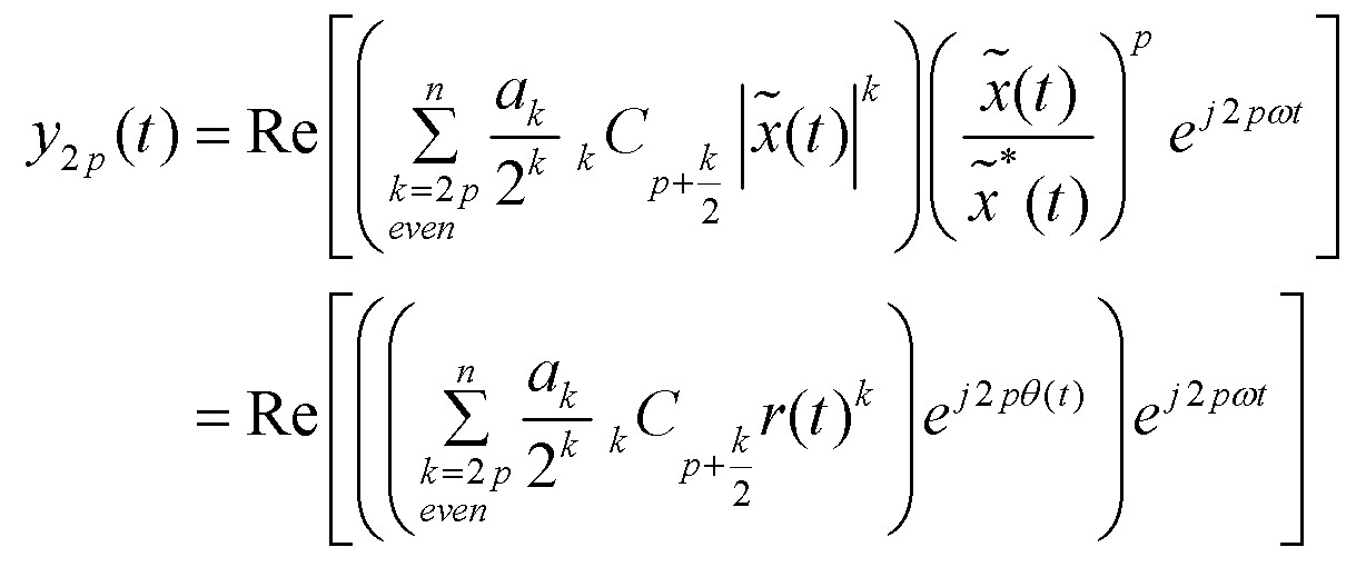

상기 [수학식 3] 및 [수학식 4]로부터 입력 복소 포락선 신호와 m차 고조파 대역 출력 포락선 신호 간의 관계를 하기의 [수학식 5]와 같이 정리할 수 있다.From Equations 3 and 4, the relationship between the input complex envelope signal and the m-th harmonic band output envelope signal can be summarized as in

여기서, n'은 (n-m)을 2로 나눈 몫을 나타내고, 
![]()
![]()
![]()
![]()
실제, 측정신호로부터 AM/AMm과 AM/PMm 추출 시, AM/AMm은 원천주파수 입력 대역 신호와 m차 고조파 대역 신호로 인하여 간단하게 측정할 수 있다. 그러나 AM/PMm의 추출은 다르게 연관된다. 왜냐하면 위상을 보정해야 하기 때문이다.In fact, when extracting AM / AM m and AM / PM m from the measurement signal, AM / AM m can be measured simply due to the source frequency input band signal and the m-th harmonic band signal. However, the extraction of AM / PM m is related differently. This is because the phase must be corrected.
여기서, AM/AMm과 AM/PMm을 시뮬레이션으로 추출하기 위해 원천 주파수 대역의 입력신호와 m차 고조파 대역의 출력신호를 복소 좌표의 실수(Inphase)와 허수(Quadrature) 신호로 사용한다.Here, in order to extract AM / AM m and AM / PM m , the input signal of the source frequency band and the output signal of the m-th harmonic band are used as the complex (inphase) and imaginary (quadature) signals.
입력신호와 출력신호는 m차 고조파로 구성되어 있기 때문에 신호의 크기와 위상이 동기화되어 있지 않다. 따라서 m차 고조파 신호의 크기와 위상을 맞추어 주기 위해서 입력신호를 ![]()
![]()
그리고 입력신호와 출력신호의 지연은 ![]()
![]()
![]()
![]()
![]()
![]()
![]()
![]()
그리고 위상 보정은 복소 신호(I/Q)를 사용하여 조절한다. 즉, 위상 ![]()
![]()
![]()
![]()
![]()
![]()
![]()
![]()
여기서, 위상 추출 시간을 줄이기 위해, 동일한 간격을 가지는 소정 개수(예 : 7개)의 위상값을 대상으로 상관성을 산출하여 상관성이 가장 큰 위상값을 선택 한 후, 상기 소정 개수의 위상값 중에서 상기 선택한 위상값과 가장 가까이 위치한 두 위상값 사이에 있는 각 위상값들과의 상관도를 산출하여 위상 보정 값을 검출한다.Here, in order to reduce the phase extraction time, a correlation is calculated for a predetermined number of phase values having the same interval (for example, seven), and a phase value having the highest correlation is selected. The phase correction value is detected by calculating a correlation between the selected phase value and each phase value between the two nearest phase values.
예를 들어, 360도 전체에 대해 1도씩 변경하면서 위상 보정 값을 검출하기 위해서는 360번의 과정이 필요하다. 따라서 일예로 0도, 45도, 90도, 135도, 180도, 225도, 270도를 최초 대상 위상으로 정한 후, 각각에 대한 상관성을 산출하여 최대 값을 나타내는 위상을 선택한다.For example, in order to detect the phase correction value while changing by 1 degree for the entire 360 degree, 360 steps are required. Therefore, as an example, 0 degrees, 45 degrees, 90 degrees, 135 degrees, 180 degrees, 225 degrees, and 270 degrees are set as the initial target phases, and the correlations for each are selected to select a phase representing the maximum value.
그리고 최초 대상 위상에서 상기 선택한 위상보다 작은 값과 큰 값의 범위 내의 각 위상을 대상으로 위상 보정값을 검출한다. 이때, 상기 선택한 위상이 180도라 하면 135도와 225도 범위에서 1도씩 변경해 가면서 상관성이 가장 큰 위상 보정 값을 검출한다.The phase correction value is detected for each phase within a range of values smaller and larger than the selected phase in the initial target phase. At this time, if the selected phase is 180 degrees, the phase correction value having the highest correlation is detected while changing by 1 degree in the range of 135 degrees and 225 degrees.
결국, 크기 및 위상이 보정된 AM/AMm 함수 및 AM/PMm 함수는 하기의 [수학식 6]과 같다.As a result, the AM / AM m function and the AM / PM m function whose magnitude and phase are corrected are shown in Equation 6 below.


여기서, AM/AMm 및 AM/PMm은 입력신호 ![]()
![]()
![]()
![]()
이하, 사전 왜곡기(220)의 동작에 대해 좀 더 상세히 살펴보기로 한다.Hereinafter, the operation of the
사전 왜곡기(220)의 출력 복소 포락선 신호는 ![]()
![]()
![]()
![]()
여기서, b(t)와 d(t)는 ![]()
![]()
이때, ![]()
![]()
따라서 하기의 [수학식 8]을 만족하는 ![]()
![]()

상기 [수학식 8]을 만족하는 디지털 사전 왜곡기는 선형화를 위해 수치해석적 방식과 LUT(Look Up Table) 방식을 이용한다. 이때, m차 고조파 대역을 선형화시키는 디지털 사전 왜곡기를 DPDm이라고 정의한다.The digital predistorter satisfying Equation 8 uses a numerical analysis method and a look up table (LUT) method for linearization. At this time, a digital predistorter for linearizing the m-th harmonic band is defined as DPD m .
예를 들어, DPD2는 디지털 사전 왜곡기에서 2차 고조파 대역의 출력신호를 선형화시키는 상태를 나타내고, DPD3는 디지털 사전 왜곡기에서 3차 고조파 대역의 출력신호를 선형화시키는 상태를 나타내며, DPD1은 디지털 사전 왜곡기에서 1차 고조파 대역의 출력신호(원천 신호)를 선형화시키는 상태를 나타낸다.For example, DPD 2 represents a state of linearizing an output signal of a second harmonic band in a digital predistorter, DPD 3 represents a state of linearizing an output signal of a third harmonic band in a digital predistorter, and DPD 1 Denotes a state in which the digital predistorter linearizes the output signal (source signal) of the first harmonic band.
이하, 수치해석적 방식에 대해 살펴보기로 한다.Hereinafter, the numerical method will be described.
분석적인 해법을 얻기 위해서 하기의 [수학식 9]와 같이, b(t)에 대한 다항식을 정의한다.In order to obtain an analytical solution, a polynomial for b (t) is defined as shown in Equation 9 below.
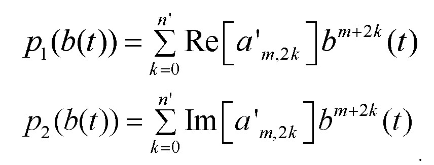
따라서 하기의 [수학식 10]을 만족한다.Therefore, the following [Equation 10] is satisfied.

상기 [수학식 10]은 하기의 [수학식 11]과 같다.
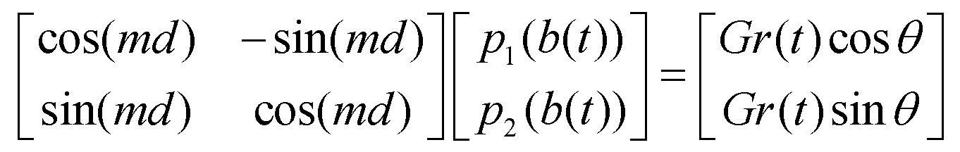
여기서, 역행렬의 배수에 의해 하기의 [수학식 12]와 같은 관계를 얻을 수 있다.Here, the relationship as shown in [Equation 12] can be obtained by the multiple of the inverse matrix.

이때, 상기 [수학식 12]로부터 b(t)는 하기의 [수학식 13]을 만족해야 한다.At this time, b (t) from [Equation 12] should satisfy the following [Equation 13].
![]()
![]()
상기 [수학식 13]은 'Newton'의 방식, 'Secant'의 방식 등과 같은 수치해석 방식을 사용해서 풀 수 있다. 상기 [수학식 13]의 근을 통해 d(t)는 하기의 [수학 식 14]와 같이 추출된다.[Equation 13] can be solved using a numerical method such as 'Newton', 'Secant'. Through the root of Equation 13, d (t) is extracted as shown in Equation 14 below.

결국, DPDm은 하기의 [수학식 15]와 같은 역할을 한다.Finally, DPD m plays the same role as the following [Equation 15].
![]()
![]()
이하, 도 4를 참조하여 LUT를 기본으로 한 방식에 대해 살펴보기로 한다.Hereinafter, a method based on the LUT will be described with reference to FIG. 4.
수치해석적 방식은 낮은 차수의 비선형성 모델에 대해 가용할 수 있다. 그러나 차수가 높아질 경우 b(t)를 찾는데 수렴시간이 많이 걸린다. 따라서 LUT(Loop up table) 방식이 적합하다.Numerical methods are available for low order nonlinear models. However, if the order is high, it takes a long time to find b (t). Therefore, LUT (Loop up table) method is suitable.
즉, AM/AMm과 AM/PMm의 함수를 사용하고, ![]()
![]()
![]()
![]()
도 5 는 본 발명에 따른 고조파 대역 신호의 디지털 사전 왜곡 장치에 대한 성능을 나타내는 일예시도이다.5 is an exemplary view showing the performance of the digital predistortion apparatus of the harmonic band signal according to the present invention.
도 5에 도시된 바와 같이, (a)는 원천 주파수 대역의 입력신호를 나타내고, (b)는 전력 증폭기를 통과한 (a) 신호에서 추출된 3차 고조파 대역의 출력신호를 나타내며, (c)는 제어기(230)에서 3차 고조파를 선택했을 경우 (b)의 3차 고조파 대역의 출력신호를 사전 왜곡시킨 제2의 원천 주파수 대역의 입력신호를 나타내고, (d)는 전력 증폭기를 통과한 제2의 원천 주파수 대역의 입력신호, 즉 3차 고조파 대역의 출력신호를 나타낸다.As shown in FIG. 5, (a) represents an input signal of a source frequency band, (b) represents an output signal of a third harmonic band extracted from a signal (a) that has passed through a power amplifier, and (c) Denotes an input signal of a second source frequency band in which the output signal of the third harmonic band of (b) is pre-distorted when the third harmonic is selected by the
도 6 은 본 발명에 따른 고조파 대역 신호의 디지털 사전 왜곡 장치에 대한 성능을 나타내는 다른 예시도로서, DPD3를 미적용한 경우와 DPD3를 적용한 경우에 있어서, 원천 주파수의 3배를 갖는 고조파 신호의 16-QAM과 64-QAM 신호를 복소 좌표로 나타낸 예시도이다.Figure 6 is a harmonic signal having a triple in the case As another example also, when not applied the DPD 3 and applying the DPD 3, the source frequency of performance of the digital pre-distortion system of the harmonic band signal in accordance with the present invention 16-QAM and 64-QAM signals are shown in complex coordinates.
도 6에 도시된 바와 같이 (a)는 DPD3 미적용 16-QAM 신호를 나타내고, (b)는 DPD3 적용 16-QAM 신호를 나타내며, (c)는 DPD3 미적용 64-QAM 신호를 나타내고, (d)는 DPD3 적용 64-QAM 신호를 나타낸다.The (a) as shown in Figure 6 represents the DPD 3 unapplied 16-QAM signal, (b) the DPD 3 application shows a 16-QAM signal, (c) denotes a DPD 3 unapplied 64-QAM signal, ( d) shows DPD 3 applied 64-QAM signal.
여기서, (a)와 (c)는 3차 고조파 신호에 비선형 왜곡이 발생하여 신호의 형태를 알아볼 수 없지만, (b)와 (d)는 3차 고조파 신호가 선형화되어 신호의 형태를 알아볼 수 있다.Here, (a) and (c) can not recognize the shape of the signal due to the non-linear distortion occurs in the third harmonic signal, but (b) and (d) can determine the shape of the signal by linearizing the third harmonic signal. .
또한, 16-QAM신호에 대한 EVM(Error Vector Magnitude)의 실효치(rms)는 DPD3를 미적용 시 93%이며 DPD3를 적용 시 6.4%이다. 64-QAM에 대한 EVM의 실효치는 DPD3를 미적용 시 88%이며 DPD3를 적용 시 6.5%이다.Further, the effective value (rms) of the EVM (Error Vector Magnitude) of the 16-QAM signal is not applied to 93% when the DPD 3 and is 6.4% when applied to the DPD 3. The effective value of the EVM for the 64-QAM is 88% when unapplied the DPD 3, and is 6.5% when applied to the DPD 3.
이때, EVM은 3차 고주파 출력신호의 노이즈가 크고 여러 메모리 효과로 인하여 완벽하지 않기 때문에, 메모리 효과를 고려한 "Wiener-Hammerstein 모델", "Voterra 모델"을 사용하는 것이 바람직하다.In this case, since the EVM has a high noise of the 3rd high frequency output signal and is not perfect due to various memory effects, it is preferable to use the "Wiener-Hammerstein model" and the "Voterra model" in consideration of the memory effect.
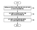
도 7 은 본 발명에 따른 고조파 대역 신호의 디지털 사전 왜곡 방법에 대한 일실시예 흐름도이다.7 is a flowchart illustrating a digital predistortion method of a harmonic band signal according to the present invention.
먼저, 원천(Source) 신호와 상기 원천 신호에 대한 고조파 신호 사이의 크기 변이 및 위상 변이를 추출한다(701).First, a magnitude shift and a phase shift between a source signal and a harmonic signal for the source signal are extracted (701).
이후, 상기 추출한 크기 변이와 위상 변이 각각에 대한 사전 왜곡 파라미터를 산출한다(702).Thereafter, a pre-distortion parameter for each of the extracted magnitude shift and phase shift is calculated (702).
이후, 상기 산출한 사전 왜곡 파라미터를 이용하여 상기 고조파 신호를 사전 왜곡시킨다(703).Thereafter, the harmonic signal is predistorted using the calculated predistortion parameter (703).
한편, 전술한 바와 같은 본 발명의 방법은 컴퓨터 프로그램으로 작성이 가능하다. 그리고 상기 프로그램을 구성하는 코드 및 코드 세그먼트는 당해 분야의 컴퓨터 프로그래머에 의하여 용이하게 추론될 수 있다. 또한, 상기 작성된 프로그램은 컴퓨터가 읽을 수 있는 기록매체(정보저장매체)에 저장되고, 컴퓨터에 의하여 판독되고 실행됨으로써 본 발명의 방법을 구현한다. 그리고 상기 기록매체는 컴퓨터가 판독할 수 있는 모든 형태의 기록매체를 포함한다.On the other hand, the method of the present invention as described above can be written in a computer program. And the code and code segments constituting the program can be easily inferred by a computer programmer in the art. In addition, the written program is stored in a computer-readable recording medium (information storage medium), and read and executed by a computer to implement the method of the present invention. The recording medium may include any type of computer readable recording medium.
이상에서 설명한 본 발명은, 본 발명이 속하는 기술 분야에서 통상의 지식을 가진 자에게 있어 본 발명의 기술적 사상을 벗어나지 않는 범위 내에서 여러 가지 치환, 변형 및 변경이 가능하므로 전술한 실시예 및 첨부된 도면에 의해 한정되는 것이 아니다.The present invention described above is capable of various substitutions, modifications, and changes without departing from the technical spirit of the present invention for those skilled in the art to which the present invention pertains. It is not limited by the drawings.
본 발명은 멀티밴드/멀티모드 송신 시스템 등에 이용될 수 있다.The present invention can be used for a multiband / multimode transmission system and the like.
도 1 은 종래의 디지털 사전 왜곡 장치의 일실시예 구성도,1 is a configuration diagram of an embodiment of a conventional digital predistortion apparatus;
도 2 는 본 발명에 따른 고조파 대역 신호의 디지털 사전 왜곡 장치에 대한 일실시예 구성도,2 is a block diagram of an embodiment of a digital predistortion apparatus of a harmonic band signal according to the present invention;
도 3 은 본 발명에 따른 입력신호와 고조파 출력신호 사이의 비선형성을 나타내는 일예도,3 is an example diagram illustrating nonlinearity between an input signal and a harmonic output signal according to the present invention;
도 4 는 본 발명에 따른 사전 왜곡기의 일실시예 구성도,4 is a configuration diagram of an embodiment of a predistorter according to the present invention;
도 5 는 본 발명에 따른 고조파 대역 신호의 디지털 사전 왜곡 장치에 대한 성능을 나타내는 일예시도5 is an exemplary view illustrating performance of a digital predistortion apparatus of a harmonic band signal according to the present invention.
도 6 은 본 발명에 따른 고조파 대역 신호의 디지털 사전 왜곡 장치에 대한 성능을 나타내는 다른 예시도,6 is another exemplary diagram showing the performance of the digital predistortion apparatus of the harmonic band signal according to the present invention;
도 7 은 본 발명에 따른 고조파 대역 신호의 디지털 사전 왜곡 방법에 대한 일실시예 흐름도이다.7 is a flowchart illustrating a digital predistortion method of a harmonic band signal according to the present invention.
* 도면의 주요 부분에 대한 부호의 설명* Explanation of symbols for the main parts of the drawings
210 : 디지털 신호 처리기(DSP) 220 : 사전 왜곡기(DPD)210: digital signal processor (DSP) 220: predistorter (DPD)
230 : 제어기230: controller
Claims (8)
Priority Applications (1)
| Application Number | Priority Date | Filing Date | Title |
|---|---|---|---|
| KR1020080075223A KR100983599B1 (en) | 2008-07-31 | 2008-07-31 | Digital predistortion device and its method of harmonic band signal |
Applications Claiming Priority (1)
| Application Number | Priority Date | Filing Date | Title |
|---|---|---|---|
| KR1020080075223A KR100983599B1 (en) | 2008-07-31 | 2008-07-31 | Digital predistortion device and its method of harmonic band signal |
Publications (2)
| Publication Number | Publication Date |
|---|---|
| KR20100013613A true KR20100013613A (en) | 2010-02-10 |
| KR100983599B1 KR100983599B1 (en) | 2010-09-27 |
Family
ID=42087587
Family Applications (1)
| Application Number | Title | Priority Date | Filing Date |
|---|---|---|---|
| KR1020080075223A Expired - Fee Related KR100983599B1 (en) | 2008-07-31 | 2008-07-31 | Digital predistortion device and its method of harmonic band signal |
Country Status (1)
| Country | Link |
|---|---|
| KR (1) | KR100983599B1 (en) |
Cited By (1)
| Publication number | Priority date | Publication date | Assignee | Title |
|---|---|---|---|---|
| KR101477715B1 (en) * | 2013-05-06 | 2014-12-30 | 건국대학교 산학협력단 | Harmonic filtered class-e power amplifier with dynamic biasing system and method |
Family Cites Families (1)
| Publication number | Priority date | Publication date | Assignee | Title |
|---|---|---|---|---|
| KR100296982B1 (en) | 1998-11-03 | 2001-10-26 | 오길록 | Predistortion and Delay and Phase Difference Estimation Methods of Transmitter and Transmitted Signal and Feedback Signal in Mixed Linear and Nonlinear Distortion Systems |
-
2008
- 2008-07-31 KR KR1020080075223A patent/KR100983599B1/en not_active Expired - Fee Related
Cited By (1)
| Publication number | Priority date | Publication date | Assignee | Title |
|---|---|---|---|---|
| KR101477715B1 (en) * | 2013-05-06 | 2014-12-30 | 건국대학교 산학협력단 | Harmonic filtered class-e power amplifier with dynamic biasing system and method |
Also Published As
| Publication number | Publication date |
|---|---|
| KR100983599B1 (en) | 2010-09-27 |
Similar Documents
| Publication | Publication Date | Title |
|---|---|---|
| US12176934B2 (en) | Predistortion circuit, method for generating a predistorted baseband signal, control circuit for a predistortion circuit, method to determine parameters for a predistortion circuit, and apparatus and method for predistorting a baseband signal | |
| EP2430748B1 (en) | Pre-distortion for a radio frequency power amplifier | |
| CN102460958B (en) | Apparatus and method for predictive over-drive detection | |
| EP3089414B1 (en) | Digital pre-distortion parameter obtaining method and pre-distortion system | |
| US6072364A (en) | Adaptive digital predistortion for power amplifiers with real time modeling of memoryless complex gains | |
| US9866414B2 (en) | Modulation agnostic digital hybrid mode power amplifier system and method | |
| CN100544193C (en) | Predistorter and amplifying device with distortion compensation function of predistortion method | |
| US7511574B2 (en) | Predistorter | |
| EP2858321B1 (en) | Pre-distortion correction method, pre-distortion correction device, transmitter and base station | |
| CN104604126B (en) | Low sampling rate adaptation scheme for dual-band linearization | |
| US8340602B1 (en) | Power amplifier linearization system and method | |
| KR20180088882A (en) | Digital compensator | |
| KR20130031465A (en) | Apparatus and method for reduced bandwidth envelope tracking and corresponding digital pre-distortion | |
| EP2837093B1 (en) | Digital predistorter (dpd) structure based on dynamic deviation reduction (ddr)-based volterra series | |
| CN101262205A (en) | Predistortion with asymmetric usage of available bandwidth | |
| JP2008294518A (en) | Transmitter | |
| JP2008258713A (en) | Power amplifier | |
| JP2005073032A (en) | Distortion compensation amplification apparatus and distortion compensation method | |
| KR100983599B1 (en) | Digital predistortion device and its method of harmonic band signal | |
| US8633769B2 (en) | Dual loop adaptation digital predistortion architecture for power amplifiers | |
| US20090219088A1 (en) | Apparatus and method for correcting non-linear distortion based on characteristic modeling of high power amplifier | |
| KR20090125597A (en) | Nonlinear Model Parameter Extraction Method of Wideband Signal Using Narrowband Signal, Predistortion Apparatus and Method Using the Same | |
| CN103187932A (en) | Power amplifier and predistorter thereof | |
| Aschbacher et al. | Prototype implementation of two efficient low-complexity digital predistortion algorithms | |
| Gao | Linearization techniques for RF power amplifiers |
Legal Events
| Date | Code | Title | Description |
|---|---|---|---|
| A201 | Request for examination | ||
| PA0109 | Patent application |
St.27 status event code: A-0-1-A10-A12-nap-PA0109 |
|
| PA0201 | Request for examination |
St.27 status event code: A-1-2-D10-D11-exm-PA0201 |
|
| D13-X000 | Search requested |
St.27 status event code: A-1-2-D10-D13-srh-X000 |
|
| R17-X000 | Change to representative recorded |
St.27 status event code: A-3-3-R10-R17-oth-X000 |
|
| D14-X000 | Search report completed |
St.27 status event code: A-1-2-D10-D14-srh-X000 |
|
| PG1501 | Laying open of application |
St.27 status event code: A-1-1-Q10-Q12-nap-PG1501 |
|
| E902 | Notification of reason for refusal | ||
| PE0902 | Notice of grounds for rejection |
St.27 status event code: A-1-2-D10-D21-exm-PE0902 |
|
| P11-X000 | Amendment of application requested |
St.27 status event code: A-2-2-P10-P11-nap-X000 |
|
| P13-X000 | Application amended |
St.27 status event code: A-2-2-P10-P13-nap-X000 |
|
| E701 | Decision to grant or registration of patent right | ||
| GRNT | Written decision to grant | ||
| PE0701 | Decision of registration |
St.27 status event code: A-1-2-D10-D22-exm-PE0701 |
|
| PR0701 | Registration of establishment |
St.27 status event code: A-2-4-F10-F11-exm-PR0701 |
|
| PR1002 | Payment of registration fee |
Fee payment year number: 1 St.27 status event code: A-2-2-U10-U11-oth-PR1002 |
|
| PG1601 | Publication of registration |
St.27 status event code: A-4-4-Q10-Q13-nap-PG1601 |
|
| R18-X000 | Changes to party contact information recorded |
St.27 status event code: A-5-5-R10-R18-oth-X000 |
|
| LAPS | Lapse due to unpaid annual fee | ||
| PC1903 | Unpaid annual fee |
Not in force date: 20130916 Payment event data comment text: Termination Category : DEFAULT_OF_REGISTRATION_FEE St.27 status event code: A-4-4-U10-U13-oth-PC1903 |
|
| PC1903 | Unpaid annual fee |
Ip right cessation event data comment text: Termination Category : DEFAULT_OF_REGISTRATION_FEE Not in force date: 20130916 St.27 status event code: N-4-6-H10-H13-oth-PC1903 |
|
| P22-X000 | Classification modified |
St.27 status event code: A-4-4-P10-P22-nap-X000 |
|
| R18-X000 | Changes to party contact information recorded |
St.27 status event code: A-5-5-R10-R18-oth-X000 |
|
| PN2301 | Change of applicant |
St.27 status event code: A-5-5-R10-R11-asn-PN2301 St.27 status event code: A-5-5-R10-R13-asn-PN2301 |
|
| R18-X000 | Changes to party contact information recorded |
St.27 status event code: A-5-5-R10-R18-oth-X000 |
|
| R18-X000 | Changes to party contact information recorded |
St.27 status event code: A-5-5-R10-R18-oth-X000 |
|
| R18-X000 | Changes to party contact information recorded |
St.27 status event code: A-5-5-R10-R18-oth-X000 |
|
| R18 | Changes to party contact information recorded |
Free format text: ST27 STATUS EVENT CODE: A-5-5-R10-R18-OTH-X000 (AS PROVIDED BY THE NATIONAL OFFICE) |
|
| R18-X000 | Changes to party contact information recorded |
St.27 status event code: A-5-5-R10-R18-oth-X000 |