KR102748300B1 - Removal of electro-oxidized metals during the manufacture of through-mask interconnects - Google Patents
Removal of electro-oxidized metals during the manufacture of through-mask interconnects Download PDFInfo
- Publication number
- KR102748300B1 KR102748300B1 KR1020207005874A KR20207005874A KR102748300B1 KR 102748300 B1 KR102748300 B1 KR 102748300B1 KR 1020207005874 A KR1020207005874 A KR 1020207005874A KR 20207005874 A KR20207005874 A KR 20207005874A KR 102748300 B1 KR102748300 B1 KR 102748300B1
- Authority
- KR
- South Korea
- Prior art keywords
- semiconductor substrate
- metal
- electrolyte
- removal
- cathode
- Prior art date
- Legal status (The legal status is an assumption and is not a legal conclusion. Google has not performed a legal analysis and makes no representation as to the accuracy of the status listed.)
- Active
Links
Images


Classifications
-
- C—CHEMISTRY; METALLURGY
- C25—ELECTROLYTIC OR ELECTROPHORETIC PROCESSES; APPARATUS THEREFOR
- C25F—PROCESSES FOR THE ELECTROLYTIC REMOVAL OF MATERIALS FROM OBJECTS; APPARATUS THEREFOR
- C25F5/00—Electrolytic stripping of metallic layers or coatings
-
- H—ELECTRICITY
- H10—SEMICONDUCTOR DEVICES; ELECTRIC SOLID-STATE DEVICES NOT OTHERWISE PROVIDED FOR
- H10P—GENERIC PROCESSES OR APPARATUS FOR THE MANUFACTURE OR TREATMENT OF DEVICES COVERED BY CLASS H10
- H10P50/00—Etching of wafers, substrates or parts of devices
- H10P50/71—Etching of wafers, substrates or parts of devices using masks for conductive or resistive materials
-
- H01L21/76865—
-
- H—ELECTRICITY
- H10—SEMICONDUCTOR DEVICES; ELECTRIC SOLID-STATE DEVICES NOT OTHERWISE PROVIDED FOR
- H10W—GENERIC PACKAGES, INTERCONNECTIONS, CONNECTORS OR OTHER CONSTRUCTIONAL DETAILS OF DEVICES COVERED BY CLASS H10
- H10W20/00—Interconnections in chips, wafers or substrates
- H10W20/01—Manufacture or treatment
- H10W20/031—Manufacture or treatment of conductive parts of the interconnections
- H10W20/032—Manufacture or treatment of conductive parts of the interconnections of conductive barrier, adhesion or liner layers
- H10W20/054—Manufacture or treatment of conductive parts of the interconnections of conductive barrier, adhesion or liner layers by selectively removing parts thereof
-
- C—CHEMISTRY; METALLURGY
- C25—ELECTROLYTIC OR ELECTROPHORETIC PROCESSES; APPARATUS THEREFOR
- C25D—PROCESSES FOR THE ELECTROLYTIC OR ELECTROPHORETIC PRODUCTION OF COATINGS; ELECTROFORMING; APPARATUS THEREFOR
- C25D5/00—Electroplating characterised by the process; Pretreatment or after-treatment of workpieces
- C25D5/48—After-treatment of electroplated surfaces
-
- C—CHEMISTRY; METALLURGY
- C25—ELECTROLYTIC OR ELECTROPHORETIC PROCESSES; APPARATUS THEREFOR
- C25D—PROCESSES FOR THE ELECTROLYTIC OR ELECTROPHORETIC PRODUCTION OF COATINGS; ELECTROFORMING; APPARATUS THEREFOR
- C25D7/00—Electroplating characterised by the article coated
- C25D7/12—Semiconductors
- C25D7/123—Semiconductors first coated with a seed layer or a conductive layer
-
- C—CHEMISTRY; METALLURGY
- C25—ELECTROLYTIC OR ELECTROPHORETIC PROCESSES; APPARATUS THEREFOR
- C25F—PROCESSES FOR THE ELECTROLYTIC REMOVAL OF MATERIALS FROM OBJECTS; APPARATUS THEREFOR
- C25F3/00—Electrolytic etching or polishing
- C25F3/02—Etching
-
- C—CHEMISTRY; METALLURGY
- C25—ELECTROLYTIC OR ELECTROPHORETIC PROCESSES; APPARATUS THEREFOR
- C25F—PROCESSES FOR THE ELECTROLYTIC REMOVAL OF MATERIALS FROM OBJECTS; APPARATUS THEREFOR
- C25F3/00—Electrolytic etching or polishing
- C25F3/02—Etching
- C25F3/14—Etching locally
-
- C—CHEMISTRY; METALLURGY
- C25—ELECTROLYTIC OR ELECTROPHORETIC PROCESSES; APPARATUS THEREFOR
- C25F—PROCESSES FOR THE ELECTROLYTIC REMOVAL OF MATERIALS FROM OBJECTS; APPARATUS THEREFOR
- C25F3/00—Electrolytic etching or polishing
- C25F3/16—Polishing
- C25F3/22—Polishing of heavy metals
-
- C—CHEMISTRY; METALLURGY
- C25—ELECTROLYTIC OR ELECTROPHORETIC PROCESSES; APPARATUS THEREFOR
- C25F—PROCESSES FOR THE ELECTROLYTIC REMOVAL OF MATERIALS FROM OBJECTS; APPARATUS THEREFOR
- C25F7/00—Constructional parts, or assemblies thereof, of cells for electrolytic removal of material from objects; Servicing or operating
-
- H01L21/76811—
-
- H01L21/76816—
-
- H01L21/7685—
-
- H01L21/76861—
-
- H01L21/76873—
-
- H—ELECTRICITY
- H10—SEMICONDUCTOR DEVICES; ELECTRIC SOLID-STATE DEVICES NOT OTHERWISE PROVIDED FOR
- H10P—GENERIC PROCESSES OR APPARATUS FOR THE MANUFACTURE OR TREATMENT OF DEVICES COVERED BY CLASS H10
- H10P14/00—Formation of materials, e.g. in the shape of layers or pillars
- H10P14/40—Formation of materials, e.g. in the shape of layers or pillars of conductive or resistive materials
- H10P14/46—Formation of materials, e.g. in the shape of layers or pillars of conductive or resistive materials using a liquid
- H10P14/47—Electrolytic deposition, i.e. electroplating; Electroless plating
-
- H—ELECTRICITY
- H10—SEMICONDUCTOR DEVICES; ELECTRIC SOLID-STATE DEVICES NOT OTHERWISE PROVIDED FOR
- H10P—GENERIC PROCESSES OR APPARATUS FOR THE MANUFACTURE OR TREATMENT OF DEVICES COVERED BY CLASS H10
- H10P50/00—Etching of wafers, substrates or parts of devices
- H10P50/60—Wet etching
- H10P50/66—Wet etching of conductive or resistive materials
- H10P50/663—Wet etching of conductive or resistive materials by chemical means only
- H10P50/667—Wet etching of conductive or resistive materials by chemical means only by liquid etching only
-
- H—ELECTRICITY
- H10—SEMICONDUCTOR DEVICES; ELECTRIC SOLID-STATE DEVICES NOT OTHERWISE PROVIDED FOR
- H10P—GENERIC PROCESSES OR APPARATUS FOR THE MANUFACTURE OR TREATMENT OF DEVICES COVERED BY CLASS H10
- H10P72/00—Handling or holding of wafers, substrates or devices during manufacture or treatment thereof
- H10P72/04—Apparatus for manufacture or treatment
- H10P72/0402—Apparatus for fluid treatment
- H10P72/0418—Apparatus for fluid treatment for etching
- H10P72/0422—Apparatus for fluid treatment for etching for wet etching
-
- H—ELECTRICITY
- H10—SEMICONDUCTOR DEVICES; ELECTRIC SOLID-STATE DEVICES NOT OTHERWISE PROVIDED FOR
- H10P—GENERIC PROCESSES OR APPARATUS FOR THE MANUFACTURE OR TREATMENT OF DEVICES COVERED BY CLASS H10
- H10P72/00—Handling or holding of wafers, substrates or devices during manufacture or treatment thereof
- H10P72/04—Apparatus for manufacture or treatment
- H10P72/0451—Apparatus for manufacturing or treating in a plurality of work-stations
- H10P72/0468—Apparatus for manufacturing or treating in a plurality of work-stations comprising a chamber adapted to a particular process
- H10P72/0476—Apparatus for manufacturing or treating in a plurality of work-stations comprising a chamber adapted to a particular process comprising at least one plating chamber
-
- H—ELECTRICITY
- H10—SEMICONDUCTOR DEVICES; ELECTRIC SOLID-STATE DEVICES NOT OTHERWISE PROVIDED FOR
- H10W—GENERIC PACKAGES, INTERCONNECTIONS, CONNECTORS OR OTHER CONSTRUCTIONAL DETAILS OF DEVICES COVERED BY CLASS H10
- H10W20/00—Interconnections in chips, wafers or substrates
- H10W20/01—Manufacture or treatment
- H10W20/031—Manufacture or treatment of conductive parts of the interconnections
- H10W20/032—Manufacture or treatment of conductive parts of the interconnections of conductive barrier, adhesion or liner layers
- H10W20/038—Manufacture or treatment of conductive parts of the interconnections of conductive barrier, adhesion or liner layers covering conductive structures
-
- H—ELECTRICITY
- H10—SEMICONDUCTOR DEVICES; ELECTRIC SOLID-STATE DEVICES NOT OTHERWISE PROVIDED FOR
- H10W—GENERIC PACKAGES, INTERCONNECTIONS, CONNECTORS OR OTHER CONSTRUCTIONAL DETAILS OF DEVICES COVERED BY CLASS H10
- H10W20/00—Interconnections in chips, wafers or substrates
- H10W20/01—Manufacture or treatment
- H10W20/031—Manufacture or treatment of conductive parts of the interconnections
- H10W20/032—Manufacture or treatment of conductive parts of the interconnections of conductive barrier, adhesion or liner layers
- H10W20/042—Manufacture or treatment of conductive parts of the interconnections of conductive barrier, adhesion or liner layers the barrier, adhesion or liner layers being seed or nucleation layers
- H10W20/043—Manufacture or treatment of conductive parts of the interconnections of conductive barrier, adhesion or liner layers the barrier, adhesion or liner layers being seed or nucleation layers for electroplating
-
- H—ELECTRICITY
- H10—SEMICONDUCTOR DEVICES; ELECTRIC SOLID-STATE DEVICES NOT OTHERWISE PROVIDED FOR
- H10W—GENERIC PACKAGES, INTERCONNECTIONS, CONNECTORS OR OTHER CONSTRUCTIONAL DETAILS OF DEVICES COVERED BY CLASS H10
- H10W20/00—Interconnections in chips, wafers or substrates
- H10W20/01—Manufacture or treatment
- H10W20/031—Manufacture or treatment of conductive parts of the interconnections
- H10W20/032—Manufacture or treatment of conductive parts of the interconnections of conductive barrier, adhesion or liner layers
- H10W20/052—Manufacture or treatment of conductive parts of the interconnections of conductive barrier, adhesion or liner layers by treatments not introducing additional elements therein
-
- H—ELECTRICITY
- H10—SEMICONDUCTOR DEVICES; ELECTRIC SOLID-STATE DEVICES NOT OTHERWISE PROVIDED FOR
- H10W—GENERIC PACKAGES, INTERCONNECTIONS, CONNECTORS OR OTHER CONSTRUCTIONAL DETAILS OF DEVICES COVERED BY CLASS H10
- H10W20/00—Interconnections in chips, wafers or substrates
- H10W20/01—Manufacture or treatment
- H10W20/031—Manufacture or treatment of conductive parts of the interconnections
- H10W20/063—Manufacture or treatment of conductive parts of the interconnections by forming conductive members before forming protective insulating material
-
- H—ELECTRICITY
- H10—SEMICONDUCTOR DEVICES; ELECTRIC SOLID-STATE DEVICES NOT OTHERWISE PROVIDED FOR
- H10W—GENERIC PACKAGES, INTERCONNECTIONS, CONNECTORS OR OTHER CONSTRUCTIONAL DETAILS OF DEVICES COVERED BY CLASS H10
- H10W20/00—Interconnections in chips, wafers or substrates
- H10W20/01—Manufacture or treatment
- H10W20/071—Manufacture or treatment of dielectric parts thereof
- H10W20/081—Manufacture or treatment of dielectric parts thereof by forming openings in the dielectric parts
- H10W20/084—Manufacture or treatment of dielectric parts thereof by forming openings in the dielectric parts for dual-damascene structures
- H10W20/087—Manufacture or treatment of dielectric parts thereof by forming openings in the dielectric parts for dual-damascene structures involving multiple stacked pre-patterned masks
-
- H—ELECTRICITY
- H10—SEMICONDUCTOR DEVICES; ELECTRIC SOLID-STATE DEVICES NOT OTHERWISE PROVIDED FOR
- H10W—GENERIC PACKAGES, INTERCONNECTIONS, CONNECTORS OR OTHER CONSTRUCTIONAL DETAILS OF DEVICES COVERED BY CLASS H10
- H10W20/00—Interconnections in chips, wafers or substrates
- H10W20/01—Manufacture or treatment
- H10W20/071—Manufacture or treatment of dielectric parts thereof
- H10W20/081—Manufacture or treatment of dielectric parts thereof by forming openings in the dielectric parts
- H10W20/089—Manufacture or treatment of dielectric parts thereof by forming openings in the dielectric parts using processes for implementing desired shapes or dispositions of the openings, e.g. double patterning
-
- C—CHEMISTRY; METALLURGY
- C25—ELECTROLYTIC OR ELECTROPHORETIC PROCESSES; APPARATUS THEREFOR
- C25D—PROCESSES FOR THE ELECTROLYTIC OR ELECTROPHORETIC PRODUCTION OF COATINGS; ELECTROFORMING; APPARATUS THEREFOR
- C25D17/00—Constructional parts, or assemblies thereof, of cells for electrolytic coating
- C25D17/001—Apparatus specially adapted for electrolytic coating of wafers, e.g. semiconductors or solar cells
-
- C—CHEMISTRY; METALLURGY
- C25—ELECTROLYTIC OR ELECTROPHORETIC PROCESSES; APPARATUS THEREFOR
- C25D—PROCESSES FOR THE ELECTROLYTIC OR ELECTROPHORETIC PRODUCTION OF COATINGS; ELECTROFORMING; APPARATUS THEREFOR
- C25D3/00—Electroplating: Baths therefor
- C25D3/02—Electroplating: Baths therefor from solutions
- C25D3/38—Electroplating: Baths therefor from solutions of copper
-
- C—CHEMISTRY; METALLURGY
- C25—ELECTROLYTIC OR ELECTROPHORETIC PROCESSES; APPARATUS THEREFOR
- C25D—PROCESSES FOR THE ELECTROLYTIC OR ELECTROPHORETIC PRODUCTION OF COATINGS; ELECTROFORMING; APPARATUS THEREFOR
- C25D5/00—Electroplating characterised by the process; Pretreatment or after-treatment of workpieces
- C25D5/02—Electroplating of selected surface areas
- C25D5/022—Electroplating of selected surface areas using masking means
-
- H—ELECTRICITY
- H10—SEMICONDUCTOR DEVICES; ELECTRIC SOLID-STATE DEVICES NOT OTHERWISE PROVIDED FOR
- H10W—GENERIC PACKAGES, INTERCONNECTIONS, CONNECTORS OR OTHER CONSTRUCTIONAL DETAILS OF DEVICES COVERED BY CLASS H10
- H10W70/00—Package substrates; Interposers; Redistribution layers [RDL]
- H10W70/01—Manufacture or treatment
- H10W70/05—Manufacture or treatment of insulating or insulated package substrates, or of interposers, or of redistribution layers
Landscapes
- Chemical & Material Sciences (AREA)
- Engineering & Computer Science (AREA)
- Chemical Kinetics & Catalysis (AREA)
- Electrochemistry (AREA)
- Materials Engineering (AREA)
- Metallurgy (AREA)
- Organic Chemistry (AREA)
- Weting (AREA)
- Electroplating Methods And Accessories (AREA)
- Internal Circuitry In Semiconductor Integrated Circuit Devices (AREA)
- Life Sciences & Earth Sciences (AREA)
- Sustainable Development (AREA)
Abstract
일 구현예에서 웨이퍼 프로세싱 방법은 제 1 피처의 충진 레이트 대 제 2 피처의 충진 레이트의 비가 R1이도록 금속으로 복수의 쓰루-레지스트 리세스된 피처들을 충진하는 단계; 이어서 제 1 피처로부터 금속 제거 레이트 대 제 2 피처로부터 금속 제거 레이트의 비가 R1보다 크도록 금속을 전기화학적으로 제거하여, 충진 균일도를 개선하는 단계를 포함한다. 일부 실시예들에서, 방법은 전해질이 기판의 작업 표면에 실질적으로 평행한 방향의 횡단 플로우 컴포넌트를 갖도록 전해질과 양극성으로 바이어싱된 기판을 콘택트시키는 단계를 포함한다. 방법은 기판의 표면에서 횡단 플로우를 생성하기 위해 구성되는 장치에서 구현될 수 있다. 일부 구현예들에서, 방법은 균일도의 개선을 달성하기 위해 별도의 전기화학적 레짐들의 사용을 형성한다.In one embodiment, a wafer processing method comprises filling a plurality of through-resist recessed features with metal such that a ratio of a fill rate of a first feature to a fill rate of a second feature is R1; and subsequently electrochemically removing the metal such that a ratio of a metal removal rate from the first feature to a metal removal rate from the second feature is greater than R1, thereby improving fill uniformity. In some embodiments, the method comprises contacting an anodically biased substrate with an electrolyte such that the electrolyte has a transverse flow component in a direction substantially parallel to a working surface of the substrate. The method can be implemented in an apparatus configured to generate transverse flow at the surface of the substrate. In some embodiments, the method comprises the use of separate electrochemical regimes to achieve improved uniformity.
Description
관련 출원들의 교차 참조Cross-reference to related applications
본 출원은 2018년 7월 19일 출원되고, 발명자들로서 Thorkelsson 등이 명명된, 명칭이 "Electro-Oxidative Metal Removal in Through Mask Interconnect Fabrication"인, 미국 특허 출원 번호 제 16/040,407 호 및 2017년 7월 28일 출원되고 발명자들로서 Mayer 등이 명명된, 명칭이 "Electro-Oxidative Method and Apparatus for Improving Through Mask Interconnect Uniformity"인 미국 특허 가출원 번호 제 62/538,202 호의 우선권을 주장하고, 이들은 전체가 참조로서 본 명세서에 인용된다.This application claims the benefit of U.S. Patent Application No. 16/040,407, filed July 19, 2018, entitled "Electro-Oxidative Metal Removal in Through Mask Interconnect Fabrication," named Thorkelsson et al. as inventors, and U.S. Provisional Patent Application No. 62/538,202, filed July 28, 2017, entitled "Electro-Oxidative Method and Apparatus for Improving Through Mask Interconnect Uniformity," named Mayer et al. as inventors, which are herein incorporated by reference in their entireties.
본 발명은 전기화학적 금속 제거를 사용하여 금속 층들의 균일도를 개선하기 위한 장치 및 방법에 관한 것이다. 일 구현예에서, 본 발명은 쓰루 마스크 (through mask) 전기도금된 피처들의 웨이퍼 내 (within-wafer), 다이 내 (within-die) 및/또는 피처 내 (within-feature) 균일도를 개선하기 위한 장치 및 방법에 관한 것이다.The present invention relates to an apparatus and method for improving the uniformity of metal layers using electrochemical metal removal. In one embodiment, the present invention relates to an apparatus and method for improving the within-wafer, within-die, and/or within-feature uniformity of through mask electroplated features.
쓰루 마스크 전기도금은 반도체 디바이스 제조시 다수의 프로세싱 스킴들에서 금속 범프들 (bumps) 및 필라들 (pillars) 을 형성하기 위한 방법이다. 쓰루 마스크 전기도금을 활용하는 표준 프로세스들 중 하나는 다음의 단계들을 수반한다. 먼저, 기판 (예를 들어, 평탄한 노출된 표면을 갖는 반도체 기판) 이, PVD (physical vapor deposition) 와 같은, 임의의 적합한 방법에 의해 증착될 수 있는 박형 도전성 시드 층 재료 (예를 들어, Cu, 또는 Ni 시드 층) 로 코팅된다. 다음에, 포토레지스트와 같은 비도전성 마스크 층이 시드 층 위에 증착되고 이어서 리세스된 피처들을 구획하도록 패터닝되고, 패터닝은 리세스된 피처 각각의 하단부에서 시드 층을 노출한다. 패터닝 후에, 기판의 노출된 표면은 필드 영역에 비도전성 마스크의 부분들, 및 리세스된 피처들의 하단 부분들에 도전성 시드 층을 포함한다. Through-mask electroplating is a method for forming metal bumps and pillars in a number of processing schemes during the fabrication of semiconductor devices. One standard process utilizing through-mask electroplating involves the following steps. First, a substrate (e.g., a semiconductor substrate having a flat exposed surface) is coated with a thin conductive seed layer material (e.g., a Cu or Ni seed layer), which may be deposited by any suitable method, such as physical vapor deposition (PVD). Next, a non-conductive mask layer, such as photoresist, is deposited over the seed layer and then patterned to define recessed features, the patterning exposing the seed layer at the bottoms of each of the recessed features. After patterning, the exposed surface of the substrate includes portions of the non-conductive mask in the field region and the conductive seed layer at the bottoms of the recessed features.
다음에, 쓰루 마스크 전기도금 (또는, 포토레지스트의 경우, 쓰루 레지스트 전기도금) 이 이어진다. 쓰루 레지스트 전기도금시, 가장 통상적으로 기판의 주변부에 전기적 콘택트가 시드 층으로 이루어지도록 기판이 전기도금 장치에 위치된다. 장치는 애노드 및 도금될 하나 이상의 금속들의 이온들을 함유하는, 전해질을 하우징한다. 기판은 음극성으로 바이어싱되고 전해질 내로 침지되고, 공식 (1) 로 나타낸 바와 같이, 전해질로부터의 금속 이온들은 기판의 표면에서 환원되고, M은 금속 (예를 들어, 구리) 이고, 그리고 n은 환원 동안 이송된 전자들의 수이다.Next, through-mask electroplating (or, in the case of photoresist, through-resist electroplating) follows. In through-resist electroplating, most commonly, the substrate is positioned in an electroplating apparatus such that electrical contact is made with the seed layer to the periphery of the substrate. The apparatus houses an anode and an electrolyte containing ions of one or more metals to be plated. The substrate is cathodically biased and immersed in the electrolyte, and metal ions from the electrolyte are reduced at the surface of the substrate, as shown by the formula (1), where M is the metal (e.g., copper), and n is the number of electrons transferred during the reduction.
Mn+ + ne →M0 (1)M n+ + ne →M 0 (1)
도전성 시드 층이 리세스된 피처들의 하단 부분들에서만 노출되기 때문에, 전기화학적 증착은 (리세스된 피처들이 금속으로 충진되기 전에) 필드가 아니라, 리세스된 피처들 내에서만 발생하여, 포토레지스트 층 내로 임베딩된 다수의 금속-충진된 리세스들을 발생시킨다. Since the conductive seed layer is exposed only at the bottom portions of the recessed features, electrochemical deposition occurs only within the recessed features, rather than in the field (before the recessed features are filled with metal), resulting in numerous metal-filled recesses embedded within the photoresist layer.
전기도금 후, 예를 들어, 종래의 습식 또는 건식 스트립핑 방법에 의해 마스크가 제거되어, 다수의 독립적인 금속 범프들 또는 필라들을 갖는 기판을 제공한다.After electroplating, the mask is removed, for example by conventional wet or dry stripping methods, providing a substrate having a plurality of independent metal bumps or pillars.
본 명세서에 제공된 배경기술 기술 (description) 은 일반적으로 본 개시의 맥락을 제시하기 위한 것이다. 이 배경기술 섹션에 기술된 정도의 본 명세서에 명명된 발명자들의 업적, 뿐만 아니라 출원시 종래 기술로서 달리 인증되지 않을 수도 있는 본 기술의 양태들은 본 개시에 대한 종래 기술로서 명시적으로나 암시적으로 인정되지 않는다.The background description provided in this specification is generally intended to present the context of the present disclosure. The work of the inventors named in this specification, as well as aspects of the present technology that may not otherwise be recognized as prior art at the time of filing, to the extent described in this background section are not expressly or implicitly admitted as prior art to the present disclosure.
전기-산화 프로세스들을 사용하여, 반도체 기판들 상의 금속 층들의 균일도를 개선하기 위한, 보다 구체적으로 금속-충진된 쓰루 마스크 피처들의 균일도를 개선하기 위한 방법 및 장치가 제공된다. 본 명세서에 제공된 방법들 및 장치들은 전체 웨이퍼에 걸쳐, 다이에 걸쳐, 그리고/또는 금속-충진된 피처 내에서 금속 두께 가변성을 상당히 감소시킬 수 있다. 이에 더하여, 타깃 균일도를 갖는 금속 층을 획득하는 목적을 위해, 본 명세서에 기술된 바와 같이 금속의 전착 (electrodeposition) 이어서 전기평탄화 (electroplanarization) 를 수행하는 툴의 쓰루풋은 일부 실시예들에서, 전착만을 위해 구성되는 툴의 쓰루풋보다 1.5 내지 2 배 클 수 있다. 일부 실시예들에서, 전기평탄화는 적어도 약 2 ㎛/분, 예컨대 약 5 내지 10 ㎛/분의 빠른 금속 제거 레이트들로 수행될 수 있고, 적어도 약 1 ㎛/분, 예컨대 약 2 내지 3 ㎛/분의 증착 레이트들로 상대적으로 빠른 금속의 전착 후에 수행될 수 있다.Methods and apparatus are provided for improving the uniformity of metal layers on semiconductor substrates, more particularly, improving the uniformity of metal-filled through-mask features, using electro-oxidation processes. The methods and apparatus provided herein can significantly reduce metal thickness variability across an entire wafer, across a die, and/or within a metal-filled feature. In addition, for the purpose of obtaining a metal layer having a target uniformity, the throughput of a tool performing electrodeposition of metal followed by electroplanarization as described herein can, in some embodiments, be 1.5 to 2 times greater than the throughput of a tool configured only for electrodeposition. In some embodiments, the electroplanarization can be performed at rapid metal removal rates of at least about 2 μm/min, such as about 5 to 10 μm/min, and can be performed following relatively rapid metal deposition at deposition rates of at least about 1 μm/min, such as about 2 to 3 μm/min.
일 양태에서, 반도체 기판을 프로세싱하기 위한 방법이 제공되고, 방법은 (a) 전기화학적 금속 제거를 위해 구성된 장치로 작업 표면을 갖는 반도체 기판을 제공하는 단계로서, 작업 표면은 노출된 금속 (예를 들어, 구리) 을 포함하는, 반도체 기판을 제공하는 단계; (b) 반도체 기판을 양극성으로 바이어싱하고 반도체 기판의 작업 표면을 전해질 내로 침지시키는 단계; 및 (c) 반도체 기판의 회전 이외의 방법에 의해 반도체 기판의 작업 표면에 실질적으로 평행한 방향으로 반도체 기판의 작업 표면과 콘택트하는 전해질의 횡단 플로우를 제공하는 동안, 노출된 금속의 일부분을 전기화학적으로 제거하고 금속의 균일도를 개선하는 단계를 포함한다. 일부 실시예들에서, 회전은 전해질 플로우의 원인이 될 수도 있지만, 적어도 일부 플로우는 회전 이외의 방법을 사용하여 생성된다. 일부 실시예들에서, 전해질의 횡단 플로우는 전기화학적 금속 제거 시간의 적어도 50 % 동안 제공된다.In one aspect, a method for processing a semiconductor substrate is provided, the method comprising: (a) providing a semiconductor substrate having a working surface in a device configured for electrochemical metal removal, the working surface comprising exposed metal (e.g., copper); (b) anodically biasing the semiconductor substrate and immersing the working surface of the semiconductor substrate into an electrolyte; and (c) providing a transverse flow of electrolyte contacting the working surface of the semiconductor substrate in a direction substantially parallel to the working surface of the semiconductor substrate by a method other than rotation of the semiconductor substrate, while electrochemically removing a portion of the exposed metal and improving the uniformity of the metal. In some embodiments, the rotation may be the cause of the electrolyte flow, although at least some of the flow is generated using a method other than rotation. In some embodiments, the transverse flow of electrolyte is provided for at least 50% of the electrochemical metal removal time.
일부 실시예들에서, 단계 (a) 에서 제공된 반도체 기판의 작업 표면은 노출된 유전체를 더 포함하고, 노출된 금속은 노출된 유전체 아래의 도전성 층 (예를 들어, 금속 시드 층) 에 의해 연결되는 복수의 노출된 금속 피처들 (예를 들어, 쓰루 마스크 피처들) 을 포함한다. 예를 들어, 단계 (a) 에서 제공된 반도체 기판의 작업 표면은 (노출된 유전체로서) 노출된 포토레지스트를 포함할 수도 있고, 기판은 노출된 포토레지스트 아래의 도전성 층에 의해 연결되는, 적어도 약 1:1의 종횡비 (피처의 충진된 부분 및 충진되지 않은 부분 모두를 포함하는 깊이) 를 갖는 복수의 구리-충진된 피처들을 포함할 수도 있고, 구리-충진된 피처들은 적어도 약 50 %까지 구리로 충진된다. In some embodiments, the working surface of the semiconductor substrate provided in step (a) further includes exposed dielectric, and the exposed metal includes a plurality of exposed metal features (e.g., through mask features) connected by a conductive layer (e.g., a metal seed layer) beneath the exposed dielectric. For example, the working surface of the semiconductor substrate provided in step (a) may include exposed photoresist (as the exposed dielectric), and the substrate may include a plurality of copper-filled features having an aspect ratio (a depth including both filled and unfilled portions of the feature) of at least about 1:1, connected by a conductive layer beneath the exposed photoresist, the copper-filled features being at least about 50% filled with copper.
제공된 금속의 전기화학적 제거에 의해 개선된 균일도는 웨이퍼 내 균일도, 다이 내 균일도, 및 피처 내 균일도 중 하나 이상을 포함할 수 있다. 일부 실시예들에서, 전기화학적 금속 제거는 다이 내 균일도 및 피처 내 균일도 모두를 개선한다.The improved uniformity by electrochemical removal of the provided metal may include one or more of within-wafer uniformity, within-die uniformity, and within-feature uniformity. In some embodiments, the electrochemical metal removal improves both within-die uniformity and within-feature uniformity.
일 구현예에서 전해질의 횡단 플로우를 제공하는 단계는 장치의 유입구를 통해 그리고 장치의 유출구로부터 전해질을 흘리는 것을 포함하고, 유입구 및 유출구는 반도체 기판의 작업 표면의 둘레 위치들의 방위각적으로 반대 편에 근접하게 위치된다. 일부 구현예들에서, 횡단 플로우를 제공하는 단계는 왕복 패들 동작으로 횡단 플로우를 형성하는 것을 포함한다. 일부 구현예들에서, 횡단 플로우를 제공하는 단계는 반도체 기판의 작업 표면에 실질적으로 수직인 방향에서 충돌하는 플로우로부터 횡단 플로우로 전해질의 플로우의 방향을 바꾸는 것을 포함한다. 일부 실시예들에서, 전해질의 횡단 플로우는 10 ㎜ 이하의 폭을 갖는 갭에 제공되고, 이 갭은 이온 저항성 이온 침투성 엘리먼트와 기판의 작업 표면 사이에 있다. 일 구현예에서, 갭은 측벽들, 유입구 및 유출구를 갖고, 전해질은 유입구로부터 유출구로 기판의 작업 표면에 실질적으로 평행하게 갭 내에서 흐른다.In one embodiment, the step of providing a transverse flow of electrolyte comprises flowing electrolyte through an inlet of the device and from an outlet of the device, the inlet and the outlet being positioned azimuthally proximate to opposite sides of the circumferential locations of the working surface of the semiconductor substrate. In some embodiments, the step of providing a transverse flow comprises forming the transverse flow by a reciprocating paddle motion. In some embodiments, the step of providing a transverse flow comprises changing the direction of the flow of electrolyte from an impinging flow to a transverse flow in a direction substantially perpendicular to the working surface of the semiconductor substrate. In some embodiments, the transverse flow of electrolyte is provided in a gap having a width of less than 10 mm, the gap being between the ionically resistive ionically permeable element and the working surface of the substrate. In one embodiment, the gap has sidewalls, an inlet, and an outlet, and the electrolyte flows within the gap from the inlet to the outlet substantially parallel to the working surface of the substrate.
바람직하게 횡단 전해질 플로우는 (전해질이 기판 중심에 교차하고 기판의 작업 표면에 평행한 방향으로 기판 중심에 근접한) 기판의 작업 표면의 중심점을 가로질러 적어도 약 3 ㎝/초, 예컨대 적어도 약 10 ㎝/초의 속도를 갖는다. 일부 실시예들에서, 방법은 전기화학적 금속 제거 동안 약 1 내지 30 rpm의 회전 레이트로 반도체 기판을 회전시키는 단계를 더 수반한다.Preferably, the transverse electrolyte flow has a velocity of at least about 3 cm/sec, such as at least about 10 cm/sec, across a center point of the working surface of the substrate (wherein the electrolyte intersects the center of the substrate and is proximate the center of the substrate in a direction parallel to the working surface of the substrate). In some embodiments, the method further comprises rotating the semiconductor substrate at a rotation rate of about 1 to 30 rpm during the electrochemical metal removal.
일부 실시예들에서, 방법은 복수의 쓰루 마스크 피처들을 갖는 기판을 프로세싱하는 단계를 수반하고, 방법은 단계 (a) 및 전기화학적 금속 제거 전에, 단계 (c) 후에 금속을 전기화학적으로 제거한 후 획득된 금속의 타깃 두께보다 적어도 10 % 큰 두께로 복수의 리세스된 피처들 내로 금속을 전기도금하는 단계를 수반한다. 일부 실시예들에서, 금속은 타깃 두께보다 약 20 내지 30 % 큰 두께로 복수의 리세스된 피처들 내로 전기도금된다. 일부 실시예들에서, 전기도금은 전기화학적 금속 제거시 사용되는 전해질과 상이한 전해질에서 수행되고, 일부 구현예들에서, 전기도금 및 전기화학적 금속 제거는 상이한 셀들에서 수행된다. In some embodiments, the method comprises processing a substrate having a plurality of through mask features, the method comprising electroplating metal into the plurality of recessed features to a thickness that is at least 10% greater than a target thickness of the metal obtained after electrochemically removing the metal after step (a) and prior to the electrochemical metal removal. In some embodiments, the metal is electroplated into the plurality of recessed features to a thickness that is about 20 to 30% greater than the target thickness. In some embodiments, the electroplating is performed in an electrolyte that is different from the electrolyte used during the electrochemical metal removal, and in some implementations, the electroplating and the electrochemical metal removal are performed in different cells.
점성 물-기반 (water-based) 전해질 또는 물-함유 (water-containing) 전해질이 많은 실시예들에서, 전기화학적 금속 제거에 바람직하다. 예를 들어, 일부 실시예들에서, 전해질은 적어도 약 4 cp (centipoise), 예컨대 적어도 약 7 cp의 점도를 갖는 도전성 점성 용액이다. 점성 전해질들을 포함하는 일부 예들에서, 전해질은 물과 인산 및/또는 HEDP (1-hydroxyethylidene-1,1 diphosphonic acid) 와 같은 농축된 점성 산을 포함한다. 일부 실시예들에서, 전해질은 침전물을 형성하는 것을 견딜 수 있는, 금속 염들의 매우 과포화된 용액들을 형성할 수 있도록 구성된다. 침전물이 길고 느린 프로세스 후에 이러한 전해질의 형태이면, 침전물은 큰 결정들 대신 비정질 및/또는 수화된 (hydrated) 재료의 미세 입자들의 형태이다. 일부 실시예들에서, 전기화학적 금속 제거시 반도체 기판의 침지를 위해 처음으로 제공된 전해질은 기판의 작업 표면 상에서 노출되는 동일한 금속의 금속 이온들을 포함한다.In many embodiments, a viscous water-based electrolyte or a water-containing electrolyte is preferred for electrochemical metal removal. For example, in some embodiments, the electrolyte is a conductive viscous solution having a viscosity of at least about 4 centipoise (cp), for example at least about 7 centipoise. In some embodiments comprising viscous electrolytes, the electrolyte comprises water and a concentrated viscous acid, such as phosphoric acid and/or 1-hydroxyethylidene-1,1 diphosphonic acid (HEDP). In some embodiments, the electrolyte is configured to form highly supersaturated solutions of metal salts that are capable of resisting the formation of a precipitate. If the precipitate is in the form of such an electrolyte after a long, slow process, the precipitate is in the form of fine particles of amorphous and/or hydrated material instead of large crystals. In some embodiments, the electrolyte initially provided for immersion of the semiconductor substrate during electrochemical metal removal comprises metal ions of the same metal that are exposed on the working surface of the substrate.
일부 실시예들에서, 쓰루 마스크 리세스된 피처들을 포함하는 기판은 본 명세서에 기술된 바와 같이 금속 염, 산, 및 평탄화제 (leveler) 및 억제제로 구성된 그룹으로부터 선택된 적어도 하나의 전기도금 첨가제를 포함하는 전기도금 전해질을 사용하여, 반도체 기판 상의 리세스된 피처들 내로 금속을 먼저 전기도금하고, 이어서 금속을 전기화학적으로 제거하고 균일도를 개선하는 단계에 의해 프로세싱되고, 전기화학적 금속 제거 동안 사용된 전해질은 전기도금 전해질과 상이하고, 적어도 약 4 cp의 점도를 갖는다. 일부 실시예들에서, 전기화학적 금속 제거를 위해 사용된 전해질의 점도는 전기도금에 사용된 전해질의 점도보다 적어도 2배 크다. 일부 실시예들에서, 전기화학적 금속 제거를 위해 사용된 전해질은 전기화학적 억제제들 및 평탄화제 프리이다 (free).In some embodiments, a substrate including through mask recessed features is processed by first electroplating metal into the recessed features on the semiconductor substrate and then electrochemically removing the metal and improving uniformity, using an electroplating electrolyte comprising at least one electroplating additive selected from the group consisting of a metal salt, an acid, and a leveler and a suppressor as described herein, wherein the electrolyte used during the electrochemical metal removal is different from the electroplating electrolyte and has a viscosity of at least about 4 cp. In some embodiments, the viscosity of the electrolyte used for electrochemical metal removal is at least twice as great as the viscosity of the electrolyte used for electroplating. In some embodiments, the electrolyte used for electrochemical metal removal is free of electrochemical suppressors and levelers.
일부 실시예들에서, 노출된 금속을 전기화학적으로 제거하는 단계는: (i) 임계 전위 이하에서 전기에칭 (electroetching), 임계 전위 이상에서 전기연마 (electropolishing), 및 임계 전위 이하에서 전기에칭에 이어 임계 전위 이상에서 전기연마로 구성된 그룹으로부터 전기화학적 금속 제거를 위한 레짐 (regime) 을 선택하는 단계; 및 (ii) 금속 균일도를 개선하기 위해, 선택된 레짐에서 금속의 일부분을 전기화학적으로 제거하는 단계를 포함한다. 노출된 금속의 일부분의 전기화학적 제거는 바람직하게 기준 전극을 사용하여 반도체 기판에 근접한 전위를 모니터링하는 단계를 포함한다.In some embodiments, the step of electrochemically removing the exposed metal comprises: (i) selecting a regime for electrochemical metal removal from the group consisting of electroetching below a critical potential, electropolishing above a critical potential, and electroetching below a critical potential followed by electropolishing above a critical potential; and (ii) electrochemically removing a portion of the metal in the selected regime to improve metal uniformity. The electrochemical removal of the portion of the exposed metal preferably comprises monitoring a potential proximate the semiconductor substrate using a reference electrode.
일부 실시예들에서, 노출된 금속의 일부분을 전기화학적으로 제거하는 단계는 금속 이온들의 농도가 기판으로부터 금속의 전기화학적 제거 과정 동안 타깃 레벨로부터 약 5 %보다 크게 변동하지 (fluctuate) 않도록 타깃 레벨에서 전해질 용액의 금속 이온들의 농도를 유지하는 단계를 포함한다. 일부 실시예들에서, 방법은 금속 균일도를 개선하면서 그리고 전해질 용액 내 금속 이온들의 농도를 타깃 레벨로 유지하는 동안, 금속 이온들의 농도가 복수의 기판들로부터 금속의 전기화학적 제거 과정 동안 타깃 레벨로부터 약 5 %보다 크게 변동하지 않도록, 기판으로부터 전기화학적 금속 제거 후, 순차적으로 동일한 전기화학적 금속 제거 장치의 복수의 반도체 기판들로부터 금속을 전기화학적으로 제거하는 단계를 더 포함한다.In some embodiments, the step of electrochemically removing a portion of the exposed metal comprises maintaining a concentration of metal ions in the electrolyte solution at a target level such that the concentration of the metal ions does not fluctuate by more than about 5% from the target level during the electrochemical removal of the metal from the substrate. In some embodiments, the method further comprises, after the electrochemical metal removal from the substrate, electrochemically removing the metal from the plurality of semiconductor substrates in the same electrochemical metal removal device sequentially such that the concentration of the metal ions does not fluctuate by more than about 5% from the target level during the electrochemical removal of the metal from the plurality of substrates while improving metal uniformity and maintaining the concentration of the metal ions in the electrolyte solution at the target level.
제거될 금속에 대한 확산 계수는 일반적인 거동을 결정하기 위해 그리고 본 명세서에 기술된 전기화학적 금속 제거 프로세스들을 제어하기 위해 중요한 파라미터들 중 하나이다. 확산 계수는 금속 제거 레이트 및 전기연마 천이를 위한 전위들 모두에 영향을 준다. 이온의 확산 계수 및 용액 점도는 이하에 보다 상세히 기술된 바와 같이 Stokes-Einstein 공식에 의해 예시된 바와 같이, 강하게 관련된다. 이 관계로부터, 점도와 확산도 사이에 일반적으로 역전 관계가 있다는 것을 알 수 있다. 예를 들어, 점도의 상승은 확산도로 하여금 감소되게 한다. 확산 계수 (및 관련된 이온 종 모빌리티 (mobility)) 는 대량 이송 한계층에서 그리고 피처 내부에서 확산 대량 이송을 결정하는 중요한 물리화학적 속성들이다. 점도는 또한 전해질 플로우 속도의 분포 및 강도를 결정하는 물리화학적 속성이고, 따라서 대량 이송 한계 층들의 사이즈 및 피처 내부 플로우의 강도를 결정하는 것뿐만 아니라 프로세싱 중인 웨이퍼로부터 그리고 웨이퍼로 일반적인 대량 이송 대류에 중요하다.The diffusion coefficient for the metal to be removed is one of the important parameters for determining the general behavior and for controlling the electrochemical metal removal processes described herein. The diffusion coefficient affects both the metal removal rate and the potentials for the electropolishing transition. The diffusion coefficient of the ions and the viscosity of the solution are strongly related, as illustrated by the Stokes-Einstein equation, as described in more detail below. From this relationship, it can be seen that there is generally an inverse relationship between viscosity and diffusivity. For example, an increase in viscosity causes a decrease in diffusivity. The diffusion coefficient (and the associated ion species mobility) are important physicochemical properties that determine the diffusion mass transport in the mass transport limiting layer and within the feature. Viscosity is also a physicochemical property that determines the distribution and intensity of the electrolyte flow rate, and is therefore important for general mass transport convection to and from the wafer being processed, as well as for determining the size of the mass transport limiting layers and the intensity of the flow within the feature.
일부 실시예들에서, 전기화학적 금속 제거는 이 프로세스에서 핵심 물리화학적 속성들 중 하나인, 전해질 점도를 제어하는 단계를 포함한다. 일부 실시예들에서, 점도 제어는 점도를 직접 (예를 들어, 점도계를 사용하여) 측정하고, 점도를 조정함으로써 (예를 들어, 전해질 유체를 첨가하거나 제거함으로써) 수행된다. 일부 실시예들에서, 점도는 점도와 상관되는 다른 거시적 변수들을 측정함으로써 제어되고 용이하고 신뢰할 수 있게 모니터링될 수 있다. 이러한 거시적 속성들은 이로 제한되는 것은 아니지만, 용액 전도도, 밀도, 광 흡수력, 가시 스펙트럼, UV 스펙트럼, IR 스펙트럼, 용액 굴절률, 또는 음속을 포함한다. 측정된 속성들은 점도로 상관될 수 있거나 측정된 값들이 측정 각각 후에 점도로의 상관을 수행하지 않고 타깃 값들에 가깝게 유지할 수 있다. 일부 실시예들에서, 이들 접근방법들의 조합이 사용될 수 있거나 둘 다 사용될 수 있다. 일부 실시예들에서, 전해질 제어 방법들은 전해질 종 각각의 농도를 측정하는 단계 및 점도가 타깃 값이도록, 이들의 값들을 타깃 값으로 (예를 들어, 타깃 값의 약 10 % 이내 또는 약 5 % 이내) 유지하는 단계를 포함한다. 일부 실시예들에서, 노출된 금속의 일부분을 전기화학적으로 제거하는 단계는 기판으로부터 금속의 전기화학적 제거 과정 동안 점도가 타깃 레벨로부터 미리 결정된 양보다 많이 변동하지 않도록, 타깃 레벨로 전해질 용액의 점도를 유지하는 것을 포함한다. 점도는 전해질 용액의 물 함량, 산 함량, 및/또는 금속 이온 함량에 종속된다. 보다 많은 점도를 감소시키는 경향이 있지만, 보다 많은 산 또는 금속이 점도를 상승시키는 경향이 있다. 일부 실시예들에서, 전해질 점도가 낮으면, 방법들은 점도를 타깃 레벨들로 회복시키기 위해 물을 (예를 들어, 증발에 의해) 제거하는 단계를 수반한다. 일부 경우들에서 전해질 점도는 모든 구성요소들의 농도들을 시간에 걸쳐 일정하게 유지함으로써 (예를 들어, 타깃 농도 이하의 농도를 갖는 전해질 구성요소들을 대체함으로써, 그리고 타깃 명세들 내의 컴포넌트 농도들을 갖는 전해질과 타깃을 벗어난 속성들을 갖는 전해질을 대체함으로써) 유지된다. 다른 경우들에서, 산 및/또는 금속 이온들이 2 개의 별도의 용액들을 사용하여 전해질의 점도를 유지하기 위해 첨가될 수 있고, 제 1 용액은 제 2 용액보다 높은 산 농도를 갖고, 제 2 용액은 제 1 용액보다 높은 금속 이온들의 농도를 갖는다. 일부 실시예들에서, 전기화학적 금속 제거 조건 및 금속 제거 조건 동안 사용된 캐소드 재료는 전기화학적 금속 제거 동안 캐소드에서 수소 (H2) 의 생성을 야기한다. 일부 실시예들에서, 캐소드 재료 및 금속 제거 조건들은 전해질로부터 금속 이온들의 환원으로 인해, 전극 상의 금속의 전착을 야기한다. 일부 실시예들에서, 캐소드에서 H2 생성 및 캐소드 상으로 금속의 전착 모두 기판으로부터 전기화학적 금속 제거 동안 존재한다. 일 구현예에서 양극성으로 바이어싱된 기판 및 캐소드는 캐소드에서 생성된 수소 버블들 및/또는 금속 입자들이 기판과 콘택트하는 것을 방지하는, 이온 침투성 분리기에 의해 분리된다. 일부 실시예들에서, 금속의 일부분을 전기화학적으로 제거하는 단계는 전기화학적 금속 제거 장치의 캐소드에서 H2를 생성하는 단계, 및 H2로 하여금 반도체 기판과 콘택트하게 하지 않고 전해질로부터 H2를 분리하는 단계를 포함한다. 일 구현예에서 전기화학적 금속 제거 장치는 H2 버블들이 캐소드 챔버로부터 애노드 챔버로 이동하는 것을 차단하도록 구성된 이온 침투성 분리기를 포함한다. 일부 실시예들에서, 방법은, 정온 챔버 (stilling chamber) 의 불활성 가스를 H2를 희석하는 단계 및 정온 챔버로부터 희석된 H2를 제거하는 단계를 더 포함한다. 일 구현예들은 하나 이상의 재순환 루프들을 사용한 전기화학적 금속 제거 동안 전해질을 재순환하는 단계를 포함하고, 하나 이상의 재순환 루프들은 전해질 및 전해질 저장소로부터 수소 버블들을 분리하기 위해 구성된 정온 챔버를 포함한다. 일 예에서, 정온 챔버 및 저장소는 일 어셈블리 내에 위치된다. In some embodiments, the electrochemical metal removal comprises a step of controlling the viscosity of the electrolyte, which is one of the key physicochemical properties in the process. In some embodiments, the viscosity control is performed by directly measuring the viscosity (e.g., using a viscometer) and adjusting the viscosity (e.g., by adding or removing electrolyte fluid). In some embodiments, the viscosity can be controlled and easily and reliably monitored by measuring other macroscopic variables that are correlated to viscosity. Such macroscopic properties include, but are not limited to, solution conductivity, density, optical absorbance, visible spectrum, UV spectrum, IR spectrum, solution refractive index, or sound velocity. The measured properties can be correlated to viscosity, or the measured values can be held close to target values without performing a correlation to viscosity after each measurement. In some embodiments, a combination of these approaches can be used, or both can be used. In some embodiments, the electrolyte control methods include measuring the concentration of each of the electrolyte species and maintaining their values at a target value (e.g., within about 10% or within about 5% of the target value) such that the viscosity is at the target value. In some embodiments, the step of electrochemically removing a portion of the exposed metal includes maintaining the viscosity of the electrolyte solution at a target level such that the viscosity does not vary more than a predetermined amount from the target level during the electrochemical removal of the metal from the substrate. The viscosity is dependent on the water content, the acid content, and/or the metal ion content of the electrolyte solution. More acid or metal tends to increase the viscosity, while more water tends to decrease the viscosity. In some embodiments, if the electrolyte viscosity is low, the methods involve removing water (e.g., by evaporation) to restore the viscosity to the target levels. In some cases, the electrolyte viscosity is maintained by keeping the concentrations of all components constant over time (e.g., by replacing electrolyte components having concentrations below the target concentration, and replacing electrolyte having component concentrations within the target specifications with electrolyte having properties outside the target). In other cases, the acid and/or metal ions can be added to maintain the viscosity of the electrolyte using two separate solutions, the first solution having a higher acid concentration than the second solution, and the second solution having a higher concentration of metal ions than the first solution. In some embodiments, the electrochemical metal removal conditions and the cathode material used during the metal removal conditions cause production of hydrogen (H 2 ) at the cathode during the electrochemical metal removal. In some embodiments, the cathode material and the metal removal conditions cause deposition of metal on the electrode due to reduction of metal ions from the electrolyte. In some embodiments, both H 2 production at the cathode and deposition of metal onto the cathode are present during electrochemical metal removal from the substrate. In one embodiment, the bipolarly biased substrate and the cathode are separated by an ion permeable separator that prevents hydrogen bubbles and/or metal particles generated at the cathode from contacting the substrate. In some embodiments, the step of electrochemically removing a portion of the metal comprises generating H 2 at the cathode of the electrochemical metal removal device, and separating the H 2 from the electrolyte without allowing the H 2 to contact the semiconductor substrate. In one embodiment, the electrochemical metal removal device comprises an ion permeable separator configured to block H 2 bubbles from traveling from the cathode chamber to the anode chamber. In some embodiments, the method further comprises diluting the H 2 with an inert gas in a stilling chamber and removing the diluted H 2 from the stilling chamber. Embodiments include recirculating the electrolyte during the electrochemical metal removal using one or more recirculation loops, the one or more recirculation loops comprising a stilling chamber configured to separate hydrogen bubbles from the electrolyte and an electrolyte reservoir. In one example, the stilling chamber and storage are located within the assembly.
일부 실시예들에서, 양극성으로 바이어싱된 기판으로부터 금속의 일부분의 전기화학적 제거는 금속-함유 전해질로부터의 금속을 캐소드 상으로 전착하는 것을 포함한다. 예를 들어, 구리가 기판으로부터 제거될 때, 구리는 전해질로부터 캐소드 상으로 전착될 수도 있다. 캐소드 상으로 금속의 전착을 수반하는 일부 실시예들에서, 장치는 또한 양극성으로 바이어싱된 기판과 캐소드 사이에 이온 침투성 분리기를 채용하여, 애노드 챔버 및 캐소드 챔버를 생성한다. 장치는 일 구현예에서 캐소드를 통해 또는 캐소드에 근접하게 전해질 플로우를 지향시키고 입자들이 웨이퍼 기판에 도달하는 것을 차단하도록 구성된다. 입자들은 이온 도전성 멤브레인 (또는 전해질로 웨팅될 (wet) 때 이온 도전성이 되는 멤브레인) 에 의해 차단되고, 캐소드 챔버로부터 유출구를 통해 그리고/또는 멤브레인을 통해 캐소드 챔버로부터 유체가 흐르도록 지향시키는 것을 돕는다. 일 실시예에서, 제공된 방법은 또한 하나 이상의 재순환 루프들을 사용한 전기화학적 금속 제거 동안 전해질을 재순환시키는 단계를 포함하고, 하나 이상의 재순환 루프들은 외부 욕 (bath) 저장소, 펌프, 필터, 그리고 선택가능하게, 탈기기 (degasser) (질소 및 산소와 같은 용해된 가스들을 제거하기 위한 장치) 를 포함한다. In some embodiments, the electrochemical removal of a portion of the metal from the anodically biased substrate comprises electrodepositing the metal from the metal-containing electrolyte onto the cathode. For example, when copper is removed from the substrate, the copper may be electrodeposited from the electrolyte onto the cathode. In some embodiments involving electrodeposition of the metal onto the cathode, the device also employs an ion permeable separator between the anodically biased substrate and the cathode, creating an anode chamber and a cathode chamber. The device is configured in one embodiment to direct electrolyte flow through or proximate the cathode and block particles from reaching the wafer substrate. The particles are blocked by the ionically conductive membrane (or a membrane that becomes ionically conductive when wetted with the electrolyte) and assist in directing fluid flow from the cathode chamber through an outlet and/or through the membrane to the cathode chamber. In one embodiment, the provided method also includes the step of recirculating the electrolyte during electrochemical metal removal using one or more recirculation loops, the one or more recirculation loops including an external bath reservoir, a pump, a filter, and optionally, a degasser (a device for removing dissolved gases, such as nitrogen and oxygen).
제공된 방법들은 다수의 기판들 상의 균일도를 개선하는데 유용할 수 있지만, 가변 피처 밀도를 갖는 영역들을 갖는 기판들, 뿐만 아니라 가변 종횡비들 및/또는 폭들을 갖는 기판들에 특히 유용하다. 일 실시예에서, 단계 (a) 에서 제공된 반도체 기판은 복수의 쓰루 마스크 피처들을 포함하고, 기판은 적어도 하나의 고립된 (isolated) 피처 및 적어도 2 개의 조밀 피처들을 포함하고, 제 1 조밀 피처는 가장 가까운 피처로부터 제 1 거리만큼 이격되고, 그리고 제 1 고립된 피처는 제 1 거리보다 적어도 2배 큰 제 2 거리만큼 가장 가까운 피처로부터 이격된다. 일 실시예에서, 단계 (a) 에서 제공된 반도체 기판은 복수의 쓰루 마스크 피처들을 포함하고, 제 1 폭을 갖는 제 1 쓰루 마스크 피처 및 상이한, 제 2 폭을 갖는 제 2 쓰루 마스크 피처를 포함한다. 일 실시예에서, 단계 (a) 에서 제공된 반도체 기판은 복수의 쓰루 마스크 피처들을 포함하고, 제 1 종횡비의 리세스를 갖는 제 1 쓰루 마스크 피처 및 상이한, 제 2 종횡비의 리세스를 갖는 제 2 쓰루 마스크 피처를 포함한다. 일 예에서, 리세스들의 종횡비들의 차는, 아래에 놓인 층들의 토포그래피 (topography) 의 변화로 인해 획득된, 유효 종횡비들의 차이다. 일부 실시예들에서, 단계 (a) 에서 제공된 반도체 기판은 복수의 쓰루 마스크 피처들을 포함하고, 제 1 폭 및 제 1 종횡비의 리세스를 갖는 제 1 쓰루 마스크 피처, 제 2 폭 및 제 2 종횡비의 리세스를 갖는 제 2 쓰루 마스크 피처, 제 3 폭 및 제 3 종횡비의 리세스를 갖는 제 3 쓰루 마스크 피처, 및 제 4 폭 및 제 4 종횡비의 리세스를 갖는 제 4 쓰루 마스크 피처를 포함하고, 제 2 폭은 제 1 폭과 상이하고 그리고 제 4 종횡비의 리세스는 제 3 종횡비의 리세스와 상이하다. The provided methods may be useful for improving uniformity on a number of substrates, but are particularly useful for substrates having regions with variable feature densities, as well as substrates having variable aspect ratios and/or widths. In one embodiment, the semiconductor substrate provided in step (a) includes a plurality of through mask features, the substrate including at least one isolated feature and at least two dense features, the first dense feature being spaced apart from the nearest feature by a first distance, and the first isolated feature being spaced apart from the nearest feature by a second distance that is at least twice as large as the first distance. In one embodiment, the semiconductor substrate provided in step (a) includes a plurality of through mask features, the substrate including a first through mask feature having a first width and a second through mask feature having a different, second width. In one embodiment, the semiconductor substrate provided in step (a) includes a plurality of through mask features, a first through mask feature having a recess of a first aspect ratio and a second through mask feature having a recess of a different, second aspect ratio. In one example, a difference in the aspect ratios of the recesses is a difference in effective aspect ratios obtained due to a change in the topography of the underlying layers. In some embodiments, the semiconductor substrate provided in step (a) includes a plurality of through mask features, a first through mask feature having a first width and a first aspect ratio recess, a second through mask feature having a second width and a second aspect ratio recess, a third through mask feature having a third width and a third aspect ratio recess, and a fourth through mask feature having a fourth width and a fourth aspect ratio recess, wherein the second width is different from the first width and the recess of the fourth aspect ratio is different from the recess of the third aspect ratio.
또 다른 양태에서, 반도체 기판을 프로세싱하는 방법이 제공되고, 방법은: (a) 전기화학적 금속 제거를 위해 구성된 장치 내로 작업 표면 (working surface) 을 갖는 반도체 기판을 제공하는 단계로서, 작업 표면은 복수의 쓰루 마스크 금속 피처들 (through mask metal features) 을 포함하는, 반도체 기판을 제공하는 단계; (b) 임계 전위 이하에서 전기에칭 (electroetching), 임계 전위 이상에서 전기연마 (electropolishing), 및 임계 전위 이하에서 전기에칭에 이어 임계 전위 이상에서 전기연마로 구성된 그룹으로부터 전기화학적 금속 제거를 위한 레짐 (regime) 을 선택하는 단계; 및 (c) 금속 균일도를 개선하면서 선택된 레짐에서 쓰루 마스크 금속 피처들로부터 금속의 일부분을 전기화학적으로 제거하는 단계를 포함한다. In another aspect, a method of processing a semiconductor substrate is provided, the method comprising: (a) providing a semiconductor substrate having a working surface into an apparatus configured for electrochemical metal removal, the working surface including a plurality of through mask metal features; (b) selecting a regime for electrochemical metal removal from the group consisting of electroetching below a threshold potential, electropolishing above a threshold potential, and electroetching below a threshold potential followed by electropolishing above a threshold potential; and (c) electrochemically removing a portion of metal from the through mask metal features in the selected regime while improving metal uniformity.
또 다른 양태에서, 반도체 기판을 프로세싱하는 방법이 제공되고, 방법은: (a) 전기화학적 금속 제거를 위해 구성된 장치로 작업 표면을 갖는 반도체 기판을 제공하는 단계로서, 작업 표면은 노출된 금속을 포함하는, 반도체 기판을 제공하는 단계; (b) 반도체 기판을 양극성으로 바이어싱하고 반도체 기판의 작업 표면을 전해질 내로 침지시키는 단계; 및 (c) 임계 전위 이하에서 전기에칭 레짐에서 금속을 제거하고, 이어서 임계 전위 이상에서 전기연마 레짐에서 금속을 제거함으로써 금속의 균일도를 개선하면서 금속의 일부를 전기화학적으로 제거하는 단계를 포함한다. 일 구현예에서, 금속은 구리이고, 그리고 전기화학적 금속 제거는 약 0.1 V 내지 0.7 V의 전위에서 전기에칭, 이어서 약 0.7 V 내지 2.0 V의 전위에서 전기연마를 포함하고, 전위는 구리 기준 전극에 상대적으로 측정되고, 전기연마 동안 사용된 전위는 전기에칭 동안 사용된 전위보다 크다.In another aspect, a method of processing a semiconductor substrate is provided, comprising: (a) providing a semiconductor substrate having a working surface, the working surface comprising exposed metal, with a device configured for electrochemical metal removal; (b) anodically biasing the semiconductor substrate and immersing the working surface of the semiconductor substrate into an electrolyte; and (c) electrochemically removing a portion of the metal while improving uniformity of the metal by removing the metal in an electroetching regime below a threshold potential and subsequently removing the metal in an electropolishing regime above the threshold potential. In one embodiment, the metal is copper, and the electrochemical metal removal comprises electroetching at a potential of about 0.1 V to 0.7 V, followed by electropolishing at a potential of about 0.7 V to 2.0 V, wherein the potentials are measured relative to a copper reference electrode, and wherein the potential used during electropolishing is greater than the potential used during electroetching.
또 다른 양태에서, 하나 이상의 반도체 기판을 프로세싱하는 방법이 제공되고, 방법은: (a) 전기화학적 금속 제거를 위해 구성된 장치로 작업 표면을 갖는 반도체 기판을 제공하는 단계로서, 작업 표면은 노출된 금속을 포함하는, 반도체 기판을 제공하는 단계; (b) 반도체 기판을 양극성으로 바이어싱하고 반도체 기판의 작업 표면을 전해질 용액 내로 침지하는 단계; (c) 금속의 균일도를 개선하면서 금속을 전해질 용액 내로 전기화학적으로 용해시킴으로써 반도체 기판으로부터 금속의 적어도 일부분을 전기화학적으로 제거하는 단계; 및 (d) 금속 이온들의 농도가 기판으로부터 금속의 전기화학적 제거 과정 동안 타깃 레벨로부터 약 5 %보다 크게 변동하지 않도록, 전해질 용액 내 금속 이온들의 농도를 타깃 레벨로 유지하는 단계를 포함한다. In another aspect, a method of processing one or more semiconductor substrates is provided, the method comprising: (a) providing a semiconductor substrate having a working surface with a device configured for electrochemical metal removal, the working surface comprising exposed metal; (b) anodically biasing the semiconductor substrate and immersing the working surface of the semiconductor substrate into an electrolyte solution; (c) electrochemically removing at least a portion of the metal from the semiconductor substrate by electrochemically dissolving the metal into the electrolyte solution while improving uniformity of the metal; and (d) maintaining a concentration of metal ions in the electrolyte solution at a target level such that the concentration of the metal ions does not vary by more than about 5% from the target level during the electrochemical removal of the metal from the substrate.
또 다른 양태에서, 하나 이상의 반도체 기판을 프로세싱하는 방법이 제공되고, 방법은: (a) 전기화학적 금속 제거를 위해 구성된 장치로 작업 표면을 갖는 반도체 기판을 제공하는 단계로서, 작업 표면은 노출된 금속을 포함하는, 반도체 기판을 제공하는 단계; (b) 반도체 기판을 양극성으로 바이어싱하고 반도체 기판의 작업 표면을 전해질 용액 내로 침지하는 단계; (c) 금속의 균일도를 개선하면서 전해질 용액 내로 금속을 전기화학적으로 용해시킴으로써 반도체 기판으로부터 금속의 적어도 일부분을 전기화학적으로 제거하는 단계; 및 (d) 전해질 용액의 점도가 기판으로부터 금속의 전기화학적 제거 과정 동안 타깃 레벨로부터 미리 결정된 양보다 많이 변동하지 않도록, 전해질 용액의 점도를 타깃 레벨로 유지하는 단계를 포함한다.In another aspect, a method of processing one or more semiconductor substrates is provided, the method comprising: (a) providing a semiconductor substrate having a working surface with a device configured for electrochemical metal removal, the working surface comprising exposed metal; (b) anodically biasing the semiconductor substrate and immersing the working surface of the semiconductor substrate into an electrolyte solution; (c) electrochemically removing at least a portion of the metal from the semiconductor substrate by electrochemically dissolving the metal into the electrolyte solution while improving uniformity of the metal; and (d) maintaining a viscosity of the electrolyte solution at a target level such that the viscosity of the electrolyte solution does not vary from the target level by more than a predetermined amount during the electrochemical removal of the metal from the substrate.
또 다른 양태에서, 하나 이상의 반도체 기판을 프로세싱하는 방법이 제공되고, 방법은: (a) 전기화학적 금속 제거를 위해 구성된 장치로 작업 표면을 갖는 반도체 기판을 제공하는 단계로서, 작업 표면은 노출된 금속을 포함하는, 반도체 기판을 제공하는 단계; (b) 반도체 기판을 양극성으로 바이어싱하고 반도체 기판의 작업 표면을 전해질 내로 침지시키는 단계로서, 전해질은 반도체 기판으로부터 제거될 동일한 금속의 이온들을 적어도 약 10 g/L의 농도로 포함하는, 바이어싱 및 침지 단계; 및 (c) 금속의 균일도를 개선하면서 전해질 용액 내로 금속을 전기화학적으로 용해시킴으로써, 반도체 기판으로부터 금속의 일부분을 전기화학적으로 제거하는 단계를 포함한다.In another aspect, a method of processing one or more semiconductor substrates is provided, the method comprising: (a) providing a semiconductor substrate having a working surface with a device configured for electrochemical metal removal, the working surface comprising exposed metal; (b) anodically biasing the semiconductor substrate and immersing the working surface of the semiconductor substrate into an electrolyte, the electrolyte comprising ions of the same metal to be removed from the semiconductor substrate at a concentration of at least about 10 g/L; and (c) electrochemically removing a portion of the metal from the semiconductor substrate by electrochemically dissolving the metal into the electrolyte solution while improving the uniformity of the metal.
또 다른 양태에서, 하나 이상의 반도체 기판을 프로세싱하는 방법이 제공되고, 방법은: (a) 전기화학적 금속 제거를 위해 구성된 장치로 작업 표면을 갖는 반도체 기판을 제공하는 단계로서, 작업 표면은 노출된 금속을 포함하는, 반도체 기판을 제공하는 단계; (b) 반도체 기판을 양극성으로 바이어싱하고 반도체 기판의 작업 표면을 전해질 내로 침지시키는 단계; 및 (c) 금속의 균일도를 개선하면서, 전기화학적 금속 제거 장치의 캐소드에서 H2를 생성하는 동안 그리고 H2 버블들이 양극성으로 바이어싱된 반도체 기판과 콘택트하는 것을 차단하는 동안, 반도체 기판으로부터 금속의 일부분을 전기화학적으로 제거하는 단계를 포함한다.In another aspect, a method of processing one or more semiconductor substrates is provided, the method comprising: (a) providing a semiconductor substrate having a working surface in a device configured for electrochemical metal removal, the working surface including exposed metal; (b) anodically biasing the semiconductor substrate and immersing the working surface of the semiconductor substrate into an electrolyte; and (c) electrochemically removing a portion of the metal from the semiconductor substrate while generating H 2 at a cathode of the electrochemical metal removal device and while blocking H 2 bubbles from contacting the anodically biased semiconductor substrate, while improving uniformity of the metal.
또 다른 양태에서, 하나 이상의 반도체 기판을 프로세싱하는 방법이 제공되고, 방법은: (a) 전기화학적 금속 제거를 위해 구성된 장치로 작업 표면을 갖는 반도체 기판을 제공하는 단계로서, 작업 표면은 노출된 금속을 포함하는, 반도체 기판을 제공하는 단계; (b) 반도체 기판을 양극성으로 바이어싱하고 반도체 기판의 작업 표면을 전해질 내로 침지시키는 단계; 및 (c) 금속의 균일도를 개선하면서, 반도체 기판으로부터 금속의 일부분을 전기화학적으로 제거하는 단계로서, 장치는 양극성으로 바이어싱된 기판을 하우징하는 애노드 챔버 및 캐소드를 하우징하는 캐소드 챔버를 포함하고, 챔버들은 이온 침투성 멤브레인에 의해 분리되는, 전기화학적 제거 단계를 포함한다. 일 실시예에서, 방법은 금속이 기판으로부터 전기화학적으로 제거되는 동안, 금속을 캐소드 상으로 전착하는 단계를 포함한다. 또 다른 양태에서, 반도체 기판을 프로세싱하는 방법이 제공되고, 방법은: (a) 전기화학적 금속 제거를 위해 구성된 장치 내로 복수의 쓰루 마스크 금속 피처들을 갖는 반도체 기판을 제공하는 단계; (b) 반도체 기판을 양극성으로 바이어싱하고 반도체 기판의 작업 표면을 전해질 내로 침지하는 단계; (c) 개별 쓰루 마스크 피처들 내 금속 두께 변동이 감소되도록, 쓰루 마스크 금속 피처들로부터 금속의 일부분을 전기화학적으로 제거하는 단계를 포함한다. In another aspect, a method of processing one or more semiconductor substrates is provided, the method comprising: (a) providing a semiconductor substrate having a working surface into a device configured for electrochemical metal removal, the working surface including exposed metal; (b) anodically biasing the semiconductor substrate and immersing the working surface of the semiconductor substrate into an electrolyte; and (c) electrochemically removing a portion of the metal from the semiconductor substrate while improving uniformity of the metal, the device comprising an anode chamber housing the anodically biased substrate and a cathode chamber housing a cathode, the chambers being separated by an ion permeable membrane. In one embodiment, the method comprises electrodepositing a metal onto the cathode while the metal is electrochemically removed from the substrate. In another aspect, a method of processing a semiconductor substrate is provided, the method comprising: (a) providing a semiconductor substrate having a plurality of through mask metal features into a device configured for electrochemical metal removal; (b) a step of positively biasing the semiconductor substrate and immersing a working surface of the semiconductor substrate into an electrolyte; and (c) a step of electrochemically removing a portion of the metal from the through mask metal features such that metal thickness variation within individual through mask features is reduced.
또 다른 양태에서, 반도체 기판을 프로세싱하는 방법이 제공되고, 방법은: (a) 복수의 쓰루 마스크 리세스된 피처들을 갖고 쓰루 마스크 피처 각각의 하단부에 노출된 도전성 시드 층을 갖는 반도체 기판을 전기도금 장치 내로 제공하는 단계; (b) 금속염, 산 및 전기도금의 균일도를 개선하기 위해 구성된 하나 이상의 전기도금 첨가제들을 포함하는 전해질을 사용하여 전기도금 장치에서 금속으로 쓰루 마스크 리세스된 피처들을 적어도 부분적으로 충진하는 단계로서, 제 1 쓰루 마스크 피처의 충진 레이트 대 제 2 쓰루 마스크 피처의 충진 레이트의 비는 R1인, 적어도 부분적으로 충진하는 단계; (c) 기판을 전기화학적 금속 제거를 위해 구성된 장치로 이송하는 단계; 및 (d) 적어도 약 4 cp의 점도를 갖고 전기도금 전해질과 상이한, 전해질 내의, 쓰루 마스크 금속 피처들로부터 금속의 일부분을 전기화학적으로 제거함으로써 전기도금된 금속의 균일도를 개선하는 단계로서, 제 1 쓰루 마스크 피처의 전기화학적 금속 제거 레이트 대 제 2 쓰루 마스크 피처 내 전기화학적 금속 제거 레이트의 비는 R1보다 큰, 균일도 개선 단계를 포함한다.In another aspect, a method of processing a semiconductor substrate is provided, the method comprising: (a) providing a semiconductor substrate having a plurality of through mask recessed features and a conductive seed layer exposed at a lower portion of each of the through mask features into an electroplating apparatus; (b) at least partially filling the through mask recessed features with metal in the electroplating apparatus using an electrolyte comprising a metal salt, an acid, and one or more electroplating additives configured to improve the uniformity of the electroplating, wherein a ratio of a fill rate of the first through mask feature to a fill rate of the second through mask feature is R1; (c) transferring the substrate to an apparatus configured for electrochemical metal removal; and (d) improving the uniformity of the electroplated metal by electrochemically removing a portion of the metal from the through-mask metal features in an electrolyte different from the electroplating electrolyte and having a viscosity of at least about 4 cp, wherein a ratio of the electrochemical metal removal rate of the first through-mask feature to the electrochemical metal removal rate in the second through-mask feature is greater than R1.
제공된 방법들은 반도체 기판 상의 층들의 패터닝을 위해 사용된 포토리소그래픽 기법들과 통합될 수 있다. 일부 실시예들에서, 제공된 방법들은 포토레지스트를 반도체 기판에 도포하는 단계; 포토레지스트를 광에 노출하는 단계; 포토레지스트를 패터닝하고 패턴을 반도체 기판으로 전사하는 단계; 및 반도체 기판으로부터 포토레지스트를 선택적으로 제거하는 단계를 더 포함한다.The provided methods can be integrated with photolithographic techniques used for patterning layers on a semiconductor substrate. In some embodiments, the provided methods further comprise applying a photoresist to a semiconductor substrate; exposing the photoresist to light; patterning the photoresist and transferring the pattern to the semiconductor substrate; and selectively removing the photoresist from the semiconductor substrate.
또 다른 양태에서, 반도체 기판으로부터 금속을 전기화학적으로 제거하기 위한 장치가 제공되고, 장치는: (a) 반도체 기판으로부터 전기화학적 금속 제거 동안 전해질 및 캐소드를 홀딩하도록 구성된 용기 (vessel); (b) 반도체 기판의 작업 표면이 전해질 내로 침지되고 반도체 기판으로부터 금속의 전기화학적 제거 동안 캐소드로부터 분리되도록, 반도체 기판을 홀딩하도록 구성된 반도체 기판 홀더; (c) 반도체 기판의 작업 표면에 실질적으로 평행한 방향으로 반도체 기판의 작업 표면과 콘택트하는 전해질의 횡단 플로우를 제공하도록 구성된 메커니즘으로서, 메커니즘은 반도체 기판을 회전시키기 위한 메커니즘과 상이한, 전해질의 횡단 플로우를 제공하도록 구성된 메커니즘; 및 (d) 반도체 기판에 근접한 전위 또는 등가 전위를 측정하기 위한 기준 전극을 포함한다. In another aspect, a device for electrochemically removing metal from a semiconductor substrate is provided, the device comprising: (a) a vessel configured to hold an electrolyte and a cathode during electrochemical metal removal from the semiconductor substrate; (b) a semiconductor substrate holder configured to hold a semiconductor substrate such that a working surface of the semiconductor substrate is immersed into the electrolyte and separated from the cathode during electrochemical removal of the metal from the semiconductor substrate; (c) a mechanism configured to provide a transverse flow of the electrolyte contacting the working surface of the semiconductor substrate in a direction substantially parallel to the working surface of the semiconductor substrate, the mechanism configured to provide a transverse flow of the electrolyte being different from a mechanism for rotating the semiconductor substrate; and (d) a reference electrode for measuring a potential or an equivalent potential proximate the semiconductor substrate.
또 다른 양태에서, 반도체 기판으로부터 금속을 전기화학적으로 제거하기 위한 장치가 제공되고, 장치는: (a) 양극성으로 바이어싱된 반도체 기판으로부터 전기화학적 금속 제거 동안 전해질 및 수소 생성 캐소드를 홀딩하도록 (holding) 구성되는 용기로서, 양극성으로 바이어싱된 반도체 기판을 하우징하도록 구성된 애노드 챔버 및 수소 생성 캐소드를 하우징하도록 구성된 캐소드 챔버를 포함하는 용기; (b) 애노드 챔버와 캐소드 챔버 사이의 이온 침투성 분리기로서, 캐소드 챔버로부터 애노드 챔버로 수소 버블들의 이송을 억제 또는 방지하도록 구성되는 이온 침투성 분리기; (c) 반도체 기판으로부터 금속의 전기화학적 제거 동안, 반도체 기판의 작업 표면이 전해질 내로 침지되고 가스 생성 캐소드로부터 분리되도록, 양극성으로 바이어싱된 반도체 기판을 홀딩하도록 구성된 반도체 기판 홀더; 및 (d) 캐소드 챔버와 유체로 연통하는 정온 챔버로서, 정온 챔버는 캐소드 챔버로부터 음극액을 수용하고 그리고 수용된 전해질로부터 수소 버블들을 격리하고 (segregate) 제거하도록 구성되는 정온 챔버를 포함한다.In another aspect, a device for electrochemically removing metal from a semiconductor substrate is provided, the device comprising: (a) a vessel configured to hold an electrolyte and a hydrogen generating cathode during electrochemical metal removal from an anodically biased semiconductor substrate, the vessel comprising an anode chamber configured to house the anodically biased semiconductor substrate and a cathode chamber configured to house the hydrogen generating cathode; (b) an ion permeable separator between the anode chamber and the cathode chamber, the ion permeable separator configured to inhibit or prevent transport of hydrogen bubbles from the cathode chamber to the anode chamber; (c) a semiconductor substrate holder configured to hold the anodically biased semiconductor substrate such that a working surface of the semiconductor substrate is immersed in the electrolyte and separated from the gas generating cathode during electrochemical removal of the metal from the semiconductor substrate; and (d) a still chamber in fluid communication with the cathode chamber, the still chamber including a still chamber configured to receive catholyte from the cathode chamber and to segregate and remove hydrogen bubbles from the received electrolyte.
또 다른 양태에서, 반도체 기판으로부터 금속을 전기화학적으로 제거하기 위한 장치가 제공되고, 장치는: (a) 반도체 기판으로부터 전기화학적 금속 제거 동안 양극성으로 바이어싱된 반도체 기판을 하우징하도록 구성된 애노드 챔버로서, 유체를 애노드 챔버로 도입하기 위한 적어도 하나의 유입구를 갖는 애노드 챔버; (b) 캐소드를 하우징하도록 구성된 캐소드 챔버로서, 캐소드 챔버 내로 유체를 도입하기 위한 적어도 하나의 유입구를 갖는 캐소드 챔버; 및 (c) 애노드 챔버와 캐소드 챔버 사이에 이온 침투성 분리기를 포함한다.In another aspect, a device for electrochemically removing metal from a semiconductor substrate is provided, the device comprising: (a) an anode chamber configured to house a semiconductor substrate that is positively biased during electrochemical metal removal from the semiconductor substrate, the anode chamber having at least one inlet for introducing a fluid into the anode chamber; (b) a cathode chamber configured to house a cathode, the cathode chamber having at least one inlet for introducing a fluid into the cathode chamber; and (c) an ion permeable separator between the anode chamber and the cathode chamber.
또 다른 양태에서, 반도체 기판으로부터 금속을 전기화학적으로 제거하기 위한 장치가 제공되고, 장치는: (a) 양극성으로 바이어싱된 반도체 기판으로부터 전기화학적 금속 제거 동안 전해질 및 캐소드 기판을 홀딩하기 위해 구성된 용기로서, 양극성으로 바이어싱된 반도체 기판을 하우징하도록 구성된 애노드 챔버 및 반도체 기판으로부터 제거되는 동일한 금속 종이 전착되는 캐소드를 하우징하도록 구성된 캐소드 챔버를 포함하는 용기; (b) 애노드 챔버와 캐소드 챔버 사이의 이온 침투성 분리기; (c) 반도체 기판의 작업 표면이 전해질 내로 침지되고 반도체 기판으로부터 금속의 전기화학적 제거 동안 캐소드로부터 분리되도록 양극성으로 바이어싱된 반도체 기판을 홀딩하도록 구성된 반도체 기판 홀더; 및 (d) 캐소드 챔버와 유체로 연통되고, 캐소드 챔버로부터 음극액을 수용하고 음극액을 필터하도록 구성되는 전해질 재순환 루프를 포함한다. In another aspect, an apparatus for electrochemically removing metal from a semiconductor substrate is provided, the apparatus comprising: (a) a vessel configured to hold an electrolyte and a cathode substrate during electrochemical metal removal from an anodically biased semiconductor substrate, the vessel comprising an anode chamber configured to house the anodically biased semiconductor substrate and a cathode chamber configured to house a cathode on which the same metal species to be removed from the semiconductor substrate is electrodeposited; (b) an ion permeable separator between the anode chamber and the cathode chamber; (c) a semiconductor substrate holder configured to hold the anodically biased semiconductor substrate such that a working surface of the semiconductor substrate is immersed in the electrolyte and separated from the cathode during electrochemical removal of the metal from the semiconductor substrate; and (d) an electrolyte recirculation loop in fluid communication with the cathode chamber, the electrolyte recirculation loop configured to receive catholyte from the cathode chamber and filter the catholyte.
또 다른 양태에서, 반도체 기판으로부터 금속을 전기화학적으로 제거하기 위한 장치가 제공되고, 장치는: (a) 반도체 기판으로부터 전기화학적 금속 제거 동안 전해질 및 캐소드를 홀딩하도록 구성된 용기로서, 반도체 기판을 하우징하도록 구성된 애노드 챔버 및 캐소드를 하우징하도록 구성된 캐소드 챔버를 포함하는 용기, 장치는 전기화학적 금속 제거 동안 반도체 기판을 양극성으로 바이어스하도록 구성됨; (b) 애노드 챔버와 캐소드 챔버 사이의 이온 침투성 분리기; 및 (c) 반도체 기판의 작업 표면이 전해질 내로 침지되고 반도체 기판으로부터 금속의 전기화학적 제거 동안 가스 생성 캐소드를 분리되도록 양극성으로 바이어싱된 반도체 기판을 홀딩하도록 구성된 반도체 기판 홀더를 포함하고; 장치는 캐소드 챔버의 유입구를 통해 캐소드 챔버로 유체를 첨가하도록 구성된다. 일부 실시예들에서, 캐소드는 수소 생성 캐소드이고, 그리고 이온 침투성 분리기는 수소가 기판과 콘택트되는 것을 차단한다. 일부 실시예들에서, 이온 침투성 분리기는 캐소드에서 생성될 수 있는 입자들이 기판에 콘택트하는 것을 차단한다.In another aspect, a device for electrochemically removing metal from a semiconductor substrate is provided, the device comprising: (a) a vessel configured to hold an electrolyte and a cathode during electrochemical metal removal from the semiconductor substrate, the vessel comprising an anode chamber configured to house the semiconductor substrate and a cathode chamber configured to house the cathode, the device configured to anodically bias the semiconductor substrate during the electrochemical metal removal; (b) an ion permeable separator between the anode chamber and the cathode chamber; and (c) a semiconductor substrate holder configured to hold the semiconductor substrate so that a working surface of the semiconductor substrate is immersed in the electrolyte and a gas generating cathode is separated during the electrochemical removal of the metal from the semiconductor substrate; and the device is configured to add a fluid to the cathode chamber through an inlet of the cathode chamber. In some embodiments, the cathode is a hydrogen generating cathode, and the ion permeable separator blocks hydrogen from contacting the substrate. In some embodiments, the ion permeable separator blocks particles that may be generated at the cathode from contacting the substrate.
또 다른 양태에서, 반도체 기판으로부터 금속을 전기화학적으로 제거하기 위한 장치가 제공되고, 장치는: (a) 반도체 기판으로부터 전기화학적 금속 제거 동안 전해질 및 캐소드를 홀딩하도록 구성된 용기로서, 반도체 기판을 하우징하도록 구성된 애노드 챔버 및 캐소드를 하우징하도록 구성된 캐소드 챔버를 포함하는 용기, 장치는 전기화학적 금속 제거 동안 반도체 기판을 양극성으로 바이어싱하도록 구성됨; (b) 애노드 챔버와 캐소드 챔버 사이의 이온 침투성 분리기; (c) 반도체 기판의 작업 표면이 전해질 내로 침지되고 반도체 기판으로부터 금속의 전기화학적 제거 동안 가스 생성 캐소드로부터 분리되도록 양극성으로 바이어싱된 반도체 기판을 홀딩하도록 구성된 반도체 기판 홀더; 장치는 양극액 재순환 루프 및 음극액 재순환 루프를 포함하고, 루프들은 공유된 부분을 갖고, 장치는 루프들의 공유된 부분으로부터 애노드 챔버로 그리고 캐소드 챔버로 규정된 양들의 전해질을 개별적으로 전달하도록 구성된다. 또 다른 구현예에서, 양극액 재순환 루프 및 음극액 재순환 루프는 공유된 부분을 갖지만, 장치는 루프의 공유되지 않은 부분들로부터 애노드 챔버로 그리고 캐소드 챔버로 규정된 양들의 전해질을 개별적으로 전달하도록 구성된다. 예를 들어, 양극액 재순환 루프는 양극액 챔버에 유체로 연결된 전용 전해질 저장소 유체를 가질 수도 있고, 그리고 음극액 재순환 루프는 음극액 챔버에 유체로 연결된 별도의 전해질 저장소를 가질 수도 있다. 또한, 다른 실시예들에서, 양극액 재순환 루프 및 음극액 재순환 루프는 공유된 부분들을 갖지 않는다. In another aspect, a device for electrochemically removing metal from a semiconductor substrate is provided, the device comprising: (a) a vessel configured to hold an electrolyte and a cathode during electrochemical metal removal from the semiconductor substrate, the vessel comprising an anode chamber configured to house the semiconductor substrate and a cathode chamber configured to house the cathode, the device configured to anodically bias the semiconductor substrate during the electrochemical metal removal; (b) an ion permeable separator between the anode chamber and the cathode chamber; (c) a semiconductor substrate holder configured to hold a semiconductor substrate anodically biased such that a working surface of the semiconductor substrate is immersed in the electrolyte and separated from a gas generating cathode during the electrochemical removal of metal from the semiconductor substrate; the device comprising an anolyte recirculation loop and a catholyte recirculation loop, the loops having a shared portion, the device configured to individually deliver prescribed amounts of electrolyte from the shared portion of the loops to the anode chamber and to the cathode chamber. In another embodiment, the anolyte recirculation loop and the catholyte recirculation loop have shared portions, but the device is configured to individually deliver prescribed amounts of electrolyte from non-shared portions of the loops to the anode chamber and to the cathode chamber. For example, the anolyte recirculation loop may have a dedicated electrolyte reservoir fluidly connected to the anolyte chamber, and the catholyte recirculation loop may have a separate electrolyte reservoir fluidly connected to the catholyte chamber. Additionally, in other embodiments, the anolyte recirculation loop and the catholyte recirculation loop do not have shared portions.
또 다른 양태에서, 반도체 기판으로부터 금속을 전기화학적으로 제거하기 위한 장치가 제공되고, 장치는: (a) 반도체 기판으로부터 전기화학적 금속 제거 동안 전해질 및 캐소드를 홀딩하기 위해 구성된 용기, 장치는 전기화학적 금속 제거 동안 반도체 기판을 양극성으로 바이어스하도록 구성됨; (b) 반도체 기판의 작업 표면이 전해질 내로 침지되고 반도체 기판으로부터 금속의 전기화학적 제거 동안 캐소드로부터 분리되도록, 반도체 기판을 홀딩하도록 구성된 반도체 기판 홀더; (c) 용기로 희석액을 첨가하기 위한 용기의 유입구; (d) 용기로부터 전해질을 제거하기 위한 용기의 유출구; 및 (e) 전기화학적 금속 제거 동안 전해질 내 금속 이온들의 농도 및 산의 농도를 측정하기 위한 적어도 2 개의 측정 디바이스들을 포함한다.In another aspect, an apparatus for electrochemically removing metal from a semiconductor substrate is provided, the apparatus comprising: (a) a vessel configured to hold an electrolyte and a cathode during electrochemical metal removal from the semiconductor substrate, the vessel configured to positively bias the semiconductor substrate during the electrochemical metal removal; (b) a semiconductor substrate holder configured to hold a semiconductor substrate such that a working surface of the semiconductor substrate is immersed into the electrolyte and separated from the cathode during the electrochemical removal of the metal from the semiconductor substrate; (c) an inlet of the vessel for adding a diluent to the vessel; (d) an outlet of the vessel for removing electrolyte from the vessel; and (e) at least two measurement devices for measuring a concentration of metal ions and a concentration of an acid in the electrolyte during the electrochemical metal removal.
또 다른 양태에서, 장치가 제공되고, 장치는 전기화학적 금속 제거를 위해 구성된 용기 및 본 명세서에 제공된 임의의 방법들을 수행하기 위한 프로그램 인스트럭션들을 포함하는 제어기를 포함한다. In another aspect, a device is provided, the device comprising a container configured for electrochemical metal removal and a controller including program instructions for performing any of the methods provided herein.
또 다른 양태에서, 시스템이 제공되고, 시스템이 본 명세서에 제공된 임의의 장치들 및 스텝퍼를 포함한다. In another aspect, a system is provided, the system comprising any of the devices provided herein and a stepper.
또 다른 양태에서, 시스템이 제공되고, 시스템은 전기도금 장치 및 본 명세서에 기술된 전기화학적 금속 제거를 위한 임의의 장치들을 포함한다.In another aspect, a system is provided, the system comprising an electroplating apparatus and any of the devices for electrochemical metal removal described herein.
또 다른 양태에서, 본 명세서에 제공된 방법들 중 임의의 방법을 수행하기 위한 코드를 포함하는 비일시적 컴퓨터 판독가능 매체가 제공된다.In another aspect, a non-transitory computer-readable medium comprising code for performing any of the methods provided herein is provided.
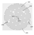
또 다른 양태에서, 전기화학적 금속 제거를 위한 캐소드가 제공되고, 캐소드는: (a) 복수의 채널들, 캐소드의 바디를 통해 전해질을 전달하기 위해 구성되는 채널들; 및 (b) 캐소드의 에지의 복수의 만입부들을 포함한다. 일부 실시예들에서, 캐소드는 일반적으로 디스크 형상 바디를 갖는다. 일부 실시예들에서, 채널들은 캐소드의 도전성 표면 위로 연장하는 비도전성 튜브들과 피팅된다.In another aspect, a cathode for electrochemical metal removal is provided, the cathode comprising: (a) a plurality of channels, the channels configured to conduct electrolyte through a body of the cathode; and (b) a plurality of indentations in an edge of the cathode. In some embodiments, the cathode has a generally disc-shaped body. In some embodiments, the channels are fitted with non-conductive tubes extending over a conductive surface of the cathode.
또 다른 양태에서, 전기화학적 금속 제거를 위한 캐소드가 제공되고, 캐소드는 일반적으로 디스크 형상 바디를 갖고 캐소드의 도전성 표면 상의 복수의 비도전성 고정 (fixation) 엘리먼트들을 포함하고, 고정 엘리먼트들은 하나 이상의 핸들들에 부착될 수 있게 구성된다. 이러한 캐소드는 금속이 캐소드 표면 상에 전착된 후 장치로부터 용이하게 제거될 수 있다. 일부 실시예들에서, 비도전성 고정 엘리먼트들은 일반적으로 디스크 형상 캐소드의 상이한 방사상 위치들에 배치된다. In another aspect, a cathode for electrochemical metal removal is provided, the cathode having a generally disc-shaped body and including a plurality of non-conductive fixation elements on a conductive surface of the cathode, the fixation elements being configured to be attachable to one or more handles. The cathode can be readily removed from the device after metal is deposited on the cathode surface. In some embodiments, the non-conductive fixation elements are disposed at different radial locations of the generally disc-shaped cathode.
또 다른 양태에서, 전기화학적 금속 제거를 위한 장치가 제공되고, 장치는 본 명세서에 기술된 바와 같이 캐소드를 홀딩하는 용기를 포함한다.In another aspect, a device for electrochemical metal removal is provided, the device comprising a container holding a cathode as described herein.
또 다른 양태에서, 전기화학적 금속 제거를 위한 전해질을 형성하는 방법이 제공된다. 일부 실시예들에서, 방법은 인산에 금속 옥사이드 및/도는 금속 하이드록사이드를 용해시키는 단계; 및 이어서 보다 농축된 인산으로 금속 옥사이드 및/도는 하이드록사이드의 용해 후 획득된 용액을 조합하는 단계 및 적어도 약 4 cp의 점도를 갖는 전해질을 형성하는 단계를 수반한다. 본 발명의 이들 및 다른 특징들 및 장점들은 연관된 도면들을 참조하여 이하에 보다 상세히 기술될 것이다. In another aspect, a method of forming an electrolyte for electrochemical metal removal is provided. In some embodiments, the method comprises the steps of dissolving a metal oxide and/or metal hydroxide in phosphoric acid; and then combining the solution obtained after dissolution of the metal oxide and/or hydroxide with more concentrated phosphoric acid, and forming an electrolyte having a viscosity of at least about 4 cp. These and other features and advantages of the present invention will be described in more detail below with reference to the associated drawings.
도 1a 내지 도 1d는 본 명세서에 제공된 실시예들에 따른 프로세싱을 겪는 기판의 개략적인 단면도들이다.
도 2a는 본 명세서에 제공된 실시예들에 따른 프로세스를 예시하는 프로세스 흐름도이다.
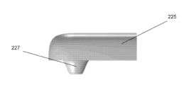
도 2b는 일 실시예에 따른, 머쉬룸-형 금속 돌출부들로 금속 충진 후 기판의 개략적인 단면도이다.
도 2c는 금속 충진 및 마스크 제거 후 필라 및 비아를 조합한 피처의 개략적인 단면도이다.
도 2d는 금속 충진 및 마스크 제거 후 라인 및 비아를 조합한 피처의 개략적인 단면도이다.
도 3a 내지 도 3d는 본 명세서에 제공된 실시예들에 따른 프로세싱을 겪는 기판의 개략적인 단면도들이다.
도 4는 본 명세서에 제공된 실시예들에 따른 프로세스를 예시하는 프로세스 흐름도이다.
도 5a 및 도 5b는 다이 내 불균일도 및 피처 내 불균일도의 결정을 각각 예시하는 기판들의 개략적인 단면도이다.
도 6은 본 명세서에 제공된 일 실시예에 따른 전기화학적 금속 제거 프로세스를 예시하는 프로세스 흐름도이다.
도 7a 및 도 7b는 2 개의 상이한 실시예들에 따른 전해질 플로우 패턴들을 예시하는 기판에 근접한 금속 제거 장치의 부분들의 개략적인 단면도이다.
도 8은 본 명세서에 제공된 일 실시예에 따른 전기화학적 금속 제거 프로세스를 예시하는 프로세스 흐름도이다.
도 9a는 전기에칭을 겪는 예시적인 기판의 단면도이다.
도 9b는 전기연마를 겪는 예시적인 기판의 단면도이다.
도 9c는 전기연마 후 도 9b에 도시된 기판의 단면도이다.
도 10은 전기에칭 레짐 및 전기연마 레짐의 결정시 사용된 임계 전위를 추정하기 위한 실험적 I-V 도이다.
도 11은 전해질 교차 플로우 레이트에 대한 임계 전위의 종속성을 예시하는 일련의 실험적 I-V 곡선들이다.
도 12는 임계 전위의 결정시 사용된 2 개의 실험적 플롯들을 예시한다.
도 13은 본 명세서에 제공된 일 실시예에 따른 전기화학적 금속 제거 프로세스를 예시하는 프로세스 흐름도이다.
도 14는 본 명세서에 제공된 일 실시예에 따른 전기화학적 금속 제거 프로세스를 예시하는 프로세스 흐름도이다.
도 15a는 과에칭 (overetching) 문제를 예시하는 전기에칭 후 기판의 개략적인 단면도이다.
도 15b 내지 도 15e는 본 명세서에 제공된 실시예들에 따른, 전기에칭 이어서 전기연마를 겪는 기판의 개략적인 단면도들이다.
도 16a는 전기화학적 금속 제거 없이 획득된 구리 피처의 SEM 사진이다.
도 16b는 전기연마 레짐에서 전기평탄화된 구리 피처의 SEM 사진이다.
도 16c는 전기에칭 레짐에서 전기평탄화된 구리 피처의 SEM 사진이다.
도 16d는 전기에칭 이어서 전기연마에 의해 전기평탄화된 구리 피처의 SEM 사진이다.
도 17은 본 명세서에 제공된 실시예에 따른 프로세스를 위한 프로세스 흐름도이다.
도 18은 본 명세서에 제공된 실시예에 따른 프로세스를 위한 프로세스 흐름도이다.
도 19a는 본 명세서에 제공된 실시예에 따른 제어기 연결성의 개략적 표현이다.
도 19b는 본 명세서에 제공된 실시예에 따른 셀에서 재료들이 들어오고 나가는 것의 개략적 표현이다.
도 20은 본 명세서에 제공된 실시예에 따른 전기화학적 금속 제거 장치의 도금 제거 셀 (deplating cell) 의 개략적 단면도이다.
도 21은 본 명세서에 제공된 실시예에 따른, 상부에 배치된 교차 플로우 한정 구조체를 갖는 이온 저항성 이온 침투성 엘리먼트의 평면도다.
도 22a는 본 명세서에 제공된 실시예에 따른, 캐소드 챔버로부터 H2 버블 제거를 예시하는, 도금 제거 셀의 일부분의 개략적 단면도이다.
도 22b는 기울어진 (slanted) 멤브레인을 예시하는, 대안적인 실시예에 따른 도금 제거 셀의 개략적인 단면도이다.
도 23은 본 명세서에 제공된 실시예에 따른, 도금 제거 셀의 일부분의 개략적 단면도이다.
도 24는 본 명세서에 제공된 실시예에 따른, 전기화학적 금속 제거 장치에서 유체 연통성을 예시하는 개략적인 표현이다.
도 25는 본 명세서에 제공된 또 다른 실시예에 따른, 전기화학적 금속 제거 장치에서 유체 연통성을 예시하는 개략적 표현이다.
도 26은 본 명세서에 제공된 실시예에 따른, 전해질 저장소와 조합하여 도시된 정온 챔버의 개략적 단면도이다.
도 27은 본 명세서에 제공된 실시예에 따른, 전해질 저장소의 개략적인 단면도이다.
도 28a는 본 명세서에 제공된 실시예에 따른 활성 캐소드를 하우징하는 도금 제거 셀의 일부분의 개략적 단면도이다.
도 28b는 금속 층이 활성 캐소드 상으로 증착된 후 도 28a에 도시된 도금 제거 셀의 단면도이다.
도 29a는 본 명세서에 제공된 실시예에 따른 캐소드의 평면도이다.
도 29b는 캐소드의 쓰루홀 내로 피팅하도록 구성된 튜브의 일부분의 도면이다.
도 29c는 도 29a에 예시된 캐소드의 도면이다.
도 29d는 캐소드 제거를 위해 캐소드에 부착된 핸들들을 도시하는 도 29a에 예시된 캐소드의 도면이다.
도 30은 본 명세서에 제공된 실시예들에 따른 동작들을 수행하기 위해 사용될 수도 있는 통합된 시스템의 개략적인 평면도이다.
도 31은 본 명세서에 제공된 실시예들에 따른 동작들을 수행하기 위해 사용될 수도 있는 또 다른 통합된 시스템의 개략적인 평면도이다.
도 32는 본 명세서에 제공된 일 예에 따른 정상 상태 구리 농도의 함수로서 전해질 제거 레이트의 종속성을 예시하는 컴퓨팅 모델링 플롯이다.FIGS. 1A through 1D are schematic cross-sectional views of a substrate undergoing processing according to embodiments provided herein.
FIG. 2a is a process flow diagram illustrating a process according to embodiments provided herein.
FIG. 2b is a schematic cross-sectional view of a substrate after metal filling with mushroom-shaped metal protrusions according to one embodiment.
Figure 2c is a schematic cross-sectional view of a feature combining pillars and vias after metal filling and mask removal.
Figure 2d is a schematic cross-sectional view of a feature combining lines and vias after metal filling and mask removal.
FIGS. 3A through 3D are schematic cross-sectional views of a substrate undergoing processing according to embodiments provided herein.
FIG. 4 is a process flow diagram illustrating a process according to embodiments provided herein.
Figures 5a and 5b are schematic cross-sectional views of substrates illustrating the determination of within-die non-uniformity and within-feature non-uniformity, respectively.
FIG. 6 is a process flow diagram illustrating an electrochemical metal removal process according to one embodiment provided herein.
FIGS. 7A and 7B are schematic cross-sectional views of portions of a metal removal device proximate the substrate illustrating electrolyte flow patterns according to two different embodiments.
FIG. 8 is a process flow diagram illustrating an electrochemical metal removal process according to one embodiment provided herein.
Figure 9a is a cross-sectional view of an exemplary substrate undergoing electroetching.
Figure 9b is a cross-sectional view of an exemplary substrate undergoing electropolishing.
Figure 9c is a cross-sectional view of the substrate shown in Figure 9b after electropolishing.
Figure 10 is an experimental IV diagram for estimating the critical potential used in determining the electroetching regime and electropolishing regime.
Figure 11 is a series of experimental IV curves illustrating the dependence of the critical potential on the electrolyte cross-flow rate.
Figure 12 illustrates two experimental plots used in the determination of the critical potential.
FIG. 13 is a process flow diagram illustrating an electrochemical metal removal process according to one embodiment provided herein.
FIG. 14 is a process flow diagram illustrating an electrochemical metal removal process according to one embodiment provided herein.
Figure 15a is a schematic cross-sectional view of a substrate after electroetching illustrating an overetching problem.
FIGS. 15b to 15e are schematic cross-sectional views of a substrate undergoing electroetching followed by electropolishing according to embodiments provided herein.
Figure 16a is a SEM image of a copper feature obtained without electrochemical metal removal.
Figure 16b is a SEM image of an electroplanarized copper feature in an electropolishing regime.
Figure 16c is a SEM image of an electroplanarized copper feature in an electroetching regime.
Figure 16d is a SEM image of a copper feature that was electroplanarized by electroetching followed by electropolishing.
Figure 17 is a process flow diagram for a process according to an embodiment provided herein.
Figure 18 is a process flow diagram for a process according to an embodiment provided herein.
FIG. 19a is a schematic representation of controller connectivity according to an embodiment provided herein.
FIG. 19b is a schematic representation of the flow of materials into and out of a cell according to an embodiment provided herein.
FIG. 20 is a schematic cross-sectional view of a deplating cell of an electrochemical metal removal device according to an embodiment provided herein.
FIG. 21 is a plan view of an ion-resistant ion-permeable element having a cross-flow confining structure disposed thereon, according to an embodiment provided herein.
FIG. 22A is a schematic cross-sectional view of a portion of a plating removal cell illustrating H 2 bubble removal from a cathode chamber according to an embodiment provided herein.
FIG. 22b is a schematic cross-sectional view of a plating removal cell according to an alternative embodiment, illustrating a slanted membrane.
FIG. 23 is a schematic cross-sectional view of a portion of a plating removal cell according to an embodiment provided herein.
FIG. 24 is a schematic representation illustrating fluid communication in an electrochemical metal removal device according to an embodiment provided herein.
FIG. 25 is a schematic representation illustrating fluid communication in an electrochemical metal removal device according to another embodiment provided herein.
FIG. 26 is a schematic cross-sectional view of a stilling chamber illustrated in combination with an electrolyte reservoir, according to an embodiment provided herein.
FIG. 27 is a schematic cross-sectional view of an electrolyte storage according to an embodiment provided herein.
FIG. 28a is a schematic cross-sectional view of a portion of a plating removal cell housing an active cathode according to an embodiment provided herein.
Figure 28b is a cross-sectional view of the plating removal cell shown in Figure 28a after the metal layer has been deposited onto the active cathode.
FIG. 29a is a plan view of a cathode according to an embodiment provided herein.
FIG. 29b is a drawing of a portion of a tube configured to fit into a through-hole in a cathode.
Figure 29c is a drawing of the cathode illustrated in Figure 29a.
FIG. 29d is a drawing of the cathode illustrated in FIG. 29a showing handles attached to the cathode for cathode removal.
FIG. 30 is a schematic plan view of an integrated system that may be used to perform operations according to embodiments provided herein.
FIG. 31 is a schematic plan view of another integrated system that may be used to perform operations according to embodiments provided herein.
Figure 32 is a computational modeling plot illustrating the dependence of electrolyte removal rate as a function of steady-state copper concentration according to an example provided herein.
이하의 상세한 기술에서, 개시된 구현예들의 완전한 이해를 제공하기 위해 다수의 구체적인 구현예들이 제시된다. 그러나, 당업자에게 자명할 바와 같이, 개시된 구현예들은 대안적인 엘리먼트들 또는 프로세스들을 사용함으로써 또는 이들 구체적인 상세들 없이 실시될 수도 있다. 다른 예들에서, 공지의 프로세스들, 절차들, 및 컴포넌트들은 개시된 구현예들의 양태들을 불필요하게 모호하게 하지 않도록 상세히 기술되지 않았다.In the following detailed description, numerous specific implementation examples are set forth in order to provide a thorough understanding of the disclosed implementations. However, as will be apparent to those skilled in the art, the disclosed implementations may be practiced using alternative elements or processes or without these specific details. In other instances, well-known processes, procedures, and components have not been described in detail so as not to unnecessarily obscure aspects of the disclosed implementations.
반도체 기판들 상의 금속 층들의 균일도를 개선하기 위한 방법들 및 장치들이 제공된다. 이 기술에서, 용어 "반도체 웨이퍼" 또는 "반도체 기판"은 기판의 바디 내 어디든 반도체 재료를 갖는 기판을 지칭하고, 반도체 재료가 노출될 필요가 없다는 것이 이해된다. 반도체 기판은 반도체 재료 위에 형성된 하나 이상의 유전체 층 및 도전성 층을 포함할 수도 있다. 반도체 디바이스 산업에서 사용된 웨이퍼는 통상적으로 원형 반도체 기판이다. 예들은 200 ㎜, 또는 300 ㎜, 또는 450 ㎜의 직경을 갖는 웨이퍼들을 포함한다. 이하의 상세한 기술은 웨이퍼 상의 증착 및 에칭을 기술한다. 그러나, 개시된 구현예들은 이렇게 제한되지 않는다. 워크피스는 다양한 형상들, 사이즈들, 및 재료들일 수도 있다. 반도체 웨이퍼들에 더하여, 개시된 구현예들의 장점을 취할 수도 있는 다른 워크피스들은 인쇄 회로 기판들 등과 같은 다양한 물품들을 포함한다. Methods and apparatus for improving the uniformity of metal layers on semiconductor substrates are provided. In this technology, the term "semiconductor wafer" or "semiconductor substrate" refers to a substrate having semiconductor material anywhere within the body of the substrate, and it is understood that the semiconductor material need not be exposed. The semiconductor substrate may include one or more dielectric layers and conductive layers formed over the semiconductor material. Wafers used in the semiconductor device industry are typically circular semiconductor substrates. Examples include wafers having a diameter of 200 mm, or 300 mm, or 450 mm. The detailed description below describes deposition and etching on the wafer. However, the disclosed embodiments are not so limited. The workpiece may have various shapes, sizes, and materials. In addition to semiconductor wafers, other workpieces that may benefit from the disclosed embodiments include various articles such as printed circuit boards.
본 명세서에 제공된 방법들은 다양한 금속 층들, 구체적으로 전기화학적 용해를 용이하게 받을 수 있는 Cu, Ni, Co, Sn, 및 이들 금속들을 포함하는 합금들과 같은 금속들의 균일도를 개선하도록 사용될 수 있다. 일부 실시예들에서, Pd, Pt, Ag, Rh, Ru, Ir, 및 Au와 같은, 이들 금속들을 포함하는 보다 귀금속들이 제공된 방법들을 사용하여 전기평탄화된다. 제공된 방법들을 사용하여 전기평탄화될 수 있는 합금의 일 예는 주석 은 합금이다 (예를 들어, 5 atomic % 이하의 은을 함유하는 합금).The methods provided herein can be used to improve the uniformity of various metal layers, particularly metals such as Cu, Ni, Co, Sn, and alloys including these metals that are readily amenable to electrochemical dissolution. In some embodiments, more noble metals including these metals, such as Pd, Pt, Ag, Rh, Ru, Ir, and Au, are electroplanarized using the methods provided. One example of an alloy that can be electroplanarized using the methods provided is a tin silver alloy (e.g., an alloy containing less than 5 atomic % silver).
전기화학적 용해는 반도체 기판이 양극성으로 바이어스될 때, 공식 (2) 로 도시된 반응에 따라 발생한다.Electrochemical dissolution occurs when the semiconductor substrate is bipolarly biased according to the reaction shown in Equation (2).
M0 →Mn+ + ne- (2)M0→Mn++ ne- (2)
전기화학적 금속 제거를 위한 장치는 전력 공급부에 전기적으로 접속된 캐소드를 더 포함하고, 장치는 전기화학적 금속 제거 동안 애노드를 음성으로 바이어스하도록 구성된다. 캐소드는 전해질로부터 금속을 환원하고, 이는 이어서 통상적으로 캐소드의 표면 상에 도금되고 그리고/또는 전해질로부터 양성자들을 환원함으로써 H2를 생성한다. 일부 실시예들에서, 캐소드는 금속 이온들을 상당히 환원하지 않고 실질적으로 배타적으로 H2를 생성하도록 선택된다. 다른 실시예들에서, 캐소드는 H2를 생성하지 않고, 금속 이온들을 실질적으로 배타적으로 환원하도록 선택된다. 또 다른 실시예들에서, H2의 생성 및 금속 이온들의 환원 모두 캐소드에서 상당한 양으로 발생할 수 있다. 본 명세서에 사용된 바와 같이, 금속 이온 환원 이외의 반응들을 우세하게 유발하는 (예를 들어, H2를 우세하게 생성하는) 캐소드들은 불활성 캐소드들로 지칭되는 한편, 금속 이온들을 금속으로 우세하게 환원하는 캐소드들은 활성 캐소드들로 지칭된다. 불활성 캐소드들은 통상적으로 백금과 같은 촉매 수소 생성에 원인이 되는 금속을 포함한다. 활성 캐소드는 통상적으로 스테인리스 스틸 표면, 구리 표면, 등과 같은 임의의 도금가능 표면을 가질 수 있다. 전해질 농도 및 캐소드에 제공된 전력과 같은 프로세스 조건들은 수소 생성과 금속 이온 환원 반응들 간의 밸런싱 (balance) 에 영향을 줄 수 있다는 것을 주의한다. 예를 들어, 금속 이온 환원은 보다 높은 농도들의 금속을 갖는 전해질들이 사용될 때 보다 촉진된다 (favor).The device for electrochemical metal removal further comprises a cathode electrically connected to a power supply, wherein the device is configured to negatively bias the anode during the electrochemical metal removal. The cathode reduces metal from the electrolyte, which in turn is typically plated onto a surface of the cathode and/or reduces protons from the electrolyte to produce H 2 . In some embodiments, the cathode is selected to substantially exclusively produce H 2 without significantly reducing metal ions. In other embodiments, the cathode is selected to substantially exclusively reduce metal ions without significantly producing H 2 . In still other embodiments, both the production of H 2 and the reduction of metal ions can occur in significant amounts at the cathode. As used herein, cathodes that predominantly cause reactions other than metal ion reduction (e.g., predominantly produce H 2 ) are referred to as inactive cathodes, while cathodes that predominantly reduce metal ions to metal are referred to as active cathodes. Inert cathodes typically comprise a metal responsible for catalytic hydrogen production, such as platinum. The active cathode can typically have any plateable surface, such as a stainless steel surface, a copper surface, etc. Note that process conditions, such as electrolyte concentration and power provided to the cathode, can affect the balance between hydrogen production and metal ion reduction reactions. For example, metal ion reduction is favored when electrolytes having higher concentrations of metal are used.
용어들 "전기화학적 금속 제거" 및 "전기화학적 에칭 백"은 본 명세서에서 상호교환가능하게 사용되고 양극성으로 바이어싱된 기판으로부터 금속의 전기화학적 용해를 지칭한다. "전기평탄화"는 임의의 타입의 균일도의 개선 (즉, 웨이퍼 레벨, 다이 레벨, 및 피처 레벨의 두께 변화를 포함하는 임의의 타입의 금속 두께 변화의 감소) 을 동반하는 전기화학적 금속 제거에 대한 일반적인 용어로서 본 명세서에 사용된다. 전기화학적 금속 제거 및 전기평탄화는 본 명세서에서 상세히 논의될, 별개의 "전기에칭" 레짐 및 "전기연마" 레짐에서 수행될 수 있다. The terms "electrochemical metal removal" and "electrochemical etch back" are used interchangeably herein and refer to the electrochemical dissolution of metal from an anodically biased substrate. "Electroplanarization" is used herein as a general term for electrochemical metal removal accompanied by any type of improvement in uniformity (i.e., reduction in any type of metal thickness variation, including wafer level, die level, and feature level thickness variation). Electrochemical metal removal and electroplanarization can be performed in separate "electroetch" and "electropolishing" regimes, which are discussed in detail herein.
본 명세서에 사용된 바와 같이 용어 "피처"는 문맥으로부터 명확해질 바와 같이, 충진되지 않은, 부분적으로 충진된, 또는 완전히 충진된 기판 상의 리세스를 지칭할 수 있다. 쓰루 마스크 피처들은 포토레지스트 층 내와 같이 유전체 마스크 층 내에 형성된 충진되지 않은, 부분적으로 충진된, 또는 완전히 충진된 리세스된 피처들을 지칭하고, 마스크 층은 나중에 제거되도록 의도된다. 쓰루 마스크 피처들은 하단부에 도전성 시드 층을 갖는다. 달리 말하면, 충진되지 않은 또는 부분적으로 충진된 쓰루 마스크 피처들을 갖는 기판들은 노출된 불연속적인 금속 층 및 노출된 유전체 층을 포함하고, 노출된 불연속적인 금속 층은 유전체 층 밑의 도전성 층에 의해 전기적으로 접속된다.As used herein, the term "feature" may refer to a recess in a substrate that is unfilled, partially filled, or completely filled, as will be clear from the context. Through mask features refer to unfilled, partially filled, or completely filled recessed features formed in a dielectric mask layer, such as in a photoresist layer, wherein the mask layer is intended to be removed later. The through mask features have a conductive seed layer underneath. In other words, substrates having unfilled or partially filled through mask features include an exposed discontinuous metal layer and an exposed dielectric layer, wherein the exposed discontinuous metal layer is electrically connected to the conductive layer beneath the dielectric layer.
일 양태에서, 쓰루 마스크 피처들의 균일도를 개선하기 위한 장치들 및 방법들이 제공된다. 제공된 방법들 및 장치들이 (쓰루 마스크 금속 피처들과 같은) 불연속적인 금속 층들의 균일도를 개선하는데 특히 유리하고, 쓰루 레지스트 피처들을 참조하여 주로 기술될 것이지만, 이들은 또한 연속적인 금속 층들의 균일도를 개선하기 위해 사용될 수 있다. 일부 실시예들에서, 방법들은 금속 층 내 불균일도를 갖는 반도체 기판으로부터 금속을 전기화학적으로 제거하는 단계를 수반하고, 전기화학적 에칭 백은 예를 들어, 다이 내 균일도, 피처 내 균일도 및 웨이퍼 내 균일도 중 적어도 하나를 개선하고, 균일도는 일반적으로 금속 두께 변화를 참조하고, 그리고 개선은 적어도 일 타입의 금속 두께 가변성을 감소시키는 것을 수반한다. CMP (chemical mechanical polishing) 와 달리, 제공된 전기화학적 방법들은 기계 패드 (mechanical pad), 고체 연마 기구들과의 물리적 콘택트, 및/또는 균일도 개선을 위한 연마 슬러리의 사용에 의존하는 것이 아니라, 금속 제거 동안 균일도의 개선을 달성하기 위해 전해질 유체 역학, 전해질 조성, 및 특정한 전기화학적 레짐들 중 하나 이상에 의존한다. 이 프로세스의 일 고유한 특징은 피처들이 마스킹 층 내 (예를 들어, 부분적으로-충진된 피처들 내) 리세스된 채로 남아 있는 동안, 따라서 CMP-유사 기계적 연마의 작용에 액세스가능하지 않은 동안, 인트라-피처 (intra-feature), 피처-투-피처 (feature to feature), 및 전역 두께 균일도의 개선들을 인에이블할 수 있다는 것이다. 일부 실시예들에서, 부가적인 유리한 특징은 기판의 피처들 및 표면 상에 행사된 고체 연마 기구들과의 상호작용으로부터 물리력들의 부재이다. 고립된 피처들 상에 행사된 연마력들은, 피처들 사이를 지지하는 재료들의 부재시 개별 필라들 및 라인들 상으로 강한 기계적 전단력을 야기하고, 종종 필라들 및 라인들로 하여금 연마 프로세스에서 손상되게 한다. In one aspect, devices and methods are provided for improving the uniformity of through mask features. While the provided methods and devices are particularly advantageous for improving the uniformity of discontinuous metal layers (such as through mask metal features) and will be primarily described with reference to through resist features, they may also be used to improve the uniformity of continuous metal layers. In some embodiments, the methods involve electrochemically removing metal from a semiconductor substrate having non-uniformity in the metal layer, wherein the electrochemical etch back improves at least one of, for example, within-die uniformity, within-feature uniformity, and within-wafer uniformity, wherein the uniformity generally refers to metal thickness variation, and wherein the improvement involves reducing at least one type of metal thickness variability. Unlike chemical mechanical polishing (CMP), the provided electrochemical methods do not rely on a mechanical pad, physical contact with solid polishing tools, and/or the use of polishing slurries to improve uniformity, but rather rely on one or more of electrolyte fluid dynamics, electrolyte composition, and specific electrochemical regimes to achieve improved uniformity during metal removal. A unique feature of this process is that it enables improvements in intra-feature, feature-to-feature, and global thickness uniformity while the features remain recessed within the masking layer (e.g., within partially-filled features) and thus are inaccessible to the action of CMP-like mechanical polishing. In some embodiments, an additional advantageous feature is the absence of physical forces from the interaction of the features of the substrate and the solid polishing tools exerted on the surface. Abrasive forces applied on isolated features cause strong mechanical shear forces on individual pillars and lines in the absence of supporting material between the features, often causing the pillars and lines to be damaged in the abrasive process.
쓰루 마스크 피처들의 균일도의 개선은 구리 배선들, RDL (redistribution lines), 및 마이크로-필라들, 표준 필라들 및 통합된 HDFO (high density fanout) 및 메가필라들을 포함하는, 상이한 사이즈들의 필라들을 포함하는, 다양한 사이즈들의 피처들을 갖는 다양한 패키징 상호접속부들의 제조 동안 수행될 수 있다. 피처 폭들은 보다 큰 피처들, 예컨대 약 1 내지 300 ㎛, 예컨대 5 ㎛ (RDL) 내지 약 200 ㎛ (메가필라들) 의 폭들을 갖는 피처들에 특히 유용한 방법들과 함께, 광범위할 수 있다. 예를 들어, 방법들은 약 20 ㎛의 폭들을 갖는 복수의 마이크로필라들을 갖는 기판, 또는 약 200 ㎛의 폭들을 갖는 복수의 메가필라들을 갖는 기판 의 제조 동안 사용될 수 있다. 피처들의 종횡비들은 가변할 수 있고, 일부 실시예들에서, 약 1:2 (높이 대 폭) 내지 2:1 이상이다. Improvements in the uniformity of through mask features can be accomplished during the fabrication of a variety of packaging interconnects having features of varying sizes, including copper lines, redistribution lines (RDLs), and pillars of different sizes, including micro-pillars, standard pillars, and integrated high density fanout (HDFO) and megapillars. The feature widths can range widely, with the methods being particularly useful for larger features, such as those having widths of about 1 to 300 μm, for example, from 5 μm (RDLs) to about 200 μm (megapillars). For example, the methods can be used during the fabrication of a substrate having a plurality of micropillars having widths of about 20 μm, or a substrate having a plurality of megapillars having widths of about 200 μm. The aspect ratios of the features can vary, and in some embodiments are from about 1:2 (height to width) to 2:1 or more.
제공된 방법들은 상이한 직경들 및 피치들 (또한 CD (critical dimensions) 로 지칭됨) 을 갖는 복수의 피처들을 포함하는 기판들을 평탄화하는데 매우 유리하다. 일부 실시예들에서, 기판은 제 1 직경을 갖는 제 1 피처 및 제 2, 상이한 직경 (예를 들어, 제 1 직경보다 적어도 10 %, 50 %, 또는 100 % 큰 직경) 을 갖는 제 2 피처를 포함한다. 일부 실시예들에서, 방법들은 상이한 종횡비들을 갖는 복수의 피처들을 갖는 기판을 전기평탄화하도록 사용된다. 예를 들어, 기판은 제 1 종횡비를 갖는 제 1 피처, 및 제 2, 상이한 종횡비 (예를 들어, 제 2 종횡비 제 1 종횡비보다 적어도 10 %, 50 % 또는 100 % 클 수도 있음) 를 갖는 제 2 피처를 포함할 수도 있다. 일부 실시예들에서, 기판은 기판 상의 아래에 놓인 토포그래피의 변화로 인해 상이한 유효 종횡비들을 갖는 복수의 피처들을 포함할 수도 있다. 예를 들어, 기판이 기울어진 아래에 놓인 표면 상에 배치된 1:1 종횡비들을 갖는 2 개의 피처들을 포함한다면, 표면의 보다 두꺼운 부분 상에 배치된 피처는 보다 위에 놓인 피처일 수 있고 표면의 보다 얇은 부분 상에 배치된 피처보다 낮은 유효 종횡비를 가질 것이다. 일부 실시예들에서, 제공된 전기평탄화 방법들은 피처들, 예를 들어, 제 1 유효 종횡비를 갖는 제 1 피처 및 제 2, 상이한 유효 종횡비 (예를 들어, 제 2 유효 종횡비는 제 1 유효 종횡비보다 적어도 10 %, 50 % 또는 100 % 클 수도 있음) 를 갖는 제 2 피처, 아래에 놓인 토포그래피의 변화로 인해 보다 아래에 놓인 피처 및 보다 위에 놓인 피처를 갖는 기판들에 대해 사용된다. 본 명세서에 사용된 바와 같은 용어 "종횡비"는 실제 종횡비 (높이 대 폭 비) 및 유효 종횡비 (피처 하단부로부터 필드의 가장 낮은 평면까지 측정된 유효 높이 대 폭의 비) 모두를 포괄하는 일반적인 용어이다.The provided methods are particularly advantageous for electroplanarizing substrates having a plurality of features having different diameters and pitches (also referred to as critical dimensions (CD)). In some embodiments, the substrate includes a first feature having a first diameter and a second feature having a second, different diameter (e.g., at least 10%, 50%, or 100% greater than the first diameter). In some embodiments, the methods are used to electroplanarize a substrate having a plurality of features having different aspect ratios. For example, the substrate may include a first feature having a first aspect ratio and a second feature having a second, different aspect ratio (e.g., the second aspect ratio may be at least 10%, 50%, or 100% greater than the first aspect ratio). In some embodiments, the substrate may include a plurality of features having different effective aspect ratios due to a change in underlying topography on the substrate. For example, if the substrate includes two features having 1:1 aspect ratios disposed on an inclined underlying surface, the feature disposed on the thicker portion of the surface may be the overlying feature and will have a lower effective aspect ratio than the feature disposed on the thinner portion of the surface. In some embodiments, the provided electroplanarization methods are used on substrates having features, e.g., a first feature having a first effective aspect ratio and a second feature having a different effective aspect ratio (e.g., the second effective aspect ratio may be at least 10%, 50%, or 100% greater than the first effective aspect ratio), the overlying feature and the underlying feature due to a change in underlying topography. The term "aspect ratio" as used herein is a generic term encompassing both the actual aspect ratio (ratio of height to width) and the effective aspect ratio (ratio of effective height to width measured from the bottom of the feature to the lowest plane of the field).
이에 더하여, 제공된 방법들은 직경 가변성 및 종횡비 가변성 모두를 갖는 피처들을 포함하는 기판들을 전기평탄화하는데 특유하게 적합하다. 이들 기판들은 종래의 방법들을 사용하여, 프로세스하고, 목표된 균일도를 달성하는 것이 특히 어렵다. 일부 실시예들에서, 방법들은 제 1 직경 및 제 1 종횡비를 갖는 제 1 피처 및 제 2 직경 및 제 2 종횡비를 갖는 제 2 피처를 포함하는 기판에 대해 사용되고, 제 2 직경은 제 1 직경과 상이하고 (예를 들어, 제 1 직경보다 적어도 10 %, 50 %, 또는 100 % 큼), 그리고 제 2 종횡비는 제 1 종횡비와 상이하다 (예를 들어, 제 1 종횡비보다 적어도 10 %, 50 %, 또는 100 % 큼). 일부 실시예들에서, 방법들은 제 1 직경 및 제 1 종횡비를 갖는 제 1 피처, 제 2 직경 및 제 2 종횡비를 갖는 제 2 피처, 제 3 직경 및 제 3 종횡비를 갖는 제 3 피처, 및 제 4 직경 및 제 4 종횡비를 갖는 제 4 피처를 포함하는 기판에 대해 사용되고, 제 2 직경은 제 1 직경과 상이하고 (예를 들어, 제 1 직경보다 적어도 10 %, 50 %, 또는 100 % 큼), 그리고 제 4 종횡비는 제 3 종횡비와 상이하다 (예를 들어, 제 1 종횡비보다 적어도 10 %, 50 %, 또는 100 % 큼). In addition, the provided methods are uniquely suited for electroplanarizing substrates that include features having both variable diameters and variable aspect ratios. These substrates are particularly difficult to process and achieve a desired uniformity using conventional methods. In some embodiments, the methods are used on a substrate that includes a first feature having a first diameter and a first aspect ratio and a second feature having a second diameter and a second aspect ratio, wherein the second diameter is different from the first diameter (e.g., at least 10%, 50%, or 100% greater than the first diameter), and the second aspect ratio is different from the first aspect ratio (e.g., at least 10%, 50%, or 100% greater than the first aspect ratio). In some embodiments, the methods are used on a substrate including a first feature having a first diameter and a first aspect ratio, a second feature having a second diameter and a second aspect ratio, a third feature having a third diameter and a third aspect ratio, and a fourth feature having a fourth diameter and a fourth aspect ratio, wherein the second diameter is different from the first diameter (e.g., at least 10%, 50%, or 100% greater than the first diameter), and the fourth aspect ratio is different from the third aspect ratio (e.g., at least 10%, 50%, or 100% greater than the first aspect ratio).
일부 실시예들에서, 제공된 방법들은 복수의 조밀 피처들 및 하나 이상의 고립된 피처들을 갖는 기판들에 특히 유용하다. 예를 들어, 일부 실시예들에서, 기판은 제 1 피처 (조밀 피처) 및 제 2 피처 (고립된 피처) 를 포함하고, 제 1 피처 (조밀 피처) 는 가장 가까운 피처로부터 제 1 거리만큼 이격된 피처이고 제 2 피처 (고립된 피처) 는 가장 가까운 피처로부터 제 2 거리만큼 이격된 피처이고, 제 2 거리는 제 1 거리보다 적어도 2 배, 예컨대 적어도 3 배, 또는 적어도 5 배이다. 거리는 제 1 피처 또는 제 2 피처의 중심으로부터 대응하는 이웃하는 피처들의 중심까지 측정된다. 이에 더하여, 제공된 방법들은 상이한 사이즈들의 피처들을 포함하는 기판들에 대해 특히 유용하다. 예를 들어, 기판은 제 1 폭을 갖는 제 1 피처 및 제 1 폭들보다 적어도 약 1.1 배, 예컨대 적어도 1.2 배, 또는 적어도 2 배 큰 제 2 폭을 갖는 피처를 포함할 수도 있다. 보다 특이한 경우들에서, 제 2 폭은 제 2 폭보다 적어도 20 배 클 수도 있고, 그 이상일 수도 있다. 상이한 폭들을 갖는 피처들을 갖는 기판의 일 예는 제 1 폭을 갖는 제 1 피처, 및 제 1 피처보다 약 1.1 내지 1.5 배 넓은 피처 또 다른 피처를 포함하는 복수의 WLP 피처들을 갖는 웨이퍼이다. 가변하는 폭을 갖는 피처들을 갖는 기판의 또 다른 예는 RDL 패턴을 갖는 기판, 패턴은 제 1 폭을 갖는 제 1 피처 (예를 들어, 라인) 및 제 2 폭을 갖는 제 2 피처 (예를 들어, 패드) 를 포함하고, 제 2 폭은 제 1 폭보다 20 배까지 크다 (예를 들어, 약 5 내지 20 배 이상). 예를 들어, RDL 패턴은 5 ㎛ 넓은 라인 및 100 ㎛ 넓은 패드를 포함할 수도 있다.In some embodiments, the provided methods are particularly useful for substrates having a plurality of dense features and one or more isolated features. For example, in some embodiments, the substrate includes a first feature (the dense feature) and a second feature (the isolated feature), wherein the first feature (the dense feature) is a feature spaced a first distance from a closest feature and the second feature (the isolated feature) is a feature spaced a second distance from the closest feature, wherein the second distance is at least twice as large as the first distance, such as at least three times, or at least five times. The distances are measured from a center of the first feature or the second feature to the center of a corresponding neighboring feature. In addition, the provided methods are particularly useful for substrates including features of different sizes. For example, the substrate may include a first feature having a first width and a feature having a second width that is at least about 1.1 times, such as at least 1.2 times, or at least 2 times as wide as the first width. In more particular cases, the second width may be at least 20 times as wide as the second width, or more. An example of a substrate having features having different widths is a wafer having a plurality of WLP features including a first feature having a first width and another feature that is about 1.1 to 1.5 times wider than the first feature. Another example of a substrate having features having varying widths is a substrate having an RDL pattern, the pattern including a first feature (e.g., a line) having a first width and a second feature (e.g., a pad) having a second width, wherein the second width is up to 20 times as wide as the first width (e.g., about 5 to 20 times as wide). For example, an RDL pattern may include 5 μm wide lines and 100 μm wide pads.
피처 밀도에서 상당한 가변성, 예컨대 고립된 피처들의 다른 영역들과 피처들의 조밀한 영역들을 갖는 기판들, 및 상이한 폭들의 범위를 갖는 피처들을 갖는 기판들은, 이들 기판들에서 전기도금 동안 이온 전류 분포의 가변성으로 인해 전기도금이 악화된 후 금속 두께 분포의 가변성 때문에 제공된 방법들로부터 특히 유리하다.Substrates having significant variability in feature density, such as regions of isolated features and dense regions of features, and substrates having features with a range of different widths, are particularly advantageous from the provided methods because of the variability in metal thickness distribution after electroplating, which is exacerbated by the variability in ion current distribution during electroplating on these substrates.
도 1a 내지 도 1d는 고립된 피처를 갖는 기판에 대해 이 문제를 예시하고 쓰루 마스크 전기도금에서 직면할 수 있는 일 타입의 불균일도 및 이 불균일도를 개선하기 위해 전기-산화 금속 제거 방법의 용법을 예시하는 프로세스 흐름도의 일 예를 제공한다. 도 1a 내지 도 1d는 프로세싱을 겪는 반도체 기판의 일부의 개략적인 단면 표현들을 도시한다. 도 2a는 도 1a 내지 도 1d에 도시된 프로세스의 몇몇 단계들을 예시하는 프로세스 흐름도이다. 도 2a를 참조하면, 프로세스는 쓰루 마스크 피처들을 갖는 기판을 제공함으로써 201에서 시작된다. 도 1a는 이러한 일 기판 (100) 의 일부분의 단면도를 예시하고, 기판은 구리 층과 같은, 도전성 시드 층 (103) 이 상부에 배치된, 층 (101) (예를 들어, 실리콘 옥사이드와 같은 유전체 층) 을 포함한다. 층 (101) 은 접착 또는 "끈적한 (stick)" 층들 (Ta, TaN, W, WN, Ti, TiN, TiW, 등), 및 Si, Ge, SiGe, 등과 같은 반도체 재료를 포함할 수도 있는, 하나 이상의 다른 층들 (미도시) 위에 놓일 수도 있다는 것이 이해된다. 패터닝된 비도전성 마스크 층 (105) (예를 들어, 포토레지스트) 이 시드 층 (103) 상에 놓이고, 도전성 시드 층 재료가 리세스된 피처들의 하단 부분들에서 노출되도록 복수의 리세스된 피처들을 갖는다. 이들 피처들은 쓰루 마스크 리세스된 피처들로 지칭된다. 도 1a는 서로 근접하게 배치되고 2 개의 리세스된 피처들 (107 및 108) 및 가장 가까운 리세스 (108) 로부터 가장 먼 거리의 고립된 리세스된 피처 (109) 를 도시한다. 도 1a에 도시된 기판은 노출된 층 (101) (예를 들어, 유전체 층) 을 갖는 반도체 기판을 제공하는 단계; (예를 들어, 도전성 구리 시드 층이 PVD에 의해 증착될 수 있는) 임의의 적합한 방법에 의해 노출된 층 위에 도전성 층을 증착하는 단계; (예를 들어, 포토레지스트 마스크를 스핀 코팅하는) 시드 층 위에 마스크 층을 증착하는 단계, 및 쓰루 마스크 리세스된 피처들 (107, 108, 및 109) 을 구획하기 위해, 예를 들어, 포토리소그래피 기법을 사용하여 마스크를 패터닝하는 단계에 의해 획득될 수 있다. 리세스된 피처들의 치수들은 적용예에 따라 가변하고, 통상적으로 약 5 내지 250 ㎛의 폭들, 및 약 1:2 내지 15:1의 종횡비들을 갖는다. FIGS. 1A-1D provide an example process flow diagram illustrating this problem and one type of non-uniformity that can be encountered in through mask electroplating for substrates having isolated features and the use of an electro-oxidation metal removal method to improve this non-uniformity. FIGS. 1A-1D illustrate schematic cross-sectional representations of a portion of a semiconductor substrate undergoing processing. FIG. 2A is a process flow diagram illustrating several steps of the process illustrated in FIGS. 1A-1D. Referring to FIG. 2A, the process begins at 201 by providing a substrate having through mask features. FIG. 1A illustrates a cross-sectional view of a portion of such a substrate (100), the substrate including a layer (101) (e.g., a dielectric layer, such as silicon oxide) having a conductive seed layer (103), such as a copper layer, disposed thereon. It is understood that the layer (101) may be over one or more other layers (not shown) that may include adhesive or "stick" layers (Ta, TaN, W, WN, Ti, TiN, TiW, etc.), and semiconductor materials such as Si, Ge, SiGe, etc. A patterned non-conductive mask layer (105) (e.g., photoresist) is over the seed layer (103) and has a plurality of recessed features such that the conductive seed layer material is exposed at the bottom portions of the recessed features. These features are referred to as through-mask recessed features. FIG. 1A illustrates two recessed features (107 and 108) positioned in close proximity to each other and an isolated recessed feature (109) that is farthest from the nearest recess (108). The substrate illustrated in FIG. 1A can be obtained by the steps of providing a semiconductor substrate having an exposed layer (101) (e.g., a dielectric layer); depositing a conductive layer over the exposed layer by any suitable method (e.g., a conductive copper seed layer can be deposited by PVD); depositing a mask layer over the seed layer (e.g., by spin coating a photoresist mask), and patterning the mask using, for example, a photolithography technique to define through-mask recessed features (107, 108, and 109). The dimensions of the recessed features vary depending on the application and typically have widths of about 5 to 250 μm and aspect ratios of about 1:2 to 15:1.
다음에, 금속은 리세스된 피처들을 충진하기 위해 리세스된 피처들 내로 전기도금된다 (부분적으로, 완전히, 또는 과충진되고 (overfill), 과충진된 도금은 때때로 도 2b에 예시된 "머쉬룸" 도금으로 지칭됨). 도전성 시드 층 재료가 전해질의 저항에 비해 전류 플로우에 대해 상대적으로 작은 저항을 갖는 모든 피처들을 연결하기 때문에 (이에 따라 리세스된 피처들 각각 및 모두의 하단 부분들에서 일정한 전위를 적절하게 달성하기 때문에), 그리고 고립된 피처들이 3-차원 전해질 분위기에 보다 더 노출되기 때문에, 고립된 피처들은 전해질의 전류의 통로에 대해 보다 낮은 저항을 나타내고, 따라서 고립된 리세스된 피처들 (예컨대 리세스 (109)) 보다 조밀한 리세스된 피처들 (107 및 108) 의 영역들에 대해 보다 높은 이온 전류 및 전착 위치가 되는 경향이 있다. "1차 전류 분포 로딩 효과 (primary current distribution loading effect)"로 지칭된, 이 효과가 도 1a에 도시된다. 전기도금 동안, 기판 (100) 은 웨이퍼의 측면에서 노출되고 전력 공급부에 전기적으로 연결된 시드 층 (103) 을 통해 음극성으로 바이어싱된다. 기판은 애노드 (110) 맞은 편의 전기도금 셀 내에 배치되고, 전해질의 작업 표면은 도금될 금속의 이온들 및 선택가능하게 전해질 전도도를 상승시키는 산을 함유하는 전해질 내로 침지된다. Next, metal is electroplated into the recessed features to fill the recessed features (either partially, completely, or overfilled, the overfill plating sometimes being referred to as "mushroom" plating as illustrated in FIG. 2B ). Because the conductive seed layer material connects all of the features, which have relatively low resistance to current flow compared to the resistance of the electrolyte (thus achieving a suitable constant potential at the bottom portions of each and all of the recessed features), and because the isolated features are more exposed to the three-dimensional electrolyte atmosphere, the isolated features exhibit lower resistance to the passage of current in the electrolyte and thus tend to result in higher ion current and deposition sites for regions of the denser recessed features (107 and 108) than for the isolated recessed features (e.g., recess (109)). This effect, referred to as the "primary current distribution loading effect", is illustrated in FIG. 1A. During electroplating, the substrate (100) is exposed on the side of the wafer and is cathodically biased through the seed layer (103) which is electrically connected to a power supply. The substrate is placed in the electroplating cell opposite the anode (110), and the working surface of the electrolyte is immersed into an electrolyte containing ions of the metal to be plated and optionally an acid which increases the conductivity of the electrolyte.
도금 용액은 통상적으로 표면 반응 동역학을 수정하는 도금 첨가제들을 함유하고, 보통 도금 용액 부재시 발생하는 전류 분포에 대해 전류 분포 (피처 형상 및 두께 분포) 를 개선하는데 (1차 또는 전해질-저항-구동 전류 분포에 대해 개선됨) 유용하다. 이온 전류 필드의 분포는 도 1a에 화살표들로 개략적으로 도시된다. 마스크 층 (105) 은 도전성이 아니기 때문에, 이온 전류 분포는 기판의 표면 상의 도전성 시드 층 (103) 의 노출된 부분들의 분포에 의해 주로 통제된다. 어떠한 특정한 모델 또는 이론에 얽매이려 하지 않으면서, 표면 동역학, 균일 반응들 (homogeneous reactions), 및 대량 이송 저항들의 부재시 전류 분포는 1차 전류 분포로 지칭되고, 전기장 분포에 대해 Laplace 공식 (3) 로 통제된다 (는 전해질 내 전위이고, 는 Laplacian 미분 연산자 (함수의 기울기의 발산) 이다).The plating solution typically contains plating additives that modify the surface reaction dynamics and are useful for improving the current distribution (feature shape and thickness distribution) relative to the current distribution that would normally occur in the absence of the plating solution (relative to the primary or electrolyte-resistance-driven current distribution). The distribution of the ionic current field is schematically illustrated by the arrows in FIG. 1A. Since the mask layer (105) is not conductive, the ionic current distribution is primarily controlled by the distribution of exposed portions of the conductive seed layer (103) on the surface of the substrate. Without wishing to be bound by any particular model or theory, the current distribution in the absence of surface dynamics, homogeneous reactions, and mass transport resistances is referred to as the primary current distribution and is governed by Laplace's equation (3) for the electric field distribution: is the potential within the electrolyte, is the Laplacian differentiation operator (divergence of the gradient of a function).
(3) (3)
따라서, 보다 많은 고립된 리세스된 피처에 대해, 109는 리세스된 피처들 (107 및 108) 보다 큰 이온 전류 플럭스를 경험할 것으로 예측된다. 많은 경우들에서, 도금 첨가제들이 "로딩 (loading)" 효과를 해결하고 상쇄시킬 (counteract) 목적으로 사용되지만, 통상적으로 고립된 피처들은 첨가제들의 존재시에도 보다 높은 레이트로 도금하는 것이 사실이다. 결과적으로, 이는 고립된 리세스된 피처들에서, 그리고 보다 조밀한 피처들보다 보다 고립된 피처들의 보다 두꺼운 금속 층들에서, 보다 높은 도금 레이트를 발생시키고, 다이 내 불균일도를 야기한다. 도금 첨가제들은 또한 그레인 사이즈를 수정하는 것 및 표면의 평활도 (smoothness) 및 광도 (brightness) 를 수정하는 것을 포함하여 다른 목적들을 위해서도 사용된다. 전기도금 동안 도금 균일도를 개선하기 위해 (도금 첨가제의 선택과 같은) 조치들이 취해지더라도, 항상 용인가능한 증착 레이트에서 (또는 심지어 매우 낮은 증착 레이트들에서) 목표된 레벨 또는 용인가능한 균일도를 야기하지 않고, 다이 내 균일도의 추가 개선이 종종 목표되거나 요구된다. 더욱이, 보다 빠른 전착 레이트들은, 다른 이유들 중에서도, 전하 이동을 방해하기 위한 도금 첨가제들의 효능 및 상기 논의된 1차 전류 분포 필드 효과를 보상하는 이들의 능력이 전류 밀도와 함께 약화되기 때문에, 통상적으로 상승된 두께 가변성을 야기하고 그리고 노출된 피처들은 또한 전해질의 금속 이온 소스에 보다 더 노출되어, 대량 이송에 보다 낮은 저항을 제안한다. 따라서, 금속 층의 타깃 균일도를 달성하기 위해, 종종 달리 바람직한 것보다 느린 레이트로 전기도금해야 한다. 일부 경우들에서, 타깃 균일도는 임의의 (심지어 매우 낮은) 도금 레이트에서 획득될 수 없다. 본 명세서에 개시된 일 옵션은 본 명세서에 기술된 방법들을 사용하여 보다 빠른 레이트로 전기도금하고 이어서 전기평탄화하는 것이다. 궁극적으로, 제공된 방법들을 사용하여, 미리 결정된 타깃 균일도에 대해 보다 높은 순 프로세싱 레이트들 및 툴 쓰루풋이 많은 실시예들에서 전기도금 이어서 전기평탄화를 사용하여 획득될 수 있다. 다른 경우들에서, 본 명세서에 기술된 방법들 및 장치를 사용하여, (매우 느린 도금 레이트를 포함하여) 임의의 도금 레이트에서 종래의 도금-온리 (plating-only) 방법들에 의해 획득될 수 없는 균일도 레벨들을 획득할 수 있다.Therefore, for more isolated recessed features, 109 is expected to experience a higher ion current flux than the recessed features (107 and 108). In many cases, plating additives are used to counteract and counteract the "loading" effect, but it is typically true that isolated features plate at a higher rate even in the presence of additives. This results in higher plating rates in isolated recessed features and in thicker metal layers in more dense features than in more dense features, leading to within-die non-uniformity. Plating additives are also used for other purposes, including modifying grain size and modifying surface smoothness and brightness. Even when steps are taken to improve plating uniformity during electroplating (such as selection of plating additives), it is not always the case that the target level or acceptable uniformity is achieved at acceptable deposition rates (or even at very low deposition rates), and further improvement in within-die uniformity is often desired or desired. Furthermore, faster deposition rates typically result in increased thickness variability, since, among other reasons, the effectiveness of plating additives to impede charge transport and their ability to compensate for the primary current distribution field effects discussed above diminish with current density, and the exposed features are also more exposed to the metal ion source of the electrolyte, suggesting lower resistance to mass transport. Therefore, to achieve the target uniformity of the metal layer, it is often necessary to electroplate at a slower rate than would otherwise be desirable. In some cases, the target uniformity cannot be achieved at any (even very low) plating rate. One option disclosed herein is to electroplate at a faster rate and then electroplanarize using the methods described herein. Ultimately, using the methods provided, higher net processing rates and tool throughputs for a predetermined target uniformity can be achieved in many embodiments using electroplating followed by electroplanarization. In other cases, using the methods and apparatus described herein, uniformity levels that are not achievable by conventional plating-only methods can be achieved at any plating rate (including very slow plating rates).
도 2a를 참조하면, 동작 203에서, 최종 타깃 금속 두께보다 큰 레벨로 리세스된 피처들 내로 금속이 전기도금되고, 가장 빠른 피처의 충진과 가장 느린 피처의 충진간 도금 레이트 비는 R1이다. 피처 충진 비들의 기술시 본 명세서에서 사용된 금속 증착 레이트 및 금속 제거 레이트는 시간-평균된 레이트들을 지칭한다. 예를 들어, 도 1b에 도시된 기판에서, 피처들은 구리와 같은 금속 (113) 으로 타깃 레벨 (115) 보다 높은 레벨로 충진된다. 도시된 예에서 가장 빠른 피처 충진은 피처 (109) 에서 발생하고 가장 느린 충진은 피처 (107) 에서 발생한다. 이들 피처들 사이의 시간-평균 도금 레이트들의 비는 충진 후 획득된 두께들의 비로부터 결정될 수 있다. 타깃 레벨을 넘은 과도금 (overplating) 은 통상적으로 타깃 도금 두께의 약 10 % 초과, 예컨대 타깃 두께의 약 10 내지 50 % 초과이다. 과도금된 금속은 금속 제거 동안 균일도가 개선됨에 따라, 후속하는 전기화학적 제거 단계에서 제거 (희생) 된다. 과도금 양은 이로 제한되는 것은 아니지만, 타깃 피처 대 피처 균일도 요건, 목표된 피처 평탄도 (flatness), 동작 비용 및/또는 쓰루풋 요건, 및 R1 비를 포함하는, 몇몇 고려사항들에 종속된다. Referring to FIG. 2a, at
일반적으로, 전기도금 단계는 리세스된 피처 충진의 다양한 레벨들에서 중단될 수 있다. 일부 실시예들에서, 도 1b에 도시된 바와 같이, 전기도금 후 기판은 부분적으로 충진된 피처들을 포함한다. 일부 실시예들에서, 리세스된 피처들은 완전히 충진되고 심지어 마스크의 레벨 위로 돌출하는 일부 또는 모든 금속을 포함할 수도 있다. 일부 실시예들에서, 전기도금 후 돌출하는 금속은 인접한 피처 간 브리지 또는 기판의 필드 영역 상에 연속적인 금속 층을 형성하게 융합되지 않는다 (측방향 성장이 충분하지 않다). 그러나, 일부 실시예들에서, 금속은 2 이상의 충진된 피처들에 걸치는 필드 영역 상에 연속적인 금속 층이 형성 (예를 들어, 피처들 간의 브리징이 발생) 되는 정도 또는 레벨로 증착될 수도 있다. 이는 도 2b에 도시된 구조체로 예시되고, 포토레지스트 (213) 에 놓이고, 시드 층 (215) 에 의해 전기적으로 접속된, 피처들 (207, 209 및 211) 은 머쉬룸-형 금속 돌출부들 (217) 이 피처 각각 위에 형성되도록 금속으로 과충진되었다. 또한, 금속 브리지 (219) 가 2 개의 인접한 머쉬룸 돌출부들 (217) 사이에 형성된다. 예시된 예에서, 브리지는 보다 고립된 피처 (211) 까지 연장되지 않는다.In general, the electroplating step can be interrupted at various levels of recessed feature fill. In some embodiments, as illustrated in FIG. 1B , the substrate after electroplating includes partially filled features. In some embodiments, the recessed features may be completely filled and may even include some or all of the metal protruding above the level of the mask. In some embodiments, the metal protruding after electroplating does not fuse to form a continuous metal layer over the bridge between adjacent features or over the field region of the substrate (there is not sufficient lateral growth). However, in some embodiments, the metal may be deposited to such an extent or level that a continuous metal layer is formed over the field region spanning two or more filled features (e.g., bridging occurs between the features). This is exemplified by the structure depicted in FIG. 2b, wherein features (207, 209 and 211) are placed on photoresist (213) and electrically connected by a seed layer (215), and are overfilled with metal such that mushroom-shaped metal protrusions (217) are formed over each of the features. Additionally, a metal bridge (219) is formed between two adjacent mushroom protrusions (217). In the illustrated example, the bridge does not extend to the more isolated feature (211).
단일 기판이 전기도금 후 상이한 타입들의 충진된 피처들을 포함할 수도 있다는 것을 주의한다. 예를 들어, 일부 실시예들에서, 기판은 전기도금 후 부분적으로 충진된 리세스된 피처들 및 완전히 충진된 리세스된 피처들 모두를 포함할 수도 있다. 다른 경우들에서, 피처들, 예컨대 일반적인 시작 기판 평면 아래에 하나 이상의 리세스들 (예를 들어, 필라-포스트 (pillar-post) 내부의 비아) 을 갖는 일부 피처들은 (충진된 금속의 양과 무관하게) 서로 기하학적으로 상이할 수도 있다. 도 2c는 필라 (221) 와 필라 아래에 배치된 비아 (223) 를 조합한 피처를 예시한다. 이에 더하여, 일부 피처들은 필라와 라인의 조합을 포함할 수도 있다. 이러한 조합된 피처는 도 2d에 예시되고, 라인 (225) 이 비아 (227) 위에 배치된다. 도 2c 및 도 2d는 포토레지스트 제거 후 충진된 피처들의 개략적인 측면도를 제공한다. Note that a single substrate may include different types of filled features after electroplating. For example, in some embodiments, the substrate may include both partially filled recessed features and completely filled recessed features after electroplating. In other cases, some features, such as those having one or more recesses (e.g., vias within pillar-posts) below a common starting substrate plane, may be geometrically different from one another (regardless of the amount of metal filled). FIG. 2c illustrates a feature combining a pillar (221) with a via (223) disposed below the pillar. Additionally, some features may include a combination of a pillar and a line. Such a combined feature is illustrated in FIG. 2d , where a line (225) is disposed over a via (227). Figures 2c and 2d provide schematic side views of the filled features after photoresist removal.
가장 통상적으로, 피처 각각은 전기도금 단계에서 최초 리세스된 깊이의 적어도 약 50 %까지 충진된다. 충진량과 무관하게, 프로세스는 피처 각각의 금속을 전기화학적으로 제거하는 동작 205로 이어지고 전기화학적 제거는 피처 두께들의 평균이 타깃 두께 레벨에 도달하는 지점에서 중단된다. 전기화학적 제거 프로세스는 도금-온리 프로세스와 비교하면 (두께 변화를 감소시키는) 균일도를 개선하고, 전기화학적 금속 제거 프로세스는, R2로 지칭된, 가장 빨리 도금된/충진된 피처와 가장 느리게 도금된/충진된 피처 간 금속 제거 레이트 비가, 동일한 쌍 간 금속 증착 (도금) 비, R1보다 크도록 구성된다. R2>R1의 이러한 관계는 평탄화 프로세스의 성공에 중요하고, 이제 설명된다. R2가 R1과 같다면, 가장 빨리 도금된 피처 대 가장 느리게 도금된 피처의 상대적인 두께는 실질적으로 변화되지 않는다 (그리고 부가된 프로세싱은 어떠한 두께 균일도 개선을 달성하지 않기 때문에, 무용하다). 단순한 예가 이를 증명하기 때문에, 가장 빠른 피처의 도금 레이트는 가장 느린 피처의 도금 레이트의 2배이고 (R1 = 2), 타깃 두께는 20 ㎛인 예를 추측할 수 있다. 이 경우, 가장 빠른 피처는 2x20 = 40 ㎛ 의 두께로 도금되고 가장 느린 피처는 1x20 = 20 ㎛로 도금된다 (이 예에서 보다 박형의 피처로 하여금 타깃 두께에 도달하게 함). 이제 예를 들어, 각각 2x25=50 ㎛ 및 1x25= 25 ㎛까지 피처들을 보다 많이 도금하면, 그리고 R2 = R1 = 2이면, 이들 피처들로부터 금속의 제거는 동일하게 2 대 1의 상대 비로 발생할 것이다. 구체적으로, 보다 박형의 피처로부터 5 ㎛, 20 ㎛까지 제거할 것이고, 그리고 2x5 = 10 ㎛가 가장 빠르게 도금된 피처로부터 제거된다. 그래서 전기화학적 제거 후에 획득된 최종 피처는 도금-온리 경우와 비교하여 변화되지 않을 것이다 (각각 40 및 20 ㎛). R2가 R1보다 작을 때, 피처의 상대적인 두께 차는 도금 이어서 전기화학적 금속 제거 프로세스를 채용함으로써 발산한다 (점점 나빠지거나 커진다). 전기화학적 금속 제거 프로세스에서 금속 제거 비 R2가 선행하는 도금 프로세스에 대한 R1보다 클 때에만, 순 프로세스가 개선된 두께 균일도를 발생시킬 것이다. 따라서, 유용한 프로세스에 대해, R2/R1의 비가, 1 초과, 예를 들어 R2/R1는 약 1.1 초과, 예를 들어 약 1.15 초과여야 한다. 일부 경우들에서, 고 프로세스 효율이 요구되면, R2/R1는 약 1.25 초과여야 한다. R1 비와 R2 비 사이에 필요한 관계는 R1을 가능하면 1.0에 가깝게 최소화하도록, 그리고/또는 R2를 최대화하도록 하나 이상의 파라미터들을 구성함으로써 달성될 수 있다. 예를 들어, 상기 기술된 바와 같이, 일부 실시예들에서, 피처들의 상이한 표면들 상 증착의 동역학을 수정함으로써 오믹-필드-분포 또는 1차 전류 분포의 영향들을 상쇄시킬 수 있는 전기도금 용액에 특정한 도금 첨가제들을 채용함으로써 R1을 감소시키는 것이 가능하다. 일부 실시예들에서, 전기도금은 R1*에 상대적으로 R1을 감소시키도록 구성된, 전기도금 억제제 중 하나 이상 및/또는 전기도금 평탄화제를 함유하는 용액에서 수행되고, R1*은 R1*을 감소시킬 목적으로 취해진 이러한 첨가제들 또는 다른 조치들의 부재시 획득되는 비이다. 임의의 모델 또는 이론에 얽매이지 않으면서, R1*은 다양한 노출된 피처들 중에, 그리고 피처들로의 노출들, 및 피처들로의 상대적인 이온 저항들에 의해서 조절된 "1차 전류 분포", 전기장 분포 및 도금 전류 분포만으로 공지되는 결과로 보여질 수 있다. 보다 고립된 피처들은 용액에 보다 더 노출되는 경향이 있고 피처를 도금하기 위한 전류를 위한 보다 많은 이온 경로들을 갖고, 따라서 보다 낮은 저항 및 보다 높은 도금 레이트들을 갖는 경향이 있다. 1차 전류 분포는 특정한 제한된 전기화학적 경우들에서, Laplace 공식에 의해, 본 명세서에 제공된 바와 같이, 공식 3으로 통제된다.Most typically, each of the features is filled to at least about 50% of its initially recessed depth in the electroplating step. Regardless of the fill amount, the process continues with
R1*를 R1로 감소시키는 것 (또는 전기도금 단계에 첨가제들을 첨가함으로써 전류 분포를 1차 전류 분포보다 균일하게 하는 것) 의 중요성은 다음과 같이 예시될 수 있다. 전기도금을 겪는 기판에서 R1*이 2이고 이온 전류 필드의 분포에 의해 주로 결정되면, 상기 기술된 바와 같이, 후속하는 전기화학적 제거 동안, (동일한 필드의 분포에 의해 결정되지만, 반대 방향인) R2는 또한 (상승시키기 위한 조치가 취해지지 않거나 취해질 수 없다면) 약 2이다. 이 경우들에서, 균일도의 개선이 달성되지 않는다. Laplace 공식으로부터 알 수 있는 바와 같이, 1차 전류 분포는 특정한 전도도 또는 전해질의 다른 속성들에 종속되지 않는다. 따라서, 1차 전류 분포 (또는 이 예에서 R1*) 는 변함없이 R2보다 작지 않을 것이다. 본 명세서에 제공된 바와 같이, 예를 들어, 표면 저항 부가 첨가제들을 채용함으로써, R1*를 R1으로 감소시켜야 한다. 용액 및 계면의 조합된 저항에 의해 통제되는 전류 분포는 2차 전류 분포 (secondary current distribution) 로서 지칭된다. R1*는 도금 첨가제들을 첨가하는 것 이외의 방법들에 의해 R1으로 감소될 수 있다는 예외들이 존재할 것이라는 것이 이해된다. 예를 들어, 이러한 일 방법은 그렇지 않으면 피처를 가장 빨리 도금하는 확산 저항 또는 대류 저항이 실질적 또는 우세해지고 (3차 전류 분포 (tertiary current distribution) 로 지칭됨), 따라서 전기장 노출들로 인해 달리 보다 신속하게 도금할 이들 피처들은 보다 큰 등가 총 저항, 또는 보다 덜 노출된 피처들보다 훨씬 높은 저항 대량 이송을 갖는, 조건들을 수정하는 것이다. 그러나, 전기도금 또는 다른 방법들 동안 억제하는 첨가제 및/또는 평탄화하는 첨가제들의 첨가로 인해, R1이 R1*에 상대적으로, 예를 들어, 1.5로 감소되면, 2의 R2의 에칭 백이 보다 두꺼운 고립된 구조체들의 보다 빠른 에칭을 발생시킬 것이고, 균일도 개선을 야기할 것이다.The importance of reducing R1* to R1 (or making the current distribution more uniform than the primary current distribution by adding additives in the electroplating step) can be illustrated as follows. If R1* is 2 in the substrate undergoing electroplating and is determined primarily by the distribution of the ionic current field, then during the subsequent electrochemical removal, as described above, R2 (which is also determined by the distribution of the same field, but in the opposite direction) will also be about 2 (unless or until measures are taken to increase it). In these cases, no improvement in the uniformity is achieved. As can be seen from the Laplace equation, the primary current distribution does not depend on the particular conductivity or other properties of the electrolyte. Therefore, the primary current distribution (or R1* in this example) will invariably not be less than R2. As provided herein, R1* should be reduced to R1, for example by employing surface resistivity adding additives. The current distribution governed by the combined resistance of the solution and the interface is referred to as the secondary current distribution. It is understood that there will be exceptions where R1* can be reduced to R1 by methods other than the addition of plating additives. For example, one method is to modify conditions where the diffusion or convection resistance that would otherwise plate the feature most quickly would substantially or predominantly dominate (referred to as the tertiary current distribution), and thus those features that would otherwise plate more quickly due to electric field exposures would have a larger equivalent total resistance, or much higher resistive mass transfer, than less exposed features. However, if R1 is reduced relative to R1*, for example to 1.5, due to the addition of suppressing and/or planarizing additives during electroplating or other methods, then an etch back of R2 of 2 will result in faster etching of thicker isolated structures, resulting in improved uniformity.
동작 205 후에 형성된 구조체는 도 1c에 도시되고, 다이 내 균일도가 개선되도록, 3 개의 피처들 (107, 108, 및 109) 모두 타깃 레벨 (115) 로 금속 충진물 (113) 이 전기화학적으로 에칭 백된 것을 알 수 있다. 전기평탄화를 위한 프로세스 조건들은, 본 명세서에 기술될 바와 같이, 별개의 전기화학적 레짐들의 활용을 통해 개선된 균일도 제어를 위해 구성될 수 있다. 일부 실시예들에서, 방법이 전기화학적 에칭 백 프로세스의 종점 또는 엔드포인트를 전량 분석에 의해 (coulometrically) 결정하는 단계를 수반한다. 타깃 두께의 도금 및 최종 타깃 두께로 에칭 백을 종료하기 위한 전량 분석 제어는 도금 및 에칭 백 프로세스 모두가 거의 100 % 또는 100 %와 동일한 전류 효율을 가질 때 (전류 효율은 금속 증착 또는 제거를 발생시키는 전류의 비율 (fraction) 임) 가장 용이하고 바람직하게 구현된다. 일반적인 황산/구리 설페이트 전해질들에서 구리 도금하는 경우에서, 전류 효율은 100 %이지만, 동일한 전해질을 사용한 에칭은 에칭 레이트, 에칭 온도, 벌크 용액 농도들, 플로우/대류 조건들 및 시간에 따라 가변하는 실제 값을 사용하면, 통상적으로 100 %보다 훨씬 낮다 (예를 들어, 53 %). 따라서, 이하에 계획된 바와 같이, 파라미터적으로 일정하고 거의 100 % 전류 및 에칭/연마 효율 (예를 들어, 적어도 약 90 % 전류 효율, 예컨대 적어도 약 95 % 전류 효율) 을 갖는, 바람직한 도금 및 전기화학적 제거 전해질들이 사용된다. 전량 분석 방법은 금속 제거 동안 금속 제거 셀을 통과하는 전하를 측정하는 단계 및 이 전하를 타깃 레벨 위로 과도금 동안 전기도금 셀을 통과한 전하와 비교하는 단계를 수반한다. 도금 프로세스 및 에칭 프로세스 모두가 동일한 전자 상태 양이온을 형성할 때 (예를 들어, 2 개의 전자 단계 프로세스에서 도금은 구리를 Cu+ 2 로부터 Cu로 환원하고, 에칭은 Cu를 Cu+ 2 로 산화시킨다), 에칭 백은 금속 제거 셀을 통과하는 전하 (예를 들어, 타깃 레벨 이상으로 과도금시 통과된 전하) 가 미리 결정된 값을 초과하면 중단될 수 있다.The structure formed after
전기화학적 에칭 백이 완료되면, 마스크 층 (105) 이 제거되고 (예를 들어, 포토레지스트는 포토레지스트 스트립핑에 의해 제거될 수 있다), 도 1d에 도시된 바와 같이, 복수의 금속 범프들 및/또는 필라들 (113) 을 갖는 기판이 획득된다. 시드 층 (103) 은 후속하는 에칭 동작에서 제거될 수 있다. Once the electrochemical etching back is complete, the mask layer (105) is removed (e.g., the photoresist can be removed by photoresist stripping), and a substrate having a plurality of metal bumps and/or pillars (113) is obtained, as illustrated in FIG. 1d. The seed layer (103) can be removed in a subsequent etching operation.
본 명세서에 제공된 방법들에 의해 개선될 수 있는 또 다른 타입의 균일도는 피처 내 균일도이다. 이 프로세스는 도 3a 내지 도 3d에 도시된 개략적인 단면 구조체들에 의해 그리고 도 4에 도시된 프로세스 흐름도에 의해 예시된다. 프로세스는 쓰루 마스크 피처를 갖는 기판을 제공함으로써 401에서 시작된다. 이 기판은 쓰루 마스크 리세스된 피처 (107) 가 포토레지스트 층 (105) 내에 놓이는 도 3a에 예시된다. 다음에, 도 4의 403에서, 도 3b에 도시된 바와 같이, 금속은 타깃 레벨 (115) 이상으로 리세스된 피처 내로 전기화학적으로 증착된다. 이 경우, 금속 충진물 (113) 은 피처의 직경을 가로질러 보다 두꺼운 부분 및 보다 가까운 부분이 있기 때문에 피처 내에서 고르지 않다. 일반적으로, 피처 내 불균일도는, 이로 제한되는 것은 아니지만, (도금된 피처의 중심이 피처의 주변 부분보다 두꺼운) 볼록한 돔형 피처들, (도금된 피처의 중심이 피처의 주변 부분보다 얇은) 오목한 접시형 피처들, 및 복수의 작은 돌출부들 및 리세스들을 포함할 수도 있는, 울퉁불퉁한 피처들 (rough features) 을 포함하는, 다양한 형상들로 표명될 수도 있다. 피처들 내 불균일 형상들의 근본적인 원인들은 피처-투-피처 변화 (예를 들어, 1차 필드 효과들, 및 불균일 피처 내 플로우 순환들) 를 야기하는 많은 동일한 인자들을 포함한다. 프로세스는 피처 내 균일도를 개선하면서 금속의 일부분을 타깃 레벨까지 전기화학적으로 제거하는 동작 405로 이어진다. 발생되는 구조체는 피처의 형상이 개선되고 금속 충진물 (113) 이 타깃 레벨 (115) 로 평탄화된, 도 3c에 도시된다. 이어서 프로세스는 포토레지스트의 제거로 계속될 수도 있고, 편평한 평탄화된 상단 부분을 갖는 단일 필라 (113) 를 예시하는 도 3d에 도시된 구조체를 제공한다. Another type of uniformity that can be improved by the methods provided herein is within-feature uniformity. This process is illustrated by the schematic cross-sectional structures illustrated in FIGS. 3A through 3D and by the process flow diagram illustrated in FIG. 4. The process begins at 401 by providing a substrate having a through mask feature. The substrate is illustrated in FIG. 3A with a through mask recessed feature (107) disposed within a photoresist layer (105). Next, at 403 of FIG. 4, metal is electrochemically deposited into the recessed feature above the target level (115), as illustrated in FIG. 3B. In this case, the metal fill (113) is uneven within the feature because there are thicker portions and closer portions across the diameter of the feature. In general, within-feature non-uniformity may manifest itself in a variety of shapes, including but not limited to, convex dome-shaped features (where the center of the plated feature is thicker than the periphery of the feature), concave dish-shaped features (where the center of the plated feature is thinner than the periphery of the feature), and rough features, which may include a plurality of small protrusions and recesses. The root causes of within-feature non-uniformities include many of the same factors that cause feature-to-feature variation (e.g., first-order field effects, and flow circulations within the non-uniform feature). The process continues with
다이 내 불균일도 및 피처 내 불균일도의 수학적 계산은 도 5a 및 도 5b에 각각 예시된다. 도 5a는 다이 내 (WID) 불균일도를 예시한다. 복수의 다이를 갖는 웨이퍼 상에서, 피처 높이들의 범위 (가장 높은 피처와 가장 낮은 피처 간 차) 가 다이 각각에 대해 계산되고, 2로 나눠진다. 기판 상의 모든 다이에 대한 이들 1/2 범위들의 평균은 WID 불균일도의 단위 (measure) 를 제공한다. 도 5b는 피처 내 (WIF) 불균일도의 계산을 에시한다. 복수의 피처들을 갖는 기판 상에서, 범위가 피처 각각에 대해 피처의 가장 두꺼운 부분과 피처의 가장 얇은 부분 간의 차로 계산된다. 이들 범위들의 평균이 피처 내 불균일도이다. 이들 계산들이 마스크의 제거 후에 피처들에 적용되는 것으로 도 5a 및 도 5b에 예시되지만, 마스크 제거 전에 불균일도를 유사하게 계산 및/또는 추정할 수 있다는 것이 이해된다. The mathematical calculations of within-die and within-feature non-uniformity are illustrated in FIGS. 5A and 5B, respectively. FIG. 5A illustrates within-die (WID) non-uniformity. On a wafer having multiple dies, a range of feature heights (the difference between the tallest and lowest feature heights) is calculated for each die and divided by 2. The average of these half-ranges for all dies on the substrate provides a measure of the WID non-uniformity. FIG. 5B illustrates the calculation of within-feature (WIF) non-uniformity. On a substrate having multiple features, the range is calculated for each feature as the difference between the thickest portion of the feature and the thinnest portion of the feature. The average of these ranges is the within-feature non-uniformity. Although these calculations are illustrated in FIGS. 5A and 5B as being applied to features after mask removal, it is to be understood that the non-uniformity could similarly be calculated and/or estimated prior to mask removal.
유리하게, 본 명세서에 제공된 방법들은 다이 내 균일도만을 또는 피처 내 균일도만을 개선할 뿐만 아니라, 둘을 조합하여 개선하도록 채용될 수 있다. 예를 들어, 개발된 전기화학적 에칭 백 방법들은, 피처들 자체가 오목한 형상 또는 볼록한 형상 또는 울퉁불퉁한 표면과 같은, 두께 불규칙성들을 가질 수 있는, 상이한 높이들을 갖는 충진된 피처들로 기판들을 평탄화하도록 사용될 수 있다.Advantageously, the methods provided herein can be employed to improve not only within-die uniformity or within-feature uniformity, but also a combination of the two. For example, the developed electrochemical etch back methods can be used to planarize substrates with filled features having different heights, where the features themselves may have thickness irregularities, such as concave or convex shapes or uneven surfaces.
또한, 본 명세서에 제공된 방법들은 웨이퍼 내 불균일도 (WIW) 를 개선하도록 사용될 수 있다. 일부 실시예들에서, 웨이퍼 기판의 특정한 영역들이 목표된 것보다 두껍거나 보다 얇은 전기도금을 경험할 수도 있다. 이는 웨이퍼에 걸친 시드 층 두께 및/또는 마스크 층 두께 변화들로 인해, 또는 보다 일반적으로 도금 프로세스 또는 도금 장치를 최적으로 설계할 때 부족하거나 제한된 능력으로 인해, 발생할 수도 있다. 이에 더하여, 이는 (통상적으로 웨이퍼 또는 기판의 에지에 위치된) 다이를 포함하는 기판들 및 피처들이 손실되거나 다이가 손실되거나 부분적으로 다이가 손딜된 다이에 인접한 영역에서 발생할 수도 있다. 이 기하구조는 "로딩 효과들" 및 피처들이 손실된 영역들에 가깝게 보다 두꺼운 도금을 발생시킬 수도 있다. 방사상 및 방위각상 WIW 불균일도는 때때로 웨이퍼의 직경에 걸쳐, 주변부 둘레, 또는 전체 웨이퍼에 걸쳐 복수의 위치들에서 다이의 단일 피처 타입 상에서 측정된 두께 1/2 범위로 측정된다. 제공된 전기화학적 제거 방법들은 이들 경우들에서 전기도금된 금속의 균일도를 잇따라 개선할 수 있다. 일부 실시예들에서, 제공된 방법들은 2 % 미만의 WIF, 3 % 미만의 WID, 2 % 미만의 WIW 및 이들의 임의의 조합을 갖는 기판들을 제공하도록 사용될 수 있다. Additionally, the methods provided herein may be used to improve within-wafer non-uniformity (WIW). In some embodiments, certain areas of a wafer substrate may experience thicker or thinner electroplating than desired. This may occur due to variations in seed layer thickness and/or mask layer thickness across the wafer, or more generally due to insufficient or limited capabilities in optimally designing the plating process or plating apparatus. Additionally, this may occur in areas adjacent to substrates (typically located at the edge of the wafer or substrate) where features are missing, or where a die is missing or where a die is partially damaged. This geometry may result in "loading effects" and thicker plating proximate to areas where features are missing. Radial and azimuthal WIW non-uniformity is sometimes measured as a range of thicknesses measured on a single feature type of die across the diameter of the wafer, around the perimeter, or across the entire wafer at multiple locations. The provided electrochemical removal methods can subsequently improve the uniformity of the electroplated metal in these cases. In some embodiments, the provided methods can be used to provide substrates having less than 2% WIF, less than 3% WID, less than 2% WIW, and any combination thereof.
전기화학적 금속 제거 프로세스 조건들Electrochemical metal removal process conditions
본 명세서에 제공된 전기화학적 금속 제거 프로세스는 금속 층들 (연속적 금속 층 및 불연속인 금속 층 모두) 의 균일도를 개선하기 위해 구성되고, (연속적인 금속 층이 필드 상에 증착되기 전에 도금이 종료되면) 특히 불연속적인 노출된 금속 층을 갖는, 쓰루 마스크 도금된 피처들의 균일도를 개선하는데 특히 잘 맞다. 이러한 기판들은 노출된 금속의 영역들 및 노출된 유전체의 영역들 (예를 들어, 마스크, 예컨대 포토레지스트) 을 포함하고, 표면 상의 금속 층의 이 불연속성은 모두 전기도금을 위해 그리고 전기화학적 금속 제거를 위해 확실한 과제들을 나타낸다. 일부 실시예들에서, 본 명세서에 제공된 방법들은, 전기화학적 에칭 백 동안 균일도를 개선하기 위해 웨이퍼의 표면에서 전해질 유체 역학을 구성한다. 일부 실시예들에서, 이 방법들은 개선된 균일도를 위한 (기판에서 전위 및/또는 전류를 제어하는 것을 통해) 전기화학적 레짐을 구성한다. 일부 실시예들에서, 방법들은 에칭 백의 균일도를 개선하기 위해 전해질의 조성을 구성한다. 일부 실시예들에서, 방법들은, 많은 수의 웨이퍼 기판들 (예를 들어, 약 50 개 초과, 예컨대 약 100 내지 5000 개) 이 실질적으로 동일한 전해질을 사용하여 순차적으로 프로세싱될 수 있어서, 에칭 백의 웨이퍼-투-웨이퍼 재현성을 개선하도록, 전기화학적 금속 제거 장치의 연속적인 사용 동안 실질적으로 일정한 농도들에서 전해질 컴포넌트들을 유지하기 위해 제공된다. 방법들은 캐소드에 형성되거나 금속 제거 동안 캐소드 상으로 금속을 도금하는 수소의 격리, 제거 및 희석을 더 수반할 수도 있다. 방법들의 이들 특징들은 별도로 또는 서로 조합하여 사용될 수 있다. The electrochemical metal removal process provided herein is configured to improve the uniformity of metal layers (both continuous and discontinuous), and is particularly well suited to improving the uniformity of through mask plated features having a discontinuous exposed metal layer (when plating is completed before a continuous metal layer is deposited on the field). Such substrates include regions of exposed metal and regions of exposed dielectric (e.g., a mask, e.g., photoresist), and this discontinuity in the metal layer on the surface presents distinct challenges both for electroplating and for electrochemical metal removal. In some embodiments, the methods provided herein configure an electrolyte fluid dynamics at the surface of the wafer to improve uniformity during electrochemical etch back. In some embodiments, the methods configure an electrochemical regime (via controlling potential and/or current at the substrate) for improved uniformity. In some embodiments, the methods configure a composition of the electrolyte to improve the uniformity of the etch back. In some embodiments, the methods are provided to maintain electrolyte components at substantially constant concentrations during continuous use of the electrochemical metal removal device, such that a large number of wafer substrates (e.g., greater than about 50, such as about 100 to 5000) can be sequentially processed using substantially the same electrolyte, thereby improving wafer-to-wafer reproducibility of etch back. The methods may further involve sequestering, removing, and diluting hydrogen that forms at the cathode or that plates metal onto the cathode during metal removal. These features of the methods may be used separately or in combination with one another.
본 명세서에 제공된 바와 같은, 전기평탄화는 일반적으로 (연속적이거나 불연속적인) 노출된 금속 층을 갖는 기판의 작업 표면을 전기평탄화 장치에 담긴 전해질 내로 침지시키는 단계, 및 노출된 금속 층의 균일도를 개선하기 위한, 예를 들어, 다이 내 균일도, 웨이퍼 내 균일도 및/또는 피처 내 균일도를 개선하기 위한 프로세스 조건들을 구성하는 동안, 공식 (2) 로 도시된 바와 같이, 금속이 전해질 내로 전기화학적으로 용해되도록 기판을 양극성으로 바이어싱하는 단계를 수반한다. 기판은 기판의 도전성 부분에 연결되고 전력 공급부에 전기적으로 연결되는 전기적 콘택트들을 사용하여 양극성으로 바이어싱된다. 기판이 쓰루 마스크 피처들을 포함할 때, 유전체 마스크 층 아래에 놓인 도전성 연속적인 시드 층으로 콘택트들이 이뤄진다. 콘택트들은 통상적으로 (반드시 그러한 것은 아니지만) 기판의 주변부에서 이뤄진다. 전기평탄화 장치는 활성 캐소드, 또는 불활성 캐소드일 수 있는, 캐소드 대향 전극을 또한 포함할 것이다. 활성 캐소드들의 예들은 전해질 내 금속 이온들을 환원시킴으로써 프로세스 동안 용이하게 도금가능한, 스테인리스 스틸, 철 또는 니켈 캐소드들을 포함한다. 예를 들어, 구리가 기판으로부터 제거되고 전해질 내로 용해될 때, 구리 금속 층은 활성 캐소드 상에 증착될 것이다. 불활성 캐소드에 대해, 환원 프로세스의 일부 또는 전부는 기판에 대한 전기평탄화 프로세스에 의해 제거될 금속의 환원, 예컨대 수용성 전해질의 수소 가스를 생성하기 위한 양성자 환원 이외의 전기화학적 반응을 발생시킨다. 애노드에서 기판 금속 제거 프로세스 동안 금속 증착 및/또는 수소 가스 방출이 캐소드에서 발생할 수 있다. 예를 들어, 제거된 금속이 구리일 때, 반응 (4) 및 반응 (5) 가 양극성으로 바이어싱된 기판에서 발생하고, 그리고 반응 (6) 내지 반응 (8) 이 캐소드에서 발생한다.As provided herein, electroplanarization generally involves immersing a working surface of a substrate having an exposed metal layer (either continuous or discontinuous) into an electrolyte contained in an electroplanarization apparatus, and configuring process conditions to improve the uniformity of the exposed metal layer, e.g., to improve within-die uniformity, within-wafer uniformity, and/or within-feature uniformity, while anodically biasing the substrate such that the metal electrochemically dissolves into the electrolyte, as illustrated in Equation (2). The substrate is anodically biased using electrical contacts that are connected to a conductive portion of the substrate and electrically connected to a power supply. When the substrate includes through mask features, contacts are made to a conductive continuous seed layer underlying a dielectric mask layer. The contacts are typically (but not necessarily) made at the periphery of the substrate. The electroplanarization apparatus will also include a cathode counter electrode, which may be an active cathode or an inactive cathode. Examples of active cathodes include stainless steel, iron or nickel cathodes which are readily plateable during the process by reducing metal ions in the electrolyte. For example, when copper is removed from the substrate and dissolved into the electrolyte, a layer of copper metal will be deposited on the active cathode. For an inactive cathode, some or all of the reduction process causes an electrochemical reaction other than reduction of the metal to be removed by the electroplanarization process for the substrate, such as proton reduction to produce hydrogen gas in the aqueous electrolyte. During the substrate metal removal process at the anode, metal deposition and/or hydrogen gas evolution can occur at the cathode. For example, when the metal to be removed is copper, reactions (4) and (5) occur at the positively biased substrate, and reactions (6) through (8) occur at the cathode.
애노드 반응들: Anode reactions:
Cu0 (s) - e →Cu+ (4)Cu 0 (s) - e →Cu + (4)
Cu+ - e →Cu2 + (aq) (5)Cu + - e →Cu 2 + (aq) (5)
캐소드 반응들:Cathode reactions:
Cu+ + e →Cu0 (s) (6)Cu + + e →Cu 0 (s) (6)
Cu2 + + e →Cu+ (7)Cu 2 + + e →Cu + (7)
2H+ (aq) + 2e →H2 (g) (8)2H + (aq) + 2e →H 2 (g) (8)
제공된 방법들의 일 실시예에 따라, 전해질의 횡단 플로우가 기판의 작업 표면과 콘택트하도록 금속 제거 동안 기판의 표면에서 전해질의 플로우가 구성된다. 전기화학적 에칭 백 동안 횡단 플로우의 사용은, 피처들로 그리고 피처들로부터 전해질의 대량 이송을 용이하게 하기 때문에, 에칭 백 동안 금속 층의 균일도를 개선하게 한다. 이 방법을 위한 이들 프로세스도가 도 6에 도시된다. 프로세스는 금속 층을 갖는 기판을 제공함으로써 601에서 시작된다. 이 방법은 연속적인 금속 층들 및 불연속적인 금속 층들을 갖는 기판들을 포함하는 다양한 기판들에 대해 일반적으로 사용될 수 있다. 그러나, 이는 기판이 노출된 금속 (불연속) 및 노출된 유전체 모두를 가지면, 그리고 금속 피처들이 예를 들어, 도 1b에 도시된 바와 같이, 연속적인 시드 층에 의해 노출된 유전체 밑에서 전기적으로 접속되면, 쓰루 마스크 도금된 피처들의 에칭 백을 위해 특히 유용하다. 이는 대체로 유전체 재료에 의해 분리된 피처들의 필드 로딩 및 노출 효과 차들의 피처 밀도 가변성의 우세 때문이다. (다마신 도금된 웨이퍼들에서 통상적인 것과 같이) 연속적으로 도전성이고 상호접속된 도금가능하거나 에칭가능한 필드의 일부인 리세스된 피처들은 필드 금속의 존재로 인해, 동일한 정도의 가변 전기장 농도들 또는 확산 노출시 가변성을 경험하지 않는다. 전체 전면 표면 상에서 발생하는 프로세스들을 사용하여, 피처들 사이에서 도금 또는 에칭이 동시에 발생한다. 유전체에 임베딩되고 서로 분리된 피처들은 조밀한 피처 농도 영역들과 보다 덜 조밀한 피처 농도 영역들 사이의 필드 및 환경 노출시 훨씬 보다 큰 정도의 대비를 갖는다. 쓰루 마스크 피처들의 에칭 백에 더하여 또는 조합하여, 횡단 플로우 실시예는 빠르고 공간적으로 균일한 제거 레이트들 (예를 들어, 적어도 약 5 ㎛/분의 평균 금속 제거 레이트들) 을 사용한 쓰루 레지스트 도금 및 에칭 백 그리고 이들 상황들에서 전해질 대량 이송에 대한 높은 수요로 인해 예를 들어, 약 100 ㎛보다 큰 폭들을 갖는), 보다 큰 피처들 및 (예를 들어, 2:1보다 큰 종횡비들을 갖는) 보다 높은 종횡비 피처들로부터의 에칭 백에 특히 유용하다.In accordance with one embodiment of the provided methods, the flow of electrolyte is configured across the surface of the substrate during metal removal such that the cross-flow of electrolyte contacts the working surface of the substrate. The use of cross-flow during electrochemical etch back improves the uniformity of the metal layer during etch back because it facilitates mass transport of the electrolyte to and from the features. A process diagram for this method is illustrated in FIG. 6 . The process begins at 601 by providing a substrate having a metal layer. The method can be generally used for a variety of substrates, including substrates having continuous metal layers and discontinuous metal layers. However, it is particularly useful for etch back of through mask plated features when the substrate has both exposed metal (discontinuous) and exposed dielectric, and when the metal features are electrically connected beneath the exposed dielectric by a continuous seed layer, such as illustrated in FIG. 1B . This is largely due to the dominance of feature density variability of features separated by dielectric material and exposure effects. Recessed features that are part of a continuously conductive and interconnected platable or etchable field (as is typical in damascene plated wafers) do not experience the same degree of variability in electric field concentrations or diffusion exposure due to the presence of the field metal. Using processes that occur over the entire front surface, plating or etching occurs simultaneously between features. Features that are embedded in the dielectric and separated from one another have a much greater degree of contrast in field and environmental exposure between regions of dense feature concentration and regions of less dense feature concentration. In addition to or in combination with etch back of through mask features, the cross-flow embodiment is particularly useful for through resist plating and etch back using fast and spatially uniform removal rates (e.g., average metal removal rates of at least about 5 μm/min) and for etch back from larger features (e.g., having widths greater than about 100 μm) and higher aspect ratio features (e.g., having aspect ratios greater than 2:1) due to the high demand for electrolyte mass transport in these situations.
도 6을 다시 참조하면, 프로세스는 기판을 양극성으로 바이어싱하고 기판을 전해질 내로 침지시키는 603으로, 그리고 플로우, 바람직하게 공간적으로 균일한 플로우, 가장 바람직하게 균일한 전해질의 횡단 플로우를 제공하고, 기판과 콘택트 금속 층의 균일도를 개선하면서, 기판으로부터 금속을 전기화학적으로 제거하는 605로 이어진다. 전해질의 횡단 플로우는 기판의 작업 표면에 실질적으로 평행한 방향의 전해질의 플로우이다. 어떠한 특정한 모델 또는 이론에 얽매이지 않으면서, 금속 피처들이 유전체의 평면 아래로 리세스될 (예컨대 포토레지스트의 평면 아래에서 피처가 위로 도금되는 마스킹된 쓰루 레지스트 도금이 채용된) 때, 표면 위의 영역에서 횡단 플로우는 마스크 개방 리세스된 캐비티들 내부에, 향상된 대량 이송 및 프로세싱 레이트들을 야기하는, 순환적인 세척 (circulatory irrigating) 플로우 패턴들을 생성한다고 여겨진다. 본 명세서에 제공된 전해질의 횡단 플로우는 기판의 회전 이외의 방법에 의해 제공된다. 플로우, 또한 바람직하게 보다 큰 정도의 회전의 원인이 되는, 회전 이외의 방법이 있어야 한다. 일반적으로, 회전-온리는 방사상으로 균일한 전달 플로우를 제공하지 않고, 예를 들어 기판의 중심을 가로질러 임의의 횡단 플로우를 제공하지 않고, 이는 웨이퍼 레벨 프로세스 균일도에 유해하다. 물론, 기판 회전은 횡단 플로우의 일부의 원인이 될 수도 있지만, 시간 평균 균일 플로우 필드를 생성하고 웨이퍼 주변 근처에서 플로우를 증가시키기 위해 주로 사용된다. 본 명세서에 제공된 방법들은 (기판 작업 표면 바로 근처 그리고 기판의 중심 점을 교차하는 기판 표면에 평행한 플로우 벡터를 지칭하는) 기판의 중심을 가로지르는 플로우 속도가 적어도 약 3 ㎝/초 (예를 들어, 적어도 약 5 ㎝/초, 적어도 약 10 ㎝/초, 또는 적어도 약 20 ㎝/초) 이도록 횡단 플로우를 제공한다. 일부 실시예들에서, 횡단 플로우는 전체 전기화학적 금속 제거 프로세스 동안 제공된다. 예를 들어, 일부 실시예들에서, 횡단 플로우는 전기화학적 금속 제거 프로세스가 수행되는 시간의 적어도 50 % 또는 적어도 80 % 동안 제공되어야 한다. 예를 들어, 일부 실시예들에서, 횡단 전해질 플로우는 패들 동작들의 방향들에서의 변화 간 짧은 유휴 시간을 수반할 수도 있는 왕복 패들 메커니즘에 의해 생성될 수 있다.Referring again to FIG. 6, the process continues with 603 anodically biasing the substrate and immersing the substrate into the electrolyte, and 605 providing a flow, preferably a spatially uniform flow, most preferably a uniform transverse flow of the electrolyte, while improving the uniformity of the substrate and the contact metal layer, thereby electrochemically removing metal from the substrate. The transverse flow of the electrolyte is flow of the electrolyte in a direction substantially parallel to the working surface of the substrate. Without being bound by any particular model or theory, it is believed that when the metal features are recessed below the plane of the dielectric (e.g., masked through resist plating is employed where features are plated up below the plane of the photoresist), the transverse flow in the region above the surface creates circulatory irrigating flow patterns within the mask-opened recessed cavities, which results in improved mass transport and processing rates. The transverse flow of the electrolyte provided herein is provided by a method other than rotation of the substrate. There should be a method other than rotation that causes a flow, preferably a greater degree of rotation. Typically, rotation-only does not provide a radially uniform transport flow, for example, it does not provide any transverse flow across the center of the substrate, which is detrimental to wafer-level process uniformity. Of course, substrate rotation can also contribute some transverse flow, but it is primarily used to create a time-averaged uniform flow field and to increase flow near the wafer periphery. The methods provided herein provide transverse flow such that the flow velocity across the center of the substrate (referring to a flow vector parallel to the substrate surface that intersects the center point of the substrate and is immediately adjacent to the substrate working surface) is at least about 3 cm/sec (e.g., at least about 5 cm/sec, at least about 10 cm/sec, or at least about 20 cm/sec). In some embodiments, the transverse flow is provided during the entire electrochemical metal removal process. For example, in some embodiments, the transverse flow should be provided for at least 50% or at least 80% of the time that the electrochemical metal removal process is performed. For example, in some embodiments, the transverse electrolyte flow may be generated by a reciprocating paddle mechanism that may involve short idle times between changes in the directions of the paddle movements.
전해질의 횡단 플로우는 이로 제한되는 것은 아니지만, 전해질이 기판의 작업 표면에 실질적으로 평행한 방향에서 기판에 근접한 셀로 들어가도록 전해질의 측방향 주입; 다양한 플로우 방향전환 기법들을 사용한 전해질 플로우의 횡단 컴포넌트를 생성하거나 증가시키기 위해 플로우의 방향전환, 왕복 패들 또는 패들휠 운동과 같은, 이동하는 엘리먼트들을 사용하여 셀 내 횡단 플로우의 생성, 및 이들 접근방법들의 임의의 조합을 포함하는, 다양한 방법들을 사용하여 생성될 수 있다.Transverse flow of the electrolyte can be produced using a variety of methods, including but not limited to, lateral injection of the electrolyte such that the electrolyte enters the cell proximate the substrate in a direction substantially parallel to the working surface of the substrate; redirecting the flow to create or increase the transverse component of the electrolyte flow using various flow redirection techniques; generating transverse flow within the cell using moving elements, such as reciprocating paddles or paddlewheel motion; and any combination of these approaches.
도 7a는 횡단 플로우를 생성하는 플로우 방향전환 접근방법을 예시한다. 이 예에서, 전해질 플로우는 웨이퍼 기판를 향해 상향으로 지향된다. 전해질은 웨이퍼에 매우 근접하게 (예를 들어, 약 10 ㎜ 내) 위치된 이온 저항성 이온 침투성 엘리먼트 (701) 를 통해 상향 운동으로 통과하고, 하단부에서 엘리먼트의 기판-대면 표면, 상단부 상의 웨이퍼의 작업 표면 및 측면들 상에서 플로우 방향전환 엘리먼트 (703) 의 벽들로 구획된 의사 챔버로 들어간다. 플로우 방향전환 엘리먼트의 벽은 엘리먼트의 원주를 따르고 일반적으로 화살표들로 나타낸 바와 같이, 전해질로 하여금 의사챔버를 나가게 하는 하나 이상의 개구부들을 갖는 벤팅 (vent) 영역을 갖는다. 벤팅 영역은 방위각적으로 비대칭적으로 위치되어, 엘리먼트로부터 방출되는 전해질 플로우의 웨이퍼의 중심점을 가로질러 0이 아닌 속도로 전해질의 횡단 플로우로의 방향전환을 발생시킨다. FIG. 7A illustrates a flow diversion approach for generating a cross-flow. In this example, the electrolyte flow is directed upward toward the wafer substrate. The electrolyte passes in an upward motion through an ionically resistive ionically permeable element (701) positioned very close to the wafer (e.g., within about 10 mm) and enters a pseudo-chamber defined by the walls of the flow diversion element (703) at the substrate-facing surface of the element at the bottom, the working surface of the wafer at the top, and the sidewalls. The walls of the flow diversion element have a vent region having one or more openings along the circumference of the element and generally as indicated by arrows that allow the electrolyte to exit the pseudo-chamber. The vent region is positioned azimuthally asymmetrically to cause a diversion of the electrolyte flow emanating from the element into a cross-flow of the electrolyte at a non-zero velocity across the center point of the wafer.
도 7b는 횡단 전해질 플로우가 측방향 전해질 주입과 플로우 방향전환의 조합을 사용하여 획득되는 일 예를 예시한다. 도 7b에 도시된 예에서와 같이, 전해질은 엘리먼트 (701) 를 통해 상향으로 흐르고 플로우 방향전환 엘리먼트 (703) 에 의해 횡단 플로우 내로 방향전환되지만, 이에 더하여 일반적으로 플로우 방향전환기의 벤팅 영역을 향한 방향으로 기판의 표면에 실질적으로 평행하게 전해질을 주입하는 전해질 주입 포트 (705) 가 있다. Figure 7b illustrates an example where transverse electrolyte flow is achieved using a combination of lateral electrolyte injection and flow diversion. As in the example illustrated in Figure 7b, the electrolyte flows upwardly through the element (701) and is diverted into transverse flow by the flow diversion element (703), but in addition there is an electrolyte injection port (705) that injects the electrolyte substantially parallel to the surface of the substrate, typically in a direction toward the venting region of the flow diverter.
이들 예들은 횡단 플로우 생성의 예시들을 제공하지만, 횡단 플로우 생성을 위한 다른 방법들이 사용될 수 있다는 것이 이해된다. 예를 들어, 이온 저항성 이온 침투성 엘리먼트의 존재는 일부 실시예들에서 필요하지 않을 수도 있다.While these examples provide examples of cross-flow generation, it is understood that other methods for cross-flow generation may be used. For example, the presence of an ionically resistive ionically permeable element may not be required in some embodiments.
일부 실시예들에서, 횡단 플로우를 사용한 전기화학적 금속 제거 동안 웨이퍼를 회전시키는 것이 바람직하다. 회전은 금속 제거 과정 동안 (웨이퍼 상의 지점이 기준 지점으로 취해지면) 횡단 플로우 벡터 방향을 변화시키고 따라서 피처 내 균일도를 개선할 것이다. 회전 레이트는 바람직하게 느려야 하고, 일부 실시예들에서, 각회전 레이트는 기판의 에지 접선의 선형 속도 Vθ가 기판의 에지에서 횡단 플로우의 레이트를 초과하지 않도록 해야 한다는 것을 알게 되었다. 선형 속도는 공식 (9) 에 의해 각회전 레이트에 관련된다.In some embodiments, it is desirable to rotate the wafer during electrochemical metal removal using transverse flow. The rotation will change the direction of the transverse flow vector (when a point on the wafer is taken as a reference point) during the metal removal process and thus improve the uniformity within the feature. The rotation rate should preferably be slow, and in some embodiments, it has been found that the angular rotation rate should be such that the linear velocity V θ of the edge tangent to the substrate does not exceed the rate of the transverse flow at the edge of the substrate. The linear velocity is related to the angular rotation rate by the formula (9).
Vθ = πDω (9)V θ = πDω (9)
여기서 D는 기판의 직경 (예를 들어, 30 ㎝) 이고 ω는 각회전 레이트 (초 당 회전 분율) 이다. 예를 들어, 에지를 가로질러 횡단 플로우 레이트가 10 ㎝/초이고 웨이퍼가 직경으로 30 ㎝이면, 각회전 레이트가 ω <10/(π × 30) = 0.106 초 당 회전보다 작거나 약 6.4 rpm (rotations per minute) 보다 작아야 한다. 바람직하게, 각회전 레이트는 실질적으로 각회전 레이트가 웨이퍼 에지 및 횡단 전해질 플로우의 상대적인 선형 속도들에 상당한 원인을 제공하지 않도록, 이러한 방식으로 도출된 레이트, 상기 예에서 예를 들어, 2 rpm 보다 작아야 한다. 웨이퍼 회전 레이트는 일부 예들에서, 약 0.5 내지 30 rpm, 예컨대 약 0.5 내지 12 rpm이다.Here, D is the diameter of the substrate (e.g., 30 cm) and ω is the angular rotation rate (rotations per second). For example, if the transverse flow rate across the edge is 10 cm/sec and the wafer is 30 cm in diameter, then the angular rotation rate should be less than ω <10/(π × 30) = 0.106 rotations per second, or less than about 6.4 rotations per minute (rpm). Preferably, the angular rotation rate is substantially less than a rate derived in this manner, e.g., less than 2 rpm in the above example, such that the angular rotation rate does not significantly contribute to the relative linear velocities of the wafer edge and the transverse electrolyte flow. The wafer rotation rate is in some examples from about 0.5 to 30 rpm, for example from about 0.5 to 12 rpm.
전해질 조성Electrolyte composition
금속 제거 동안 사용되는 전해질은 통상적으로 산, 바람직하게 고점도에 대한 완충제를 갖는 산 (예를 들어, 약 4 cP보다 큰 점도), 예컨대 인산 (H3PO4), HEDP (1-hydroxyethylidene-1,1 diphosphonic acid), 및/또는 알칸술폰산 (alkanesulfonic acid) (예를 들어, 메탄술폰산, 에탄술폰산 또는 프로판술폰산) 을 함유하는 전기적으로 도전성 액체이다. 전해질은 이들 산들 각각의 혼합물들뿐만 아니라 황산 또는 아세트산과 같은 다른 산들과의 혼합물을 함유할 수도 있다. 일부 실시예들에서, 글리세롤 또는 에틸렌 글리콜과 같은 비산성 점도 농조화제 (thickening agent) 가 전해질에 사용될 수 있다. 메탄술폰산의 농축된 용액들이 특정한 금속들, 예컨대 주석, 은, 납 및 이들 금속들의 합금들, 예를 들어, SnAg 합금들의 제거 프로세싱에 특히 유리하다는 것을 알게 되었다. 다양한 산들이 사용될 수도 있지만, 구리, 니켈, 및 코발트를 전기화학적으로 제거하기 위해 인산 및 HEDP가 바람직하고, 이는 이들의 저비용 때문에 그리고 이들 산들의 사용이 전기화학적 금속 제거 동안 용액으로부터 금속성 구리, 니켈 또는 코발트 입자들의 석출을 최소화하거나 발생시키지 않기 때문이다. 반대로, 예를 들어, 전기화학적 구리 제거 동안 황산의 사용은 + 1 상태, Cu+로만 금속의 산화 및 Cu2 + 및 Cu0 금속성 입자들로 제일 구리 이온 (cuprous ion) 의 후속 불균화 (disproportionation) 로 인해 형성되는 것으로 여겨지는, 상당한 양의 금속성 구리 입자들의 형성을 발생시킬 수 있다. 입자 형성은 기판 및 다른 장비 상에 결함성 및 프로세스 어려움들을 야기할 수 있고, 바람직하게 회피되어야 한다. 점성 제거 전해질은 킬레이트제들 (chelating agents), 예를 들어, 유기 인산염들을 포함하는 착화제들을 포함할 수도 있다.The electrolyte used during metal removal is typically an electrically conductive liquid containing an acid, preferably an acid having a high viscosity (e.g., greater than about 4 cP) buffer, such as phosphoric acid (H 3 PO 4 ), 1-hydroxyethylidene-1,1 diphosphonic acid (HEDP), and/or an alkanesulfonic acid (e.g., methanesulfonic acid, ethanesulfonic acid or propanesulfonic acid). The electrolyte may contain mixtures of each of these acids as well as mixtures with other acids, such as sulfuric acid or acetic acid. In some embodiments, a non-acidic thickening agent, such as glycerol or ethylene glycol, may be used in the electrolyte. Concentrated solutions of methanesulfonic acid have been found to be particularly advantageous for the removal processing of certain metals, such as tin, silver, lead and alloys of these metals, such as SnAg alloys. Although a variety of acids may be used, phosphoric acid and HEDP are preferred for the electrochemical removal of copper, nickel, and cobalt because of their low cost and because their use minimizes or does not result in the precipitation of metallic copper, nickel, or cobalt particles from the solution during electrochemical metal removal. Conversely, for example, the use of sulfuric acid during electrochemical copper removal can result in the formation of significant amounts of metallic copper particles, which are believed to be formed due to oxidation of the + 1 state, Cu + , of the metal and subsequent disproportionation of the cuprous ion into
일반적으로, 전해질 내 인산 및/또는 HEDP와 조합하여 사용될 수 있는 산들은 황산, 메탄술폰산, 아세트산, 과염소산, 등을 포함한다. 이들 산들의 혼합물들이 또한 사용될 수 있다. 이들 산들은 니켈, 코발트, 주석 은 합금들, 등과 같은 구리 이외의 금속들을 제거하는데 보다 적합하다. 전해질의 산 농도 및 용액의 점도는 바람직하게 높아야 한다. 예를 들어, 일부 실시예들에서, 전해질은 중량으로 40 % 초과, 예컨대 중량으로 45 % 초과, 예를 들어, 중량으로 약 40 내지 65 %의 농도의 인산을 함유하고 전해질의 점도는 약 4 cP 초과, 예컨대 5 cP이다. In general, acids that can be used in combination with phosphoric acid and/or HEDP in the electrolyte include sulfuric acid, methanesulfonic acid, acetic acid, perchloric acid, and the like. Mixtures of these acids can also be used. These acids are more suitable for removing metals other than copper, such as nickel, cobalt, tin silver alloys, and the like. The acid concentration of the electrolyte and the viscosity of the solution should preferably be high. For example, in some embodiments, the electrolyte contains phosphoric acid in a concentration greater than 40 wt %, such as greater than 45 wt %, for example, about 40 to 65 wt %, and the viscosity of the electrolyte is greater than about 4 cP, such as 5 cP.
글리세롤, 프로필렌 글리콜 및 에틸렌 글리콜과 같은 특정한 글리콜류, 및 다양한 다른 수용성 유기 화합물 및 점성 화합물이 다양한 잠재적으로 적합한 전해질들에서 고 점도 생성 염기성 용매 또는 첨가제로서 사용될 수 있다. 이들 재료들은 도전성이 아니고 통상적으로 물과 염 또는 약 산과의 조합으로 사용된다. 이러한 용액들은 이로 제한되는 것은 아니지만, (착화제 및 킬레이트제를 함께 포함하는) 약한 산성 (pH > 1) 또는 비산성 전해질 용액들이 선호되는 적용예들에 주로 유용하다. 이러한 부류의 전해질의 다른 엘리먼트들은 도전성 산들 또는 염들 (예를 들어, 술팜산, 나트륨 또는 암모늄 설페이트, 나트륨 티오설페이트, 나트륨 테트라플루오로보레이트) 을 포함하고 Pd, Pt, Ag, Rh, Ru, Ir, 및 Au와 같은 금속들을 에칭하는데 유용하다. Certain glycols, such as glycerol, propylene glycol, and ethylene glycol, and various other water-soluble organic compounds and viscosity-forming compounds, can be used as high viscosity-producing basic solvents or additives in a variety of potentially suitable electrolytes. These materials are not conductive and are typically used in combination with water and a salt or weak acid. Such solutions are primarily useful for applications where weakly acidic (pH > 1) or non-acidic electrolyte solutions (including, but not limited to, complexing and chelating agents) are preferred. Other elements of this class of electrolytes include conductive acids or salts (e.g., sulfamic acid, sodium or ammonium sulfate, sodium thiosulfate, sodium tetrafluoroborate) and are useful for etching metals such as Pd, Pt, Ag, Rh, Ru, Ir, and Au.
일부 실시예들에서, 전해질 조성은 점도가 금속 이온 농도의 상승으로 급격하고 상당히 상승하도록 선택된다 (예를 들어, 금속 이온 함량의 2 배 상승마다 20 % 초과, 예를 들어 30 % 초과의 상승들). 전기화학적 금속 제거가 진행됨에 따라, 전해질 내 금속 이온의 농도는 기판의 작업 표면 근방에서 상승할 것이다. 전해질이 이 층의 점도가 또한 금속 이온 농도의 상승과 함께 상승하도록 구성되면, 점도와 열확산성 간 관계에 관해 상기 논의된 바와 같이, 표면 근방의 이 층에서의 확산이 눈에 띄게 감소될 것이고 프로세스는 상이한 깊이들 또는 높이들의 피처들 내 그리고 피처들 간 보다 우수한 균일도를 야기할 것이다. In some embodiments, the electrolyte composition is selected such that the viscosity increases rapidly and significantly with increasing metal ion concentration (e.g., greater than 20%, for example, greater than 30% increases for every doubling of metal ion content). As electrochemical metal removal progresses, the concentration of metal ions in the electrolyte will rise near the working surface of the substrate. If the electrolyte is configured such that the viscosity of this layer also rises with increasing metal ion concentration, then diffusion in this layer near the surface will be markedly reduced, as discussed above with respect to the relationship between viscosity and thermal diffusivity, and the process will result in better uniformity within and between features of different depths or heights.
분자의 확산 계수와 점도 간 관계는 Stokes-Einstein 공식 (10) 으로 주어지고, D는 확산 계수이고, kB는 Boltzmann 상수이고, T는 온도이고, μ는 용액의 역학 점도 (시간에 따른 길이 제곱의 단위) 이고, 그리고 r은 원자의 수화된 원자 반경이다.The relationship between the diffusion coefficient of a molecule and its viscosity is given by the Stokes-Einstein formula (10), where D is the diffusion coefficient, k B is the Boltzmann constant, T is the temperature, μ is the dynamic viscosity of the solution (in units of length squared with respect to time), and r is the hydrated atomic radius of the atom.
(10) (10)
따라서, 점도가 상승함에 따라, 확산은 공식 (11) 에 따라 느려진다.Therefore, as viscosity increases, diffusion slows down according to formula (11).
(11) (11)
특정한 이론에 얽매이지 않으면서, 연마된 금속의 농도와 함께 점도가 상승하는 용액에서 전기연마가 수행될 때, 확산 레이트는 대량 이송 제한 층이 금속 표면과의 계면 근방의 전해질에서 형성되어, 연마 프로세스의 대량 이송 레이트를 제한할 때까지, 금속 표면 근방의 금속 함량을 상승시키는 것과 함께 감소된다고 여겨진다. 대량 이송 층은 또한 공간의 보다 덜 노출된 영역 및 한정된 영역들에서 보다 완전히 또는 효과적으로 형성된다. 본 명세서에 기술된 인산 및 HEDP 기반 전해질들은 금속 농도 종속 점도 변화 요건을 충족한다.Without being bound by a particular theory, it is believed that when electropolishing is performed in a solution whose viscosity increases with the concentration of the metal being polished, the diffusion rate decreases with increasing metal content near the metal surface until a mass transport limiting layer forms in the electrolyte near the interface with the metal surface, limiting the mass transport rate of the polishing process. The mass transport layer also forms more completely or effectively in less exposed and confined regions of the space. The phosphoric acid and HEDP based electrolytes described herein satisfy the metal concentration dependent viscosity change requirement.
많은 실시예들에서 금속 제거 프로세스 동안 전해질의 타깃 점도는 바람직하게 적어도 약 4 cp, 예컨대 약 5 내지 12 cp이다. 보다 높은 점도들 (예를 들어, 7 내지 12 cp) 이 일부 실시예들에서, 보다 적은 피처들 (예컨대 약 100 ㎛ 미만, 예를 들어, 2 내지 60 ㎛의 폭들을 갖는 피처들) 의 전기평탄화를 위해 그리고/또는 피처 내 균일도를 개선하기 위해 바람직하다. 상대적으로 보다 낮은 점도들 (예를 들어, 4 내지 7 cp) 은 특히 보다 높은 금속 제거 레이트가 목표될 때, 보다 큰 피처들의 전기평탄화 동안 사용될 수 있다.In many embodiments, the target viscosity of the electrolyte during the metal removal process is preferably at least about 4 cp, for example, about 5 to 12 cp. Higher viscosities (e.g., 7 to 12 cp) are desirable in some embodiments for electroplanarization of smaller features (e.g., features having widths less than about 100 μm, for example, 2 to 60 μm) and/or to improve within-feature uniformity. Relatively lower viscosities (e.g., 4 to 7 cp) may be used during electroplanarization of larger features, particularly when higher metal removal rates are desired.
일부 실시예들에서, 금속 제거 프로세스의 시작시, 전해질이 실질적으로 금속-프리이지만, 금속 제거 프로세스 각각의 시작으로부터 전해질의 일부로서 제거되는 금속의 금속 이온들을 포함하는 것이 유리하다는 것을 알게 되었다. 금속 이온들이 프로세스의 시작시 포함되면, 프로세스의 시작시 금속 이온 농도 (상기 논의 및 공식들을 통해 연결된 바와 같이 연관된 점도 및 확산 계수들) 의 큰 변동이 방지될 수 있기 때문에 프로세스의 안정성 및 재현성은 보다 크다. 이는 전해질의 조성이 일 기판 상에서 그리고 잇따라 프로세싱된 기판들 상에서 금속 제거 과정 동안 실질적으로 일정하게 유지되는, 실시예들에 대해 특히 적합하다. 더욱이, 금속이 금속 제거 프로세스의 시작시 포함되지 않으면, 목표된 전기연마 조건들에 도달하기 위해 보다 긴 시간이 걸릴 수도 있다. 금속-함유 전해질을 활용하는 프로세스 흐름은 도 8에 도시된 도면에 의해 예시된다. 프로세스는 노출된 금속 층을 갖는 기판을 제공함으로써 801에서 시작된다. 본 명세서에 기술된 바와 같이 이로 제한되는 것은 아니지만, 쓰루 마스크 피처들을 갖는 기판들을 포함하여 다양한 기판들이 사용될 수 있다. 상대적으로 보다 작은 피처들을 갖는 기판들, 및 피처 내 균일도 개선을 필요로 하는 기판들이 이 방법으로부터 특히 유리하다. 803에서, 기판은 양극성으로 바이어싱되고 제거가 목표되는 금속 이온들을 함유하는 전해질 내로 침지된다. 예를 들어, 기판이 전기평탄화되어야 하는 구리 층을 가지면, 전해질은 구리 이온들을 함유할 것이고; 제거될 금속이 니켈이면, 전해질은 니켈 이온들 등을 함유할 것이다. 일부 실시예들에서, 구리 제거의 시작시 (기판 침지시), 구리 이온들의 농도는 약 0.1 내지 2 moles/L의 범위 내이고, 보다 바람직하게 약 0.2 내지 1.5 moles/L의 범위 내이다. 일 실시예에서 전해질은 (이인산염 (biphosphate) 과 같은 모든 타입들의 인산염들을 포함하는) 구리 (II) 인산염 및 인산의 수용액으로 본질적으로 구성되거나 함유한다. 또 다른 구현예에서 전해질은 HEDP의 구리 염 및 HEDP의 수용액으로 본질적으로 구성되거나 함유한다. 일부 구현예들에서, 전해질은 금속 옥사이드 또는 하이드록사이드, 예를 들어 구리 (II) 옥사이드 또는 구리 (II) 하이드록사이드를 산에 (예를 들어, 인산에) 용해시킴으로써 준비된다. 예를 들어, 구리 인산염 용액은 수용성 인산에 구리 (II) 하이드록사이드를 용해시킴으로써 준비될 수 있다. 산은 산의 금속염 및 물을 형성하기 위해 옥사이드 또는 하이드록사이드와 반응한다. 일부 실시예들에서, 전해질을 준비하는 방법은 산에 금속 옥사이드 및/또는 하이드록사이드 (예를 들어, 구리 옥사이드 또는 구리 하이드록사이드) 를 용해하는 단계, 및 이어서 보다 농축된 산과 형성된 용액을 조합하는 단계를 포함한다. 예를 들어, 구리 옥사이드 및/또는 하이드록사이드는 희석된 인산에 용해될 수도 있고, 이어서 보다 농축된 인산과 조합될 수도 있다. 다음에, 메탄술폰산, 클로라이드, 및 도금 억제제가 선택가능하게 첨가될 수도 있다. In some embodiments, it has been found advantageous to include metal ions of the metal being removed as part of the electrolyte at the start of the metal removal process, although the electrolyte is substantially metal-free at the start of each metal removal process. If the metal ions are included at the start of the process, the stability and reproducibility of the process are greater because large fluctuations in the metal ion concentration (and associated viscosity and diffusion coefficients as linked through the discussion and formulas above) at the start of the process can be prevented. This is particularly suitable for embodiments where the composition of the electrolyte remains substantially constant during the metal removal process on one substrate and on subsequent processed substrates. Furthermore, if the metal is not included at the start of the metal removal process, it may take longer to reach the desired electropolishing conditions. A process flow utilizing a metal-containing electrolyte is illustrated by the drawing depicted in FIG. 8. The process begins at 801 by providing a substrate having an exposed metal layer. As described herein, various substrates may be used, including, but not limited to, substrates having through mask features. Substrates having relatively smaller features, and substrates requiring improved within-feature uniformity, are particularly advantageous from this method. At 803, the substrate is anodically biased and immersed into an electrolyte containing metal ions to be removed. For example, if the substrate has a copper layer to be electroplanarized, the electrolyte will contain copper ions; if the metal to be removed is nickel, the electrolyte will contain nickel ions, etc. In some embodiments, at the start of the copper removal (during substrate immersion), the concentration of copper ions is in the range of about 0.1 to 2 moles/L, more preferably in the range of about 0.2 to 1.5 moles/L. In one embodiment, the electrolyte consists essentially of or contains an aqueous solution of copper (II) phosphate (including all types of phosphates, such as biphosphate) and phosphoric acid. In another embodiment, the electrolyte consists essentially of or contains a copper salt of HEDP and an aqueous solution of HEDP. In some embodiments, the electrolyte is prepared by dissolving a metal oxide or hydroxide, such as copper (II) oxide or copper (II) hydroxide, in an acid (e.g., in phosphoric acid). For example, a copper phosphate solution can be prepared by dissolving copper (II) hydroxide in aqueous phosphoric acid. The acid reacts with the oxide or hydroxide to form a metal salt of the acid and water. In some embodiments, a method of preparing the electrolyte comprises dissolving a metal oxide and/or hydroxide (e.g., copper oxide or copper hydroxide) in an acid, and then combining the formed solution with a more concentrated acid. For example, the copper oxide and/or hydroxide can be dissolved in diluted phosphoric acid and then combined with the more concentrated phosphoric acid. Methanesulfonic acid, chloride, and a plating suppressor can then optionally be added.
특히, 전해질로부터 금속 이온들을 환원하도록 구성된 캐소드를 활용하는 일부 실시예들에서, 전해질은 폴리알킬렌 옥사이드들 부류로부터 또는 폴리알키렌 글리콜들 부류로부터 의 화합물과 같은 도금 억제제를 포함한다. 예를 들어, 전해질은 치환되거나 치환되지 않은 폴리에틸렌 옥사이드 및/또는 폴리 에틸렌 글리콜을 포함할 수도 있다. 이들 첨가제들은 캐소드 상에 증착된 금속 층의 모폴로지 (morphology) 를 개선한다. 또한, 모폴로지는 30 g/L보다 높은 구리 농도 (구리 이온 농도를 참조) 및 625 g/L보다 높은 농도의 인산을 갖는 전해질들과 같은 매우 농축된 전해질들을 사용하여 개선될 수 있다. 일부 실시예들에서, 과포화된 전해질들이 사용될 수도 있다. 일단 기판이 전해질 내로 침지되면, 805로 도시된 바와 같이, 전기화학적 금속 제거 프로세스가 진행되고, 금속 층의 균일도가 개선된다. 일부 실시예들에서, 전해질 내 구리 농도는 전체 금속 제거 프로세스 동안 0.1 내지 2 moles/L 범위 내에 속한다. 일부 실시예들에서, 프로세스는 본 명세서에 기술된 바와 같이, 전해질 내 금속 이온들의 농도가 복수의 웨이퍼들의 프로세싱 사이에 그리고 금속 제거 프로세스 내내 실질적으로 일정한 레벨로 유지되도록 제어된다.In particular, in some embodiments utilizing a cathode configured to reduce metal ions from an electrolyte, the electrolyte comprises a plating suppressor, such as a compound from the class of polyalkylene oxides or from the class of polyalkylene glycols. For example, the electrolyte may comprise substituted or unsubstituted polyethylene oxide and/or polyethylene glycol. These additives improve the morphology of the metal layer deposited on the cathode. Additionally, the morphology may be improved using very concentrated electrolytes, such as electrolytes having a copper concentration greater than 30 g/L (referring to copper ion concentration) and a phosphoric acid concentration greater than 625 g/L. In some embodiments, supersaturated electrolytes may be used. Once the substrate is immersed in the electrolyte, an electrochemical metal removal process proceeds, as illustrated at 805, thereby improving the uniformity of the metal layer. In some embodiments, the copper concentration in the electrolyte is in the range of 0.1 to 2 moles/L during the entire metal removal process. In some embodiments, the process is controlled such that the concentration of metal ions within the electrolyte is maintained at a substantially constant level between processing of multiple wafers and throughout the metal removal process, as described herein.
금속 제거 조건들을 조절하도록 사용될 수 있는 또 다른 파라미터는 전해질 온도이다. 온도의 변화들은 이질적인 (heterogeneous) 반응 프로세스들뿐만 아니라 전해질의 속성들 (예를 들어, 전도도 및 점도) 모두를 변화시킨다. 온도는 일부 실시예들에서, 약 20 내지 약 45 ℃ 범위이다. 일부 실시예들에서, 약 25 ℃보다 큰 온도로 가열된 전해질을 사용하여 금속 제거를 수행하는 것이 바람직하다. 예를 들어, 일부 실시예들에서, 프로세스는 약 27 내지 40 ℃의 범위의 전해질 온도로 수행된다. 보다 높은 온도는 (프로세스가 개방 분위기 조건에서 동작된다면) 보다 높은 전기에칭 레이트 및 연마 레이트를 발생시킬 수 있고, 또한 보다 높은 물 증발 레이트들을 발생시킬 수 있다. 웨이퍼들은 보통 도금 셀 및 욕으로 들어가기 전에 사전-웨팅되기 (pre-wet) 때문에, 그리고 웨이퍼들은 통상적으로 프로세싱 후에 린싱되기 때문에 그리고 린싱수 중 일부가 린싱 동안 셀 및 욕 내로 들어갈 수 있기 때문에, 다른 프로세스들에 의한 물 흡수 레이트보다 높은 증발 레이트가 유리하다. 웨이퍼의 사전-웨팅은 또한 전기에칭/전기연마 전해질과 동일하거나 유사한 조성을 갖는 사전-웨팅 액체를 사용하여 수행될 수 있고, 프로세싱 전해질로의 물 유입을 최소화한다. 보다 높은 온도에서 프로세싱하는 것은 유입되는 물로 하여금 첨가되는 것보다 빠르게 제거되게 할 수 있고, 물 함량 변화들을 주기적으로 측정 (또는 계산 및 예측) 하고, 그리고 욕/셀로 물을 주기적으로 참가함으로써 목표된 한계들 내의 물 함량을 유지하는 프로세스에 채용될 수 있다. Another parameter that can be used to control metal removal conditions is the electrolyte temperature. Changes in temperature change both the heterogeneous reaction processes as well as the properties of the electrolyte (e.g., conductivity and viscosity). The temperature is in some embodiments in the range of about 20 to about 45 °C. In some embodiments, it is desirable to perform metal removal using an electrolyte heated to a temperature greater than about 25 °C. For example, in some embodiments, the process is performed with an electrolyte temperature in the range of about 27 to 40 °C. Higher temperatures can result in higher electroetch rates and polishing rates (if the process is operated under open atmosphere conditions), and can also result in higher water evaporation rates. Since the wafers are typically pre-wetted prior to entering the plating cell and bath, and since the wafers are typically rinsed after processing and some of the rinsing water may enter the cell and bath during rinsing, a higher evaporation rate than the water uptake rate by other processes is advantageous. Pre-wetting of the wafers can also be accomplished using a pre-wetting liquid having the same or similar composition as the electroetching/electropolishing electrolyte, minimizing water ingress into the processing electrolyte. Processing at a higher temperature can cause incoming water to be removed faster than it is added, and can be employed in the process to maintain the water content within targeted limits by periodically measuring (or calculating and predicting) water content changes and periodically adding water to the bath/cell.
표 1은 쓰루 마스크 피처들을 갖는 기판 상의 균일도를 개선하도록 사용되는 전해질 조성들 및 온도들의 몇몇 예들을 제공한다.Table 1 provides some examples of electrolyte compositions and temperatures used to improve uniformity on substrates having through mask features.

많은 실시예들에서, 금속 제거 동안 사용되는 전해질은 전기도금 동안 사용되는 전해질과 실질적으로 상이하다. 예를 들어, 일부 경우들에서 전기도금은 황산과 같은 산, 구리 술페이트와 같은 금속 이온들, 및 억제제들 (예를 들어, 약 1000의 평균 분자량의 폴리에틸렌 글리콜), 평탄화제들 (예를 들어, 폴리아민 평탄화제 예를 들어 4원소 폴리아민), 가속화제들 (예컨대 비스(소듐설포프로필)디설파이드 (bis(sodiumsulfopropyl)disulfide)) 또는 이들의 조합과 같은 하나 이상의 첨가제들을 포함하는 전기도금 전해질을 사용하여 기판 상에서 수행되고, 전기도금은 전기평탄화 단계가 이어지고, 일부 경우들에서 전기평탄화 전해질은 어떠한 첨가제들도 포함하지 않는다. 일부 실시예들에서, 전기도금 및 전기평탄화 동안 사용된 1차 타입의 산은 상이하고, 또는 도금에 사용된 산 (예를 들어, 황산) 은 전기평탄화시 완전히 부재된다. 동일한 1차 산이 도금 전해질 및 전기평탄화 전해질 모두에 존재하는 (예를 들어, 메탄술폰산이 도금 및 전기평탄화 모두를 위한 전해질들에 사용됨) 일부 실시예들에서, 도금 용액 내 산의 농도는 중량으로 20 % 미만, 예를 들어 중량으로 15 %, 전기평탄화 전해질 내 산의 농도는 통상적으로 중량으로 45 % 초과, 예를 들어, 중량으로 50 % 이상이다. 매우 농축된 산 용액들이 보다 낮은 산 농도들을 갖는 용액들보다 낮은 도전성들을 가질 수 있다. 최대 전도도에 대응하는 산의 농도들은 산의 본질에 따라 가변한다. 매우 균일한 도금을 달성하기 위해, 통상적으로 최대 전도도 및 가장 큰 첨가제 효과 및 안정성을 갖는 용액을 사용하는 것이 바람직하다. 높은 농도 산 용액들은 보다 낮은 전도도를 가질 수 있고 유기 도금 첨가제를 신속하게 분해할 수 있다. 일 구현예에서, 전기도금은 황산 및/또는 메탄술폰산을 함유하고, 표면 평탄화 첨가제들 (억제제들 화합물 및/또는 평탄화제들 화합물) 을 함유하는 전해질에서 수행되고, 주 산들로서 인산 및/또는 HEDP를 함유하는 전해질에서 전기평탄화가 이어진다. 또 다른 구현예에서, 주석 또는 주석 합금 (예를 들어, SnAg, PbSn) 의 납땜 막이 주석 메탄술포네이트 (30 내지 70 g/L) 을 더 함유하고 도금 첨가제들, 및 납땜을 함유하는, 메탄술폰산 전해질 (100 내지 200 g/L) 에서 도금되고, 전기평탄화는 또한 주석 메탄술포네이트 (30 내지 70 g/L) 를 함유하고 실질적으로 첨가제 프리인, 메탄술폰산 전해질 (40 내지 65 wt %) 에서 수행된다. In many embodiments, the electrolyte used during metal removal is substantially different from the electrolyte used during electroplating. For example, in some cases electroplating is performed on the substrate using an electroplating electrolyte that includes an acid, such as sulfuric acid, metal ions, such as copper sulfate, and one or more additives, such as suppressors (e.g., polyethylene glycol having an average molecular weight of about 1000), planarizers (e.g., a polyamine planarizer such as a quaternary polyamine), accelerators (e.g., bis(sodiumsulfopropyl)disulfide)), or combinations thereof, and the electroplating is followed by an electroplanarization step, and in some cases the electroplanarization electrolyte does not include any additives. In some embodiments, the primary types of acids used during electroplating and electroplanarization are different, or the acid used for plating (e.g., sulfuric acid) is completely absent during electroplanarization. In some embodiments where the same primary acid is present in both the plating electrolyte and the electroplanarizing electrolyte (e.g., methanesulfonic acid is used in electrolytes for both plating and electroplanarizing), the concentration of the acid in the plating solution is less than 20% by weight, for example, 15% by weight, and the concentration of the acid in the electroplanarizing electrolyte is typically greater than 45% by weight, for example, greater than 50% by weight. Very concentrated acid solutions can have lower conductivities than solutions with lower acid concentrations. The acid concentrations corresponding to maximum conductivities vary depending on the nature of the acid. To achieve very uniform plating, it is typically desirable to use the solution having the highest conductivity and greatest additive effectiveness and stability. Higher concentration acid solutions can have lower conductivities and can rapidly decompose the organic plating additive. In one embodiment, electroplating is performed in an electrolyte containing sulfuric acid and/or methanesulfonic acid and surface planarizing additives (suppressors compounds and/or planarizing agents compounds), followed by electroplanarization in an electrolyte containing phosphoric acid and/or HEDP as main acids. In another embodiment, a solder film of tin or a tin alloy (e.g., SnAg, PbSn) is plated in a methanesulfonic acid electrolyte (100 to 200 g/L), further containing tin methanesulfonate (30 to 70 g/L), plating additives, and solder, and electroplanarization is performed in a methanesulfonic acid electrolyte (40 to 65 wt %), further containing tin methanesulfonate (30 to 70 g/L) and being substantially additive-free.
전기에칭 Electroetching 레짐Regime 및 전기연마 and electropolishing 레짐Regime
전기화학적 금속 제거는, 각각 고유한 프로세스 거동들 및 특징들 및 상대적인 금속 제거 레이트들에 대한 효과를 갖는, 2 개의 별개의 전기화학적 레짐들에서 수행될 수 있다는 것을 알게 되었다. 이 레짐들은 본 명세서에서 전기에칭 및 전기연마로 참조된다. It has been discovered that electrochemical metal removal can be performed in two distinct electrochemical regimes, each having its own unique process behaviors and characteristics and effects on relative metal removal rates. These regimes are referred to herein as electroetching and electropolishing.
전기에칭 레짐에서, 금속 제거 레이트들은 전해질 내 오믹 저항들에 의해; 즉, 전해질 내 저항 및 전기장의 연관된 공간적 분포로 인해 전류 분포를 자체적으로 배열하는 방법에 의해, 주로 통제된다. 표면 반응 저항들 및 대량 이송 (대류) 저항들은 이 레짐의 인자들을 결정하지 않는다. 따라서, 예를 들어, 전기에칭 레짐에서 보다 노출되는 피처들은 보다 많은 수의 이들로부터 전해질로부터 방출되는 3차원 전류 경로들을 갖고, 보다 낮은 이온 저항을 갖고, 따라서 보다 큰 이온 전류를 경험하고, (예를 들어, 다수의 다른 피처들 근처에서) 보다 큰 이온 저항 및 보다 작은 이온 전류를 경험하는 것보다 빠른 레이트들로 에칭될 것이다. 이는 캐소드 (901) 에 노출된 3 개의 금속-충진된 쓰루 마스크 피처들 (903, 905, 및 907) 을 갖는 기판의 일부분의 2차원 투사도를 도시하는 도 9a에 예시된다. 전기에칭 레짐에서, 보다 고립된 피처 (903) 는 보다 조밀한 피처들 (905 및 907) 보다 큰 이온 전류 (인접한 라인들의 세트 각각 사이에서 공간 각각에서 흐르는 양의 전류의 양이 동일한, 경로 및 크기가 라인들로 개략적으로 도시됨) 를 경험할 것이고, 이들 피처들보다 큰 레이트로 에칭될 것이다. 전기에칭을 위한 전류 분포를 결정시 1차 인자는 상대적인 피처 공간 분포이지만, 주어진 피처가 보다 리세스될 때, 이 피처에 대한 총 이온 저항의 대부분이 마스크-전해질 경계 909의 평면 아래에 그리고 피처의 리세스 내에 놓이기 때문에, 전기에칭 레이트 및 상대적인 에칭 레이트들이 피처 내 금속 리세스의 깊이에서 변화할 수 있다는 것을 주의해야 할 것이다. 어떠한 특정한 모델 및 이론에 얽매이지 않으면서, 일반적으로 전기에칭 레이트는 피처의 깊이가 폭의 약 1/2 이하 (1:2보다 작은 종횡비) 인 한, 실질적으로 일정하고 다른 피처들에 상대적으로 근접한 피처에 종속된다. 많은 관심 있는 경우들에서, 피처들은 이들 물리적 제약들 하에서 프로세싱된다. 조건부로, 약 1:1보다 작은 종횡비에서 에칭이 발생하는 많은 예들에서, 금속이 제거될 때 피처가 점점 더 깊어지더라도, 선택된 피처의 에칭 레이트는 전기에칭 프로세스 내내 실질적으로 일정하게 유지될 것이다. 예를 들어, 도 9a에 도시된 기판을 참조하면, 전기에칭 레짐에서 고립된 피처 (903) 에 대한 에칭 레이트는, 훨씬 보다 덜 고립된 피처 (907) 에 대한 에칭 레이트보다 큰, 보다 덜 고립된 피처 (905) 에 대한 에칭 레이트보다 클 것이고, 피처 각각에 대한 에칭 레이트는 실질적으로 일정하다.In an electroetch regime, metal removal rates are primarily controlled by ohmic resistances within the electrolyte; that is, by how the current distribution self-arranges due to the associated spatial distribution of the electric field and the resistance within the electrolyte. Surface reaction resistances and mass transport (convection) resistances do not determine parameters of this regime. Thus, for example, features that are more exposed in an electroetch regime will have a greater number of three-dimensional current paths emanating from the electrolyte, will have lower ionic resistance, and thus will experience larger ionic currents, and will be etched at faster rates than features that experience larger ionic resistance and smaller ionic currents (e.g., near a number of other features). This is illustrated in FIG. 9A , which illustrates a two-dimensional projection of a portion of a substrate having three metal-filled through-mask features (903, 905, and 907) exposed to a cathode (901). In an electroetch regime, the more isolated features (903) will experience a greater ion current (the amount of positive current flowing in each space between each set of adjacent lines, the path and size of which are schematically depicted by the lines) than the more densely packed features (905 and 907), and will be etched at a greater rate than these features. Although the primary factor in determining the current distribution for electroetching is the relative feature spatial distribution, it should be noted that as a given feature becomes more recessed, the electroetch rate and relative etch rates can vary with the depth of the metal recess within the feature, since most of the total ionic resistance for that feature lies below the plane of the mask-electrolyte interface 909 and within the recess of the feature. Without being bound by any particular model or theory, in general the electroetch rate is substantially constant and dependent on the proximity of features relative to other features, as long as the depth of the feature is less than about 1/2 its width (aspect ratio less than 1:2). In many interesting cases, features are processed within these physical constraints. Conditionally, in many instances where etching occurs at aspect ratios less than about 1:1, the etch rate of a selected feature will remain substantially constant throughout the electroetch process, even as the feature becomes deeper as metal is removed. For example, referring to the substrate illustrated in FIG. 9A, the etch rate for an isolated feature (903) in an electroetch regime will be greater than the etch rate for a less isolated feature (905), which will be greater than the etch rate for a much less isolated feature (907), and the etch rate for each of the features will be substantially constant.
전기연마 레짐은 높은 점성 막의 형성과 관련된 대량 이송 제한들 및 피처-전해질 계면에 형성된 연관된 대량 이송 저항 층에 의해 그리고 충분히 높은 전위들 및 적합한 대류 조건들에서 피처들 리세스에서 주로 통제된다. 전기연마 레짐에서 금속 제거 레이트는, 인가된 전위 또는 피처로 그리고 피처 주변의 전해질 내 전기장 분포에 상당히 종속되는 것이 아니라, 특정한 피처의 대량 이송 제한 확산 및 대류 프로세스들에 노출에 종속된다. 따라서, 전기연마 레짐에서, 보다 노출되는 보다 덜 리세스된 피처들의 금속 제거 레이트는 보다 리세스되고, 보다 덜 노출된 피처들에서보다 클 수 있다. 또한, 단일 피처 내에서, 피처의 보다 두껍고 (보다 높게 놓인), 보다 노출된 부분들은 일부 실시예들에서, 상대적으로 보다 박형 (보다 낮게 놓인) 부분들보다 큰 금속 제거 레이트들을 경험한다. 상대적으로 잘 노출된 피처의 전기연마가 안정한 금속 제거 레이트에서 발생할 수 있지만, 전기연마가 피처가 상당히 보다 덜 노출될 때까지 계속되면, 피처로부터 금속 제거 레이트는 감소된다. 따라서, 일부 실시예들에서, 전기연마는 피처 또는 피처 내 돌출부로부터 금속을 전기화학적으로 제거하는 단계를 포함하고, 이 특정한 엘리먼트로부터의 금속 제거 레이트는 전기연마 프로세스의 종료를 향한 것보다 전기연마의 시작시 보다 크다. 전기연마 제거 레이트들은, 예를 들어, 도 9b 및 도 9c를 참조하여 예시될 수 있다. 도 9b는 전기연마 전 기판의 개략적인 단면도를 예시하고, 기판은 3 개의 쓰루 마스크 피처들 (913, 915, 및 917) 을 갖는다. 이 예에서, 피처 (913) 는 가장 높이 놓인, 가장 두꺼운 피처이고; 피처 (915) 는 피처 (917) 보다 얇고, 그리고 피처 (913) 는 모든 3 개의 피처들에서 가장 얇고 가장 낮게 놓인 피처이다. 피처들은 또한 보다 두꺼운 중심부 및 에지들에서 보다 얇은 부분들을 갖는, 돔형이다. 전기연마 레짐에서, 가장 높게 놓인 피처 (913) 로부터 금속 제거 레이트는 처음에 보다 낮게 놓인 피처 (915) 로부터 제거 레이트보다 클 수 있고, 결국 가장 낮게 놓인 피처 (917) 로부터 제거 레이트보다 클 수 있다. 전기연마가 진행되고, 피처들이 점점 보다 깊어지고 보다 덜 노출됨에 따라, 금속 제거 레이트들은 감소할 것이고, 피처 높이 차의 감소 그리고 결과적으로 평탄화를 발생시킬 것이다. 또한, 돔 형상은, 돔의 보다 노출된 중심 부분이 측벽들 근방의 돔의 보다 덜 노출된 보다 낮게 놓인 부분들보다 높은 레이트로 에칭할 것이기 때문에 전기연마에 의해 또한 감소된다. 전기연마 결과로서, 피처들 사이의 두께 차들은 감소되고 피처 내 형상은 실질적으로 보다 편평해지는, 도 2c에 도시된 구조체가 획득될 수도 있다.The electropolishing regime is primarily controlled by mass transport limitations associated with the formation of a high viscosity film and an associated mass transport resistive layer formed at the feature-electrolyte interface and at sufficiently high potentials and suitable convective conditions in the feature recesses. The metal removal rate in the electropolishing regime is not significantly dependent on the applied potential or the electric field distribution in the electrolyte into and around the feature, but rather on the exposure of the particular feature to mass transport limited diffusion and convective processes. Thus, in the electropolishing regime, the metal removal rate of more exposed, less recessed features may be greater than that of more recessed, less exposed features. Additionally, within a single feature, thicker (higher lying), more exposed portions of the feature experience, in some embodiments, greater metal removal rates than relatively thinner (lower lying) portions. Although electropolishing of a relatively well-exposed feature can occur at a steady metal removal rate, if electropolishing continues until the feature becomes significantly less exposed, the rate of metal removal from the feature decreases. Thus, in some embodiments, electropolishing comprises electrochemically removing metal from a feature or a protrusion within a feature, and the rate of metal removal from that particular element is greater at the beginning of the electropolishing than toward the end of the electropolishing process. Electropolishing removal rates can be illustrated with reference to, for example, FIGS. 9B and 9C . FIG. 9B illustrates a schematic cross-sectional view of a substrate prior to electropolishing, the substrate having three through mask features (913, 915, and 917). In this example, feature (913) is the tallest, thickest feature; Feature (915) is thinner than feature (917), and feature (913) is the thinnest and lowest lying feature of all three features. The features are also dome-shaped, having a thicker center and thinner portions at the edges. In the electropolishing regime, the metal removal rate from the highest lying feature (913) may initially be greater than the removal rate from the lower lying feature (915), and may eventually be greater than the removal rate from the lowest lying feature (917). As electropolishing progresses and the features become deeper and less exposed, the metal removal rates will decrease, resulting in a reduction in feature height difference and, consequently, flattening. The dome shape is also reduced by electropolishing because the more exposed center portions of the dome will etch at a higher rate than the less exposed, lower lying portions of the dome near the sidewalls. As a result of electropolishing, a structure as shown in Fig. 2c can be obtained in which the thickness differences between features are reduced and the shape within the features becomes substantially flatter.
전기연마는 전기에칭보다 피처 노출 및 이온 전류 분위기에 상당히 보다 덜 센서티브하고, 보다 덜 리세스된 피처 (가장 고립된 피처가 아니더라도) 로부터 금속 제거로 하여금 보다 더 리세스된 피처로부터보다 빠른 레이트로 발생하게 한다는 것을 주의한다. (도 9b에 도시된 바와 같이) 보다 리세스된 피처가 보다 고립된 피처이면, 제거 레이트들의 이러한 추세는 전기에칭 레짐에서 가능하지 않을 것이다 (전기에칭시 가장 적게 리세스되는 피처일 필요는 없지만, 보다 빠르게 에칭하는 고립된 피처이다). 그러나, 전기연마는 기판들 모두를 평탄화하도록 계속해서 사용될 수 있고, 고립된 피처가 (도 9b에 도시된 바와 같이) 다른 피처들보다 보다 리세스되고 (보다 낮게 놓이고), 고립된 피처는 (도 9a에 도시된 기판에서와 같이) 다른 피처들보다 덜 리세스된다 (보다 높이 놓인다). 또한, 전기연마 레짐에서 금속 제거는 일반적으로 전기에칭 레짐에서 금속 제거보다 평활하고 편평한 금속 피처 표면을 제공한다는 것을 알게 되었다.Note that electropolishing is considerably less sensitive to feature exposure and ion current environment than electroetching, and causes metal removal from less recessed features (even if they are not the most isolated features) to occur at a faster rate than from more recessed features. If the more recessed feature were a more isolated feature (as illustrated in FIG. 9b ), this trend in removal rates would not be possible in the electroetch regime (it is not necessarily the least recessed feature in the electroetch, but it is the isolated feature that etches faster). However, electropolishing can continue to be used to planarize both substrates, with the isolated feature being more recessed (lower lying) than the other features (as illustrated in FIG. 9b ), and the isolated feature being less recessed (higher lying) than the other features (as in the substrate illustrated in FIG. 9a ). Additionally, it has been found that metal removal in an electropolishing regime generally provides a smoother and flatter metal feature surface than metal removal in an electroetching regime.
전기연마 레짐 및 전기에칭 레짐이 상이한 타입들의 (예를 들어, 피처 내, 다이 내 그리고 웨이퍼 내) 균일도를 개선하기 위한, 피처 표면 거칠기를 감소시키기 위한, 평탄화 레이트들을 최적화하기 위한, 그리고 결과적으로 기판 프로세싱 쓰루풋을 개선하기 위한, 고유한 툴들의 세트를 제공한다. 일부 실시예들에서, 금속 제거는 프로세스가 특정한 레짐이게 구성되도록 수행된다. 전기에칭 및 전기연마는 발생하는 전위가 상이하고, 전위는 전기화학적 금속 제거 동안 기판 전위를 참조한다. 전기에칭은 기판 전위가 금속 제거 동안 임계 전위 아래 (바람직하게 적어도 50 mV, 예컨대 임계 전위 아래 100 mV) 로 유지될 때 발생하고, 그리고 전기연마는 기판 전위가 금속 제거 동안 임계 전위 위 (바람직하게 적어도 100 mV, 예컨대 임계 전위 위 200 mV) 로 유지될 때 발생하고, 임계 전위는 본 명세서에 기술된 바와 같이 결정될 수 있다. 어떠한 특정한 모델 또는 이론에 얽매이지 않으면서, 발생할 전기연마에 대해, 대량 이송을 억제하는 레지스티브 막을 전해질 내 금속 함량을 상승시키면서 확산 계수의 신속한 감소로 인해 계면 근방에 형성하도록 충분한 금속 제거 레이트를 구동해야 한다 (따라서 충분히 큰 전위를 인가한다) 고 여겨진다. 임계 전위는 기판 상의 피처들의 분포, 전해질 화학물질, 및 횡단 전해질 플로우의 레이트에 종속될 수 있지만, 프로세싱될 기판과 유사한 기판들로부터 획득된 데이터에 기초하여 추정될 수 있고, 예상된 프로세싱 조건들과 유사한 조건들 하에서 처리될 수 있다는 것을 주의한다. 이는 프로세싱될 기판 상의 피처들의 분포와 동일한 피처 분포를 갖는 기판을 사용하여 보다 정밀하게 결정될 수 있고, 임계 전위 결정을 위해 사용된 기판은 프로세싱될 기판에 대해 예상된 것과 동일한 조건들 하에서 처리된다. 전기에칭 또는 전기연마를 수행할 때, 임계 전위를 알아 차리고, 예를 들어, 기준 전극을 사용하여 전위를 모니터링함으로써, 목표된 레짐의 프로세스를 수행하기 위한 단계들을 취한다는 것을 이해한다. 웨이퍼 표면 또는 셀의 일 지점에 가깝게 위치된 기준 전극을 갖는 것이 유용하고, 웨이퍼 표면으로 (예를 들어, 웨이퍼로부터 또는 웨이퍼로 전류가 거의 또는 전혀 흐르지 않는 평면에서) 전압 강하가 작다. 그러나, 전기도금 또는 전기연마를 수행하는 단계는 본질적으로 임계 전위를 결정하는 단계를 수반하지 않는다. 임계 전위는 작성되거나 프로그래밍된 인스트럭션들의 형태로 사용자에게 제공될 수 있고, 또는 본 명세서에 제공된 추정, 계산 모델, 및/또는 결정 방법들을 사용하거나 또 다른 적합한 방법에 의해, 금속 제거 전에 사용자 또는 서비스 제공자에 의해 결정되거나 추정될 수 있다.Electropolishing and electroetching regimes provide a unique set of tools to improve uniformity of different types (e.g., within feature, within die, and within wafer), to reduce feature surface roughness, to optimize planarization rates, and consequently to improve substrate processing throughput. In some embodiments, the metal removal is performed such that the process is configured to a particular regime. The electroetching and electropolishing occur at different potentials, the potentials being referenced to the substrate potential during electrochemical metal removal. The electroetching occurs when the substrate potential is maintained below a threshold potential during metal removal (preferably at least 50 mV, such as 100 mV below the threshold potential), and the electropolishing occurs when the substrate potential is maintained above a threshold potential during metal removal (preferably at least 100 mV, such as 200 mV above the threshold potential), where the threshold potential can be determined as described herein. Without being bound by any particular model or theory, it is believed that for electropolishing to occur, a sufficient metal removal rate must be driven (and thus a sufficiently large potential applied) to form a resistive film near the interface that suppresses mass transport by increasing the metal content in the electrolyte while rapidly decreasing the diffusion coefficient. It is noted that the critical potential may depend on the distribution of features on the substrate, the electrolyte chemistry, and the rate of transverse electrolyte flow, but can be estimated based on data acquired from substrates similar to the substrate to be processed, and processed under conditions similar to the expected processing conditions. This can be more precisely determined using a substrate having the same feature distribution as the distribution of features on the substrate to be processed, and the substrate used for determining the critical potential is processed under the same conditions as expected for the substrate to be processed. It is understood that when performing electroetching or electropolishing, steps are taken to achieve the desired regime of process by noticing the critical potential and monitoring the potential, for example, using a reference electrode. It is useful to have a reference electrode positioned close to the wafer surface or a point on the cell, such that the voltage drop across the wafer surface (e.g., in a plane where little or no current flows to or from the wafer) is small. However, the step of performing electroplating or electropolishing does not inherently involve determining the critical potential. The critical potential may be provided to the user in the form of written or programmed instructions, or may be determined or estimated by the user or service provider prior to metal removal, using the estimation, computational model, and/or determination methods provided herein, or by another suitable method.
도 10은 임계 전위를 추정하기 위해 사용될 수 있는 전류-전압 플롯을 예시한다. 에칭 레짐 및 연마 레짐은 전극 (웨이퍼)/전해질 시스템의 전류-전압 (I/V) 거동을 검토함으로써 도 10으로부터 식별될 수 있다. 에칭 레짐은 전해질 내 특정한 금속 (예를 들어, 구리) 평형 전위의 양극화를 시작하는 레짐이다. 이 레짐에서 전류는 인가된 전위에 따라 상승한다 (이 경우는 도 10에 선형으로 도시됨). 또한 전위의 상승들은 연마 레짐으로 천이를 야기한다. 연마 레짐은 전류가 인가된 전위들의 범위 (예를 들어, 500 mV) 를 넘어 실질적으로 일정하게 유지되는 레짐이다. 임계 전위는 2 개의 접선 라인들의 교차에 대응하는 전위로서 추정될 수 있고, 제 1 접선은 전류 정체 (plateau) 영역으로 도출되고, 제 2 접선은 빠른 전류 성장 영역으로 도출된다.Figure 10 illustrates a current-voltage plot that can be used to estimate the critical potential. The etching regime and the polishing regime can be identified from Figure 10 by examining the current-voltage (I/V) behavior of the electrode (wafer)/electrolyte system. The etching regime is a regime that initiates polarization of a particular metal (e.g., copper) equilibrium potential in the electrolyte. In this regime, the current increases with the applied potential (this case is shown linearly in Figure 10). The increases in potential also cause a transition into the polishing regime. The polishing regime is a regime in which the current remains substantially constant over a range of applied potentials (e.g., 500 mV). The critical potential can be estimated as the potential corresponding to the intersection of two tangent lines, the first tangent being derived as the current plateau region and the second tangent being derived as the rapid current growth region.
에칭 레짐과 폴리시 레짐 사이의 계면에서, 때때로 (전압 램핑 레이트에 종속되는) 전류의 피크에 동반되는, 작은 천이 영역이 있을 수도 있다. 이 피크의 사이즈 및 폭은 전위 단차들의 시퀀스에서 전압 램핑 레이트 또는 시간에 종속될 수 있다. 연마 레짐 이상의 전압에서, 전해질로부터 산소 방출이 시작되고 전압을 사용하여 전류를 다시 상승시키게 한다. 전위를 연속적으로 스윕핑하는 것에 더하여, 도 10에 도시된 곡선은, 예를 들어, 일련의 웨이퍼들로부터 금속을 전기화학적으로 제거하고, 웨이퍼 각각은 미리 결정된 전압에서 프로세싱하고, 발생되는 전류들을 측정하고, 그리고 일련의 웨이퍼에 대해 전압-전류 관계를 플롯팅함으로써 구성될 수 있다.At the interface between the etching regime and the polishing regime, there may sometimes be a small transition region, accompanied by a peak in the current (dependent on the voltage ramping rate). The size and width of this peak can depend on the voltage ramping rate or time in the sequence of potential steps. At voltages above the polishing regime, oxygen evolution from the electrolyte begins, allowing the current to be ramped up again using voltage. In addition to sequentially sweeping the potential, the curves illustrated in FIG. 10 can be constructed, for example, by electrochemically removing metal from a series of wafers, processing each wafer at a predetermined voltage, measuring the resulting currents, and plotting the voltage-current relationship for the series of wafers.
이전에 언급된 바와 같이, 임계 전위는 전해질 조성뿐만 아니라, 전해질 온도 및 전해질의 횡단 플로우 레이트에 종속된다. 도 11은 임계 전위가 횡단 플로우 레이트를 변화시킴으로써 변화되는 방법을 예시한다. 도 11은 유일한 차이는 횡단 플로우 레이트인, 동일한 조건들 하에서 프로세싱된 기판들에 대한 3 개의 I-V 곡선들을 예시한다. 횡단 플로우 레이트가 곡선 (a) 로부터 곡선 (b) 로 그리고 곡선 (c) 상승할 때, 임계 전위는 보다 높은 값들로 시프팅한다. 연마 전류는 플로우 레이트를 상승시키면서 상승한다는 것을 또한 주의한다. 보다 높은 플로우를 사용하면, 확산-저항 막의 상부 부분으로부터 재료가 보다 신속하게 제거되고, 따라서 막은 일반적으로 보다 박형이고 보다 덜 저항성이 된다고 여겨진다. 일부 실시예들에서, 전해질 횡단 플로우의 변화들을 사용하여 에칭 레짐과 연마 레짐 간 이전을 제어함으로써 임계 전위의 시프팅이 활용될 수 있다. As previously mentioned, the critical potential depends on the electrolyte composition as well as the electrolyte temperature and the transverse flow rate of the electrolyte. Figure 11 illustrates how the critical potential is varied by varying the transverse flow rate. Figure 11 illustrates three I-V curves for substrates processed under identical conditions, the only difference being the transverse flow rate. As the transverse flow rate increases from curve (a) to curve (b) and to curve (c), the critical potential shifts to higher values. Note also that the polishing current increases with increasing flow rate. It is believed that with higher flows, material is removed more quickly from the upper portion of the diffusion-resistant film, and thus the film generally becomes thinner and less resistive. In some embodiments, the shifting of the critical potential can be exploited by controlling the transition between the etching regime and the polishing regime using changes in the transverse flow of the electrolyte.
임계 전위의 보다 정밀한 결정은, 실제 프로세싱 동안 사용될 동일한 전해질 및 전해질 플로우 레이트의 활용으로 프로세싱될 웨이퍼 기판과 동일한 (즉, 기판 상에 피처들의 동일한 분포를 갖는) 단일 웨이퍼 기판을 사용하여 수행될 수 있다. 기판이 전해질 내로 침지되고, 설정된 전위가 기판에 인가되고 전류가 연속적으로 측정된다. 전위는 동일한 기판에 대해 단계적 방식으로 상승되고 전류가 시간에 따라 측정된다. 전압이 증분 당 약 30 초에 0.1 V 증가하는, 0.1 V로부터 1 V로 단계적 방식으로 상승되는, 시간에 대한 전류 종속성을 예시하는, 발생되는 도면 1201이 도 12에 도시된다. 정상 상태 전류는 증분마다 마지막 10 초에 획득된 전류의 평균으로 취해진다. 대안적으로, 전체 증분에 걸친 평균 전류 값 또는 증분 각각의 종점에서 전류 값은 정상 상태 전류 값으로 취해질 수 있다. 다음에, 정상 상태 전류 값들은 전압의 함수로서 플롯팅되어, 도 12에 도시된 플롯 1203으로 도시된 플롯을 발생시킨다. 정상 상태 전류는 사각형들로 도시되고, 실제 측정된 전류는 점들로 도시된다. 에러 막대들이 전압 각각에서 전류 값들의 표준 편차를 도시한다. 이 플롯에서 임계 전위는 이 예에서 0.4 V에 전류가 피크되는, 전압에 대응한다. 에칭 레짐은 0.4 V보다 작은, 바람직하게 (천이 영역을 설명하면, 0.35 내지 0.4 V의 전류가 상대적으로 불안정할 수도 있기 때문에) 0.35 V 보다 작은 전위들에 대응하고, 연마 레짐은 0.4 V보다 크고, 바람직하게 (천이 영역을 설명하면, 0.35 내지 0.4 V의 전류가 상대적으로 불안정할 수도 있기 때문에) 0.55 V보다 큰 전위들에 대응한다. 이들 경우들에서, 전류는 피크를 갖지 않지만, 양의 기울기 영역으로부터 0 기울기 영역으로 굴절을 갖고, 굴절 지점에서 전압은 임계 전위에 대응할 것이다. 임계 전위의 보다 정밀한 결정이 목표된다면, 또는 전압 단계들이 상대적으로 보다 크다면, 임계 전위는 플롯에 대해 2 개의 접선들을 도출함으로써 결정될 수 있다 - 일 접선은 양의 기울기를 나타내는 영역으로부터 지속되는 실험 지점을 통과하고 다른 접선은 음의 기울기 또는 0 기울기를 나타내는 영역으로부터 제 1 실험 지점을 통과한다-. 2 개의 접선들의 교차점의 전압은 임계 전위에 대응할 것이다.A more precise determination of the critical potential can be performed using a single wafer substrate that is identical to the wafer substrate to be processed (i.e., having the same distribution of features on the substrate) utilizing the same electrolyte and electrolyte flow rate that will be used during actual processing. The substrate is immersed into the electrolyte, a set potential is applied to the substrate, and the current is measured continuously. The potential is increased in a stepwise manner across the same substrate, and the current is measured over time. A resulting
도 13은 특정한 전기화학적 레짐들의 사용하는 전기평탄화 프로세스에 대한 예시적인 프로세스 흐름도를 제공한다. 1301에서 노출된 금속 층을 갖는 기판이 제공된다. 다음에, 1303에서 기판에 대한 전기화학적 레짐이 선택된다. 선택은 개선되어야 하는 특정한 타입의 균일도에 의해, 그리고/또는 쓰루풋 고려사항들에 의해 통제될 수 있다. 전기에칭 프로세스는 조밀한 쓰루 레지스트 피처 및 고립된 쓰루 레지스트 피처를 갖는 기판들뿐만 아니라 상이한 직경들의 쓰루 레지스트 피처들을 갖는 기판들에 대해, 다이 내 균일도를 개선하는데 잘 맞는다. 전기에칭은 또한 웨이퍼 내 균일도를 개선하도록 사용될 수 있고, 피처들 내 오목한 형상 또는 볼록한 형상을 평탄화하기 위해 적용될 수 있다. 전기연마는 또한 이들 타입들의 불균일도를 개선하도록 사용될 수 있지만, 이에 더하여 표면 거칠기를 최소화하도록 채용될 수 있다. 이는 가장 두꺼운 피처가 고립된 피처 내에 없을 때, 피처들의 높이 범위를 감소시키도록 또한 사용될 수 있다. 전기에칭 금속 제거 레이트들이 통상적으로 전기연마 금속 제거 레이트들보다 낮지만, 전기에칭은 보통 전기연마보다 빠르게 목표된 타깃 균일도를 달성할 수 있다. 따라서, 쓰루풋 고려사항들에 대해, 일부 실시예들에서, 전기에칭이 단독으로 또는 전기연마 전에 사용된다. 동작 1305에서 기판의 금속 층은 임계 전위 이하에서 전기에칭되고 그리고/또는 임계 전위 이상에서 전기연마된다. 바람직하게, 기판에 근접한 전위를 측정하기 위해 구성된 기준 전극은 금속 제거가 목표된 전기화학적 레짐에서 수행된다는 것을 보장하도록 사용된다. 일부 실시예들에서, 전체 전기평탄화 단계는 전기에칭 레짐에서 수행된다. 일부 실시예들에서, 전류-제어된 조건들 하에서 전기에칭을 수행하는 것이 바람직하다. 도 10을 참조하면, "정체" 전기연마 영역의 상대적으로 안정한 전류 값 (Ipolish) 이하의 전류를 유지하는 것이 전기에칭을 야기할 것이라는 것을 알 수 있다. 따라서, 일부 실시예들에서, 전기에칭은 임계 전위 이하이지만 활성 전위 제어 없이 수행되고, 레짐에 대한 제어는 전기연마 전류보다 낮은 레벨로 전류를 유지함으로써 수행된다. 일부 실시예들에서, 전류는 전기에칭 동안 일정한 레벨로 유지된다. 다른 실시예들에서, 전류는 전기에칭 동안 변화되지만 여전히 연마 전류 이하로 유지된다. 전위-제어된 조건들 하에서 전기에칭을 수행하는 것이 또한 가능하지만, 전류를 정확하게 제어하는 것이 보다 쉽기 때문에, 하드웨어 구현예가 보다 덜 비용이 들기 때문에, 그리고 (제거 레이트가 프로세스 내내 가변할 수 있는) 미리 결정된 전압에서보다 (제거 레이트에 정비례하는) 미리 결정된 전류에서 얼마나 많은 재료가 제거되는지 예측하는 것이 보다 쉽기 때문에, 전류-제어된 조건들이 일부 실시예들에서, 바람직하다.FIG. 13 provides an exemplary process flow diagram for an electroplanarization process utilizing specific electrochemical regimes. At 1301, a substrate having an exposed metal layer is provided. Next, at 1303, an electrochemical regime for the substrate is selected. The selection may be governed by the particular type of uniformity to be improved and/or by throughput considerations. An electroetch process is well suited to improving within-die uniformity for substrates having dense through-resist features and isolated through-resist features, as well as substrates having through-resist features of different diameters. Electroetching may also be used to improve within-wafer uniformity, and may be applied to planarize concave or convex shapes within features. Electropolishing may also be used to improve non-uniformity of these types, but may also be employed to minimize surface roughness. This can also be used to reduce the height range of features when the thickest feature is not within an isolated feature. Although electroetching metal removal rates are typically lower than electropolishing metal removal rates, electroetching can typically achieve the desired target uniformity faster than electropolishing. Therefore, for throughput considerations, in some embodiments, electroetching is used alone or prior to electropolishing. In
일부 실시예들에서, 구리의 전기에칭은 0.1 내지 0.7 V의 전위에서 수행되고, 구리의 전기연마는 구리 전극에 대해 약 0.7 내지 2.0 V의 전위에서 수행되고, 전기연마 동안 사용된 전위는 전기에칭 동안 사용된 전위보다 크다.In some embodiments, electroetching of copper is performed at a potential of about 0.1 to 0.7 V, electropolishing of copper is performed at a potential of about 0.7 to 2.0 V with respect to the copper electrode, and the potential used during electropolishing is greater than the potential used during electroetching.
전기연마 레짐이 선택될 때, 일부 실시예들에서, 전기연마는 전위 제어를 사용하여 수행된다. 예를 들어, 기판 전위는 기판에 근접하게 위치된 또는 등가의 위치의 기준 전극을 사용하여, 임계 전위보다 크게 (예를 들어, 임계 전위보다 적어도 약 0.1 V 큰) 직접적으로 제어될 수 있다. 통상적으로 전류는 전기연마 동작 과정 동안 변화될 수 있어서, 전하의 통합이 통과되고, 이 전하를 타깃 종점 제거된 전하에 비교하는 것이 유용하다. When an electropolishing regime is selected, in some embodiments, electropolishing is performed using potential control. For example, the substrate potential can be directly controlled using a reference electrode positioned proximate to the substrate or at an equivalent position to be greater than the threshold potential (e.g., at least about 0.1 V greater than the threshold potential). Typically, the current can be varied during the electropolishing operation so that integration of charge is passed and it is useful to compare this charge to the target end point removed charge.
전기에칭 레짐이 균일도의 빠른 개선을 제공하지만, 일부 구현예들에서, 전기에칭 후에 전기연마를 순차적으로 수행하는 것이 목표될 수도 있다. 이는 전기에칭이 금속 피처들 상에 상대적으로 울퉁불퉁한 표면을 야기할 수도 있기 때문이다. 더욱이, 일부 경우들에서 전기에칭은 처음에 다른 피처들보다 두꺼웠던 피처들의 오버에칭을 야기할 수 있고, 이는 균일도에 영향을 준다. 전기연마는 보다 자가-조절되는 경향이 있고; 보다 덜 깊은 피처들은 보다 더 깊은 피처들보다 보다 빠르게 제거되지만, 피처들의 깊이가 유사해지기 때문에, 2 개의 피처들 사이의 제거 레이트들은 유사해진다. 예를 들어, 도 1b에 도시된 바와 같이 기판이 프로세싱되기 시작하면, 고립된 피처에서 전기에칭 레이트는 전기에칭 프로세스 내내 보다 조밀한 피처들에서 전기에칭 레이트들보다 크고, 이는 결국 도 15a에 도시된 구조체를 발생시킬 수도 있고, 고립된 피처는 타깃 레벨 아래로 오버에칭되는 한편, 보다 조밀한 피처들이 타깃 레벨에 도달하기만 한다. 이 프로세스는 전기에칭 단계를 수행하기 전에 보다 두껍게 도금함으로써 방지될 수도 있지만, 이 프로세스는 전기연마가 평활하고 편평한 피처들과 같은 표면들을 제안하는 잠재적으로 바람직한 속성들을 갖지 않는다. 따라서, 대안적으로, 이 문제는 임의의 피처들이 타깃 레벨에 도달하기 전에 전기에칭이 정지되고, 금속 제거 레짐이 전기연마로 스위칭되면 방지될 수도 있다. 이것이 발생하는지 여부는 사용된 전기연마 프로세스에 대해 고립된 피처들 대 조밀 피처들의 상대적인 제거 레이트들에 종속된다. 전기연마가 시간에 따라 감소할 수 있는 가변하는 속도로 금속를 제거할 수 있고 선택된 피처의 대류로의 노출에 종속되기 때문에, 결국 평탄화된 구조체는 이 2 단계 방법을 사용하여 획득될 수 있다. 이 방법은 도 14에 도시된 프로세스 흐름도 및 도 15b 내지 도 15e에 도시된 구조체들에 의해 예시된다. 프로세스는 노출된 금속 층을 갖는 기판 (예를 들어, 불연속적인 금속 층 및 노출된 유전체 층을 갖는 기판, 예컨대 쓰루 마스크 도금된 피처들을 갖는 기판) 을 제공함으로써 1401에서 시작된다. 이러한 기판의 예시가 도 15b에 제공된다. 이 예에서, 기판은 피처들 (1503, 1505 및 1507) 을 포함하고, 보다 고립된 피처 (1507) 는 나머지 보다 조밀한 피처 (1503 및 1505) 보다 높은 레벨로 금속으로 충진된다. 이에 더하여, 이 예에서 3 개의 피처들 (1503, 1505, 1507) 모두 피처들 내에서 돔형 금속 충진을 갖는다. 프로세스는 임계 전위 이하에서 금속을 전기에칭함으로써 1403으로 이어진다. 전기에칭은 보다 고립된 피처 (1507) 에서 나머지 2 개의 피처들에서보다 빠르게 진행하기 때문에, 피처들 간의 두께 변화를 상당히 감소시킨다. 그러나, 이 예에서 전기에칭은 개별 피처들 내의 돔형성을 상당히 감소시키지 않는다. 발생되는 구조체는 도 15c에 도시된다. 전기에칭이 더 진행됨에 따라, 개별 피처들의 두께들의 도치가 도 15d에 예시된 바와 같이 발생할 수도 있고, 고립된 피처 (1507) 는 이제 가장 작은 금속 두께를 갖는 피처가 되는 것을 도시한다. 다음에, 조건들은 1405에서 변화되고 금속의 일부분이 임계 전위 이상의 전기연마 레짐에서 제거된다. 전기연마 후 획득된 구조체가 도 15e에 도시된다. 전기연마는 피처 내 두께 변화를 상당히 감소시키고 이에 더하여 피처들 사이의 두께 변화를 감소시켜 돔형상을 실질적으로 편평하게 한다. 바람직하게, 기준 전극이 적어도 프로세스의 일부 또는 전기에칭 및 전기연마 전체 동안 전위를 모니터링하도록 사용된다. 일부 실시예들에서, 전기에칭은 (임계 전위 이하의 전위를 간접적으로 유지할) 연마 전류보다 낮게 전류를 제어하고, 이어서 (예를 들어, 인가된 전위를 상승시키는) 전기연마 프로세스로 천이하기 위해 활성 전위 제어로 천이하는 단계 및 전기연마 프로세스 내내 임계 전위 이상으로 전위를 직접적으로 제어하는 동안 수행된다. Although the electroetching regime provides rapid improvements in uniformity, in some implementations it may be desirable to perform electropolishing sequentially after the electroetching. This is because the electroetching may result in a relatively rough surface on the metal features. Furthermore, in some cases the electroetching may result in overetching of features that were initially thicker than other features, which affects uniformity. The electropolishing tends to be more self-regulating; less deep features are removed faster than deeper features, but as the depths of the features become similar, the removal rates between the two features become similar. For example, as illustrated in FIG. 1b, when the substrate begins to be processed, the electroetch rate in the isolated features may be greater than the electroetch rates in the denser features throughout the electroetch process, which may eventually result in the structure illustrated in FIG. 15a, in which the isolated features are overetched below the target level while the denser features only just reach the target level. This process could be avoided by plating more thickly prior to performing the electroetch step, but this process does not have the potentially desirable properties that electropolishing offers for surfaces such as smooth, flat features. Thus, alternatively, this problem could be avoided if the electroetching is stopped before any of the features reach the target level, and the metal removal regime is switched to electropolishing. Whether this occurs depends on the relative removal rates of the isolated features versus the dense features for the electropolishing process used. Since electropolishing can remove metal at a variable rate that can decrease over time and is dependent on the exposure of the selected features to convection, ultimately planarized structures can be obtained using this two-step method. This method is exemplified by the process flow diagram depicted in FIG. 14 and the structures depicted in FIGS. 15b-15e . The process begins at 1401 by providing a substrate having an exposed metal layer (e.g., a substrate having a discontinuous metal layer and an exposed dielectric layer, such as a substrate having through mask plated features). An example of such a substrate is provided in FIG. 15b . In this example, the substrate includes features (1503, 1505, and 1507), with the more isolated feature (1507) being filled with metal to a higher level than the remaining, more dense features (1503 and 1505). In addition, all three features (1503, 1505, 1507) in this example have dome-shaped metal fill within the features. The process continues at 1403 by electroetching the metal below the critical potential. Since the electroetching proceeds faster in the more isolated feature (1507) than in the other two features, it significantly reduces the thickness variation between the features. However, in this example the electroetching does not significantly reduce the dome formation within the individual features. The resulting structure is illustrated in FIG. 15c. As the electroetching proceeds further, an inversion of the thicknesses of the individual features may occur as illustrated in FIG. 15d, with the isolated feature (1507) now being the feature with the smallest metal thickness. Next, conditions are changed at 1405 and a portion of the metal is removed in an electropolishing regime above the critical potential. The structure obtained after electropolishing is illustrated in FIG. 15e. Electropolishing significantly reduces the thickness variation within the feature and further reduces the thickness variation between features, thereby substantially flattening the dome shape. Preferably, a reference electrode is used to monitor the potential during at least part of the process or during the entire electroetching and electropolishing. In some embodiments, the electroetching is performed while controlling the current below the polishing current (which indirectly maintains the potential below the threshold potential), and then transitioning to an active potential control to transition to the electropolishing process (e.g., increasing the applied potential), and directly controlling the potential above the threshold potential throughout the electropolishing process.
방법이 임계 전위 이하에서 전기에칭, 및 임계 전위 이상에서 전기연마를 수반하지만, 임계 전위 자체는 횡단 전해질 플로우 레이트, 및 온도와 같은 프로세스 조건들에 종속된다는 것을 주의한다. 일부 실시예들에서, 전기에칭으로부터 전기연마로 천이하는 단계는 인가된 전위의 상승에 더하여 또는 심지어 인가된 전위를 상승시키지 않는 전해질의 횡단 플로우 레이트를 감소시키는 단계를 포함하고, 횡단 플로우 감소 크기가 전기에칭으로부터 전기연마 레짐으로 프로세스를 시프팅하도록 구성된다. 예를 들어, 일 실시예에서, 기판은 제 1 횡단 플로우 레이트로 전해질을 공급하는 동안, 이들 조건들에 대해 임계 전위 이하인 전위에 대응하는 제어된 전류에서 전기에칭된다. 다음에, 전해질 플로우 레이트는 인가된 전위를 변화시키지 않고 프로세스를 전기연마 레짐으로 천이하도록 감소되고, 전위는 이제 저 횡단 플로우 레이트 조건들에 대해 임계 전위 이상이다. It is noted that while the method involves electroetching below the critical potential and electropolishing above the critical potential, the critical potential itself is dependent on process conditions such as the transverse electrolyte flow rate and temperature. In some embodiments, the step of transitioning from electroetching to electropolishing comprises reducing the transverse flow rate of the electrolyte in addition to or even without increasing the applied potential, wherein the amount of the transverse flow reduction is configured to shift the process from the electroetching to the electropolishing regime. For example, in one embodiment, the substrate is electroetched at a controlled current corresponding to a potential that is below the critical potential for these conditions while supplying electrolyte at a first transverse flow rate. The electrolyte flow rate is then reduced without changing the applied potential to transition the process to the electropolishing regime, the potential now being above the critical potential for the low transverse flow rate conditions.
도 16a 내지 도 16d는 4 개의 상이한 웨이퍼들로부터 다양한 프로세싱 시퀀들 후에 획득된 (포토레지스트 스트립핑 후 도시된) 50㎛ 폭 및 대략 30 ㎛ 높이의 구리 필라들의 SEM 사진이다. 모든 필라들은 리세스된 피처들이 일반적으로 울퉁불퉁한 금속 표면을 산출하는 고속 도금 전해질의 동일한 조건들 하에서 전기충진된 후 획득된다. 도 16a는 구리 전기도금 후 그리고 어떠한 전기에칭 단계 또는 전기평탄화 단계 없이 필라를 도시하는 제어 예이다. 상단 표면이 매우 고르고 형상이 돔형인 것을 알 수 있다. 도 16b는 전기도금 이어서 전기연마 온리 후에 획득된 구리 필라를 도시한다. 거의 모든 높이 변화가 전기연마에 의해 제거된다는 것을 알 수 있다. 도 16c는 전기도금 이어서 전기에칭 온리 후에 획득된 구리 필라를 도시한다. 보다 큰 두께 차들이 이 방법에 의해 다소 개선되지만, 전기에칭 후 획득된 표면 거칠기가 상당하다. 도 16d는 전기에칭 (금속 제거 시간의 80 %) 이어서 전기연마 (금속 제거 시간의 20 %) 를 사용하여 프로세싱된 구리 필라를 도시한다. 평활환 표면이 획득된 것을 알 수 있다.Figures 16a-16d are SEM images of
전해질 컴포넌트들의 항상성 (homeostasis)Homeostasis of electrolyte components
일부 실시예들에서, 전기화학적 금속 제거는 기판 상의 전기화학적 금속 제거 과정 동안, 또는 복수의 기판들 상에서 순차적인 전기화학적 금속 제거 과정 동안 전해질 컴포넌트들의 항상성을 유지하는 동안 수행된다. 항상성을 유지하는 것은 예측가능하고 일정한 웨이퍼 프로세싱 결과들의 세트 (예를 들어, WIF, WID에서 웨이퍼-투-웨이퍼 일관성 및 금속 제거 레이트들) 를 유지하는데 중요하고, 농도들이 작게 규정된 양보다 많이 타깃 농도로부터 변동하지 않도록 전해질의 하나 이상의 컴포넌트들의 농도들을 제어하는 것을 수반한다. 대안적인 실시예에서, 실질적으로 일정한 전해질 점도가 기판 상에서 전기화학적 금속 제거 과정 동안, 또는 복수의 기판들로부터 순차적인 전기화학적 금속 제거 과정 동안 유지된다. 이 실시예에서, 점도는 하나 이상의 점도 센서들을 사용하여 제어되고 타깃 점도로부터 규정된 양보다 많이 변동되게 하지 않는다. 점도는, 보다 적은 점성 유체를 첨가함으로써 (예를 들어, 산-기반 전해질에 물을 첨가함으로써) 그리고/또는 목표된 레벨로 점도를 유지하기 위해 점도가 목표된 것보다 높으면 온도를 상승시킴으로써 조절될 수 있다. 전해질 컴포넌트들의 농도들의 항상성을 유지하는 것은 많은 구현예들에서 바람직하지만, 실질적으로 일정한 점도를 유지하는 것은 프로세스 레이트를 유지하기 위해 유사하게 사용될 수 있고, 프로세싱 특성들은 실질적으로 불변이다. 일부 실시예들에서, 타깃 농도들로부터 규정된 용인가능한 양들보다 많이 벗어나지 않도록, 전해질 내 금속 이온들 및/또는 음이온들 및/또는 양성자들의 농도들이 제어된다. 용어 "타깃 레벨로 농도를 유지하는 것"은 타깃 농도로부터 허용된 편차 내 범위의 농도를 유지하는 것을 참조한다. 예를 들어, 구리 이온들의 타깃 농도가 50 g/L이고 허용된 편차 (변동) 가 5 %이면, 구리의 농도는 구리의 농도가 50 g/L 미만에서 5 %와 50 g/L 또는 47.5 내지 52.5 g/L 초과에서 5 % 사이의 범위 내이면, 타깃 레벨로 유지된다. 일반적으로 허용가능한 편차들은 타깃 종의 변화가 프로세싱 레이트, 평균 피처 제거 레이트들, 피처들 간 (대비) 상대적인 제거 레이트 또는 평탄화 레이트, 피처 형상 평탄화 특징들 또는 레이트들, 등을 갖는, 영향에 대해 결정된다.In some embodiments, the electrochemical metal removal is performed while maintaining the homeostasis of the electrolyte components during the electrochemical metal removal process on the substrate, or during sequential electrochemical metal removal processes on a plurality of substrates. Maintaining homeostasis is important to maintaining a set of predictable and consistent wafer processing results (e.g., wafer-to-wafer consistency and metal removal rates at WIF, WID) and involves controlling the concentrations of one or more components of the electrolyte such that the concentrations do not vary from a target concentration by more than a small, prescribed amount. In an alternative embodiment, a substantially constant electrolyte viscosity is maintained during the electrochemical metal removal process on the substrate, or during sequential electrochemical metal removal processes from a plurality of substrates. In this embodiment, the viscosity is controlled using one or more viscosity sensors and does not vary from a target viscosity by more than a prescribed amount. The viscosity can be adjusted by adding less viscous fluid (e.g., adding water to an acid-based electrolyte) and/or by increasing the temperature if the viscosity is higher than the target to maintain the viscosity at the desired level. While maintaining homeostasis of the concentrations of the electrolyte components is desirable in many implementations, maintaining a substantially constant viscosity can similarly be used to maintain process rates while processing characteristics are substantially constant. In some embodiments, the concentrations of metal ions and/or anions and/or protons in the electrolyte are controlled so as not to deviate more than specified acceptable amounts from the target concentrations. The term "maintaining a concentration at a target level" refers to maintaining a concentration within a range of an allowed deviation from the target concentration. For example, if the target concentration of copper ions is 50 g/L and the allowed deviation (variation) is 5%, then the concentration of copper is maintained at the target level if it is within a range of between 5% below 50 g/L and 5% above 50 g/L or 47.5 to 52.5 g/L. Typically, acceptable deviations are determined for the effects of changes in the target species on processing rate, average feature removal rates, relative removal rates or flattening rates between features, feature shape flattening characteristics or rates, etc.
이 프로세스는 도 17에 예시된다. 노출된 금속 층을 갖는 기판이 1701에서 제공된 후, 1703에서 기판은 양극성으로 바이어싱되고 전해질 내로 침지된다. 다음에, 1705에서, 전해질 내 금속 이온들 및/또는 산 (양성자들) 의 농도를 타깃 레벨의 약 10 % 이내로 유지하는 동안, 기판은 금속이 전기화학적으로 제거되도록 프로세싱되고, 금속 층의 균일도가 개선된다. 이 예에서, 허용된 편차는 10 %이다. 일부 실시예들에서, 금속 이온들 및/도는 산의 농도들은 타깃 레벨의 약 5 % 이내, 예를 들어, 타깃 레벨의 약 2 % 이내로 유지된다. 바람직한 실시예들 중 하나에서, 금속 이온들 및 산 모두의 농도들이 제어된다. 예를 들어 일 구현예에서 전기화학적 구리 금속 제거 동안, 구리 이온들의 농도는, 구리 타깃 레벨로부터 5 %보다 크게, 또는, 보다 바람직하게, 2.5 %보다 크게 변동하지 않도록, 그리고 산의 농도는 산 타깃 레벨 2 %보다 크게, 또는, 보다 바람직하게, 0.5 %보다 크게 변동하지 않도록, 유지된다. 구리 이온들의 타깃 농도가 60 g/L이고 인산의 타깃 농도가 48 중량 %인 시스템의 예에서, 항상성은 인산 농도를 약 47.04 내지 48.96 중량 % (타깃 레벨의 약 2 % 이내), 그리고 보다 바람직하게, 약 47.76 내지 48.24 중량 % (타깃 레벨의 약 0.5 % 이내) 의 범위 내로 유지하는 동안 약 57 내지 63 g/L (타깃 레벨의 약 5 % 이내) 의 범위, 보다 바람직하게, 약 58.5 내지 61.5 g/L (타깃 레벨의 약 2.5 % 이내) 의 범위, 내로 구리 농도들을 유지함으로써 달성될 수 있다. 일부 실시예들에서, 기판은 금속 이온들 및 산의 타깃 레벨들로부터 작게 규정된 양보다 많이 변동하지 않는 농도들로 금속 이온들 및 산을 함유하는 전해질 내로 처음으로 침지되고, 전기화학적 금속 제거 과정 동안 규정된 범위 밖에 속하지 않도록 (예를 들어, 타깃 양의 10 % 이내, 또는 5 % 이내) 금속 이온들 및 산의 농도들이 제어된다. 다른 실시예들에서, 기판은, 하나 이상의 컴포넌트들이 10 %보다 크게 타깃 농도로부터 변동하지만, 전기화학적 금속 제거 과정 동안, 하나 이상의 컴포넌트들의 농도들이 목표된 범위들이 되고 (컴포넌트들 각각의 타깃 레벨의 10 % 이내), 기판 상의 전기화학적 금속 제거의 지속기간에 걸쳐 유지되는, 전해질 내로 처음으로 침지될 수도 있다.This process is illustrated in FIG. 17. After a substrate having an exposed metal layer is provided at 1701, the substrate is anodically biased and immersed into an electrolyte at 1703. Next, at 1705, the substrate is processed to electrochemically remove the metal while maintaining the concentration of metal ions and/or acid (protons) in the electrolyte to within about 10% of a target level, thereby improving the uniformity of the metal layer. In this example, the allowed variation is 10%. In some embodiments, the concentrations of the metal ions and/or acid are maintained to within about 5% of the target level, for example, within about 2% of the target level. In one preferred embodiment, the concentrations of both the metal ions and the acid are controlled. For example, during electrochemical copper metal removal in one embodiment, the concentration of copper ions is maintained such that it does not vary by more than 5%, or more preferably, by more than 2.5%, from the copper target level, and the concentration of acid is maintained such that it does not vary by more than 2%, or more preferably, by more than 0.5%, of the acid target level. In an example of a system where the target concentration of copper ions is 60 g/L and the target concentration of phosphate is 48 wt %, homeostasis can be achieved by maintaining the copper concentrations within the range of about 57 to 63 g/L (within about 5% of the target level), more preferably, within the range of about 58.5 to 61.5 g/L (within about 2.5% of the target level), while maintaining the phosphate concentration within the range of about 47.04 to 48.96 wt % (within about 2% of the target level), and more preferably, within the range of about 47.76 to 48.24 wt % (within about 0.5% of the target level). In some embodiments, the substrate is initially immersed into an electrolyte containing metal ions and acid at concentrations that do not vary by more than a defined amount from the target levels of the metal ions and acid, and the concentrations of the metal ions and acid are controlled so that they do not fall outside a defined range (e.g., within 10% of the target amount, or within 5%) during the electrochemical metal removal process. In other embodiments, the substrate may be initially immersed into an electrolyte where one or more of the components vary by more than 10% from the target concentration, but during the electrochemical metal removal process, the concentrations of the one or more components fall within a defined range (within 10% of the target level of each of the components) and are maintained throughout the duration of the electrochemical metal removal on the substrate.
다음에, 제 1 기판이 프로세싱된 후, 프로세스는 금속 이온들 및/또는 산들의 농도들을 타깃 레벨의 약 10 % 이내로 유지하는 동안 복수의 기판들을 순차적으로 프로세싱함으로써 1709로 이어진다. 예를 들어, 적어도 2 개, 적어도 5 개, 적어도 10 개, 또는 적어도 50 개의 기판들이 금속 이온들 (예를 들어, 구리 이온들) 의 농도들을 금속 이온 타깃 농도의 10 % 이내로 유지하는 동안, 그리고 산 농도를 산 타깃 농도의 10 % 이내로 유지하는 동안 금속 층들의 균일도가 개선되도록 금속이 기판들의 표면들로부터 전기화학적으로 제거되도록 순차적으로 프로세싱될 수도 있다. 몇몇 기판들의 프로세싱 과정에 걸쳐 항상성을 유지하기 위한 보다 특정한 범위들은 상기 기술된 단일 기판에 대해서와 동일할 수 있다. Next, after the first substrate is processed, the process continues at 1709 by sequentially processing a plurality of substrates while maintaining the concentrations of metal ions and/or acids within about 10% of the target level. For example, at least 2, at least 5, at least 10, or at least 50 substrates may be sequentially processed such that the metal is electrochemically removed from the surfaces of the substrates while maintaining the concentrations of metal ions (e.g., copper ions) within 10% of the metal ion target concentration and while maintaining the acid concentration within 10% of the acid target concentration such that the uniformity of the metal layers is improved. More specific ranges for maintaining uniformity across the processing of several substrates may be the same as for a single substrate as described above.
금속 이온 농도 및/또는 산 농도들의 항상성을 유지하는 것에 더하여, 방법들은 온도가 타깃 온도로부터 약 1 ℃보다 크지 않게, 바람직하게 타깃 온도로부터 약 0.5 ℃보다 크지 않게 변동하도록, 단일 기판으로부터 전기화학적 금속 제거 과정 동안 또는 복수의 기판들의 순차적인 프로세싱 동안 전해질 온도를 제어하는 단계를 더 수반할 수도 있다. 일부 실시예들에서, 점도가 타깃 점도로부터 작게 규정된 값보다 크게 변동되지 않도록 전해질의 점도가 또한 제어된다. 점도는 산 및 구리 농도들의 제어를 통해 그리고/또는 온도의 제어를 통해 간접적으로 제어될 수도 있다. In addition to maintaining homeostasis of the metal ion concentration and/or acid concentrations, the methods may further involve controlling the electrolyte temperature during the electrochemical metal removal process from a single substrate or during the sequential processing of multiple substrates such that the temperature does not vary by more than about 1 °C from the target temperature, preferably not more than about 0.5 °C from the target temperature. In some embodiments, the viscosity of the electrolyte is also controlled such that the viscosity does not vary by more than a small defined value from the target viscosity. The viscosity may be controlled indirectly via control of the acid and copper concentrations and/or via control of the temperature.
대안적인 실시예에서, 점도는 전해질 컴포넌트들의 농도들을 특정하게 측정하지 않고, 전해질 컴포넌트들의 농도들을 일정한 레벨로 의도적으로 유지하지 않고 실질적으로 일정한 레벨로 유지된다. 이 실시예에서, 전해질의 점도는, 예를 들어, Anton Paar L-Vis 510 또는 Emerson FVM 점도계를 사용하여 직접적으로 측정될 수도 있고, 미리 결정된 값보다 크게 타깃 점도로부터 변동하지 않는다면, 조정될 수도 있다, 일부 실시예들에서, 점도계는 전해질 온도를 측정하기 위해 구성되는 온도계와 조합하여 사용된다. 점도는 예를 들어, 전해질로부터 물을 증발시키고, 전해질의 온도를 저감시키고, 보다 큰 점성 유체 (예를 들어, 보다 높은 점도의 산-함유 용액 및/또는 금속 이온 함유 용액) 를 전해질에 첨가함으로써 또는 이들 방법들의 조합에 의해 매우 낮은 점도계 센서 판독값에 응답하여 상승될 수 있다. 점도는 예를 들어, 보다 적은 점성 유체를 전해질에 첨가함으로써 (예를 들어, 물을 첨가함으로써), 전해질의 온도를 상승시킴으로써 또는 이들 방법들의 조합에 의해 점도계 센서 판독 값에 응답하여 감소될 수 있다. 이들 변화들에 응답하여 점도 변화들은 실험적으로 미리 결정된 상관들을 사용하여 정확하게 예측될 수 있다. 일부 실시예들에서, 전해질의 점도는 타깃 값으로부터 미리 결정된 양보다 많이 변동되지 않도록 유지된다.In an alternative embodiment, the viscosity is maintained at a substantially constant level without specifically measuring the concentrations of the electrolyte components, and without intentionally maintaining the concentrations of the electrolyte components at a constant level. In this embodiment, the viscosity of the electrolyte may be measured directly, for example, using an Anton Paar L-Vis 510 or Emerson FVM viscometer, and may be adjusted if it does not vary from a target viscosity by more than a predetermined value. In some embodiments, the viscometer is used in combination with a thermometer configured to measure the temperature of the electrolyte. The viscosity may be increased in response to a very low viscometer sensor reading, for example, by evaporating water from the electrolyte, reducing the temperature of the electrolyte, adding a more viscous fluid (e.g., a more viscous acid-containing solution and/or a metal ion-containing solution) to the electrolyte, or a combination of these methods. The viscosity may be decreased in response to a viscometer sensor reading, for example, by adding a less viscous fluid to the electrolyte (e.g., by adding water), increasing the temperature of the electrolyte, or a combination of these methods. In response to these changes, viscosity changes can be accurately predicted using experimentally predetermined correlations. In some embodiments, the viscosity of the electrolyte is maintained so as not to vary more than a predetermined amount from a target value.
하나 또는 몇몇 기판들을 프로세싱하는 동안 전해질 컴포넌트들의 항상성을 유지하는 것은 다수의 중요한 장점들을 갖는다. 몇몇 기판들이 순차적으로 프로세싱될 때, 목표된 농도들의 유지는, 높은 웨이퍼-투-웨이퍼 재현성의 전기화학적 금속 제거를 야기하고 복수의 유사한 웨이퍼들에 대해 유사한 균일도 개선들 및 예측가능하고 일정한 제거 레이트들 및 프로세싱 시간들을 획득하기 위한 중요한 인자이다. 또한, 단일 웨이퍼로부터 전기화학적 금속 제거 동안, 기술된 바와 같이, 목표된 좁은 범위 내로 금속 이온들 및 산 농도들을 유지하는 것이 바람직하고, 이는 안정한 농도들이 임계 전위의 보다 정밀한 식별 및 전기화학적 레짐의 선택을 허용하고, 그리고 보다 예측가능한 결과들을 야기하기 때문이다. 실질적으로 동일한 세트들의 조건들 하에서 프로세싱된 웨이퍼 각각을 갖는 것에 더하여, 셀의 문제들 또는 변화들을 모니터링하는 것은 가변 전해질 조성 (예를 들어, 전도도 또는 밀도) 의 원인이 작고 따라서 반응기 전압 또는 전력, 열 생성, 및 다른 파라미터들이 항상 변화하는 전해질 조건들과 컨볼루션되지 (convolute) 않기 때문이다. Maintaining the constancy of the electrolyte components while processing one or more substrates has several important advantages. When several substrates are processed sequentially, maintenance of the targeted concentrations is an important factor in achieving high wafer-to-wafer reproducibility of electrochemical metal removal and obtaining similar uniformity improvements and predictable and consistent removal rates and processing times for multiple similar wafers. Furthermore, during electrochemical metal removal from a single wafer, it is desirable to maintain the metal ions and acid concentrations within a narrow targeted range, as described, because stable concentrations allow for more precise identification of critical potentials and selection of electrochemical regimes, and result in more predictable results. In addition to having each wafer processed under substantially the same set of conditions, monitoring cell problems or changes is advantageous because variable electrolyte composition (e.g., conductivity or density) is small and therefore does not convolute with the constantly changing electrolyte conditions of the reactor voltage or power, heat generation, and other parameters.
도 18는 전해질 내 금속 이온들 및 산의 항상성을 유지하기 위한 예시적인 프로세스를 제공한다. 프로세스는 1801에서 금속을 전기화학적으로 제거하는 단계, 및 1803에서 전기화학적 금속 제거 동안 금속 이온들 및 산의 농도들을 측정하는 단계를 수반한다. 본 명세서에 사용된 바와 같은 "농도 측정"은 금속 이온들 및 산의 농도들과 상관되고, 산 농도 및 금속 이온 농도의 개별 결정을 허용하는, 전해질 속성들의 측정을 수반할 수 있다. 바람직한 실시예들 중 하나에서, 2 개의 전해질 속성들이 측정되고, 제 1 속성은 금속 이온들의 농도보다 산의 농도와 보다 강하게 상관되고, 제 2 속성은 산의 농도보다 금속 이온들의 농도와 보다 강하게 상관된다. 제 1 속성의 일 예는 전해질 전도도이고, 이는 산의 농도에 대한 강한 종속성을 보여준다. 제 2 속성의 예들은 전해질 밀도 및 (광학적으로 활성 금속 이온들, 예컨대 Cu2 +, Ni2 +, Co2 +, 등에 대한) 전해질의 광 흡수력을 포함한다. 일 구현예에서, 산 및 금속 이온들의 농도들은 전해질의 전도도 및 밀도에 대해 조합된 판독 값들로부터 도출된다. 또 다른 구현예에서, 산 및 금속 이온들의 농도들은 전도도 및 전해질의 광 흡수력에 대해 조합된 판독 값들로부터 도출된다. 또 다른 실시예에서, 산에 대한 적정 (titration), 또는 산 및 금속들 모두에 대한 적정이 사용될 수도 있다. 일반적인 실시예들은 화학적 욕 조성을 도출하는 특정한 방법으로 제한되지 않는다. 2 이상의 물리 화학적 속성 측정값들의 조합 범위가 사용되고 상상될 수 있고, 이들로 제한되는 것은 아니지만 예들은: 밀도, 전도도, 점도, (하나 이상의 파장들에서) 광 흡수력, Raman 스펙트럼, 화학 적정, 전압 전류법 (voltammetry) (예를 들어, 예를 들어 금속 농도를 상관시키기 위해 제한하는 전류의 금속 증착을 사용하는 선형 스윕핑 전압 전류법), 굴절률, 또는 전해질 내 음속을 포함한다. 이에 더하여, 전해질의 온도는, 산 및 금속 이온 농도들과 전해질 파라미터들의 상관은 통상적으로 온도에 종속되기 때문에 통상적으로 온도 센서를 사용하여 모니터링된다. 금속 이온들 및 산의 농도들은 농도들을 측정된 파라미터들과 연결시키는 실험 공식들을 사용하여 결정될 수 있다. 전도도, 전해질 밀도 및 전해질 온도에 대한 구리 이온 농도 및 인산 농도 각각의 종속성에 대한 이러한 실험 공식들의 예들은 이하의 예 1에 제공된다.FIG. 18 provides an exemplary process for maintaining the homeostasis of metal ions and acid within an electrolyte. The process comprises electrochemically removing metal at 1801, and measuring concentrations of the metal ions and acid during the electrochemical metal removal at 1803. As used herein, "concentration measurement" may involve measuring electrolyte properties that are correlated to the concentrations of the metal ions and acid, and that allow for individual determination of the acid concentration and the metal ion concentration. In one preferred embodiment, two electrolyte properties are measured, a first property that is more strongly correlated to the concentration of acid than to the concentration of the metal ions, and a second property that is more strongly correlated to the concentration of the metal ions than to the concentration of the acid. An example of the first property is electrolyte conductivity, which exhibits a strong dependence on the concentration of acid. Examples of the second property include electrolyte density and light absorption of the electrolyte (for optically active metal ions, such as Cu2 + , Ni2 + , Co2 + , etc.). In one embodiment, the concentrations of the acid and metal ions are derived from combined readings for the conductivity and density of the electrolyte. In another embodiment, the concentrations of the acid and metal ions are derived from combined readings for the conductivity and light absorbance of the electrolyte. In another embodiment, titration of the acid, or titration of both the acid and the metals, may be used. The general embodiments are not limited to a particular method of deriving the chemical bath composition. A range of combinations of two or more physicochemical property measurements may be used and are contemplated, including but not limited to: density, conductivity, viscosity, light absorbance (at one or more wavelengths), Raman spectrum, chemical titration, voltammetry (e.g., linear sweep voltammetry using metal deposition at a current limiting to correlate metal concentration), refractive index, or sound velocity in the electrolyte. In addition, the temperature of the electrolyte is typically monitored using a temperature sensor, since the correlation of acid and metal ion concentrations with electrolyte parameters is typically temperature dependent. The concentrations of metal ions and acids can be determined using empirical formulas that relate the concentrations to measured parameters. Examples of such empirical formulas for the dependence of copper ion concentration and phosphoric acid concentration on conductivity, electrolyte density, and electrolyte temperature, respectively, are provided in Example 1 below.
일부 실시예들에서, 금속 이온들의 농도 및 산의 농도는 전기화학적 금속 제거 프로세스 내내 연속적으로 측정된다. 예를 들어, 전해질의 밀도, 전도도, 및 온도는 연속적으로 측정 및 시스템 제어기로 통신될 수 있고, 이들 파라미터들은 전해질 관리를 위한 결정을 위해 프로세싱된다. 다른 실시예들에서, 농도들은 미리 결정된 인터벌들 (예를 들어, 300 초마다) 로 측정되고 프로세싱을 위해 제어기로 전송된다. 금속 이온 농도 및/또는 산 농도가 타깃 레벨 이상이면, 또는 미리 결정된 오차 또는 문턱 값을 초과하면, 희석액이 전해질에 첨가되고 그리고/또는 금속 이온들의 농도는 전해채취 (electrowinning) 에 의해 감소된다. 희석액은 금속 이온들 및/또는 산의 농도를 미리 결정된 문턱값 농도 이하로 그리고 타깃 농도에 보다 가깝게 하는 양으로 첨가된다. 금속 이온 농도 및/또는 산 농도가 미리 결정된 문턱 값 이하로 감소되면, 농축제가 전해질에 첨가된다. 농축제는 금속 이온들의 농도 및/또는 산을 미리 결정된 문턱값 농도 이상으로 그리고 타깃 농도에 보다 가깝게 하는 양으로 첨가된다. 예를 들어, 금속 함량이 낮으면, 셀/욕 내 타깃 금속 함량보다 큰, 보다 큰 금속 함량을 갖는 특정한 양의 금속-함유 용액이 첨가된다. 유사하게, 산 레벨이 낮으면, 농축된 산이 첨가된다. 미리 결정된 문턱값 농도는 타깃 농도 레벨로부터 허용된 변동 범위 내이다. 예를 들어 금속 이온들의 농도가 타깃 레벨로부터 5 %만큼 변동되게 되면, 희석 또는 전해채취를 트리거하는 미리 결정된 문턱값 농도 타깃 농도보다 3 % 클 수도 있고, 농축액의 첨가를 트리거하는 미리 결정된 문턱값 농도는 타깃 농도보다 3 % 작을 수도 있다. In some embodiments, the concentration of the metal ions and the concentration of the acid are continuously measured throughout the electrochemical metal removal process. For example, the density, conductivity, and temperature of the electrolyte can be continuously measured and communicated to the system controller, and these parameters processed for electrolyte management decisions. In other embodiments, the concentrations are measured at predetermined intervals (e.g., every 300 seconds) and transmitted to the controller for processing. If the metal ion concentration and/or the acid concentration is above a target level, or exceeds a predetermined error or threshold, a diluent is added to the electrolyte and/or the concentration of the metal ions is reduced by electrowinning. The diluent is added in an amount that brings the concentration of the metal ions and/or the acid below the predetermined threshold concentration and closer to the target concentration. If the metal ion concentration and/or the acid concentration is reduced below the predetermined threshold, a concentrate is added to the electrolyte. The concentrate is added in an amount that brings the concentration of metal ions and/or acid above a predetermined threshold concentration and closer to the target concentration. For example, if the metal content is low, a certain amount of metal-containing solution having a greater metal content than the target metal content in the cell/bath is added. Similarly, if the acid level is low, concentrated acid is added. The predetermined threshold concentration is within an allowed range of variation from the target concentration level. For example, if the concentration of metal ions varies by 5% from the target level, the predetermined threshold concentration that triggers dilution or electrowinning may be 3% greater than the target concentration, and the predetermined threshold concentration that triggers the addition of the concentrate may be 3% less than the target concentration.
금속 이온 농도를 감소시키기 위한 희석액은 물, 산의 수용액, 또는 금속 이온들에 대해 미리 결정된 문턱값 농도보다 낮은 농도로 금속 이온들을 포함하는 수용액일 수 있다. 실시예들 중 하나에서, 희석액은 금속 이온들을 함유하지 않는 산의 수용액이다. 산 농도를 감소시키기 위한 희석액은 물, 또는 산의 수용액, 금속-함유 용액일 수 있고, 각각 희석액에 산에 대해 미리 결정된 문턱 농도보다 낮은 산의 농도를 갖는다. 일부 실시예들에서, 단일 희석액 소스로부터 단일 희석액이 금속에 대한 문턱값 농도가 초과될 때 및 산에 대한 문턱값 농도가 초과될 때 모두 전해질에 첨가된다. 일 구현예에서, 이 희석액은 어떠한 금속 이온들도 함유하지 않거나 거의 함유하지 않는 (예를 들어, <1 g/L 금속) 수용성 산 용액이다. 전해질 내 금속 이온들의 농도는 일부 구현예들에서, 개별 전해채취 장치의 전해질로부터 미리 결정된 양의 금속을 전해채취함으로써 감소될 수 있다. 전해채취 장치는 통상적으로 전해질로부터 금속 이온들이 환원되고 금속으로 증착되는, 캐소드 및 불활성 치수적으로 안정한 산소 방출 전극을 포함한다. 전해채취는 전해질 내 금속 이온들의 농도를 미리 결정된 문턱 값 이하가 되게 할 수 있다. 전해채취 양은 전해채취 디바이스를 통과하는 전하를 (전량분석을 사용하여) 제어함으로써 제어될 수 있다. 일부 구현예들에서, 금속 이온들의 농도는 전해질의 희석액을 첨가 및 전해질로부터 금속 이온들의 일부를 전해채취 모두에 의해, 감소되고, 이들 방법들은 금속 이온 농도를 목표된 범위로 가져간다. The diluent for reducing the metal ion concentration can be water, an aqueous solution of an acid, or an aqueous solution comprising metal ions at a concentration below a predetermined threshold concentration for the metal ions. In one embodiment, the diluent is an aqueous solution of an acid that does not contain metal ions. The diluent for reducing the acid concentration can be water, an aqueous solution of an acid, or a metal-containing solution, each having a concentration of the acid in the diluent below a predetermined threshold concentration for the acid. In some embodiments, a single diluent from a single diluent source is added to the electrolyte both when the threshold concentration for the metal is exceeded and when the threshold concentration for the acid is exceeded. In one embodiment, the diluent is an aqueous acid solution that does not contain any or little (e.g., <1 g/L metal) metal ions. The concentration of metal ions in the electrolyte can be reduced in some embodiments by electrowinning a predetermined amount of metal from the electrolyte of a separate electrowinning device. An electrowinning device typically includes a cathode and an inert, dimensionally stable, oxygen-evolving electrode, through which metal ions from an electrolyte are reduced and deposited as metal. Electrowinning can be performed to reduce the concentration of metal ions in the electrolyte to a predetermined threshold value or less. The amount of electrowinning can be controlled by controlling the charge passing through the electrowinning device (using coulometric analysis). In some embodiments, the concentration of metal ions is reduced by both adding a dilution of the electrolyte and electrowinning a portion of the metal ions from the electrolyte, and these methods bring the metal ion concentration into a target range.
금속 이온 농도를 상승시키기 위한 농축액은 금속 이온들에 대해 미리 결정된 문턱값 농도보다 높은 농도로 금속 이온들을 함유하는 수용액 또는 산에 대해 미리 결정된 문턱값 농도보다 높거나, 보다 낮거나 동일한 농도로 산을 함유하는 유사한 용액일 수 있다. 산 농도를 상승시키기 위한 농축액은 농축된 산 또는 미리 결정된 문턱값 산의 미리 결정된 문턱값 농도보다 높은 농도의 산의 수용액, 또는 산에 대해 미리 결정된 문턱값 농도보다 높거나, 보다 낮거나 동일한 농도로 금속 이온들을 함유하는 유사한 용액일 수 있다. 일부 실시예들에서, 셀의 대향 전극은 웨이퍼로부터 용해된 금속의 양이 수소 방출 대향 전극 상에 증착된 금속의 양을 초과하는 수소 방출 대향 전극이다. 이 경우, 금속 함량이 타깃보다 낮으면, 추가 웨이퍼 프로세싱이 전해질 금속 함량을 상승시키는 경향이 있고 어떠한 첨가도 필요하지 않다. 또한, 동작 1807에서, 전해질의 체적이 모니터링되고, 그리고 전해질의 체적이 미리 결정된 문턱값 체적 값을 초과하면, 체적을 문턱 값 이하가 되게 하는 전해질의 일부가 시스템으로부터 제거된다. 전해질의 체적은, 일 실시예에서, 전해질 레벨 미터에 의해 연속적으로 모니터링된다. The concentrate for increasing the metal ion concentration can be an aqueous solution containing the metal ions at a concentration greater than a predetermined threshold concentration for the metal ions, or a similar solution containing the acid at a concentration greater than, less than, or equal to the predetermined threshold concentration for the acid. The concentrate for increasing the acid concentration can be an aqueous solution of the concentrated acid or an acid at a concentration greater than a predetermined threshold concentration for the acid, or a similar solution containing the metal ions at a concentration greater than, less than, or equal to the predetermined threshold concentration for the acid. In some embodiments, the counter electrode of the cell is a hydrogen-evolving counter electrode where the amount of metal dissolved from the wafer exceeds the amount of metal deposited on the hydrogen-evolving counter electrode. In this case, if the metal content is lower than the target, further wafer processing tends to increase the electrolyte metal content and no addition is necessary. Additionally, in
일부 실시예들에서, 제 1 희석제 (예를 들어, 금속 이온 프리 산 용액) 가 도금 제거 셀과 유체 연통하는 전해질 저장소에 첨가된다는 것을 주의한다. 저장소에서 희석 후, 저장소 전해질은 도금 제거 셀 내 전해질에 상대적으로 보다 희석되고, 이는 전해질 저장소로부터 도금 제거 셀로 첨가될 때 결국 제 2 희석제로 작용한다. 도 19는 예를 들어 Cu2 + 이온들 및 산을 함유하는 전해질의 전해질 조성을 제어하기 위해 사용될 수 있는 예시적인 시스템을 도시한다. 시스템은 제어기 (1909) 로 전해질에 대한 정보를 제공하도록 구성되는 복수의 센서들 (1901, 1903, 1905 및 1907) 을 포함한다. 구체적으로, 시스템은 전해질 밀도에 대한 데이터를 제어기로 제공하는 농도계 (densitometer) (1901), 전해질 전도도를 측정하고 이 정보를 제어기로 제공하는 전도도 미터 (1903), 전해질 온도를 제어기로 제공하는 온도계 (1905), 및 전해질의 체적을 모니터링하고 이 데이터를 제어기로 공급하는 전해질 레벨 미터 (1907) 를 포함한다. 제어기 (1909) 는 센서들에 의해 제공된 정보를 프로세싱하도록 구성되고, 수신된 정보에 응답하여, 전해질 희석 또는 농도, 전해질 제거, 및 선택가능하게, 구리 전해채취와 연관된 하나 이상의 하드웨어를 활성화하도록 구성된다. 다른 경우들에서, (미도시) 제어기 (1909) 는 배기 댐퍼를 개방하거나 폐쇄시키고 또는 역삼투 장치를 통해 프로세싱 유체들을 진행시키는 것과 같이, 셀 및/또는 셀 저장소로부터 (예를 들어 증발 또는 역삼투를 통해) 물 제거 레이트를 수정할 수 있는 하드웨어를 동작시킬 수 있다. 예를 들어, 농도계, 전도도 미터, 및 온도계로부터 수신된 조합된 데이터에 응답하여, 제어기는 희석 하드웨어 (1911) 를 활성화할 수 있고, 이는 밸브를 개방하는 것 및 전해질에 희석액을 첨가하도록 구성된 펌프를 활성화하는 것을 포함할 수도 있다. 선택가능하게, 이들 센서들로부터 조합된 데이터에 응답하여, 제어기는 Cu2 + 이온들을 구리 금속으로 변환하여 전해질에서 Cu2 + 농도를 감소시키도록 구성되는 전해채취 시스템 (1913) 을 활성화할 수도 있다. 전해질 레벨 미터로부터 신호에 응답하여, 제어기는 전해질 제거와 연관된 하드웨어 (1915) 를 활성화할 수도 있다. 이는 전해질을 하우징하고 용기로부터 전해질의 일부를 흘리게 하는 용기의 유출구와 연관된 밸브를 개방하는 단계를 포함할 수도 있다. Note that in some embodiments, a first diluent (e.g., a metal ion free acid solution) is added to an electrolyte reservoir in fluid communication with the plating removal cell. After dilution in the reservoir, the reservoir electrolyte becomes relatively more diluted with respect to the electrolyte within the plating removal cell, which ultimately acts as a second diluent when added from the electrolyte reservoir to the plating removal cell. FIG. 19 illustrates an exemplary system that can be used to control the composition of an electrolyte, for example, containing Cu 2+ ions and an acid. The system includes a plurality of sensors (1901, 1903, 1905 , and 1907) configured to provide information about the electrolyte to a controller (1909). Specifically, the system includes a densitometer (1901) that provides data on electrolyte density to the controller, a conductivity meter (1903) that measures electrolyte conductivity and provides that information to the controller, a thermometer (1905) that provides electrolyte temperature to the controller, and an electrolyte level meter (1907) that monitors the volume of electrolyte and provides that data to the controller. The controller (1909) is configured to process the information provided by the sensors and, in response to the received information, to activate one or more hardware associated with electrolyte dilution or concentration, electrolyte removal, and optionally, copper electrowinning. In other instances, the controller (1909) may operate hardware that modifies the rate of water removal (e.g., via evaporation or reverse osmosis) from the cell and/or cell reservoir, such as by opening or closing an exhaust damper or directing processing fluids through a reverse osmosis device. For example, in response to combined data received from the densitometer, the conductivity meter, and the thermometer, the controller may activate dilution hardware (1911), which may include opening a valve and activating a pump configured to add diluent to the electrolyte. Optionally, in response to combined data from these sensors, the controller may activate an electrowinning system (1913) configured to convert Cu2 + ions to copper metal to reduce the Cu2 + concentration in the electrolyte. In response to a signal from the electrolyte level meter, the controller may activate hardware associated with electrolyte removal (1915). This may include opening a valve associated with an outlet of a vessel housing the electrolyte and allowing a portion of the electrolyte to flow from the vessel.
센서들 (예를 들어, 전도도 미터, 농도계, 및 온도 프로브) 은 측정된 파라미터들이 웨이퍼 기판 근방에서와 실질적으로 동일한, 장치의 임의의 위치에 위치될 수도 있다. 일부 실시예들에서, 센서들은 도금 제거 셀 내에 직접 위치된다. 다른 실시예들에서, 장치는 하나 이상의 전해질 재순환 루프들을 포함하고, 센서들 중 적어도 일부는 도금 제거 셀 외부, 재순환 루프 내에 위치되고, (예를 들어, 1 %보다 크게 변동하지 않는) 재순환 루프에서 측정된 파라미터들은 도금 제거 셀 내와 실질적으로 동일하다. 일 실시예에서, 재순환 루프는 도금 제거 셀 자체, 도금 제거 셀의 외부에 위치된 전해질 저장소, 및 전해질로 하여금 도금 제거 셀로부터 저장소로, 그리고 저장소로부터 다시 도금 제거 셀로 순환하게 하는 유체 라인들을 포함한다. 재순환 루프는 전해질을 필터링하기 위한 하나 이상의 필터들, 재순환 루프에서 전해질을 이동시키는 하나 이상의 펌프들, 유량계들, 셀 분리 밸브들 (저장소로부터 도금 제거 셀로 플로우를 중단시키도록 구성된 밸브들), 및 용해된 가스 첨가 또는 제거 장치 (예를 들어, Liqui-Cell Superphobic 멤브레인 콘택터와 같은 가스-액체 "콘택터"를 사용하는 것과 같이 용해된 산소를 제거하기 위해) 를 포함할 수도 있다. 바람직하게, 재순환 루프 내 전해질은 루프의 다른 부분들 (예를 들어, 도금 제거 셀 내, 저장소 내, 및 유체 라인들 내) 에서 실질적으로 동일한 농도를 갖도록 신속하게 혼합된다. 이 실시예에서, 일부 구현예들에서, 도금 제거 셀 외부의 재순환 루프 내, 예를 들어, 저장소 내, 또는 도금 제거 셀로 유도하거나 도금 제거 셀로부터의 유체 라인과 연관하여 센서들을 배치하는 것이 바람직하다. 유사하게, 희석액의 첨가 및/또는 구리의 전해채취는 도금 제거 셀 내에서 바로 수행될 수도 있고, 또는, 일부 실시예들에서, 도금 제거 셀 외부 재순환 루프 내에서 수행될 수 있다. 예를 들어, 희석액은 저장소 내에 위치되는 전해질에 첨가될 수도 있고, 이어서 희석된 전해질은 도금 제거 셀로 신속하게 지향되어, 재순환 루프 전반에서 전해질 컴포넌트들의 빠른 혼합을 가능하게 한다.The sensors (e.g., conductivity meters, densitometers, and temperature probes) may be positioned anywhere in the device such that the measured parameters are substantially the same as near the wafer substrate. In some embodiments, the sensors are positioned directly within the plating stripping cell. In other embodiments, the device includes one or more electrolyte recirculation loops, at least some of the sensors being positioned outside the plating stripping cell, within the recirculation loop, such that the measured parameters in the recirculation loop (e.g., do not vary by more than 1%) are substantially the same as within the plating stripping cell. In one embodiment, the recirculation loop includes the plating stripping cell itself, an electrolyte reservoir located outside the plating stripping cell, and fluid lines that allow the electrolyte to circulate from the plating stripping cell to the reservoir and back to the plating stripping cell. The recirculation loop may include one or more filters for filtering the electrolyte, one or more pumps for moving the electrolyte in the recirculation loop, flow meters, cell isolation valves (valves configured to interrupt flow from the reservoir to the plating removal cell), and dissolved gas addition or removal devices (e.g., to remove dissolved oxygen, such as using a gas-liquid "contactor" such as a Liqui-Cell Superphobic membrane contactor). Preferably, the electrolyte within the recirculation loop is rapidly mixed so that it has substantially the same concentration in other parts of the loop (e.g., within the plating removal cell, within the reservoir, and within the fluid lines). In this embodiment, in some implementations, it is preferred to place the sensors within the recirculation loop outside the plating removal cell, e.g., within the reservoir, or in association with the fluid lines leading to or from the plating removal cell. Similarly, the addition of the diluent and/or the electrowinning of the copper may be performed directly within the plating removal cell, or, in some embodiments, within the recirculation loop outside the plating removal cell. For example, a diluent may be added to the electrolyte located within a reservoir, and the diluted electrolyte may then be rapidly directed to the plating removal cell, allowing rapid mixing of the electrolyte components throughout the recirculation loop.
일부 실시예들에서, 전해질 조성은 또한 농도 제어 용액들로 사용되는 2 개의 전해질 시동 (startup)/구성 (makeup) 용액들을 사용하여 제어된다. 이 접근방법은 일반적으로 유용하고 수소 생성 캐소드를 구비한 장치들에서 그리고 활성 캐소드를 채용하는 장치들에서 구현될 수 있다. 수소 생성 캐소드가 사용될 때 그리고 캐소드 상 금속 도금이 없거나 최소화될 때, 전해질은 양극성으로 바이어싱된 기판으로부터 전해질 내로 금속의 용해로 인해 농도 조정 (예를 들어, 희석) 을 필요로 한다. 그러나, 활성 캐소드가 사용되고 금속 함량 및 산 함량이 셀 자체 내의 반응들에 의해 수정되지 않는 경우에서도, 전해질 농도 조정이 채용될 수 있다. 활성 캐소드의 경우, 셀/욕 시스템으로 들어가고 나가는 재료들로 인해, 또는 100 %보다 낮은 양극성 (기판 금속 제거) 또는 음극성 (대향 전극 도금) 효율로 인해, 전해질 조성이 시간에 따라 여전히 교란될 (drift) 수 있다. In some embodiments, the electrolyte composition is also controlled using two electrolyte startup/makeup solutions that are used as concentration control solutions. This approach is generally useful and can be implemented in devices having a hydrogen producing cathode and in devices employing an active cathode. When a hydrogen producing cathode is used and there is no or minimal metal plating on the cathode, the electrolyte requires concentration adjustment (e.g., dilution) due to dissolution of metal from the anodic biased substrate into the electrolyte. However, even when an active cathode is used and the metal content and acid content are not modified by reactions within the cell itself, electrolyte concentration adjustment can be employed. For an active cathode, the electrolyte composition can still drift over time due to materials entering and leaving the cell/bath system, or due to anodic (substrate metal removal) or cathodic (counter electrode plating) efficiencies lower than 100%.
제 1 용액 "M"은 높은 금속 (예를 들어, 구리) 농도 및 낮은 산 농도를 갖고, 제 2 용액 "A"는 높은 산 함량 및 낮은 금속 (예를 들어, 구리) 함량을 갖는다. "M" 내 금속의 농도는 용액 "A" 내 금속의 농도보다 높다. 반대로, 용액 "M" 내 산의 농도는 용액 "A" 내 산의 농도보다 낮다. 예를 들어, 용액 "M"은 구리 인산염으로 약 50 내지 80 g/L의 Cu+2 및 약 150 내지 400 g/L의 인산을 함유할 수도 있다. 이 범위 내의 보다 낮은 구리 농도들이 보다 낮은 산 농도들 (예를 들어, 50 내지 75 g/L의 구리 및 150 내지 200 g/L의 인산) 과 함께 사용되고, 이 범위 내 보다 높은 구리 농도들은 높은 산 농도들 (예를 들어, 75 내지 80 g/L의 구리 및 200 내지 400 g/L의 인산) 과 함께 사용된다. 이 예에서 용액 "A"는 구리 인산염으로 약 0 내지 10 g/L (예를 들어, 5 내지 10 g/L) 의 Cu+2, 및 약 800 내지 1350 g/L의 인산을 함유할 수도 있다. 일반적으로, 금속/산의 농도는, 용액들이 예를 들어, 용액들의 수송 동안 직면하는 온도들에 노출되는 것으로 예상되는 가장 낮은 온도 동안, 금속염들의 석출을 회피하면서 가능한 높아야 한다.A first solution "M" has a high metal (e.g., copper) concentration and a low acid concentration, and a second solution "A" has a high acid content and a low metal (e.g., copper) content. The concentration of the metal in "M" is greater than the concentration of the metal in solution "A". Conversely, the concentration of the acid in solution "M" is less than the concentration of the acid in solution "A". For example, solution "M" may contain about 50 to 80 g/L of Cu +2 as copper phosphate and about 150 to 400 g/L of phosphoric acid. Lower copper concentrations within this range are used with lower acid concentrations (e.g., 50 to 75 g/L copper and 150 to 200 g/L phosphoric acid), and higher copper concentrations within this range are used with higher acid concentrations (e.g., 75 to 80 g/L copper and 200 to 400 g/L phosphoric acid). In this example, solution "A" may contain about 0 to 10 g/L (e.g., 5 to 10 g/L) of Cu +2 as copper phosphate, and about 800 to 1350 g/L of phosphoric acid. In general, the metal/acid concentrations should be as high as possible while avoiding precipitation of the metal salts at the lowest temperature to which the solutions are expected to be exposed, e.g., temperatures encountered during transport of the solutions.
도 19b는 일 실시예에 따른, 도금 모듈 질량 밸런싱 (1920) 을 예시한다. 웨이퍼가 도금 셀 모듈 (1921) 로 들어갈 때, 웨이퍼의 이전 이력에 따라, 웨이퍼는 모듈 내로 물, 산, 금속 이온들, 또는 이전 프로세싱 단계들로부터 표면들 상에 비말 동반된 (entrain) 다른 오염물들을 가지고 갈 수도 있다. 웨이퍼는 또한 마스크/포토레지스트 층으로부터 시스템 내로 재료를 침출시킬 수도 있다. 웨이퍼로부터의 이들 인입 재료들은 웨이퍼 드래그-인 (drag-in) (1912) 으로 지칭된다. 물이 실질적으로 일정한 레이트로 증발 (1903) 에 의해 시스템으로부터 제거된다. 일부 실시예들에서, 물 제거 레이트를 수정하기 위한 메커니즘들이 시스템 내로 구축될 수도 있다. 예를 들어, 속도 제어 김 (fume) 플로우 또는 기계적으로 제어된 댐퍼가 물 제거 레이트들을 수정하도록 사용될 수도 있다. 재료 (예컨대 전해질 함유 산 및 금속염들) 는 시스템으로부터 폐수 (waste drain) 유출구로 제어된 양으로 제거될 수 있다. 시스템으로부터 재료의 이 유출 (ouflow) 은 플로우 (1924) 로 도시된다. 순수 탈이온수 (1925), 금속-풍부 용액 "M" (1926) 및 산-풍부 용액 "A" (1927) 는 제어된 양으로 시스템으로 첨가 (도즈) 될 수 있다. 방법은 타깃 레벨들의 산, 금속 및 물의 농도들 및 용인가능하게 낮은 레벨의 불순물들의 농도들을 유지하기 위해 필요하다면, 금속 또는 산 또는 불순물들에서 높을 수도 있는 제어된 양의 전해질 재료 (예를 들어, 전해질 재순환 루프에 위치된 저장소로부터) 를 제거하는 단계를 더 포함한다. (본 명세서에 기술된 바와 같은) 센서들의 세트는 전해질 컴포넌트들의 농도들을 모니터링하도록 사용될 수 있다. 속성/농도 상관 및 예측 및 피드백 로직과 함께 시스템 제어기가 농도를 유지하도록 사용된다. 시스템 시동시, 시동 (새로운) 전해질은 필수 타깃 농도들의 컴포넌트들을 갖는 용액을 생성하도록 제어된 양으로 용액 M, 용액 A, 및 물을 조합함으로써 이루어진다.FIG. 19B illustrates plating module mass balancing (1920) according to one embodiment. As a wafer enters the plating cell module (1921), depending on the wafer's previous history, the wafer may carry with it water, acid, metal ions, or other contaminants entrained on surfaces from previous processing steps into the module. The wafer may also leach material from the mask/photoresist layer into the system. These incoming materials from the wafer are referred to as wafer drag-in (1912). Water is removed from the system by evaporation (1903) at a substantially constant rate. In some embodiments, mechanisms may be built into the system to modify the water removal rate. For example, a rate-controlled fume flow or a mechanically controlled damper may be used to modify the water removal rates. Materials (e.g., electrolyte-containing acids and metal salts) can be removed from the system in controlled amounts to a waste drain outlet. This outflow of materials from the system is illustrated as flow (1924). Pure deionized water (1925), metal-rich solution "M" (1926), and acid-rich solution "A" (1927) can be added (dosed) to the system in controlled amounts. The method further includes removing a controlled amount of electrolyte material (e.g., from a reservoir located in the electrolyte recirculation loop), which may be high in metals or acids or impurities, if necessary to maintain target levels of acid, metal, and water concentrations and tolerably low levels of impurities. A set of sensors (such as those described herein) can be used to monitor the concentrations of the electrolyte components. A system controller along with property/concentration correlation and predictive and feedback logic is used to maintain the concentrations. Upon system start-up, the starting (new) electrolyte is prepared by combining Solution M, Solution A, and water in controlled amounts to produce a solution having the components at the required target concentrations.
장치device
본 명세서에 기술된 전기화학적 금속 제거 방법들은 전해질 및 캐소드를 홀딩하기 위해 구성된 용기; 및 반도체 기판의 작업 표면이 전해질 내로 침지되고 전기화학적 금속 제거 동안 캐소드로부터 분리되도록 반도체 기판을 홀딩하도록 구성된 반도체 기판 홀더를 갖는 장치에서 구현될 수 있다. 장치는 전해 금속 제거 동안 캐소드를 음으로 바이어싱하고 기판을 양으로 바이어싱하기 위해 구성된 전력 공급부 및 전기적 접속부들을 포함한다. 일부 실시예들에서, 장치는 전기화학적 금속 제거 동안 기판의 작업 표면에 실질적으로 평행한 방향으로 기판의 작업 표면에 콘택트하는 전해질의 횡단 플로우를 제공하도록 구성된 메커니즘을 더 포함한다. 일부 실시예들에서, 장치는 반도체 기판의 인근 (예를 들어, 기판의 약 5 ㎜ 이내) 의 전위 또는 등가 전위를 측정하기 위해 구성된 기준 전극을 포함한다. 일부 실시예들에서, 장치는 바람직하게 캐소드와 기판 홀더 사이에 위치되어, 애노드 챔버 및 캐소드 챔버를 구획하는 분리기를 포함하고, 분리기는 캐소드에서 형성된 임의의 H2 버블들 또는 입자들이 분리기를 가로질러 기판에 도달하는 것을 차단하기 위해 구성된다. 분리기는 전해질의 이온 종에 침투성이고 애노드 챔버와 캐소드 챔버 사이의 이온 연통을 가능하게 한다. 장치는 바람직하게 캐소드 챔버 내 H2 또는 입자들을 안전하게 격리하고 이들을 분리기 멤브레인 근방의 캐소드 챔버의 하나 이상의 개구부들을 통해 제거하기 위해 구성된다.The electrochemical metal removal methods described herein can be implemented in an apparatus having a vessel configured to hold an electrolyte and a cathode; and a semiconductor substrate holder configured to hold a semiconductor substrate such that a working surface of the semiconductor substrate is immersed into the electrolyte and separated from the cathode during electrochemical metal removal. The apparatus includes a power supply and electrical connections configured to negatively bias the cathode and positively bias the substrate during electrochemical metal removal. In some embodiments, the apparatus further includes a mechanism configured to provide a transverse flow of the electrolyte contacting the working surface of the substrate in a direction substantially parallel to the working surface of the substrate during electrochemical metal removal. In some embodiments, the apparatus includes a reference electrode configured to measure a potential or an equivalent potential in the vicinity of the semiconductor substrate (e.g., within about 5 mm of the substrate). In some embodiments, the device preferably comprises a separator positioned between the cathode and the substrate holder, defining the anode chamber and the cathode chamber, the separator configured to block any H 2 bubbles or particles formed at the cathode from crossing the separator to reach the substrate. The separator is permeable to the ionic species of the electrolyte and allows ionic communication between the anode chamber and the cathode chamber. The device preferably is configured to safely isolate H 2 or particles within the cathode chamber and remove them through one or more openings in the cathode chamber proximate the separator membrane.
횡단 플로우를 위한 메커니즘, 기준 전극, 및 H2 가스를 격리하고 제거하기 위해 구성된 캐소드 챔버를 포함하는 전기화학적 금속 제거 장치의 일부의 일 예가 도 20에 예시된다. 이 장치는 H2 가스에 더하여 (또는 대신) 캐소드에서 생성된 입자들을 격리하고 제거하기 위해 또한 사용될 수 있다는 것을 주의한다. 장치는 반도체 기판 (3) 을 홀딩하고 회전시키도록 구성된 반도체 기판 홀더 (1) 를 포함한다. 복수의 전기적 콘택트들은 기판의 원주 둘레에서 이루어진다. 콘택트들은 전기화학적 금속 제거 동안 반도체 기판을 양으로 (양극성으로) 바이어싱하는 전력 공급부 (미도시) 에 전기적으로 접속된다. 캐소드 (5) 는 기판 (3) 아래에 위치되고 전기화학적 금속 제거 동안 기판을 음으로 바이어싱하는 전력 공급부 (미도시) 에 전기적으로 접속된다. 제거되는 동일한 금속으로 이루어진 캐소드들 (예를 들어, 구리 금속 제거 동안 구리 캐소드), 도금가능 금속들 (예를 들어, 스테인리스 스틸) 및 불활성 캐소드들을 포함하는, 상이한 타입들의 캐소드들이 사용될 수 있다. 활성 캐소드가 전해질들과 반응하거나 일부 전해질들에 용해되거나 금속의 수지상 입자 생성층 또는 비접착층에 도금될 수도 있어서, 전해질의 금속 이온 농도의 회피할 수 없는 상승 또는 금속-함유 슬러지의 형성을 야기하기 때문에 불활성 수소 생성 캐소드들이 일부 실시예들에서 사용된다. 다른 실시예들에서, 활성 캐소드는 전해질과 화학적으로 반응하지 않고 기판으로부터 제거된 금속이 활성 캐소드 상에 도금되기 때문에 선호되고, 전체 셀 화학적 반응들이 밸런싱되고 이에 따라 프로세스 비용이 금속 공핍에 기초하여 용액 대체에 대한 요구가 거의 없거나 전혀 없을 때 감소된다. 불활성 캐소드들의 예들은 금속 캐소드들 (예를 들어, 티타늄 캐소드들) 을 백금, 로듐, 니오븀 또는 이들 금속들의 임의의 조합을 포함한다. An example of a portion of an electrochemical metal removal device including a mechanism for cross-flow, a reference electrode, and a cathode chamber configured to isolate and remove H 2 gas is illustrated in FIG. 20 . Note that the device can also be used to isolate and remove particles generated at the cathode in addition to (or instead of) H 2 gas. The device includes a semiconductor substrate holder (1) configured to hold and rotate a semiconductor substrate (3). A plurality of electrical contacts are formed around a circumference of the substrate. The contacts are electrically connected to a power supply (not shown) that positively (anodically) biases the semiconductor substrate during electrochemical metal removal. A cathode (5) is positioned below the substrate (3) and electrically connected to a power supply (not shown) that negatively biases the substrate during electrochemical metal removal. Different types of cathodes can be used, including cathodes made of the same metal being removed (e.g., a copper cathode during copper metal removal), plateable metals (e.g., stainless steel), and inert cathodes. Inert hydrogen generating cathodes are used in some embodiments because active cathodes may react with the electrolytes or dissolve in some electrolytes or may plate onto a dendritic particle-forming layer or non-bonded layer of the metal, resulting in an unavoidable increase in the metal ion concentration of the electrolyte or the formation of metal-containing sludge. In other embodiments, an active cathode is preferred because it does not chemically react with the electrolyte and the metal removed from the substrate is plated onto the active cathode, thus reducing overall cell chemistry and process costs with little or no need for solution replacement based on metal depletion. Examples of inert cathodes include metal cathodes (e.g., titanium cathodes) including platinum, rhodium, niobium, or any combination of these metals.
원뿔형으로 성형된 멤브레인 (7) 은 캐소드 (5) 와 양극성 기판 (3) 사이에 위치되어 도금 제거 셀 (9) 을 캐소드 챔버 (11) 및 애노드 챔버 (13) 로 분할한다. 멤브레인 (7) 은 원뿔의 꼭짓점이 원뿔의 베이스부보다 캐소드에 보다 가깝도록 프레임 (12) 상에 장착된다. 멤브레인 재료는 캐소드 (5) 에 형성된 H2 버블들로 하여금 캐소드 챔버 (11) 로부터 애노드 챔버 (13) 내로 가로지르게 하지 않는다. 멤브레인은 이온 침투성 폴리머와 같이, 이온 침투성 재료로 이루어진다. 일부 실시예들에서, 친수성 폴리머들, 예컨대 -SO2- 작용기를 함유하는 폴리머들이 선호된다. 일부 구현예들에서, 멤브레인 재료들은 PES (polyethersulfone), 폴리페닐술폰, 및 폴리술폰군으로부터 다른 폴리머들을 포함한다. 버블들이 소수성 멤브레인들에 대해서보다 이들 재료들에 보다 덜 접착되기 때문에 친수성 멤브레인 버블 분리 재료들이 선호된다. 멤브레인의 원뿔형 형상은 캐소드에서 릴리즈된 (release) H2 버블들로 하여금 멤브레인 표면을 따라 캐소드 챔버의 주변을 향해 상향 및 방사상 외측으로 이동하게 하여, 멤브레인과 캐소드 챔버 측벽 사이의 계면에서 축적되게 한다. 유출구 (15) 가 멤브레인과 측벽 사이의 접합부 근방에 가까운 캐소드 챔버 측벽에 위치되고, 음극액과 혼합하여 축적된 H2 버블들을 제거하기 위해 구성된다. 예를 들어, 유출구는 약 1 ㎜ 이내, 그리고 일부 실시예들에서, 캐소드 챔버의 측벽들과 멤브레인 어셈블리의 접합부로부터 어떠한 갭도 없이, 위치된다. 유출구와 접합부 사이에 (수직) 갭의 존재는 버블들이 갭에 축적되는 경향이 있고 셀로부터 제거하는 것이 보다 어렵기 때문에 바람직하지 않다. 일부 실시예들에서, 유출구는 실질적으로 동일한 작은 인터벌들로 캐소드 챔버 측벽의 원주 둘레에 위치된 복수의 개구부들, 예컨대 45 ° 인터벌들로 챔버 둘레에 고르게 이격된 8 개의 개구부들을 포함한다. 일부 실시예들에서, 이 유출구는 벽의 연속적인 슬롯이다. 일 실시예에서, 셀의 주변부 둘레의 연속적인 슬롯은 전해질 유출구들로 작용하는 복수의 고르게 이격된 홀들로 이어진다. 일반적으로, 셀이 음극액으로부터 대부분의 버블들 또는 실질적으로 모든 버블들의 제거를 위해 설계되는 한, 음극액 유출구가 다양한 형상들 및 형태들을 취할 수도 있다. 예를 들어, 셀이 이 유출구를 향해 버블들을 지향시키도록 설계될 때 360 °보다 작게, 또는 180 °보다 작게 대향된 단일 유출구가 사용될 수도 있다. 멤브레인과 음극액 유출구의 상호 간의 위치는 캐소드 챔버로부터 효과적인 안전한 수소 버블 격리 및 제거를 달성하는 것을 돕는다. 캐소드 챔버는 음극액을 수용하도록 구성되는, 유입구 (17) 를 더 포함한다. 도시된 실시예에서, 음극액 유입구는 캐소드 아래에 위치된다. 일반적으로, 상향 방향으로 음극액의 운동 및 버블들의 운동을 용이하게 할 뿐만 아니라, 챔버 내 전해질과 캐소드 근방 전해질 사이의 조성의 큰 차이를 방지하기 때문에, 챔버로 들어가는 음극액이 캐소드 (또는 천공된 캐소드 또는 다공성 캐소드를 통해) 위로 그리고 둘레를 흐르도록, 음극액 유출구 아래에 음극액 유입구를 위치시키는 것이 바람직하다. 애노드 챔버 (13) 는 멤브레인 (7) 위에 위치되고 양극성으로 바이어싱된 기판 (3) 을 하우징한다. 도시된 실시예에서, 이온 저항성 이온 침투성 엘리먼트 (19) ("element") 는 멤브레인 (7) 과 기판 홀더 (1) 사이의 애노드 챔버에 위치된다. 이온 저항성 이온 침투성 엘리먼트는 바람직하게 기판과 실질적으로 같은 공간을 차지하고 전기화학적 금속 제거 동안 기판의 작업 표면 근방에 가깝게 위치된다. 엘리먼트는 기판-대면 표면 및 반대편 표면을 갖고, 기판-대면 표면과 기판의 작업 표면 사이의 가장 가까운 거리가 전기화학적 금속 제거 동안 약 10 ㎜ 이하이도록 위치된다. 예시된 실시예에서, 엘리먼트의 기판-대면 표면은 평면형이지만, 다른 실시예들에서, 엘리먼트는 주변부보다 중심에서 기판까지 보다 작은 거리를 갖고, 예를 들어, 볼록할 수도 있다. 엘리먼트는 기공들 (pores) 을 갖는 유전체 재료로 이루어지고, 엘리먼트가 시스템의 이온 전류 경로에 상당한 저항을 도입하도록 엘리먼트의 다공성은 상대적으로 낮다. 일부 실시예들에서, 엘리먼트는 전해질로 하여금 엘리먼트를 통해 이동하게 하는, 복수의 비연통 채널들을 포함한다. 일부 실시예들에서, 엘리먼트는 약 6,000 내지 12,000 개의 드릴링된 채널들을 포함한다. 엘리먼트는 말단 효과로 인해 전기화학적 금속 제거 동안 출현할 수 있는 방사상 불균일도를 감소시키는데 유용하다. 통상적인 경우인, 기판으로의 전기적 콘택트들이 기판 주변에서 이루어지면, 말단 효과는 스스로 기판의 에지들 부근에서 상승된 금속의 전기화학적 제거를 표명할 수 있다. 이 구성에서, 특히 박형이고 그리고/또는 저항성인 시드 층이 콘택트를 형성하기 위해 사용될 때, 보다 많은 금속이 기판의 보다 중심 부분들과 비교하여 기판의 주변부에서 제거될 수도 있어서, 방사상 불균일도를 야기한다. 이온 저항성 이온 침투성 엘리먼트는 필드 분포를 보다 균일하게 하고 기술된 말단 효과를 감소시키기 위해 고 이온 저항 플레이트로서 기여할 (serve) 수 있어서, 금속 제거시 방사상 균일도를 개선한다. 일부 실시예들에서, 엘리먼트는 기판 인근에서 전해질의 플로우를 성형하는 역할을 더 한다. 이는 고 전해질 플로우의 영역을 규정하고 교차 플로우 영역 내로 플로우를 한정하는 플로우 저항 엘리먼트로서 기여할 수도 있다. 예를 들어, 이는 엘리먼트의 기판-대면 표면과 전해질이 측방향으로 주입되는 기판의 작업 표면 사이의 좁은 갭 (예를 들어, 10 ㎜ 이하) 을 제공하도록 기여할 수도 있다. 이 배열은 기판의 표면 근방에서 전해질의 횡단 플로우를 용이하게 한다. 전해질 (양극액) 은 엘리먼트 (19) 내 캐비티에 의해 적어도 부분적으로 규정되는 교차 플로우 주입 매니폴드 (21) 를 사용하여 갭 내로 주입될 수 있다. 교차 플로우 주입 매니폴드는 호-형상이고 기판의 주변부에 근접하게 위치된다. 교차 플로우 한정 링 (23) 은 엘리먼트 (19) 와 기판 홀더 사이에서 적어도 부분적으로 기판의 주변부에 근접하게 위치된다. 교차 플로우 한정 링 (23) 은 엘리먼트와 기판 사이의 갭의 측면을 적어도 부분적으로 규정한다. 애노드 챔버는 예를 들어, 교차 플로우 주입 매니폴드를 통해 양극액의 소스로부터 양극액을 수용하도록 조정된 갭 (25) 으로의 유입구, 및 갭으로부터 양극액을 제거하도록 조정된 갭 (27) 으로의 유출구를 갖는다. 유입구 (25) 및 유출구 (27) 는 기판의 작업 표면의 방위각적으로 반대되는 주변부 위치들에 근접하게 (그리고 또한 기판 홀더의 방위각적으로 반대되는 주변부 위치들에 근접하게 그리고 엘리먼트의 방위각적으로 반대되는 주변부 위치들에 근접하게) 위치된다. 유입구 (25) 및 유출구 (27) 는 갭 내에 전해질의 교차 플로우를 생성하고 그리고 전기화학적 금속 제거 동안 기판의 작업 표면 근방에서 전해질의 횡단 플로우를 생성하거나 유지하도록 조정된다. 일부 실시예들에서, 이온 저항성 이온 침투성 엘리먼트는 말단 효과를 완화시키고, 기판 근방에 전해질의 횡단 플로우를 위해 규정된 공간을 제공하기 위해 전해질 플로우를 제한하기 위한 2가지 목적에 기여한다. 기준 전극 (29) 이 기판 홀더 (1) 의 주변부 근방에서 엘리먼트 (19) 에 위치된다. 기준 전극은 바람직하게 기판의 표면으로부터 약 5 ㎝ 이내, 또는 기판의 5 ㎝ 이내에서 측정된 전위와 등가인 전위가 측정될 수 있는 위치에 위치된다. 보다 바람직하게, 기준 전극은 기판의 약 5 ㎝ 이내, 또는 웨이퍼 표면의 평면에 등가의 또는 최소로 상이한 전위를 갖는 위치에 위치된다. 예를 들어, 기준 전극은 애노드 챔버를 나가는 전해질 내로 침지될 수도 있다. 도시된 실시예에서 기준 전극은 웨이퍼 기판으로부터 제거될 금속과 동일한 금속의 스트립 또는 로드 (rod) 로 이루어진다. 예를 들어, 구리 기준 전극이 구리 제거 동안 사용될 수 있고, 니켈 제거 동안 니켈 기준 전극이 사용될 수 있고, 주석 제거 동안 주석 기준 전극, 등이 사용될 수 있지만, 이러한 전극의 표면의 일부는 프로세싱 전해질과 직접 콘택트한다. 이러한 기준 전극은 0 전류 동작 지점에 대해 0 (또는 거의 0) 개방 회로를 가지고, 또한 보다 길게 그리고 일반적으로 사용된 기준 전극들보다 큰 안정성으로 동작할 수 있기 때문에, 기판으로부터 제거되는 금속으로서 기준 전극과 동일한 금속을 사용하는 것이 유리하다. 일부 경우들에서 금속 전극이 선택된 전기에칭 전해질에 노출될 때 막 (옥사이드 또는 염 막) 을 형성할 수도 있고, 이를 보다 덜 선호되는 기준 전극 선택이 되게 한다. 보다 일반적으로, 이로 제한되는 것은 아니지만, 포화된 칼로멜 전극 (Hg/Hg2Cl2, 또는 SCE), Hg/HgSO4 전극, 및 Ag/AgCl 전극과 같이 전해질 프로세싱 용액과 상이한 전해질을 포함하는 다양한 상이한 타입들의 기준 전극들이 사용될 수 있다. 기준 전극의 물리적 위치는 Luggin 모세관이 사용되는 실시예들에서 기판에 가깝게 또는 기판으로부터 멀 수 있다는 것을 주의한다; 상기 참조된 웨이퍼로부터 5 ㎜ 거리는 기준 전극의 가장 가까운 접근 지점이고, 또는 Luggin 연결을 이루는 기준 전극과 웨이퍼 사이의 한정되고 고립된 전류 라인들이다. 기준 전극은 Luggin 모세관의 개방 팁에서 용액 전위를 센싱한다. 따라서, 기준 전극이 셀로부터 분리되어 그리고 리모트로 하우징되고 웨이퍼로부터 5 ㎜ 이하의 Luggin 모세관의 개구부를 갖는 소위 "Luggin 모세관"을 통해 연결될 수 있다. Luggin 모세관은 또한 Luggin 프로브, Luggin 팁, 또는 Luggin-Haber 모세관으로 공지된다. 도시된 구현예에서, 기준 전극은 기판 홀더 (1) 로부터 방사상 외측으로 양극액 내에 위치된다. 이러한 주변 위치는 기준 전극은 바람직하게 기판의 작업 표면 근방에서 도금 전류를 간섭하지 않아야 하기 때문에, 많은 구현예들에서 바람직하다. 일부 실시예들에서, 전기화학적 금속 제거 동안 기판의 작업 표면 상으로 기준 전극의 풋프린트 (기판 표면 상으로 전극의 돌출부) 는 0이다. A membrane (7) formed in a cone shape is positioned between the cathode (5) and the anodic substrate (3) to divide the plating removal cell (9) into a cathode chamber (11) and an anode chamber (13). The membrane (7) is mounted on the frame (12) such that the apex of the cone is closer to the cathode than the base of the cone. The membrane material does not allow H 2 bubbles formed in the cathode (5) to cross from the cathode chamber (11) into the anode chamber (13). The membrane is made of an ion permeable material, such as an ion permeable polymer. In some embodiments, hydrophilic polymers, such as polymers containing a -SO 2 - functional group, are preferred. In some embodiments, the membrane materials include other polymers from the group of polyethersulfone (PES), polyphenylsulfone, and polysulfones. Hydrophilic membrane bubble separation materials are preferred because the bubbles adhere less to these materials than to hydrophobic membranes. The conical shape of the membrane causes the H 2 bubbles released from the cathode to travel upward and radially outward along the membrane surface toward the periphery of the cathode chamber, accumulating at the interface between the membrane and the cathode chamber sidewall. An outlet (15) is positioned on the cathode chamber sidewall proximate the junction between the membrane and the sidewall and is configured to remove the accumulated H 2 bubbles by mixing with the catholyte. For example, the outlet is positioned within about 1 mm, and in some embodiments, without any gap, from the junction of the cathode chamber sidewalls and the membrane assembly. The presence of a (vertical) gap between the outlet and the junction is undesirable because the bubbles tend to accumulate in the gap and are more difficult to remove from the cell. In some embodiments, the outlet comprises a plurality of openings positioned around the circumference of the cathode chamber sidewall at substantially equal small intervals, for example, eight openings evenly spaced around the chamber at 45° intervals. In some embodiments, the outlet is a continuous slot in the wall. In one embodiment, the continuous slot around the periphery of the cell leads to a plurality of evenly spaced holes that serve as electrolyte outlets. In general, the catholyte outlet may take on a variety of shapes and configurations, so long as the cell is designed to remove most or substantially all of the bubbles from the catholyte. For example, a single outlet oriented less than 360°, or less than 180°, may be used when the cell is designed to direct bubbles toward the outlet. The relative positioning of the membrane and the catholyte outlet helps to achieve effective and safe hydrogen bubble isolation and removal from the cathode chamber. The cathode chamber further comprises an inlet (17) configured to receive the catholyte. In the illustrated embodiment, the catholyte inlet is located below the cathode. In general, it is preferred to locate the catholyte inlet below the catholyte outlet so that the catholyte entering the chamber flows over and around the cathode (or through the perforated cathode or porous cathode) as this facilitates upward movement of the catholyte and the movement of the bubbles, as well as preventing large differences in composition between the electrolyte within the chamber and the electrolyte near the cathode. The anode chamber (13) is positioned above the membrane (7) and houses an anodically biased substrate (3). In the illustrated embodiment, an ionically resistive ion permeable element (19) (“element”) is positioned in the anode chamber between the membrane (7) and the substrate holder (1). The ionically resistive ion permeable element preferably occupies substantially the same space as the substrate and is positioned close to the working surface of the substrate during electrochemical metal removal. The element has a substrate-facing surface and an opposing surface, and is positioned such that the closest distance between the substrate-facing surface and the working surface of the substrate is less than about 10 mm during electrochemical metal removal. In the illustrated embodiment, the substrate-facing surface of the element is planar, but in other embodiments, the element has a smaller distance from the center to the substrate than the periphery, for example, may be convex. The element is made of a dielectric material having pores, and the porosity of the element is relatively low such that the element introduces significant resistance to the ionic current path of the system. In some embodiments, the element comprises a plurality of non-interconnected channels that allow electrolyte to move through the element. In some embodiments, the element comprises about 6,000 to 12,000 drilled channels. The element is useful for reducing radial non-uniformity that may occur during electrochemical metal removal due to end effect. When electrical contacts to the substrate are made at the periphery of the substrate, which is the typical case, the tangential effect can manifest itself as electrochemical removal of metal elevated near the edges of the substrate. In this configuration, particularly when a thin and/or resistive seed layer is used to form the contacts, more metal may be removed at the periphery of the substrate compared to more central portions of the substrate, resulting in radial non-uniformity. The ionically resistive ionically permeable element can serve as a high ionically resistive plate to make the field distribution more uniform and reduce the tangential effect described, thereby improving radial uniformity in metal removal. In some embodiments, the element further serves to shape the flow of electrolyte near the substrate. This may serve as a flow-resistance element that defines a region of high electrolyte flow and confines the flow within a cross-flow region. For example, this may serve to provide a narrow gap (e.g., less than 10 mm) between the substrate-facing surface of the element and the working surface of the substrate into which the electrolyte is laterally injected. This arrangement facilitates transverse flow of the electrolyte near the surface of the substrate. The electrolyte (anolyte) can be injected into the gap using a cross-flow injection manifold (21) which is at least partially defined by a cavity within the element (19). The cross-flow injection manifold is arc-shaped and is positioned proximate the periphery of the substrate. A cross-flow confinement ring (23) is positioned at least partially proximate the periphery of the substrate between the element (19) and the substrate holder. The cross-flow confinement ring (23) at least partially defines a lateral side of the gap between the element and the substrate. The anode chamber has an inlet to a gap (25) adapted to receive anolyte from a source of anolyte, for example via a cross-flow injection manifold, and an outlet to a gap (27) adapted to remove anolyte from the gap. The inlets (25) and outlets (27) are positioned proximate azimuthally opposite peripheral locations of the working surface of the substrate (and also proximate azimuthally opposite peripheral locations of the substrate holder and proximate azimuthally opposite peripheral locations of the element). The inlets (25) and outlets (27) are adapted to create a cross-flow of electrolyte within the gap and to create or maintain a cross-flow of electrolyte proximate the working surface of the substrate during electrochemical metal removal. In some embodiments, the ionically resistive ionically permeable element serves the dual purpose of limiting electrolyte flow to mitigate end effects and to provide a defined space for cross-flow of electrolyte proximate the substrate. A reference electrode (29) is positioned near the periphery of the substrate holder (1) in the element (19). The reference electrode is preferably positioned within about 5 cm of the surface of the substrate, or at a location where a potential equivalent to that measured within 5 cm of the substrate can be measured. More preferably, the reference electrode is positioned within about 5 cm of the substrate, or at a location having an equivalent or minimally different potential from the plane of the wafer surface. For example, the reference electrode may be immersed into the electrolyte exiting the anode chamber. In the illustrated embodiment, the reference electrode is comprised of a strip or rod of the same metal as the metal to be removed from the wafer substrate. For example, a copper reference electrode may be used during copper removal, a nickel reference electrode may be used during nickel removal, a tin reference electrode may be used during tin removal, etc., provided that a portion of the surface of such electrodes is in direct contact with the processing electrolyte. It is advantageous to use the same metal as the reference electrode as the metal being removed from the substrate, since such a reference electrode will have a zero (or nearly zero) open circuit for the zero current operating point, and can also operate longer and with greater stability than commonly used reference electrodes. In some cases the metal electrode may form a film (an oxide or salt film) when exposed to the selected electroetching electrolyte, making it a less preferred reference electrode selection. More generally, a variety of different types of reference electrodes may be used, including but not limited to a saturated calomel electrode (Hg/Hg 2 Cl 2 , or SCE), a Hg/HgSO 4 electrode, and an Ag/AgCl electrode, including those having different electrolytes than the electrolyte processing solution. Note that the physical location of the reference electrode may be close to the substrate or far from the substrate in embodiments where a Luggin capillary is used; the 5 mm distance from the referenced wafer being the closest point of approach of the reference electrode, or the defined and isolated current lines between the reference electrode and the wafer forming the Luggin connection. The reference electrode senses the solution potential at the open tip of the Luggin capillary. Thus, the reference electrode can be connected via a so-called "Luggin capillary" which is separate from the cell and housed remotely and has an opening of the Luggin capillary of less than 5 mm from the wafer. A Luggin capillary is also known as a Luggin probe, a Luggin tip, or a Luggin-Haber capillary. In the illustrated embodiment, the reference electrode is positioned radially outwardly from the substrate holder (1) into the anolyte. This peripheral location is desirable in many embodiments, since the reference electrode should preferably not interfere with the plating current near the working surface of the substrate. In some embodiments, the footprint of the reference electrode on the working surface of the substrate (the projection of the electrode onto the substrate surface) during electrochemical metal removal is zero.
기준 전극, 및 장치의 다른 엘리먼트들이, 프로세서 및 메모리를 갖고 장치의 동작을 제어하기 위한 프로그램 인스트럭션들을 갖는, 제어기 (31) 와 전기 통신한다. 예를 들어, 전기 접속부 (30) 가 제어기 (31) 와 기준 전극 (29) 에 연결될 수 있다. 제어기는 본 명세서에 기술된 임의의 방법들을 수행하기 위한 프로그램 인스트럭션들을 포함할 수도 있다. 제어기는 기준 전극에 의해 제공된 전위에 관한 정보를 프로세싱할 수 있고 전기화학적 금속 제거 프로세스를 제어하기 위해, 측정된 전위에 응답하여, 양극성으로 바이어싱된 기판으로 제공된 전류 및/또는 전위를 조정할 수 있다. 예시적인 실시예에서 기준 전극은 기판으로부터 제거되고, 전해질에 침지되고 기판에 근접한 이온 저항성 이온 침투성 엘리먼트 위에 (그러나 반드시 위쪽이어야 하지는 않음) 위치되는, 동일한 금속으로 이루어진다. 이러한 위치는 기판과 기준 전극 사이의 전압 강하를 최소화하고 전위 판독 정확도를 개선한다. The reference electrode, and other elements of the device, are in electrical communication with a controller (31) having a processor and memory and program instructions for controlling the operation of the device. For example, an electrical connection (30) can be connected to the controller (31) and the reference electrode (29). The controller may include program instructions for performing any of the methods described herein. The controller can process information regarding the potential provided by the reference electrode and adjust current and/or potential provided to the bipolarly biased substrate in response to the measured potential to control the electrochemical metal removal process. In an exemplary embodiment, the reference electrode is made of the same metal that is removed from the substrate, immersed in the electrolyte, and positioned over (but not necessarily above) an ionically resistive ionically permeable element proximate to the substrate. This position minimizes voltage drop between the substrate and the reference electrode and improves the accuracy of the potential reading.
도 21은 기판의 작업 표면 근방에 횡단 플로우를 생성하고 유지하기 위해 사용될 수 있는 시스템의 평면도를 예시한다. 이온 저항성 이온 침투성 엘리먼트 (19) 는 엘리먼트와 기판의 작업 표면 사이의 갭의 측벽들을 형성하도록 설계되는, 교차 플로우 한정 링 (23) 에 의해 주변부 둘레를 부분적으로 감싼다. 호-형상 교차 플로우 주입 매니폴드 (21) 는 유입구를 사용하여 갭 (25) 으로 전해질을 주입한다. 전해질의 플로우는 화살표들로 도시된다. 전해질은, 기판의 주변부 (또는 기판 홀더의 주변부, 또는 이온 저항성 이온 침투성 엘리먼트의 주변부) 에 대해 실질적으로 방위각적으로 반대되는 위치에 위치되는, 유출구 (27) 를 향해 횡단 방식으로 흐른다.FIG. 21 illustrates a plan view of a system that may be used to create and maintain a cross-flow near the working surface of a substrate. An ionically resistive ion permeable element (19) is partially surrounded around its periphery by a cross-flow confinement ring (23) designed to form sidewalls of a gap between the element and the working surface of the substrate. An arc-shaped cross-flow injection manifold (21) injects electrolyte into the gap (25) using an inlet. The flow of the electrolyte is depicted by arrows. The electrolyte flows cross-wise toward an outlet (27), which is located substantially azimuthally opposite to the periphery of the substrate (or the periphery of the substrate holder, or the periphery of the ionically resistive ion permeable element).
장치는 바람직하게 기판의 중심을 가로질러 적어도 약 3 ㎝/초의 속도를 갖는 횡단 플로우를 제공하도록 구성된다. 일부 실시예들에서, 기판의 중심 지점을 가로질러 약 10 내지 90 ㎝/초 또는 약 20 내지 80 ㎝/초와 같은 적어도 10 ㎝/초의 횡단 플로우 레이트를 갖는 강력한 횡단 플로우를 제공하는 것이 바람직하다. 이러한 상대적으로 높은 횡단 플로우 레이트들은 예를 들어 기판에 근접한 갭 내로 전해질의 측방향 주입을 사용하여 또는 왕복 패들 운동을 사용함으로써 달성될 수 있다.The device is preferably configured to provide a transverse flow having a velocity of at least about 3 cm/sec across the center of the substrate. In some embodiments, it is desirable to provide a strong transverse flow having a transverse flow rate of at least 10 cm/sec, such as about 10 to 90 cm/sec or about 20 to 80 cm/sec across the center point of the substrate. Such relatively high transverse flow rates can be achieved, for example, by using lateral injection of the electrolyte into a gap proximate the substrate or by using a reciprocating paddle motion.
상이한 구현예들에서, 횡단 플로우는 다음의 메커니즘들: (1) 측방향 전해질 플로우 주입기; (2) 전해질 플로우를 횡단 플로우로 방향전환하도록 구성된 플로우 방향전환기; (3) 회전하는 기판의 중심에서 또는 중심 근방의 홀들의 수, 배향 및 분포의 균일도로부터 변화를 갖는 이온 저항성 이온 침투성 엘리먼트, 예컨대 회전하는 워크피스의 중심에 근접한 홀들의 적어도 일부가 수직 (보다 일반적으로, 회전하는 기판의 도금 표면에 직교하지 않는 각도) 으로부터 벗어나는 각도를 갖는 엘리먼트, (4) 워크피스 표면과 이온 저항성 이온 침투성 엘리먼트 사이의 상대적인 운동 (예를 들어, 상대적으로 선형 또는 오비탈 운동) 의 측방향 컴포넌트를 생성하기 위한 메커니즘, (5) 도금 셀에 제공된 플레이트가 이동할 때 유체로 하여금 적어도 부분적으로 웨이퍼를 횡단하게 하도록 가압하는 다수의 패들들 또는 팬 블레이드들 (fan blades) 을 갖는 하나 이상의 왕복 또는 회전하는 패들들 또는 플레이트 (예를 들어, 패들휠 또는 임펠러 (impeller)), 그리고 (6) 플로우 성형 플레이트에 부착되거나 근접하고 워크피스의 회전 축으로부터 오프셋된 회전하는 어셈블리 중 하나 이상을 사용하여 생성될 수도 있다. 일부 실시예들에서, 장치는 모듈/프로세싱 스테이션의 일부인, 웨이퍼 홀더를 포함하고, 웨이퍼 홀더는 모듈 및/또는 프로세싱 스테이션에 머물지만 프로세싱 스테이션 또는 모듈 내에서 위 아래로 이동하고 회전할 수 있고, 예를 들어, 웨이퍼 홀더는 클램쉘 설계를 가질 수 있다. 또 다른 실시예에서, 웨이퍼 홀더는 프로세싱 스테이션으로부터 제거가능할 수 있고, 홀딩하고 있는 웨이퍼와 함께 툴을 통해 이동할 수 있어서, 시일링을 형성하고 금속 제거 프로세싱 스테이션 이외의 캐리어로부터 웨이퍼를 릴리즈한다.In different implementations, the transverse flow is provided by the following mechanisms: (1) a lateral electrolyte flow injector; (2) a flow diverter configured to divert the electrolyte flow into transverse flow; (3) an ionically resistive ion permeable element having a variation in the number, orientation and uniformity of the holes at or near the center of the rotating substrate, such as an element having at least a portion of the holes near the center of the rotating workpiece at an angle that deviates from vertical (more generally, an angle that is not perpendicular to the plating surface of the rotating substrate), (4) a mechanism for generating a lateral component of relative motion (e.g., relatively linear or orbital motion) between the workpiece surface and the ionically resistive ion permeable element, (5) one or more reciprocating or rotating paddles or plates (e.g., a paddle wheel or impeller) having a plurality of paddles or fan blades that force fluid to at least partially traverse the wafer as the plate provided in the plating cell moves, and (6) a rotating assembly attached to or proximate to the flow forming plate and offset from the axis of rotation of the workpiece. In some embodiments, the device includes a wafer holder that is part of the module/processing station, and the wafer holder remains in the module and/or processing station but can move up and down and rotate within the processing station or module, for example, the wafer holder can have a clamshell design. In another embodiment, the wafer holder can be removable from the processing station and can move through the tool with the wafer it is holding to form a seal and release the wafer from the carrier other than the metal removal processing station.
도 22a는 도금 제거 셀의 일부분의 단면 개략도를 제공하고 캐소드 챔버 (13) 로부터 음극액의 플로우를 사용한 H2 버블들의 제거를 예시한다. H2 버블들 (33) 및/또는 입자들이 캐소드 (5) 에서 생성되고, 그리고 화살표들로 나타낸 바와 같이 멤브레인 (7) 을 향해 상승한다. 멤브레인에서, 버블들은 캐소드 챔버 유출구 (15) 에 도달할 때까지 멤브레인/프레임의 원뿔형 벽을 따라 이동한다. 이들은 일부 실시예들에서, 음극액과 버블들의 혼합물을, H2 가스가 음극액으로부터 분리되고, 불활성 가스로 희석되고 안전하게 제거되는, 정온 챔버로 수송하는 도관 (35) 을 통해 음극액의 일부와 함께 제거된다. 도 22a는 또한 기준 전극 (29), 및 이 실시예에서, 기준 전극으로부터 하향으로 가고 제어기와 기준 전극을 연결하도록 구성되는 전기 접속부 (30) 를 도시한다. Figure 22a provides a cross-sectional schematic of a portion of a plating removal cell and illustrates the removal of H 2 bubbles using a flow of catholyte from the cathode chamber (13). H 2 bubbles (33) and/or particles are generated at the cathode (5) and rise toward the membrane (7) as indicated by the arrows. At the membrane, the bubbles travel along the conical wall of the membrane/frame until they reach the cathode chamber outlet (15). They are removed along with a portion of the catholyte, in some embodiments, via a conduit (35) that transports the mixture of catholyte and bubbles to a stilling chamber where the H 2 gas is separated from the catholyte, diluted with an inert gas and safely removed. Figure 22a also illustrates a reference electrode (29), and an electrical connection (30) configured to run downward from the reference electrode and connect the controller to the reference electrode, in this embodiment.
버블-분리 멤브레인의 대안적인 위치를 예시하는 일 실시예가 도 22b에서 예시되고, 셀 (2201) 의 간략화된 단면도가 도시된다. 셀은 수평으로 위치된 양극성 기판 (2205) 을 하우징하는 애노드 챔버 (2203), 및 캐소드 (2209) 를 하우징하는 캐소드 챔버 (2207) 를 포함한다. 이 실시예에서, 2 개의 챔버들을 분리하는 멤브레인 (2211) 은 수평 평면에 기울어지게 위치된다. 예를 들어, 멤브레인은 도시된 바와 같이, 기울어진 위치에 있도록, 셀의 측벽들에 부착된 재료의 평면형 시트일 수도 있다. 일부 실시예들에서, 수평 평면으로 기울어진 멤브레인 평면의 각도는 약 5 내지 85 °, 예컨대 약 10 내지 60 °이다. 평면형 멤브레인의 기울어진 포지셔닝은 캐소드 챔버로부터 버블들의 수송 및 제거를 용이하게 한다. 예시된 실시예에서, 캐소드 챔버 유출구 (2213) 는 멤브레인의 상부 부분과 셀의 측벽의 접합부 근방에 위치되어, 캐소드로부터 상향으로 이동된 후, 음극액으로 버블들의 제거를 가능하게 한다.An embodiment illustrating an alternative positioning of the bubble-separating membrane is illustrated in FIG. 22B, which is a simplified cross-sectional view of a cell (2201). The cell includes an anode chamber (2203) housing a horizontally positioned bipolar substrate (2205), and a cathode chamber (2207) housing a cathode (2209). In this embodiment, a membrane (2211) separating the two chambers is positioned at an angle relative to the horizontal plane. For example, the membrane may be a planar sheet of material attached to the sidewalls of the cell so as to be in the angled position, as shown. In some embodiments, the angle of the membrane plane relative to the horizontal plane is between about 5 and 85 degrees, such as between about 10 and 60 degrees. The angled positioning of the planar membrane facilitates transport and removal of bubbles from the cathode chamber. In the illustrated embodiment, the cathode chamber outlet (2213) is located near the junction of the upper portion of the membrane and the side wall of the cell to allow removal of bubbles into the catholyte after they have moved upward from the cathode.
또 다른 대안적인 실시예에서, 기판의 작업 표면이 수평 평면에 90 °로 배향되도록 기판은 수직 배향으로 프로세싱될 수도 있다. 이 실시예에서, 애노드 챔버와 캐소드 챔버를 분리하는 멤브레인은 수직으로 (기판 표면에 평행) 위치될 수 있고, 캐소드 챔버 유출구는 버블들의 제거 및/또는 입자들이 워크피스에 도달하는 것을 방지하는 한, 캐소드 챔버의 상부 부분의 어느 곳에나 있을 수 있다.In another alternative embodiment, the substrate may be processed in a vertical orientation such that the working surface of the substrate is oriented at 90° to the horizontal plane. In this embodiment, the membrane separating the anode chamber and the cathode chamber can be positioned vertically (parallel to the substrate surface), and the cathode chamber outlet can be anywhere in the upper portion of the cathode chamber, as long as it prevents bubbles from being removed and/or particles from reaching the workpiece.
도 23은 캐소드 챔버로 음극액의 부가를 예시하는 도 22a에 도시된 실시예의 도금 제거 셀의 일부분의 단면 개략도를 제공한다. 음극액은 캐소드 챔버 유입구 (17) 를 통해 캐소드 챔버 (13) 로 들어간다. 음극액은 유입구 (17) 에 커플링된 도관을 통해 제공되고, 일부 실시예들에서, 음극액은 음극액 재순환 루프로부터, 예를 들어, 음극액 재순환 루프에 위치된 저장소로부터 제공된다. 음극액의 플로우는 화살표들로 예시된다. 음극액은 셀들의 측벽들과 멤브레인의 접합부 주변에 위치되는 음극액 유출구들로 흐른다. 일반적으로, 음극액 유입구들 및 유출구들의 위치들은 가변할 수 있지만, 바람직하게 캐소드 자체를 통해 또는 캐소드 위로 균일한 대류를 제공하도록 배치된다. 상기 언급된 바와 같이, 유출구 또는 유출구들은 바람직하게 멤브레인 접합부와 벽에 가능한 가깝게 셀의 주변부에 위치된다. FIG. 23 provides a cross-sectional schematic diagram of a portion of the plating removal cell of the embodiment shown in FIG. 22a illustrating the addition of catholyte to the cathode chamber. Cathode solution enters the cathode chamber (13) through a cathode chamber inlet (17). The catholyte is provided via a conduit coupled to the inlet (17), and in some embodiments, the catholyte is provided from a catholyte recirculation loop, for example, from a reservoir located in the catholyte recirculation loop. The flow of catholyte is illustrated by arrows. The catholyte flows into catholyte outlets located around the side walls of the cells and the junction of the membranes. In general, the locations of the catholyte inlets and outlets may vary, but are preferably arranged to provide uniform convection through or over the cathode itself. As noted above, the outlet or outlets are preferably located at the periphery of the cell as close as possible to the membrane junction and the walls.
도 24는 도금 제거 셀, 정온 챔버, 양극액 재순환 루프, 및 음극액 재순환 루프를 포함하는 전기화학적 금속 제거 장치의 개략적인 표현을 제공하고, 루프들은 공유된 저장소를 갖는다. 활성 캐소드가 사용되고 캐소드 상으로 금속 도금 효율이 높은 경우들 (예를 들어, 95 %보다 많은 전류가 금속을 도금할 때) 에서, 수소 가스를 희석하고 격리하도록 사용된 정온 챔버는 필요하지 않을 수도 있다. 도 24는 장치의 엘리먼트들 사이의 유체 연통성을 예시한다. 예시적인 구현예에서 도시된 장치는 인산 (H3PO4) 수용액 및 하나 이상의 구리의 인산염 (예를 들어, Cu3(PO4)2) 으로 구성되거나 이루어지는 전해질을 사용하여, 기판으로부터 구리를 전기화학적으로 제거하기 위해 사용. 예를 들어, 전해질은 Cu2 +, Cu+, H+, H2PO4 -, HPO4 2 -, 및 PO4 3-의 임의의 조합을 함유할 수도 있다. 제공된 장치는 본 명세서에 기술된 바와 같은 전해질들을 사용하여 다른 금속들 (예를 들어, Ni, Co, Sn, 등) 을 전기화학적으로 제거하기 위해 사용될 수 있다는 것이 이해된다. 장치는 멤브레인 (7) 에 의해 애노드 챔버 (11) 및 캐소드 챔버 (13) 로 분할되는, 도금 제거 셀 (9) 을 포함한다. 애노드 챔버 (11) 는 기판 상의 구리 층이 반응 (3) 및 반응 (4) 에 따라 전기화학적으로 용해될 때, 전기화학적 금속 제거 동안 양극액 내로 Cu+ 이온 및 Cu2 + 이온을 릴리즈하는, 양극성으로 바이어싱된 기판 (3) 을 하우징한다. Cu+ 는 통상적으로 미량으로만 존재하기 때문에, Cu2 +는 통상적으로 전해질 내 우세한 구리 이온이다. 캐소드 챔버 (13) 는 반응 (5), 반응 (6), 및 반응 (7) 이 일어나는 캐소드를 하우징한다. 캐소드에서 수소 가스 방출은 캐소드 챔버에서 수소를 격리하는데 유리하기 때문에, 애노드와 캐소드 사이에 멤브레인 (7) 을 배치하기 위한 주요 구동력이다. 도시된 예에서, 양극액과 음극액의 조성들은 실질적으로 동일하지만, 캐소드 챔버 내 음극액은 H2 버블들을 포함하지만, 애노드 챔버 내 양극액은 실질적으로 H2 버블 프리이고, 버블들은 멤브레인 (7) 에 의해 캐소드 챔버로 들어가는 것이 차단된다. 도시된 시스템은 캐소드 챔버로부터 음극액의 일부를 제거하고, 제거된 음극액을 처리하고 처리된 음극액을 캐소드 챔버로 리턴하기 위해 조정되는 음극액 재순환 루프를 포함한다. 음극액의 처리는 음극액으로부터 수소 버블들의 제거, 음극액과 양극액의 혼합, (예를 들어, 양극액과 혼합 후) 음극액 희석, (예를 들어, 양극액과 혼합 후) 음극액으로부터 구리를 전해채취, 음극액 필터링, (예를 들어, 콘택터를 통해) 전해질 탈가스, 및 음극액 가열 또는 냉각 중 하나 이상을 포함할 수 있다. 도시된 실시예에서 음극액 재순환 루프는 정온 챔버 (37), 저장소 (39) 및 연관된 유체 포트들, 유체 라인들, 및 유체 관리 메커니즘들 (예를 들어, 하나 이상의 펌프들, 전해질 플로우 미터들, 및 필터들) 을 포함한다. 인산, 구리 인산염, 및 수소 버블들을 함유하는 음극액은 캐소드 챔버 유출구 (15) 를 통해 나가고 연관된 유체 라인 (35) 을 통해 정온 챔버 (37) 로 이동한다. 정온 챔버 (37) 는 액체 음극액으로부터 수소 버블들을 분리하고, 불활성 가스로 수소를 희석하고, 그리고 정온 챔버로부터 희석된 수소를 제거하기 위해 구성된다. 음극액은 정온 챔버 음극액 유입구 (40) 를 통해 정온 챔버 (37) 로 들어가고, 일 구현예에서 음극액 혼합물로부터 부력에 의해 수소 가스의 분리를 용이하게 하는 구불구불한 경로를 경유하여 정온 챔버를 통해 이동한다. 정온 챔버는 불활성 가스 라인 (45) 을 통해 불활성 가스 (43) (예를 들어, N2 소스) 의 소스에 연결되는 불활성 가스 유입구 (41) 를 더 갖는다. 불활성 가스는 유입구 (41) 를 통해 정온 챔버 내로 흐르고 수소와 혼합되게 된다. 이어서 희석된 수소 혼합물은 정온 챔버의 가스 유출구 (47) 로 흐르고, 이어서 희석된 가스 스트림의 수소 농도의 측정이 수행되고, 이어서 혼합물은 배기구 (49) 로 제거된다. 정온 챔버 (37) 에서 적어도 부분적으로 수소 프리가 된 후 음극액은 음극액 유출구 (51) 를 통해 정온 챔버를 나가고 유체 라인 (53) 을 통해 저장소 (39) 로 흐른다. 일부 실시예들에서, 정온 챔버 (37) 및 저장소 (39) 는 일 콤팩트 어셈블리에 함께 조합되고 이들 실시예들에서 유체 라인 (53) 은 음극액 유출구 (51) 및 저장소 음극액 유입구 (55) 가 일치하도록 제거된다.FIG. 24 provides a schematic representation of an electrochemical metal removal device including a plating stripping cell, a sonication chamber, an anolyte recirculation loop, and a catholyte recirculation loop, the loops having a shared reservoir. In cases where an active cathode is used and metal plating efficiencies onto the cathode are high (e.g., greater than 95% current to plate metal), the sonication chamber used to dilute and isolate hydrogen gas may not be necessary. FIG. 24 illustrates fluid communication between elements of the device. In an exemplary embodiment, the depicted device is used to electrochemically remove copper from a substrate using an electrolyte comprised of or consisting of an aqueous solution of phosphoric acid (H 3 PO 4 ) and one or more copper phosphates (e.g., Cu 3 (PO 4 ) 2 ). For example, the electrolyte may contain any combination of Cu 2+ , Cu + , H + , H 2 PO 4 - , HPO 4 2 - , and PO 4 3- . It is understood that the provided device can be used to electrochemically remove other metals (e.g., Ni, Co, Sn, etc.) using electrolytes as described herein. The device includes a plating removal cell (9) divided into an anode chamber (11) and a cathode chamber (13) by a membrane (7). The anode chamber (11) houses an anodically biased substrate (3) which releases Cu + ions and Cu2 + ions into the anolyte during electrochemical metal removal when a copper layer on the substrate is electrochemically dissolved according to reactions (3) and (4). Since Cu + is typically present only in trace amounts, Cu2 + is typically the predominant copper ion in the electrolyte. The cathode chamber (13) houses the cathode where reactions (5), (6), and (7) occur. The evolution of hydrogen gas at the cathode is a primary driving force for positioning the membrane (7) between the anode and cathode, as it is advantageous for isolating hydrogen in the cathode chamber. In the illustrated example, the compositions of the anolyte and catholyte are substantially identical, but the catholyte in the cathode chamber contains H 2 bubbles, while the anolyte in the anode chamber is substantially H 2 bubble free, the bubbles being blocked from entering the cathode chamber by the membrane (7). The illustrated system includes a catholyte recirculation loop adapted to remove a portion of the catholyte from the cathode chamber, process the removed catholyte, and return the treated catholyte to the cathode chamber. Treatment of the catholyte may include one or more of removing hydrogen bubbles from the catholyte, mixing the catholyte and anolyte, diluting the catholyte (e.g., after mixing with the anolyte), electrowinning copper from the catholyte (e.g., after mixing with the anolyte), filtering the catholyte, degassing the electrolyte (e.g., via a contactor), and heating or cooling the catholyte. In the illustrated embodiment, the catholyte recirculation loop includes a calming chamber (37), a reservoir (39), and associated fluid ports, fluid lines, and fluid management mechanisms (e.g., one or more pumps, electrolyte flow meters, and filters). Catholyte containing phosphoric acid, copper phosphate, and hydrogen bubbles exits the cathode chamber outlet (15) and travels through associated fluid line (35) to the calming chamber (37). The stilling chamber (37) is configured to separate hydrogen bubbles from the liquid catholyte, dilute the hydrogen with an inert gas, and remove the diluted hydrogen from the stilling chamber. The catholyte enters the stilling chamber (37) through the stilling chamber catholyte inlet (40) and travels through the stilling chamber via a tortuous path that, in one embodiment, facilitates separation of hydrogen gas by buoyancy from the catholyte mixture. The stilling chamber further has an inert gas inlet (41) that is connected to a source of inert gas (43) (e.g., an N 2 source) through an inert gas line (45). The inert gas flows into the stilling chamber through the inlet (41) and mixes with the hydrogen. The diluted hydrogen mixture then flows to the gas outlet (47) of the stilling chamber, whereupon a measurement of the hydrogen concentration of the diluted gas stream is performed, and the mixture is then removed through an exhaust port (49). After being at least partially hydrogen-free in the stilling chamber (37), the catholyte exits the stilling chamber through the catholyte outlet (51) and flows to the reservoir (39) through the fluid line (53). In some embodiments, the stilling chamber (37) and the reservoir (39) are combined together in a compact assembly and in these embodiments the fluid line (53) is eliminated so that the catholyte outlet (51) and the reservoir catholyte inlet (55) are aligned.
음극액은 정온 챔버 (37) 로부터 저장소 음극액 유입구 (55) 를 통해 저장소 (39) 로 들어간다. 도 24에 도시된 실시예에서, 저장소 (39) 는 음극액 재순환 루프 및 양극액 재순환 루프에 의해 공유되고, 음극액은 저장소에서 양극액 재순환 루프로부터의 양극액과 혼합된다. 필요하다면, 혼합물은 이 단계에서 희석제 (예를 들어, 수용성 인산) 로 희석될 수 있다. 희석제는 희석제 소스 (57) 로부터, 희석제 라인 (59) 을 경유하여 그리고 저장소 희석제 유입구 (61) 를 통해 저장소 (39) 에 첨가된다. 일부 실시예들에서, 희석제는 저장소 전해질 내에서 보다 작은 농도의 구리 염을 함유할 수도 있다. 저장소는 전해질 제거 포트 (63) 를 더 포함하지만, 저장소 내 전해질의 체적이 미리 결정된 문턱 값을 초과하면, 이를 통해 전해질의 일부가 드레인 (65) 으로 제거될 수도 있다. 음극액 재순환 루프는 펌프 (71) 의 사용으로 전해질 출구 포트 (67) 및 라인 (69) 을 통해 저장소 (39) 로부터 (양극액과 혼합된) 음극액의 일부를 제거하고 (양극액과 혼합된) 음극액의 일부를 음극액 진입 라인 (73) 을 사용하여 캐소드 챔버 (13) 로 지향시킴으로써 완료된다. 재순환되고 처리된 음극액은 음극액 유입구 (17) 를 통해 캐소드 챔버 (13) 로 들어가서, 재순환 루프를 완료한다. The catholyte enters the reservoir (39) from the constant temperature chamber (37) through the reservoir catholyte inlet (55). In the embodiment illustrated in FIG. 24, the reservoir (39) is shared by the catholyte recirculation loop and the anolyte recirculation loop, and the catholyte is mixed with the anolyte from the anolyte recirculation loop in the reservoir. If desired, the mixture may be diluted at this stage with a diluent (e.g., aqueous phosphoric acid). The diluent is added to the reservoir (39) from a diluent source (57), via the diluent line (59), and through the reservoir diluent inlet (61). In some embodiments, the diluent may contain a smaller concentration of copper salt in the reservoir electrolyte. The reservoir further includes an electrolyte removal port (63), through which a portion of the electrolyte may be removed to a drain (65) if the volume of electrolyte within the reservoir exceeds a predetermined threshold. The catholyte recirculation loop is completed by removing a portion of the catholyte (mixed with anolyte) from the reservoir (39) through the electrolyte outlet port (67) and line (69) using a pump (71) and directing a portion of the catholyte (mixed with anolyte) into the cathode chamber (13) using the catholyte inlet line (73). The recirculated and treated catholyte then enters the cathode chamber (13) through the catholyte inlet (17), thereby completing the recirculation loop.
양극액 재순환 루프는 애노드 챔버 (11) 로부터 양극액의 일부를 제거하고, 양극액을 처리하고, 처리된 양극액을 애노드 챔버 (11) 로 리턴하기 위해 구성된다. 양극액의 처리는: 음극액과 양극액 조합, (예를 들어, 음극액과 조합된 후) 양극액으로 희석제 첨가, (예를 들어, 음극액과 조합된 후) 양극액으로부터 구리 전해채취, 양극액 필터링, 및 양극액 가열 중 하나 이상을 포함할 수 있다. 이에 더하여, 양극액 재순환 루프는 도금 제거 셀 외부의 밀도, 전도도, 및 온도와 같은 하나 이상의 양극액 속성들을 측정하기 위해 구성될 수도 있다. 도시된 예에서, 양극액 재순환 루프는 음극액 재순환 루프과 공유된, 저장소 (39), 애노드 챔버 (11) 로부터 저장소 (39) 로 양극액을 전달하기 위한 유체 라인 (74), 저장소 (39) 로부터 애노드 챔버 (11) 로 양극액을 전달하기 위한 유체 라인들 (69 및 75), 저장소 (39) 내에 위치된 전도도 미터 (77), 라인 (75) 이 애노드 챔버 유입구 (25) 로 이어지기 전에 라인 (69) 으로부터 루프를 형성하는 유체 라인 (81) 에 위치된 농도계 (79) 를 포함한다. 재순환 동안, 양극액은 양극액 유출구 (27) 를 통해 애노드 챔버 (11) 를 나가고 도관 (74) 을 통해 음극액 재순환 루프로부터의 음극액과 조합되는 저장소 (39) 로 흐른다. (음극액과 조합된) 양극액은 상기 기술된 바와 같이 희석될 수 있고, 필요하다면, (음극액과 조합된) 양극액의 일부는 저장소 (39) 로부터 드레인으로 제거될 수 있다. (음극액과 조합된) 양극액의 전도도는 전도도 미터 (77) 를 사용하여 저장소에서 측정된다. 이어서 (음극액과 조합된) 양극액은 펌프 (71) 를 사용하여 애노드 챔버 (11) 로 다시 지향된다. (음극액과 조합된) 양극액은 전해질 출구 포트 (67) 를 통해 나가고 (음극액 재순환 루프와 결합된) 라인 (69) 을 통해 흐른다. 접합부 (83) 에서, 유체 라인 (69) 은 (애노드 챔버 (11) 로 이어지는) 유체 라인 (75) 및 (캐소드 챔버 (13) 로 이어지는) 유체 라인 (73) 으로 분기된다. (음극액과 혼합된) 양극액의 일부는 전해질의 밀도가 농도계 (79) 를 사용하여 측정되는, 루프 (81) 를 통과한다. 이어서 (음극액과 혼합된) 양극액은 애노드 챔버 유입구 (25) 를 통해 애노드 챔버 (11) 로 다시 들어간다.The anolyte recirculation loop is configured to remove a portion of the anolyte from the anode chamber (11), treat the anolyte, and return the treated anolyte to the anode chamber (11). Treating the anolyte may include one or more of: combining the catholyte and the anolyte, adding a diluent to the anolyte (e.g., after being combined with the catholyte), electrowinning copper from the anolyte (e.g., after being combined with the catholyte), filtering the anolyte, and heating the anolyte. In addition, the anolyte recirculation loop may be configured to measure one or more anolyte properties, such as density, conductivity, and temperature, outside the plating removal cell. In the illustrated example, the anolyte recirculation loop includes a reservoir (39) shared with the catholyte recirculation loop, a fluid line (74) for conveying anolyte from the anode chamber (11) to the reservoir (39), fluid lines (69 and 75) for conveying anolyte from the reservoir (39) to the anode chamber (11), a conductivity meter (77) located within the reservoir (39), and a concentration meter (79) located in fluid line (81) forming a loop from line (69) before line (75) leads to the anode chamber inlet (25). During recirculation, anolyte exits the anode chamber (11) through the anolyte outlet (27) and flows through conduit (74) to the reservoir (39) where it combines with catholyte from the catholyte recirculation loop. The anolyte (combined with catholyte) may be diluted as described above and, if necessary, a portion of the anolyte (combined with catholyte) may be drained from the reservoir (39). The conductivity of the anolyte (combined with catholyte) is measured in the reservoir using a conductivity meter (77). The anolyte (combined with catholyte) is then directed back to the anode chamber (11) using a pump (71). The anolyte (combined with catholyte) exits through the electrolyte outlet port (67) and flows through line (69) (coupled with the catholyte recirculation loop). At the junction (83), the fluid line (69) branches into a fluid line (75) (leading to the anode chamber (11)) and a fluid line (73) (leading to the cathode chamber (13)). A portion of the anolyte (mixed with the catholyte) passes through a loop (81), where the density of the electrolyte is measured using a densitometer (79). The anolyte (mixed with the catholyte) then re-enters the anode chamber (11) through the anode chamber inlet (25).
일부 실시예들에서, 전해질은 저장소 (39), 애노드 챔버 (11), 및/또는 양극액 재순환 루프에 설치된 히터를 사용하여 가열된다. 이들 실시예들에서, 온도 센서가 저장소 (39) 내에서 히터 근방에 설치되고, 또는 애노드 챔버 (11) 가 시스템 제어기와 통신하고 온도를 조절하도록 사용된다.In some embodiments, the electrolyte is heated using heaters installed in the reservoir (39), the anode chamber (11), and/or the anode solution recirculation loop. In these embodiments, a temperature sensor is installed near the heater within the reservoir (39), or the anode chamber (11) is used to communicate with the system controller and regulate the temperature.
도시된 시스템은 린싱 액체 (85) (예를 들어, 탈이온수) 의 소스와 린싱 액체 전달 라인 (87) 을 연결하는 기판 린싱 메커니즘을 더 포함한다. 전달 라인 (87) 은 노즐과 커플링될 수도 있고 전기화학적 금속 제거 후에 기판으로부터 전해질을 제거하기 위해 기판을 린싱하도록 구성될 수도 있다. The illustrated system further includes a substrate rinsing mechanism connecting a source of rinsing liquid (85) (e.g., deionized water) to a rinsing liquid delivery line (87). The delivery line (87) may be coupled to a nozzle and configured to rinse the substrate to remove electrolyte from the substrate after electrochemical metal removal.
대안적인 실시예에서, 음극액 재순환 루프 및 양극액 재순환 루프는 공유된 엘리먼트들을 갖지 않는다. 이 실시예는 2개의 별도의 재순환 루프들을 갖는, 전기화학적 금속 제거 장치의 개략적 표현을 제공하는, 도 25에 예시된다. 이 실시예에서, 양극액 재순환 루프는 저장소 (39) 가 음극액 재순환 루프로부터 어떠한 음극액도 수용하지 않는 것을 제외하고, 도 24에 도시된 양극액 재순환 루프와 동일하다. 이 실시예에서, 음극액 재순환 루프는 정온 챔버 (37) 를 포함한다. 그러나, 도 24의 공유된 저장소와 달리, 재순환된 음극액은 정온 챔버로부터 저장소로 지향되지 않고 대신 수소 가스 제거 후 음극액 챔버로 다시 지향된다. 음극액은 음극액 출구 포트 (51) 를 통해 유체 라인 (52) 으로 나가고, 펌프 (72) 의 도움으로 음극액 챔버 (13) 로 다시 지향되고, 이는 음극액 유입구 (17) 를 통해 들어간다. 음극액 재순환 루프는 음극액 속성들을 개별적으로 측정하기 위해 하나 이상의 센서들을 포함할 수도 있다. 예를 들어, 도시된 예에서, 전도도 미터 (78) 가 정온 챔버에 위치되고 음극액의 전도도를 측정하도록 구성된다. 또한, 음극액 라인 (52) 으로부터 분기하는 유체 루프 (54) 는 음극액의 밀도를 측정하도록 구성되는 밀도계 (80) 를 구비한다. 일부 실시예들에서, 음극액 재순환 루프는 음극액 재순환 루프의 센서들에 의해 제공된 정보에 응답하여 양극액 재순환 루프로부터 희석제 및/또는 전해질 컴포넌트를 개별적으로 수용하도록 구성될 수도 있다. 예를 들어 산 용액이 산 전달 라인 (60) 을 통해 산 (58) 의 소스로부터 포트 (62) 를 통해 정온 챔버 (37) 로 도즈될 수도 있다. 도시된 실시예에서, 양극액 재순환 루프 및 음극액 재순환 루프는 셀의 외부와 유체 연통 또는 이온 연통하지 않는다. 그러나, 대안적인 실시예에서, 양극액 재순환 루프는 음극액 재순환 루프로부터, 예를 들어, 음극액 저장소 오버플로우 튜브를 통해 음극액을 수용할 수도 있다. 이전에 기술된 실시예들에서, 양극액 및 음극액이 실질적으로 동일한 농도들로 동일한 컴포넌트들을 함유하는 실질적으로 동일한 조성을 갖지만, 다른 실시예들에서, 음극액과 양극액의 컴포넌트들의 상이한 조성들 및 농도들을 갖는 음극액 및 양극액은 별도의 양극액 센서 및 음극액 센서 및 컴포넌트 전달 시스템들을 사용하여 별도로 관리된다는 것을 또한 주의한다. 상이한 조성들의 양극액 및 음극액을 채용하는 일 예에서, 음극액은 금속 이온들이 실질적으로 프리로 유지된다. 이 구현예에서, 분리된 캐소드 챔버 (SCC) 가 양극액에 존재하는 금속 이온들 (예를 들어, 기판으로부터 용해되는 구리 이온들) 의 이송이 캐소드 챔버로 들어가는 실질적으로 방지하는 멤브레인에 의해 애노드 챔버로부터 분리된다. 이 분리된 음극액 챔버 (또는 SCC) 실시예는 애노드/기판 및 캐소드에 실질적으로 상이한 화학적 조성 노출을 가능하게 한다. 이 경우, SCC 멤브레인은 양극액의 구리 (또는 다른 금속) 이온들의 이송이 캐소드에 도달하고 캐소드 상에 도금되는 것을 억제 및/또는 방지한다. 이러한 도금은 잠재적으로 수지상 또는 불규칙할 수 있고, 셀 동작의 열화를 발생시키는 입자들의 형성을 발생시킬 수도 있다. 따라서, 일부 실시예들에서, SCC가 있고, SCC 내 전해질은 웨이퍼로부터 제거되고 양극액에 함유된 금속 (예를 들어, 구리) 이 실질적으로 프리이다. 예를 들어, 음극액은 양극액에 함유된 산과 동일한 타입의 산일 수도 있는 산을 함유할 수 있다. 일부 실시예들에서, SCC는 SCC로 산의 직접적인 첨가에 의해, 또는 음극액 재순환 루프에 SCC의 부가에 의해 음극성 반응을 생성하는 수소에 의해 소비되기 때문에 산으로 주기적으로 보충된다.In an alternative embodiment, the catholyte recirculation loop and the anolyte recirculation loop do not have shared elements. This embodiment is illustrated in FIG. 25, which provides a schematic representation of an electrochemical metal removal device having two separate recirculation loops. In this embodiment, the anolyte recirculation loop is identical to the anolyte recirculation loop illustrated in FIG. 24, except that the reservoir (39) does not receive any catholyte from the catholyte recirculation loop. In this embodiment, the catholyte recirculation loop includes a stilling chamber (37). However, unlike the shared reservoir of FIG. 24, the recycled catholyte is not directed from the stilling chamber to the reservoir, but instead is directed back to the catholyte chamber after hydrogen gas removal. The catholyte exits through the catholyte outlet port (51) into the fluid line (52) and is directed back to the catholyte chamber (13) with the aid of a pump (72), where it enters through the catholyte inlet (17). The catholyte recirculation loop may include one or more sensors to individually measure catholyte properties. For example, in the illustrated example, a conductivity meter (78) is positioned in the calming chamber and configured to measure the conductivity of the catholyte. Additionally, a fluid loop (54) branching from the catholyte line (52) includes a density meter (80) configured to measure the density of the catholyte. In some embodiments, the catholyte recirculation loop may be configured to individually receive diluent and/or electrolyte components from the anolyte recirculation loop in response to information provided by the sensors in the catholyte recirculation loop. For example, an acid solution may be dosed from a source of acid (58) through an acid delivery line (60) to the calming chamber (37) through a port (62). In the illustrated embodiment, the anolyte recirculation loop and the catholyte recirculation loop are not in fluidic or ionic communication with the exterior of the cell. However, in an alternative embodiment, the anolyte recirculation loop may receive catholyte from the catholyte recirculation loop, for example, via a catholyte reservoir overflow tube. It is also noted that while in the previously described embodiments the anolyte and catholyte have substantially the same composition containing the same components in substantially the same concentrations, in other embodiments the catholyte and anolyte having different compositions and concentrations of the components of the catholyte and anolyte are managed separately using separate anolyte sensors and catholyte sensor and component delivery systems. In one embodiment employing different compositions of anolyte and catholyte, the catholyte is maintained substantially free of metal ions. In this embodiment, a separate cathode chamber (SCC) is separated from the anode chamber by a membrane that substantially prevents transport of metal ions present in the anolyte (e.g., copper ions dissolved from the substrate) into the cathode chamber. This separate catholyte chamber (or SCC) embodiment allows for substantially different chemical composition exposures to the anode/substrate and cathode. In this case, the SCC membrane inhibits and/or prevents the transport of copper (or other metal) ions in the anolyte from reaching the cathode and plating on the cathode. Such plating can potentially be dendritic or irregular and can result in the formation of particles that cause degradation of cell operation. Thus, in some embodiments, the SCC is present and the electrolyte within the SCC is removed from the wafer and substantially free of metal (e.g., copper) contained in the anolyte. For example, the catholyte may contain an acid, which may be the same type of acid contained in the anolyte. In some embodiments, the SCC is periodically replenished with acid as it is consumed by hydrogen that produces the cathodic reaction, either by direct addition of acid to the SCC, or by addition of the SCC to the catholyte recirculation loop.
도 26은 결합된 정온 챔버/저장소 어셈블리의 단면도를 제공한다. 정온 챔버 (37) 는 어셈블리의 전면 우측 부분을 점유하고 (측벽 (89) 을 포함하는) 측벽들 및 하단 벽에 의해 저장소 (39) 로부터 분리되고, 하단 벽은 정온 챔버 (37) 로부터 저장소 (39) 로 음극액을 흘리기 위한 개구부 (51) 를 갖는다. 정온 챔버 및 저장소가 연통하는 용기들이기 때문에, 두 용기들의 전해질의 레벨은 통상적으로 같고 레벨 (91) 로 도시된다. 캐소드 챔버 (예를 들어, 산, 금속염, 및 수소 버블들의 혼합물) 로부터 음극액은 개구부 (40) 를 갖는 도관 (35) 을 통해 정온 챔버로 지향된다. 음극액은 화살표로 나타낸 바와 같이 배플들 (93) 로 규정된 구불구불한 경로를 통해 정온 챔버에서 하향으로 흐른다. 이 과정 동안 수소 버블들이 음극액으로부터 분리되고 음극액 레벨 (91) 위의 공간에 도달하는 음극액을 통해 린싱된다. 정온 챔버의 하단부에서 음극액은 개구부 (51) 를 통해 저장소로 들어간다. 정온 챔버의 수소는 음극액 위의 공간에서 불활성 가스 (예를 들어, N2) 와 혼합되고 정온 챔버 외부로부터 불활성 가스 플로우와 함께 지향된다. 도시된 실시예에서, 불활성 가스는 개구부 (41) 를 통해 정온 챔버 내로 흐르고, 수소와 불활성 가스의 혼합물이 측벽 (미도시) 의 개구부를 통해 이어서 배기부로 이어지는 개구부 (47) 를 통해, 정온 챔버를 나간다. 정온 챔버는 전해질 (적어도 부분적으로) 로부터 수소 버블들을 분리하기 위해, 그리고 불활성 가스로 분리된 수소를 희석하기 위해 구성된다. 일부 실시예들에서, 수소는 불활성 가스와의 혼합물의 농도가 체적으로 4 %보다 낮도록 (4 %는 공기 내 수소에 대해 LEL (lower explosive limit) 임), 보다 바람직하게 배기구를 통해 릴리즈하기 직전에 체적으로 약 1 %보다 낮도록 희석된다. 혼합물 내 모든 불활성 가스가 O2로 치환되더라도, 수소의 농도가 공기 내 혼합물로서 LEL로 낮도록 불활성 가스와 수소의 혼합물을 구성하는 것이 바람직하다. 일 예에서, 0.8 L의 H2가 20 L의 N2로 희석된다. 통과된 전하에 비례하기 때문에, 음극액 내 H2의 최대 량은 도금 제거 셀을 통과하는 전하량을 측정함으로써 추정될 수 있다는 것을 주의한다. 또한, H2 농도는 가스성 혼합물이 배기부에 들어가기 직전에, 일부 실시예들에서, 배치될 수 있는, 수소 센서에 의해 측정된다. 일부 구현예들에서, 불활성 가스는 약 20 내지 30 L/분의 플로우 레이트로 정온 챔버를 통해 연속해서 흐르고, 일부 실시예들에서, H2 농도가 미리 결정된 농도보다 낮도록 (예를 들어, 체적으로 4 %보다 낮도록) H2 센서에 의해 제공된 피드백을 사용하여, 플로우 레이트가 조정된다.Figure 26 provides a cross-sectional view of the combined stilling chamber/reservoir assembly. The stilling chamber (37) occupies the front right portion of the assembly and is separated from the reservoir (39) by side walls (including the side wall (89)) and a bottom wall, the bottom wall having an opening (51) for flowing catholyte from the stilling chamber (37) to the reservoir (39). Since the stilling chamber and the reservoir are communicating vessels, the level of electrolyte in the two vessels is typically the same and is shown as level (91). Catholyte from the cathode chamber (e.g., a mixture of acid, metal salt, and hydrogen bubbles) is directed into the stilling chamber through a conduit (35) having an opening (40). The catholyte flows downward from the stilling chamber through a tortuous path defined by baffles (93) as indicated by the arrows. During this process, hydrogen bubbles are separated from the catholyte and rinsed through the catholyte which reaches the space above the catholyte level (91). At the bottom of the calming chamber, the catholyte enters the reservoir through the opening (51). Hydrogen in the calming chamber is mixed with an inert gas (e.g., N 2 ) in the space above the catholyte and is directed together with the inert gas flow from outside the calming chamber. In the illustrated embodiment, the inert gas flows into the calming chamber through the opening (41), and the mixture of hydrogen and inert gas exits the calming chamber through an opening in a side wall (not shown) and then through the opening (47) leading to the exhaust. The calming chamber is configured to separate the hydrogen bubbles from the electrolyte (at least partially) and to dilute the separated hydrogen with the inert gas. In some embodiments, the hydrogen is diluted such that the concentration of the mixture with the inert gas is less than 4% by volume (4% is the lower explosive limit (LEL) for hydrogen in air), more preferably less than about 1% by volume, immediately prior to release through the exhaust. It is preferred that the mixture of the inert gas and hydrogen be such that the concentration of hydrogen is as low as the LEL for the mixture in air, even if all of the inert gas in the mixture is replaced by
일 실시예에 따라, 저장소 (39) 의 단면도가 도 27에 도시된다. 인전합 정온 챔버의 상세들은 명확성을 보존하기 위해 미도시된다. 저장소 (39) 는 양극액 챔버로부터 라인 (74) 을 통해 양극액을 수용하기 위한 진입 포트 (72) 를 갖는다. 저장소는 또한 정온 챔버로부터 음극액을 수용하기 위한 유입구를 갖는다. 유입구는 이 도면에 미도시된다. 예시된 실시예에서 음극액 및 양극액이 저장소에서 혼합되고, 혼합된 전해질의 전도도는 전도도 미터 (77) 로 측정된다. 이어서 전해질은 저장소 내에 위치된 필터 (95) 를 통해 먼저 통과하고 저장소로부터 재순환 루프들로 리턴된다. 필터 (95) 는 저장소에 위치되고 임의의 수소 버블들 전해질을 필터링하도록 구성된 복수의 필터들 중 하나일 수도 있다. 일 실시예에서 2 개의 필터들은 저장소에서 사용된다. 필터들이, 일 구현예에서, 이들을 통해 전해질이 (측방향이 아니라) 하향으로 통과하도록 위치된다. 이러한 수직으로 배향된 필터들은 수소 버블 분리를 용이하게 한다.According to one embodiment, a cross-sectional view of the reservoir (39) is shown in FIG. 27. Details of the electrochemical chamber are not shown to preserve clarity. The reservoir (39) has an inlet port (72) for receiving anolyte from the anolyte chamber via line (74). The reservoir also has an inlet for receiving catholyte from the electrochemical chamber. The inlet is not shown in this drawing. In the illustrated embodiment, the catholyte and anolyte are mixed in the reservoir, and the conductivity of the mixed electrolyte is measured with a conductivity meter (77). The electrolyte then first passes through a filter (95) located within the reservoir and is returned from the reservoir to the recirculation loops. The filter (95) may be one of a plurality of filters located within the reservoir and configured to filter out any hydrogen bubbles in the electrolyte. In one embodiment, two filters are used in the reservoir. The filters, in one embodiment, are positioned such that the electrolyte passes downward (rather than laterally) through them. These vertically oriented filters facilitate hydrogen bubble separation.
도시된 실시예에서, 희석제는 희석제 유입구 (61) 를 통해 들어가는, 희석제 소스로부터 희석제 라인 (59) 을 통해, 저장소 (39) 에 첨가된다. 희석제 라인 (59) 은 저장소 (39) 의 하단부 근방에서, 라인 (74) 의 유출구 근방에서, 도 27의 사시도로부터, 펌프 (71) 로 이어지는 라인 뒤에서 종단된다. 이는 양극액 리턴 라인 (74) 으로부터 희석제 및 전해질을 신속하게 혼합한다는 것을 보장한다.In the illustrated embodiment, diluent is added to the reservoir (39) through a diluent line (59) from a diluent source entering through a diluent inlet (61). The diluent line (59) terminates near the lower end of the reservoir (39), near the outlet of line (74), after the line leading to the pump (71), from the perspective of FIG. 27. This ensures rapid mixing of the diluent and electrolyte from the positive electrolyte return line (74).
일부 실시예들에서, 펌프 (71) 는 저장소로부터의 전해질이 석션 (suction) 을 통해 유체 라인 및 펌프와 커플링된 필터로 인출되도록 저장소의 압력보다 낮은 압력을 생성하도록 구성된다. 이는 상승된 압력이 목표되지 않은, 전해질 내로 가스들의 용해를 야기할 수 있기 때문에, 저장소 내 압력을 상승시키기 위해 펌프를 사용하는 것보다 도시된 시스템에서 보다 유리하다. In some embodiments, the pump (71) is configured to generate a pressure lower than the pressure of the reservoir so that electrolyte from the reservoir is withdrawn through suction into a fluid line and a filter coupled to the pump. This is advantageous in the illustrated system over using a pump to increase the pressure within the reservoir since the increased pressure can cause undesired dissolution of gases into the electrolyte.
저장소는 문턱값 레벨이 초과된다면, 저장소 내로 전해질의 레벨을 측정하고 제어기로 전달하도록 구성되는 전해질 레벨 센서 (97) 를 더 포함한다. 저장소는 전해질을 드레인 (65) 으로 제거하도록 구성된 유출구 (63) 를 더 포함한다. 저장소의 상단 부분에서, 공기 유입구 (99) 와 같은, 공기를 도입하기 위한 하나 이상의 개구부들을 포함할 수도 있다.The reservoir further comprises an electrolyte level sensor (97) configured to measure the level of electrolyte within the reservoir and transmit it to a controller if a threshold level is exceeded. The reservoir further comprises an outlet (63) configured to remove electrolyte into a drain (65). In an upper portion of the reservoir, one or more openings for introducing air, such as an air inlet (99), may be included.
도 28a 및 도 28b는 활성 캐소드를 채용하는 일부 실시예들에 따라 도금 제거 셀의 일부분의 단면도들을 제공한다. 도시된 실시예들에서 캐소드는 일반적으로 디스크 형상이고 전기도금 동안 기판 반대편에 위치된다. 일부 실시예들에서, 기판의 직경 및 캐소드의 직경은 30 % 미만, 예컨대 25 % 미만만큼 상이하다. 이는 균일도에 대해 유리하다. 또한, 캐소드의 상대적으로 큰 표면적은 캐소드에서 전류 밀도를 감소시키는 것을 돕고, 이는 결국 캐소드와 전해질 사이의 원치 않은 상호작용들을 최소화할 수 있다. FIGS. 28A and 28B provide cross-sectional views of a portion of a plating removal cell according to some embodiments employing an active cathode. In the illustrated embodiments, the cathode is generally disk-shaped and is positioned opposite the substrate during electroplating. In some embodiments, the diameter of the substrate and the diameter of the cathode differ by less than 30%, for example, less than 25%. This is advantageous for uniformity. Additionally, the relatively large surface area of the cathode helps reduce the current density at the cathode, which in turn can minimize unwanted interactions between the cathode and the electrolyte.
도 28a는 금속 (예를 들어, 구리) 이 활성 캐소드 상으로 도금되기 전의 셀을 도시하고, 그리고 도 28b는 금속이 기판들로부터 제거되고 활성 캐소드 상으로 도금된 후 동일한 셀을 도시한다. 도시된 실시예에서, 장치는 전해질로 하여금 캐소드 챔버 내로 들어가게 하고 상향 방향으로 활성 캐소드에 형성된 개구부들을 통해 전해질을 통과시키도록 구성된다. 장치는 ―이온 저항성 이온 침투성 엘리먼트 위, 그리고 이온 저항성 이온 침투성 엘리먼트 아래―두 위치들에서 전해질로 하여금 애노드 챔버 내로 개별적으로 들어가게 하도록 더 구성된다. 애노드 챔버로 유입구 및 애노드 챔버로부터 유출구는 기판의 표면에 근접하게 횡단 전해질 플로우를 생성하도록, 방위각적으로 반대편 위치들에 근접하게 위치된다. FIG. 28a illustrates the cell before metal (e.g., copper) is plated onto the active cathode, and FIG. 28b illustrates the same cell after the metal has been removed from the substrates and plated onto the active cathode. In the illustrated embodiment, the device is configured to cause electrolyte to enter the cathode chamber and pass the electrolyte upwardly through openings formed in the active cathode. The device is further configured to cause electrolyte to enter the anode chamber separately at two locations—above the ionically resistive ion permeable element and below the ionically resistive ion permeable element. An inlet into the anode chamber and an outlet from the anode chamber are positioned azimuthally proximate to each other to produce a transverse electrolyte flow proximate the surface of the substrate.
도 28a에서, 도금 제거 셀 (2200) 의 일부분이 예시된다. 셀은 활성 캐소드를 갖는 캐소드 챔버 및 이온 저항성 이온 침투성 엘리먼트 (2201) 및 기판 (미도시) 을 하우징하는 애노드 챔버를 포함한다. 애노드 챔버 및 캐소드 챔버는 이온 침투성 멤브레인을 지지하는 멤브레인 프레임 (2203) 에 의해 분리된다. 일반적으로, 멤브레인은 이온 선택성일 필요는 없다. 멤브레인은 활성 캐소드에서 생성될 수 있는 금속 입자들이 애노드 챔버로 들어가고 기판과 콘택트하는 것을 방지하도록 구성된다. 교차 플로우 한정 구조체 (2202) 를 갖는 이온 저항성 이온 침투성 엘리먼트 (2201) 가 멤브레인 프레임 (2203) 위에 배치되고 부착된다. 멤브레인 프레임은 캐소드 챔버 위에 놓이고 캐소드 챔버 벽들 (2204) 에 부착되고 시일링된다. In FIG. 28A, a portion of a plating removal cell (2200) is illustrated. The cell includes a cathode chamber having an active cathode and an anode chamber housing an ionically resistive ion permeable element (2201) and a substrate (not shown). The anode chamber and the cathode chamber are separated by a membrane frame (2203) supporting an ionically permeable membrane. Typically, the membrane need not be ion selective. The membrane is configured to prevent metal particles that may be generated at the active cathode from entering the anode chamber and contacting the substrate. An ionically resistive ion permeable element (2201) having a cross-flow confinement structure (2202) is disposed over and attached to the membrane frame (2203). The membrane frame is disposed over the cathode chamber and attached to and sealed with cathode chamber walls (2204).
유체 주입 매니폴드 (2205) 가 흐르는 전해질을 이온 저항성 이온 침투성 엘리먼트 (2201) 와 멤브레인 프레임 (2203) 사이의 챔버 내로 그리고 이온 저항성 이온 침투성 엘리먼트와 기판 사이의 갭 내로 피딩하도록 사용된다. 애노드 챔버 내로 유체 스트림을 피딩하는 것에 더하여, 부가적인 유체 스트림이 캐소드 챔버 내로 피딩된다. 유체는 도관 (2208) 을 통해 캐소드 챔버 (2207) 내로 주입되고, 이어서 도시된 예에서 확산기 플레이트 (2209) 를 통해 흐르고, 캐소드 (2210) 를 통해 그리고 캐소드 (2210) 주변을 통과한다. 이어서 음극액은 멤브레인 프레임 (2203) 아래 캐소드 챔버의 갭을 통해 캐소드 챔버를 나가고 매니폴드 (2006) 에 도달하고 결국 셀 외부인, 도관들 (미도시) 의 또 다른 세트를 통해 나간다. 캐소드 (2210) 는 이의 주변부가 캐소드 챔버 하단 부분의 레지 (2211) 에 의해 지지된다. 도시된 실시예에서, 캐소드 (2210) 는 캐소드의 에지에서 복수의 만입부들 (홈부들) 을 갖는다. 이들 만입부들은 캐소드가 레지 (2211) 상에 배치될 때, 유체로 하여금 캐소드의 주변부에서 캐소드 챔버의 벌크 내로 통과하도록 캐소드 밑의 캐소드 챔버 내로 들어가게 하는, 개구부들을 형성한다. 도 28b을 참조하면, 금속 (2212) 은 하나 이상의 기판들의 탈도금 (deplating) 동안 캐소드 (2210) 상에 도금된다. 일부 실시예들에서, 금속은 캐소드가 캐소드 챔버로부터 제거될 때까지 적어도 약 1 ㎝의 두께, 예컨대 약 1.5 내지 3 ㎝로 캐소드 상에 축적되게 된다.A fluid injection manifold (2205) is used to feed flowing electrolyte into the chamber between the ionically resistive ion permeable element (2201) and the membrane frame (2203) and into the gap between the ionically resistive ion permeable element and the substrate. In addition to feeding a fluid stream into the anode chamber, an additional fluid stream is fed into the cathode chamber. The fluid is injected into the cathode chamber (2207) through a conduit (2208), then flows through the diffuser plate (2209) in the illustrated example, and passes through and around the cathode (2210). The catholyte then exits the cathode chamber through a gap in the cathode chamber below the membrane frame (2203), reaches the manifold (2006), and eventually exits the cell through another set of conduits (not shown). The cathode (2210) is supported at its periphery by a ledge (2211) at the bottom of the cathode chamber. In the illustrated embodiment, the cathode (2210) has a plurality of indentations (grooves) at the edge of the cathode. These indentations form openings that allow fluid to pass from the periphery of the cathode into the bulk of the cathode chamber and into the cathode chamber beneath the cathode when the cathode is placed on the ledge (2211). Referring to FIG. 28B, a metal (2212) is plated on the cathode (2210) during deplating of one or more substrates. In some embodiments, the metal is deposited on the cathode to a thickness of at least about 1 cm, for example, about 1.5 to 3 cm, by the time the cathode is removed from the cathode chamber.
금속이 캐소드 상으로 증착될 때, 캐소드의 중량은 상당히 상승될 수 있고, 셀로부터 캐소드를 제거하는 것이 어려울 수도 있다. 일부 실시예들에서, 캐소드는 캐소드의 도전성 표면 상의 복수의 비도전성 고정 엘리먼트들을 포함하도록 설계되거나 구성되고, 고정 엘리먼트들은 캐소드를 리프팅하고 사용 후 셀로부터 제거하기 위해 사용될 수 있는 하나 이상의 핸들들에 부착되도록 구성된다. When a metal is deposited onto the cathode, the weight of the cathode can increase significantly, and removal of the cathode from the cell may be difficult. In some embodiments, the cathode is designed or configured to include a plurality of non-conductive anchoring elements on the conductive surface of the cathode, and the anchoring elements are configured to be attached to one or more handles that can be used to lift the cathode and remove it from the cell after use.
일부 실시예들에서, 캐소드는 전해질이 캐소드를 통해 상향으로 흐를 때, 전해질의 통과를 허용하는 복수의 홀들을 포함한다. 이에 더하여, 캐소드의 에지에서 이루어진 만입부들은 만입부들이 주변 개구부들을 형성하도록, 캐소드가 캐소드 챔버 내 레지 상에 위치된 후, 캐소드의 에지에서 전해질의 상향 운동을 허용한다.In some embodiments, the cathode includes a plurality of holes that allow passage of the electrolyte as it flows upward through the cathode. In addition, the indentations formed at the edge of the cathode allow upward movement of the electrolyte at the edge of the cathode after the cathode is positioned on the ledge within the cathode chamber such that the indentations form peripheral openings.
도 28a 및 도 28b에 도시된 실시예에서 모두 캐소드는 핸들 부착, 캐소드의 표면으로부터 상향으로 연장하는 비도전성 튜브들과 피팅하는 쓰루홀들, 및 캐소드의 에지의 만입부들을 위한 비도전성 고정 엘리먼트들을 포함한다.In both the embodiments shown in FIGS. 28a and 28b, the cathode includes non-conductive fastening elements for handle attachment, through-holes fitting non-conductive tubes extending upwardly from the surface of the cathode, and recesses in the edge of the cathode.
이러한 캐소드의 상단부는 도 29a에 도시되고, 사시도가 도 2c에 도시된다. 도 2d는 고정 엘리먼트들에 부착된 핸들들을 갖는 동일한 캐소드를 예시한다. 도 2b는 캐소드의 쓰루홀들 중 하나 내로 피팅된 절연 튜브의 일부분의 도면이다. The upper portion of such a cathode is illustrated in Fig. 29a and a perspective view is illustrated in Fig. 2c. Fig. 2d illustrates the same cathode with handles attached to the fastening elements. Fig. 2b is a drawing of a portion of an insulating tube fitted into one of the through holes of the cathode.
도 29a 내지 도 29d를 참조하면, 캐소드는 일반적으로 디스크 형상 바디 (2401) 를 갖고 스테인리스 스틸 또는 도금가능한 금속으로 이루어질 수 있다. 디스크는 몇몇 비도전성 (예를 들어, 플라스틱) 엘리먼트들과 피팅하게 하도록 머시닝되었다. 플로우 쓰루 절연 플라스틱 튜브들 (2402) 의 세트가 캐소드 (2401) 에 부착되고 캐소드의 개구부들에 피팅된다. 피팅은 튜브 (2403) 의 홈부 및 클립 링 (2404) 에 의해 캐소드에 부착된 플라스틱 튜브 (2402) 를 도시하는 도 29b에 예시된다. 튜브 각각은 캐소드에 형성된 홀을 통과하고 클립 링을 통해 캐소드에 부착된다. 일부 실시예들에서, 튜브들은 높이로 1.2 내지 4.5 ㎝의 높이로 캐소드의 디스크 형상 바디 위로 연장한다. 튜브들의 높이는 바람직하게 캐소드 상에 도금될 금속의 돌출된 두께보다 커야 한다.Referring to FIGS. 29A-29D , the cathode generally has a disc-shaped body (2401) and may be made of stainless steel or a plateable metal. The disc is machined to fit with several non-conductive (e.g., plastic) elements. A set of flow-through insulating plastic tubes (2402) are attached to the cathode (2401) and fit into openings in the cathode. The fitting is illustrated in FIG. 29B which shows a plastic tube (2402) attached to the cathode by a groove in a tube (2403) and a clip ring (2404). Each of the tubes passes through a hole formed in the cathode and is attached to the cathode via the clip ring. In some embodiments, the tubes extend above the disc-shaped body of the cathode to a height of 1.2 to 4.5 cm. The height of the tubes should preferably be greater than the protruding thickness of the metal to be plated on the cathode.
플로우 쓰루 튜브들은 캐소드 챔버 내부에서 대류성 플로우를 허용하고 캐소드의 표면 상의 금속 축적을 허용하도록 구성된다. 튜브들은 금속 축적에 의해 쓰루홀들의 차단을 더 방지한다. The flow-through tubes are configured to allow convective flow within the cathode chamber and to allow metal accumulation on the surface of the cathode. The tubes further prevent blockage of the through-holes by metal accumulation.
이 실시예에서, 캐소드는, 캐소드가 캐소드 챔버 주변부의 지지 에지 (2211) 와 함께 셀 내에 장착될 때, 부가적인 경로로 하여금 유체가 캐소드의 에지 둘레를 흐르게 하는 주변부에 배치된 만입부들 (홈부들) (2405) 을 갖는다. 이들 만입부들 (2406) 은 플로우 쓰루 튜브들 (2402) 과 함께 전해질로 하여금 캐소드 챔버에서 전해질의 대류성 플로우를 가능하게 하는 몇몇 경로들을 제공한다. In this embodiment, the cathode has indentations (grooves) (2405) disposed on its periphery that provide additional paths for fluid to flow around the edges of the cathode when the cathode is mounted within the cell with the support edge (2211) around the periphery of the cathode chamber. These indentations (2406) together with the flow through tubes (2402) provide several paths for the electrolyte to allow convective flow of the electrolyte within the cathode chamber.
캐소드는 장치의 중심에 캐소드를 포지셔닝하도록 사용되는 중심에 위치된 장착 볼트 (2213) 를 또한 포함하고 캐소드의 베이스를 캐소드 전기 버스 단자 (2214) 내로 또한 구동한다. 장착 볼트는 플라스틱 절연 캡 및 힘 전달 피스 (2215) 에 의해 전해질로부터 절연되고, 볼트 헤드 (2213) 가 전해질에 노출되는 것을 방지하고 캐소드 수명 종료시 (금속이 캐소드 상에 최대 두께, 플로우 쓰루 튜브들의 개구부들 바로 아래까지 도금될 때) 제거되게 하는 시일링 캡 (2216) 을 수용할 수 있다. 다양한 O-링들 및 가스켓 시일링부들은 볼트 (2213) 및 캐소드 전기 버스 단자 (2214) 와 같은, 어셈블리의 금속성 부분들의 전해질로의 노출을 방지할 수 있고, 이들 부품 상의 도금 및 도금에 의한 다양한 금속 장착 부품의 연결을 방지하는 것을 도울 수 있다. 또한, 몇몇 (4 개가 도시됨) 비도전성 (예를 들어, 플라스틱) 장착 포스트들 (2406) 이 포함되고, 포스트들은 핸들들 (2408) 에 부착되도록 구성된다. 수동 제거 핸들들 (2408) 이 볼트들 (2409) 을 사용하여 쓰레드들 (2407) 내로 스크루된다. 포스트들 (2406) 은 또한 또 다른 세트의 볼트들로 하여금 하측으로부터 캐소드 (2401) 에 포스트들 (2406) 을 단단히 부착하게 하도록 캐소드의 반대쪽 측면 상에 쓰레드된다. 장착 포스트들 (2406) 의 위치들은 모든 포스트들이 캐소드 디스크 상의 상이한 방사상 위치들에 배치되도록 바람직하게 선택된다. 예시된 바와 같이, 장착 포스트들 (2406) 은 비도전성 장착 포스트들의 존재로 인해 상당히 보다 적은 양의 전류에 노출되는 특정한 반경에서 웨이퍼 기판 상에 영역을 생성하는 것을 방지하기 위해 방사상으로 스태거된다. 2 개의 포스트들 (2406) 이 동일한 반경에 위치되지 않고 또는 캐소드 (2401) 위에서 360 ° 회전 동안 웨이퍼의 임의의 부분이 노출되는 동일한 돌출된 반경을 차단하는 표면을 갖는다. 캐소드 제거를 필요로 하는, 두께로 캐소드가 도금될 때, 핸들들 (2408) 은 포스트들 (2406) 의 홀들 내의 쓰레드를 사용하여 볼트 (2409) 를 통해 포스트들 (2406) 에 부착된다. 이는 말끔히 제거될 부착된 도금된 금속의 신속하고 효율적인 도금을 가능하게 한다. 제거 절차는 장착 볼트 (2213) 에 노출하는 캡 (2216) 의 풀림 (unscrewing), 볼트 (2213) 풀림, 그리고 핸들들 (2408) 의 들어올림을 수반한다.The cathode also includes a centrally located mounting bolt (2213) that is used to position the cathode in the center of the device and further drives the base of the cathode into the cathode electrical bus terminal (2214). The mounting bolt can be insulated from the electrolyte by a plastic insulating cap and force transmitting piece (2215) and can accommodate a sealing cap (2216) that prevents the bolt head (2213) from being exposed to the electrolyte and is removed at the end of the cathode's life (when the metal is plated to a maximum thickness on the cathode, just below the openings in the flow through tubes). Various O-rings and gasket sealing elements can prevent exposure of metallic portions of the assembly, such as the bolt (2213) and the cathode electrical bus terminal (2214), to the electrolyte and can help prevent plating and connection of various metal mounting components by plating on these components. Additionally, several (four are shown) non-conductive (e.g., plastic) mounting posts (2406) are included and configured to be attached to handles (2408). The manual removal handles (2408) are screwed into the threads (2407) using bolts (2409). The posts (2406) are also threaded on the opposite side of the cathode to allow another set of bolts to securely attach the posts (2406) to the cathode (2401) from below. The locations of the mounting posts (2406) are preferably selected so that all of the posts are located at different radial locations on the cathode disk. As illustrated, the mounting posts (2406) are radially staggered to avoid creating an area on the wafer substrate at a particular radius that would be exposed to significantly less current due to the presence of the non-conductive mounting posts. The two posts (2406) are not positioned at the same radius or have surfaces that block the same protruding radius that exposes any portion of the wafer during a 360° rotation over the cathode (2401). When the cathode is plated to a thickness that requires cathode removal, the handles (2408) are attached to the posts (2406) via bolts (2409) using threads in the holes in the posts (2406). This allows for rapid and efficient plating of the attached plated metal to be cleanly removed. The removal procedure involves unscrewing the cap (2216) to expose the mounting bolt (2213), loosening the bolt (2213), and lifting the handles (2408).
일부 실시예들에서, 도 28a에 기술된 장치와 같은, 활성 캐소드를 채용하는 장치들은 특별히 개발된 전해질들과 함께 사용된다. 이들 전해질들은 마스킹된 기판들의 효율적인 전기에칭 전기평탄화를 가능하게 하고 캐소드 상의 고 효율 도금을 달성하도록 구성된다. 예를 들어, 고 전하 효율 (예를 들어, 95 %보다 큰 전하 효율) 로 매우 두꺼운 막들 (예를 들어, 적어도 2 ㎝ 두께의 막 또는 적어도 2.5 ㎝ 두께의 막) 의 도금이 가능하다. 전해질들은 콤팩트하고, 비-파우더성이고 비-수지상 금속 층이 캐소드 상에 형성되도록 캐소드 상에 증착된 막들의 모폴로지를 최적화하도록 구성된다. 기술된 전해질의 장점들은 도 28a에 예시된 캐소드 챔버와 함께 사용될 때 특히 강조된다. 일 실시예에서, 제공된 전해질은 매우 높은 금속 농도 및 높은 산 농도를 갖고, 부가적으로 기판의 표면에서 산화 프로세스들을 억제하거나 방해하지 않고 활성 캐소드 표면에서 도금을 억제하는 첨가제를 포함할 수도 있다. 예를 들어, 일부 실시예들에서, 전해질은 30 g/L보다 큰 농도의 구리 및 625 g/L보다 큰 농도의 인산을 포함하고, 전기도금 억제제 첨가제 및/또는 또 다른 첨가제를 더 포함한다. 적합한 도금 억제제들 (예를 들어, 구리 도금 억제제들) 의 예들은 폴리알키렌 글리콜들 및 폴리알킬렌 옥사이드들의 부류들로부터 화합물들을 포함한다. 예를 들어 치환되거나 치환되지 않은 폴리에틸렌 글리콜 및/또는 폴리에틸렌 옥사이드가 첨가제들로서 사용될 수도 있다. 또한, 적은 양의 클로라이드 이온이 첨가제로서 전해질에 포함될 수도 있다. In some embodiments, devices employing an active cathode, such as the device illustrated in FIG. 28a, are used with specially developed electrolytes. These electrolytes are configured to enable efficient electroplanarization of masked substrates and to achieve high efficiency plating on the cathode. For example, plating of very thick films (e.g., films that are at least 2 cm thick or films that are at least 2.5 cm thick) with high charge efficiencies (e.g., charge efficiencies greater than 95%) is possible. The electrolytes are configured to optimize the morphology of the films deposited on the cathode such that a compact, non-powdery, and non-dendritic metal layer is formed on the cathode. The advantages of the described electrolytes are particularly emphasized when used with the cathode chamber illustrated in FIG. 28a. In one embodiment, the provided electrolyte has a very high metal concentration and a high acid concentration, and may additionally include an additive that suppresses plating at the active cathode surface without inhibiting or interfering with oxidation processes at the surface of the substrate. For example, in some embodiments, the electrolyte includes copper at a concentration greater than 30 g/L and phosphoric acid at a concentration greater than 625 g/L, and further includes an electroplating suppressor additive and/or another additive. Examples of suitable plating suppressors (e.g., copper plating suppressors) include compounds from the classes of polyalkylene glycols and polyalkylene oxides. For example, substituted or unsubstituted polyethylene glycols and/or polyethylene oxides may be used as additives. Additionally, small amounts of chloride ions may be included in the electrolyte as an additive.
전기화학적 금속 제거를 위한 장치는 전기도금 장치를 또한 포함하는 시스템의 일부일 수 있고, 시스템은 전기도금 후에 기판을 전기화학적 금속 제거 장치로 이송하도록 구성된다. 도 30은 전기도금 및 전기화학적 금속 제거를 포함하는, 복수의 동작들을 수행하도록 사용될 수도 있는 일 예시적인 통합된 시스템의 개략도를 나타낸다. 도 30에 도시된 바와 같이, 통합된 시스템 (307) 은 복수의 전기도금 모듈들, 이 경우 3 개의 별도의 모듈들 (309, 311, 및 313) 을 포함할 수도 있다. 전기도금 모듈 각각은 통상적으로 전기도금 동안 애노드 및 전기도금 용액을 담기 위한 셀, 및 전기도금 동안 전기도금 용액 내에 웨이퍼를 홀딩하고 웨이퍼를 회전시키기 위한 웨이퍼 홀더를 포함한다. 도 30에 도시된 전기도금 시스템 (307) 은 3 개의 별도의 전기화학적 금속 제거 모듈들 (315, 317 및 319) 을 포함하는 전기화학적 금속 제거 시스템을 더 포함한다. 모듈들 각각은 본 명세서에 기술된 바와 같은 캐소드를 담기 위해 구성된 도금 제거 셀 및 웨이퍼 홀더를 포함한다. 이에 더하여, 통합된 시스템 (307) 은, 도시되지 않지만 기능이 임의의 전해질 용액 및 오염물들의 웨이퍼를 완전히 린싱하고 그리고/또는 건조하는 것을 포함할 수도 있는, 하나 이상의 PEM들 (post-electrofill modules) 을 포함할 수도 있다. 실시예에 따라, PEM들 각각은 다음의 기능들: EBR (edge bevel removal), 후면 에칭, 웨이퍼들의 산 세정, 모듈들 (309, 311, 및 313) 중 하나에 의해 전기충진된 후 웨이퍼들을 린싱하고 건조하는 것 중 임의의 기능을 수행하도록 채용될 수도 있다. 통합된 시스템 (307) 은 또한 희석액을 홀딩하고 희석액을 전기화학적 제거 모듈들로 전달하도록 구성된 화학적 희석 모듈 (321), 및 전기화학적 제거 모듈들에 의해 사용되는 전해질을 홀딩하도록 구성된 중앙 전해질 욕 (323) 을 포함할 수도 있다. 후자는 전기화학적 금속 제거 모듈들에서 전해질로서 사용된 화학 용액을 홀딩하는 탱크일 수도 있다. 통합된 시스템 (307) 은 또한 하나 이상의 정온 챔버들 및 불활성 가스를 저장하고 정온 챔버들로 전달하는 불활성 가스 소스를 포함할 수도 있는 수소 관리 시스템 (333) 을 포함할 수도 있다. 일부 실시예들에서, 필터링 및 펌핑 유닛 (337) 은 중앙 욕 (323) 으로의 전해질 용액을 필터링하고 이를 전기화학적 금속 제거 모듈들로 펌핑한다. 전기도금 및/또는 전기화학적 금속 제거 모듈들은 (예를 들어, 전기도금 첨가제들을 전기도금 용액에 첨가하기 위한) 고유의 희석 및 도징 (dosing) 모듈, 고유의 필터링 및 펌핑 유닛, 및 고유의 중앙 전해질 욕 (미도시) 을 포함할 수도 있다. 일부 실시예들에서, 전기화학적 금속 제거 모듈들 및 전기도금 모듈들은 제 1 데크를 점유하는 전기도금 모듈들 및 상이한 데크를 점유하는 전기화학적 금속 제거 모듈들과 함께, 더블-데크 배열로 수직으로 스택된다. 다른 실시예들에서, 전기도금 모듈들은 툴의 일 섹션에 스택될 수도 있고, 전기화학적 금속 제거 모듈들은 툴의 상이한 섹션에 스택될 수도 있다. The apparatus for electrochemical metal removal may also be part of a system that includes an electroplating apparatus, and the system is configured to transfer the substrate to the electrochemical metal removal apparatus after electroplating. FIG. 30 illustrates a schematic diagram of an exemplary integrated system that may be used to perform a plurality of operations, including electroplating and electrochemical metal removal. As illustrated in FIG. 30 , the integrated system (307) may include a plurality of electroplating modules, in this case three separate modules (309, 311, and 313). Each of the electroplating modules typically includes a cell for containing an anode and an electroplating solution during electroplating, and a wafer holder for holding and rotating a wafer within the electroplating solution during electroplating. The electroplating system (307) illustrated in FIG. 30 further includes an electrochemical metal removal system that includes three separate electrochemical metal removal modules (315, 317, and 319). Each of the modules includes a plating removal cell and a wafer holder configured to contain a cathode as described herein. In addition, the integrated system (307) may include one or more post-electrofill modules (PEMs), not shown, whose functions may include thoroughly rinsing and/or drying the wafers of any electrolyte solution and contaminants. In some embodiments, each of the PEMs may be adapted to perform any of the following functions: edge bevel removal (EBR), backside etching, acid cleaning of the wafers, rinsing and drying the wafers after being electrofilled by one of the modules (309, 311, and 313). The integrated system (307) may also include a chemical dilution module (321) configured to hold a diluent and deliver the diluent to the electrochemical removal modules, and a central electrolyte bath (323) configured to hold an electrolyte used by the electrochemical removal modules. The latter may be a tank holding a chemical solution used as an electrolyte in the electrochemical metal removal modules. The integrated system (307) may also include a hydrogen management system (333) which may include one or more calming chambers and an inert gas source that stores and delivers inert gas to the calming chambers. In some embodiments, a filtering and pumping unit (337) filters the electrolyte solution to the central bath (323) and pumps it to the electrochemical metal removal modules. The electroplating and/or electrochemical metal removal modules may include their own dilution and dosing module (e.g., for adding electroplating additives to the electroplating solution), their own filtering and pumping unit, and their own central electrolyte bath (not shown). In some embodiments, the electrochemical metal removal modules and the electroplating modules are vertically stacked in a double-deck arrangement, with the electroplating modules occupying a first deck and the electrochemical metal removal modules occupying a different deck. In other embodiments, the electroplating modules may be stacked in one section of the tool and the electrochemical metal removal modules may be stacked in a different section of the tool.
마지막으로, 일부 실시예들에서, 전자 유닛 (339) 이 전기도금 시스템 (307) 을 동작시키기 위해 필요한 전자 및 인터페이스 제어들을 제공하는 시스템 제어기로서 기여할 수도 있다. 시스템 제어기는 통상적으로 하나 이상의 메모리 디바이스들 및 집적 시스템이 의도된 프로세스 동작들을 수행할 수 있도록 인스트럭션들을 실행하도록 구성된 하나 이상의 프로세서들을 포함한다. 본 명세서에 기술된 구현예들에 따라 프로세스 동작들을 제어하기 위한 인스트럭션들을 포함하는 머신-판독가능 매체는 시스템 제어기에 커플링될 수도 있다. 유닛 (339) 은 또한 시스템에 대한 전력 공급부를 제공할 수도 있다. Finally, in some embodiments, the electronic unit (339) may serve as a system controller providing the electronic and interface controls necessary to operate the electroplating system (307). The system controller typically includes one or more memory devices and one or more processors configured to execute instructions such that the integrated system may perform the intended process operations. A machine-readable medium containing instructions for controlling the process operations according to the embodiments described herein may be coupled to the system controller. The unit (339) may also provide a power supply for the system.
동작시, 백-엔드 로봇 암 (325) 을 포함하는 로봇이 카세트 (329A 또는 329B) 와 같은, 웨이퍼 카세트로부터 웨이퍼들을 선택하도록 사용될 수도 있다. 백-엔드 로봇 암 (325) 은 진공 부착 메커니즘 또는 일부 다른 실현가능한 부착 메커니즘을 사용하여 웨이퍼에 부착할 수도 있다. In operation, a robot including a back-end robot arm (325) may be used to pick wafers from a wafer cassette, such as a cassette (329A or 329B). The back-end robot arm (325) may attach the wafers using a vacuum attachment mechanism or some other feasible attachment mechanism.
프론트-엔드 로봇 암 (340) 이 카세트 (329A) 또는 카세트 (329B) 와 같은 웨이퍼 카세트로부터 웨이퍼를 선택할 수도 있다. 카세트들 (329A 또는 329B) 은 FOUP들 (front opening unified pods) 일 수도 있다. FOUP는 제어된 분위기에 웨이퍼들을 튼튼하고 안전하게 홀딩하고 웨이퍼들로 하여금 적절한 로드 포트들 및 로보틱 핸들링 시스템들을 구비한 툴들에 의한 프로세싱 또는 측정을 위해 제거되게 하도록 설계된 인클로저이다. 프론트-엔드 로봇 암 (340) 은 진공 부착 메커니즘 또는 일부 다른 부착 메커니즘을 사용하여 웨이퍼를 홀딩할 수도 있다. 프론트-엔드 로봇 암 (340) 은 카세트들 (329A 또는 329B), 이송 스테이션 (350), 또는 얼라이너 (aligner) (310) 와 인터페이싱할 수도 있다. 이송 스테이션 (350) 으로부터, 백-엔드 로봇 암 (325) 이 웨이퍼로 액세스를 얻을 수도 있다. 이송 스테이션 (350) 은 프론트-엔드 로봇 암 (340) 및 백-엔드 로봇 암 (325) 으로 그리고 프론트-엔드 로봇 암 (340) 및 백-엔드 로봇 암 (325) 으로부터 얼라이너 (310) 를 통과하지 않고 웨이퍼들을 통과시킬 수도 있는 슬롯 또는 위치일 수도 있다. 일부 실시예들에서, 이송 스테이션 (350) 은 웨이퍼 에지 이미징 모듈로서 기여할 수도 있다 (또는 웨이퍼 에지 이미징 모듈의 위치로서 기여할 수도 있다) 는 것을 주의한다. 일부 구현예들에서, 그러나, 전기도금 모듈로의 정확한 전달을 위해, 웨이퍼가 백-엔드 로봇 암 (325) 상에 적절히 정렬되었다는 것을 보장하기 위해, 백-엔드 로봇 암 (325) 은 웨이퍼를 얼라이너 (310) 와 정렬시킬 수도 있다. 백-엔드 로봇 암 (325) 은 또한 전기도금 모듈들 (309, 311, 또는 313) 중 하나로 또는 전기화학적 금속 제거 모듈들 (315, 317, 및 319) 중 하나로 웨이퍼를 전달할 수도 있다. A front-end robot arm (340) may pick wafers from wafer cassettes, such as cassettes (329A) or cassettes (329B). The cassettes (329A or 329B) may be front opening unified pods (FOUPs). FOUPs are enclosures designed to robustly and safely hold wafers in a controlled environment and to allow the wafers to be removed for processing or measurement by tools having appropriate load ports and robotic handling systems. The front-end robot arm (340) may hold the wafers using a vacuum attachment mechanism or some other attachment mechanism. The front-end robot arm (340) may interface with cassettes (329A or 329B), a transfer station (350), or an aligner (310). From the transfer station (350), the back-end robot arm (325) may gain access to the wafers. The transfer station (350) may be a slot or location that allows wafers to be passed to and from the front-end robot arm (340) and the back-end robot arm (325) without passing through the aligner (310). Note that in some embodiments, the transfer station (350) may serve as a wafer edge imaging module (or may serve as a location for a wafer edge imaging module). In some implementations, however, the back-end robot arm (325) may align the wafer with the aligner (310) to ensure that the wafer is properly aligned on the back-end robot arm (325) for accurate transfer to the electroplating module. The back-end robot arm (325) may also transfer the wafer to one of the electroplating modules (309, 311, or 313) or to one of the electrochemical metal removal modules (315, 317, and 319).
전기도금 모듈들 (309, 311, 또는 313), 또는 전기화학적 금속 제거 모듈들 (315, 317, 및 319) 로의 정확한 전달을 위해, 웨이퍼가 백-엔드 로봇 암 (325) 상에 적절히 정렬되었다는 것을 보장하기 위해, 백-엔드 로봇 암 (325) 은 웨이퍼를 얼라이너 모듈 (331) 로 이송한다. 특정한 실시예들에서, 얼라이너 모듈 (331) 은 정렬 암들을 포함하고, 백-엔드 로봇 암 (325) 이 정렬 암들에 대고 웨이퍼를 푸시한다. 웨이퍼가 정렬 암들에 대고 적절히 정렬될 때, 백-엔드 로봇 암 (325) 은 정렬 암들에 대해 미리 설정된 위치로 이동한다. 다른 실시예들에서, 얼라이너 모듈 (331) 은 백-엔드 로봇 암 (325) 이 새로운 위치로부터 웨이퍼를 픽업하도록 (pick up) 웨이퍼 중심을 결정한다. 이어서 웨이퍼에 재부착되고 전기도금 모듈들 (309, 311, 또는 313), 또는 전기화학적 금속 제거 모듈들 (315, 317, 및 319) 중 하나로 전달한다. To ensure that the wafer is properly aligned on the back-end robot arm (325) for accurate transfer to the electroplating modules (309, 311, or 313), or the electrochemical metal removal modules (315, 317, and 319), the back-end robot arm (325) transfers the wafer to the aligner module (331). In certain embodiments, the aligner module (331) includes alignment arms, and the back-end robot arm (325) pushes the wafer against the alignment arms. When the wafer is properly aligned against the alignment arms, the back-end robot arm (325) moves to a preset position relative to the alignment arms. In other embodiments, the aligner module (331) determines the center of the wafer so that the back-end robot arm (325) picks up the wafer from a new location. It is then reattached to the wafer and transferred to one of the electroplating modules (309, 311, or 313), or the electrochemical metal removal modules (315, 317, and 319).
따라서, 통합된 시스템 (307) 을 사용한 웨이퍼 상에 금속 층을 형성하는 통상적인 동작시, 백-엔드 로봇 암 (325) 은 전기도금 전 센터링 (centering) 조정을 위해 웨이퍼 카세트 (329A 또는 329B) 로부터 얼라이너 모듈 (331) 로, 이어서 전기도금을 위해 전기도금 모듈들 (309, 311, 또는 313) 로, 이어서 전기평탄화 전 센터링 조정을 위해 다시 얼라이너 모듈 (331) 로, 그리고 이어서 에지 베벨 제거를 위해 전기화학적 금속 제거 모듈 (315, 317, 또는 319) 로 웨이퍼를 이송한다. 물론, 일부 실시예들에서, 중간 센터링/정렬 단계가 생략될 수도 있고 웨이퍼들이 도금 모듈과 전기평탄화 모듈 사이에서 바로 이송될 수도 있다. 일부 실시예들에서, 웨이퍼는 전기충진 모듈로부터 PEM 모듈로 이송되고 이어서 PEM 모듈로부터 전기화학적 금속 제거 모듈로 이송된다.Thus, in a typical operation of forming a metal layer on a wafer using the integrated system (307), the back-end robot arm (325) transfers the wafer from the wafer cassette (329A or 329B) to the aligner module (331) for centering adjustment prior to electroplating, then to the electroplating modules (309, 311, or 313) for electroplating, then back to the aligner module (331) for centering adjustment prior to electroplanarization, and then to the electrochemical metal removal module (315, 317, or 319) for edge bevel removal. Of course, in some embodiments, the intermediate centering/alignment step may be omitted and the wafers may be transferred directly between the plating module and the electroplanarization module. In some embodiments, the wafers are transferred from the electrofill module to the PEM module and then from the PEM module to the electrochemical metal removal module.
일부 경우들에서, 프로세스는 먼저 웨이퍼 홀딩 카세트 또는 FOUP (front opening universal pod) 로부터 웨이퍼를 제거하는 단계, 쓰루 레지스트 피처들을 포함하는 웨이퍼의 표면이 대기압 이하의 (subatmospheric) 압력 하에서 버블 프리 웨팅 (wetting) 프로세스에서 완전히 웨팅되는, 사전웨팅 스테이션으로 웨이퍼를 이송하는 단계, 웨팅된 웨이퍼를 제 1 도금 모듈로 이송하고 제 1 도금 모듈에서 제 1 금속 (예를 들어, 구리) 으로 전기도금하는 단계, 도금 용액을 회수하고 제 1 도금 모듈에서 웨이퍼를 린싱하는 단계, 제 1 도금 모듈로부터 웨이퍼를 제거하고 여전히 표면-웨팅된 웨이퍼를 전기평탄화 모듈로 이송하는 단계, 전기평탄화 모듈에서 웨이퍼를 프로세싱하는 단계, 전기평탄화 용액을 회수하고 전기평탄화 모듈에서 웨이퍼를 린싱하는 단계, 이어서 웨이퍼를 적어도 완전히 린싱되고 건조되는 PTM (post treatment module) 로 이송하는 단계, 및 이어서 건조된 웨이퍼를 카세트 또는 FOUP로 리턴하는 단계를 수반한다. 일부 실시예들은 프로세스가 전기평탄화 모듈에서 완료된 후, 먼저 방문한 도금 모듈에서 도금된 금속과 동일한 금속 (예를 들어, 구리) 으로 기판을 도금하도록 구성된 또 다른 도금 스테이션으로, 또는 전기평탄화 모듈을 방문하고 전기평탄화 모듈에서 프로세싱되기 전에, 상이한 금속 (예를 들어, 니켈, 주석, 또는 주석-은 합금) 으로 도금하도록 구성된 도금 스테이션으로 웨이퍼를 이송하는 단계를 포함하도록 상기 시퀀스를 수정한다. 바람직한 실시예들 중 하나에서, 웨이퍼는 제 1 도금 모듈에서 구리로 먼저 도금되고, 이어서 제 2 도금 모듈로 이송되고 제 2 도금 모듈에서 니켈로 도금된다 (이 단계에서 선택가능하게 스킵될 수도 있다). 다음에, 웨이퍼는 주석 또는 주석-은 합금이 증착되는 제 3 도금 모듈로 이송되고, 이어서 웨이퍼는 주석-은 막의 일부가 제거되는 전기평탄화 모듈로 이송되고, 후자의 프로세스의 결과로서, 주석-은의 개선된 두께 분포를 발생시킨다. 두께 분포의 개선은 개별 피처들 (피처 내 분포) 내 및 웨이퍼 (다이 내 분포 및 웨이퍼 내 두께 분포) 위에 적층된 구조체의 집합적 분포의 개선을 포함하고, 개선은 최종 전기평탄화 모듈에서 프로세싱이 수행되지 않는 구조체와 비교된다. 이 바람직한 실시예의 일 구현예에서, 주석-은 평탄화를 위해 전기평탄화 모듈에서 사용된 전해질 용액은 중량으로 45 %보다 높은 농도를 갖는 메탄술폰산 용액 또는 황산이다. In some cases, the process comprises first removing the wafer from a wafer holding cassette or a front opening universal pod (FOUP), transferring the wafer to a pre-wetting station where the surface of the wafer including the through resist features is completely wetted in a bubble free wetting process under subatmospheric pressure, transferring the wetted wafer to a first plating module and electroplating it with a first metal (e.g., copper) in the first plating module, recovering the plating solution and rinsing the wafer in the first plating module, removing the wafer from the first plating module and transferring the still surface-wetted wafer to an electroplanarization module, processing the wafer in the electroplanarization module, recovering the electroplanarization solution and rinsing the wafer in the electroplanarization module, then transferring the wafer to a post treatment module (PTM) where it is at least completely rinsed and dried, and then returning the dried wafer to the cassette or FOUP. accompany. Some embodiments modify the sequence to include the step of transferring the wafer, after the process is completed in the electroplanarization module, to another plating station configured to plate the substrate with the same metal (e.g., copper) as the metal plated in the first visited plating module, or to a plating station configured to plate with a different metal (e.g., nickel, tin, or a tin-silver alloy) before visiting the electroplanarization module and being processed in the electroplanarization module. In one preferred embodiment, the wafer is first plated with copper in a first plating module, then transferred to a second plating module and plated with nickel in the second plating module (this step may optionally be skipped). The wafer is then transferred to a third plating module where tin or a tin-silver alloy is deposited, and then the wafer is transferred to an electroplanarization module where a portion of the tin-silver film is removed, resulting in an improved thickness distribution of the tin-silver film. Improvement in thickness distribution includes improvement in the collective distribution of structures within individual features (within-feature distribution) and over the wafer (within-die distribution and within-wafer thickness distribution), the improvement being compared to structures that are not processed in the final electroplanarization module. In one embodiment of this preferred embodiment, the electrolyte solution used in the electroplanarization module for tin-silver planarization is a methanesulfonic acid solution or sulfuric acid having a concentration greater than 45% by weight.
전기도금 동작은 클램쉘 타입 웨이퍼 홀더에 웨이퍼를 로딩하는 단계 및 전기도금이 발생하는 전기도금 모듈들 (309, 311, 또는 313) 중 하나의 셀 내에 포함된 전기도금 욕 내로 클램쉘을 하강시키는 단계를 수반할 수도 있다. 셀은 통상적으로 (애노드는 리모트일 (remote) 수도 있지만) 도금될 금속의 소스로서 기여하는 애노드, 뿐만 아니라 도징 시스템으로부터 선택가능한 화학적 첨가제들과 함께 중앙 전기충진 욕 저장소 (미도시) 에 의해 공급될 수도 있는 전기도금 욕 용액을 포함한다. 선택가능한 EBR 후, 웨이퍼는 통상적으로 세정되고, 린싱되고, 그리고 건조되고, 그리고 전기화학적 금속 제거 전해질 내로 기판을 하강시키기 위해 구성되는 클램쉘 타입 웨이퍼 홀더들을 유사하게 채용할 수도 있는, 전기화학적 금속 제거 모듈들 (315, 317, 및 319) 중 하나로 지향된다. The electroplating operation may involve loading the wafer into a clamshell type wafer holder and lowering the clamshell into an electroplating bath contained within a cell of one of the electroplating modules (309, 311, or 313) where electroplating occurs. The cell typically includes an anode serving as a source of metal to be plated (although the anode may be remote), as well as an electroplating bath solution which may be supplied by a central electroplating bath reservoir (not shown) together with optional chemical additives from a dosing system. After the optional EBR, the wafer is typically cleaned, rinsed, and dried, and directed to one of the electrochemical metal removal modules (315, 317, and 319), which may similarly employ clamshell type wafer holders configured to lower the substrate into an electrochemical metal removal electrolyte.
마지막으로, 전기화학적 금속 제거 프로세싱이 완료된 후, 그리고 PTM 모듈에서 선택가능한 린싱 및 건조 후, 백-엔드 로봇 암 (325) 은 웨이퍼를 회수하고 이를 카세트 (329A 또는 329B) 로 리턴할 수도 있다는 것을 주의한다. 이로부터 카세트들 (329A 또는 329B) 은 다른 반도체 웨이퍼 프로세싱 시스템들로 제공될 수도 있다. Finally, note that after the electrochemical metal removal processing is complete, and optionally after rinsing and drying in the PTM module, the back-end robot arm (325) may retrieve the wafer and return it to the cassette (329A or 329B). From there, the cassettes (329A or 329B) may be provided to other semiconductor wafer processing systems.
전착 및 전기화학적 금속 제거를 위해 구성된 통합된 장치의 대안적인 실시예가 도 31에 개략적으로 예시되었다. 이 실시예에서, 장치 (3100) 는 전기도금 및/또는 전기화학적 금속 제거 셀들 (3107) 의 세트를 갖고, 셀 각각은 쌍 또는 복수의 "듀엣" 구성의 전해질 포함 욕을 포함한다. 전기도금 및 전기화학적 금속 제거 자체에 더하여, 장치 (3100) 는 다양한 다른 전기도금 또는 전기평탄화 관련 프로세스들 및 서브-단계들, 예컨대 예를 들어, 스핀-린싱, 금속 및 실리콘 습식 에칭, 무전해 디포지션, 사전-웨팅 (pre-wetting) 및 사전-화학적 (pre-chemical) 처리, 환원, 어닐링, 포토레지스트 스트립핑, 및 표면 사전-활성화를 수행할 수도 있다. 도 31에서 위에서 아래로 내려다 본 장치 (3100) 가 개략적으로 도시되고, 단일 레벨 또는 "플로어"만이 도면에서 드러나지만, 이러한 장치, 예를 들어, Lam Research SabreTM 3D 툴은 서로 상단에 2 이상의 레벨들이 "스택"될 수 있고, 레벨 각각은 잠재적으로 동일하거나 상이한 타입들의 프로세싱 스테이션들을 갖는다는 것이 당업자에게 용이하게 이해된다. 일부 실시예들에서, 전기도금 스테이션들 및 전기화학적 금속 제거 스테이션들이 툴의 상이한 레벨들로 배치된다. 다른 실시예들에서, 단일 레벨이 전기도금 스테이션 및 전기화학적 금속 제거 스테이션 모두에 포함될 수도 있다.An alternative embodiment of an integrated device configured for electroplating and electrochemical metal removal is schematically illustrated in FIG. 31. In this embodiment, the device (3100) has a set of electroplating and/or electrochemical metal removal cells (3107), each of which contains an electrolyte-containing bath in a pair or multiple "duet" configuration. In addition to the electroplating and electrochemical metal removal themselves , the device (3100) may also perform various other electroplating or electroplanarization related processes and sub-steps, such as, for example, spin-rinsing, metal and silicon wet etching, electroless deposition, pre-wetting and pre-chemical treatments, reduction, annealing, photoresist stripping, and surface pre-activation. Although the apparatus (3100) is schematically depicted from the top down in FIG. 31 , and only a single level or “floor” is revealed in the drawing, it will be readily appreciated by those skilled in the art that such an apparatus, for example a Lam Research Sabre TM 3D tool, may have two or more levels “stacked” on top of each other, each level potentially having processing stations of the same or different types. In some embodiments, the electroplating stations and the electrochemical metal removal stations are arranged on different levels of the tool. In other embodiments, a single level may include both an electroplating station and an electrochemical metal removal station.
도 31을 다시 한번 참조하면, 전기도금되는 기판들 (3106) 은 일반적으로 프론트 엔드 로딩 FOUP (3101) 를 통해 장치 (3100) 로 피딩되고, 이 예에서, FOUP로부터 프론트-엔드 로봇 (3102) 을 통해서 장치 (3100) 의 주 기판 프로세싱 구역으로 이동되며, 이 로봇 (3102) 은 접근 가능한 스테이션들 중 하나의 스테이션에서 다른 스테이션으로 다차원으로 (in multiple dimensions) 스핀들 (3103) 에 의해서 구동되는 기판 (3106) 을 후퇴 및 이동시킬 수 있으며, 본 예에서는 2 개의 프론트-엔드 액세스 가능한 스테이션들 (3104) 및 또한 2 개의 프론트-엔드 액세스 가능한 스테이션들 (3108) 이 도시되어 있다. 이 프론트-엔드 액세스 가능한 스테이션들 (3104, 3108) 은 예를 들어 전 처리 스테이션들 및 SRD (spin rinse drying) 스테이션들을 포함할 수도 있다. 프론트-엔드 로봇 (3102) 의 옆으로 (side-to-side) 측방향 이동은 로봇 트랙 (3102a) 을 사용하여서 달성된다. 기판들 (3106) 각각은 모터 (미도시) 에 연결된 스핀들 (3103) 에 의해서 구동되는 컵/콘 어셈블리 (미도시) 에 의해서 유지되며, 모터는 실장 브라켓 (3109) 에 부착될 수 있다. 또한, 본 예에서는, 총 8 개의 전기도금 셀들 (3107) 에 대해 4 개의 "듀엣들"의 전기도금 및/또는 전기화학적 금속 제거 셀들 (3107) 이 도시된다. 전기도금 셀들 (3107) 은 구리 함유 구조체를 위한 구리를 전기도금하기 위해 그리고 납땜 구조체를 위해 납땜 재료를 전기도금하기 위해 사용될 수도 있다. 금속이 도금 스테이션들 (3107) 중 하나에서 전기도금된 후, 기판은 동일한 레벨의 장치 상 또는 상이한 레벨의 장치 (3100) 상의 전기화학적 제거 셀로 이송된다. 시스템 제어기 (미도시) 가 전착 장치 (3100) 의 특성들의 일부 또는 모두를 제어하도록 전착 장치 (3100) 에 커플링될 수도 있다. 시스템 제어기는 전술한 바와 같은 프로세스들에 따라서 인스트럭션들을 실행하도록 프로그래밍되거나 이와 달리 구성될 수 있다. Referring again to FIG. 31, substrates (3106) to be electroplated are typically fed into the device (3100) via a front-end loading FOUP (3101) and, in this example, moved from the FOUP to the main substrate processing area of the device (3100) via a front-end robot (3102), which is capable of retracting and moving the substrates (3106) driven by a spindle (3103) in multiple dimensions from one of the accessible stations to another, in this example two front-end accessible stations (3104) and also two front-end accessible stations (3108). The front-end accessible stations (3104, 3108) may include, for example, pre-treatment stations and spin rinse drying (SRD) stations. Side-to-side lateral movement of the front-end robot (3102) is accomplished using robot tracks (3102a). Each of the substrates (3106) is held by a cup/cone assembly (not shown) driven by a spindle (3103) connected to a motor (not shown), which may be attached to a mounting bracket (3109). Also shown in this example are four “duets” of electroplating and/or electrochemical metal removal cells (3107) for a total of eight electroplating cells (3107). The electroplating cells (3107) may be used to electroplate copper for copper-containing structures and to electroplate soldering material for soldering structures. After the metal is electroplated in one of the plating stations (3107), the substrate is transferred to an electrochemical removal cell on the same level of device or on a different level of device (3100). A system controller (not shown) may be coupled to the electrodeposition device (3100) to control some or all of the characteristics of the electrodeposition device (3100). The system controller may be programmed or otherwise configured to execute instructions according to the processes described above.
본 발명의 또 다른 양태는 본 명세서에 기술된 방법들을 달성하도록 구성된 장치이다. 적합한 장치는 프로세스 동작들을 달성하기 위한 하드웨어 및 본 발명에 따른 프로세스 동작들을 제어하기 위한 인스트럭션들을 갖는 시스템 제어기를 포함한다. 시스템 제어기는 통상적으로 장치가 본 발명에 따른 방법을 수행하도록 하나 이상의 메모리 디바이스들 및 인스트럭션들을 실행하도록 구성된 하나 이상의 프로세서들을 포함할 것이다. 본 발명에 따른 프로세스 동작들을 제어하기 위한 머신-판독가능 매체는 시스템 제어기에 커플링될 수도 있다. Another aspect of the present invention is an apparatus configured to accomplish the methods described herein. A suitable apparatus comprises a system controller having hardware for accomplishing the process operations and instructions for controlling the process operations according to the present invention. The system controller will typically comprise one or more memory devices and one or more processors configured to execute the instructions so that the apparatus performs the method according to the present invention. A machine-readable medium for controlling the process operations according to the present invention may be coupled to the system controller.
일부 구현예들에서, 제어기는 상기 기술된 예들의 일부일 수도 있는, 시스템의 일부이다. 이러한 시스템들은, 프로세싱 툴 또는 툴들, 챔버 또는 챔버들, 프로세싱용 플랫폼 또는 플랫폼들, 및/또는 특정 프로세싱 컴포넌트들 (웨이퍼 페데스탈, 가스 플로우 시스템, 등) 을 포함하는, 반도체 프로세싱 장비를 포함할 수 있다. 이들 시스템들은 반도체 웨이퍼 또는 기판의 프로세싱 이전에, 프로세싱 동안에 그리고 프로세싱 이후에 그들의 동작을 제어하기 위한 전자장치에 통합될 수도 있다. 전자장치들은 시스템 또는 시스템들의 다양한 컴포넌트들 또는 하위부품들을 제어할 수도 있는 "제어기"로서 지칭될 수도 있다. 제어기는, 시스템의 프로세싱 요건들 및/또는 타입에 따라서, 프로세싱 가스들의 전달, 온도 설정사항들 (예를 들어, 가열 및/또는 냉각), 압력 설정사항들, 진공 설정사항들, 전력 설정사항들, 무선 주파수 (RF) 생성기 설정사항들, RF 매칭 회로 설정사항들, 주파수 설정사항들, 플로우 레이트 설정사항들, 유체 전달 설정사항들, 위치 및 동작 설정사항들, 툴들 및 다른 이송 툴들 및/또는 특정 시스템과 연결되거나 인터페이싱된 로드록들 내외로의 웨이퍼 이송들을 포함하는, 본 명세서에 개시된 프로세스들 중 임의의 프로세스들을 제어하도록 프로그램될 수도 있다.In some implementations, the controller is part of a system, which may be part of the examples described above. These systems may include semiconductor processing equipment, including a processing tool or tools, a chamber or chambers, a platform or platforms for processing, and/or certain processing components (such as a wafer pedestal, a gas flow system, etc.). These systems may be integrated with electronics for controlling their operation prior to, during, and after processing of a semiconductor wafer or substrate. The electronics may be referred to as a "controller" that may control various components or subcomponents of the system or systems. The controller may be programmed to control any of the processes disclosed herein, including, depending on the processing requirements and/or type of the system, the delivery of processing gases, temperature settings (e.g., heating and/or cooling), pressure settings, vacuum settings, power settings, radio frequency (RF) generator settings, RF matching circuit settings, frequency settings, flow rate settings, fluid delivery settings, position and motion settings, wafer transfers into and out of tools and other transport tools and/or load locks connected to or interfaced with a particular system.
일반적으로 말하면, 제어기는 인스트럭션들을 수신하고, 인스트럭션들을 발행하고, 동작을 제어하고, 세정 동작들을 인에이블하고, 엔드포인트 측정들을 인에이블하는 등을 하는 다양한 집적 회로들, 로직, 메모리, 및/또는 소프트웨어를 갖는 전자장치로서 규정될 수도 있다. 집적 회로들은 프로그램 인스트럭션들을 저장하는 펌웨어의 형태의 칩들, 디지털 신호 프로세서들 (DSP), ASIC (application specific integrated circuit) 으로서 규정되는 칩들 및/또는 프로그램 인스트럭션들 (예를 들어, 소프트웨어) 을 실행하는 하나 이상의 마이크로프로세서들, 또는 마이크로제어기들을 포함할 수도 있다. 프로그램 인스트럭션들은 반도체 웨이퍼 상에서 또는 반도체 웨이퍼에 대한 특정 프로세스를 실행하기 위한 동작 파라미터들을 규정하는, 다양한 개별 설정사항들 (또는 프로그램 파일들) 의 형태로 제어기로 또는 시스템으로 전달되는 인스트럭션들일 수도 있다. 일부 실시예들에서, 동작 파라미터들은 하나 이상의 층들, 재료들, 금속들, 산화물들, 실리콘, 이산화 실리콘, 표면들, 회로들, 및/또는 웨이퍼의 다이들의 제조 동안에 하나 이상의 프로세싱 단계들을 달성하도록 프로세스 엔지니어들에 의해서 규정된 레시피의 일부일 수도 있다.Generally speaking, a controller may be defined as an electronic device having various integrated circuits, logic, memory, and/or software that receives instructions, issues instructions, controls operations, enables cleaning operations, enables endpoint measurements, and the like. The integrated circuits may include chips in the form of firmware that store program instructions, chips defined as digital signal processors (DSPs), application specific integrated circuits (ASICs), and/or one or more microprocessors or microcontrollers that execute program instructions (e.g., software). The program instructions may be instructions that are communicated to the controller or to the system in the form of various individual settings (or program files) that specify operational parameters for executing a particular process on or for a semiconductor wafer. In some embodiments, the operating parameters may be part of a recipe defined by process engineers to accomplish one or more processing steps during the fabrication of one or more layers, materials, metals, oxides, silicon, silicon dioxide, surfaces, circuits, and/or dies of a wafer.
제어기는 일부 구현예들에서, 시스템에 통합되거나, 시스템에 커플링되거나, 이와 달리 시스템에 네트워킹되거나, 또는 이들의 조합으로 될 수 있는 컴퓨터에 커플링되거나 이의 일부일 수도 있다. 예를 들어, 제어기는 웨이퍼 프로세싱의 원격 액세스를 가능하게 할 수 있는 공장 (fab) 호스트 컴퓨터 시스템의 전부 또는 일부이거나 "클라우드" 내에 있을 수도 있다. 컴퓨터는 제조 동작들의 현 진행을 모니터링하고, 과거 제조 동작들의 이력을 조사하고, 복수의 제조 동작들로부터 경향들 또는 성능 계측치들을 조사하고, 현 프로세싱의 파라미터들을 변경하고, 현 프로세싱을 따르는 프로세싱 단계들을 설정하고, 또는 새로운 프로세스를 시작하기 위해서 시스템으로의 원격 액세스를 인에이블할 수도 있다. 일부 예들에서, 원격 컴퓨터 (예를 들어, 서버) 는 로컬 네트워크 또는 인터넷을 포함할 수도 있는 네트워크를 통해서 프로세스 레시피들을 시스템에 제공할 수 있다. 원격 컴퓨터는 차후에 원격 컴퓨터로부터 시스템으로 전달될 파라미터들 및/또는 설정사항들의 입력 또는 프로그래밍을 인에이블하는 사용자 인터페이스를 포함할 수도 있다. 일부 예들에서, 제어기는 하나 이상의 동작들 동안에 수행될 프로세스 단계들 각각에 대한 파라미터들을 특정한, 데이터의 형태의 인스트럭션들을 수신한다. 이 파라미터들은 제어기가 제어하거나 인터페이싱하도록 구성된 툴의 타입 및 수행될 프로세스의 타입에 특정적일 수도 있다는 것이 이해되어야 한다. 따라서, 상술한 바와 같이, 제어기는 예를 들어 서로 네트워킹되어서 함께 공통 목적을 위해서, 예를 들어 본 명세서에 기술된 프로세스들 및 제어들을 위해서 협력하는 하나 이상의 개별 제어기들을 포함함으로써 분산될 수도 있다. 이러한 목적을 위한 분산형 제어기의 예는 챔버 상의 프로세스를 제어하도록 조합되는, (예를 들어, 플랫폼 레벨에서 또는 원격 컴퓨터의 일부로서) 원격으로 위치한 하나 이상의 집적 회로들과 통신하는 챔버 상의 하나 이상의 집적 회로들일 수 있다. The controller may, in some implementations, be coupled to or part of a computer that is integrated into the system, coupled to the system, otherwise networked to the system, or a combination thereof. For example, the controller may be all or part of a fab host computer system that may enable remote access to wafer processing, or may be in the "cloud." The computer may enable remote access to the system to monitor the current progress of manufacturing operations, examine the history of past manufacturing operations, examine trends or performance metrics from multiple manufacturing operations, change parameters of current processing, set processing steps to follow current processing, or initiate a new process. In some examples, a remote computer (e.g., a server) may provide process recipes to the system over a network, which may include a local network or the Internet. The remote computer may include a user interface that enables entry or programming of parameters and/or settings that are subsequently transmitted to the system from the remote computer. In some examples, the controller receives instructions in the form of data specifying parameters for each of the process steps to be performed during one or more of the operations. It should be appreciated that these parameters may be specific to the type of tool that the controller is configured to control or interface with and the type of process to be performed. Thus, as described above, the controller may be distributed, for example, by including one or more individual controllers that are networked together and cooperate for a common purpose, such as for the processes and controls described herein. An example of a distributed controller for this purpose could be one or more integrated circuits on a chamber that communicate with one or more integrated circuits located remotely (e.g., at the platform level or as part of a remote computer) that are combined to control the process on the chamber.
비한정적으로, 예시적인 시스템들은 전기화학적 금속 제거 시스템 또는 모듈, 전기도금 시스템 또는 모듈, 플라즈마 에칭 챔버 또는 모듈, 증착 챔버 또는 모듈, 화학적 금속 에칭 챔버 또는 모듈, 세정 챔버 또는 모듈, 베벨 에지 에칭 챔버 또는 모듈, PVD (physical vapor deposition) 챔버 또는 모듈, CVD (chemical vapor deposition) 챔버 또는 모듈, ALD (atomic layer deposition) 챔버 또는 모듈, ALE (atomic layer etch) 챔버 또는 모듈, 이온 주입 챔버 또는 모듈, 트랙 (track) 챔버 또는 모듈, 및 반도체 웨이퍼들의 제조 및/또는 제작 시에 사용되거나 연관될 수도 있는 임의의 다른 반도체 프로세싱 시스템들을 포함할 수도 있다.Without limitation, exemplary systems may include an electrochemical metal removal system or module, an electroplating system or module, a plasma etch chamber or module, a deposition chamber or module, a chemical metal etch chamber or module, a cleaning chamber or module, a bevel edge etch chamber or module, a PVD (physical vapor deposition) chamber or module, a CVD (chemical vapor deposition) chamber or module, an ALD (atomic layer deposition) chamber or module, an ALE (atomic layer etch) chamber or module, an ion implantation chamber or module, a track chamber or module, and any other semiconductor processing systems that may be used in or associated with the manufacture and/or fabrication of semiconductor wafers.
상술한 바와 같이, 툴에 의해서 수행될 프로세스 단계 또는 단계들에 따라서, 제어기는, 반도체 제작 공장 내의 툴 위치들 및/또는 로드 포트들로부터/로 웨이퍼들의 컨테이너들을 이동시키는 재료 이송 시에 사용되는, 다른 툴 회로들 또는 모듈들, 다른 툴 컴포넌트들, 클러스터 툴들, 다른 툴 인터페이스들, 인접 툴들, 이웃하는 툴들, 공장 도처에 위치한 툴들, 메인 컴퓨터, 또 다른 제어기 또는 툴들 중 하나 이상과 통신할 수도 있다.As described above, depending on the process step or steps to be performed by the tool, the controller may communicate with one or more of other tool circuits or modules, other tool components, cluster tools, other tool interfaces, adjacent tools, neighboring tools, tools located throughout the factory, a main computer, another controller or tools used in material transport to move containers of wafers from/to tool locations and/or load ports within the semiconductor fabrication facility.
일반적으로, 제어기는 본 명세서에 기술된 임의의 방법들을 수행하기 위한 프로그램 인스트럭션들을 포함할 수도 있다. 일부 실시예들에서, 제어기는 전기에칭 레짐에서, 전기연마 레짐에서, 또는 전기에칭 레짐 이어서 전기연마 레짐에서 금속을 제거하기 위한 프로그램 인스트럭션들을 포함한다. 제어기는 또한 전기화학적 금속 제거 장치의 하나 이상의 센서들로부터 피드백을 수신할 수도 있고 센서 판도값들에 기초하여 도금 제거 셀로 하나 이상의 유체들을 첨가하기 위한 프로그램 인스트럭션들을 포함할 수도 있다. In general, the controller may include program instructions for performing any of the methods described herein. In some embodiments, the controller includes program instructions for removing metal in an electroetching regime, in an electropolishing regime, or in an electroetching regime followed by an electropolishing regime. The controller may also receive feedback from one or more sensors of the electrochemical metal removal device and may include program instructions for adding one or more fluids to the plating removal cell based on the sensor readings.
패터닝Patterning 방법/장치:Method/device:
본 명세서에 상기 기술된 장치/프로세스는 예를 들어, 반도체 디바이스들, 디스플레이들, LED들, 광전 패널들, 등의 제조 또는 제작을 위해, 리소그래픽 패터닝 툴들 또는 프로세스들과 함께 사용될 수도 있다. 통상적으로, 반드시 그러한 것은 아니지만, 이러한 툴들/프로세스들은 공통 제조 설비에서 함께 수행되고 사용될 것이다. 단계 각각이 다수의 가능한 툴들을 사용하여 인에이블되는, 이하의 단계들: (1) 스핀-온 (spin-on) 툴 또는 스프레이-온 (spray-on) 툴을 사용하여 워크피스, 즉, 기판 상에 포토레지스트를 도포하는 단계; (2) 핫 플레이트 또는 노 또는 UV 경화 툴을 사용하여 포토레지스트를 경화하는 단계; (3) 웨이퍼 스텝퍼와 같은 툴을 사용하여 가시광선 또는 UV 또는 x-선 광에 포토레지스트를 노출시키는 단계; (4) 습식 벤치와 같은 툴을 사용하여 레지스트를 선택적으로 제거하여 레지스트를 패터닝하도록 레지스트를 현상하는 단계; (5) 건식 또는 플라즈마 보조 에칭 툴을 사용함으로써 그 아래에 놓인 막 또는 워크피스 내로 레지스트 패턴을 전사하는 단계; 및 (6) RF 또는 마이크로파 플라즈마 레지스트 스트립퍼와 같은 툴을 사용하여 레지스트를 제거하는 단계의 일부 또는 전부를 포함한다. The apparatus/process described herein may also be used in conjunction with lithographic patterning tools or processes, for example, for the manufacture or fabrication of semiconductor devices, displays, LEDs, photovoltaic panels, etc. Typically, but not necessarily, these tools/processes will be performed and used together in a common manufacturing facility. The following steps, each of which is enabled using a number of possible tools: (1) applying a photoresist onto a workpiece, i.e., a substrate, using a spin-on tool or a spray-on tool; (2) curing the photoresist using a hot plate or a furnace or a UV curing tool; (3) exposing the photoresist to visible light or UV or x-ray light using a tool such as a wafer stepper; (4) developing the resist to pattern the resist by selectively removing the resist using a tool such as a wet bench; (5) transferring the resist pattern into a film or workpiece placed thereunder by using a dry or plasma-assisted etching tool; and (6) part or all of the step of removing the resist by using a tool such as an RF or microwave plasma resist stripper.
예들Examples
예 1. 온도, 전도도, 및 밀도에 기초하여 H3PO4 및 Cu2 + 이온들의 농도들을 결정하기 위한 실험 공식들이 획득되었다. 공식들은 본질적으로 약 20 내지 50 ℃의 온도 범위, 약 45 내지 50 중량 % 범위의 인산 농도, 및 약 30 내지 60 g/L범위의 Cu2 + 농도로 인산 및 구리 인산염으로 구성된 용액들에 대해 유효하다. 공식들은 공지된 농도들의 산 및 구리를 갖는 용액들을 사용하여, (산 및 구리 이온들에 대해 분리하여) 온도 및 농도의 함수로서 전도도, 및 (산 및 구리 이온들에 대해 분리하여) 농도의 함수로서 밀도를 측정함으로써 결정된다. 용액 밀도는 온도에 대해 매우 약한 종속성을 갖기 때문에, 온도의 함수로서 밀도의 측정은 필요하지 않다.Example 1. Empirical formulas have been obtained for determining concentrations of H 3 PO 4 and Cu 2+ ions based on temperature, conductivity, and density. The formulas are essentially valid for solutions consisting of phosphoric acid and copper phosphate over a temperature range of about 20 to 50 °C, a phosphoric acid concentration in the range of about 45 to 50 wt %, and a Cu 2+ concentration in the range of about 30 to 60 g/L. The formulas are determined by measuring conductivity as a function of temperature and concentration (separately for the acid and copper ions), and density as a function of concentration (separately for the acid and copper ions), using solutions having known concentrations of acid and copper. Measurement of density as a function of temperature is not necessary, since the solution density has a very weak dependence on temperature.
표 2는 실험 공식들을 결정하기 위해 사용된 공지의 산 농도 및 구리 농도를 갖는 7 개의 용액들을 열거한다. 밀도 및 전도도는 용액 각각에 대해 측정되었다. 밀도는 19 ℃에서 측정되었다. 전도도는 19 ℃, 29 ℃, 40 ℃, 및 49 ℃에서 측정되었다.Table 2 lists seven solutions with known acid and copper concentrations used to determine the experimental formulas. Density and conductivity were measured for each solution. Density was measured at 19 °C. Conductivity was measured at 19 °C, 29 °C, 40 °C, and 49 °C.

온도, 밀도 및 전도도의 함수로서 인산의 농도에 대한 실험적 상관관계가 표 2에 제공된 데이터를 사용하여 결정된다. 또한, 온도, 밀도 및 전도도의 함수로서 구리 이온들의 농도들에 대한 실험적 상관관계가 표 2에 제공된 데이터를 사용하여 결정된다. 이들 상관관계들은 전기화학적 금속 제거 장치의 동작 동안 전해질, 전도도, 및 밀도 판독값들에 기초하여 구리 농도 및 인산 농도를 결정하도록 사용된다.Experimental correlations for the concentration of phosphoric acid as a function of temperature, density, and conductivity are determined using the data provided in Table 2. Additionally, experimental correlations for the concentrations of copper ions as a function of temperature, density, and conductivity are determined using the data provided in Table 2. These correlations are used to determine copper concentration and phosphoric acid concentration based on electrolyte, conductivity, and density readings during operation of the electrochemical metal removal device.
예 2. 구리 이온들의 목표된 정상 상태 농도 (구리 이온들의 타깃 농도) 를 유지하기 위해 전기화학적 금속 제거 장치로부터 제거되어야 하는 전해질의 양은 계산 모델에 의해 결정된다. 이 예의 모델은 제거된 전해질의 체적은 구리-프리 희석제의 체적과 같다는 것을 가정하고, 셀 내 구리 제거 레이트가 약 2.4 ㎎/초, 시스템 내 전해질의 총 체적은 60 L이다.Example 2. The amount of electrolyte that must be removed from an electrochemical metal removal device to maintain a desired steady-state concentration of copper ions (target concentration of copper ions) is determined by a computational model. The model in this example assumes that the volume of electrolyte removed is equal to the volume of copper-free diluent, that the copper removal rate within the cell is approximately 2.4 mg/sec, and that the total volume of electrolyte within the system is 60 L.
정상 상태 구리 농도의 함수로서 발생되는 전해질 제거 레이트 (셀 당 시간 당 리터의 용출 레이트 (bleed rate)) 의 종속성이 도 32에 도시된다. 정상 상태 구리 농도가 높을수록 보다 낮은 전해질 제거 레이트 (및 희석 첨가) 가 필요하다는 것을 알 수 있다. The dependence of the electrolyte removal rate (bleed rate in liters per hour per cell) as a function of steady-state copper concentration is shown in Figure 32. It can be seen that higher steady-state copper concentrations require lower electrolyte removal rates (and dilution additions).
예 3. 전기산화 프로세스는 피처 균일도를 보정하기 위해 Cu 피처들에 적용된다. 사용된 기판은 50 ㎛ 두께 포토레지스트로 코팅된 3000 Å Cu 시드 층을 갖는, 300 ㎜ 직경 Si 웨이퍼이다. 피처들은 성기게 (sparsely) 팩킹된 (packed) 레이아웃 (200 ㎛ 중심-대-중심 거리를 갖는 50 ㎛ 직경 피처들) 및 조밀하게 팩킹된 레이아웃 (100 ㎛ 중심-대-중심 거리를 갖는 50 ㎛ 직경 피처들) 을 갖는 반복되는 다이 패턴을 형성하기 위해 포토레지스트의 선택적인 제거에 의해 구획된다. 타깃 피처 두께는 30 ㎛, 또는 포토레지스트 피처 깊이의 60 %이다. 이들 피처들이 통상적인 조건들 (표 3 참조) 에서 전기도금되고 전기산화 포스트 프로세싱이 적용되지 않을 때, WID 불균일도는 0.86 ㎛이고, 그리고 WIF 불균일도는 3.0 ㎛이다. Example 3. An electrooxidation process is applied to Cu features to correct feature uniformity. The substrate used is a 300 mm diameter Si wafer having a 3000 Å Cu seed layer coated with a 50 μm thick photoresist. The features are segmented by selective removal of the photoresist to form a repeating die pattern having a sparsely packed layout (50 μm diameter features with 200 μm center-to-center distance) and a densely packed layout (50 μm diameter features with 100 μm center-to-center distance). The target feature thickness is 30 μm, or 60% of the photoresist feature depth. When these features are electroplated under typical conditions (see Table 3) and no electrooxidation post-processing is applied, the WID non-uniformity is 0.86 μm and the WIF non-uniformity is 3.0 μm.

전기산화 포스트 프로세싱을 위해 사용될 웨이퍼는, 총 42 ㎛ 또는 포토레지스트 피처 깊이의 84 % (표 3 참조) 에 대해, 부가적인 12 ㎛의 두께로 도금된다. 후속하여, 웨이퍼는 상기 기술된 바와 같이, 불활성 스테인리스 스틸 애노드 및 결합된 침전 챔버 (settling chamber) 및 양극액/음극액 저장소를 사용하여 전기산화 프로세싱에 적합한 셀로 이송된다. 사용된 교차 플로우 속도는 10 L/분이다. 전해질은 30 ℃에서 60 g/L의 Cu 및 48 wt %의 인산으로 구성된다. 이 전해질 내 이 패턴에 대한 임계 전위는 약 0.5 내지 0.6 V로 이전에 결정되었다. 4 ㎛의 Cu가 6 A의 전류 제어 하에 제거되었고, 전기에칭 레짐에서 인가된 전압은 대략 0.3 V vs. Cu 기준 전극였다. 이어서 8 ㎛의 Cu가 전기연마 레짐에서 0.7 V의 전위 제어 하에 제거된다. 단계 각각에 대한 엔드포인트들은 전하의 양을 통과되게 하도록 시간에 따라 인가된 전류를 통합함으로써 결정된다. The wafers to be used for electrooxidation post-processing are plated with an additional thickness of 12 μm for a total of 42 μm or 84% of the photoresist feature depth (see Table 3). Subsequently, the wafers are transferred to a cell suitable for electrooxidation processing using an inert stainless steel anode and a combined settling chamber and anolyte/cathode reservoir as described above. The cross flow rate used is 10 L/min. The electrolyte consists of 60 g/L Cu and 48 wt % phosphoric acid at 30 °C. The critical potential for this pattern in this electrolyte has been previously determined to be about 0.5 to 0.6 V. 4 μm of Cu was removed under current control of 6 A, and the voltage applied in the electroetching regime was approximately 0.3 V vs. the Cu reference electrode. Subsequently, 8 μm of Cu is removed in an electropolishing regime under a potential control of 0.7 V. The endpoints for each step are determined by integrating the applied current over time to allow the amount of charge to pass.
발생된 피처들은 0.36 ㎛ (도금 단독에 대해 57 % 감소) 의 WID 불균일도 및 0.75 ㎛ (도금 단독에 대해 75 % 감소) 의 WIF 불균일도를 보인다.The generated features show a WID non-uniformity of 0.36 ㎛ (57% reduction with respect to plating alone) and a WIF non-uniformity of 0.75 ㎛ (75% reduction with respect to plating alone).
Claims (30)
(a) 전기화학적 금속 제거를 위해 구성된 장치 내로 작업 표면 (working surface) 을 갖는 반도체 기판을 제공하는 단계로서, 상기 작업 표면은 복수의 쓰루 마스크 금속 피처들 (through mask metal features) 을 포함하는, 상기 반도체 기판을 제공하는 단계;
(b) 임계 전위 이하에서 전기에칭 (electroetching), 상기 임계 전위 이상에서 전기연마 (electropolishing), 및 상기 임계 전위 이하에서 전기에칭에 이어 상기 임계 전위 이상에서 전기연마로 구성된 그룹으로부터 상기 전기화학적 금속 제거를 위한 레짐 (regime) 을 선택하는 단계; 및
(c) 상기 금속의 균일도를 개선하면서 상기 선택된 레짐에서 상기 쓰루 마스크 금속 피처들로부터 상기 금속의 일부분을 전기화학적으로 제거하는 단계를 포함하고, 상기 전기화학적 금속 제거를 위해 구성된 장치는:
(i) 상기 반도체 기판으로부터 전기화학적 금속 제거 동안 전해질 및 캐소드를 홀딩하도록 구성된 용기(vessel);
(ii) 상기 반도체 기판의 작업 표면이 상기 전해질 내로 침지되고 상기 반도체 기판으로부터 금속의 전기화학적 제거 동안 상기 캐소드로부터 분리되도록, 상기 반도체 기판을 홀딩하도록 구성된 반도체 기판 홀더;
(iii) 상기 반도체 기판의 상기 작업 표면에 평행한 방향으로 상기 반도체 기판의 상기 작업 표면과 콘택트하는 상기 전해질의 횡단 플로우를 제공하도록 구성된 메커니즘으로서, 상기 메커니즘은 상기 반도체 기판을 회전시키기 위한 메커니즘과 상이하고, 상기 메커니즘은 상기 전기화학적 금속 제거 동안 상기 반도체 기판의 상기 작업 표면이 패드와 콘택트하는 것을 수반하지 않는, 상기 전해질의 횡단 플로우를 제공하도록 구성된 메커니즘; 및
(iv) 상기 반도체 기판에 근접한 전위 또는 등가 전위를 측정하기 위한 기준 전극으로서, 상기 기준 전극은 상기 반도체 기판의 표면으로부터 5 cm 이내에 놓이도록 위치되거나, 또는 전위가 상기 반도체 기판의 5 cm 이내에서 측정되는 전위와 등가인 위치에 위치되는, 상기 기준 전극을 포함하는, 반도체 기판을 프로세싱하는 방법.In a method for processing a semiconductor substrate,
(a) providing a semiconductor substrate having a working surface within a device configured for electrochemical metal removal, the working surface including a plurality of through mask metal features;
(b) selecting a regime for the electrochemical metal removal from the group consisting of electroetching below a critical potential, electropolishing above the critical potential, and electroetching below the critical potential followed by electropolishing above the critical potential; and
(c) a step of electrochemically removing a portion of the metal from the through mask metal features in the selected regime while improving the uniformity of the metal, wherein the device configured for electrochemical metal removal comprises:
(i) a vessel configured to hold an electrolyte and a cathode during electrochemical metal removal from the semiconductor substrate;
(ii) a semiconductor substrate holder configured to hold the semiconductor substrate such that the working surface of the semiconductor substrate is immersed into the electrolyte and separated from the cathode during electrochemical removal of metal from the semiconductor substrate;
(iii) a mechanism configured to provide a transverse flow of the electrolyte in contact with the working surface of the semiconductor substrate in a direction parallel to the working surface of the semiconductor substrate, the mechanism being different from a mechanism for rotating the semiconductor substrate, and the mechanism being configured to provide a transverse flow of the electrolyte that does not involve the working surface of the semiconductor substrate making contact with the pad during the electrochemical metal removal; and
(iv) A method for processing a semiconductor substrate, comprising a reference electrode for measuring a potential or an equivalent potential close to the semiconductor substrate, wherein the reference electrode is positioned so as to be located within 5 cm from a surface of the semiconductor substrate, or is positioned at a position where the potential is equivalent to a potential measured within 5 cm of the semiconductor substrate.
기준 전극을 사용하여 상기 전기화학적 금속 제거 동안 전위를 모니터링하는 단계를 더 포함하는, 반도체 기판을 프로세싱하는 방법.In paragraph 1,
A method of processing a semiconductor substrate, further comprising the step of monitoring the potential during said electrochemical metal removal using a reference electrode.
상기 선택된 레짐은 상기 임계 전위 이하에서 전기에칭인, 반도체 기판을 프로세싱하는 방법.In paragraph 1,
A method for processing a semiconductor substrate, wherein the selected regime is electroetching below the critical potential.
상기 선택된 레짐은 상기 임계 전위 이상에서 전기연마인, 반도체 기판을 프로세싱하는 방법.In paragraph 1,
A method for processing a semiconductor substrate, wherein the selected regime is electropolishing at a threshold potential or higher.
상기 선택된 레짐은 상기 임계 전위 이하에서 전기에칭에 이어서 상기 임계 전위 이상에서 전기연마인, 반도체 기판을 프로세싱하는 방법.In paragraph 1,
A method for processing a semiconductor substrate, wherein the selected regime comprises electroetching below the critical potential followed by electropolishing above the critical potential.
(a) 전기화학적 금속 제거를 위해 구성된 장치로 작업 표면을 갖는 반도체 기판을 제공하는 단계로서, 상기 작업 표면은 노출된 금속을 포함하는, 상기 반도체 기판을 제공하는 단계;
(b) 상기 반도체 기판을 양극성으로 바이어싱하고 상기 반도체 기판의 상기 작업 표면을 전해질 내로 침지시키는 단계; 및
(c) 임계 전위 이하에서 전기에칭 레짐에서 금속을 제거하고, 이어서 상기 임계 전위 이상에서 전기연마 레짐에서 금속을 제거함으로써 상기 금속의 균일도를 개선하면서 상기 금속의 일부분을 전기화학적으로 제거하는 단계를 포함하고,
상기 전기화학적 금속 제거를 위해 구성된 장치는:
(i) 상기 반도체 기판으로부터 전기화학적 금속 제거 동안 전해질 및 캐소드를 홀딩하도록 구성된 용기;
(ii) 상기 반도체 기판의 작업 표면이 상기 전해질 내로 침지되고 상기 반도체 기판으로부터 금속의 전기화학적 제거 동안 상기 캐소드로부터 분리되도록, 상기 반도체 기판을 홀딩하도록 구성된 반도체 기판 홀더;
(iii) 상기 반도체 기판의 상기 작업 표면에 평행한 방향으로 상기 반도체 기판의 상기 작업 표면과 콘택트하는 상기 전해질의 횡단 플로우를 제공하도록 구성된 메커니즘으로서, 상기 메커니즘은 상기 반도체 기판을 회전시키기 위한 메커니즘과 상이하고, 상기 메커니즘은 상기 전기화학적 금속 제거 동안 상기 반도체 기판의 상기 작업 표면이 패드와 콘택트하는 것을 수반하지 않는, 상기 전해질의 횡단 플로우를 제공하도록 구성된 메커니즘; 및
(iv) 상기 반도체 기판에 근접한 전위 또는 등가 전위를 측정하기 위한 기준 전극으로서, 상기 기준 전극은 상기 반도체 기판의 표면으로부터 5 cm 이내에 놓이도록 위치되거나, 또는 전위가 상기 반도체 기판의 5 cm 이내에서 측정되는 전위와 등가인 위치에 위치되는, 상기 기준 전극을 포함하는, 반도체 기판을 프로세싱하는 방법.In a method for processing a semiconductor substrate,
(a) providing a semiconductor substrate having a working surface configured for electrochemical metal removal, the working surface comprising exposed metal;
(b) a step of positively biasing the semiconductor substrate and immersing the working surface of the semiconductor substrate into an electrolyte; and
(c) a step of electrochemically removing a portion of the metal while improving the uniformity of the metal by removing the metal in an electroetching regime below a critical potential and then removing the metal in an electropolishing regime above the critical potential;
The device configured for the above electrochemical metal removal is:
(i) a vessel configured to hold an electrolyte and a cathode during electrochemical metal removal from the semiconductor substrate;
(ii) a semiconductor substrate holder configured to hold the semiconductor substrate such that a working surface of the semiconductor substrate is immersed into the electrolyte and separated from the cathode during electrochemical removal of metal from the semiconductor substrate;
(iii) a mechanism configured to provide a transverse flow of the electrolyte in contact with the working surface of the semiconductor substrate in a direction parallel to the working surface of the semiconductor substrate, the mechanism being different from a mechanism for rotating the semiconductor substrate, and the mechanism being configured to provide a transverse flow of the electrolyte that does not involve the working surface of the semiconductor substrate making contact with the pad during the electrochemical metal removal; and
(iv) A method for processing a semiconductor substrate, comprising a reference electrode for measuring a potential or an equivalent potential close to the semiconductor substrate, wherein the reference electrode is positioned so as to be located within 5 cm from a surface of the semiconductor substrate, or is positioned at a position where the potential is equivalent to a potential measured within 5 cm of the semiconductor substrate.
상기 제거된 금속은 구리인, 반도체 기판을 프로세싱하는 방법.In paragraph 6,
A method for processing a semiconductor substrate, wherein the removed metal is copper.
상기 제거된 금속은 구리이고, 그리고 구리는 구리 전극에 대해 0.1 내지 0.7 V의 전위에서 전기에칭되고, 이어서 구리 전극에 대해 0.7 내지 2.0 V의 전위에서 전기연마되고, 전기연마 동안 사용된 상기 전위는 전기에칭 동안 사용된 상기 전위보다 높은, 반도체 기판을 프로세싱하는 방법. In paragraph 6,
A method for processing a semiconductor substrate, wherein the removed metal is copper, and the copper is electroetched at a potential of 0.1 to 0.7 V with respect to the copper electrode, and then electropolished at a potential of 0.7 to 2.0 V with respect to the copper electrode, and the potential used during electropolishing is higher than the potential used during electroetching.
상기 반도체 기판의 회전 이외의 방법에 의해 상기 반도체 기판의 상기 작업 표면에 평행한 방향으로 상기 전기화학적 금속 제거 동안 상기 반도체 기판의 상기 작업 표면과 콘택트하는 상기 전해질의 횡단 플로우를 제공하는 단계를 더 포함하는, 반도체 기판을 프로세싱하는 방법.In paragraph 1,
A method of processing a semiconductor substrate, further comprising the step of providing a transverse flow of the electrolyte in contact with the working surface of the semiconductor substrate during the electrochemical metal removal in a direction parallel to the working surface of the semiconductor substrate by a method other than rotation of the semiconductor substrate.
상기 개선된 균일도는 다이 내 (within-die) 균일도, 웨이퍼 내 (within-wafer) 균일도 및 피처 내 (within-feature) 균일도로 구성된 그룹으로부터 선택되는, 반도체 기판을 프로세싱하는 방법.In paragraph 1,
A method of processing a semiconductor substrate, wherein the improved uniformity is selected from the group consisting of within-die uniformity, within-wafer uniformity and within-feature uniformity.
(a) 전기화학적 금속 제거를 위해 구성된 장치 내로 복수의 쓰루 마스크 금속 피처들을 갖는 반도체 기판을 제공하는 단계;
(b) 상기 반도체 기판을 양극성으로 바이어싱하고 상기 반도체 기판의 작업 표면을 전해질 내로 침지하는 단계;
(c) 개별 쓰루 마스크 피처들 내 금속 두께 변화가 감소되도록, 상기 쓰루 마스크 금속 피처들로부터 상기 금속의 일부분을 전기화학적으로 제거하는 단계를 포함하고,
상기 전기화학적 금속 제거를 위해 구성된 장치는:
(i) 상기 반도체 기판으로부터 전기화학적 금속 제거 동안 전해질 및 캐소드를 홀딩하도록 구성된 용기;
(ii) 상기 반도체 기판의 작업 표면이 상기 전해질 내로 침지되고 상기 반도체 기판으로부터 금속의 전기화학적 제거 동안 상기 캐소드로부터 분리되도록, 상기 반도체 기판을 홀딩하도록 구성된 반도체 기판 홀더;
(iii) 상기 반도체 기판의 상기 작업 표면에 평행한 방향으로 상기 반도체 기판의 상기 작업 표면과 콘택트하는 상기 전해질의 횡단 플로우를 제공하도록 구성된 메커니즘으로서, 상기 메커니즘은 상기 반도체 기판을 회전시키기 위한 메커니즘과 상이하고, 상기 메커니즘은 상기 전기화학적 금속 제거 동안 상기 반도체 기판의 상기 작업 표면이 패드와 콘택트하는 것을 수반하지 않는, 상기 전해질의 횡단 플로우를 제공하도록 구성된 메커니즘; 및
(iv) 상기 반도체 기판에 근접한 전위 또는 등가 전위를 측정하기 위한 기준 전극으로서, 상기 기준 전극은 상기 반도체 기판의 표면으로부터 5 cm 이내에 놓이도록 위치되거나, 또는 전위가 상기 반도체 기판의 5 cm 이내에서 측정되는 전위와 등가인 위치에 위치되는, 상기 기준 전극을 포함하는, 반도체 기판을 프로세싱하는 방법.In a method for processing a semiconductor substrate,
(a) providing a semiconductor substrate having a plurality of through mask metal features into a device configured for electrochemical metal removal;
(b) a step of positively biasing the semiconductor substrate and immersing the working surface of the semiconductor substrate into an electrolyte;
(c) a step of electrochemically removing a portion of the metal from the through-mask metal features, such that a variation in metal thickness within the individual through-mask features is reduced;
The device configured for the above electrochemical metal removal is:
(i) a vessel configured to hold an electrolyte and a cathode during electrochemical metal removal from the semiconductor substrate;
(ii) a semiconductor substrate holder configured to hold the semiconductor substrate such that the working surface of the semiconductor substrate is immersed into the electrolyte and separated from the cathode during electrochemical removal of metal from the semiconductor substrate;
(iii) a mechanism configured to provide a transverse flow of the electrolyte in contact with the working surface of the semiconductor substrate in a direction parallel to the working surface of the semiconductor substrate, the mechanism being different from a mechanism for rotating the semiconductor substrate, and the mechanism being configured to provide a transverse flow of the electrolyte that does not involve the working surface of the semiconductor substrate making contact with the pad during the electrochemical metal removal; and
(iv) A method for processing a semiconductor substrate, comprising a reference electrode for measuring a potential or an equivalent potential close to the semiconductor substrate, wherein the reference electrode is positioned so as to be located within 5 cm from a surface of the semiconductor substrate, or is positioned at a position where the potential is equivalent to a potential measured within 5 cm of the semiconductor substrate.
상기 제거된 금속은 구리인, 반도체 기판을 프로세싱하는 방법.In Article 11,
A method for processing a semiconductor substrate, wherein the removed metal is copper.
상기 반도체 기판의 회전 이외의 방법에 의해 상기 반도체 기판의 상기 작업 표면에 평행한 방향으로 상기 전기화학적 금속 제거 동안 상기 반도체 기판의 상기 작업 표면과 콘택트하는 상기 전해질의 횡단 플로우를 제공하는 단계를 더 포함하는, 반도체 기판을 프로세싱하는 방법.In Article 11,
A method of processing a semiconductor substrate, further comprising the step of providing a transverse flow of the electrolyte in contact with the working surface of the semiconductor substrate during the electrochemical metal removal in a direction parallel to the working surface of the semiconductor substrate by a method other than rotation of the semiconductor substrate.
기준 전극을 사용하여 상기 반도체 기판에 근접한 상기 전기화학적 금속 제거 동안 전위를 모니터링하는 단계를 더 포함하는, 반도체 기판을 프로세싱하는 방법.In Article 11,
A method of processing a semiconductor substrate, further comprising the step of monitoring a potential during said electrochemical metal removal proximate said semiconductor substrate using a reference electrode.
상기 전해질 용액의 금속 이온들의 농도가 상기 반도체 기판으로부터 상기 금속의 상기 전기화학적 제거 과정 동안 타깃 레벨로부터 5 %보다 크게 변동하지 (fluctuate) 않도록 상기 타깃 레벨에서 상기 전해질 용액의 상기 금속 이온들의 농도를 유지하는 단계를 더 포함하는, 반도체 기판을 프로세싱하는 방법. In Article 11,
A method of processing a semiconductor substrate, further comprising the step of maintaining the concentration of the metal ions of the electrolyte solution at the target level such that the concentration of the metal ions of the electrolyte solution does not fluctuate by more than 5% from the target level during the electrochemical removal process of the metal from the semiconductor substrate.
(a) 상기 반도체 기판으로부터 전기화학적 금속 제거 동안 양극성으로 바이어싱된 반도체 기판을 하우징하도록 구성된 애노드 챔버로서, 상기 애노드 챔버는 상기 애노드 챔버로 양극액을 도입하기 위한 적어도 하나의 유입구를 갖는, 상기 애노드 챔버;
(b) 캐소드를 하우징하도록 구성된 캐소드 챔버로서, 상기 캐소드 챔버는 상기 캐소드 챔버 내로 음극액을 도입하기 위한 적어도 하나의 유입구를 갖는, 상기 캐소드 챔버; 및
(c) 상기 애노드 챔버와 상기 캐소드 챔버 사이의 이온 침투성 분리기를 포함하고,
상기 장치는:
(i) 상기 반도체 기판의 작업 표면이 상기 양극액 내로 침지되고 상기 반도체 기판으로부터 금속의 전기화학적 제거 동안 상기 캐소드로부터 분리되도록, 상기 반도체 기판을 홀딩하도록 구성된 반도체 기판 홀더;
(ii) 상기 반도체 기판의 상기 작업 표면에 평행한 방향으로 상기 반도체 기판의 상기 작업 표면과 콘택트하는 상기 양극액의 횡단 플로우를 제공하도록 구성된 메커니즘으로서, 상기 메커니즘은 상기 반도체 기판을 회전시키기 위한 메커니즘과 상이하고, 상기 메커니즘은 상기 전기화학적 금속 제거 동안 상기 반도체 기판의 상기 작업 표면이 패드와 콘택트하는 것을 수반하지 않는, 상기 양극액의 횡단 플로우를 제공하도록 구성된 메커니즘; 및
(iii) 상기 반도체 기판에 근접한 전위 또는 등가 전위를 측정하기 위한 기준 전극으로서, 상기 기준 전극은 상기 반도체 기판의 표면으로부터 5 cm 이내에 놓이도록 위치되거나, 또는 전위가 상기 반도체 기판의 5 cm 이내에서 측정되는 전위와 등가인 위치에 위치되는, 상기 기준 전극을 더 포함하는, 반도체 기판으로부터 금속을 전기화학적으로 제거하는 장치.In a device for electrochemically removing metal from a semiconductor substrate,
(a) an anode chamber configured to house a semiconductor substrate that is positively biased during electrochemical metal removal from the semiconductor substrate, the anode chamber having at least one inlet for introducing anolyte into the anode chamber;
(b) a cathode chamber configured to house a cathode, said cathode chamber having at least one inlet for introducing catholyte into said cathode chamber; and
(c) comprising an ion permeable separator between the anode chamber and the cathode chamber;
The above device:
(i) a semiconductor substrate holder configured to hold the semiconductor substrate such that the working surface of the semiconductor substrate is immersed in the anodic solution and separated from the cathode during electrochemical removal of metal from the semiconductor substrate;
(ii) a mechanism configured to provide a transverse flow of the anolyte in contact with the working surface of the semiconductor substrate in a direction parallel to the working surface of the semiconductor substrate, the mechanism being different from a mechanism for rotating the semiconductor substrate, and the mechanism being configured to provide a transverse flow of the anolyte that does not involve the working surface of the semiconductor substrate coming into contact with the pad during the electrochemical metal removal; and
(iii) A device for electrochemically removing metal from a semiconductor substrate, further comprising a reference electrode for measuring a potential or an equivalent potential close to the semiconductor substrate, wherein the reference electrode is positioned so as to be located within 5 cm from a surface of the semiconductor substrate, or is positioned at a position where the potential is equivalent to a potential measured within 5 cm of the semiconductor substrate.
상기 캐소드 챔버로의 상기 유입구는 상기 캐소드에 근접하게 위치되고, 그리고 상기 캐소드 챔버는 상기 이온 침투성 분리기에 근접하게 위치된 유출구를 더 포함하는, 반도체 기판으로부터 금속을 전기화학적으로 제거하는 장치.In Article 16,
A device for electrochemically removing metal from a semiconductor substrate, wherein the inlet to the cathode chamber is positioned proximate the cathode, and the cathode chamber further includes an outlet positioned proximate the ion permeable separator.
상기 이온 침투성 분리기는 상기 캐소드 챔버로부터 상기 애노드 챔버로 수소 버블들 및/또는 금속 입자들의 이송을 차단하거나 억제하도록 구성되는, 반도체 기판으로부터 금속을 전기화학적으로 제거하는 장치.In Article 16,
A device for electrochemically removing metal from a semiconductor substrate, wherein the ion permeable separator is configured to block or inhibit the transport of hydrogen bubbles and/or metal particles from the cathode chamber to the anode chamber.
상기 캐소드 챔버로 상기 음극액을 전달하기 위한 음극액 재순환 루프 및 상기 애노드 챔버로 상기 양극액을 전달하기 위한 양극액 재순환 루프를 더 포함하는, 반도체 기판으로부터 금속을 전기화학적으로 제거하는 장치.In Article 16,
A device for electrochemically removing metal from a semiconductor substrate, further comprising a catholyte recirculation loop for delivering the catholyte to the cathode chamber and an anolyte recirculation loop for delivering the anolyte to the anode chamber.
복수의 쓰루홀들을 갖는 캐소드를 더 포함하고, 상기 장치는 상기 캐소드 챔버 내 상기 적어도 하나의 유입구로부터 상기 음극액을 상기 캐소드의 상기 홀들을 통해 통과시키도록 구성되는, 반도체 기판으로부터 금속을 전기화학적으로 제거하는 장치.In Article 16,
A device for electrochemically removing metal from a semiconductor substrate, further comprising a cathode having a plurality of through holes, wherein the device is configured to pass the catholyte from the at least one inlet within the cathode chamber through the holes of the cathode.
(a) 상기 반도체 기판으로부터 전기화학적 금속 제거 동안 전해질 및 캐소드를 홀딩하도록 구성된 용기 (vessel);
(b) 상기 반도체 기판의 작업 표면이 상기 전해질 내로 침지되고 상기 반도체 기판으로부터 금속의 상기 전기화학적 제거 동안 상기 캐소드로부터 분리되도록, 상기 반도체 기판을 홀딩하도록 구성된 반도체 기판 홀더;
(c) 상기 반도체 기판의 상기 작업 표면에 평행한 방향으로 상기 반도체 기판의 상기 작업 표면과 콘택트하는 상기 전해질의 횡단 플로우를 제공하도록 구성된 메커니즘으로서, 상기 메커니즘은 상기 반도체 기판을 회전시키기 위한 메커니즘과 상이하고, 상기 메커니즘은 상기 전기화학적 금속 제거 동안 상기 반도체 기판의 상기 작업 표면이 패드와 콘택트하는 것을 수반하지 않는, 상기 전해질의 횡단 플로우를 제공하도록 구성된 메커니즘; 및
(d) 상기 반도체 기판에 근접한 전위 또는 등가 전위를 측정하기 위한 기준 전극으로서, 상기 기준 전극은 상기 반도체 기판의 표면으로부터 5 cm 이내에 놓이도록 위치되거나, 또는 전위가 상기 반도체 기판의 5 cm 이내에서 측정되는 전위와 등가인 위치에 위치되는, 상기 기준 전극을 포함하는, 반도체 기판으로부터 금속을 전기화학적으로 제거하는 장치.In a device for electrochemically removing metal from a semiconductor substrate,
(a) a vessel configured to hold an electrolyte and a cathode during electrochemical metal removal from the semiconductor substrate;
(b) a semiconductor substrate holder configured to hold the semiconductor substrate such that a working surface of the semiconductor substrate is immersed into the electrolyte and separated from the cathode during the electrochemical removal of metal from the semiconductor substrate;
(c) a mechanism configured to provide a transverse flow of the electrolyte in contact with the working surface of the semiconductor substrate in a direction parallel to the working surface of the semiconductor substrate, the mechanism being different from a mechanism for rotating the semiconductor substrate, and the mechanism being configured to provide a transverse flow of the electrolyte that does not involve the working surface of the semiconductor substrate making contact with a pad during the electrochemical metal removal; and
(d) A device for electrochemically removing metal from a semiconductor substrate, comprising a reference electrode for measuring a potential or an equivalent potential close to the semiconductor substrate, wherein the reference electrode is positioned so as to be located within 5 cm from a surface of the semiconductor substrate, or is positioned at a position where the potential is equivalent to a potential measured within 5 cm of the semiconductor substrate.
상기 전해질의 횡단 플로우를 제공하도록 구성된 상기 메커니즘은 상기 용기의 유입구 내로 상기 전해질을 흘리고 상기 용기의 유출구로부터 상기 전해질을 흘리기 위한 메커니즘을 포함하고, 상기 유입구 및 상기 유출구는 상기 반도체 기판의 상기 작업 표면의 둘레 위치들의 방위각적으로 반대되는 부분들에 근접하게 위치되는, 반도체 기판으로부터 금속을 전기화학적으로 제거하는 장치. In Article 21,
A device for electrochemically removing metal from a semiconductor substrate, wherein said mechanism configured to provide a cross-sectional flow of said electrolyte comprises a mechanism for flowing said electrolyte into an inlet of said vessel and flowing said electrolyte from an outlet of said vessel, said inlet and said outlet being positioned proximate to azimuthally opposite portions of the circumferential locations of said working surface of said semiconductor substrate.
상기 전기화학적 금속 제거 동안 상기 반도체 기판의 작업 표면의 10 ㎜ 이내에 위치되도록 구성된 이온 저항성 이온 침투성 엘리먼트를 더 포함하는, 반도체 기판으로부터 금속을 전기화학적으로 제거하는 장치.In Article 21,
A device for electrochemically removing metal from a semiconductor substrate, further comprising an ion-resistant ion-permeable element configured to be positioned within 10 mm of a working surface of the semiconductor substrate during said electrochemical metal removal.
상기 장치는 상기 전기화학적 금속 제거 동안 상기 반도체 기판을 회전시키기 위한 메커니즘을 더 포함하는, 반도체 기판으로부터 금속을 전기화학적으로 제거하는 장치.In Article 21,
A device for electrochemically removing metal from a semiconductor substrate, wherein the device further comprises a mechanism for rotating the semiconductor substrate during the electrochemical metal removal.
상기 전해질의 횡단 플로우를 제공하도록 구성된 상기 메커니즘은 왕복 패들 동작 (reciprocating paddle motion) 을 제공하기 위한 메커니즘을 포함하는, 반도체 기판으로부터 금속을 전기화학적으로 제거하는 장치.In Article 21,
A device for electrochemically removing metal from a semiconductor substrate, wherein the mechanism configured to provide a transverse flow of the electrolyte comprises a mechanism for providing a reciprocating paddle motion.
Priority Applications (1)
| Application Number | Priority Date | Filing Date | Title |
|---|---|---|---|
| KR1020247042824A KR20250006338A (en) | 2017-07-28 | 2018-07-23 | Electro-oxidative metal removal in through mask interconnect fabrication |
Applications Claiming Priority (5)
| Application Number | Priority Date | Filing Date | Title |
|---|---|---|---|
| US201762538202P | 2017-07-28 | 2017-07-28 | |
| US62/538,202 | 2017-07-28 | ||
| US16/040,407 US10692735B2 (en) | 2017-07-28 | 2018-07-19 | Electro-oxidative metal removal in through mask interconnect fabrication |
| US16/040,407 | 2018-07-19 | ||
| PCT/US2018/043319 WO2019023141A1 (en) | 2017-07-28 | 2018-07-23 | Electro-oxidative metal removal in through mask interconnect fabrication |
Related Child Applications (1)
| Application Number | Title | Priority Date | Filing Date |
|---|---|---|---|
| KR1020247042824A Division KR20250006338A (en) | 2017-07-28 | 2018-07-23 | Electro-oxidative metal removal in through mask interconnect fabrication |
Publications (2)
| Publication Number | Publication Date |
|---|---|
| KR20200024361A KR20200024361A (en) | 2020-03-06 |
| KR102748300B1 true KR102748300B1 (en) | 2024-12-31 |
Family
ID=65038122
Family Applications (2)
| Application Number | Title | Priority Date | Filing Date |
|---|---|---|---|
| KR1020207005874A Active KR102748300B1 (en) | 2017-07-28 | 2018-07-23 | Removal of electro-oxidized metals during the manufacture of through-mask interconnects |
| KR1020247042824A Pending KR20250006338A (en) | 2017-07-28 | 2018-07-23 | Electro-oxidative metal removal in through mask interconnect fabrication |
Family Applications After (1)
| Application Number | Title | Priority Date | Filing Date |
|---|---|---|---|
| KR1020247042824A Pending KR20250006338A (en) | 2017-07-28 | 2018-07-23 | Electro-oxidative metal removal in through mask interconnect fabrication |
Country Status (7)
| Country | Link |
|---|---|
| US (2) | US10692735B2 (en) |
| EP (1) | EP3659176A4 (en) |
| JP (1) | JP2020529133A (en) |
| KR (2) | KR102748300B1 (en) |
| CN (2) | CN118461113A (en) |
| TW (1) | TWI810195B (en) |
| WO (1) | WO2019023141A1 (en) |
Families Citing this family (17)
| Publication number | Priority date | Publication date | Assignee | Title |
|---|---|---|---|---|
| US10692735B2 (en) | 2017-07-28 | 2020-06-23 | Lam Research Corporation | Electro-oxidative metal removal in through mask interconnect fabrication |
| US11280021B2 (en) * | 2018-04-19 | 2022-03-22 | Taiwan Semiconductor Manufacturing Co., Ltd. | Method of controlling chemical concentration in electrolyte and semiconductor apparatus |
| WO2020123322A2 (en) | 2018-12-10 | 2020-06-18 | Lam Research Corporation | Low temperature direct copper-copper bonding |
| CN114514340B (en) | 2019-07-26 | 2025-03-21 | 朗姆研究公司 | Differential plating for advanced packaging applications |
| US12305307B2 (en) | 2020-01-10 | 2025-05-20 | Lam Research Corporation | TSV process window and fill performance enhancement by long pulsing and ramping |
| WO2021231143A1 (en) * | 2020-05-15 | 2021-11-18 | Lam Research Corporation | Electro-oxidative metal removal accompanied by particle contamination mitigation in semiconductor processing |
| CN112410866B (en) * | 2020-11-19 | 2022-05-10 | 科凯(南通)生命科学有限公司 | Electrochemical polishing solution and polishing method for nickel-titanium alloy |
| US11447887B2 (en) | 2020-12-10 | 2022-09-20 | Saudi Arabian Oil Company | Surface smoothing of copper by electropolishing |
| US11512400B2 (en) | 2020-12-10 | 2022-11-29 | Saudi Arabian Oil Company | Electrochemical reduction of carbon dioxide |
| CN113948404A (en) * | 2021-09-28 | 2022-01-18 | 日月光半导体制造股份有限公司 | Method for manufacturing semiconductor packaging device |
| US20230343643A1 (en) * | 2022-04-25 | 2023-10-26 | Applied Materials, Inc. | Gradient oxidation and etch for pvd metal as bottom liner in bottom up gap fill |
| US12604755B2 (en) * | 2022-08-28 | 2026-04-14 | Micron Technology, Inc. | Semiconductor device interconnects formed through volumetric expansion |
| EP4364890B1 (en) * | 2022-11-03 | 2025-07-02 | Hangzhou Sizone Electronic Technology Inc. | Electrochemical mechanical polishing and planarization equipment for processing conductive wafer substrate |
| US12374568B2 (en) * | 2023-08-29 | 2025-07-29 | Applied Materials, Inc. | One chamber multi-station selective metal removal |
| CN117238781B (en) * | 2023-11-16 | 2024-02-23 | 江苏芯德半导体科技有限公司 | Wafer-level ultrathin four-side pin-free chip packaging method and chip packaging structure |
| WO2025128964A1 (en) * | 2023-12-15 | 2025-06-19 | Lam Research Corporation | Inert anode and electrolyte control |
| TWI894757B (en) * | 2023-12-29 | 2025-08-21 | 財團法人工業技術研究院 | Electrolyzer and electrolytic device thereof |
Citations (1)
| Publication number | Priority date | Publication date | Assignee | Title |
|---|---|---|---|---|
| US20030155255A1 (en) * | 2002-01-22 | 2003-08-21 | Applied Materials, Inc. | Electropolishing of metallic interconnects |
Family Cites Families (94)
| Publication number | Priority date | Publication date | Assignee | Title |
|---|---|---|---|---|
| US3458424A (en) * | 1967-05-15 | 1969-07-29 | Anocut Eng Co | Electrochemical machining apparatus utilizing a mechanically deformable cathode |
| USH36H (en) | 1981-10-13 | 1986-03-04 | At&T Bell Laboratories | Electroplating process with inert anodes |
| DE4229403C2 (en) | 1992-09-03 | 1995-04-13 | Hoellmueller Maschbau H | Device for electroplating thin plastic films provided with a conductive coating on one or both sides |
| US5391271A (en) | 1993-09-27 | 1995-02-21 | Hughes Aircraft Company | Method of monitoring acid concentration in plating baths |
| JP3186482B2 (en) * | 1994-12-27 | 2001-07-11 | 日産自動車株式会社 | Method for electrolytic etching of semiconductor substrate |
| US5858196A (en) | 1996-01-31 | 1999-01-12 | Kawasaki Steel Corporation | Method of controlling component concentration of plating solution in continuous electroplating |
| JPH09223858A (en) | 1996-02-15 | 1997-08-26 | Fujitsu Ltd | Method for manufacturing printed wiring board |
| US7556722B2 (en) | 1996-11-22 | 2009-07-07 | Metzger Hubert F | Electroplating apparatus |
| KR19990015599A (en) | 1997-08-07 | 1999-03-05 | 윤종용 | Method of forming dual damascene metal wiring layer of semiconductor device using electroless plating |
| US6113771A (en) | 1998-04-21 | 2000-09-05 | Applied Materials, Inc. | Electro deposition chemistry |
| DE69929967T2 (en) | 1998-04-21 | 2007-05-24 | Applied Materials, Inc., Santa Clara | ELECTROPLATING SYSTEM AND METHOD FOR ELECTROPLATING ON SUBSTRATES |
| ATE221930T1 (en) | 1998-05-16 | 2002-08-15 | Blasberg Oberflaechentech | METHOD FOR THE GALVANIC COPPER PLATING OF SUBSTRATES |
| MY144503A (en) | 1998-09-14 | 2011-09-30 | Ibiden Co Ltd | Printed circuit board and method for its production |
| US6315883B1 (en) | 1998-10-26 | 2001-11-13 | Novellus Systems, Inc. | Electroplanarization of large and small damascene features using diffusion barriers and electropolishing |
| US6709565B2 (en) | 1998-10-26 | 2004-03-23 | Novellus Systems, Inc. | Method and apparatus for uniform electropolishing of damascene ic structures by selective agitation |
| US6756307B1 (en) * | 1999-10-05 | 2004-06-29 | Novellus Systems, Inc. | Apparatus for electrically planarizing semiconductor wafers |
| JP3635217B2 (en) | 1999-10-05 | 2005-04-06 | 東京エレクトロン株式会社 | Liquid processing apparatus and method |
| US6383917B1 (en) | 1999-10-21 | 2002-05-07 | Intel Corporation | Method for making integrated circuits |
| US6231743B1 (en) | 2000-01-03 | 2001-05-15 | Motorola, Inc. | Method for forming a semiconductor device |
| US6582281B2 (en) * | 2000-03-23 | 2003-06-24 | Micron Technology, Inc. | Semiconductor processing methods of removing conductive material |
| US6527920B1 (en) | 2000-05-10 | 2003-03-04 | Novellus Systems, Inc. | Copper electroplating apparatus |
| US6398926B1 (en) | 2000-05-31 | 2002-06-04 | Techpoint Pacific Singapore Pte Ltd. | Electroplating apparatus and method of using the same |
| US6811658B2 (en) | 2000-06-29 | 2004-11-02 | Ebara Corporation | Apparatus for forming interconnects |
| US6802946B2 (en) * | 2000-12-21 | 2004-10-12 | Nutool Inc. | Apparatus for controlling thickness uniformity of electroplated and electroetched layers |
| CN1253606C (en) | 2001-02-23 | 2006-04-26 | 株式会社荏原制作所 | Copper-plating solution, plating method and plating apparatus |
| US7201829B2 (en) * | 2001-03-01 | 2007-04-10 | Novellus Systems, Inc. | Mask plate design |
| JP2002270610A (en) * | 2001-03-13 | 2002-09-20 | Hitachi Ltd | Method for manufacturing semiconductor device |
| US20020139684A1 (en) | 2001-04-02 | 2002-10-03 | Mitsubishi Denki Kabushiki Kaisha | Plating system, plating method, method of manufacturing semiconductor device using the same, and method of manufacturing printed board using the same |
| US6821409B2 (en) * | 2001-04-06 | 2004-11-23 | Asm-Nutool, Inc. | Electroetching methods and systems using chemical and mechanical influence |
| WO2002090623A1 (en) | 2001-05-09 | 2002-11-14 | Ebara-Udylite Co., Ltd. | Copper plating bath and method for plating substrate by using the same |
| ITMI20011374A1 (en) | 2001-06-29 | 2002-12-29 | De Nora Elettrodi Spa | ELECTROLYSIS CELL FOR THE RESTORATION OF THE CONCENTRATION OF METAL IONS IN ELECTRODEPOSITION PROCESSES |
| JP3869306B2 (en) | 2001-08-28 | 2007-01-17 | 東京エレクトロン株式会社 | Development processing method and developer coating apparatus |
| JP2003113479A (en) | 2001-10-04 | 2003-04-18 | Chang Chun Petrochemical Co Ltd | Method for forming crystal layer for copper interconnection of integrated circuit |
| JP3695703B2 (en) | 2001-10-25 | 2005-09-14 | 株式会社日立製作所 | Electroplating method, electroplating apparatus and semiconductor device manufacturing method and manufacturing apparatus |
| US6815354B2 (en) | 2001-10-27 | 2004-11-09 | Nutool, Inc. | Method and structure for thru-mask contact electrodeposition |
| TWI261875B (en) | 2002-01-30 | 2006-09-11 | Tokyo Electron Ltd | Processing apparatus and substrate processing method |
| JP2003293193A (en) | 2002-04-02 | 2003-10-15 | Nec Electronics Corp | Fine circuit wiring forming method and apparatus used therefor |
| US7854828B2 (en) * | 2006-08-16 | 2010-12-21 | Novellus Systems, Inc. | Method and apparatus for electroplating including remotely positioned second cathode |
| EP1512173A1 (en) | 2002-05-16 | 2005-03-09 | National University Of Singapore | Wafer level electroless copper metallization and bumping process, and plating solutions for semiconductor wafer and microchip |
| JP3819840B2 (en) | 2002-07-17 | 2006-09-13 | 大日本スクリーン製造株式会社 | Plating apparatus and plating method |
| US7077585B2 (en) | 2002-07-22 | 2006-07-18 | Yoshitake Ito | Developing method and apparatus for performing development processing properly and a solution processing method enabling enhanced uniformity in the processing |
| EP1574600A4 (en) | 2002-10-11 | 2006-11-15 | Electroplating Eng | CUPULIFORM VENEER EQUIPMENT |
| CN1314838C (en) | 2002-12-11 | 2007-05-09 | 财团法人工业技术研究院 | Manufacturing method of high-temperature elongation electrolytic copper foil |
| US6914002B2 (en) | 2002-12-28 | 2005-07-05 | Intel Corporation | Differential planarization |
| DE10300597A1 (en) * | 2003-01-10 | 2004-07-22 | Eilenburger Elektrolyse- Und Umwelttechnik Gmbh | Process for regeneration of acid chloride etching solutions containing copper and/or iron chloride as oxidizing agents involves cathodic separation of dissolved copper from catholyte solution with pumping of anolyte through two-part cell |
| US7374646B2 (en) | 2003-01-31 | 2008-05-20 | Ebara Corporation | Electrolytic processing apparatus and substrate processing method |
| US7827930B2 (en) | 2004-01-26 | 2010-11-09 | Applied Materials, Inc. | Apparatus for electroless deposition of metals onto semiconductor substrates |
| US20050082172A1 (en) * | 2003-10-21 | 2005-04-21 | Applied Materials, Inc. | Copper replenishment for copper plating with insoluble anode |
| US7405157B1 (en) | 2003-11-10 | 2008-07-29 | Novellus Systems, Inc. | Methods for the electrochemical deposition of copper onto a barrier layer of a work piece |
| US7794573B2 (en) | 2003-12-05 | 2010-09-14 | Semitool, Inc. | Systems and methods for electrochemically processing microfeature workpieces |
| JP4540981B2 (en) | 2003-12-25 | 2010-09-08 | 株式会社荏原製作所 | Plating method |
| TWI320062B (en) | 2004-03-31 | 2010-02-01 | Composition for copper electroplating solution | |
| KR101260981B1 (en) | 2004-06-04 | 2013-05-10 | 더 보오드 오브 트러스티스 오브 더 유니버시티 오브 일리노이즈 | Methods and devices for fabricating and assembling printable semiconductor elements |
| CN1290160C (en) | 2004-09-24 | 2006-12-13 | 清华大学 | Metallization method for producing integrated circuit copper interconnecting wire by separating bipolar acid chemical plating |
| CN1773675A (en) | 2004-11-10 | 2006-05-17 | 北京大学 | Process for producing radio frequency inductance |
| TW200641189A (en) * | 2005-02-25 | 2006-12-01 | Applied Materials Inc | Counter electrode encased in cation exchange membrane tube for electroplating cell |
| US7435393B2 (en) | 2005-05-05 | 2008-10-14 | Eastman Chemical Company | Baffle assembly module for vertical staged polymerization reactors |
| JP2007051362A (en) | 2005-07-19 | 2007-03-01 | Ebara Corp | Plating apparatus and plating solution management method |
| US7531099B1 (en) | 2005-10-17 | 2009-05-12 | Process Equipment & Service Company, Inc. | Water surge interface slot for three phase separator |
| US7631423B2 (en) | 2006-02-13 | 2009-12-15 | Sanmina-Sci Corporation | Method and process for embedding electrically conductive elements in a dielectric layer |
| US7396430B2 (en) * | 2006-03-31 | 2008-07-08 | Lam Research Corporation | Apparatus and method for confined area planarization |
| US7743783B2 (en) | 2006-04-04 | 2010-06-29 | Air Liquide Electronics U.S. Lp | Method and apparatus for recycling process fluids |
| US9045840B2 (en) * | 2011-11-29 | 2015-06-02 | Novellus Systems, Inc. | Dynamic current distribution control apparatus and method for wafer electroplating |
| US8128791B1 (en) | 2006-10-30 | 2012-03-06 | Novellus Systems, Inc. | Control of electrolyte composition in a copper electroplating apparatus |
| US20080217183A1 (en) | 2007-03-09 | 2008-09-11 | Sriram Muthukumar | Electropolishing metal features on a semiconductor wafer |
| TWI341554B (en) | 2007-08-02 | 2011-05-01 | Enthone | Copper metallization of through silicon via |
| US20090038947A1 (en) | 2007-08-07 | 2009-02-12 | Emat Technology, Llc. | Electroplating aqueous solution and method of making and using same |
| JP2010040849A (en) | 2008-08-06 | 2010-02-18 | Tokyo Ohka Kogyo Co Ltd | Resist pattern-forming method |
| US7776741B2 (en) | 2008-08-18 | 2010-08-17 | Novellus Systems, Inc. | Process for through silicon via filing |
| US20110017608A1 (en) * | 2009-07-27 | 2011-01-27 | Faraday Technology, Inc. | Electrochemical etching and polishing of conductive substrates |
| US9109295B2 (en) | 2009-10-12 | 2015-08-18 | Novellus Systems, Inc. | Electrolyte concentration control system for high rate electroplating |
| US10472730B2 (en) | 2009-10-12 | 2019-11-12 | Novellus Systems, Inc. | Electrolyte concentration control system for high rate electroplating |
| JP5106523B2 (en) * | 2009-12-16 | 2012-12-26 | 株式会社東芝 | Etching method, microstructure manufacturing method, and etching apparatus |
| US8535504B2 (en) | 2010-05-03 | 2013-09-17 | Eci Technology, Inc. | Analysis of an auxiliary leveler additive in an acid copper plating bath |
| CN102286760B (en) * | 2010-05-19 | 2016-10-05 | 诺发系统有限公司 | Method of electrochemically filling high aspect ratio large recessed features with metal, aqueous electroplating bath solution, electroplating apparatus and system |
| US9624592B2 (en) | 2010-07-02 | 2017-04-18 | Novellus Systems, Inc. | Cross flow manifold for electroplating apparatus |
| US8795480B2 (en) | 2010-07-02 | 2014-08-05 | Novellus Systems, Inc. | Control of electrolyte hydrodynamics for efficient mass transfer during electroplating |
| US9062388B2 (en) * | 2010-08-19 | 2015-06-23 | International Business Machines Corporation | Method and apparatus for controlling and monitoring the potential |
| KR20120036030A (en) | 2010-10-07 | 2012-04-17 | 동우 화인켐 주식회사 | Composition for removing a negative photoresist residue and cleaning method using the same |
| KR20120003405U (en) | 2010-11-08 | 2012-05-16 | 박수환 | A safety shoes sole |
| WO2012096850A2 (en) | 2011-01-10 | 2012-07-19 | EncoreSolar, Inc. | Method and apparatus for electrodeposition of group iib-via compound layers |
| SA112330516B1 (en) * | 2011-05-19 | 2016-02-22 | كاليرا كوربوريشن | Electrochemical hydroxide systems and methods using metal oxidation |
| US9228270B2 (en) | 2011-08-15 | 2016-01-05 | Novellus Systems, Inc. | Lipseals and contact elements for semiconductor electroplating apparatuses |
| US20130087463A1 (en) | 2011-10-05 | 2013-04-11 | Globalfoundries Inc. | Method and System for Metal Deposition in Semiconductor Processing |
| CN202465938U (en) | 2011-12-14 | 2012-10-03 | 福建通途金属结构有限公司 | Electro-deposition device |
| CN102732888A (en) * | 2012-07-19 | 2012-10-17 | 湖南万容科技股份有限公司 | Method and system for regenerating and recycling acidic etching waste liquor |
| CN102995096A (en) | 2012-11-05 | 2013-03-27 | 江苏三鑫电子有限公司 | Automatic electroplating solution feeding system and automatic electroplating solution feeding method |
| US9449808B2 (en) | 2013-05-29 | 2016-09-20 | Novellus Systems, Inc. | Apparatus for advanced packaging applications |
| US9758893B2 (en) | 2014-02-07 | 2017-09-12 | Applied Materials, Inc. | Electroplating methods for semiconductor substrates |
| CN104060319B (en) | 2014-07-01 | 2016-08-31 | 金华市恒飞电工材料有限公司 | A kind of copper ion concentration automatic-balancing controller and control method thereof |
| US9567685B2 (en) * | 2015-01-22 | 2017-02-14 | Lam Research Corporation | Apparatus and method for dynamic control of plated uniformity with the use of remote electric current |
| US9816194B2 (en) | 2015-03-19 | 2017-11-14 | Lam Research Corporation | Control of electrolyte flow dynamics for uniform electroplating |
| US10014170B2 (en) * | 2015-05-14 | 2018-07-03 | Lam Research Corporation | Apparatus and method for electrodeposition of metals with the use of an ionically resistive ionically permeable element having spatially tailored resistivity |
| US10692735B2 (en) | 2017-07-28 | 2020-06-23 | Lam Research Corporation | Electro-oxidative metal removal in through mask interconnect fabrication |
-
2018
- 2018-07-19 US US16/040,407 patent/US10692735B2/en active Active
- 2018-07-23 CN CN202410395267.9A patent/CN118461113A/en active Pending
- 2018-07-23 EP EP18838733.6A patent/EP3659176A4/en not_active Withdrawn
- 2018-07-23 KR KR1020207005874A patent/KR102748300B1/en active Active
- 2018-07-23 JP JP2020504240A patent/JP2020529133A/en active Pending
- 2018-07-23 CN CN201880062982.3A patent/CN111149198B/en active Active
- 2018-07-23 KR KR1020247042824A patent/KR20250006338A/en active Pending
- 2018-07-23 WO PCT/US2018/043319 patent/WO2019023141A1/en not_active Ceased
- 2018-07-24 TW TW107125404A patent/TWI810195B/en active
-
2020
- 2020-05-15 US US16/875,715 patent/US11610782B2/en active Active
Patent Citations (1)
| Publication number | Priority date | Publication date | Assignee | Title |
|---|---|---|---|---|
| US20030155255A1 (en) * | 2002-01-22 | 2003-08-21 | Applied Materials, Inc. | Electropolishing of metallic interconnects |
Also Published As
| Publication number | Publication date |
|---|---|
| EP3659176A1 (en) | 2020-06-03 |
| US10692735B2 (en) | 2020-06-23 |
| KR20250006338A (en) | 2025-01-10 |
| CN118461113A (en) | 2024-08-09 |
| TW201919150A (en) | 2019-05-16 |
| US20190035640A1 (en) | 2019-01-31 |
| KR20200024361A (en) | 2020-03-06 |
| TWI810195B (en) | 2023-08-01 |
| US20200279754A1 (en) | 2020-09-03 |
| US11610782B2 (en) | 2023-03-21 |
| WO2019023141A1 (en) | 2019-01-31 |
| JP2020529133A (en) | 2020-10-01 |
| CN111149198A (en) | 2020-05-12 |
| EP3659176A4 (en) | 2021-07-21 |
| CN111149198B (en) | 2024-04-26 |
Similar Documents
| Publication | Publication Date | Title |
|---|---|---|
| KR102748300B1 (en) | Removal of electro-oxidized metals during the manufacture of through-mask interconnects | |
| KR102733599B1 (en) | Low temperature copper-copper direct bonding | |
| US20220010446A1 (en) | Electrodeposition of nanotwinned copper structures | |
| US20230212773A1 (en) | Surface pretreatment for electroplating nanotwinned copper | |
| CN105937043A (en) | Pretreatment of nickel and cobalt liners for electrodeposition of copper into through silicon vias | |
| US12559853B2 (en) | Differential contrast plating for advanced packaging applications | |
| TWI904158B (en) | Electro-oxidative metal removal accompanied by particle contamination mitigation in semiconductor processing | |
| KR20200066562A (en) | One-piece anode for tuning electroplating at an edge of a substrate | |
| WO2021142357A1 (en) | Tsv process window and fill performance enhancement by long pulsing and ramping | |
| US20240279839A1 (en) | Micro inert anode array for die level electrodeposition thickness distribution control | |
| KR102958946B1 (en) | Electro-oxidative metal removal involving particle contamination mitigation in semiconductor processing | |
| KR20230136017A (en) | Spatially and dimensionally heterogeneous channeled plates for tailored fluid dynamics during electroplating. | |
| KR102959649B1 (en) | Improvement of TSV process window and filling performance through long pulsing and ramping |
Legal Events
| Date | Code | Title | Description |
|---|---|---|---|
| PA0105 | International application |
St.27 status event code: A-0-1-A10-A15-nap-PA0105 |
|
| PG1501 | Laying open of application |
St.27 status event code: A-1-1-Q10-Q12-nap-PG1501 |
|
| A201 | Request for examination | ||
| P11-X000 | Amendment of application requested |
St.27 status event code: A-2-2-P10-P11-nap-X000 |
|
| P13-X000 | Application amended |
St.27 status event code: A-2-2-P10-P13-nap-X000 |
|
| PA0201 | Request for examination |
St.27 status event code: A-1-2-D10-D11-exm-PA0201 |
|
| R17-X000 | Change to representative recorded |
St.27 status event code: A-3-3-R10-R17-oth-X000 |
|
| E902 | Notification of reason for refusal | ||
| PE0902 | Notice of grounds for rejection |
St.27 status event code: A-1-2-D10-D21-exm-PE0902 |
|
| E13-X000 | Pre-grant limitation requested |
St.27 status event code: A-2-3-E10-E13-lim-X000 |
|
| P11-X000 | Amendment of application requested |
St.27 status event code: A-2-2-P10-P11-nap-X000 |
|
| P13-X000 | Application amended |
St.27 status event code: A-2-2-P10-P13-nap-X000 |
|
| E902 | Notification of reason for refusal | ||
| PE0902 | Notice of grounds for rejection |
St.27 status event code: A-1-2-D10-D21-exm-PE0902 |
|
| P11-X000 | Amendment of application requested |
St.27 status event code: A-2-2-P10-P11-nap-X000 |
|
| P13-X000 | Application amended |
St.27 status event code: A-2-2-P10-P13-nap-X000 |
|
| E701 | Decision to grant or registration of patent right | ||
| PE0701 | Decision of registration |
St.27 status event code: A-1-2-D10-D22-exm-PE0701 |
|
| GRNT | Written decision to grant | ||
| PA0104 | Divisional application for international application |
St.27 status event code: A-0-1-A10-A16-div-PA0104 |
|
| PR0701 | Registration of establishment |
St.27 status event code: A-2-4-F10-F11-exm-PR0701 |
|
| PR1002 | Payment of registration fee |
St.27 status event code: A-2-2-U10-U12-oth-PR1002 Fee payment year number: 1 |
|
| PG1601 | Publication of registration |
St.27 status event code: A-4-4-Q10-Q13-nap-PG1601 |
|
| P22-X000 | Classification modified |
St.27 status event code: A-4-4-P10-P22-nap-X000 |