KR102720520B1 - Touch sensor and display device - Google Patents
Touch sensor and display device Download PDFInfo
- Publication number
- KR102720520B1 KR102720520B1 KR1020190025257A KR20190025257A KR102720520B1 KR 102720520 B1 KR102720520 B1 KR 102720520B1 KR 1020190025257 A KR1020190025257 A KR 1020190025257A KR 20190025257 A KR20190025257 A KR 20190025257A KR 102720520 B1 KR102720520 B1 KR 102720520B1
- Authority
- KR
- South Korea
- Prior art keywords
- region
- touch
- electrode
- touch electrodes
- resistance
- Prior art date
- Legal status (The legal status is an assumption and is not a legal conclusion. Google has not performed a legal analysis and makes no representation as to the accuracy of the status listed.)
- Active
Links
Images


Classifications
-
- G—PHYSICS
- G06—COMPUTING OR CALCULATING; COUNTING
- G06F—ELECTRIC DIGITAL DATA PROCESSING
- G06F1/00—Details not covered by groups G06F3/00 - G06F13/00 and G06F21/00
- G06F1/16—Constructional details or arrangements
- G06F1/1613—Constructional details or arrangements for portable computers
- G06F1/1626—Constructional details or arrangements for portable computers with a single-body enclosure integrating a flat display, e.g. Personal Digital Assistants [PDAs]
-
- G—PHYSICS
- G06—COMPUTING OR CALCULATING; COUNTING
- G06F—ELECTRIC DIGITAL DATA PROCESSING
- G06F1/00—Details not covered by groups G06F3/00 - G06F13/00 and G06F21/00
- G06F1/16—Constructional details or arrangements
- G06F1/1613—Constructional details or arrangements for portable computers
- G06F1/1633—Constructional details or arrangements of portable computers not specific to the type of enclosures covered by groups G06F1/1615 - G06F1/1626
- G06F1/1637—Details related to the display arrangement, including those related to the mounting of the display in the housing
- G06F1/1643—Details related to the display arrangement, including those related to the mounting of the display in the housing the display being associated to a digitizer, e.g. laptops that can be used as penpads
-
- G—PHYSICS
- G06—COMPUTING OR CALCULATING; COUNTING
- G06F—ELECTRIC DIGITAL DATA PROCESSING
- G06F3/00—Input arrangements for transferring data to be processed into a form capable of being handled by the computer; Output arrangements for transferring data from processing unit to output unit, e.g. interface arrangements
- G06F3/01—Input arrangements or combined input and output arrangements for interaction between user and computer
- G06F3/03—Arrangements for converting the position or the displacement of a member into a coded form
- G06F3/041—Digitisers, e.g. for touch screens or touch pads, characterised by the transducing means
- G06F3/0412—Digitisers structurally integrated in a display
-
- G—PHYSICS
- G06—COMPUTING OR CALCULATING; COUNTING
- G06F—ELECTRIC DIGITAL DATA PROCESSING
- G06F3/00—Input arrangements for transferring data to be processed into a form capable of being handled by the computer; Output arrangements for transferring data from processing unit to output unit, e.g. interface arrangements
- G06F3/01—Input arrangements or combined input and output arrangements for interaction between user and computer
- G06F3/03—Arrangements for converting the position or the displacement of a member into a coded form
- G06F3/041—Digitisers, e.g. for touch screens or touch pads, characterised by the transducing means
- G06F3/0414—Digitisers, e.g. for touch screens or touch pads, characterised by the transducing means using force sensing means to determine a position
- G06F3/04144—Digitisers, e.g. for touch screens or touch pads, characterised by the transducing means using force sensing means to determine a position using an array of force sensing means
-
- G—PHYSICS
- G06—COMPUTING OR CALCULATING; COUNTING
- G06F—ELECTRIC DIGITAL DATA PROCESSING
- G06F3/00—Input arrangements for transferring data to be processed into a form capable of being handled by the computer; Output arrangements for transferring data from processing unit to output unit, e.g. interface arrangements
- G06F3/01—Input arrangements or combined input and output arrangements for interaction between user and computer
- G06F3/03—Arrangements for converting the position or the displacement of a member into a coded form
- G06F3/041—Digitisers, e.g. for touch screens or touch pads, characterised by the transducing means
- G06F3/0416—Control or interface arrangements specially adapted for digitisers
- G06F3/04164—Connections between sensors and controllers, e.g. routing lines between electrodes and connection pads
-
- G—PHYSICS
- G06—COMPUTING OR CALCULATING; COUNTING
- G06F—ELECTRIC DIGITAL DATA PROCESSING
- G06F3/00—Input arrangements for transferring data to be processed into a form capable of being handled by the computer; Output arrangements for transferring data from processing unit to output unit, e.g. interface arrangements
- G06F3/01—Input arrangements or combined input and output arrangements for interaction between user and computer
- G06F3/03—Arrangements for converting the position or the displacement of a member into a coded form
- G06F3/041—Digitisers, e.g. for touch screens or touch pads, characterised by the transducing means
- G06F3/0416—Control or interface arrangements specially adapted for digitisers
- G06F3/0418—Control or interface arrangements specially adapted for digitisers for error correction or compensation, e.g. based on parallax, calibration or alignment
-
- G—PHYSICS
- G06—COMPUTING OR CALCULATING; COUNTING
- G06F—ELECTRIC DIGITAL DATA PROCESSING
- G06F3/00—Input arrangements for transferring data to be processed into a form capable of being handled by the computer; Output arrangements for transferring data from processing unit to output unit, e.g. interface arrangements
- G06F3/01—Input arrangements or combined input and output arrangements for interaction between user and computer
- G06F3/03—Arrangements for converting the position or the displacement of a member into a coded form
- G06F3/041—Digitisers, e.g. for touch screens or touch pads, characterised by the transducing means
- G06F3/044—Digitisers, e.g. for touch screens or touch pads, characterised by the transducing means by capacitive means
- G06F3/0443—Digitisers, e.g. for touch screens or touch pads, characterised by the transducing means by capacitive means using a single layer of sensing electrodes
-
- G—PHYSICS
- G06—COMPUTING OR CALCULATING; COUNTING
- G06F—ELECTRIC DIGITAL DATA PROCESSING
- G06F3/00—Input arrangements for transferring data to be processed into a form capable of being handled by the computer; Output arrangements for transferring data from processing unit to output unit, e.g. interface arrangements
- G06F3/01—Input arrangements or combined input and output arrangements for interaction between user and computer
- G06F3/03—Arrangements for converting the position or the displacement of a member into a coded form
- G06F3/041—Digitisers, e.g. for touch screens or touch pads, characterised by the transducing means
- G06F3/044—Digitisers, e.g. for touch screens or touch pads, characterised by the transducing means by capacitive means
- G06F3/0446—Digitisers, e.g. for touch screens or touch pads, characterised by the transducing means by capacitive means using a grid-like structure of electrodes in at least two directions, e.g. using row and column electrodes
-
- G—PHYSICS
- G06—COMPUTING OR CALCULATING; COUNTING
- G06F—ELECTRIC DIGITAL DATA PROCESSING
- G06F3/00—Input arrangements for transferring data to be processed into a form capable of being handled by the computer; Output arrangements for transferring data from processing unit to output unit, e.g. interface arrangements
- G06F3/01—Input arrangements or combined input and output arrangements for interaction between user and computer
- G06F3/03—Arrangements for converting the position or the displacement of a member into a coded form
- G06F3/041—Digitisers, e.g. for touch screens or touch pads, characterised by the transducing means
- G06F3/045—Digitisers, e.g. for touch screens or touch pads, characterised by the transducing means using resistive elements, e.g. a single continuous surface or two parallel surfaces put in contact
-
- H—ELECTRICITY
- H10—SEMICONDUCTOR DEVICES; ELECTRIC SOLID-STATE DEVICES NOT OTHERWISE PROVIDED FOR
- H10K—ORGANIC ELECTRIC SOLID-STATE DEVICES
- H10K59/00—Integrated devices, or assemblies of multiple devices, comprising at least one organic light-emitting element covered by group H10K50/00
- H10K59/10—OLED displays
- H10K59/12—Active-matrix OLED [AMOLED] displays
-
- H—ELECTRICITY
- H10—SEMICONDUCTOR DEVICES; ELECTRIC SOLID-STATE DEVICES NOT OTHERWISE PROVIDED FOR
- H10K—ORGANIC ELECTRIC SOLID-STATE DEVICES
- H10K59/00—Integrated devices, or assemblies of multiple devices, comprising at least one organic light-emitting element covered by group H10K50/00
- H10K59/40—OLEDs integrated with touch screens
-
- G—PHYSICS
- G06—COMPUTING OR CALCULATING; COUNTING
- G06F—ELECTRIC DIGITAL DATA PROCESSING
- G06F2203/00—Indexing scheme relating to G06F3/00 - G06F3/048
- G06F2203/041—Indexing scheme relating to G06F3/041 - G06F3/045
- G06F2203/04106—Multi-sensing digitiser, i.e. digitiser using at least two different sensing technologies simultaneously or alternatively, e.g. for detecting pen and finger, for saving power or for improving position detection
-
- G—PHYSICS
- G06—COMPUTING OR CALCULATING; COUNTING
- G06F—ELECTRIC DIGITAL DATA PROCESSING
- G06F2203/00—Indexing scheme relating to G06F3/00 - G06F3/048
- G06F2203/041—Indexing scheme relating to G06F3/041 - G06F3/045
- G06F2203/04111—Cross over in capacitive digitiser, i.e. details of structures for connecting electrodes of the sensing pattern where the connections cross each other, e.g. bridge structures comprising an insulating layer, or vias through substrate
Landscapes
- Engineering & Computer Science (AREA)
- Theoretical Computer Science (AREA)
- General Engineering & Computer Science (AREA)
- Human Computer Interaction (AREA)
- Physics & Mathematics (AREA)
- General Physics & Mathematics (AREA)
- Computer Hardware Design (AREA)
- Computer Networks & Wireless Communication (AREA)
- Microelectronics & Electronic Packaging (AREA)
- Position Input By Displaying (AREA)
- Devices For Indicating Variable Information By Combining Individual Elements (AREA)
Abstract
터치 센서 및 표시 장치가 제공된다. 터치 센서는 평면부인 제1 영역과, 제1 영역으로부터 연장된 곡면부인 제2 영역을 포함하는 베이스층과, 베이스층 상에 배치되되 각각 개구부를 포함하는 터치전극들과, 제1 영역에 위치하는 스트레인 게이지 및 제2 영역에 위치하는 온도 보상 패턴을 포함한다.A touch sensor and a display device are provided. The touch sensor includes a base layer including a first region that is a flat surface and a second region that is a curved surface extending from the first region, touch electrodes each including an opening formed on the base layer, a strain gauge positioned in the first region, and a temperature compensation pattern positioned in the second region.
Description
본 발명은 터치 센서 및 표시 장치에 관한 것이다.The present invention relates to a touch sensor and a display device.
사용자에게 영상을 제공하는 스마트 폰, 태블릿 PC, 디지털 카메라, 노트북 컴퓨터, 내비게이션, 및 스마트 텔레비전 등의 전자기기는 영상을 표시하기 위한 표시 장치를 포함한다. 표시 장치는 영상을 생성하여 표시하는 표시 패널 및 다양한 입력 장치를 포함한다. Electronic devices such as smart phones, tablet PCs, digital cameras, notebook computers, navigation systems, and smart televisions that provide images to users include display devices for displaying images. The display devices include display panels that generate and display images and various input devices.
최근에는 스마트 폰이나 태블릿 PC를 중심으로 터치 입력을 인식하는 터치 센서가 표시 장치에 많이 적용되고 있다. 터치 센서는 터치 방식의 편리함으로 기존의 물리적인 입력 장치인 키패드 등을 대체하는 추세이다. Recently, touch sensors that recognize touch input are being widely applied to display devices, especially smartphones and tablet PCs. Touch sensors are replacing existing physical input devices such as keypads due to the convenience of touch.
터치 위치를 검출하는 터치 센서에서 더 나아가 표시 장치에 압력의 세기를 검출하는 압력 센서를 적용하여 기존의 물리적인 버튼 대용으로 활용하려는 연구가 있다.There is research that goes beyond touch sensors that detect touch positions and applies pressure sensors that detect the intensity of pressure to display devices to use them as a substitute for existing physical buttons.
본 발명이 해결하고자 하는 과제는 온도 보상을 통하여 보다 정밀하게 압력을 감지할 수 있는 터치 센서를 제공하는 데 있다.The problem to be solved by the present invention is to provide a touch sensor capable of detecting pressure more precisely through temperature compensation.
본 발명의 과제들은 이상에서 언급한 과제로 제한되지 않으며, 언급되지 않은 또 다른 기술적 과제들은 아래의 기재로부터 당업자에게 명확하게 이해될 수 있을 것이다.The tasks of the present invention are not limited to the tasks mentioned above, and other technical tasks not mentioned will be clearly understood by those skilled in the art from the description below.
상기 과제를 해결하기 위한 일 실시예에 따른 터치 센서는, 평면부인 제1 영역과, 상기 제1 영역으로부터 연장된 곡면부인 제2 영역을 포함하는 베이스층과, 상기 베이스층 상에 배치되되 각각 개구부를 포함하는 터치전극들과, 상기 제1 영역에 위치하는 스트레인 게이지 및 상기 제2 영역에 위치하는 온도 보상 패턴을 포함한다.According to one embodiment of the present invention for solving the above problem, a touch sensor includes a base layer including a first region which is a flat surface and a second region which is a curved surface extending from the first region, touch electrodes each including an opening formed on the base layer, a strain gauge positioned in the first region, and a temperature compensation pattern positioned in the second region.
상기 터치전극들은, 제1 방향을 따라 배열된 제1 터치전극들과, 상기 제1 방향과 교차하는 제2 방향 따라 배열된 제2 터치전극들을 포함하고, 상기 개구부는, 상기 제1 터치전극들에 각각 배치된 제1 개구부와, 상기 제2 터치전극들에 각각 배치된 제2 개구부를 포함할 수 있다.The above touch electrodes may include first touch electrodes arranged along a first direction and second touch electrodes arranged along a second direction intersecting the first direction, and the openings may include first openings arranged in each of the first touch electrodes and second openings arranged in each of the second touch electrodes.
상기 스트레인 게이지는 제1 저항선들을 포함하되, 상기 제1 저항선들은 상기 제1 영역에 위치하는 상기 제2 개구부에 위치할 수 있다.The strain gauge may include first resistance lines, wherein the first resistance lines may be positioned in the second opening located in the first region.
상기 온도 보상 패턴은 제2 저항선들을 포함하되, 상기 제2 저항선들은 상기 제2 영역에 위치하는 상기 제1 개구부에 위치할 수 있다.The above temperature compensation pattern includes second resistance lines, wherein the second resistance lines can be positioned in the first opening located in the second region.
상기 스트레인 게이지는 상기 제1 저항선들을 상기 제1 방향으로 전기적으로 연결하는 제1 연결선을 더 포함할 수 있다.The strain gauge may further include a first connecting line electrically connecting the first resistance lines in the first direction.
상기 스트레인 게이지는 상기 제1 연결선을 통하여 상기 제1 방향으로 전기적으로 연결되되 제1 행에 위치하는 상기 제1 저항선들과 상기 제1 연결선을 통하여 상기 제1 방향으로 전기적으로 연결되되 제2 행에 위치하는 상기 제1 저항선들을 상기 제2 방향으로 전기적으로 연결시키는 제1 연결패턴을 더 포함할 수 있다.The strain gauge may further include a first connection pattern that electrically connects the first resistance lines located in the first row in the first direction through the first connection line and the first resistance lines located in the second row in the second direction through the first connection line.
상기 온도 보상 패턴은 상기 제2 저항선들을 상기 제1 방향으로 전기적으로 연결하는 제2 연결선들을 더 포함할 수 있다.The above temperature compensation pattern may further include second connecting lines electrically connecting the second resistance lines in the first direction.
상기 온도 보상 패턴은 상기 제2 연결선을 통하여 상기 제1 방향으로 전기적으로 연결되되 제1 전극행에 위치하는 상기 제2 저항선들과 상기 제2 연결선을 통하여 상기 제1 방향으로 전기적으로 연결되되 제2 전극행에 위치하는 상기 제2 저항선들을 상기 제2 방향으로 전기적으로 연결시키는 제2 연결패턴을 더 포함할 수 있다.The above temperature compensation pattern may further include a second connection pattern that electrically connects the second resistance lines located in the first electrode row and the second resistance lines located in the second electrode row and the second resistance lines located in the first electrode row and the second resistance lines electrically connected in the first direction and the second electrode row through the second connection line in the second direction.
상기 제1 터치전극들, 상기 제2 터치전극들, 상기 제1 저항선들 및 상기 제2 저항선들은 서로 동일한 제1층에 위치하고, 상기 제1 터치전극들, 상기 제2 터치전극들, 상기 제1 저항선들 및 상기 제2 저항선들은 동일한 물질로 이루어질 수 있다.The first touch electrodes, the second touch electrodes, the first resistance lines, and the second resistance lines may be positioned in the same first layer, and the first touch electrodes, the second touch electrodes, the first resistance lines, and the second resistance lines may be made of the same material.
상기 베이스층 상에 위치하는 절연층을 더 포함하고, 상기 제1 연결선, 상기 제1 연결패턴, 상기 제2 연결선 및 상기 제2 연결패턴은 상기 베이스층 상에 위치하고, 상기 절연층은 상기 제1 연결선, 상기 제1 연결패턴, 상기 제2 연결선 및 상기 제2 연결패턴 상에 위치하고, 상기 제1 터치전극들, 상기 제2 터치전극들, 제1 저항선들 및 상기 제1 저항선들은 상기 절연층 상에 위치할 수 있다.It further includes an insulating layer positioned on the base layer, wherein the first connecting line, the first connecting pattern, the second connecting line and the second connecting pattern are positioned on the base layer, the insulating layer is positioned on the first connecting line, the first connecting pattern, the second connecting line and the second connecting pattern, and the first touch electrodes, the second touch electrodes, the first resistance lines and the first resistance lines can be positioned on the insulating layer.
상기 제1 터치전극들을 상기 제1 방향으로 전기적으로 연결시키는 제1 연결부 및 상기 제2 터치전극들을 상기 제2 방향으로 전기적으로 연결시키는 제2 연결부를 더 포함하고, 상기 제1 연결부 상기 베이스층과 상기 절연층 사이에 배치되고, 상기 제2 연결부는 상기 절연층 상에 위치할 수 있다.The device further includes a first connecting portion electrically connecting the first touch electrodes in the first direction and a second connecting portion electrically connecting the second touch electrodes in the second direction, wherein the first connecting portion is disposed between the base layer and the insulating layer, and the second connecting portion can be positioned on the insulating layer.
상기 제1 터치전극들, 상기 제2 터치전극들, 상기 스트레인 게이지 및 상기 온도 보상 패턴과 연결된 제어부를 더 포함하고, 상기 제어부는, 터치 입력에 응답하여 발생한 상기 제1 터치전극들과 상기 제2 터치전극들 사이의 정전용량 변화에 기초하여 상기 터치 입력의 위치를 감지하고, 상기 터치 입력에 응답하여 발생한 상기 스트레인 게이지의 저항값 변화에 기초하여 상기 터치 입력의 압력을 감지하되, 상기 온도 보상 패턴의 저항값에 기초하여 상기 스트레인 게이지의 저항값 변화량 중 온도 변화에 기초한 성분을 보상하도록 구성될 수 있다.The present invention further includes a control unit connected to the first touch electrodes, the second touch electrodes, the strain gauge, and the temperature compensation pattern, wherein the control unit is configured to detect a position of the touch input based on a change in electrostatic capacity between the first touch electrodes and the second touch electrodes that occurs in response to the touch input, and to detect a pressure of the touch input based on a change in resistance value of the strain gauge that occurs in response to the touch input, and to compensate for a component based on a temperature change among the change in resistance value of the strain gauge based on the resistance value of the temperature compensation pattern.
상기 스트레인 게이지 및 상기 온도 보상 패턴과 전기적으로 연결된 휘트스톤 브리지 회로부를 더 포함할 수 있다.It may further include a Wheatstone bridge circuit electrically connected to the strain gauge and the temperature compensation pattern.
상기 과제를 해결하기 위한 다른 실시예에 따른 터치 센서는, 평면부인 제1 영역과, 상기 제1 영역으로부터 연장된 곡면부인 제2 영역 및 상기 제2 영역으로 연장된 측면부인 제3 영역을 포함하는 베이스층과, 상기 베이스층 상에 배치되되 각각 개구부를 포함하는 터치전극들과 상기 제1 영역 및 제3 영역에 각각 위치하는 스트레인 게이지 및 상기 제2 영역에 위치하는 온도 보상 패턴을 포함하고, 상기 제3 영역은 상기 제1 영역에 수직한 평면이다.According to another embodiment for solving the above problem, a touch sensor includes a base layer including a first region which is a flat surface, a second region which is a curved surface extending from the first region, and a third region which is a side surface extending to the second region, touch electrodes each including an opening disposed on the base layer, strain gauges respectively positioned in the first region and the third region, and a temperature compensation pattern positioned in the second region, wherein the third region is a plane perpendicular to the first region.
상기 터치전극들은, 제1 방향을 따라 배열된 제1 터치전극들과, 상기 제1 방향과 교차하는 제2 방향 따라 배열된 제2 터치전극들을 포함하고, 상기 개구부는, 상기 제1 터치전극들에 각각 배치된 제1 개구부와, 상기 제2 터치전극들에 각각 배치된 제2 개구부를 포함할 수 있다.The above touch electrodes may include first touch electrodes arranged along a first direction and second touch electrodes arranged along a second direction intersecting the first direction, and the openings may include first openings arranged in each of the first touch electrodes and second openings arranged in each of the second touch electrodes.
상기 스트레인 게이지는 제1 저항선들을 포함하되, 상기 제1 저항선들은 상기 제1 영역 및 상기 제3 영역에 위치하는 상기 제2 개구부에 위치할 수 있다.The strain gauge may include first resistance lines, wherein the first resistance lines may be positioned in the second openings located in the first region and the third region.
상기 온도 보상 패턴은 제2 저항선들을 포함하되, 상기 제2 저항선들은 상기 제2 영역에 위치하는 상기 제1 개구부에 위치할 수 있다.The above temperature compensation pattern includes second resistance lines, wherein the second resistance lines can be positioned in the first opening located in the second region.
상기 제1 영역 및 상기 제3 영역에 위치하는 상기 제1 개구부 및 상기 제2 영역에 위치하는 상기 제2 개구부에 위치하는 더미전극을 더 포함할 수 있다.It may further include a dummy electrode positioned in the first opening located in the first region and the third region and in the second opening located in the second region.
상기 과제를 해결하기 위한 다른 실시예에 따른 표시 장치는, 평면부인 제1 영역과, 상기 제1 영역으로부터 연장된 곡면부인 제2 영역을 포함하는 베이스 기판과, 상기 베이스 기판 상에 위치하는 발광소자와, 상기 발광소자 상에 위치하는 박막 봉지층과, 상기 박막 봉지층 상에 위치하고 개구부를 포함하는 터치전극들과, 상기 박막 봉지층 상에 배치되되, 상기 제1 영역에 위치하는 스트레인 게이지와, 상기 박막 봉지층 상에 배치되되, 상기 제2 영역에 위치하는 온도 보상 패턴을 포함한다. According to another embodiment for solving the above problem, a display device includes a base substrate including a first region which is a flat portion, and a second region which is a curved portion extending from the first region, a light-emitting element positioned on the base substrate, a thin film encapsulation layer positioned on the light-emitting element, touch electrodes positioned on the thin film encapsulation layer and including an opening, a strain gauge positioned on the thin film encapsulation layer and positioned in the first region, and a temperature compensation pattern positioned on the thin film encapsulation layer and positioned in the second region.
상기 박막 봉지층은, 상기 발광소자 상에 위치하는 제1봉지 무기막과, 상기 제1봉지 무기막 상에 위치하는 봉지 유기막 및 상기 봉지 유기막 상에 위치하는 제2봉지 무기막을 포함하고, 상기 터치전극들, 상기 스트레인 게이지 및 상기 온도 보상 패턴은 상기 제2봉지 무기막 상에 위치할 수 있다. The above thin film encapsulation layer includes a first encapsulation inorganic film positioned on the light emitting element, an encapsulation organic film positioned on the first encapsulation inorganic film, and a second encapsulation inorganic film positioned on the encapsulation organic film, and the touch electrodes, the strain gauge, and the temperature compensation pattern can be positioned on the second encapsulation inorganic film.
기타 실시예의 구체적인 사항들은 상세한 설명 및 도면들에 포함되어 있다.Specific details of other embodiments are included in the detailed description and drawings.
본 발명의 실시예들에 의하면 터치 입력의 위치뿐만 아니라 터치 입력의 압력도 감지할 수 있는 터치 센서 및 이를 포함하는 표시 장치를 제공할 수 있다.According to embodiments of the present invention, a touch sensor capable of detecting not only the position of a touch input but also the pressure of the touch input and a display device including the same can be provided.
나아가, 온도 보상을 통하여 보다 정밀하게 압력을 감지할 수 있는 터치 센서 및 이를 포함하는 표시 장치르 제공할 수 있다.Furthermore, a touch sensor capable of detecting pressure more precisely through temperature compensation and a display device including the same can be provided.
실시예들에 따른 효과는 이상에서 예시된 내용에 의해 제한되지 않으며, 더욱 다양한 효과들이 본 명세서 내에 포함되어 있다.The effects according to the embodiments are not limited to the contents exemplified above, and more diverse effects are included in the present specification.
도 1은 일 실시예에 따른 표시 장치를 개략적으로 나타낸 사시도이다.
도 2는 일 실시예에 따른 표시 장치의 평면도이다.
도 3은 도 2의 Ⅰ-Ⅰ'의 일 예를 보여주는 단면도이다.
도 4는 도 3의 표시 유닛의 일 예를 상세히 보여주는 일 예시도면이다.
도 5는 도 3의 터치 센서를 도시한 도면으로서, 터치 센서 중 센서부의 평면도 및 센서부와 제어부 간의 연결관계를 도시한 도면이다.
도 6은 도 3의 터치 센서의 블록도를 나타낸 도면이다.
도 7은 도 5의 Q1 부분을 확대한 평면도이다.
도 8은 일 실시예에 따른 표시 장치에 있어서, 스트레인 게이지와 온도 보상 패턴의 배치를 설명하기 위하여 참조되는 도면이다.
도 9는 도 7에 도시된 센서부 중 제1 층의 구조를 도시한 도면이다.
도 10은 도 9의 Q2 부분을 확대한 평면도이다.
도 11은 도 10에 도시된 저항선의 다른 실시예를 도시한 도면이다.
도 12는 도 10에 도시된 저항선의 다른 실시예를 도시한 도면이다.
도 13은 도 10에 도시된 저항선의 다른 실시예를 도시한 도면이다.
도 14는 도 9의 Q3 부분을 확대한 평면도이다.
도 15는 도 7에 도시된 센서부 중 제2 층의 구조를 도시한 도면이다.
도 16은 도 7의 X1-X1'를 따라 절단한 단면도이다.
도 17은 도 7의 X2-X2' 및 X3-X3'을 따라 절단한 단면도이다
도 18은 도 9의 Q4부분을 확대한 평면도이다.
도 19는 도 18의 X4-X4’를 따라 절단한 센서부 및 표시패널의 예시적 단면도이다.
도 20은 일 실시예에 따른 터치 센서의 터치 위치 검출동작을 설명하기 위한 도면이다.
도 21은 도 5에 도시된 스트레인 게이지 및 온도 보상 패턴 및 신호선들과의 배치와 휘트스톤 브리지 회로부와의 연결관계를 개략적으로 도시한 평면도이다.
도 22는 일 실시예에 따른 터치 센서의 터치 압력 검출동작을 설명하기 위한 도면으로서, 보다 구체적으로 도 21에 도시된 스트레인 게이지 및 온도 보상 패턴과 전기적으로 연결된 회로부를 도시한 도면이다.
도 23은 다른 실시예에 따른 터치 센서의 터치 압력 검출동작을 설명하기 위한 도면으로서, 보다 구체적으로 도 21에 도시된 스트레인 게이지 및 온도 보상 패턴과 전기적으로 연결된 회로부를 도시한 도면이다.
도 24 내지 도 27은 다른 실시예들의 터치 센서의 형상을 개략적으로 도시한 도면이다.
도 28은 다른 실시예에 따른 표시 장치의 사시도이다.
도 29는 다른 실시예들의 터치 센서의 형상을 개략적으로 도시한 도면이다.
도 30은 도 29의 Q5 부분을 확대한 평면도이다.
도 31은 다른 실시예에 따른 표시 장치에 있어서, 스트레인 게이지와 온도 보상 패턴의 배치를 설명하기 위하여 참조되는 도면이다.Figure 1 is a perspective view schematically illustrating a display device according to one embodiment.
Figure 2 is a plan view of a display device according to one embodiment.
Figure 3 is a cross-sectional view showing an example of I-I' of Figure 2.
Figure 4 is an example drawing showing in detail an example of the display unit of Figure 3.
FIG. 5 is a drawing illustrating the touch sensor of FIG. 3, and is a drawing illustrating a plan view of a sensor portion of the touch sensor and a connection relationship between the sensor portion and the control portion.
Figure 6 is a block diagram showing the touch sensor of Figure 3.
Figure 7 is an enlarged plan view of portion Q1 of Figure 5.
FIG. 8 is a drawing referenced to explain the arrangement of a strain gauge and a temperature compensation pattern in a display device according to one embodiment.
FIG. 9 is a drawing showing the structure of the first layer of the sensor unit illustrated in FIG. 7.
Figure 10 is an enlarged plan view of part Q2 of Figure 9.
FIG. 11 is a drawing illustrating another embodiment of the resistance line illustrated in FIG. 10.
FIG. 12 is a drawing illustrating another embodiment of the resistance line illustrated in FIG. 10.
FIG. 13 is a drawing illustrating another embodiment of the resistance line illustrated in FIG. 10.
Figure 14 is an enlarged plan view of part Q3 of Figure 9.
Fig. 15 is a drawing showing the structure of the second layer of the sensor unit illustrated in Fig. 7.
Fig. 16 is a cross-sectional view taken along line X1-X1' of Fig. 7.
Fig. 17 is a cross-sectional view taken along lines X2-X2' and X3-X3' of Fig. 7.
Figure 18 is an enlarged plan view of part Q4 of Figure 9.
FIG. 19 is an exemplary cross-sectional view of the sensor unit and display panel cut along line X4-X4' of FIG. 18.
FIG. 20 is a drawing for explaining a touch position detection operation of a touch sensor according to one embodiment.
FIG. 21 is a plan view schematically illustrating the arrangement of the strain gauges and temperature compensation patterns and signal lines illustrated in FIG. 5 and their connection to the Wheatstone bridge circuit.
FIG. 22 is a drawing for explaining a touch pressure detection operation of a touch sensor according to one embodiment, and more specifically, is a drawing illustrating a circuit part electrically connected to the strain gauge and temperature compensation pattern illustrated in FIG. 21.
FIG. 23 is a drawing for explaining a touch pressure detection operation of a touch sensor according to another embodiment, and more specifically, is a drawing illustrating a circuit part electrically connected to the strain gauge and temperature compensation pattern illustrated in FIG. 21.
Figures 24 to 27 are schematic drawings illustrating the shapes of touch sensors of other embodiments.
Fig. 28 is a perspective view of a display device according to another embodiment.
Fig. 29 is a drawing schematically illustrating the shape of a touch sensor of other embodiments.
Figure 30 is an enlarged plan view of part Q5 of Figure 29.
FIG. 31 is a drawing referenced to explain the arrangement of a strain gauge and a temperature compensation pattern in a display device according to another embodiment.
본 발명의 이점 및 특징, 그리고 그것들을 달성하는 방법은 첨부되는 도면과 함께 상세하게 후술되어 있는 실시예들을 참조하면 명확해질 것이다. 그러나 본 발명은 이하에서 개시되는 실시예들에 한정되는 것이 아니라 서로 다른 다양한 형태로 구현될 것이며, 단지 본 실시예들은 본 발명의 개시가 완전하도록 하며, 본 발명이 속하는 기술분야에서 통상의 지식을 가진 자에게 발명의 범주를 완전하게 알려주기 위해 제공되는 것이며, 본 발명은 청구항의 범주에 의해 정의될 뿐이다. The advantages and features of the present invention, and the method for achieving them, will become clear with reference to the embodiments described in detail below together with the accompanying drawings. However, the present invention is not limited to the embodiments disclosed below, but may be implemented in various different forms, and these embodiments are provided only to make the disclosure of the present invention complete and to fully inform a person having ordinary skill in the art to which the present invention belongs of the scope of the invention, and the present invention is defined only by the scope of the claims.
소자(elements) 또는 층이 다른 소자 또는 층의 "상(on)"으로 지칭되는 것은 다른 소자 바로 위에 또는 중간에 다른 층 또는 다른 소자를 개재한 경우를 모두 포함한다. 명세서 전체에 걸쳐 동일 참조 부호는 동일 구성 요소를 지칭한다.When elements or layers are referred to as being "on" another element or layer, this includes both the case where the other element is directly on top of the other element or layer, or the case where the other layer or layer is interposed between the other element or layer. Like reference numerals refer to like elements throughout the specification.
비록 제1, 제2 등이 다양한 구성요소들을 서술하기 위해서 사용되나, 이들 구성요소들은 이들 용어에 의해 제한되지 않음은 물론이다. 이들 용어들은 단지 하나의 구성요소를 다른 구성요소와 구별하기 위하여 사용하는 것이다. 따라서, 이하에서 언급되는 제1 구성요소는 본 발명의 기술적 사상 내에서 제2 구성요소일 수도 있음은 물론이다.Although the terms first, second, etc. are used to describe various components, it is to be understood that these components are not limited by these terms. These terms are merely used to distinguish one component from another. Accordingly, it is to be understood that the first component referred to below may also be the second component within the technical concept of the present invention.
본 명세서에서 기술하는 실시예들은 본 발명의 이상적인 개략도인 평면도 및 단면도를 참고하여 설명될 것이다. 따라서, 제조 기술 및/또는 허용 오차 등에 의해 예시도의 형태가 변형될 수 있다. 따라서, 본 발명의 실시예들은 도시된 특정 형태로 제한되는 것이 아니라 제조 공정에 따라 생성되는 형태의 변화도 포함하는 것이다. 따라서, 도면에서 예시된 영역들은 개략적인 속성을 가지며, 도면에서 예시된 영역들의 모양은 소자의 영역의 특정 형태를 예시하기 위한 것이고, 발명의 범주를 제한하기 위한 것은 아니다.The embodiments described in this specification will be described with reference to the plan views and cross-sectional views, which are ideal schematic diagrams of the present invention. Accordingly, the form of the exemplary drawings may be modified due to manufacturing techniques and/or tolerances, etc. Accordingly, the embodiments of the present invention are not limited to the specific forms illustrated, but also include changes in the form produced according to the manufacturing process. Accordingly, the regions illustrated in the drawings have a schematic nature, and the shapes of the regions illustrated in the drawings are intended to illustrate specific forms of regions of the device, and are not intended to limit the scope of the invention.
도면에서 나타난 각 구성의 크기 및 두께는 설명의 편의를 위해 도시된 것이며, 본 발명이 도시된 구성의 크기 및 두께에 반드시 한정되는 것은 아니다.The size and thickness of each component shown in the drawings are illustrated for convenience of explanation, and the present invention is not necessarily limited to the size and thickness of the illustrated components.
이하, 첨부된 도면을 참고로 하여 실시예들에 대해 설명한다.Hereinafter, embodiments will be described with reference to the attached drawings.
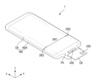
도 1은 일 실시예에 따른 표시 장치의 사시도이고, 도 2는 일 실시예에 따른 표시 장치의 평면도이며, 도 3은 도 2의 Ⅰ-Ⅰ'의 일 예를 보여주는 단면도이고, 도 4는 도 3의 표시 유닛의 일 예를 상세히 보여주는 일 예시도면이다.FIG. 1 is a perspective view of a display device according to one embodiment, FIG. 2 is a plan view of a display device according to one embodiment, FIG. 3 is a cross-sectional view showing an example taken along line I-I' of FIG. 2, and FIG. 4 is an exemplary drawing showing in detail an example of the display unit of FIG. 3.
본 명세서에서, “상부”, “탑”, “상면”은 표시 장치(1)를 기준으로 상부 방향, 즉 z축 방향을 가리키고, “하부”, “바텀”, “하면”은 표시 장치(1)를 기준으로 하부 방향, 즉 y축 방향의 반대 방향을 가리킨다. 또한, “좌”, “우”, “상”, “하”는 표시 장치(1)를 평면에서 바라보았을 때의 방향을 가리킨다. 예를 들어, “좌”는 x축 방향의 반대 방향, “우”는 x축 방향, “상”은 y축 방향, “하”는 y축 방향의 반대 방향을 가리킨다.In this specification, “upper”, “top”, and “surface” refer to the upper direction with respect to the display device (1), that is, the z-axis direction, and “lower”, “bottom”, and “lower” refer to the lower direction with respect to the display device (1), that is, the opposite direction to the y-axis direction. In addition, “left”, “right”, “upper”, and “lower” refer to the direction when the display device (1) is viewed from a plane. For example, “left” refers to the opposite direction to the x-axis direction, “right” refers to the x-axis direction, “upper” refers to the y-axis direction, and “lower” refers to the opposite direction to the y-axis direction.
도 1 내지 도 4를 참조하면, 표시 장치(1)는 동영상이나 정지영상을 표시하는 장치로서, 모바일 폰(mobile phone), 스마트 폰(smart phone), 태블릿 PC(tablet personal computer), 및 스마트 워치(smart watch), 워치 폰(watch phone), 이동 통신 단말기, 전자 수첩, 전자 책, PMP(portable multimedia player), 네비게이션, UMPC(Ultra Mobile PC) 등과 같은 휴대용 전자 기기 뿐만 아니라, 텔레비전, 노트북, 모니터, 광고판, 사물 인터넷(internet of things, IOT) 등의 다양한 제품의 표시 화면으로 사용될 수 있다. 표시 장치(10)는 유기 발광 표시 장치, 액정 표시 장치, 플라즈마 표시 장치, 전계방출 표시 장치, 전기 영동 표시 장치, 전기 습윤 표시 장치, 양자점 발광 표시 장치, 및 마이크로 LED 표시 장치 중 어느 하나일 수 있다. 이하에서는, 표시 장치(1)가 유기 발광 표시 장치인 것을 중심으로 설명하였으나, 본 발명은 이에 제한되지 않는다.Referring to FIGS. 1 to 4, a display device (1) is a device that displays a moving image or a still image, and can be used as a display screen of various products, such as a mobile phone, a smart phone, a tablet personal computer (PC), a smart watch, a watch phone, a mobile communication terminal, an electronic notebook, an electronic book, a PMP (portable multimedia player), a navigation device, an UMPC (Ultra Mobile PC), and the like, as well as a television, a laptop, a monitor, a billboard, and the Internet of Things (IOT). The display device (10) may be any one of an organic light emitting display device, a liquid crystal display device, a plasma display device, a field emission display device, an electrophoretic display device, an electrowetting display device, a quantum dot light emitting display device, and a micro LED display device. Hereinafter, the display device (1) is described mainly as an organic light emitting display device, but the present invention is not limited thereto.
표시 장치(1)는 평면 상 직사각형 형태로 이루어질 수 있다. 예를 들어, 표시 장치(1)는 제1 방향(x축 방향)의 단변과 제2 방향(y축 방향)의 장변을 갖는 직사각형의 평면 형태를 가질 수 있다. 제1 방향(x축 방향)의 단변과 제2 방향(y축 방향)의 장변이 만나는 모서리는 소정의 곡률을 갖도록 둥글게 형성되거나 직각으로 형성될 수 있다. 표시 장치(1)의 평면 형태는 직사각형에 한정되지 않고, 다른 다각형, 원형 또는 타원형으로 형성될 수 있다.The display device (1) may be formed in a rectangular shape on a plane. For example, the display device (1) may have a rectangular shape on a plane having a short side in a first direction (x-axis direction) and a long side in a second direction (y-axis direction). An edge where the short side in the first direction (x-axis direction) and the long side in the second direction (y-axis direction) meet may be formed rounded to have a predetermined curvature or formed at a right angle. The plane shape of the display device (1) is not limited to a rectangle, and may be formed in another polygonal, circular, or oval shape.
표시 장치(1)는 평탄하게 형성된 제1 영역(DR1)과 제1 영역(DR1)의 좌측 및 우측으로부터 각각 연장된 제2 영역(DR2)을 포함할 수 있다. 제2 영역(DR2)은 곡면으로 형성될 수 있고, 제2 영역(DR2)은 일정한 곡률을 갖거나 변화하는 곡률을 가질 수 있다.The display device (1) may include a first region (DR1) formed flatly and a second region (DR2) extending from the left and right sides of the first region (DR1), respectively. The second region (DR2) may be formed as a curved surface, and the second region (DR2) may have a constant curvature or a varying curvature.
도 1 에서는 제2 영역(DR2)이 제1 영역(DR1)의 좌측 및 우측으로 각각에서 연장된 것을 예시하였으나, 이에 한정되지 않는다. 즉, 제2 영역(DR2)은 제1 영역(DR1)의 좌측 및 우측 중 어느 한 측에서만 연장될 수 있다. 또는, 제2 영역(DR2)은 제1 영역(DR1)의 좌측 및 우측뿐만 아니라 상측 및 하측 중 적어도 어느 하나에서도 연장될 수 있다. 이하에서는, 제2 영역(DR2)이 표시 장치(1)의 좌측 및 우측 가장자리에 배치된 것을 중심으로 설명한다.In FIG. 1, the second region (DR2) is exemplified as extending to the left and right sides of the first region (DR1), respectively, but is not limited thereto. That is, the second region (DR2) may extend only to either the left or right side of the first region (DR1). Alternatively, the second region (DR2) may extend not only to the left and right sides of the first region (DR1), but also to at least either the upper or lower sides. Hereinafter, the second region (DR2) will be described mainly with respect to being arranged at the left and right edges of the display device (1).
몇몇 실시예에서 표시 장치(1)는 표시 패널(300), 표시 패널 구동부(400), 회로 보드(CB), 및 터치 제어부(200)를 포함할 수 있다.In some embodiments, the display device (1) may include a display panel (300), a display panel driver (400), a circuit board (CB), and a touch control unit (200).
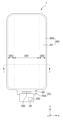
도 2 도 4를 참조하면, 표시 패널(300)은 메인 영역(MA)과 메인 영역(MA)의 일측으로부터 돌출된 돌출 영역(PA)을 포함할 수 있다.Referring to FIG. 2 and FIG. 4, the display panel (300) may include a main area (MA) and a protruding area (PA) protruding from one side of the main area (MA).
메인 영역(MA)은 평탄하게 형성된 제1 영역(DR1)과 제1 영역(DR1)의 좌측 및 우측으로부터 각각 연장된 제2 영역(DR2)을 포함할 수 있으며, 메인 영역(MA)은 화소들이 형성되어 영상을 표시하는 표시 영역(DA)과 표시 영역(DA)의 주변 영역인 비표시 영역(NDA)을 포함할 수 있다.The main area (MA) may include a first area (DR1) formed flatly and a second area (DR2) extending from the left and right sides of the first area (DR1), respectively, and the main area (MA) may include a display area (DA) in which pixels are formed to display an image and a non-display area (NDA) surrounding the display area (DA).
표시 영역(DA)에는 화소들 뿐만 아니라, 화소들에 접속되는 주사선들(310), 데이터선들(320), 및 전원 라인들(PWL)이 배치될 수 있으며, 표시 영역(DA)은 평면부인 제1 영역(DR1)과 제1 영역(DR1)의 좌측 및 우측으로부터 각각 연장된 곡면부인 제2 영역(DR2)에 배치될 수 있다. 이에 따라, 곡면부인 제2 영역(DR2)에서도 표시 패널(300)의 영상이 보일 수 있다.In the display area (DA), not only pixels but also scan lines (310), data lines (320), and power lines (PWL) connected to the pixels can be arranged, and the display area (DA) can be arranged in a first area (DR1) that is a flat portion and a second area (DR2) that is a curved portion extending from the left and right sides of the first area (DR1), respectively. Accordingly, an image of the display panel (300) can be viewed even in the second area (DR2) that is a curved portion.
비표시 영역(NDA)은 표시 영역(DA)의 바깥쪽에서부터 표시 패널(300)의 가장자리까지의 영역으로 정의될 수 있다. 비표시 영역(NDA)에는 주사선들(310)에 주사 신호들을 인가하기 위한 주사 구동부(401), 및 데이터선들(320)과 표시 구동 회로(403)를 연결하는 링크 라인들(LL)들이 배치될 수 있다. 이와 같은, 주사 구동부(401) 및 표시 구동 회로(403)는 표시 패널 구동부(400)를 이룰 수 있다.The non-display area (NDA) may be defined as an area from the outside of the display area (DA) to the edge of the display panel (300). In the non-display area (NDA), a scan driver (401) for applying scan signals to scan lines (310) and link lines (LL) for connecting data lines (320) and a display driver circuit (403) may be arranged. The scan driver (401) and the display driver circuit (403) may form a display panel driver (400).
돌출 영역(PA)은 메인 영역(MA)의 일측으로부터 돌출될 수 있다. 예를 들어, 돌출 영역(PA)은 도 2와 같이 메인 영역(MA)의 하측으로부터 제2 방향(y축 방향)의 반대 방향으로 돌출될 수 있다. 돌출 영역(PA)의 제1 방향(x축 방향)의 길이는 메인 영역(MA)의 제1 방향(x축 방향)의 길이보다 작을 수 있다.The protruding area (PA) may protrude from one side of the main area (MA). For example, the protruding area (PA) may protrude in a direction opposite to the second direction (y-axis direction) from the lower side of the main area (MA), as shown in Fig. 2. The length of the protruding area (PA) in the first direction (x-axis direction) may be smaller than the length of the main area (MA) in the first direction (x-axis direction).
돌출 영역(PA)은 벤딩 영역(BA)과 패드 영역(PDA)을 포함할 수 있다. 이 경우, 패드 영역(PDA)은 벤딩 영역(BA)의 일측에 배치되고, 메인 영역(MA)은 벤딩 영역(BA)의 타측에 배치될 수 있다. 예를 들어, 패드 영역(PDA)은 벤딩 영역(BA)의 하측에 배치되고, 메인 영역(MA)은 벤딩 영역(BA)의 상측에 배치될 수 있다.The protruding area (PA) may include a bending area (BA) and a pad area (PDA). In this case, the pad area (PDA) may be arranged on one side of the bending area (BA), and the main area (MA) may be arranged on the other side of the bending area (BA). For example, the pad area (PDA) may be arranged on the lower side of the bending area (BA), and the main area (MA) may be arranged on the upper side of the bending area (BA).
표시 패널(300)은 구부러지거나, 휘어지거나, 벤딩되거나, 접히거나, 말릴 수 있도록 유연하게 형성될 수 있다. 그러므로, 표시 패널(300)은 벤딩 영역(BA)에서 두께 방향(z축 방향)으로 벤딩될 수 있다. 이 경우, 표시 패널(300)이 벤딩되기 전에 표시 패널(300)의 패드 영역(PDA)의 일면은 상부를 향하고 있으나, 표시 패널(300)이 벤딩된 후에는 표시 패널(300)의 패드 영역(PDA)의 일면은 하부로 향하게 된다. 이로 인해, 패드 영역(PDA)은 메인 영역(MA)의 하부에 배치되어 메인 영역(MA)과 중첩될 수 있다. 다만, 이에 한정되는 것은 아니고, 표시 패널(300)은 벤딩 영역(BA) 없이 구성될 수도 있으며, 이 경우, 표시 패널(300)의 패드 영역(PDA)의 일면은 상부로 향하게 된다.The display panel (300) can be flexibly formed so as to be bent, curved, folded, or rolled. Therefore, the display panel (300) can be bent in the thickness direction (z-axis direction) in the bending area (BA). In this case, before the display panel (300) is bent, one side of the pad area (PDA) of the display panel (300) faces upward, but after the display panel (300) is bent, one side of the pad area (PDA) of the display panel (300) faces downward. Accordingly, the pad area (PDA) can be arranged below the main area (MA) and overlap with the main area (MA). However, the present invention is not limited thereto, and the display panel (300) can be configured without the bending area (BA), in which case, one side of the pad area (PDA) of the display panel (300) faces upward.
표시 패널(300)의 패드 영역(PDA)에는 표시 구동 회로(403) 및 회로 보드(CB)와 전기적으로 연결되는 패드부가 배치될 수 있다.A pad portion electrically connected to a display driving circuit (403) and a circuit board (CB) can be placed in a pad area (PDA) of the display panel (300).
표시 구동 회로(403)는 표시 패널(300)을 구동하기 위한 신호들과 전압들을 출력한다. 예를 들어, 표시 구동 회로(403)는 데이터선들(320)에 데이터 전압들을 공급할 수 있다. 또한, 표시 구동 회로(403)는 전원 라인들(PWL)에 전원 전압을 공급하며, 주사 구동부(401)에 주사 제어 신호들을 공급할 수 있다. 표시 구동 회로(403)는 집적회로(integrated circuit, IC)로 형성되어 COG(chip on glass) 방식, COP(chip on plastic) 방식, 또는 초음파 접합 방식으로 패드 영역(PDA)에서 표시 패널(300) 상에 장착될 수 있으나, 이에 한정되지 않는다. 예를 들어, 표시 구동 회로(403)는 회로 보드(CB) 상에 장착될 수 있다.The display driving circuit (403) outputs signals and voltages for driving the display panel (300). For example, the display driving circuit (403) may supply data voltages to the data lines (320). In addition, the display driving circuit (403) may supply power voltages to the power lines (PWL) and supply scan control signals to the scan driving unit (401). The display driving circuit (403) may be formed as an integrated circuit (IC) and mounted on the display panel (300) in a pad area (PDA) using a COG (chip on glass) method, a COP (chip on plastic) method, or an ultrasonic bonding method, but is not limited thereto. For example, the display driving circuit (403) may be mounted on a circuit board (CB).
패드부는 도 4와 같이 표시 구동 회로(403)에 전기적으로 연결되는 표시 패드부(DP)와 도 5와 같이 터치 센서(TSM)에 배치된 신호선들(9111, 9113, 9115, 9117, 9125, 9127)에 전기적으로 연결되는 터치 패드부들(TP1, TP2)을 포함할 수 있다.The pad portion may include a display pad portion (DP) electrically connected to a display driving circuit (403) as shown in FIG. 4, and touch pad portions (TP1, TP2) electrically connected to signal lines (9111, 9113, 9115, 9117, 9125, 9127) arranged in a touch sensor (TSM) as shown in FIG. 5.
회로 보드(CB)는 이방성 도전 필름(anisotropic conductive film)을 이용하여 패드 영역(PDA) 상에 부착될 수 있다. 이로 인해, 회로 보드(CB)의 리드 라인들은 패드부들(DP, TP1, TP2)과 전기적으로 연결될 수 있다. 회로 보드(CB)는 연성 인쇄 회로 보드(flexible prinited circuit board), 인쇄 회로 보드(printed circuit board) 또는 칩온 필름(chip on film)과 같은 연성 필름(flexible film)일 수 있다.The circuit board (CB) can be attached on the pad area (PDA) using an anisotropic conductive film. As a result, the lead lines of the circuit board (CB) can be electrically connected to the pad portions (DP, TP1, TP2). The circuit board (CB) can be a flexible film such as a flexible printed circuit board, a printed circuit board, or a chip on film.
터치 제어부(200)는 도 5와 같은 센서부(100)와 전기적으로 연결되어 센서부(100)에 구동신호를 공급하고, 센서부(100)로부터 구동신호에 대응하는 감지신호를 수신하여 터치 위치를 검출할 수 있다 터치 제어부(200)는 회로 보드(CB) 상에 배치될 수 있다. 터치 제어부(200)는 집적회로(IC)로 형성되어 회로 보드(CB) 상에 장착될 수 있다. 센서부(100)와 터치 제어부(200)의 구체적인 설명은 도 5 및 도 6과 결부하여 후술한다.The touch control unit (200) is electrically connected to the sensor unit (100) as shown in FIG. 5, supplies a driving signal to the sensor unit (100), and receives a detection signal corresponding to the driving signal from the sensor unit (100) to detect a touch position. The touch control unit (200) may be placed on a circuit board (CB). The touch control unit (200) may be formed as an integrated circuit (IC) and mounted on the circuit board (CB). A specific description of the sensor unit (100) and the touch control unit (200) will be described later in connection with FIG. 5 and FIG. 6.
도 3을 참조하면, 표시 장치(1)는 베이스 기판(330), 베이스 기판(330) 상에 배치된 박막 트랜지스터층(340), 발광 소자층(350), 및 박막 봉지층(110)을 갖는 표시 패널(300)과, 표시 패널(300) 상부에 배치된 터치 센서(TSM)를 포함할 수 있다.Referring to FIG. 3, the display device (1) may include a display panel (300) having a base substrate (330), a thin film transistor layer (340), a light emitting element layer (350), and a thin film encapsulation layer (110) disposed on the base substrate (330), and a touch sensor (TSM) disposed on the upper portion of the display panel (300).
베이스 기판(330)은 유리, 석영, 고분자 수지 등의 절연 물질로 이루어질 수 있다. 고분자 물질의 예로는 폴리에테르술폰(polyethersulphone: PES), 폴리아크릴레이트(polyacrylate: PA), 폴리아릴레이트(polyarylate: PAR), 폴리에테르이미드(polyetherimide: PEI), 폴리에틸렌 나프탈레이트(polyethylene napthalate: PEN), 폴리에틸렌 테레프탈레이드(polyethylene terepthalate: PET), 폴리페닐렌 설파이드(polyphenylene sulfide: PPS), 폴리알릴레이트(polyallylate), 폴리이미드(polyimide: PI), 폴리카보네이트(polycarbonate: PC), 셀룰로오스 트리 아세테이트(cellulose triacetate: CAT), 셀룰로오스 아세테이트 프로피오네이트(cellulose acetate propionate: CAP) 또는 이들의 조합을 들 수 있다. 또는, 베이스 기판(330)은 금속 재질의 물질을 포함할 수도 있다.The base substrate (330) may be made of an insulating material such as glass, quartz, or a polymer resin. Examples of the polymer material may include polyethersulphone (PES), polyacrylate (PA), polyarylate (PAR), polyetherimide (PEI), polyethylene napthalate (PEN), polyethylene terepthalate (PET), polyphenylene sulfide (PPS), polyallylate, polyimide (PI), polycarbonate (PC), cellulose triacetate (CAT), cellulose acetate propionate (CAP), or a combination thereof. Alternatively, the base substrate (330) may include a metal material.
베이스 기판(330)은 리지드(rigid) 기판이거나 벤딩(bending), 폴딩(folding), 롤링(rolling) 등이 가능한 플렉서블(flexible) 기판일 수 있다. 기판(SUB)이 플렉서블 기판인 경우, 폴리이미드(PI)로 형성될 수 있지만, 이에 한정되는 것은 아니다.The base substrate (330) may be a rigid substrate or a flexible substrate capable of bending, folding, rolling, etc. If the substrate (SUB) is a flexible substrate, it may be formed of polyimide (PI), but is not limited thereto.
박막 트랜지스터층(340)은 베이스 기판(330) 상에 배치될 수 있다. 박막 트랜지스터층(340)에는 화소(P)들 각각의 박막 트랜지스터들뿐만 아니라, 주사선들(310), 데이터선들(320), 전원 라인들(PWL), 주사 제어 라인들(SCL), 및 표시 패드부(DP)와 데이터선들(320)을 연결하는 링크 라인들(LL) 등이 형성될 수 있다. 박막 트랜지스터들 각각은 게이트 전극, 반도체층, 소스 전극, 및 드레인 전극을 포함할 수 있다. 주사 구동부(401)가 도 4와 같이 표시 패널(300)의 비표시 영역(NDA)에 형성되는 경우, 주사 구동부(401)는 박막 트랜지스터들을 포함할 수 있다.A thin film transistor layer (340) may be disposed on a base substrate (330). In addition to thin film transistors of each pixel (P), scan lines (310), data lines (320), power lines (PWL), scan control lines (SCL), and link lines (LL) connecting a display pad portion (DP) and the data lines (320) may be formed on the thin film transistor layer (340). Each of the thin film transistors may include a gate electrode, a semiconductor layer, a source electrode, and a drain electrode. When the scan driver (401) is formed in a non-display area (NDA) of the display panel (300) as shown in FIG. 4, the scan driver (401) may include thin film transistors.
박막 트랜지스터층(340)은 표시 영역(DA)과 비표시 영역(NDA)에 배치될 수 있다. 구체적으로, 박막 트랜지스터층(340)의 화소(P)들 각각의 박막 트랜지스터들, 주사선들(310), 데이터선들(320) 및 전원 라인들(PWL)들은 표시 영역(DA)의 제1 영역(DR1) 및 제2 영역(DR2)에 배치될 수 있다. 박막 트랜지스터층(TFTL)의 주사 제어 라인들(SCL)과 링크 라인들(LL)은 비표시 영역(NDA)에 배치될 수 있다.The thin film transistor layer (340) may be arranged in the display area (DA) and the non-display area (NDA). Specifically, the thin film transistors, scan lines (310), data lines (320), and power lines (PWL) of each of the pixels (P) of the thin film transistor layer (340) may be arranged in the first area (DR1) and the second area (DR2) of the display area (DA). The scan control lines (SCL) and link lines (LL) of the thin film transistor layer (TFTL) may be arranged in the non-display area (NDA).
박막 트랜지스터층(340) 상에는 발광 소자층(350)이 배치될 수 있다. 발광 소자층(350)은 제1 전극, 발광층, 및 제2 전극을 포함하는 화소(P)들과 화소(P)들을 정의하는 화소 정의막을 포함할 수 있다. 발광층은 유기 물질을 포함하는 유기 발광층일 수 있다. 박막 트랜지스터층(340)의 박막 트랜지스터를 통해 제1 전극에 소정의 전압이 인가되고, 제2 전극에 캐소드 전압이 인가되면 정공과 전자가 각각 정공 수송층과 전자 수송층을 통해 유기 발광층으로 이동되며, 유기 발광층에서 서로 결합하여 발광하게 된다. 발광 소자층(350)의 화소들은 표시 영역(DA)에 배치될 수 있다.A light-emitting element layer (350) may be arranged on the thin film transistor layer (340). The light-emitting element layer (350) may include pixels (P) including a first electrode, a light-emitting layer, and a second electrode, and a pixel definition film defining the pixels (P). The light-emitting layer may be an organic light-emitting layer including an organic material. When a predetermined voltage is applied to the first electrode and a cathode voltage is applied to the second electrode through the thin film transistor of the thin film transistor layer (340), holes and electrons move to the organic light-emitting layer through the hole transport layer and the electron transport layer, respectively, and combine with each other in the organic light-emitting layer to emit light. The pixels of the light-emitting element layer (350) may be arranged in the display area (DA).
발광 소자층(350) 상에는 박막 봉지층(110)이 배치될 수 있다. 박막 봉지층(110)은 발광 소자층(350)에 산소 또는 수분이 침투되는 것을 방지하는 역할을 한다. A thin film encapsulation layer (110) may be placed on the light emitting element layer (350). The thin film encapsulation layer (110) serves to prevent oxygen or moisture from penetrating into the light emitting element layer (350).
박막 봉지층(110)은 표시 영역(DA)과 비표시 영역(NDA) 모두에 배치될 수 있다. 구체적으로, 박막 봉지층(110)은 표시 영역(DA)과 비표시 영역(NDA)의 발광 소자층(350)을 덮으며, 비표시 영역(NDA)의 박막 트랜지스터층(340)을 덮도록 배치될 수 있다.The thin film encapsulation layer (110) can be arranged in both the display area (DA) and the non-display area (NDA). Specifically, the thin film encapsulation layer (110) can be arranged to cover the light emitting element layer (350) of the display area (DA) and the non-display area (NDA), and to cover the thin film transistor layer (340) of the non-display area (NDA).
박막 봉지층(110) 상에는 터치 센서(TSM)가 배치될 수 있다. 터치 센서(TSM)가 박막 봉지층(110) 상에 바로 배치됨으로써, 터치 센서(TSM)를 포함하는 별도의 터치 패널이 박막 봉지층(110) 상에 부착되는 경우보다 표시 장치(1)의 두께를 줄일 수 있는 장점이 있다. A touch sensor (TSM) may be placed on the thin film encapsulation layer (110). Since the touch sensor (TSM) is placed directly on the thin film encapsulation layer (110), there is an advantage in that the thickness of the display device (1) can be reduced compared to when a separate touch panel including the touch sensor (TSM) is attached on the thin film encapsulation layer (110).
터치 센서(TSM)의 센서부(100)는 도 5와 같이 표시 영역(DA)에 중첩하는 감지 영역(TSA)과 비표시 영역(NDA)에 중첩하는 주변 영역(NSA)을 포함할 수 있다. 감지 영역(SA)은 평면부인 제1 영역(DR1)과, 제1 영역(DR1)의 좌측 및 우측으로부터 각각 연장된 곡면부인 제2 영역(DR2)을 포함할 수 있다. 터치 센서(TSM)의 신호선들(9111, 9113, 9115, 9117, 9125, 9127)은 주변 영역(NSA)에 배치될 수 있다.The sensor unit (100) of the touch sensor (TSM) may include a detection area (TSA) overlapping a display area (DA) and a peripheral area (NSA) overlapping a non-display area (NDA), as shown in FIG. 5. The detection area (SA) may include a first area (DR1) that is a flat area and a second area (DR2) that is a curved area extending from the left and right sides of the first area (DR1), respectively. Signal lines (9111, 9113, 9115, 9117, 9125, 9127) of the touch sensor (TSM) may be arranged in the peripheral area (NSA).
도시되지는 않았지만, 터치 센서(TSM) 상에는 커버 윈도우가 추가로 배치될 수 있으며, 이 경우, 커버 윈도우는 OCA(optically clear adhesive) 필름과 같은 투명 접착 부재에 의해 부착될 수 있다.Although not shown, a cover window may additionally be placed on the touch sensor (TSM), in which case the cover window may be attached by a transparent adhesive material such as an optically clear adhesive (OCA) film.
도 5는 도 3의 터치 센서를 도시한 도면으로서, 터치 센서 중 센서부의 평면도 및 센서부와 제어부 간의 연결관계를 도시한 도면이고, 도 6은 도 3의 터치 센서의 블록도를 나타낸 도면이며, 도 7은 도 5의 Q1 부분을 확대한 평면도이고, 도 8은 일 실시예에 따른 표시 장치에 있어서, 스트레인 게이지와 온도 보상 패턴의 배치를 설명하기 위하여 참조되는 도면이며, 도 9는 도 7에 도시된 센서부 중 제1 층의 구조를 도시한 도면이고, 도 10은 도 9의 Q2 부분을 확대한 평면도이며, 도 11은 도 10에 도시된 저항선의 다른 실시예를 도시한 도면이고, 도 12는 도 10에 도시된 저항선의 다른 실시예를 도시한 도면이며, 도 13은 도 10에 도시된 저항선의 다른 실시예를 도시한 도면이고, 도 14는 도 9의 Q3 부분을 확대한 평면도이며, 도 15는 도 7에 도시된 센서부 중 제2 층의 구조를 도시한 도면이고, 도 16은 도 7의 X1-X1'를 따라 절단한 단면도이며, 도 17은 도 7의 X2-X2' 및 X3-X3'을 따라 절단한 단면도이다.FIG. 5 is a drawing illustrating the touch sensor of FIG. 3, and is a drawing illustrating a plan view of a sensor portion of the touch sensor and a connection relationship between the sensor portion and the control portion, FIG. 6 is a drawing illustrating a block diagram of the touch sensor of FIG. 3, FIG. 7 is a plan view illustrating an enlarged portion of Q1 of FIG. 5, FIG. 8 is a drawing referenced to explain the arrangement of a strain gauge and a temperature compensation pattern in a display device according to one embodiment, FIG. 9 is a drawing illustrating the structure of a first layer of the sensor portion illustrated in FIG. 7, FIG. 10 is a plan view illustrating an enlarged portion of Q2 of FIG. 9, FIG. 11 is a drawing illustrating another embodiment of the resistance line illustrated in FIG. 10, FIG. 12 is a drawing illustrating another embodiment of the resistance line illustrated in FIG. 10, FIG. 13 is a drawing illustrating another embodiment of the resistance line illustrated in FIG. 10, FIG. 14 is a plan view illustrating an enlarged portion of Q3 of FIG. 9, and FIG. 15 is a drawing illustrating the structure of a second layer of the sensor portion illustrated in FIG. 7. The drawings are schematic, and FIG. 16 is a cross-sectional view taken along line X1-X1' of FIG. 7, and FIG. 17 is a cross-sectional view taken along line X2-X2' and X3-X3' of FIG. 7.
도 5 내지 도 16 참조하면, 센서부(100)는 베이스층(110), 제1 전극부(120), 제2 전극부(130), 스트레인 게이지(150) 및 온도 보상 패턴(160)을 포함하며, 더미전극(190)을 더 포함할 수 있다.Referring to FIGS. 5 to 16, the sensor unit (100) includes a base layer (110), a first electrode unit (120), a second electrode unit (130), a strain gauge (150), and a temperature compensation pattern (160), and may further include a dummy electrode (190).
베이스층(110)은 평면부인 제1 영역(DR1)과, 제1 영역(DR1)의 좌측 및 우측으로부터 각각 연장된 곡면부인 제2 영역(DR2)을 포함하는 감지 영역(SA) 및 주변 영역(NSA)을 포함할 수 있다. 베이스층(110)은 센서부(100)의 기재가 되는 층으로서 몇몇 실시예에서 베이스층(110)은 표시 패널(300)을 구성하는 층 중 하나일 수도 있다. 예컨대, 센서부(100)와 표시 패널(300)이 일체로 구현되는 실시예에서, 베이스층(110)은 표시 패널(300)을 구성하는 적어도 하나의 층일 수 있다. 예시적으로 베이스층(110)은 표시 패널(300)의 박막 봉지층(Thin Film Encapsulation: TFE)을 포함할 수 있다. 또는 실시예에서 따라 베이스층(110)은 경성 기판 또는 가요성 기판일 수 있다. 예컨대, 베이스층(110)은 유리 또는 강화 유리로 구성된 경성 기판, 또는 유연한 플라스틱 재질의 박막 필름으로 구성된 가요성 기판일 수도 있다. 이하에서는 베이스층(110)이 표시 패널(300)을 구성하는 적어도 하나의 층, 예컨대 박막 봉지층을 포함하는 층으로 이루어진 경우를 예시로 설명한다.The base layer (110) may include a sensing area (SA) and a peripheral area (NSA) including a first area (DR1) which is a flat portion and a second area (DR2) which is a curved portion extending from the left and right sides of the first area (DR1), respectively. The base layer (110) is a layer that serves as a substrate for the sensor unit (100), and in some embodiments, the base layer (110) may be one of the layers constituting the display panel (300). For example, in an embodiment in which the sensor unit (100) and the display panel (300) are implemented integrally, the base layer (110) may be at least one layer constituting the display panel (300). For example, the base layer (110) may include a thin film encapsulation (TFE) layer of the display panel (300). Or, depending on the embodiment, the base layer (110) may be a rigid substrate or a flexible substrate. For example, the base layer (110) may be a rigid substrate made of glass or tempered glass, or a flexible substrate made of a thin film made of a flexible plastic material. Hereinafter, a case in which the base layer (110) is made of at least one layer forming the display panel (300), for example, a layer including a thin film encapsulation layer, will be described as an example.
베이스층(110)의 감지 영역(SA) 상에는 제1 전극부(120), 제1 전극부(120)와 절연된 제2 전극부(130), 제1 전극부(120) 및 제2 전극부(130)와 각각 절연된 스트레인 게이지(150) 및 온도 보상 패턴(160)이 위치할 수 있다.On the sensing area (SA) of the base layer (110), a first electrode part (120), a second electrode part (130) insulated from the first electrode part (120), a strain gauge (150) and a temperature compensation pattern (160) insulated from the first electrode part (120) and the second electrode part (130), respectively, may be positioned.
제1 전극부(120)는 평면부인 제1 영역(DR1)과, 제1 영역(DR1)의 좌측 및 우측으로부터 각각 연장된 곡면부인 제2 영역(DR2)에 위치할 수 있다. 제1 전극부(120)는 제1 방향(x축 방향)을 따라 연장되고 제2 방향(y축 방향)을 따라 서로 이격 배치될 수 있다. 제2 방향(y축 방향)을 따라 서로 이격 배치된 제1 전극부(120)는 각각 전극행을 구성할 수 있다. 도 5에서는 예시적으로 제1 전극부(120)가 제2 방향(y축 방향)을 따라 8개 배치되고 각 제1 전극부(120)가 제2 방향(y축 방향)을 따라 순차적으로 제1 전극행(RE1), 제2 전극행(RE2), 제3 전극행(RE3), 제4 전극행(RE4), 제5 전극행(RE5), 제6 전극행(RE6), 제7 전극행(RE7) 및 제8 전극행(RE8)을 이루는 것으로 도시하였다. 다만 이에 한정되는 것은 아니며, 제1 전극부(120)의 개수는 다양하게 변경될 수 있다.The first electrode portion (120) may be positioned in a first region (DR1) which is a flat portion, and a second region (DR2) which is a curved portion extending from the left and right sides of the first region (DR1), respectively. The first electrode portions (120) may extend along the first direction (x-axis direction) and may be spaced apart from each other along the second direction (y-axis direction). The first electrode portions (120) spaced apart from each other along the second direction (y-axis direction) may each form an electrode row. In Fig. 5, eight first electrode parts (120) are arranged along the second direction (y-axis direction) as an example, and each first electrode part (120) sequentially forms a first electrode row (RE1), a second electrode row (RE2), a third electrode row (RE3), a fourth electrode row (RE4), a fifth electrode row (RE5), a sixth electrode row (RE6), a seventh electrode row (RE7), and an eighth electrode row (RE8) along the second direction (y-axis direction). However, this is not limited thereto, and the number of first electrode parts (120) may be changed in various ways.
제1 전극부(120)는 제1 방향(x축 방향)을 따라 배열된 복수의 제1 터치전극(121) 및 제1 방향(x축 방향)을 따라 서로 이웃하는 제1 터치전극(121)을 서로 전기적으로 연결하는 제1 연결부(123)를 포함할 수 있다. 이하 실시예들을 설명함에 있어서, "연결"이라 함은 물리적 및/또는 전기적인 측면에서의 "연결"을 포괄적으로 의미할 수 있다.The first electrode portion (120) may include a plurality of first touch electrodes (121) arranged along a first direction (x-axis direction) and a first connection portion (123) electrically connecting the first touch electrodes (121) adjacent to each other along the first direction (x-axis direction). In describing the embodiments below, “connection” may comprehensively mean “connection” in a physical and/or electrical aspect.
몇몇 실시예에서 제1 터치전극(121)은 제1 층(L1)에 위치할 수 있다. 제1 터치전극(121)의 평면 형상은 마름모 형상일 수 있으나, 이에 한정되는 것은 아니며 제1 터치전극(121)의 형상은 삼각형, 마름모 이외의 사각형, 오각형, 원형, 바(bar)형 등 다양한 형상으로 변형될 수도 있다.In some embodiments, the first touch electrode (121) may be located in the first layer (L1). The planar shape of the first touch electrode (121) may be a rhombus shape, but is not limited thereto, and the shape of the first touch electrode (121) may be transformed into various shapes such as a triangle, a square other than a rhombus, a pentagon, a circle, a bar shape, etc.
제1 터치전극(121)은 도전성 물질을 포함할 수 있다. 예시적으로 상기 도전성 물질은 금속이나 이들의 합금을 포함할 수 있다. 상기 금속으로는 금(Au), 은(Ag), 알루미늄(Al), 몰리브덴(Mo), 크롬(Cr), 타이타늄(Ti), 니켈(Ni), 네오디뮴(Nd), 구리(Cu), 백금(Pt) 등을 들 수 있다. 또한, 제1 터치전극(121)은 투명 도전성 물질로 이루어질 수도 있다. 상기 투명 도전성 물질로는 은나노와이어(AgNW), ITO(Indium Tin Oxide), IZO(Indium Zinc Oxide), AZO(Antimony Zinc Oxide), ITZO(Indium Tin Zinc Oxide), ZnO(Zinc Oxide), 및 SnO2(Tin Oxide), 카본나노튜브(Carbon Nano Tube), 그래핀 (graphene) 등을 들 수 있다. The first touch electrode (121) may include a conductive material. For example, the conductive material may include a metal or an alloy thereof. Examples of the metal include gold (Au), silver (Ag), aluminum (Al), molybdenum (Mo), chromium (Cr), titanium (Ti), nickel (Ni), neodymium (Nd), copper (Cu), platinum (Pt), and the like. In addition, the first touch electrode (121) may be formed of a transparent conductive material. Examples of the transparent conductive material include silver nanowire (AgNW), indium tin oxide (ITO), indium zinc oxide (IZO), antimony zinc oxide (AZO), indium tin zinc oxide (ITZO), zinc oxide (ZnO), tin oxide (SnO2), carbon nanotubes (Carbon Nano Tubes), graphene, and the like.
몇몇 실시예에서 제1 터치전극(121)은 단층구조로 이루어지거나, 또는 다층구조로 이루어질 수도 있다. 제1 터치전극(121)이 다층구조로 이루어지는 경우, 제1 터치전극(121)은 다층의 금속층들을 포함할 수 있다. 예시적으로 제1 터치전극(121)은 티타늄/알루미늄/티타늄의 3층 구조를 가질 수도 있다. In some embodiments, the first touch electrode (121) may be formed of a single-layer structure or may be formed of a multi-layer structure. When the first touch electrode (121) is formed of a multi-layer structure, the first touch electrode (121) may include multiple metal layers. For example, the first touch electrode (121) may have a three-layer structure of titanium/aluminum/titanium.
몇몇 실시예에서 제1 터치전극(121)은 사용자에게 시인되는 것을 방지하기 위해 메쉬(mesh) 구조로 이루어질 수 있다. 제1 터치전극(121)이 메쉬 구조로 이루어지는 경우, 제1 터치전극(121)은 표시 패널(300)의 발광 영역과 비중첩하도록 배치될 수 있다. 바꾸어 말하면, 메쉬 구조의 제1 터치전극(121)에는 발광 영역과 중첩하는 메쉬홀이 정의될 수 있다.In some embodiments, the first touch electrode (121) may be formed in a mesh structure to prevent it from being recognized by a user. When the first touch electrode (121) is formed in a mesh structure, the first touch electrode (121) may be positioned so as not to overlap with the light-emitting area of the display panel (300). In other words, a mesh hole that overlaps with the light-emitting area may be defined in the first touch electrode (121) of the mesh structure.
몇몇 실시예에서 제2 방향(y축 방향)을 따라 이격된 제1 터치전극(121)은 전극열을 이룰 수 있다. 도 5에서는 예시적으로 하나의 열에 제1 터치전극(121)이 8개 배치되고 제2 방향(y축 방향)을 따라 배치된 제1 터치전극(121)이 제1 전극열(CE1), 제2 전극열(CE2), 제3 전극열(CE3), 제4 전극열(CE4), 제5 전극열(CE5), 제6 전극열(CE6), 제7 전극열(CE7) 및 제8 전극열(CE8)을 이루는 것으로 도시하였다. 다만 이에 한정되는 것은 아니며, 제1 터치전극(121)이 이루는 전극열의 개수는 다양하게 변경될 수 있다.In some embodiments, the first touch electrodes (121) spaced apart along the second direction (y-axis direction) may form an electrode row. As an example, FIG. 5 illustrates that eight first touch electrodes (121) are arranged in one row, and the first touch electrodes (121) arranged along the second direction (y-axis direction) form a first electrode row (CE1), a second electrode row (CE2), a third electrode row (CE3), a fourth electrode row (CE4), a fifth electrode row (CE5), a sixth electrode row (CE6), a seventh electrode row (CE7), and an eighth electrode row (CE8). However, the present invention is not limited thereto, and the number of electrode rows formed by the first touch electrodes (121) may be variously changed.
제1 터치전극(121)의 제3 전극열(CE3), 제4 전극열(CE4), 제5 전극열(CE5) 및 제6 전극열(CD6)은 평면부인 제1 영역(DR1)에 배치되고, 제1 전극열(CE1), 제2 전극열(CE2), 제7 전극열(CE7) 및 제8 전극열(CE8)은 곡면부인 제2 영역(DR2)에 배치될 수 있다. 예를 들어, 제1 전극열(CE1) 및 제2 전극열(CE2)은 제1 영역(DR1)에서 제1 방향(x축 방향)으로 연장된 제2 영역(DR2)에 배치될 수 있고, 제7 전극열(CE7) 및 제8 전극열(CE8)은 제1 영역(DR1)에서 제1 방향(x축 방향)의 반대 방향으로 연장된 제2 영역(DR2)에 배치될 수 있다. 다만, 이에 한정되는 것은 아니고, 제1 영역(DR1) 및 제2 영역(DR2)에 배치되는 제1 터치전극(121)의 전극열(CE1, CE2, CE3, CE4, CE5, CE6, CE7, CE8)들의 개수는 곡면부인 제2 영역(DR2)의 크기 및 기능에 따라 다양하게 변형될 수 있다.The third electrode row (CE3), the fourth electrode row (CE4), the fifth electrode row (CE5), and the sixth electrode row (CD6) of the first touch electrode (121) may be arranged in a first region (DR1) which is a flat portion, and the first electrode row (CE1), the second electrode row (CE2), the seventh electrode row (CE7), and the eighth electrode row (CE8) may be arranged in a second region (DR2) which is a curved portion. For example, the first electrode row (CE1) and the second electrode row (CE2) may be arranged in a second region (DR2) which extends in a first direction (x-axis direction) from the first region (DR1), and the seventh electrode row (CE7) and the eighth electrode row (CE8) may be arranged in a second region (DR2) which extends in a direction opposite to the first direction (x-axis direction) from the first region (DR1). However, it is not limited thereto, and the number of electrode rows (CE1, CE2, CE3, CE4, CE5, CE6, CE7, CE8) of the first touch electrode (121) arranged in the first region (DR1) and the second region (DR2) may be variously modified depending on the size and function of the second region (DR2), which is a curved portion.
제1 터치전극(121)은 제1 개구부(OP1)를 포함할 수 있다. 예컨대, 제1 터치전극(121) 각각은 적어도 중앙 부분이 개구되어 제1 터치전극(121) 아래에 위치하는 층을 노출할 수 있다. 예시적으로 제1 터치전극(121) 아래에 절연층(IL)이 위치하는 경우, 절연층(IL)의 일부는 제1 개구부(OP1)를 통해 노출될 수 있다.The first touch electrode (121) may include a first opening (OP1). For example, each of the first touch electrodes (121) may have at least a central portion opened to expose a layer positioned beneath the first touch electrode (121). For example, when an insulating layer (IL) is positioned beneath the first touch electrode (121), a portion of the insulating layer (IL) may be exposed through the first opening (OP1).
제1 연결부(123)는 제1 방향(x축 방향)을 따라 이웃하는 제1 터치전극(121)을 서로 전기적으로 연결할 수 있으며, 제1 터치전극(121)과 접촉할 수 있다. 몇몇 실시예에서 제1 연결부(123)는 브리지(bridge) 형태의 연결 부로 구성될 수 있다. 몇몇 실시예에서 제1 연결부(123)는 제1 터치전극(121)이 위치하는 제1 층(L1)과 다른 제2 층(L2)에 위치할 수 있다.The first connecting portion (123) can electrically connect neighboring first touch electrodes (121) along the first direction (x-axis direction) and can come into contact with the first touch electrode (121). In some embodiments, the first connecting portion (123) can be configured as a bridge-shaped connecting portion. In some embodiments, the first connecting portion (123) can be located in a second layer (L2) different from the first layer (L1) where the first touch electrode (121) is located.
몇몇 실시예에서 제1 터치전극(121)과 제1 연결부(123) 사이에는 절연층(IL)이 위치할 수 있다. 몇몇 실시예에서 제2 층(L2)에 위치하는 제1 연결부(123)는 베이스층(110) 상에 위치하고 절연층(IL)은 제1 연결부(123) 상에 위치하고, 제1 층(L1)에 위치하는 제1 터치전극(121)은 절연층(IL) 상에 위치할 수 있다. 그리고 제1 연결부(123)와 제1 터치전극(121)은 절연층(IL)에 형성된 제1 컨택홀(CH1)을 통해 서로 연결되고 서로 직접 접촉할 수 있다. In some embodiments, an insulating layer (IL) may be positioned between the first touch electrode (121) and the first connection portion (123). In some embodiments, the first connection portion (123) positioned in the second layer (L2) may be positioned on the base layer (110), the insulating layer (IL) may be positioned on the first connection portion (123), and the first touch electrode (121) positioned in the first layer (L1) may be positioned on the insulating layer (IL). In addition, the first connection portion (123) and the first touch electrode (121) may be connected to each other and may directly contact each other through a first contact hole (CH1) formed in the insulating layer (IL).
절연층(IL)은 절연 물질을 포함할 수 있다. 몇몇 실시예에서 상기 절연물질은 무기 절연물질 또는 유기 절연물질일 수 있다. 상기 무기 절연물질은 알루미늄 옥사이드, 티타늄 옥사이드, 실리콘 옥사이드 실리콘옥시나이트라이드, 지르코늄옥사이드, 및 하프늄 옥사이드 중 적어도 하나를 포함할 수 있다. 상기 유기 절연물질은 아크릴계 수지, 메타크릴계 수지, 폴리이소프렌, 비닐계 수지, 에폭시계 수지, 우레탄계 수지, 셀룰로오스계 수지, 실록산계 수지, 폴리이미드계 수지, 폴리아미드계 수지 및 페릴렌계 수지 중 적어도 어느 하나를 포함할 수 있다.The insulating layer (IL) may include an insulating material. In some embodiments, the insulating material may be an inorganic insulating material or an organic insulating material. The inorganic insulating material may include at least one of aluminum oxide, titanium oxide, silicon oxide, silicon oxynitride, zirconium oxide, and hafnium oxide. The organic insulating material may include at least one of an acrylic resin, a methacrylic resin, a polyisoprene, a vinyl resin, an epoxy resin, a urethane resin, a cellulose resin, a siloxane resin, a polyimide resin, a polyamide resin, and a perylene resin.
제1 연결부(123)는 도전성 물질을 포함할 수 있다. 몇몇 실시예에서 제1 연결부(123)는 제1 터치전극(121)과 동일한 물질을 포함하거나, 제1 터치전극(121)의 구성 물질로 예시된 물질에서 선택된 하나 이상의 물질을 포함할 수도 있다. 몇몇 실시예에서 제1 연결부(123)는 단층구조로 이루어질 수 있으며, 다층구조로 이루어질 수 있다. 예시적으로 제1 연결부(123)는 티타늄/알루미늄/티타늄의 3층 구조를 가질 수도 있다. 다만 이에 한정되는 것은 아니며, 제1 연결부(123)는 제1 터치전극(121)과 다른 물질로 이루어질 수도 있다.The first connecting portion (123) may include a conductive material. In some embodiments, the first connecting portion (123) may include the same material as the first touch electrode (121), or may include one or more materials selected from the materials exemplified as the constituent materials of the first touch electrode (121). In some embodiments, the first connecting portion (123) may be formed of a single-layer structure or a multi-layer structure. For example, the first connecting portion (123) may have a three-layer structure of titanium/aluminum/titanium. However, the present invention is not limited thereto, and the first connecting portion (123) may be formed of a different material from the first touch electrode (121).
도면에는 제1 방향(x축 방향)을 따라 이웃하는 제1 터치전극(121) 사이에 제1 연결부(123)가 하나 배치된 것으로 도시되어 있으나, 제1 연결부(123)의 개수는 다양하게 변경될 수 있다. 예를 들어, 제1 방향(x축 방향)을 따라 이웃하는 두개의 제1 터치전극(121) 사이에는 제1 연결부(123)가 두개 이상 배치될 수도 있다.Although the drawing shows that one first connecting portion (123) is arranged between neighboring first touch electrodes (121) along the first direction (x-axis direction), the number of first connecting portions (123) may vary. For example, two or more first connecting portions (123) may be arranged between two neighboring first touch electrodes (121) along the first direction (x-axis direction).
제1 전극부(120)는 평면부인 제1 영역(DR1)과, 제1 영역(DR1)의 좌측 및 우측으로부터 각각 연장된 곡면부인 제2 영역(DR2)에 위치할 수 있다. 제2 전극부(130)는 제2 방향(y축 방향)을 따라 연장되고 제1 방향(x축 방향)을 따라 서로 이격 배치될 수 있다. 제1 방향(x축 방향)을 따라 서로 이격 배치된 제2 전극부(130)는 각각 열을 구성할 수 있다. 도 7에서는 예시적으로 제2 전극부(130)가 제1 방향(x축 방향)을 따라 7개 배치되고 각 제2 전극부(130)가 제1 방향(x축 방향)의 반대방향을 따라 순차적으로 제1 열(CO1), 제2 열(CO2), 제3 열(CO3), 제4 열(CO4), 제5 열(CO5), 제6 열(CO6) 및 제7 열(CO7)을 이루는 것으로 도시하였다. 다만 이에 한정되는 것은 아니며, 제2 전극부(130)의 개수는 다양하게 변경될 수 있다.The first electrode portion (120) may be positioned in a first region (DR1) which is a flat portion, and a second region (DR2) which is a curved portion extending from the left and right sides of the first region (DR1), respectively. The second electrode portions (130) may extend along the second direction (y-axis direction) and be spaced apart from each other along the first direction (x-axis direction). The second electrode portions (130) spaced apart from each other along the first direction (x-axis direction) may each form a row. As an example, FIG. 7 illustrates that seven second electrode portions (130) are arranged along the first direction (x-axis direction) and that each second electrode portion (130) sequentially forms a first row (CO1), a second row (CO2), a third row (CO3), a fourth row (CO4), a fifth row (CO5), a sixth row (CO6), and a seventh row (CO7) along the opposite direction to the first direction (x-axis direction). However, it is not limited to this, and the number of second electrode parts (130) can be changed in various ways.
제2 전극부(130)는 제2 방향(y축 방향)을 따라 배열된 복수의 제2 터치전극(131) 및 제2 방향(y축 방향)을 따라 서로 이웃하는 제2 터치전극(131)을 서로 전기적으로 연결하는 제2 연결부(133)를 포함할 수 있다. The second electrode portion (130) may include a plurality of second touch electrodes (131) arranged along the second direction (y-axis direction) and a second connecting portion (133) electrically connecting the second touch electrodes (131) adjacent to each other along the second direction (y-axis direction).
복수의 제2 터치전극(131)은 제2 방향(y축 방향)을 따라 서로 전기적으로 연결될 수 있다. 또한 제2 터치전극(131)은 제1 방향(x축 방향)을 따라 서로 이격될 수 있다. A plurality of second touch electrodes (131) can be electrically connected to each other along the second direction (y-axis direction). In addition, the second touch electrodes (131) can be spaced apart from each other along the first direction (x-axis direction).
몇몇 실시예에서 제1 방향(x축 방향)을 따라 이격된 제2 터치전극(131)은 행을 이룰 수 있다. 도 7에서는 예시적으로 하나의 열에 제2 터치전극(131)이 8개 배치되고 제1 방향(x축 방향)을 따라 배치된 제2 터치전극(131)이 제1 행(RO1), 제2 행(RO2), 제3 행(RO3), 제4 행(RO4), 제5 행(RO5), 제6 행(RO6), 제7 행(RO7) 및 제8 행(RO8)을 이루는 것으로 도시하였다. 다만 이에 한정되는 것은 아니며, 제2 터치전극(131)이 이루는 행의 개수는 다양하게 변경될 수 있다.In some embodiments, the second touch electrodes (131) spaced apart along the first direction (x-axis direction) may form rows. As an example, FIG. 7 illustrates that eight second touch electrodes (131) are arranged in one column, and the second touch electrodes (131) arranged along the first direction (x-axis direction) form a first row (RO1), a second row (RO2), a third row (RO3), a fourth row (RO4), a fifth row (RO5), a sixth row (RO6), a seventh row (RO7), and an eighth row (RO8). However, the present invention is not limited thereto, and the number of rows formed by the second touch electrodes (131) may be variously changed.
몇몇 실시예에서 제2 터치전극(131)이 이루는 행은 제1 전극부(120)가 이루는 두개의 전극행 사이에 위치할 수 있다. 예시적으로 제1 행(RO1)은 제1 전극행(RE1)과 제2 전극행(RE2) 사이에 위치할 수 있으며, 제2 행(RO2)은 제2 전극행(RE2)과 제3 전극행(RE3) 사이에 위치할 수 있다. 즉, 제2 터치전극(131)이 이루는 행과 제1 전극부(120)가 이루는 전극행은 제2 방향(y축 방향)을 따라 반복적으로 배치될 수 있다.In some embodiments, the row formed by the second touch electrode (131) may be positioned between two electrode rows formed by the first electrode portion (120). For example, the first row (RO1) may be positioned between the first electrode row (RE1) and the second electrode row (RE2), and the second row (RO2) may be positioned between the second electrode row (RE2) and the third electrode row (RE3). That is, the row formed by the second touch electrode (131) and the electrode row formed by the first electrode portion (120) may be repeatedly arranged along the second direction (y-axis direction).
제2 터치전극(131)의 제3 열(CO3), 제4 열(CO4) 및 제5 열(CO5)은 평면부인 제1 영역(DR1)에 배치되고, 제1 열(CO1) 및 제7 열(CO7은 곡면부인 제2 영역(DR2)에 배치되며, 제2 열(CO2) 및 제6 열(CO6)은 제1 영역(DR1)과 제2 영역(DR2)의 각각의 경계에 배치될 수 있다. 예를 들어, 제1 열(CO1)은 제1 영역(DR1)에서 제1 방향(x축 방향)으로 연장된 제2 영역(DR2) 배치될 수 있고, 제7 열(CO7)은 제1 영역(DR1)에서 제1 방향(x축 방향)의 반대 방향으로 연장된 제2 영역(DR2)에 배치되고, 제2 열(CO2)은 제1 영역(DR1)과 제1 영역(DR1)에서 제1 방향(x축 방향)으로 연장된 제2 영역(DR2)의 경계에 걸쳐 배치되고, 제6 열(CO6)은 제1 영역(DR1)과 제1 영역(DR1)에서 제1 방향(x축 방향)의 반대 방향으로 연장된 제2 영역(DR2)의 경계에 걸쳐 배치될 수 있다, 다만, 이에 한정되는 것은 아니고, 제1 영역(DR1) 및 제2 영역(DR2)에 배치되는 제2 터치전극(131)의 열(CO1, CO2, CO3, CO4, CO5, CO6, CO7)들의 개수는 곡면부인 제2 영역(DR2)의 크기 및 기능에 따라 다양하게 변형될 수 있다.The third column (CO3), the fourth column (CO4), and the fifth column (CO5) of the second touch electrode (131) are arranged in the first region (DR1) which is a flat portion, the first column (CO1) and the seventh column (CO7) are arranged in the second region (DR2) which is a curved portion, and the second column (CO2) and the sixth column (CO6) can be arranged at the boundaries of the first region (DR1) and the second region (DR2), respectively. For example, the first column (CO1) can be arranged in the second region (DR2) which extends in the first direction (x-axis direction) from the first region (DR1), the seventh column (CO7) can be arranged in the second region (DR2) which extends in the opposite direction (x-axis direction) from the first region (DR1), and the second column (CO2) can be arranged in the first region (DR1) and the second region (DR2) which extends in the first direction (x-axis direction) from the first region (DR1). The sixth row (CO6) may be arranged across the boundary between the first region (DR1) and the second region (DR2) extending in the opposite direction (x-axis direction) from the first region (DR1). However, the present invention is not limited thereto, and the number of rows (CO1, CO2, CO3, CO4, CO5, CO6, CO7) of the second touch electrodes (131) arranged in the first region (DR1) and the second region (DR2) may vary depending on the size and function of the second region (DR2), which is a curved portion.
제2 터치전극(131)은 제2 개구부(OP2)를 포함할 수 있다. 예컨대, 제2 터치전극(131) 각각은 적어도 중앙부분이 개구되어 제2 터치전극(131) 아래에 위치하는 층을 노출할 수 있다. 예시적으로 제2 터치전극(131) 아래에 절연층(IL)이 위치하는 경우, 절연층(IL)의 일부는 제2 개구부(OP2)를 통해 노출될 수 있다.The second touch electrode (131) may include a second opening (OP2). For example, each of the second touch electrodes (131) may have at least a central portion opened to expose a layer positioned under the second touch electrode (131). For example, when an insulating layer (IL) is positioned under the second touch electrode (131), a portion of the insulating layer (IL) may be exposed through the second opening (OP2).
제1 개구부(OP1)의 면적과 제2 개구부(OP2)의 면적은 동일할 수 있다. 다만, 이에 한정되는 것은 아니고, 몇몇 실시예에서 제2 개구부(OP2)의 면적은 제1 개구부(OP1)의 면적과 다를 수 있다. 예시적으로, 제2 개구부(OP2)의 면적이 제1 개구부(OP1)의 면적보다 넓을 수 있고, 반대로, 제1 개구부(OP1)의 면적이 제2 개구부(OP2)의 면적보다 넓을 수도 있다. The area of the first opening (OP1) and the area of the second opening (OP2) may be the same. However, this is not limited to the area, and in some embodiments, the area of the second opening (OP2) may be different from the area of the first opening (OP1). For example, the area of the second opening (OP2) may be larger than the area of the first opening (OP1), and conversely, the area of the first opening (OP1) may be larger than the area of the second opening (OP2).
몇몇 실시예에서 제2 터치전극(131)은 제1 터치전극(121)과 동일한 제1 층(L1)에 위치할 수 있다. 제2 터치전극(131)의 평면 형상은 마름모 형상일 수 있으나, 이에 한정되는 것은 아니며 삼각형, 마름모 이외의 사각형, 오각형, 원형, 바(bar)형 등 다양한 형상으로 변형될 수도 있다.In some embodiments, the second touch electrode (131) may be located in the same first layer (L1) as the first touch electrode (121). The planar shape of the second touch electrode (131) may be a rhombus shape, but is not limited thereto, and may be transformed into various shapes such as a triangle, a square other than a rhombus, a pentagon, a circle, a bar shape, etc.
제2 연결부(133)는 제2 방향(y축 방향)을 따라 이웃하는 제2 터치전극(131)을 서로 전기적으로 연결할 수 있으며, 제2 터치전극(131)과 접촉할 수 있다. 몇몇 실시예에서 제2 연결부(133)는 제1 터치전극(121) 및 제2 터치전극(131)과 동일한 제1 층(L1)에 위치할 수 있다.The second connecting portion (133) can electrically connect neighboring second touch electrodes (131) along the second direction (y-axis direction) and can come into contact with the second touch electrode (131). In some embodiments, the second connecting portion (133) can be located in the same first layer (L1) as the first touch electrode (121) and the second touch electrode (131).
제2 연결부(133)는 제1 연결부(123)와 절연되고 제1 연결부(123)와 교차할 수 있다. 몇몇 실시예에서 제2 연결부(133)와 제1 연결부(123) 사이에는 절연층(IL)이 위치할 수 있다.The second connector (133) may be insulated from the first connector (123) and may intersect the first connector (123). In some embodiments, an insulating layer (IL) may be positioned between the second connector (133) and the first connector (123).
제2 터치전극(131) 및 제2 연결부(133)는 도전성 물질을 포함할 수 있다. 몇몇 실시예에서 제2 터치전극(131) 및 제2 연결부(133)는 제1 터치전극(121)과 동일한 도전성 물질로 이루어질 수 있다.The second touch electrode (131) and the second connection portion (133) may include a conductive material. In some embodiments, the second touch electrode (131) and the second connection portion (133) may be made of the same conductive material as the first touch electrode (121).
몇몇 실시예에서 제1 터치전극(121)이 메쉬 구조로 이루어지는 경우, 제2 터치전극(131)과 제2 연결부(133)는 제1 터치전극(121)과 마찬가지로 메쉬 구조로 이루어질 수 있다.In some embodiments, when the first touch electrode (121) is formed in a mesh structure, the second touch electrode (131) and the second connection portion (133) may be formed in a mesh structure like the first touch electrode (121).
몇몇 실시예에서 제2 터치전극(131)은 터치 위치를 검출하기 위한 구동신호(Ts)를 제공받는 구동전극일 수 있으며, 제1 터치전극(121)은 터치 위치를 검출하기 위한 감지신호(Rs)를 출력하는 감지전극일 수 있다.In some embodiments, the second touch electrode (131) may be a driving electrode that receives a driving signal (Ts) for detecting a touch position, and the first touch electrode (121) may be a sensing electrode that outputs a sensing signal (Rs) for detecting a touch position.
센서부(100)의 감지 영역(SA)에는 스트레인 게이지(150) 및 온도 보상 패턴(160)이 위치할 수 있다. A strain gauge (150) and a temperature compensation pattern (160) may be positioned in the detection area (SA) of the sensor unit (100).
스트레인 게이지(150)는 제2 전극부(130)가 이루는 행에 위치할 수 있다. 예시적으로, 스트레인 게이지(150)는 제1 행(RO1), 제2 행(RO2), 제3 행(R03), 제4 행(RO4), 제5 행(RO5), 제6 행(RO6), 제7 행(RO7) 및 제8 행(RO8)에 위치할 수 있다. The strain gauge (150) may be positioned in a row formed by the second electrode portion (130). For example, the strain gauge (150) may be positioned in a first row (RO1), a second row (RO2), a third row (R03), a fourth row (RO4), a fifth row (RO5), a sixth row (RO6), a seventh row (RO7), and an eighth row (RO8).
스트레인 게이지(150)는 평면부인 제1 영역(DR1)과 제1 영역(DR1) 및 곡면부인 제2 영역(DR2)의 경계에 배치될 수 있다. 예시적으로, 스트레인 게이지(150)는 제2 전극부(130)가 이루는 열 중 제2 열(CO2), 제3 열(CO3), 제4 열(CO4), 제5 열(CO5) 및 제6 열(CO6)에 위치할 수 있다. The strain gauge (150) may be placed at the boundary between the first region (DR1), which is a flat portion, and the second region (DR2), which is a curved portion. For example, the strain gauge (150) may be positioned at the second column (CO2), the third column (CO3), the fourth column (CO4), the fifth column (CO5), and the sixth column (CO6) among the columns formed by the second electrode portion (130).
스트레인 게이지(150)는 제1 저항선(151), 제1 연결선(153) 및 제1 연결패턴(155)을 포함할 수 있다.The strain gauge (150) may include a first resistance line (151), a first connection line (153), and a first connection pattern (155).
제1 저항선(151)은 제2 터치전극(131)에 형성된 제2 개구부(OP2) 내에 위치할 수 있으며, 제1 터치전극(121)과 이격될 수 있다. 몇몇 실시예에서 제1 저항선(151)은 각각의 제1 개구부(OP1) 내에 위치할 수 있다.The first resistance line (151) may be positioned within the second opening (OP2) formed in the second touch electrode (131) and may be spaced apart from the first touch electrode (121). In some embodiments, the first resistance line (151) may be positioned within each first opening (OP1).
제1 저항선(151)은 소정의 패턴을 갖도록 구부러진 형상으로 이루어질 수 있다. 터치 센서(TSM)의 센서부(100)에 소정의 세기를 갖는 압력이 인가되면, 제1 저항선(151)의 길이 또는 단면적이 변하게 된다. 제1 저항선(151)의 길이 또는 단면적이 변하면 저항값이 변하게 되며, 변화된 저항값에 기초하여 터치 압력의 세기를 판별할 수 있다.The first resistance wire (151) may be formed into a curved shape to have a predetermined pattern. When a pressure having a predetermined intensity is applied to the sensor portion (100) of the touch sensor (TSM), the length or cross-sectional area of the first resistance wire (151) changes. When the length or cross-sectional area of the first resistance wire (151) changes, the resistance value changes, and the intensity of the touch pressure can be determined based on the changed resistance value.
몇몇 실시예에서 제1 저항선(151)은 평면상에서 도 10에 도시된 바와 같이 둘 이상의 절곡된 부분 및 제1 방향(x축 방향)으로 연장된 부분을 포함하는 형상으로 이루어질 수도 있다.In some embodiments, the first resistance line (151) may be formed in a shape including two or more bent portions and a portion extending in the first direction (x-axis direction) as illustrated in FIG. 10 on a plane.
이외에도 제1 저항선(151)의 형상은 다양하게 변경될 수 있다. 예시적으로 도 11에 도시된 바와 같이 제1 저항선(151_1)은 평면상에서 복수의 절곡된 부분 및 제1 방향(x축 방향)과 나란하게 연장된 부분을 포함할 수도 있다. 또는 도 12에 도시된 바와 같이 제1 저항선(151_2)은 각진 나선형으로 감긴 형상으로 이루어질 수도 있으며, 도 12에 도시된 바와 달리 곡선의 나선형으로 감긴 형상으로 이루어질 수도 있다. In addition, the shape of the first resistance line (151) may be changed in various ways. For example, as illustrated in FIG. 11, the first resistance line (151_1) may include a plurality of folded portions on a plane and a portion extending parallel to the first direction (x-axis direction). Alternatively, as illustrated in FIG. 12, the first resistance line (151_2) may be formed in a shape wound in an angular spiral, and, unlike as illustrated in FIG. 12, may be formed in a shape wound in a curved spiral.
몇몇 실시예에서 제1 저항선(151)은 제1 터치전극(121) 및 제2 터치전극(131)과 동일한 제1 층(L1)에 위치할 수 있다. In some embodiments, the first resistance line (151) may be located in the same first layer (L1) as the first touch electrode (121) and the second touch electrode (131).
제1 저항선(151)은 도전성 물질을 포함할 수 있다. 몇몇 실시예에서 제1 저항선(151)은 제1 터치전극(121) 및 제2 터치전극(131)과 동일한 물질로 이루어질 수 있다.The first resistance line (151) may include a conductive material. In some embodiments, the first resistance line (151) may be made of the same material as the first touch electrode (121) and the second touch electrode (131).
제1 터치전극(121) 및 제2 터치전극(131)이 메쉬 구조로 이루어진 경우, 제1 저항선(151)은 메쉬 구조의 일부 영역을 제거하여 형성될 수 있다. 메쉬 구조의 일부 영역을 제거하여 제1 저항선(151)을 형성하는 경우, 몇몇 실시예에서 제1 개구부(OP1) 내에는 도 13에 도시된 바와 같이 제1 저항선(151)과 연결되고 서로 이격된 복수의 가지부(BR)가 더 위치할 수 있다. When the first touch electrode (121) and the second touch electrode (131) are formed in a mesh structure, the first resistance line (151) can be formed by removing a portion of the mesh structure. When the first resistance line (151) is formed by removing a portion of the mesh structure, in some embodiments, a plurality of branch portions (BR) connected to the first resistance line (151) and spaced apart from each other can be further positioned within the first opening (OP1) as illustrated in FIG. 13.
가지부(BR)는 메쉬 구조의 일부 영역을 제거하고 남은 잔여물일 수 있다. 가지부(BR)는 제2 터치전극(131)과 이격될 수 있다. 가지부(BR)는 제1 저항선(151)과 동일한 제1 층(L1)에 위치하고 제1 저항선(151)과 동일한 물질로 이루어질 수 있다.The branch (BR) may be a residue remaining after removing a portion of the mesh structure. The branch (BR) may be spaced apart from the second touch electrode (131). The branch (BR) may be located in the same first layer (L1) as the first resistance line (151) and may be made of the same material as the first resistance line (151).
제1 연결선(153)은 제1 방향(x축 방향)을 따라 이웃하는 제1 저항선(151)을 서로 전기적으로 연결할 수 있으며 제1 저항선(151)과 직접 접촉할 수 있다. 제1 연결선(153)은 제1 전극부(120) 및 제2 전극부(130)와 접촉하지 않고 이격될 수 있다. 몇몇 실시예에서 제1 연결선(153)은 제1 연결부(123)와 동일한 제2 층(L2)에 위치할 수 있으며, 제1 연결부(123)와 동일한 물질로 이루어질 수 있다. The first connecting line (153) can electrically connect neighboring first resistance lines (151) along the first direction (x-axis direction) and can be in direct contact with the first resistance line (151). The first connecting line (153) can be spaced apart from and not in contact with the first electrode portion (120) and the second electrode portion (130). In some embodiments, the first connecting line (153) can be located in the same second layer (L2) as the first connecting portion (123) and can be made of the same material as the first connecting portion (123).
몇몇 실시예에서 제1 저항선(151)과 제1 연결선(153) 사이에는 절연층(IL)이 위치할 수 있으며, 제1 저항선(151)과 제1 연결선(153)은 절연층(IL)에 형성된 제2 컨택홀(CH2)을 통해 서로 연결되고 서로 직접 접촉할 수 있다.In some embodiments, an insulating layer (IL) may be positioned between the first resistance line (151) and the first connection line (153), and the first resistance line (151) and the first connection line (153) may be connected to each other and may be in direct contact with each other through a second contact hole (CH2) formed in the insulating layer (IL).
도면에는 제1 방향(x축 방향)을 따라 이웃하는 제1 저항선(151) 사이에 제1 연결선(153)이 하나 배치된 것으로 도시되어 있으나, 이에 한정되지 않으며, 제1 연결선(153)의 개수는 다양하게 변경될 수 있다. 예를 들어, 제1 방향(x축 방향)을 따라 이웃하는 두개의 제1 저항선(151) 사이에는 제1 연결선(153)이 두개 이상 배치될 수도 있다. Although the drawing illustrates that one first connecting line (153) is arranged between neighboring first resistance lines (151) along the first direction (x-axis direction), the present invention is not limited thereto, and the number of first connecting lines (153) may vary. For example, two or more first connecting lines (153) may be arranged between two neighboring first resistance lines (151) along the first direction (x-axis direction).
제1 연결패턴(155)은 제2 방향(y축 방향)을 따라 서로 이웃하는 행에 위치하는 제1 저항선(151)을 서로 전기적으로 연결할 수 있으며, 제1 저항선(151)과 직접 접촉할 수 있다.The first connection pattern (155) can electrically connect the first resistance lines (151) located in adjacent rows along the second direction (y-axis direction) and can directly contact the first resistance line (151).
몇몇 실시예에서 제1 연결패턴(155)은, 제2 방향(y축 방향)을 따라 이웃하고 각 행에 위치하는 두개의 제1 저항선(151)을 서로 연결할 수 있다.In some embodiments, the first connection pattern (155) may connect two first resistance lines (151) that are adjacent and located in each row along the second direction (y-axis direction).
몇몇 실시예에서 제1 저항선(151)과 제1 연결패턴(155) 사이에는 절연층(IL)이 위치할 수 있으며, 제1 저항선(151)과 제1 연결패턴(155)은 절연층(IL)에 형성된 제2 컨택홀(CH2)을 통해 서로 연결되고 서로 직접 접촉할 수 있다. 제1 연결패턴(155)은 제1 전극부(120) 및 제2 전극부(130)와 접촉하지 않고 이격될 수 있다. 몇몇 실시예에서 제1 연결패턴(155)은 제1 연결부(123)와 동일한 제2 층(L2)에 위치할 수 있으며, 제1 연결부(123)와 동일한 물질로 이루어질 수 있다.In some embodiments, an insulating layer (IL) may be positioned between the first resistance line (151) and the first connection pattern (155), and the first resistance line (151) and the first connection pattern (155) may be connected to each other and may be in direct contact with each other through a second contact hole (CH2) formed in the insulating layer (IL). The first connection pattern (155) may be spaced apart from and not in contact with the first electrode portion (120) and the second electrode portion (130). In some embodiments, the first connection pattern (155) may be positioned in the same second layer (L2) as the first connection portion (123) and may be made of the same material as the first connection portion (123).
예시적인 제1 연결패턴(155)과 제1 저항선(151)간의 연결관계는 다음과 같을 수 있다.The connection relationship between the exemplary first connection pattern (155) and the first resistance line (151) may be as follows.
제1 행(RO1)과 제2 행(RO2) 사이에 위치하는 제1 연결패턴(155)은, 제1 행(RO1) 및 제2 열(CO2)에 위치하는 제1 저항선(151)과 제2 행(RO2) 및 제2 열(CO1)에 위치하는 제1 저항선(151)과 접촉할 수 있다. 즉, 제1 행(RO1) 및 제2 열(CO1)에 위치하는 제1 저항선(151)과 제2 행(RO2) 및 제2 열(CO1)에 위치하는 제1 저항선(151)은 제1 행(RO1)과 제2 행(RO2) 사이에 위치하는 제1 연결패턴(155)을 매개로 서로 전기적으로 연결될 수 있다.The first connection pattern (155) positioned between the first row (RO1) and the second row (RO2) can contact the first resistance line (151) positioned in the first row (RO1) and the second column (CO2) and the first resistance line (151) positioned in the second row (RO2) and the second column (CO1). That is, the first resistance line (151) positioned in the first row (RO1) and the second column (CO1) and the first resistance line (151) positioned in the second row (RO2) and the second column (CO1) can be electrically connected to each other via the first connection pattern (155) positioned between the first row (RO1) and the second row (RO2).
제2 행(RO2) 및 제6 열(CO6)에 위치하는 제1 저항선(151)과, 제3 행(RO3) 및 제6 열(CO6)에 위치하는 제1 저항선(151)은 제2 행(RO2)과 제3 행(RO3) 사이에 위치하는 제1 연결패턴(155)을 매개로 서로 전기적으로 연결될 수 있다.The first resistance line (151) located in the second row (RO2) and the sixth column (CO6) and the first resistance line (151) located in the third row (RO3) and the sixth column (CO6) can be electrically connected to each other via the first connection pattern (155) located between the second row (RO2) and the third row (RO3).
제3 행(RO3) 및 제2 열(CO2)에 위치하는 제1 저항선(151)과, 제4 행(RO4) 및 제2 열(CO2)에 위치하는 제1 저항선(151)은 제3 행(RO3)과 제4 행(RO4) 사이에 위치하는 제1 연결패턴(155)을 매개로 서로 전기적으로 연결될 수 있다.The first resistance line (151) located in the third row (RO3) and the second column (CO2) and the first resistance line (151) located in the fourth row (RO4) and the second column (CO2) can be electrically connected to each other via the first connection pattern (155) located between the third row (RO3) and the fourth row (RO4).
제4 행(RO4) 및 제6 열(CO6)에 위치하는 제1 저항선(151)과, 제5 행(RO5) 및 제6 열(CO6)에 위치하는 제1 저항선(151)은 제4 행(RO4)과 제5 행(RO5) 사이에 위치하는 제1 연결패턴(155)을 매개로 서로 전기적으로 연결될 수 있다.The first resistance line (151) located in the 4th row (RO4) and the 6th column (CO6) and the first resistance line (151) located in the 5th row (RO5) and the 6th column (CO6) can be electrically connected to each other via the first connection pattern (155) located between the 4th row (RO4) and the 5th row (RO5).
제5 행(RO5) 및 제2 열(CO2)에 위치하는 제1 저항선(151)과, 제6 행(RO6) 및 제2 열(CO2)에 위치하는 제1 저항선(151)은 제5 행(RO5)과 제6 행(RO6) 사이에 위치하는 제1 연결패턴(155)을 매개로 서로 전기적으로 연결될 수 있다.The first resistance line (151) located in the fifth row (RO5) and the second column (CO2) and the first resistance line (151) located in the sixth row (RO6) and the second column (CO2) can be electrically connected to each other via the first connection pattern (155) located between the fifth row (RO5) and the sixth row (RO6).
제6 행(RO6) 및 제6 열(CO6)에 위치하는 제1 저항선(151)과, 제7 행(RO7) 및 제6 열(CO6)에 위치하는 제1 저항선(151)은 제6 행(RO6)과 제7 행(RO7) 사이에 위치하는 제1 연결패턴(155)을 매개로 서로 전기적으로 연결될 수 있다.The first resistance line (151) located in the 6th row (RO6) and the 6th column (CO6) and the first resistance line (151) located in the 7th row (RO7) and the 6th column (CO6) can be electrically connected to each other via the first connection pattern (155) located between the 6th row (RO6) and the 7th row (RO7).
제7 행(RO7) 및 제2 열(CO2)에 위치하는 제1 저항선(151)과, 제8 행(RO8) 및 제2 열(CO2)에 위치하는 제1 저항선(151)은 제7 행(RO7)과 제8 행(RO8) 사이에 위치하는 제1 연결패턴(155)을 매개로 서로 전기적으로 연결될 수 있다.The first resistance line (151) located in the 7th row (RO7) and the 2nd column (CO2) and the first resistance line (151) located in the 8th row (RO8) and the 2nd column (CO2) can be electrically connected to each other via the first connection pattern (155) located between the 7th row (RO7) and the 8th row (RO8).
즉, 감지 영역(SA)에 위치하는 각 제1 저항선(151)은 제1 연결선(153) 및 제1 연결패턴(155)을 매개로 모두 직렬 연결될 수 있다. 다만, 이에 한정되는 것은 아니고, 감지 영역(SA)에 위치하는 각 제1 저항선(151)은 제1 연결선(153) 및 제1 연결패턴(155)을 매개로 그룹 별로 직렬 연결될 수도 있다.That is, each of the first resistance lines (151) located in the detection area (SA) can be connected in series via the first connection line (153) and the first connection pattern (155). However, this is not limited to this, and each of the first resistance lines (151) located in the detection area (SA) can also be connected in series by group via the first connection line (153) and the first connection pattern (155).
센서부(100)의 감지 영역(SA)에는 온도 보상 패턴(160)이 위치할 수 있다. 온도 보상 패턴(160)은 제1 전극부(120)가 이루는 전극행에 위치할 수 있다. 예시적으로 온도 보상 패턴(160)은 제1 전극행(RE1), 제2 전극행(RE2), 제3 전극행(RE3), 제4 전극행(RE4), 제5 전극행(RE5), 제6 전극행(RE6), 제7 전극행(RE7) 및 제8 전극행(RE8)에 위치할 수 있다. A temperature compensation pattern (160) may be positioned in the detection area (SA) of the sensor unit (100). The temperature compensation pattern (160) may be positioned in an electrode row formed by the first electrode unit (120). For example, the temperature compensation pattern (160) may be positioned in a first electrode row (RE1), a second electrode row (RE2), a third electrode row (RE3), a fourth electrode row (RE4), a fifth electrode row (RE5), a sixth electrode row (RE6), a seventh electrode row (RE7), and an eighth electrode row (RE8).
온도 보상 패턴(160)은 평면부인 제1 영역(DR)으로부터 제1 방향(x축 방향) 및 제1 방향(x축 방향)의 반대 방향으로 각각 연장된 곡면부인 제2 영역(DR2)에 배치될 수 있다. 예시적으로, 온도 보상 패턴(160)은 제1 전극부(120)가 이루는 열 중 제1 전극열(CE1), 제2 전극열(CE2), 제7 전극열(CE7) 및 제8 전극열(CE8)에 위치할 수 있다. The temperature compensation pattern (160) may be arranged in a second region (DR2), which is a curved region extending in a first direction (x-axis direction) and an opposite direction to the first direction (x-axis direction) from a first region (DR), which is a flat region. For example, the temperature compensation pattern (160) may be positioned in a first electrode row (CE1), a second electrode row (CE2), a seventh electrode row (CE7), and an eighth electrode row (CE8) among the rows formed by the first electrode portion (120).
온도 보상 패턴(160)은 제2 저항선(161), 제2 연결선(163) 및 제2 연결패턴(165)을 포함할 수 있다.The temperature compensation pattern (160) may include a second resistance line (161), a second connection line (163), and a second connection pattern (165).
제2 저항선(161)은 제1 터치전극(121)에 형성된 제1 개구부(OP1) 내에 위치할 수 있으며, 제1 터치전극(121)과 이격될 수 있다. 몇몇 실시예에서 제2 저항선(161)은 각각의 제1 개구부(OP1) 내에 위치할 수 있다.The second resistance line (161) may be positioned within the first opening (OP1) formed in the first touch electrode (121) and may be spaced apart from the first touch electrode (121). In some embodiments, the second resistance line (161) may be positioned within each of the first openings (OP1).
제2 저항선(161)은 소정의 패턴을 갖도록 구부러진 형상으로 이루어질 수 있다. 터치 센서(TSM)의 센서부(100)에 소정의 세기를 갖는 압력이 인가되면, 제2 저항선(161) 또한 사용자의 체온 혹은 하부 표시 패널(300)에 의한 열이 전달되어 저항값이 변화한다. 따라서, 제2 저항선(161)에 온도 변화에 기초하여 발생한 저항값 변화를 이용하여 스트레인 게이지(150)의 제1 저항선(151)의 저항값 변화량 중 온도 변화에 기초한 성분을 보상할 수 있다.The second resistance wire (161) may be formed in a curved shape to have a predetermined pattern. When a pressure having a predetermined intensity is applied to the sensor portion (100) of the touch sensor (TSM), the second resistance wire (161) also changes its resistance value due to the heat transferred by the user's body temperature or the lower display panel (300). Therefore, the resistance value change that occurs in the second resistance wire (161) based on the temperature change can be used to compensate for the component based on the temperature change among the resistance value change amounts of the first resistance wire (151) of the strain gauge (150).
몇몇 실시예에서 제2 저항선(161)은 평면상에서 도 7에 도시된 바와 같이 둘 이상의 절곡된 부분 제2 방향(y축 방향)으로 연장된 부분을 포함하는 형상으로 이루어질 수도 있다. 즉, 제2 저항선(161)의 절곡된 부분 및 연장된 부분은 제1 저항선(151)의 절곡된 부분 및 연장된 부분과 수직할 수 있다. 다만, 이에 한정되는 것은 아니며, 제1 저항선(151) 및 제2 저항선(161)의 절곡된 부분 및 연장된 부분은 동일할 수도 있다. 또한, 제2 저항선(161)은 형상은 다양하게 변경될 수 있으며, 도 11 내지 도 13에서 설명한 제1 저항선(151)에서 형상들은 제2 저항선(161)에도 적용될 수 있을 것이다.In some embodiments, the second resistance line (161) may be formed in a shape including two or more bent portions extending in the second direction (y-axis direction) as illustrated in FIG. 7 on a plane. That is, the bent portion and the extended portion of the second resistance line (161) may be perpendicular to the bent portion and the extended portion of the first resistance line (151). However, the present invention is not limited thereto, and the bent portion and the extended portion of the first resistance line (151) and the second resistance line (161) may be the same. In addition, the shape of the second resistance line (161) may be variously changed, and the shapes of the first resistance line (151) described in FIGS. 11 to 13 may also be applied to the second resistance line (161).
몇몇 실시예에서 제2 저항선(161)은 제1 터치전극(121) 및 제2 터치전극(131)과 동일한 제1 층(L1)에 위치할 수 있다. In some embodiments, the second resistance line (161) may be located in the same first layer (L1) as the first touch electrode (121) and the second touch electrode (131).
제2 저항선(161)은 도전성 물질을 포함할 수 있다. 몇몇 실시예에서 제2 저항선(161)은 제1 터치전극(121) 및 제2 터치전극(131)과 동일한 물질로 이루어질 수 있다.The second resistance line (161) may include a conductive material. In some embodiments, the second resistance line (161) may be made of the same material as the first touch electrode (121) and the second touch electrode (131).
제2 연결선(163)은 제1 방향(x축 방향)을 따라 이웃하는 제2 저항선(161)을 서로 전기적으로 연결할 수 있으며 제2 저항선(161)과 직접 접촉할 수 있다. 제2 연결선(163)은 제1 전극부(120) 및 제2 전극부(130)와 접촉하지 않고 이격될 수 있다. 몇몇 실시예에서 제2 연결선(163)은 제1 연결부(123)와 동일한 제2 층(L2)에 위치할 수 있으며, 제1 연결부(123)와 동일한 물질로 이루어질 수 있다. The second connecting line (163) can electrically connect the neighboring second resistance lines (161) along the first direction (x-axis direction) and can be in direct contact with the second resistance line (161). The second connecting line (163) can be spaced apart from and not in contact with the first electrode part (120) and the second electrode part (130). In some embodiments, the second connecting line (163) can be located in the same second layer (L2) as the first connecting part (123) and can be made of the same material as the first connecting part (123).
몇몇 실시예에서 제2 저항선(161)과 제2 연결선(163) 사이에는 절연층(IL)이 위치할 수 있으며, 제2 저항선(161)과 제2 연결선(163)은 절연층(IL)에 형성된 제3 컨택홀(CH3)을 통해 서로 연결되고 서로 직접 접촉할 수 있다.In some embodiments, an insulating layer (IL) may be positioned between the second resistance line (161) and the second connection line (163), and the second resistance line (161) and the second connection line (163) may be connected to each other and may be in direct contact with each other through a third contact hole (CH3) formed in the insulating layer (IL).
도면에는 제1 방향(x축 방향)을 따라 이웃하는 제2 저항선(161) 사이에 제2 연결선(163)이 하나 배치된 것으로 도시되어 있으나, 이에 한정되지 않으며, 제2 연결선(163)의 개수는 다양하게 변경될 수 있다. 예를 들어, 제1 방향(x축 방향)을 따라 이웃하는 두개의 제2 저항선(161) 사이에는 제2 연결선(163)이 두개 이상 배치될 수도 있다. Although the drawing depicts one second connecting line (163) being arranged between neighboring second resistance lines (161) along the first direction (x-axis direction), the present invention is not limited thereto, and the number of second connecting lines (163) may vary. For example, two or more second connecting lines (163) may be arranged between two neighboring second resistance lines (161) along the first direction (x-axis direction).
제2 연결패턴(165)은 제2 방향(y축 방향)을 따라 서로 이웃하는 전극행에 위치하는 제2 저항선(161)을 서로 전기적으로 연결할 수 있으며, 제2 저항선(161)과 직접 접촉할 수 있다.The second connection pattern (165) can electrically connect second resistance lines (161) located in adjacent electrode rows along the second direction (y-axis direction) and can directly contact the second resistance line (161).
몇몇 실시예에서 제2 연결패턴(165)은, 제2 방향(y축 방향)을 따라 이웃하고 각 전극행에 위치하는 두개의 제2 저항선(161)을 서로 연결할 수 있다.In some embodiments, the second connection pattern (165) may connect two second resistance lines (161) that are adjacent along the second direction (y-axis direction) and located in each electrode row.
몇몇 실시예에서 제2 저항선(161)과 제2 연결패턴(165) 사이에는 절연층(IL)이 위치할 수 있으며, 제2 저항선(161)과 제2 연결패턴(165)은 절연층(IL)에 형성된 제3 컨택홀(CH3)을 통해 서로 연결되고 서로 직접 접촉할 수 있다. 제2 연결패턴(165)은 제1 전극부(120) 및 제2 전극부(130)와 접촉하지 않고 이격될 수 있다. 몇몇 실시예에서 제2 연결패턴(165)은 제1 연결부(123)와 동일한 제2 층(L2)에 위치할 수 있으며, 제1 연결부(123)와 동일한 물질로 이루어질 수 있다.In some embodiments, an insulating layer (IL) may be positioned between the second resistance line (161) and the second connection pattern (165), and the second resistance line (161) and the second connection pattern (165) may be connected to each other and may be in direct contact with each other through a third contact hole (CH3) formed in the insulating layer (IL). The second connection pattern (165) may be spaced apart from and not in contact with the first electrode portion (120) and the second electrode portion (130). In some embodiments, the second connection pattern (165) may be positioned in the same second layer (L2) as the first connection portion (123) and may be made of the same material as the first connection portion (123).
곡면부인 제2 영역(DR2) 중 제1 영역(DR1)에서 제1 방향(x축 방향)으로 연장된 제2 영역(DR2)에서 제2 연결패턴(165)과 제2 저항선(161)간의 연결관계는 다음과 같을 수 있다. The connection relationship between the second connection pattern (165) and the second resistance line (161) in the second region (DR2) extending in the first direction (x-axis direction) from the first region (DR1) among the second regions (DR2) which are curved sections may be as follows.
제1 전극행(RE1)과 제2 전극행(RE2) 사이에 위치하는 제2 연결패턴(165)은, 제1 전극행(RE1) 및 제2 전극열(CE2)에 위치하는 제2 저항선(161)과 제2 전극행(RE2) 및 제2 전극열(CE2)에 위치하는 제2 저항선(161)과 접촉할 수 있다. 즉, 제1 전극행(RE1) 및 제2 전극열(CE2)에 위치하는 제2 저항선(161)과 제2 전극행(RE2) 및 제2 전극열(CE2)에 위치하는 제2 저항선(161)은 제1 전극행(RE1)과 제2 전극행(RE2) 사이에 위치하는 제2 연결패턴(165)을 매개로 서로 전기적으로 연결될 수 있다.The second connection pattern (165) positioned between the first electrode row (RE1) and the second electrode row (RE2) can contact the second resistance line (161) positioned in the first electrode row (RE1) and the second electrode column (CE2) and the second resistance line (161) positioned in the second electrode row (RE2) and the second electrode column (CE2). That is, the second resistance line (161) positioned in the first electrode row (RE1) and the second electrode column (CE2) and the second resistance line (161) positioned in the second electrode row (RE2) and the second electrode column (CE2) can be electrically connected to each other via the second connection pattern (165) positioned between the first electrode row (RE1) and the second electrode row (RE2).
제2 전극행(RE2) 및 제1 전극열(CE1)에 위치하는 제2 저항선(161)과, 제3 전극행(RE3) 및 제1 전극열(CE1)에 위치하는 제2 저항선(161)은 제2 전극행(RE2)과 제3 전극행(RE3) 사이에 위치하는 제2 연결패턴(165)을 매개로 서로 전기적으로 연결될 수 있다.The second resistance line (161) located in the second electrode row (RE2) and the first electrode column (CE1), and the second resistance line (161) located in the third electrode row (RE3) and the first electrode column (CE1) can be electrically connected to each other via the second connection pattern (165) located between the second electrode row (RE2) and the third electrode row (RE3).
제3 전극행(RE3) 및 제2 전극열(CE2)에 위치하는 제2 저항선(161)과, 제4 전극행(RE4) 및 제2 전극열(CE2)에 위치하는 제2 저항선(161)은 제3 전극행(RE3)과 제4 전극행(RE4) 사이에 위치하는 제2 연결패턴(165)을 매개로 서로 전기적으로 연결될 수 있다.The second resistance line (161) located in the third electrode row (RE3) and the second electrode column (CE2), and the second resistance line (161) located in the fourth electrode row (RE4) and the second electrode column (CE2) can be electrically connected to each other via the second connection pattern (165) located between the third electrode row (RE3) and the fourth electrode row (RE4).
제4 전극행(RE4) 및 제1 전극열(CE1)에 위치하는 제2 저항선(161)과, 제5 전극행(RE5) 및 제1 전극열(CE1)에 위치하는 제2 저항선(161)은 제4 전극행(RE4)과 제5 전극행(RE5) 사이에 위치하는 제2 연결패턴(165)을 매개로 서로 전기적으로 연결될 수 있다.The second resistance line (161) located in the fourth electrode row (RE4) and the first electrode column (CE1) and the second resistance line (161) located in the fifth electrode row (RE5) and the first electrode column (CE1) can be electrically connected to each other via the second connection pattern (165) located between the fourth electrode row (RE4) and the fifth electrode row (RE5).
제5 전극행(RE5) 및 제2 전극열(CE2)에 위치하는 제2 저항선(161)과, 제6 전극행(RE6) 및 제2 전극열(CE2)에 위치하는 제2 저항선(161)은 제5 전극행(RE5)과 제6 전극행(RE6) 사이에 위치하는 제2 연결패턴(165)을 매개로 서로 전기적으로 연결될 수 있다.The second resistance line (161) located in the fifth electrode row (RE5) and the second electrode column (CE2), and the second resistance line (161) located in the sixth electrode row (RE6) and the second electrode column (CE2) can be electrically connected to each other via the second connection pattern (165) located between the fifth electrode row (RE5) and the sixth electrode row (RE6).
제6 전극행(RE6) 및 제1 전극열(CE1)에 위치하는 제2 저항선(161)과, 제7 전극행(RE7) 및 제1 전극열(CE1)에 위치하는 제2 저항선(161)은 제6 전극행(RE6)과 제7 전극행(RE7) 사이에 위치하는 제2 연결패턴(165)을 매개로 서로 전기적으로 연결될 수 있다.The second resistance line (161) located in the sixth electrode row (RE6) and the first electrode column (CE1) and the second resistance line (161) located in the seventh electrode row (RE7) and the first electrode column (CE1) can be electrically connected to each other via the second connection pattern (165) located between the sixth electrode row (RE6) and the seventh electrode row (RE7).
제7 전극행(RE7) 및 제2 전극열(CE1)에 위치하는 제2 저항선(161)과, 제8 전극행(RE8) 및 제2 전극열(CE1)에 위치하는 제2 저항선(161)은 제7 전극행(RE7)과 제8 전극행(RE8) 사이에 위치하는 제2 연결패턴(165)을 매개로 서로 전기적으로 연결될 수 있다.The second resistance line (161) located in the seventh electrode row (RE7) and the second electrode column (CE1) and the second resistance line (161) located in the eighth electrode row (RE8) and the second electrode column (CE1) can be electrically connected to each other via the second connection pattern (165) located between the seventh electrode row (RE7) and the eighth electrode row (RE8).
즉, 곡면부인 제2 영역(DR2) 중 제1 영역(DR1)에서 제1 방향(x축 방향)으로 연장된 제2 영역(DR2)이 위치하는 각 제2 저항선(161)은 제2 연결선(163) 및 제2 연결패턴(165)을 매개로 직렬 연결될 수 있다. 다만, 이에 한정되는 것은 아니며, 제2 영역(DR2) 중 제1 영역(DR1)에서 제1 방향(x축 방향)으로 연장된 제2 영역(DR2)이 위치하는 각 제2 저항선(161)은 복수의 그룹으로 구분되어 그룹별로 연결될 수도 있다.That is, each second resistance line (161) in which the second region (DR2) extending in the first direction (x-axis direction) from the first region (DR1) among the second regions (DR2) which are curved sections is located can be connected in series via the second connection line (163) and the second connection pattern (165). However, this is not limited thereto, and each second resistance line (161) in which the second region (DR2) extending in the first direction (x-axis direction) from the first region (DR1) among the second regions (DR2) is located can be divided into a plurality of groups and connected by group.
곡면부인 제2 영역(DR2) 중 제1 영역(DR1)에서 제1 방향(x축 방향)의 반대 방향으로 연장된 제2 영역(DR2)에서 제2 연결패턴(165)과 제2 저항선(161)간의 연결관계는 다음과 같을 수 있다. The connection relationship between the second connection pattern (165) and the second resistance line (161) in the second region (DR2) that extends in the opposite direction to the first direction (x-axis direction) in the first region (DR1) among the second regions (DR2) that are curved sections may be as follows.
제1 전극행(RE1)과 제2 전극행(RE2) 사이에 위치하는 제2 연결패턴(165)은, 제1 전극행(RE1) 및 제7 전극열(CE7)에 위치하는 제2 저항선(161)과 제2 전극행(RE2) 및 제7 전극열(CE7)에 위치하는 제2 저항선(161)과 접촉할 수 있다. 즉, 제1 전극행(RE1) 및 제7 전극열(CE7)에 위치하는 제2 저항선(161)과 제2 전극행(RE2) 및 제7 전극열(CE7)에 위치하는 제2 저항선(161)은 제1 전극행(RE1)과 제2 전극행(RE2) 사이에 위치하는 제2 연결패턴(165)을 매개로 서로 전기적으로 연결될 수 있다.The second connection pattern (165) positioned between the first electrode row (RE1) and the second electrode row (RE2) can contact the second resistance line (161) positioned in the first electrode row (RE1) and the seventh electrode column (CE7) and the second resistance line (161) positioned in the second electrode row (RE2) and the seventh electrode column (CE7). That is, the second resistance line (161) positioned in the first electrode row (RE1) and the seventh electrode column (CE7) and the second resistance line (161) positioned in the second electrode row (RE2) and the seventh electrode column (CE7) can be electrically connected to each other via the second connection pattern (165) positioned between the first electrode row (RE1) and the second electrode row (RE2).
제2 전극행(RE2) 및 제8 전극열(CE8)에 위치하는 제2 저항선(161)과, 제3 전극행(RE3) 및 제8 전극열(CE8)에 위치하는 제2 저항선(161)은 제2 전극행(RE2)과 제3 전극행(RE3) 사이에 위치하는 제2 연결패턴(165)을 매개로 서로 전기적으로 연결될 수 있다.The second resistance line (161) located in the second electrode row (RE2) and the eighth electrode column (CE8), and the second resistance line (161) located in the third electrode row (RE3) and the eighth electrode column (CE8) can be electrically connected to each other via the second connection pattern (165) located between the second electrode row (RE2) and the third electrode row (RE3).
제3 전극행(RE3) 및 제7 전극열(CE7)에 위치하는 제2 저항선(161)과, 제4 전극행(RE4) 및 제7 전극열(CE7)에 위치하는 제2 저항선(161)은 제3 전극행(RE3)과 제4 전극행(RE4) 사이에 위치하는 제2 연결패턴(165)을 매개로 서로 전기적으로 연결될 수 있다.The second resistance line (161) located in the third electrode row (RE3) and the seventh electrode column (CE7) and the second resistance line (161) located in the fourth electrode row (RE4) and the seventh electrode column (CE7) can be electrically connected to each other via the second connection pattern (165) located between the third electrode row (RE3) and the fourth electrode row (RE4).
제4 전극행(RE4) 및 제8 전극열(CE8)에 위치하는 제2 저항선(161)과, 제5 전극행(RE5) 및 제8 전극열(CE8)에 위치하는 제2 저항선(161)은 제4 전극행(RE4)과 제5 전극행(RE5) 사이에 위치하는 제2 연결패턴(165)을 매개로 서로 전기적으로 연결될 수 있다.The second resistance line (161) located in the fourth electrode row (RE4) and the eighth electrode column (CE8) and the second resistance line (161) located in the fifth electrode row (RE5) and the eighth electrode column (CE8) can be electrically connected to each other via the second connection pattern (165) located between the fourth electrode row (RE4) and the fifth electrode row (RE5).
제5 전극행(RE5) 및 제7 전극열(CE7)에 위치하는 제2 저항선(161)과, 제6 전극행(RE6) 및 제7 전극열(CE7)에 위치하는 제2 저항선(161)은 제5 전극행(RE5)과 제6 전극행(RE6) 사이에 위치하는 제2 연결패턴(165)을 매개로 서로 전기적으로 연결될 수 있다.The second resistance line (161) located in the fifth electrode row (RE5) and the seventh electrode column (CE7) and the second resistance line (161) located in the sixth electrode row (RE6) and the seventh electrode column (CE7) can be electrically connected to each other via the second connection pattern (165) located between the fifth electrode row (RE5) and the sixth electrode row (RE6).
제6 전극행(RE6) 및 제8 전극열(CE8)에 위치하는 제2 저항선(161)과, 제7 전극행(RE7) 및 제8 전극열(CE8)에 위치하는 제2 저항선(161)은 제6 전극행(RE6)과 제7 전극행(RE7) 사이에 위치하는 제2 연결패턴(165)을 매개로 서로 전기적으로 연결될 수 있다.The second resistance line (161) located in the 6th electrode row (RE6) and the 8th electrode column (CE8) and the second resistance line (161) located in the 7th electrode row (RE7) and the 8th electrode column (CE8) can be electrically connected to each other via the second connection pattern (165) located between the 6th electrode row (RE6) and the 7th electrode row (RE7).
제7 전극행(RE7) 및 제7 전극열(CE7)에 위치하는 제2 저항선(161)과, 제8 전극행(RE8) 및 제7 전극열(CE7)에 위치하는 제2 저항선(161)은 제7 전극행(RE7)과 제8 전극행(RE8) 사이에 위치하는 제2 연결패턴(165)을 매개로 서로 전기적으로 연결될 수 있다.The second resistance line (161) located in the seventh electrode row (RE7) and the seventh electrode column (CE7), and the second resistance line (161) located in the eighth electrode row (RE8) and the seventh electrode column (CE7) can be electrically connected to each other via the second connection pattern (165) located between the seventh electrode row (RE7) and the eighth electrode row (RE8).
즉, 곡면부인 제2 영역(DR2) 중 제1 영역(DR1)에서 제1 방향(x축 방향) 반대 방향으로 연장된 제2 영역(DR2)이 위치하는 각 제2 저항선(161)은 제2 연결선(163) 및 제2 연결패턴(165)을 매개로 직렬 연결될 수 있다. 다만, 이에 한정되는 것은 아니며, 2 영역(DR2) 중 제1 영역(DR1)에서 제1 방향(x축 방향) 반대 방향으로 연장된 제2 영역(DR2)이 위치하는 각 제2 저항선(161)은 복수의 그룹으로 구분되어 그룹별로 연결될 수도 있다. 또한, 제1 영역(DR1)을 기준으로 제1 방향(x축 방향)으로 연장된 제2 영역(DR2)에 위치하는 각 제2 저항선(161)과, 제1 방향(x축 방향)의 반대방향으로 연장된 제2 영역(DR2)에 위치하는 각 제2 저항선(161) 모두가 직렬로 연결될 수도 있다.That is, each second resistance line (161) in which the second region (DR2) extending in the opposite direction to the first direction (x-axis direction) from the first region (DR1) among the second regions (DR2), which are curved sections, is positioned may be connected in series via the second connection line (163) and the second connection pattern (165). However, it is not limited thereto, and each second resistance line (161) in which the second region (DR2) extending in the opposite direction to the first direction (x-axis direction) from the first region (DR1) among the two regions (DR2) may be divided into a plurality of groups and connected by group. In addition, both each second resistance line (161) in which the second region (DR2) extending in the first direction (x-axis direction) based on the first region (DR1) and each second resistance line (161) in which the second region (DR2) extending in the opposite direction to the first direction (x-axis direction) may be connected in series.
몇몇 실시예에서 제2 연결패턴(165)은 도 7에 도시된 바와 같이, 모두 감지 영역(SA) 내에 위치할 수 있으나, 이에 한정되는 것은 아니다. 다른 실시예에서 제2 연결패턴(165) 중 일부분은 주변 영역(NSA)에 위치할 수도 있다.In some embodiments, the second connection pattern (165) may be located entirely within the detection area (SA), as illustrated in FIG. 7, but is not limited thereto. In other embodiments, a portion of the second connection pattern (165) may be located within the peripheral area (NSA).
평면부인 제1 영역(DR1)보다 곡면부인 제2 영역(DR2)은 압력에 의한 변형이 적으므로, 도 8과 같이 상대적으로 압력에 의한 변형이 큰 제1 영역(DR1)에 압력 감지를 위한 스트레인 게이지(150)의 제1 저항선(151)을 배치하고, 상대적으로 압력에 의한 변형이 작은 제2 영역(DR2)에 온도 보상 패턴(160)의 제2 저항선(161)을 배치함으로써, 온도 변화에 기초하여 발생한 저항값 변화를 보다 정확하게 보상할 수 있다. 이에 따라, 터치 센서(TSM)가 보다 정밀하게 압력을 감지할 수 있게 된다.Since the second region (DR2), which is a curved region, is less deformed by pressure than the first region (DR1), which is a flat region, as shown in FIG. 8, the first resistance line (151) of the strain gauge (150) for detecting pressure is placed in the first region (DR1), which is relatively more deformed by pressure, and the second resistance line (161) of the temperature compensation pattern (160) is placed in the second region (DR2), which is relatively less deformed by pressure, thereby allowing more accurate compensation for changes in resistance value that occur based on temperature changes. Accordingly, the touch sensor (TSM) can detect pressure more precisely.
도 7에서는 온도 보상 패턴(160)이 위치하는 곡면부인 제2 영역(DR2)이 제1 영역(DR1)에서 제1 방향(x축 방향) 및 제2 방향(y축 방향)의 반대 방향으로 각각 연장되고, 제2 방향(y축 방향)으로 제2 영역(DR2)의 길이와 제1 영역(DR1)과 길이가 동일한 것으로 설명하였으나, 이는 일 예시이며, 이에 한정되는 것은 아니다, 도 24 내지 도 27은 다른 실시예들의 터치 센서의 형상을 개략적으로 도시한 도면으로, 몇몇 실시예에서는 도 24와 같이 곡면부인 제2 영역(DR2)이 평면부인 제1 영역(DR1)에서 제2 방향(y축 방향) 및 제2 방향(y축 방향)의 반대 방향으로 연장될 수 있고, 몇몇 실시예에서는 도 25와 같이, 곡면부인 제2 영역(DR2)이 제1 영역(DR1)에서 제1 방향(x축 방향) 및 제1 방향(x축 방향)의 반대 방향으로 각각 연장되되, 제2 방향(y축 방향)으로 제2 영역(DR2)의 길이가 제1 영역(DR1)의 길이보다 짧을 수도 있다. In FIG. 7, the second region (DR2), which is a curved portion where the temperature compensation pattern (160) is positioned, extends in the opposite directions of the first direction (x-axis direction) and the second direction (y-axis direction) from the first region (DR1), and the length of the second region (DR2) in the second direction (y-axis direction) is the same as the length of the first region (DR1), but this is an example and is not limited thereto. FIGS. 24 to 27 are drawings schematically illustrating shapes of touch sensors of other embodiments. In some embodiments, as in FIG. 24, the second region (DR2), which is a curved portion, may extend in the opposite directions of the second direction (y-axis direction) and the second direction (y-axis direction) from the first region (DR1), which is a flat portion, and in some embodiments, as in FIG. 25, the second region (DR2), which is a curved portion, may extend in the opposite directions of the first direction (x-axis direction) and the first direction (x-axis direction) from the first region (DR1), but the second The length of the second region (DR2) in the direction (y-axis direction) may be shorter than the length of the first region (DR1).
또한, 몇몇 실시예에서는 도 26과 같이, 곡면부인 제2 영역(DR2)은 제2 방향(y축 방향)으로 제1 영역(DR1)보다 작은 길이를 가지며, 제1 영역(DR1)에서 제1 방향(x축 방향) 및 제1 방향(x축 방향)의 반대 방향으로 각각 연장되고, 곡면부인 제2 영역(DR2)은 제1 방향(x축 방향)으로 제1 영역(DR1)보다 작은 길이를 가지며, 제1 영역(DR1)에서 제2 방향(y축 방향) 및 제2 방향(y축 방향)의 반대 방향으로 각각 연장될 수도 있다. In addition, in some embodiments, as shown in FIG. 26, the second region (DR2), which is a curved portion, may have a smaller length in the second direction (y-axis direction) than the first region (DR1) and may extend in the first direction (x-axis direction) and in the opposite direction to the first direction (x-axis direction) from the first region (DR1), respectively, and the second region (DR2), which is a curved portion, may have a smaller length in the first direction (x-axis direction) than the first region (DR1) and may extend in the second direction (y-axis direction) and in the opposite direction to the second direction (y-axis direction) from the first region (DR1), respectively.
또한, 몇몇 실시예에서는 도 27과 같이, 곡면부인 제2 영역(DR2)은 제2 방향(y축 방향)으로 제1 영역(DR1)과 동일한 길이를 가지며, 제1 영역(DR1)에서 제1 방향(x축 방향) 및 제1 방향(x축 방향)의 반대 방향으로 각각 연장되고, 곡면부인 제2 영역(DR2)은 제1 방향(x축 방향)으로 제1 영역(DR1)과 동일한 길이를 가지며, 제1 영역(DR1)에서 제2 방향(y축 방향) 및 제2 방향(y축 방향)의 반대 방향으로 각각 연장될 수도 있다.In addition, in some embodiments, as shown in FIG. 27, the second region (DR2), which is a curved portion, may have the same length as the first region (DR1) in the second direction (y-axis direction) and may extend in the first direction (x-axis direction) and the opposite direction to the first direction (x-axis direction) from the first region (DR1), respectively, and the second region (DR2), which is a curved portion, may have the same length as the first region (DR1) in the first direction (x-axis direction) and may extend in the second direction (y-axis direction) and the opposite direction to the second direction (y-axis direction) from the first region (DR1), respectively.
다시, 도 5 내지 도 16 참조하면, 제1 터치전극(121)의 제1 개구부(OP1) 및 제2 터치전극(131)의 제2 개구부(OP2) 내에는 더미전극(190)이 위치할 수 있다. 예시적으로, 더미전극(190)은 제2 저항선(161)이 배치되지 않은 제1 터치전극(121)의 제1 개구부(OP1) 및 제1 저항선(151)이 배치되지 않은 제2 터치전극(131)의 제2 개구부(OP2)에 배치될 수 있다. 몇몇 실시예에서 더미전극(190)은 제2 저항선(161)이 배치되지 않은 제1 터치전극(121)의 제1 개구부(OP1) 및 제1 저항선(151)이 배치되지 않은 제2 터치전극(131)의 제2 개구부(OP2) 각각에 배치될 수 있다. 제1 터치전극(121)의 제1 개구부(OP1) 및 제2 터치전극(131)의 제2 개구부(OP2)를 형성함에 따라 외광 반사율의 차이가 발생할 수 있으며, 이에 따라 외부에서 패턴 얼룩이 시인될 수 있다. 더미전극(190)은 외광 반사율 차이를 감소시켜 외부에서 패턴 얼룩이 시인될 가능성을 낮출 수 있는 이점이 있다.Again, referring to FIGS. 5 to 16, a dummy electrode (190) may be positioned in the first opening (OP1) of the first touch electrode (121) and the second opening (OP2) of the second touch electrode (131). For example, the dummy electrode (190) may be positioned in the first opening (OP1) of the first touch electrode (121) in which the second resistance line (161) is not positioned and in the second opening (OP2) of the second touch electrode (131) in which the first resistance line (151) is not positioned. In some embodiments, the dummy electrode (190) may be positioned in each of the first opening (OP1) of the first touch electrode (121) in which the second resistance line (161) is not positioned and the second opening (OP2) of the second touch electrode (131) in which the first resistance line (151) is not positioned. As the first opening (OP1) of the first touch electrode (121) and the second opening (OP2) of the second touch electrode (131) are formed, a difference in external light reflectance may occur, and thus, a pattern stain may be recognized from the outside. The dummy electrode (190) has the advantage of reducing the difference in external light reflectance, thereby lowering the possibility of a pattern stain being recognized from the outside.
몇몇 실시예에서 더미전극(190)은 제1 개구부(OP1) 및 제2 개구부(OP2)와 동일한 형상으로 이루어질 수 있다. 예시적으로, 제1 개구부(OP1) 및 제2 개구부(OP2)가 마름모 등의 사각형 형상인 경우, 더미전극(190)도 마름모 등의 사각형 형상으로 이루어질 수 있다.In some embodiments, the dummy electrode (190) may be formed in the same shape as the first opening (OP1) and the second opening (OP2). For example, if the first opening (OP1) and the second opening (OP2) have a rectangular shape such as a rhombus, the dummy electrode (190) may also be formed in a rectangular shape such as a rhombus.
더미전극(190)은 1 개구부(OP1) 및 제2 개구부(OP2) 내에 위치하고 제1 터치전극(121) 및 제2 터치전극(131)과는 이격되어 배치될 수 있다. 즉, 더미전극(190)은 각각 섬 형상의 패턴으로 이루어질 수 있다. 몇몇 실시예에서 더미전극(190)은 플로팅(floating) 전극일 수 있다.The dummy electrode (190) may be positioned within the first opening (OP1) and the second opening (OP2) and may be spaced apart from the first touch electrode (121) and the second touch electrode (131). That is, the dummy electrode (190) may each be formed in an island-shaped pattern. In some embodiments, the dummy electrode (190) may be a floating electrode.
더미전극(190)은 제1 터치전극(121), 제2 터치전극(131), 제1 저항선(151) 및 제2 저항선(161)과 동일한 제1 층(L1)에 위치할 수 있으며, 제1 터치전극(121), 제2 터치전극(131), 제1 저항선(151) 및 제2 저항선(161)과 동일한 물질로 이루어질 수 있다.The dummy electrode (190) may be located in the same first layer (L1) as the first touch electrode (121), the second touch electrode (131), the first resistance line (151), and the second resistance line (161), and may be made of the same material as the first touch electrode (121), the second touch electrode (131), the first resistance line (151), and the second resistance line (161).
몇몇 실시예에서 제1 터치전극(121) 및 제2 터치전극(131)이 메쉬 구조로 이루어지는 경우, 도 14에 도시된 바와 같이 더미전극(190)도 메쉬 구조로 이루어질 수 있다.In some embodiments, when the first touch electrode (121) and the second touch electrode (131) are formed in a mesh structure, the dummy electrode (190) may also be formed in a mesh structure, as shown in FIG. 14.
몇몇 실시예에서 베이스층(110)의 주변 영역(NSA) 상에는 배선들(901, 903, 903') 및 신호선들(9111, 9113, 9115, 9117, 9125, 9127)이 배치될 수 있다. In some embodiments, wires (901, 903, 903') and signal lines (9111, 9113, 9115, 9117, 9125, 9127) may be arranged on the peripheral area (NSA) of the base layer (110).
예시적으로 배선들(901, 903, 903')은 각각의 제1 전극부(120)와 연결된 제1 배선(901), 각각의 제2 전극부(130)의 일단에 연결된 제2 배선(903), 각각의 제2 전극부(130)의 타단에 연결된 제3배선(903')을 포함할 수 있다. 여기서 제2 전극부(130)의 타단이란, 제2 배선(903)이 연결된 제2 전극부(130)의 일단의 반대측을 의미한다. 즉, 제2 전극부(130)에 연결되는 배선은 더블 라우팅 구조로 이루어질 수도 있으며, 이에 따라, 제2 전극부(130)의 저항 등으로 인해 발생하는 RC지연(RC delay)을 개선할 수 있다. 다만, 이에 한정되는 것은 아니며, 도 7에 도시된 바와 다르게 제2 전극부(130)의 일단에는 제2 배선(903)이 연결되고, 제2 전극부(130)의 타단에는 별도의 배선이 연결되지 않을 수 있다. 즉, 다른 실시예에서 제2 전극부(130)에 연결된 배선은 싱글 라우팅 구조로 이루어질 수도 있다. For example, the wires (901, 903, 903') may include a first wire (901) connected to each of the first electrode parts (120), a second wire (903) connected to one end of each of the second electrode parts (130), and a third wire (903') connected to the other end of each of the second electrode parts (130). Here, the other end of the second electrode part (130) means the opposite side of the one end of the second electrode part (130) to which the second wire (903) is connected. That is, the wire connected to the second electrode part (130) may be formed in a double routing structure, and thus, an RC delay caused by resistance of the second electrode part (130), etc., may be improved. However, it is not limited thereto, and unlike as shown in Fig. 7, a second wire (903) may be connected to one end of the second electrode part (130), and a separate wire may not be connected to the other end of the second electrode part (130). That is, in another embodiment, the wire connected to the second electrode part (130) may be formed as a single routing structure.
신호선들(9111, 9113, 9115, 9117, 9125, 9127)은 스트레인 게이지(150)의 일단 및 타단에 연결된 제1 신호선(9111) 및 제2 신호선(9113), 곡면부인 제2 영역(DR2) 중 제1 영역(DR1)에서 제1 방향(x축 방향)의 반대 방향으로 연장된 제2 영역(DR2)에 배치된 온도 보상 패턴(160)의 일단 및 타단에 연결된 제3 신호선(9115) 및 제4 신호선(9117), 곡면부인 제2 영역(DR2) 중 제1 영역(DR1)에서 제1 방향(x축 방향)으로 연장된 제2 영역(DR2)에 배치된 온도 보상 패턴(160)의 일단 및 타단에 연결된 제5 신호선(9125) 및 제6 신호선(9127)을 포함할 수 있다.The signal lines (9111, 9113, 9115, 9117, 9125, 9127) may include a first signal line (9111) and a second signal line (9113) connected to one end and the other end of the strain gauge (150), a third signal line (9115) and a fourth signal line (9117) connected to one end and the other end of a temperature compensation pattern (160) arranged in a second region (DR2) extending in the opposite direction to the first direction (x-axis direction) from the first region (DR1) of the second region (DR2) which is a curved portion, and a fifth signal line (9125) and a sixth signal line (9127) connected to one end and the other end of a temperature compensation pattern (160) arranged in a second region (DR2) extending in the first direction (x-axis direction) from the first region (DR1) of the second region (DR2) which is a curved portion.
제1 신호선(9111)은 스트레인 게이지(150)의 일단과 연결될 수 있다. 예시적으로 제1 신호선(9111)은 스트레인 게이지(150) 중, 제8 행(RO8) 및 제6 열(CO6)에 위치하는 제1 저항선(151)과 연결될 수 있다. The first signal line (9111) may be connected to one end of a strain gauge (150). For example, the first signal line (9111) may be connected to the first resistance line (151) located in the 8th row (RO8) and the 6th column (CO6) of the strain gauge (150).
제2 신호선(9113)은 스트레인 게이지(150)의 타단과 연결될 수 있다. 예시적으로 제2 신호선(9113)은 스트레인 게이지(150) 중, 제1 행(RO1) 및 제6 열(CO6)에 위치하는 제1 저항선(151)과 연결될 수 있다. The second signal line (9113) may be connected to the other end of the strain gauge (150). For example, the second signal line (9113) may be connected to the first resistance line (151) located in the first row (RO1) and the sixth column (CO6) of the strain gauge (150).
몇몇 실시예에서 제1 신호선(9111)은 감지 영역(SA)을 사이에 두고 제1 배선(901)과 반대측에 위치할 수 있고. 제2 신호선(9113)은 감지 영역(SA)의 하측에 위치할 수 있다. 몇몇 실시예에서 제1 신호선(9111)은 주변 영역(NSA)에 위치하되, 제3 배선(903')과 감지 영역(SA) 사이에 위치할 수 있고, 제2 신호선(9113) 감지 영역(SA)을 사이에 두고 제2 방향(y축 방향)으로 제3 배선(903')의 반대측에 위치할 수 있다.In some embodiments, the first signal line (9111) may be positioned on the opposite side of the first wire (901) with the detection area (SA) therebetween. The second signal line (9113) may be positioned below the detection area (SA). In some embodiments, the first signal line (9111) may be positioned in the peripheral area (NSA), but may be positioned between the third wire (903') and the detection area (SA), and the second signal line (9113) may be positioned on the opposite side of the third wire (903') in the second direction (y-axis direction) with the detection area (SA) therebetween.
제3 신호선(9115)은 곡면부인 제2 영역(DR2) 중 제1 영역(DR1)에서 제1 방향(x축 방향)의 반대 방향으로 연장된 제2 영역(DR2)에 배치된 온도 보상 패턴(160)의 일단과 연결될 수 있다. 예시적으로 제3 신호선(9115)은 온도 보상 패턴(160) 중, 제8 전극행(RE8) 및 제8 전극열(CE8)에 위치하는 제2 저항선(161)과 연결될 수 있다. The third signal line (9115) may be connected to one end of a temperature compensation pattern (160) arranged in a second region (DR2) that extends in an opposite direction to the first direction (x-axis direction) from the first region (DR1) among the second regions (DR2) that are curved sections. For example, the third signal line (9115) may be connected to a second resistance line (161) located in the eighth electrode row (RE8) and the eighth electrode column (CE8) among the temperature compensation pattern (160).
제4 신호선(9117)은 곡면부인 제2 영역(DR2) 중 제1 영역(DR1)에서 제1 방향(x축 방향)의 반대 방향으로 연장된 제2 영역(DR2)에서 배치된 온도 보상 패턴(160)의 타단과 연결될 수 있다. 예시적으로 제4 신호선(9117)은 온도 보상 패턴(160) 중, 제1 전극행(RE1) 및 제8 전극열(CE8)에 위치하는 제2 저항선(161)과 연결될 수 있다. The fourth signal line (9117) may be connected to the other end of a temperature compensation pattern (160) arranged in a second region (DR2) extending in the opposite direction of the first direction (x-axis direction) from the first region (DR1) among the second regions (DR2) that are curved sections. For example, the fourth signal line (9117) may be connected to a second resistance line (161) located in the first electrode row (RE1) and the eighth electrode column (CE8) among the temperature compensation pattern (160).
몇몇 실시예에서 제3 신호선(9115) 및 제4 신호선(9117)은 감지 영역(SA)을 사이에 두고 제1 배선(901)과 반대측에 위치할 수 있다. 몇몇 실시예에서 제3 신호선(9115) 및 제2 신호선(9116)은 주변 영역(NSA)에 위치하되, 제3 배선(903')과 감지 영역(SA) 사이에 위치할 수 있다.In some embodiments, the third signal line (9115) and the fourth signal line (9117) may be positioned on opposite sides of the first wire (901) with the detection area (SA) therebetween. In some embodiments, the third signal line (9115) and the second signal line (9116) may be positioned in the peripheral area (NSA), but may be positioned between the third wire (903') and the detection area (SA).
제5 신호선(9125)은 곡면부인 제2 영역(DR2) 중 제1 영역(DR1)에서 제1 방향(x축 방향)으로 연장된 제2 영역(DR2)에 배치된 온도 보상 패턴(160)의 일단과 연결될 수 있다. 예시적으로 제5 신호선(9125)은 온도 보상 패턴(160) 중, 제8 전극행(RE8) 및 제1 전극열(CE1)에 위치하는 제2 저항선(161)과 연결될 수 있다. The fifth signal line (9125) may be connected to one end of a temperature compensation pattern (160) arranged in a second region (DR2) extending in a first direction (x-axis direction) from the first region (DR1) among the second regions (DR2) which are curved sections. For example, the fifth signal line (9125) may be connected to a second resistance line (161) located in the eighth electrode row (RE8) and the first electrode column (CE1) among the temperature compensation pattern (160).
제6 신호선(9127)은 곡면부인 제2 영역(DR2) 중 제1 영역(DR1)에서 제1 방향(x축 방향)으로 연장된 제2 영역(DR2)에 배치된 온도 보상 패턴(160)의 타단과 연결될 수 있다. 예시적으로 제6 신호선(9127)은 온도 보상 패턴(160) 중, 제1 전극행(RE1) 및 제1 전극열(CE1)에 위치하는 제2 저항선(161)과 연결될 수 있다. The sixth signal line (9127) may be connected to the other end of a temperature compensation pattern (160) arranged in a second region (DR2) extending in a first direction (x-axis direction) from a first region (DR1) among the second regions (DR2) which are curved sections. For example, the sixth signal line (9127) may be connected to a second resistance line (161) located in the first electrode row (RE1) and the first electrode column (CE1) among the temperature compensation pattern (160).
몇몇 실시예에서 제5 신호선(9125) 및 제6 신호선(9127)은 감지 영역(SA)을 사이에 두고 제3 배선(903')과 반대측에 위치할 수 있다. In some embodiments, the fifth signal line (9125) and the sixth signal line (9127) may be located on opposite sides of the third wire (903') with the detection area (SA) therebetween.
베이스층(110)의 주변 영역(NSA) 상에는 터치 패드부들(TP1, TP2)이 위치할 수 있다. 터치 패드부들(TP1, TP2)은 배선들(901, 903, 903') 및 신호선들(9111, 9113, 9115, 9117, 9125, 9127)과 연결될 수 있다, 그리고 터치 제어부(200)는 터치 패드부들(TP1, TP2)과 전기적으로 연결될 수 있다.Touch pad parts (TP1, TP2) may be positioned on the peripheral area (NSA) of the base layer (110). The touch pad parts (TP1, TP2) may be connected to wires (901, 903, 903') and signal lines (9111, 9113, 9115, 9117, 9125, 9127), and the touch control part (200) may be electrically connected to the touch pad parts (TP1, TP2).
몇몇 실시예에서 터치 패드부들(TP1, TP2)은 제1 방향(x축 방향)을 따라 서로 이격된 제1 터치 패드부(TP1) 및 제2 터치 패드부(TP2)를 포함할 수 있다. 예시적으로, 제1 터치 패드부(TP1)는 제2 배선(903), 제3 배선(903'), 제1 신호선(9111), 제2 신호선(9113), 제3 신호선(9115) 및 제4 신호선(9117)과 연결되고, 제2 터치 패드부(TP2)는 제1 배선(901), 제5 신호선(9125) 및 제6 신호선(9127)과 연결될 수 있다. 다만 이에 한정되는 것은 아니다. 예를 들어, 제1 터치 패드부(TP1) 및 제2 터치 패드부(TP2)는 서로 이격되지 않고 하나의 패드부를 이룰 수도 있다. 또한 제1 터치 패드부(TP1) 및 제2 터치 패드부(TP2) 각각과 연결된 배선들 및 신호선들은 다양하게 변경될 수 있다.In some embodiments, the touch pad portions (TP1, TP2) may include a first touch pad portion (TP1) and a second touch pad portion (TP2) that are spaced apart from each other along a first direction (x-axis direction). For example, the first touch pad portion (TP1) may be connected to the second wiring (903), the third wiring (903'), the first signal line (9111), the second signal line (9113), the third signal line (9115), and the fourth signal line (9117), and the second touch pad portion (TP2) may be connected to the first wiring (901), the fifth signal line (9125), and the sixth signal line (9127). However, the present invention is not limited thereto. For example, the first touch pad portion (TP1) and the second touch pad portion (TP2) may not be spaced apart from each other and may form one pad portion. Additionally, the wires and signal lines connected to each of the first touch pad unit (TP1) and the second touch pad unit (TP2) may be changed in various ways.
도 6과 같이 터치 제어부(200)는 센서부(100)와 전기적으로 연결되어 센서부(100)에 구동신호(Ts)를 공급하고, 센서부(100)로부터 구동신호(Ts)에 대응하는 감지신호(Rs)를 수신하여 터치 위치를 검출할 수 있다. 또한 제어부(200)는 스트레인 게이지(150)와 전기적으로 연결되어 터치 압력을 검출할 수 있으며, 온도 보상 패턴(160)과 전기적으로 연결되어 온도 변화에 기초하여 발생한 저항값 변화를 보상할 수 있다.As shown in Fig. 6, the touch control unit (200) is electrically connected to the sensor unit (100) to supply a driving signal (Ts) to the sensor unit (100) and receive a detection signal (Rs) corresponding to the driving signal (Ts) from the sensor unit (100) to detect a touch position. In addition, the control unit (200) is electrically connected to the strain gauge (150) to detect a touch pressure, and is electrically connected to the temperature compensation pattern (160) to compensate for a change in resistance value that occurs based on a temperature change.
몇몇 실시예에서 터치 제어부(200)는 터치 구동부(210), 터치 검출부(230) 및 압력 검출부(250)를 포함할 수 있다.In some embodiments, the touch control unit (200) may include a touch driver unit (210), a touch detector unit (230), and a pressure detector unit (250).
터치 구동부(210)는 제2 전극부(130)에 터치 입력을 검출하기 위한 구동신호(Ts)를 제공할 수 있다.The touch driving unit (210) can provide a driving signal (Ts) to detect a touch input to the second electrode unit (130).
터치 검출부(230)는 제1 전극부(120)로부터 구동신호(Ts)에 상응하는 감지신호(Rs)를 수신하여 터치 입력의 유무 및/또는 그 위치를 검출할 수 있다. 몇몇 실시예에서 감지신호(Rs)는 제1 전극부(120)와 제2 전극부(130) 사이에 발생하는 상호 정전용량의 변화량일 수 있다. 예시적으로, 터치 입력이 발생하게 되면, 터치 입력이 제공된 지점 혹은 그 주변부에서는 정전용량이 변화된다. 터치 검출부(230)는 감지신호(Rs)로서 제1 전극부(120)와 제2 전극부(130) 사이의 상호 정전용량의 변화량을 수신하고 이를 이용하여 터치입력의 유무 및/또는 그 위치를 파악할 수 있다. 또한, 터치 검출부(230)는 온도 보상 패턴(160)으로부터 터치 입력시 사용자의 체온 혹은 하부 표시 패널(300)에 의한 열에 의한 저항값의 변화량을 수신하고, 이를 이용하여 스트레인 게이지(150)의 저항값 변화량 중 온도 변화에 기초한 성분을 보상할 수 있다.The touch detection unit (230) can detect the presence or absence of a touch input and/or its location by receiving a detection signal (Rs) corresponding to a driving signal (Ts) from the first electrode unit (120). In some embodiments, the detection signal (Rs) may be a change in mutual electrostatic capacitance that occurs between the first electrode unit (120) and the second electrode unit (130). For example, when a touch input occurs, the electrostatic capacitance changes at a point where the touch input is provided or its surroundings. The touch detection unit (230) can receive the change in mutual electrostatic capacitance between the first electrode unit (120) and the second electrode unit (130) as the detection signal (Rs) and use this to determine the presence or absence of a touch input and/or its location. In addition, the touch detection unit (230) receives the change in resistance value due to the user's body temperature or heat from the lower display panel (300) when a touch is input from the temperature compensation pattern (160), and can use this to compensate for the component of the change in resistance value of the strain gauge (150) based on the temperature change.
몇몇 실시예에서 터치 검출부(230)는 수신한 감지신호(Rs)를 증폭하는 하나 이상의 증폭기, 상기 증폭기의 출력단과 연결된 아날로그 디지털 변환기(analog digital converter) 및 프로세서를 포함할 수 있다. 보다 구체적 내용은 도 20의 설명에서 후술한다.In some embodiments, the touch detection unit (230) may include one or more amplifiers for amplifying the received detection signal (Rs), an analog-to-digital converter connected to the output terminal of the amplifier, and a processor. More specific details are described later in the description of FIG. 20.
몇몇 실시예에서, 터치 구동부(210), 터치 검출부(230) 및 압력 검출부(250)는 하나의 터치 IC의 내부에 집적될 수 있다. 다만 이에 한정되는 것은 아니다.In some embodiments, the touch driver (210), the touch detector (230), and the pressure detector (250) may be integrated within a single touch IC, but are not limited thereto.
몇몇 다른 실시예에서 터치 구동부(210) 및 터치 검출부(230)는 하나의 터치 IC 내부에 집적되고, 압력 검출부(250)는 터치 IC 내부가 아닌 다른 부분에 위치할 수 있다. 예시적으로 압력 검출부(250)는 표시 패널(300) 상에 배치될 수도 있으며, 또는 별도의 연성회로기판 상에 배치될 수도 있다. In some other embodiments, the touch driver (210) and the touch detector (230) may be integrated within a single touch IC, and the pressure detector (250) may be located elsewhere than within the touch IC. For example, the pressure detector (250) may be positioned on the display panel (300), or may be positioned on a separate flexible circuit board.
상술한 실시예에 따른 터치 센서(TSM)는 제1 터치전극(121), 제2 터치전극(131), 제1 저항선(151) 및 제2 저항선(161)이 동일한 제1 층(L1)에 위치하는 바, 제1 터치전극(121), 제2 터치전극(131), 제1 저항선(151) 및 제2 저항선(161)을 동일한 공정 내에서 동시에 형성할 수 있는 이점이 있다. 이에 따라 제조공정이 간소해지는 이점을 갖는다. 또한, 평면부인 제1 영역(DR1)에 압력 감지를 위한 스트레인 게이지(150)의 제1 저항선(151)을 배치하고, 곡면부인 제2 영역(DR2)에 온도 보상 패턴(160)의 제2 저항선(161)을 배치함으로써, 온도 변화에 기초하여 발생한 저항값 변화를 보다 정확하게 보상할 수 있다. 이에 따라, 터치 센서(TSM)가 보다 정밀하게 압력을 감지할 수 있는 이점이 있다. The touch sensor (TSM) according to the above-described embodiment has the advantage that the first touch electrode (121), the second touch electrode (131), the first resistance line (151), and the second resistance line (161) are positioned on the same first layer (L1), and thus the first touch electrode (121), the second touch electrode (131), the first resistance line (151), and the second resistance line (161) can be formed simultaneously within the same process. Accordingly, the manufacturing process is simplified. In addition, by arranging the first resistance line (151) of the strain gauge (150) for pressure detection in the first region (DR1), which is a flat portion, and arranging the second resistance line (161) of the temperature compensation pattern (160) in the second region (DR2), which is a curved portion, the change in resistance value caused by the temperature change can be compensated for more accurately. Accordingly, the touch sensor (TSM) has the advantage of being able to detect pressure more precisely.
도 18은 도 9의 Q4부분을 확대한 평면도, 도 19는 도 18의 X4-X4’를 따라 절단한 센서부 및 표시패널의 예시적 단면도이다. Fig. 18 is an enlarged plan view of part Q4 of Fig. 9, and Fig. 19 is an exemplary cross-sectional view of the sensor unit and display panel cut along line X4-X4’ of Fig. 18.
도 18 및 도 19를 더 참조하면, 센서부(100)는 베이스층(110)으로서 표시 패널(특히, 유기 발광 디스플레이 패널)(300)의 박막 봉지층을 포함할 수 있다. 즉, 표시 패널(300)과 센서부(100)는 일체로 이루어질 수 있다. 이하에서는 베이스층(110)과 박막 봉지층에 대해서는 동일한 부호를 부여하기로 한다. 편의상, 도 19에서는 표시 패널(300)의 각 화소에 제공되는 구성들 중, 발광 소자(일례로, 유기 발광 다이오드, OLED)와 이에 연결되는 하나의 박막 트랜지스터(TFT)만을 도시하기로 한다.Referring further to FIGS. 18 and 19, the sensor unit (100) may include a thin film encapsulation layer of a display panel (particularly, an organic light-emitting display panel) (300) as a base layer (110). That is, the display panel (300) and the sensor unit (100) may be formed integrally. Hereinafter, the base layer (110) and the thin film encapsulation layer will be given the same reference numerals. For convenience, among the components provided for each pixel of the display panel (300), only a light-emitting element (for example, an organic light-emitting diode, OLED) and one thin film transistor (TFT) connected thereto will be illustrated in FIG. 19.
표시 패널(300)은 베이스 기판(330)과, 베이스 기판(330)의 일면 상에 제공된 발광 소자(OLED)와, 발광 소자(OLED) 상에 제공되어 적어도 상기 발광 소자(OLED)를 커버하는 박막 봉지층(110)을 포함한다. 또한, 실시예에 따라, 표시 패널(300)은 발광 소자(OLED)에 연결된 적어도 하나의 박막 트랜지스터(TFT)를 더 포함할 수 있다. 박막 트랜지스터(TFT)는 베이스 기판(330)과 발광 소자(OLED)의 사이에 위치할 수 있다. The display panel (300) includes a base substrate (330), a light-emitting element (OLED) provided on one surface of the base substrate (330), and a thin film encapsulation layer (110) provided on the light-emitting element (OLED) and covering at least the light-emitting element (OLED). In addition, according to an embodiment, the display panel (300) may further include at least one thin film transistor (TFT) connected to the light-emitting element (OLED). The thin film transistor (TFT) may be located between the base substrate (330) and the light-emitting element (OLED).
그 외에도 표시 패널(300)은 도시되지 않은 적어도 하나의 전원선, 신호선, 및/또는 커패시터 등을 더 구비할 수 있다.In addition, the display panel (300) may further include at least one power line, signal line, and/or capacitor, etc., which are not shown.
실시예에 따라, 베이스 기판(330)은 경성 기판 또는 연성 기판일 수 있으며, 그 재료가 특별히 한정되지는 않는다. 일례로, 베이스 기판(330)은 플렉서블한 특성을 가지는 박막 필름기판일 수 있다. According to an embodiment, the base substrate (330) may be a rigid substrate or a flexible substrate, and its material is not particularly limited. For example, the base substrate (330) may be a thin film substrate having flexible characteristics.
베이스 기판(330)의 일면 상에는 버퍼층(BFL)이 제공된다. 버퍼층(BFL)은 베이스 기판(330)으로부터 불순물이 확산되는 것을 방지하며 베이스 기판(330)의 평탄도를 향상시킬 수 잇다. 버퍼층(BFL)은 단일층으로 제공될 수 있으나, 적어도 2중층 이상의 다중층으로 제공될 수도 있다. 버퍼층(BFL)은 무기 재료로 이루어진 무기 절연막일 수 있다. 예를 들어, 버퍼층(BFL)은 실리콘 질화물, 실리콘 산화물, 실리콘산질화물 등으로 형성될 수 있다. A buffer layer (BFL) is provided on one surface of the base substrate (330). The buffer layer (BFL) prevents diffusion of impurities from the base substrate (330) and can improve the flatness of the base substrate (330). The buffer layer (BFL) may be provided as a single layer, but may also be provided as a multilayer of at least two layers or more. The buffer layer (BFL) may be an inorganic insulating film made of an inorganic material. For example, the buffer layer (BFL) may be formed of silicon nitride, silicon oxide, silicon oxynitride, or the like.
버퍼층(BFL) 상에는 박막 트랜지스터(TFT)가 제공된다. 박막 트랜지스터(TFT)는, 활성층(active layer: ACT), 게이트 전극(GE), 소스 전극(SE) 및 드레인 전극(DE)을 포함한다. 실시예에 따라, 활성층(ACT)은 버퍼층(BFL) 상에 제공되며, 반도체 소재로 형성될 수 있다. 예컨대, 활성층(ACT)은 폴리 실리콘, 아모포스 실리콘, 산화물 반도체 등으로 이루어진 반도체 패턴일 수 있다. 활성층(ACT)의 일 영역(일례로, 게이트 전극과 중첩되는 영역)은 불순물이 도핑되지 않고, 나머지 영역은 불순물이 도핑될 수도 있다.A thin film transistor (TFT) is provided on a buffer layer (BFL). The thin film transistor (TFT) includes an active layer (ACT), a gate electrode (GE), a source electrode (SE), and a drain electrode (DE). According to an embodiment, the active layer (ACT) is provided on the buffer layer (BFL) and may be formed of a semiconductor material. For example, the active layer (ACT) may be a semiconductor pattern made of polysilicon, amorphous silicon, an oxide semiconductor, or the like. One region of the active layer (ACT) (for example, a region overlapping the gate electrode) may not be doped with impurities, and the remaining region may be doped with impurities.
활성층(ACT) 상에는 게이트 절연막(GI)이 제공되고, 게이트 절연막(GI) 상에는 게이트 전극(GE)이 제공될 수 있다. 또한, 게이트 전극(GE) 상에는 층간 절연막(ILA)이 제공되고, 층간 절연막(ILA) 상에는 소스 전극(SE) 및 드레인 전극(DE)이 제공될 수 있다. 소스 전극(SE) 및 드레인 전극(DE)은 게이트 절연막(GI) 및 층간 절연막(ILA)을 관통하는 각각의 컨택홀(CHA)을 통해 활성층(ACT)과 접촉하고 활성층(ACT)과 전기적으로 연결될 수 있다.A gate insulating film (GI) may be provided on an active layer (ACT), and a gate electrode (GE) may be provided on the gate insulating film (GI). In addition, an interlayer insulating film (ILA) may be provided on the gate electrode (GE), and a source electrode (SE) and a drain electrode (DE) may be provided on the interlayer insulating film (ILA). The source electrode (SE) and the drain electrode (DE) may be in contact with the active layer (ACT) and electrically connected to the active layer (ACT) through respective contact holes (CHAs) penetrating the gate insulating film (GI) and the interlayer insulating film (ILA).
실시예에 따라, 소스 전극(SE) 및 드레인 전극(DE) 상에는 보호층(PSV)이 제공된다. 보호층(PSV)은 박막 트랜지스터(TFT)를 커버할 수 있다.According to an embodiment, a protective layer (PSV) is provided on the source electrode (SE) and the drain electrode (DE). The protective layer (PSV) can cover a thin film transistor (TFT).
보호층(PSV) 상에는 발광 소자(OLED)가 제공된다. 발광 소자(OLED)는 제1 전극(EL1) 및 제2 전극(EL2)과, 제1 전극(EL1) 및 제2 전극(EL2) 사이에 개재된 발광층(EML)을 포함할 수 있다. 실시예에 따라, 발광 소자(OLED)의 제1 전극(EL1)은 애노드 전극일 수 있으나, 이에 한정되지는 않는다. 발광 소자(OLED)의 제1 전극(EL1)은 보호층(PSV)을 관통하는 컨택홀(CHB)을 통해 박막 트랜지스터(TFT)의 일 전극, 예컨대 드레인 전극(DE)과 접촉하고 드레인 전극(DE)과 전기적으로 연결된다.A light-emitting element (OLED) is provided on a protective layer (PSV). The light-emitting element (OLED) may include a first electrode (EL1) and a second electrode (EL2), and an emitting layer (EML) interposed between the first electrode (EL1) and the second electrode (EL2). According to an embodiment, the first electrode (EL1) of the light-emitting element (OLED) may be an anode electrode, but is not limited thereto. The first electrode (EL1) of the light-emitting element (OLED) contacts one electrode of a thin film transistor (TFT), for example, a drain electrode (DE), through a contact hole (CHB) penetrating the protective layer (PSV), and is electrically connected to the drain electrode (DE).
발광 소자(OLED)의 제1 전극(EL1) 등이 형성된 베이스 기판(330)의 일면 상에는 각 화소의 발광 영역(PXA)을 구획하는 화소 정의막(PDL)이 제공된다. 화소 정의막(PDL)은 제1 전극(EL1)의 상부면을 노출하며, 각 화소 영역의 둘레를 따라 베이스 기판(330)으로부터 돌출될 수 있다.A pixel definition film (PDL) that defines a light-emitting area (PXA) of each pixel is provided on one surface of a base substrate (330) on which a first electrode (EL1) of a light-emitting element (OLED) is formed. The pixel definition film (PDL) exposes an upper surface of the first electrode (EL1) and can protrude from the base substrate (330) along the perimeter of each pixel area.
화소 정의막(PDL)에 의해 둘러싸인 발광 영역(PXA)에는 발광층(EML)이 제공된다. 일례로, 발광층(EML)은 제1 전극(EL1)의 노출된 표면 상에 배치될 수 있다. 실시예에 따라, 발광층(EML)은 적어도 광 생성층(light generation layer)을 포함하는 다층 박막 구조를 가질 수 있다. 예를 들면, 상기 발광층(EML)은 정공 주입층(hole injection layer), 정공 수송층(hole transport layer), 광 생성층, 정공 억제층(hole blocking layer, HBL), 전자 수송층(electron transport layer, ETL), 및 전자 주입층(electron injection layer, EIL)을 구비할 수 있다. 실시예에 따라, 발광층(EML)에서 생성되는 광의 색상은 적색(red), 녹색(green) 및 청색(blue) 중 하나일 수 있으나, 이에 한정되지는 않는다. 예를 들어, 발광층(EML)에서 생성되는 광의 색상은 마젠타(magenta), 시안(cyan), 옐로우(yellow) 중 하나일 수도 있다.An emission layer (EML) is provided in a light-emitting area (PXA) surrounded by a pixel defining layer (PDL). For example, the emission layer (EML) may be disposed on an exposed surface of a first electrode (EL1). According to an embodiment, the emission layer (EML) may have a multilayer thin film structure including at least a light generation layer. For example, the emission layer (EML) may include a hole injection layer, a hole transport layer, a light generation layer, a hole blocking layer (HBL), an electron transport layer (ETL), and an electron injection layer (EIL). According to an embodiment, the color of light generated from the emission layer (EML) may be one of red, green, and blue, but is not limited thereto. For example, the color of light generated from the emitting layer (EML) may be one of magenta, cyan, or yellow.
발광층(EML) 상에는 발광소자(OLED)의 제2 전극(EL2)이 배치될 수 있다. 발광 소자(OLED)의 제2 전극(EL2)은 캐소드 전극일 수 있다.A second electrode (EL2) of a light-emitting element (OLED) may be arranged on the light-emitting layer (EML). The second electrode (EL2) of the light-emitting element (OLED) may be a cathode electrode.
발광소자(OLED)의 제2 전극(EL2) 상에는 상기 발광소자(OLED)의 제2 전극(EL2)을 커버하는 박막 봉지층(110)이 제공될 수 있다. 박막 봉지층(110)은 발광소자(OLED)를 밀봉한다 박막 봉지층(110)은 적어도 하나의 무기막(이하, 봉지 무기막)을 포함한다. 박막 봉지층(110)은 적어도 하나의 유기막(이하, 봉지 유기막)을 더 포함할 수 있다. 봉지 무기막은 수분/산소로부터 발광소자(OLED)를 보호하고, 봉지 유기막은 먼지 입자와 같은 이물질로부터 발광소자(OLED)를 보호한다. 박막 봉지층(110)을 이용하여 발광소자(OLED)를 밀봉하는 경우, 표시 장치의 두께를 저감하고 플렉서블(flexible)한 특성을 확보할 수 있다.A thin film encapsulation layer (110) covering the second electrode (EL2) of the light emitting element (OLED) may be provided on the second electrode (EL2) of the light emitting element (OLED). The thin film encapsulation layer (110) seals the light emitting element (OLED). The thin film encapsulation layer (110) includes at least one inorganic film (hereinafter, “encapsulation inorganic film”). The thin film encapsulation layer (110) may further include at least one organic film (hereinafter, “encapsulation organic film”). The encapsulation inorganic film protects the light emitting element (OLED) from moisture/oxygen, and the encapsulation organic film protects the light emitting element (OLED) from foreign substances such as dust particles. When the light emitting element (OLED) is sealed using the thin film encapsulation layer (110), the thickness of the display device can be reduced and flexible characteristics can be secured.
박막 봉지층(110)은 다중층 또는 단일층 구조로 이루어질 수 있다. 일례로, 박막 봉지층(110)은 제2 전극(EL2) 상에 순차적으로 적층된 제1 봉지 무기막(111), 봉지 유기막(112) 및 제2 봉지 무기막(113)을 포함할 수 있다. The thin film encapsulation layer (110) may be formed of a multilayer or single layer structure. For example, the thin film encapsulation layer (110) may include a first encapsulation inorganic film (111), an encapsulation organic film (112), and a second encapsulation inorganic film (113) sequentially laminated on the second electrode (EL2).
몇몇 실시예에서 제1 봉지 무기막(111) 및 제2 봉지 무기막(113)은 각각 실리콘 질화물, 알루미늄 질화물, 지르코늄 질화물, 티타늄 질화물, 하프늄 질화물, 탄탈륨 질화물, 실리콘 산화물, 알루미늄 산화물, 티타늄 산화물, 주석 산화물, 세륨 산화물, 실리콘 산질화물(SiON), 리튬 플로라이드 등으로 이루어질 수 있다.In some embodiments, the first encapsulating inorganic film (111) and the second encapsulating inorganic film (113) may each be formed of silicon nitride, aluminum nitride, zirconium nitride, titanium nitride, hafnium nitride, tantalum nitride, silicon oxide, aluminum oxide, titanium oxide, tin oxide, cerium oxide, silicon oxynitride (SiON), lithium fluoride, and the like.
몇몇 실시예에서 봉지 유기막(112)은 아크릴계 수지, 메타크릴계 수지, 폴리이소프렌, 비닐계 수지, 에폭시계 수지, 우레탄계 수지, 셀룰로오스계 수지 및 페릴렌계 수지 등으로 이루어질 수 있다.In some embodiments, the encapsulating organic film (112) may be made of an acrylic resin, a methacrylic resin, a polyisoprene, a vinyl resin, an epoxy resin, a urethane resin, a cellulose resin, a perylene resin, or the like.
다만 박막 봉지층(110)의 구조가 상술한 예에 한정되는 것은 아니며, 이외에도 박막 봉지층(110)의 적층구조는 다양하게 변경될 수 있다.However, the structure of the thin film encapsulation layer (110) is not limited to the above-described example, and the laminated structure of the thin film encapsulation layer (110) may be changed in various ways.
박막 봉지층(110) 상에는 상술한 제2 층(L2)의 구성이 배치될 수 있으며, 제2 층(L2) 상에는 절연층(IL)이 위치하고, 절연층(IL) 상에는 제1 층(L1)이 위치할 수 있다. 도면에는 제1 층(L1)의 구성으로서 제1 터치전극(121)이 도시되어 있다. 제1 터치전극(121)은 상술한 바와 같이 사용자에게 시인되는 것을 방지하기 위해 메쉬(mesh) 구조로 이루어질 수 있으며, 발광 영역(PXA)과 비중첩하도록 배치될 수 있다. 바꾸어 말하면, 메쉬 구조의 제1 터치전극(121)에는 발광 영역(PXA)과 중첩하는 메쉬홀이 정의될 수 있다.The second layer (L2) configuration described above may be arranged on the thin film encapsulation layer (110), an insulating layer (IL) may be positioned on the second layer (L2), and a first layer (L1) may be positioned on the insulating layer (IL). In the drawing, a first touch electrode (121) is illustrated as the configuration of the first layer (L1). As described above, the first touch electrode (121) may be formed of a mesh structure to prevent it from being recognized by a user, and may be arranged so as not to overlap with the light-emitting area (PXA). In other words, a mesh hole overlapping with the light-emitting area (PXA) may be defined in the first touch electrode (121) of the mesh structure.
상술한 실시예에 의한 표시 장치(1)에 있어서, 표시 패널(300)은 박막 봉지층(110)을 구비한 유기 발광 디스플레이 패널로 구현되고, 박막 봉지층(110) 상에 센서부(100)의 구성들이 배치된다. 예컨대, 박막 봉지층(110) 상에 스트레인 게이지(150)의 제1 연결선(153), 제1 연결패턴(155), 온도 보상 패턴(160)의 제2 연결선(163), 제2 연결패턴(165), 제1 전극부(120)의 제1 연결부(123) 등이 배치되고, 이들 상에 절연층(IL)이 배치되고, 절연층(IL) 상에 제1 터치전극(121), 제2 터치전극(131), 제2 연결부(133), 제1 저항선(151), 제2 저항선(161) 및 더미전극(190)이 배치될 수 있다.In the display device (1) according to the above-described embodiment, the display panel (300) is implemented as an organic light-emitting display panel having a thin film encapsulation layer (110), and the components of the sensor unit (100) are arranged on the thin film encapsulation layer (110). For example, the first connection line (153) of the strain gauge (150), the first connection pattern (155), the second connection line (163) of the temperature compensation pattern (160), the second connection pattern (165), the first connection part (123) of the first electrode unit (120), etc., may be arranged on the thin film encapsulation layer (110), and an insulating layer (IL) may be arranged on these, and the first touch electrode (121), the second touch electrode (131), the second connection part (133), the first resistance line (151), the second resistance line (161), and the dummy electrode (190) may be arranged on the insulating layer (IL).
이하 도 20을 더 참조하여 터치 제어부(200)의 터치 위치 검출동작에 대해 설명한다.Referring further to FIG. 20 below, the touch position detection operation of the touch control unit (200) is described.
도 20은 일 실시예에 따른 터치 센서의 터치 위치 검출동작을 설명하기 위한 도면이다.FIG. 20 is a drawing for explaining a touch position detection operation of a touch sensor according to one embodiment.
도 20을 더 참조하면, 터치 구동부(210)는 제2 배선(903)을 통해 제2 전극부(130)에 구동신호(Ts)를 제공할 수 있다. 몇몇 실시예에서 구동신호(Ts)는 제2 전극부(130) 각각에 순차적으로 제공될 수 있다.Referring further to FIG. 20, the touch driver (210) may provide a driving signal (Ts) to the second electrode unit (130) through the second wire (903). In some embodiments, the driving signal (Ts) may be sequentially provided to each of the second electrode units (130).
터치 검출부(230)는 제1 배선(901)을 통해 제1 전극부(120)로부터 감지신호(Rs)를 전달받을 수 있다. 몇몇 실시예에서 감지신호(Rs)는 상술한 바와 같이, 제1 전극부(120)와 제2 전극부(130) 사이에 발생한 상호 정전용량 변화량의 정보를 포함할 수 있다. 구동신호(Ts)가 제2 전극부(130)에 제공되면, 제2 전극부(130)와 제1 전극부(120) 사이에는 상호 정전용량(Cm)이 형성된다. 그리고 터치 입력이 발생하는 경우 상호 정전용량(Cm)에 변화가 발생하며, 감지신호(Rs)는 상술한 상호 정전용량의 변화량 정보를 포함할 수 있다.The touch detection unit (230) can receive a detection signal (Rs) from the first electrode unit (120) through the first wire (901). In some embodiments, the detection signal (Rs) can include information on the amount of change in mutual electrostatic capacitance that occurs between the first electrode unit (120) and the second electrode unit (130), as described above. When the driving signal (Ts) is provided to the second electrode unit (130), a mutual electrostatic capacitance (Cm) is formed between the second electrode unit (130) and the first electrode unit (120). In addition, when a touch input occurs, a change occurs in the mutual electrostatic capacitance (Cm), and the detection signal (Rs) can include information on the amount of change in the mutual electrostatic capacitance described above.
몇몇 실시예에서 터치 검출부(230)는 OP 앰프(operational amplifier)와 같은 적어도 하나의 증폭기(231), 아날로그 디지털 변환기(233) 및 프로세서(235)를 포함할 수 있다. In some embodiments, the touch detection unit (230) may include at least one amplifier (231), such as an operational amplifier (OP amplifier), an analog-to-digital converter (233), and a processor (235).
증폭기(231)는 제1입력단자(231a), 제2입력단자(231b) 및 출력단자(231c)를 포함할 수 있다. 실시예에 따라, 증폭기(231)의 제1입력단자(231a), 예컨대 OP 앰프의 반전 입력 단자는 제1 배선(901) 등을 매개로 제1 전극부(120)와 전기적으로 연결될 수 있으며, 제1입력단자(231a)에는 감지신호(Rs)가 입력될 수 있다. The amplifier (231) may include a first input terminal (231a), a second input terminal (231b), and an output terminal (231c). According to an embodiment, the first input terminal (231a) of the amplifier (231), for example, an inverting input terminal of an OP amplifier, may be electrically connected to the first electrode unit (120) via a first wiring (901), etc., and a detection signal (Rs) may be input to the first input terminal (231a).
몇몇 실시예에서 증폭기(231)의 제2입력단자(231b), 예컨대 OP 앰프의 비반전 입력 단자는 기준 전위 단자로서, 일례로 기준 전원(레퍼런스 전원)에 연결될 수 있다. 몇몇 실시예에서 상기 기준 전원은 접지(ground: GND) 전원일 수 있다. 감지신호(Ns)는 증폭기(231)의 제2입력단자(231b)에 제공될 수 있다. 이에 따라 노이즈 감지전극부(170) 각각의 전압 변동에 따라 증폭기(231) 각각의 기준 전압(레퍼런스 전압)이 함께 변동되게 된다. 즉, 노이즈 감지전극부(170)의 전위(전압 레벨)에 따라 증폭기(231) 각각의 기준 전위가 변동될 수 있다.In some embodiments, the second input terminal (231b) of the amplifier (231), for example, the non-inverting input terminal of the OP amplifier, may be connected as a reference potential terminal, for example, to a reference power supply. In some embodiments, the reference power supply may be a ground (GND) power supply. The detection signal (Ns) may be provided to the second input terminal (231b) of the amplifier (231). Accordingly, the reference voltage (reference voltage) of each of the amplifiers (231) may vary together with the voltage variation of each of the noise detection electrode units (170). That is, the reference potential of each of the amplifiers (231) may vary depending on the potential (voltage level) of the noise detection electrode units (170).
몇몇 실시예에서, 증폭기(231)의 제1입력단자(231a)와 출력단자(231c) 사이에는 커패시터(C) 및 리셋 스위치(SW)가 서로 병렬로 연결될 수 있다.In some embodiments, a capacitor (C) and a reset switch (SW) may be connected in parallel between the first input terminal (231a) and the output terminal (231c) of the amplifier (231).
상술한 예시에서는 증폭기(231)가 비반전 증폭기 형태로 구현됨을 기재하였으나, 이에 한정되는 것은 아니다. 다른 실시예에서 증폭기(231)는 반전 증폭기 등의 형태로 구현될 수도 있다.In the above-described example, it is described that the amplifier (231) is implemented in the form of a non-inverting amplifier, but it is not limited thereto. In other embodiments, the amplifier (231) may be implemented in the form of an inverting amplifier, etc.
증폭기(231)의 출력단자(231c)는 아날로그 디지털 변환기(233)와 전기적으로 연결될 수 있다.The output terminal (231c) of the amplifier (231) can be electrically connected to an analog-to-digital converter (233).
아날로그 디지털 변환기(233)는 입력된 아날로그 신호를 디지털 신호로 변환할 수 있다. 몇몇 실시예에서, 아날로그 디지털 변환기(233)는 각각의 제1 전극부(120)와 1:1로 대응하도록 제1 전극부(120)의 개수만큼 구비될 수 있다. 또는, 다른 실시예에서 각각의 제1 전극부(120)가 하나의 아날로그 디지털 변환기(233)를 공유하도록 구성될 수도 있으며, 이러한 경우 채널 선택을 위한 스위칭 회로가 추가적으로 구비될 수 있다.The analog-to-digital converter (233) can convert an input analog signal into a digital signal. In some embodiments, the analog-to-digital converter (233) may be provided in the same number as the number of first electrode units (120) so as to correspond 1:1 with each first electrode unit (120). Alternatively, in another embodiment, each first electrode unit (120) may be configured to share one analog-to-digital converter (233), and in this case, a switching circuit for channel selection may be additionally provided.
프로세서(235)는 아날로그 디지털 변환기(233)로부터의 변환 신호(디지털 신호)를 신호 처리하고, 신호 처리 결과에 따라 터치 입력을 검출한다. 일례로, 프로세서(235)는 증폭기(231)에서 증폭되고 아날로그 디지털 변환기(233)에서 변환된 제1감지신호를 종합적으로 분석하여 터치 입력의 발생 여부 및 그 위치를 검출할 수 있다. 실시예에 따라, 프로세서(235)는 마이크로 프로세서(Microprocessor: MPU)로 구현될 수 있다. 이 경우, 터치 검출부(230)의 내부에는 프로세서(235)의 구동에 필요한 메모리가 추가적으로 구비될 수 있다. 한편, 프로세서(235)의 구성이 이에 한정되지는 않는다. 다른 예로서, 프로세서(235)는 마이크로 컨트롤러(Microcontroller: MCU) 등으로 구현될 수도 있다.The processor (235) performs signal processing on the converted signal (digital signal) from the analog-to-digital converter (233) and detects a touch input according to the signal processing result. For example, the processor (235) may comprehensively analyze the first detection signal amplified by the amplifier (231) and converted by the analog-to-digital converter (233) to detect whether a touch input has occurred and its location. According to an embodiment, the processor (235) may be implemented as a microprocessor (MPU). In this case, a memory required for driving the processor (235) may be additionally provided inside the touch detection unit (230). Meanwhile, the configuration of the processor (235) is not limited thereto. As another example, the processor (235) may be implemented as a microcontroller (MCU), etc.
이하 도 21 및 도 22를 더 참조하여 제어부(200)의 터치 압력 검출동작에 대해 설명한다.The touch pressure detection operation of the control unit (200) will be described with further reference to FIGS. 21 and 22 below.
도 21은 도 5에 도시된 스트레인 게이지 및 온도 보상 패턴 및 신호선들과의 배치와 휘트스톤 브리지 회로부와의 연결관계를 개략적으로 도시한 평면도이고, 도 22는 일 실시예에 따른 터치 센서의 터치 압력 검출동작을 설명하기 위한 도면으로서, 보다 구체적으로 도 21에 도시된 스트레인 게이지 및 온도 보상 패턴과 전기적으로 연결된 회로부를 도시한 도면이며, 도 23은 다른 실시예에 따른 터치 센서의 터치 압력 검출동작을 설명하기 위한 도면으로서, 보다 구체적으로 도 21에 도시된 스트레인 게이지 및 온도 보상 패턴과 전기적으로 연결된 회로부를 도시한 도면이다.FIG. 21 is a plan view schematically illustrating the arrangement of the strain gauge and temperature compensation pattern and signal lines illustrated in FIG. 5 and the connection relationship with the Wheatstone bridge circuit, FIG. 22 is a drawing for explaining a touch pressure detection operation of a touch sensor according to one embodiment, and more specifically, a drawing for explaining a circuit section electrically connected to the strain gauge and temperature compensation pattern illustrated in FIG. 21, and FIG. 23 is a drawing for explaining a touch pressure detection operation of a touch sensor according to another embodiment, and more specifically, a drawing for explaining a circuit section electrically connected to the strain gauge and temperature compensation pattern illustrated in FIG. 21.
도 21 및 도 22를 참조하면, 본 실시예에서 스트레인 게이지(150), 온도 보상 패턴(160) 및 제1 저항(WBa)은 서로 연결되어 휘트스톤 브리지를 구성할 수 있다. 예시적으로, 압력 검출부(250)는 휘트스톤 브리지 회로부(WB)를 포함할 수 있다. 압력 검출부(250)는 휘트스톤 브리지 회로부(WB)로부터 출력된 제1 전압(Va)을 검출하기 위한 아날로그-디지털 변환기 및 프로세서를 더 포함할 수 있다Referring to FIGS. 21 and 22, in the present embodiment, the strain gauge (150), the temperature compensation pattern (160), and the first resistor (WBa) may be connected to each other to form a Wheatstone bridge. For example, the pressure detection unit (250) may include a Wheatstone bridge circuit (WB). The pressure detection unit (250) may further include an analog-to-digital converter and a processor for detecting a first voltage (Va) output from the Wheatstone bridge circuit (WB).
휘트스톤 브리지 회로부(WB)는 제1 노드(N1), 제2 노드(N2), 제1 출력 노드(N3) 및 제2 출력 노드(N4)를 포함한다. 제1 노드(N1)에는 구동전압(Vs)이 제공될 수 있으며, 제2 노드(N2)는 접지부(GND)와 연결될 수 있다. The Wheatstone bridge circuit (WB) includes a first node (N1), a second node (N2), a first output node (N3), and a second output node (N4). A driving voltage (Vs) can be provided to the first node (N1), and the second node (N2) can be connected to a ground (GND).
스트레인 게이지(150)의 일단(E1a)은 제1 신호선(9111)을 매개로 제1 노드(N1)에 전기적으로 연결되고, 스트레인 게이지(150)의 타단(E2a)은 제2 신호선(9113)을 매개로 제1 출력 노드(N3)에 연결될 수 있다. One end (E1a) of the strain gauge (150) can be electrically connected to a first node (N1) via a first signal line (9111), and the other end (E2a) of the strain gauge (150) can be connected to a first output node (N3) via a second signal line (9113).
곡면부인 제2 영역(DR2) 중 제1 영역(DR1)에서 제1 방향(x축 방향)의 반대 방향으로 연장된 제2 영역(DR2)에 배치된 온도 보상 패턴(160a)의 일단(E1ta1)은 제3 신호선(9115)을 매개로 제2 노드(N2)에 연결되고, 온도 보상 패턴(160b)의 타단(E2ta1)은 제4 신호선(9117)을 매개로 제1 출력 노드(N3)에 연결될 수 있다.One end (E1ta1) of a temperature compensation pattern (160a) disposed in a second region (DR2) extending in the opposite direction (x-axis direction) from the first region (DR1) among the second regions (DR2) which are curved sections may be connected to a second node (N2) via a third signal line (9115), and the other end (E2ta1) of a temperature compensation pattern (160b) may be connected to a first output node (N3) via a fourth signal line (9117).
곡면부인 제2 영역(DR2) 중 제1 영역(DR1)에서 제1 방향(x축 방향)으로 연장된 제2 영역(DR2)에 배치된 온도 보상 패턴(160b)의 일단(E1ta2)은 제5 신호선(9125)을 매개로 제1 노드(N1)에 연결되고, 온도 보상 패턴(160b)의 타단(E2ta2)은 제6 신호선(9127)을 매개로 제4 노드(N4)에 연결될 수 있다.One end (E1ta2) of a temperature compensation pattern (160b) disposed in a second region (DR2) extending in a first direction (x-axis direction) from a first region (DR1) among the second regions (DR2) that are curved sections may be connected to a first node (N1) via a fifth signal line (9125), and the other end (E2ta2) of the temperature compensation pattern (160b) may be connected to a fourth node (N4) via a sixth signal line (9127).
휘트스톤 브리지 회로부(WB)는 제2 노드(N2) 및 제2 출력 노드(N4)에 연결된 제1 저항(WBa)을 더 포함할 수 있다. The Wheatstone bridge circuit (WB) may further include a first resistor (WBa) connected to the second node (N2) and the second output node (N4).
제1 저항(WBa)의 저항값(R1)은 소정의 값을 가질 수 있다. 즉, 제1 저항(WBa)은 고정 저항(fixed resistor)일 수 있다.The resistance value (R1) of the first resistor (WBa) can have a predetermined value. That is, the first resistor (WBa) can be a fixed resistor.
휘트스톤 브리지 회로부(WB1)는 OP 앰프(operational amplifier)와 같은 제2 증폭 회로(251a)를 더 포함할 수 있다. 제2 증폭 회로(251a)는 반전 입력 단자, 비반전 입력 단자, 및 출력 단자를 포함할 수 있다. 제2 증폭 회로(251a)를 통해 제1 출력 노드(N3)와 제2 출력 노드(N4) 사이의 전기적 흐름을 감지할 수 있다. 즉, 제2 증폭 회로(251a)는 검류 소자 또는 전압 측정 소자로 동작할 수 있다.The Wheatstone bridge circuit (WB1) may further include a second amplifier circuit (251a), such as an operational amplifier (OP-amp). The second amplifier circuit (251a) may include an inverting input terminal, a non-inverting input terminal, and an output terminal. The electrical flow between the first output node (N3) and the second output node (N4) may be detected through the second amplifier circuit (251a). That is, the second amplifier circuit (251a) may operate as a current-detecting element or a voltage-measuring element.
제1 출력 노드(N3) 및 제2 출력 노드(N4) 중 어느 하나는 제2 증폭 회로(251a)의 입력 단자 중 어느 하나에 전기적으로 연결되고 다른 하나는 제2 증폭 회로(251a)의 다른 입력 단자에 전기적으로 연결될 수 있다. 예컨대, 제1 출력 노드(N3)는 제2 증폭 회로(251a)의 반전 입력 단자에 연결되고, 제2 출력 노드(N4)는 제2 증폭 회로(251a)의 비반전 입력 단자에 연결될 수 있다.One of the first output node (N3) and the second output node (N4) may be electrically connected to one of the input terminals of the second amplifier circuit (251a), and the other may be electrically connected to the other input terminal of the second amplifier circuit (251a). For example, the first output node (N3) may be connected to the inverting input terminal of the second amplifier circuit (251a), and the second output node (N4) may be connected to the non-inverting input terminal of the second amplifier circuit (251a).
제2 증폭 회로(251a)의 출력 단자는 양 입력 단자에 입력된 전압 값의 차에 비례하는 제1 전압(Va)을 출력할 수 있다.The output terminal of the second amplifier circuit (251a) can output a first voltage (Va) proportional to the difference between the voltage values input to the two input terminals.
몇몇 실시예에서 터치 입력이 가해지지 않은 상태에서 스트레인 게이지(150)의 저항값(Ra)과 제1 저항(WBa)의 저항값(R1)의 곱은 온도 보상 패턴(160a, 160b)들의 저항값(Rta1, Rta2)들의 곱과 실질적으로 동일할 수 있다.In some embodiments, when no touch input is applied, the product of the resistance value (Ra) of the strain gauge (150) and the resistance value (R1) of the first resistor (WBa) may be substantially equal to the product of the resistance values (Rta1, Rta2) of the temperature compensation patterns (160a, 160b).
터치 입력이 발생하는 경우, 스트레인 게이지(150)의 저항값(Ra)은 터치 압력에 따라 형상이 변형되어 변화하는 성분(이하 '제1 압력저항성분') 및 온도 변화에 기초하여 변화하는 성분(이하 '제1 온도저항성분')을 포함한다. 또한 터치 입력이 발생하는 경우, 온도 보상 패턴(160a, 160b)들의 저항값(Rta1, Rta1)들은 터치 압력에 따라 형상이 변형되어 변화하는 성분(이하 '제2 압력저항성분') 및 온도 변화에 기초하여 변화하는 성분(이하 '제2 온도저항성분')을 포함한다. 그리고 상기 제2 압력저항성분은 무시할 만한 수준으로 작거나 제1 압력저항성분과 유의미한 차이값을 나타낼 수 있다. 스트레인 게이지(150)와 온도 보상 패턴(160a, 160b)들은 휘트스톤 브리지 회로부에서 서로 대각선 방향으로 마주보도록 배치되지 않는 바, 온도 보상 패턴(160a, 160b)들의 상기 제2 온도저항성분은 스트레인 게이지(150)의 상기 제1 온도저항성분을 보상하거나 상쇄할 수 있으며, 이에 따라 터치 압력을 보다 민감하게 검출할 수 있다. 다만, 스트레인 게이지(150) 및 온도 보상 패턴(160a, 160b)들과 연결되는 회로부는 이에 한정되는 것은 아니며, 몇몇 실시예에서 도 23과 같이 스트레인 게이지(150)의 저항값(Ra)과 온도 보상 패턴(160)의 저항값(Rta)은 하나의 출력 노드에 연결되며, 제2 증폭 회로(251a)를 통해 스트레인 게이지(150)의 저항값(Ra)과 온도 보상 패턴(160)의 저항값(Rta) 사이의 전기적 흐름을 감지할 수 있다. 예시적으로, 스트레인 게이지(150)의 일단에는 구동 전압(VS)이 인가될 수 있으며, 스트레인 게이지(150)의 타단은 출력 노드(N)와 연결될 수 있다. 온도 보상 패턴(160)의 일단은 접지부(GND)와 연결될 수 있으며, 온도 보상 패턴(160)의 타단은 출력 노드(N)와 연결될 수 있다. 또한, 스트레인 게이지(150)의 저항값(Ra)과 온도 보상 패턴(160)의 저항값(Rta) 사이의 출력 노드(N)는 제2 증폭 회로(251a)의 비반전 입력 단자에 연결될 수 있고, 제2 증폭 회로(251a)의 반전 입력 단자는 접지부(GND)와 연결될 수 있으며, 제2 증폭 회로(251a)의 출력 단자는 양 입력 단자에 입력된 전압 값의 차에 비례하는 제1 전압(Va)을 출력할 수 있다. When a touch input occurs, the resistance value (Ra) of the strain gauge (150) includes a component whose shape changes due to deformation according to the touch pressure (hereinafter, the 'first pressure resistance component') and a component whose shape changes based on the temperature change (hereinafter, the 'first temperature resistance component'). In addition, when a touch input occurs, the resistance values (Rta1, Rta1) of the temperature compensation patterns (160a, 160b) include a component whose shape changes due to deformation according to the touch pressure (hereinafter, the 'second pressure resistance component') and a component whose shape changes based on the temperature change (hereinafter, the 'second temperature resistance component'). In addition, the second pressure resistance component may be negligibly small or may exhibit a significant difference value from the first pressure resistance component. Since the strain gauge (150) and the temperature compensation patterns (160a, 160b) are not arranged to face each other diagonally in the Wheatstone bridge circuit, the second temperature resistance component of the temperature compensation patterns (160a, 160b) can compensate or offset the first temperature resistance component of the strain gauge (150), thereby enabling more sensitive detection of the touch pressure. However, the circuit connected to the strain gauge (150) and the temperature compensation patterns (160a, 160b) is not limited thereto, and in some embodiments, as shown in FIG. 23, the resistance value (Ra) of the strain gauge (150) and the resistance value (Rta) of the temperature compensation pattern (160) are connected to one output node, and the electrical flow between the resistance value (Ra) of the strain gauge (150) and the resistance value (Rta) of the temperature compensation pattern (160) can be detected through the second amplifier circuit (251a). For example, a driving voltage (VS) may be applied to one end of a strain gauge (150), and the other end of the strain gauge (150) may be connected to an output node (N). One end of a temperature compensation pattern (160) may be connected to a ground (GND), and the other end of the temperature compensation pattern (160) may be connected to an output node (N). In addition, an output node (N) between a resistance value (Ra) of the strain gauge (150) and a resistance value (Rta) of the temperature compensation pattern (160) may be connected to a non-inverting input terminal of a second amplifier circuit (251a), an inverting input terminal of the second amplifier circuit (251a) may be connected to a ground (GND), and an output terminal of the second amplifier circuit (251a) may output a first voltage (Va) proportional to a difference between voltage values input to both input terminals.
도 28은 다른 실시예에 따른 표시 장치의 사시도이고, 도 29는 다른 실시예들의 터치 센서의 형상을 개략적으로 도시한 도면이며, 도 30은 도 29의 Q5 부분을 확대한 평면도이고, 도 31은 다른 실시예에 따른 표시 장치에 있어서, 스트레인 게이지와 온도 보상 패턴의 배치를 설명하기 위하여 참조되는 도면이다. 도 28 내지 도 31의 실시예는 곡면부에서 연장되는 측면부를 더 포함한다는 점에서 도 1 내지 도 27의 실시예와 차이점이 있다. 도 1 내지 도 27의 실시예와 중복되는 설명은 생략하고 차이점 위주로 설명한다. FIG. 28 is a perspective view of a display device according to another embodiment, FIG. 29 is a drawing schematically illustrating a shape of a touch sensor of other embodiments, FIG. 30 is a plan view enlarged of a portion Q5 of FIG. 29, and FIG. 31 is a drawing referenced to explain the arrangement of a strain gauge and a temperature compensation pattern in a display device according to another embodiment. The embodiments of FIGS. 28 to 31 differ from the embodiments of FIGS. 1 to 27 in that they further include a side portion extending from a curved portion. Descriptions overlapping with the embodiments of FIGS. 1 to 27 will be omitted, and descriptions will be focused on the differences.
도 28을 참조하면, 표시 장치(1_1)는 평면부인 제1 영역(DR1)과 제1 영역(DR1)으로부터 연장된 곡면부인 제2 영역(DR2) 및 제2 영역(DR2)으로부터 연장된 측면부인 제3 영역(DR3)을 포함할 수 있다. Referring to FIG. 28, the display device (1_1) may include a first region (DR1) which is a flat portion, a second region (DR2) which is a curved portion extending from the first region (DR1), and a third region (DR3) which is a side portion extending from the second region (DR2).
도 28 에서는 제2 영역(DR2) 및 제3 영역(DR3)이 제1 영역(DR1)의 상하측 및 좌우측 각각에서 연장된 것을 예시하였으나, 이에 한정되지 않는다. 즉, 제2 영역(DR2) 및 제3 영역(DR3)은 제1 영역(DR1)의 상하측 및 좌우측 중 어느 한 측에서만 연장될 수 있다. 이하에서는, 제2 영역(DR2) 및 제3 영역(DR3)이 표시 장치(1)의 제1 영역(DR1)에서 상하측 및 좌우측 각각으로 연장되어 배치된 것을 중심으로 설명한다.In Fig. 28, the second region (DR2) and the third region (DR3) are exemplified as extending from the upper and lower sides and the left and right sides of the first region (DR1), respectively, but are not limited thereto. That is, the second region (DR2) and the third region (DR3) may extend from only one of the upper and lower sides and the left and right sides of the first region (DR1). Hereinafter, the description will be centered on the case where the second region (DR2) and the third region (DR3) are arranged to extend from the upper and lower sides and the left and right sides of the first region (DR1) of the display device (1), respectively.
도 29를 참조하면, 터치 센서(TSM_1)는 평면부인 제1 영역(DR1)과 제1 영역(DR1)으로부터 연장된 곡면부인 제2 영역(DR2) 및 제2 영역(DR2)으로부터 연장된 측면부인 제3 영역(DR3)을 포함할 수 있다. 예시적으로, 곡면부인 제2 영역(DR2) 및 측면부인 제3 영역(DR3)은 제2 방향(y축 방향)으로 제1 영역(DR1)과 동일한 길이를 가지며, 제1 영역(DR1)에서 제1 방향(x축 방향) 및 제1 방향(x축 방향)의 반대 방향으로 각각 연장되고, 곡면부인 제2 영역(DR2) 및 측면부인 제3 영역(DR3)은 제1 방향(x축 방향)으로 제1 영역(DR1)과 동일한 길이를 가지며, 제1 영역(DR1)에서 제2 방향(y축 방향) 및 제2 방향(y축 방향)의 반대 방향으로 각각 연장될 수 있다. Referring to FIG. 29, the touch sensor (TSM_1) may include a first region (DR1) which is a flat portion, a second region (DR2) which is a curved portion extended from the first region (DR1), and a third region (DR3) which is a side portion extended from the second region (DR2). For example, the second region (DR2) which is a curved portion and the third region (DR3) which is a side portion may have the same length as the first region (DR1) in the second direction (y-axis direction) and may extend in the first direction (x-axis direction) and in the opposite direction to the first direction (x-axis direction) from the first region (DR1), respectively, and the second region (DR2) which is a curved portion and the third region (DR3) which is a side portion may have the same length as the first region (DR1) in the first direction (x-axis direction) and may extend in the second direction (y-axis direction) and in the opposite direction to the second direction (y-axis direction) from the first region (DR1), respectively.
도 30 및 도 31을 참조하면, 스트레인 게이지(150)는 평면부인 제1 영역(DR1)과 제1 영역(DR1) 및 곡면부인 제2 영역(DR2)의 경계에 배치될 수 있다. 다만, 이에 한정되는 것은 아니며, 몇몇 실시예에서 스트레인 게이지(150)는 평면부인 제1 영역(DR1)에만 배치될 수 있고, 제1 영역(DR1)과 곡면부인 제2 영역(DR2)의 경계에는 더미전극(190)이 배치될 수 있다. 또한, 몇몇 실시예에서 스트레인 게이지(150)는 평면부인 제1 영역(DR1)에만 배치될 수 있고, 제1 영역(DR1)과 곡면부인 제2 영역(DR2)의 경계에는 온도 보상 패턴(160)이 배치될 수도 있다. Referring to FIGS. 30 and 31, the strain gauge (150) may be placed at the boundary between the first region (DR1), which is a planar portion, and the second region (DR2), which is a curved portion. However, the present invention is not limited thereto, and in some embodiments, the strain gauge (150) may be placed only at the first region (DR1), which is a planar portion, and a dummy electrode (190) may be placed at the boundary between the first region (DR1) and the second region (DR2), which is a curved portion. In addition, in some embodiments, the strain gauge (150) may be placed only at the first region (DR1), which is a planar portion, and a temperature compensation pattern (160) may be placed at the boundary between the first region (DR1) and the second region (DR2), which is a curved portion.
스트레인 게이지(150)는 측면부인 제3 영역(DR3)에 배치될 수 있다. 측면부는 제3 영역(DR3)은 제1 영역(DR1)과 수직한 방향으로 배치된 평탄한 면으로 이루어질 수 있다. 또한, 측면부인 제3 영역(DR3)과 곡면부 제2 영역(DR2)의 경계에는 더미전극(190)이 배치될 수 있다. 다만, 이에 한정되는 것은 아니며, 몇몇 실시예에서 스트레인 게이지(150)는 측면부인 제3 영역(DR3) 및 측면부인 제3 영역(DR3)과 곡면부 제2 영역(DR2)의 경계에 배치될 수도 있다. 또한, 몇몇 실시예에서 스트레인 게이지(150)는 측면부인 제3 영역(DR3)에만 배치될 수 있고, 제3 영역(DR3)과 곡면부인 제2 영역(DR2)의 경계에는 온도 보상 패턴(160)이 배치될 수도 있다.The strain gauge (150) may be placed in the third region (DR3), which is the side portion. The third region (DR3) may be formed as a flat surface that is placed in a direction perpendicular to the first region (DR1). In addition, a dummy electrode (190) may be placed at the boundary between the third region (DR3), which is the side portion, and the second region (DR2), which is the curved portion. However, the present invention is not limited thereto, and in some embodiments, the strain gauge (150) may be placed at the boundary between the third region (DR3), which is the side portion, and the third region (DR3), which is the side portion, and the second region (DR2), which is the curved portion. In addition, in some embodiments, the strain gauge (150) may be placed only in the third region (DR3), which is the side portion, and a temperature compensation pattern (160) may be placed at the boundary between the third region (DR3) and the second region (DR2), which is the curved portion.
온도 보상 패턴(160)은 평면부인 제1 영역(DR1)과 측면부인 제3 영역(DR3)에 사이에 배치된 곡면부인 제2 영역(DR2)에 배치될 수 있다. 온도 보상 패턴(160)은 제2 영역(DR2) 전체에 배치될 수도 있으나, 이에 한정되는 것은 아니고, 제2 영역(DR2)의 일부에만 배치될 수 도 있다. 예시적으로 제2 영역(DR2)의 일부에는 스트레인 게이지(150)가 배치될 수도 있다. 스트레인 게이지(150)와 온도 보상 패턴(160)의 구성 및 연결관계는 전술하였으므로 중복 설명은 생략한다.The temperature compensation pattern (160) may be arranged in the second region (DR2), which is a curved region, between the first region (DR1), which is a flat region, and the third region (DR3), which is a side region. The temperature compensation pattern (160) may be arranged in the entire second region (DR2), but is not limited thereto, and may be arranged in only a part of the second region (DR2). For example, a strain gauge (150) may be arranged in a part of the second region (DR2). Since the configuration and connection relationship of the strain gauge (150) and the temperature compensation pattern (160) have been described above, a duplicate description will be omitted.
이와 같이, 평면부인 제1 영역(DR1) 및 측면부인 제3 영역(DR)보다 곡면부인 제2 영역(DR2)은 압력에 의한 변형이 적으므로, 상대적으로 압력에 의한 변형이 큰 제1 영역(DR1) 및 제3 영역(DR3)에 압력 감지를 위한 스트레인 게이지(150)의 제1 저항선(151)을 배치하고, 상대적으로 압력에 의한 변형이 작은 제2 영역(DR2)에 온도 보상 패턴(160)의 제2 저항선(161)을 배치함으로써, 온도 변화에 기초하여 발생한 저항값 변화를 보다 정확하게 보상할 수 있다. 이에 따라, 터치 센서(TSM_5)가 보다 정밀하게 압력을 감지할 수 있게 된다.In this way, since the second region (DR2), which is a curved region, is less deformed by pressure than the first region (DR1), which is a flat region, and the third region (DR), which is a side region, the first resistance line (151) of the strain gauge (150) for pressure detection is placed in the first region (DR1) and the third region (DR3), which are relatively more deformed by pressure, and the second resistance line (161) of the temperature compensation pattern (160) is placed in the second region (DR2), which is relatively less deformed by pressure, thereby allowing more accurate compensation for changes in resistance values that occur based on temperature changes. Accordingly, the touch sensor (TSM_5) can detect pressure more precisely.
이상 첨부된 도면을 참조하여 본 발명의 실시예들을 설명하였지만, 본 발명이 속하는 기술분야에서 통상의 지식을 가진 자는 본 발명의 그 기술적 사상이나 필수적인 특징을 변경하지 않고서 다른 구체적인 형태로 실시될 수 있다는 것을 이해할 수 있을 것이다. 그러므로 이상에서 기술한 실시예들은 모든 면에서 예시적인 것이며 한정적이 아닌 것으로 이해해야만 한다.Although the embodiments of the present invention have been described with reference to the attached drawings, those skilled in the art will understand that the present invention can be implemented in other specific forms without changing the technical idea or essential features of the present invention. Therefore, it should be understood that the embodiments described above are exemplary in all respects and not restrictive.
120: 제1 전극부 121: 제1 터치 전극
123: 제1 연결부 130: 제2 전극부
131: 제2 터치 전극 133: 제2 연결부
150: 스트레인 게이지 151: 제1 저항선
155: 제1 연결선 160: 온도 보상 패턴
161: 제2 저항선 163: 제2 연결선120: First electrode part 121: First touch electrode
123: First connection part 130: Second electrode part
131: Second touch electrode 133: Second connector
150: Strain gauge 151: First resistance wire
155: First connecting line 160: Temperature compensation pattern
161: 2nd resistance line 163: 2nd connecting line
Claims (20)
상기 베이스층 상에 배치되되 각각 개구부를 포함하는 터치전극들;
상기 제1 영역에 위치하는 스트레인 게이지; 및
상기 제2 영역에 위치하는 온도 보상 패턴을 포함하고,
상기 터치전극들은, 제1 방향을 따라 배열된 제1 터치전극들과, 상기 제1 방향과 교차하는 제2 방향 따라 배열된 제2 터치전극들을 포함하고,
상기 개구부는, 상기 제1 터치전극들에 각각 배치된 제1 개구부와, 상기 제2 터치전극들에 각각 배치된 제2 개구부를 포함하고,
상기 스트레인 게이지는 제1 저항선들을 포함하되, 상기 제1 저항선들은 상기 제1 영역에 위치하는 상기 제2 개구부에 위치하고,
상기 스트레인 게이지는 상기 제1 터치전극들 및 상기 제2 터치전극들과 절연된 터치 센서.A base layer including a first region which is a flat surface and a second region which is a curved surface extending from the first region;
Touch electrodes each including an opening, arranged on the base layer;
a strain gauge located in the first region; and
Including a temperature compensation pattern located in the second region,
The above touch electrodes include first touch electrodes arranged along a first direction and second touch electrodes arranged along a second direction intersecting the first direction,
The above openings include first openings arranged respectively on the first touch electrodes, and second openings arranged respectively on the second touch electrodes,
The strain gauge includes first resistance lines, wherein the first resistance lines are located in the second opening located in the first region,
The above strain gauge is a touch sensor insulated from the first touch electrodes and the second touch electrodes.
상기 온도 보상 패턴은 제2 저항선들을 포함하되, 상기 제2 저항선들은 상기 제2 영역에 위치하는 상기 제1 개구부에 위치하는 터치 센서.In the first paragraph,
A touch sensor wherein the temperature compensation pattern includes second resistance lines, wherein the second resistance lines are positioned in the first opening located in the second region.
상기 스트레인 게이지는 상기 제1 저항선들을 상기 제1 방향으로 전기적으로 연결하는 제1 연결선을 더 포함하는 터치 센서.In the fourth paragraph,
A touch sensor wherein the strain gauge further includes a first connecting line electrically connecting the first resistance lines in the first direction.
상기 스트레인 게이지는 상기 제1 연결선을 통하여 상기 제1 방향으로 전기적으로 연결되되 제1 행에 위치하는 상기 제1 저항선들과 상기 제1 연결선을 통하여 상기 제1 방향으로 전기적으로 연결되되 제2 행에 위치하는 상기 제1 저항선들을 상기 제2 방향으로 전기적으로 연결시키는 제1 연결패턴을 더 포함하는 터치 센서.In clause 5,
A touch sensor further comprising a first connection pattern that electrically connects the first resistance lines located in the first row in the first direction through the first connection line and the first resistance lines located in the second row in the second direction through the first connection line.
상기 온도 보상 패턴은 상기 제2 저항선들을 상기 제1 방향으로 전기적으로 연결하는 제2 연결선들을 더 포함하는 터치 센서.In Article 6,
A touch sensor wherein the temperature compensation pattern further includes second connecting lines electrically connecting the second resistance lines in the first direction.
상기 온도 보상 패턴은 상기 제2 연결선을 통하여 상기 제1 방향으로 전기적으로 연결되되 제1 전극행에 위치하는 상기 제2 저항선들과 상기 제2 연결선을 통하여 상기 제1 방향으로 전기적으로 연결되되 제2 전극행에 위치하는 상기 제2 저항선들을 상기 제2 방향으로 전기적으로 연결시키는 제2 연결패턴을 더 포함하는 터치 센서.In Article 7,
A touch sensor further comprising a second connection pattern that electrically connects the second resistance lines located in the first electrode row and the second resistance lines located in the second electrode row and the second resistance lines located in the first electrode row and the second connection line in the first direction, wherein the temperature compensation pattern is electrically connected in the first direction through the second connection line.
상기 제1 터치전극들, 상기 제2 터치전극들, 상기 제1 저항선들 및 상기 제2 저항선들은 서로 동일한 제1층에 위치하고,
상기 제1 터치전극들, 상기 제2 터치전극들, 상기 제1 저항선들 및 상기 제2 저항선들은 동일한 물질로 이루어진 터치센서. In Article 8,
The first touch electrodes, the second touch electrodes, the first resistance lines and the second resistance lines are located in the same first layer,
A touch sensor wherein the first touch electrodes, the second touch electrodes, the first resistance lines, and the second resistance lines are made of the same material.
상기 베이스층 상에 위치하는 절연층을 더 포함하고,
상기 제1 연결선, 상기 제1 연결패턴, 상기 제2 연결선 및 상기 제2 연결패턴은 상기 베이스층 상에 위치하고,
상기 절연층은 상기 제1 연결선, 상기 제1 연결패턴, 상기 제2 연결선 및 상기 제2 연결패턴 상에 위치하고,
상기 제1 터치전극들, 상기 제2 터치전극들, 제1 저항선들 및 상기 제1 저항선들은 상기 절연층 상에 위치하는 터치 센서.In Article 9,
Further comprising an insulating layer positioned on the base layer,
The first connecting line, the first connecting pattern, the second connecting line and the second connecting pattern are located on the base layer,
The above insulating layer is positioned on the first connecting line, the first connecting pattern, the second connecting line and the second connecting pattern,
A touch sensor wherein the first touch electrodes, the second touch electrodes, the first resistance lines and the first resistance lines are located on the insulating layer.
상기 제1 터치전극들을 상기 제1 방향으로 전기적으로 연결시키는 제1 연결부 및 상기 제2 터치전극들을 상기 제2 방향으로 전기적으로 연결시키는 제2 연결부를 더 포함하고,
상기 제1 연결부 상기 베이스층과 상기 절연층 사이에 배치되고, 상기 제2 연결부는 상기 절연층 상에 위치하는 터치 센서.In Article 10,
Further comprising a first connecting portion electrically connecting the first touch electrodes in the first direction and a second connecting portion electrically connecting the second touch electrodes in the second direction,
A touch sensor wherein the first connecting portion is positioned between the base layer and the insulating layer, and the second connecting portion is positioned on the insulating layer.
상기 제1 터치전극들, 상기 제2 터치전극들, 상기 스트레인 게이지 및 상기 온도 보상 패턴과 연결된 제어부를 더 포함하고,
상기 제어부는,
터치 입력에 응답하여 발생한 상기 제1 터치전극들과 상기 제2 터치전극들 사이의 정전용량 변화에 기초하여 상기 터치 입력의 위치를 감지하고, 상기 터치 입력에 응답하여 발생한 상기 스트레인 게이지의 저항값 변화에 기초하여 상기 터치 입력의 압력을 감지하되, 상기 온도 보상 패턴의 저항값에 기초하여 상기 스트레인 게이지의 저항값 변화량 중 온도 변화에 기초한 성분을 보상하도록 구성된 터치 센서.In the first paragraph,
Further comprising a control unit connected to the first touch electrodes, the second touch electrodes, the strain gauge and the temperature compensation pattern,
The above control unit,
A touch sensor configured to detect a position of the touch input based on a change in electrostatic capacity between the first touch electrodes and the second touch electrodes that occurs in response to the touch input, and to detect a pressure of the touch input based on a change in resistance value of the strain gauge that occurs in response to the touch input, and to compensate for a component based on a temperature change among the change in resistance value of the strain gauge based on the resistance value of the temperature compensation pattern.
상기 스트레인 게이지 및 상기 온도 보상 패턴과 전기적으로 연결된 휘트스톤 브리지 회로부를 더 포함하는 터치센서.In Article 12,
A touch sensor further comprising a Wheatstone bridge circuit electrically connected to the strain gauge and the temperature compensation pattern.
상기 베이스층 상에 배치되되 각각 개구부를 포함하는 터치전극들;
상기 제1 영역 및 제3 영역에 각각 위치하는 스트레인 게이지; 및
상기 제2 영역에 위치하는 온도 보상 패턴을 포함하고,
상기 제3 영역은 상기 제1 영역에 수직한 평면이고,
상기 터치전극들은, 제1 방향을 따라 배열된 제1 터치전극들과, 상기 제1 방향과 교차하는 제2 방향 따라 배열된 제2 터치전극들을 포함하고,
상기 개구부는, 상기 제1 터치전극들에 각각 배치된 제1 개구부와, 상기 제2 터치전극들에 각각 배치된 제2 개구부를 포함하고,
상기 스트레인 게이지는 제1 저항선들을 포함하되, 상기 제1 저항선들은 상기 제1 영역 및 상기 제3 영역에 위치하는 상기 제2 개구부에 위치하고,
상기 스트레인 게이지는 상기 제1 터치전극들 및 상기 제2 터치전극들과 절연된 터치 센서.A base layer including a first region which is a flat portion, a second region which is a curved portion extending from the first region, and a third region which is a side portion extending to the second region;
Touch electrodes each including an opening, arranged on the base layer;
Strain gauges each positioned in the first region and the third region; and
Including a temperature compensation pattern located in the second region,
The third region is a plane perpendicular to the first region,
The above touch electrodes include first touch electrodes arranged along a first direction and second touch electrodes arranged along a second direction intersecting the first direction,
The above openings include first openings arranged respectively on the first touch electrodes, and second openings arranged respectively on the second touch electrodes,
The strain gauge includes first resistance lines, wherein the first resistance lines are located in the second opening located in the first region and the third region,
The above strain gauge is a touch sensor insulated from the first touch electrodes and the second touch electrodes.
상기 온도 보상 패턴은 제2 저항선들을 포함하되, 상기 제2 저항선들은 상기 제2 영역에 위치하는 상기 제1 개구부에 위치하는 터치 센서.In Article 14,
A touch sensor wherein the temperature compensation pattern includes second resistance lines, wherein the second resistance lines are positioned in the first opening located in the second region.
상기 제1 영역 및 상기 제3 영역에 위치하는 상기 제1 개구부 및 상기 제2 영역에 위치하는 상기 제2 개구부에 위치하는 더미전극을 더 포함하는 터치 센서.In Article 17,
A touch sensor further comprising a dummy electrode positioned in the first opening located in the first region and the third region and in the second opening located in the second region.
상기 베이스 기판 상에 위치하는 발광소자;
상기 발광소자 상에 위치하는 박막 봉지층;
상기 박막 봉지층 상에 위치하고 개구부를 포함하는 터치전극들;
상기 박막 봉지층 상에 배치되되, 상기 제1 영역에 위치하는 스트레인 게이지; 및
상기 박막 봉지층 상에 배치되되, 상기 제2 영역에 위치하는 온도 보상 패턴; 을 포함하고,
상기 터치전극들은, 제1 방향을 따라 배열된 제1 터치전극들과, 상기 제1 방향과 교차하는 제2 방향 따라 배열된 제2 터치전극들을 포함하고,
상기 개구부는, 상기 제1 터치전극들에 각각 배치된 제1 개구부와, 상기 제2 터치전극들에 각각 배치된 제2 개구부를 포함하고,
상기 스트레인 게이지는 제1 저항선들을 포함하되, 상기 제1 저항선들은 상기 제1 영역에 위치하는 상기 제2 개구부에 위치하고,
상기 스트레인 게이지는 상기 제1 터치전극들 및 상기 제2 터치전극들과 절연된 표시 장치. A base substrate including a first region which is a flat surface and a second region which is a curved surface extending from the first region;
A light emitting element positioned on the above base substrate;
A thin film encapsulation layer positioned on the above light emitting element;
Touch electrodes positioned on the thin film encapsulation layer and including openings;
A strain gauge disposed on the thin film encapsulation layer and positioned in the first region; and
A temperature compensation pattern disposed on the thin film encapsulation layer and positioned in the second region;
The above touch electrodes include first touch electrodes arranged along a first direction and second touch electrodes arranged along a second direction intersecting the first direction,
The above openings include first openings arranged respectively on the first touch electrodes, and second openings arranged respectively on the second touch electrodes,
The strain gauge includes first resistance lines, wherein the first resistance lines are located in the second opening located in the first region,
The above strain gauge is a display device insulated from the first touch electrodes and the second touch electrodes.
상기 박막 봉지층은,
상기 발광소자 상에 위치하는 제1봉지 무기막,
상기 제1봉지 무기막 상에 위치하는 봉지 유기막, 및
상기 봉지 유기막 상에 위치하는 제2봉지 무기막을 포함하고,
상기 터치전극들, 상기 스트레인 게이지 및 상기 온도 보상 패턴은 상기 제2봉지 무기막 상에 위치하는 표시장치. In Article 19,
The above thin film encapsulation layer is,
A first encapsulated inorganic film positioned on the above light-emitting element,
A bag organic film positioned on the first bag inorganic film, and
Including a second bag inorganic film positioned on the above bag organic film,
A display device wherein the above touch electrodes, the strain gauge and the temperature compensation pattern are positioned on the second bag inorganic film.
Priority Applications (3)
| Application Number | Priority Date | Filing Date | Title |
|---|---|---|---|
| KR1020190025257A KR102720520B1 (en) | 2019-03-05 | 2019-03-05 | Touch sensor and display device |
| CN202010120373.8A CN111665975B (en) | 2019-03-05 | 2020-02-26 | Touch sensor and display device |
| US16/809,061 US11681389B2 (en) | 2019-03-05 | 2020-03-04 | Touch sensor and display device |
Applications Claiming Priority (1)
| Application Number | Priority Date | Filing Date | Title |
|---|---|---|---|
| KR1020190025257A KR102720520B1 (en) | 2019-03-05 | 2019-03-05 | Touch sensor and display device |
Publications (2)
| Publication Number | Publication Date |
|---|---|
| KR20200107019A KR20200107019A (en) | 2020-09-16 |
| KR102720520B1 true KR102720520B1 (en) | 2024-10-22 |
Family
ID=72334944
Family Applications (1)
| Application Number | Title | Priority Date | Filing Date |
|---|---|---|---|
| KR1020190025257A Active KR102720520B1 (en) | 2019-03-05 | 2019-03-05 | Touch sensor and display device |
Country Status (3)
| Country | Link |
|---|---|
| US (1) | US11681389B2 (en) |
| KR (1) | KR102720520B1 (en) |
| CN (1) | CN111665975B (en) |
Families Citing this family (9)
| Publication number | Priority date | Publication date | Assignee | Title |
|---|---|---|---|---|
| WO2022103208A1 (en) * | 2020-11-12 | 2022-05-19 | 삼성전자 주식회사 | Electronic device comprising rollable display |
| EP4209861A4 (en) | 2020-11-12 | 2024-01-24 | Samsung Electronics Co., Ltd. | ELECTRONIC DEVICE WITH ROLL-UP DISPLAY |
| KR102912634B1 (en) * | 2021-09-13 | 2026-01-14 | 삼성디스플레이 주식회사 | Display apparatus and method for manufacturing display apparatus |
| KR102646580B1 (en) * | 2021-12-23 | 2024-03-13 | 주식회사 하이딥 | Touch input device |
| KR20230104406A (en) * | 2021-12-31 | 2023-07-10 | 삼성디스플레이 주식회사 | Display device |
| KR102942108B1 (en) * | 2022-02-17 | 2026-03-24 | 삼성디스플레이 주식회사 | Electronic device |
| KR20230139836A (en) | 2022-03-23 | 2023-10-06 | 삼성디스플레이 주식회사 | Electronic device |
| KR20230143234A (en) * | 2022-04-01 | 2023-10-12 | 삼성디스플레이 주식회사 | Touch sensor and display device having the same |
| CN117854378A (en) * | 2024-01-22 | 2024-04-09 | 京东方科技集团股份有限公司 | Folding display panel and display device |
Family Cites Families (24)
| Publication number | Priority date | Publication date | Assignee | Title |
|---|---|---|---|---|
| KR101521219B1 (en) * | 2008-11-10 | 2015-05-18 | 엘지전자 주식회사 | Mobile terminal using flexible display and operation method thereof |
| EP2634552B1 (en) * | 2012-02-28 | 2015-04-08 | Sony Mobile Communications AB | Electronic device and method for determining a temperature of an electronic device |
| KR102058699B1 (en) * | 2013-01-24 | 2019-12-26 | 삼성디스플레이 주식회사 | flexible display device having touch and bending sensing function |
| US9195354B2 (en) * | 2013-03-12 | 2015-11-24 | Synaptics Incorporated | Device and method for localized force and proximity sensing |
| KR102262548B1 (en) * | 2014-02-05 | 2021-06-09 | 엘지이노텍 주식회사 | Touch window |
| US9582111B2 (en) * | 2014-10-31 | 2017-02-28 | Semtech Corporation | Method and device for improved accuracy of proximity and touch detection in mobile devices |
| US20160195955A1 (en) * | 2015-01-07 | 2016-07-07 | Microsoft Technology Licensing, Llc | Combined Sensor System |
| US9501174B2 (en) * | 2015-04-10 | 2016-11-22 | Apple Inc. | Temperature sensing display assemblies |
| US9874965B2 (en) * | 2015-09-11 | 2018-01-23 | Apple Inc. | Transparent strain sensors in an electronic device |
| CN106980400A (en) * | 2016-01-15 | 2017-07-25 | 南昌欧菲光科技有限公司 | Touch-screen and display device |
| KR20170096476A (en) | 2016-02-16 | 2017-08-24 | 주식회사 아모센스 | Touch Pressure Sensor for Touch Screen Panel and Touch Screen Panel comprising the Touch Pressure Sensor |
| US20170285803A1 (en) * | 2016-04-04 | 2017-10-05 | Lg Innotek Co., Ltd. | Touch window, touch device and method for press sensing |
| KR102660200B1 (en) * | 2016-06-22 | 2024-04-26 | 삼성디스플레이 주식회사 | Touch sensor |
| KR101904969B1 (en) * | 2016-07-29 | 2018-10-10 | 삼성디스플레이 주식회사 | Display device |
| KR101998727B1 (en) * | 2016-08-26 | 2019-07-10 | 주식회사 하이딥 | Touch input device including display panel formed with strain gauge and display panel formed with strain gauge forming method |
| US10192871B2 (en) * | 2016-09-23 | 2019-01-29 | Semiconductor Energy Laboratory Co., Ltd. | Semiconductor device |
| KR102668136B1 (en) * | 2016-12-12 | 2024-05-24 | 삼성디스플레이 주식회사 | Display module |
| KR102712060B1 (en) | 2017-01-24 | 2024-10-04 | 삼성디스플레이 주식회사 | Display device |
| KR102811755B1 (en) * | 2017-02-03 | 2025-05-23 | 삼성디스플레이 주식회사 | Touch sensor and display device having the touch sensor |
| CN106887450B (en) * | 2017-03-14 | 2019-09-24 | 武汉华星光电技术有限公司 | Flexible embedded touch structure and preparation method thereof |
| KR101935810B1 (en) | 2017-05-17 | 2019-01-08 | 주식회사 하이딥 | Touch input device including display panel formed with strain gauge |
| KR102421678B1 (en) * | 2017-07-20 | 2022-07-19 | 삼성디스플레이 주식회사 | Touch sensor and display device having the same |
| CN107547750B (en) * | 2017-09-11 | 2019-01-25 | Oppo广东移动通信有限公司 | Terminal control method, device and storage medium |
| KR102734414B1 (en) | 2019-04-02 | 2024-11-26 | 삼성디스플레이 주식회사 | Touch sensor and display device |
-
2019
- 2019-03-05 KR KR1020190025257A patent/KR102720520B1/en active Active
-
2020
- 2020-02-26 CN CN202010120373.8A patent/CN111665975B/en active Active
- 2020-03-04 US US16/809,061 patent/US11681389B2/en active Active
Also Published As
| Publication number | Publication date |
|---|---|
| KR20200107019A (en) | 2020-09-16 |
| CN111665975A (en) | 2020-09-15 |
| CN111665975B (en) | 2024-04-26 |
| US11681389B2 (en) | 2023-06-20 |
| US20200285339A1 (en) | 2020-09-10 |
Similar Documents
| Publication | Publication Date | Title |
|---|---|---|
| KR102720520B1 (en) | Touch sensor and display device | |
| KR102809731B1 (en) | Touch sensor and display device | |
| US12135857B2 (en) | Touch sensor and display device | |
| KR102783612B1 (en) | Touch sensor and display device | |
| US12229379B2 (en) | Touch sensor and display device | |
| US11507232B2 (en) | Sensor module and display device including the same | |
| CN111142700B (en) | Touch sensor and display device | |
| KR102693060B1 (en) | Touch sensor and display device |
Legal Events
| Date | Code | Title | Description |
|---|---|---|---|
| PA0109 | Patent application |
Patent event code: PA01091R01D Comment text: Patent Application Patent event date: 20190305 |
|
| PG1501 | Laying open of application | ||
| A201 | Request for examination | ||
| PA0201 | Request for examination |
Patent event code: PA02012R01D Patent event date: 20220114 Comment text: Request for Examination of Application Patent event code: PA02011R01I Patent event date: 20190305 Comment text: Patent Application |
|
| E902 | Notification of reason for refusal | ||
| PE0902 | Notice of grounds for rejection |
Comment text: Notification of reason for refusal Patent event date: 20231205 Patent event code: PE09021S01D |
|
| E701 | Decision to grant or registration of patent right | ||
| PE0701 | Decision of registration |
Patent event code: PE07011S01D Comment text: Decision to Grant Registration Patent event date: 20240717 |
|
| GRNT | Written decision to grant | ||
| PR0701 | Registration of establishment |
Comment text: Registration of Establishment Patent event date: 20241017 Patent event code: PR07011E01D |
|
| PR1002 | Payment of registration fee |
Payment date: 20241017 End annual number: 3 Start annual number: 1 |
|
| PG1601 | Publication of registration |