KR102194508B1 - Robot Mechanism - Google Patents
Robot Mechanism Download PDFInfo
- Publication number
- KR102194508B1 KR102194508B1 KR1020190064057A KR20190064057A KR102194508B1 KR 102194508 B1 KR102194508 B1 KR 102194508B1 KR 1020190064057 A KR1020190064057 A KR 1020190064057A KR 20190064057 A KR20190064057 A KR 20190064057A KR 102194508 B1 KR102194508 B1 KR 102194508B1
- Authority
- KR
- South Korea
- Prior art keywords
- pulley
- shaft
- gear
- elastic member
- link
- Prior art date
- Legal status (The legal status is an assumption and is not a legal conclusion. Google has not performed a legal analysis and makes no representation as to the accuracy of the status listed.)
- Active
Links
Images


Classifications
-
- A—HUMAN NECESSITIES
- A61—MEDICAL OR VETERINARY SCIENCE; HYGIENE
- A61F—FILTERS IMPLANTABLE INTO BLOOD VESSELS; PROSTHESES; DEVICES PROVIDING PATENCY TO, OR PREVENTING COLLAPSING OF, TUBULAR STRUCTURES OF THE BODY, e.g. STENTS; ORTHOPAEDIC, NURSING OR CONTRACEPTIVE DEVICES; FOMENTATION; TREATMENT OR PROTECTION OF EYES OR EARS; BANDAGES, DRESSINGS OR ABSORBENT PADS; FIRST-AID KITS
- A61F2/00—Filters implantable into blood vessels; Prostheses, i.e. artificial substitutes or replacements for parts of the body; Appliances for connecting them with the body; Devices providing patency to, or preventing collapsing of, tubular structures of the body, e.g. stents
- A61F2/50—Prostheses not implantable in the body
- A61F2/54—Artificial arms or hands or parts thereof
- A61F2/58—Elbows; Wrists ; Other joints; Hands
- A61F2/583—Hands; Wrist joints
- A61F2/586—Fingers
-
- A—HUMAN NECESSITIES
- A61—MEDICAL OR VETERINARY SCIENCE; HYGIENE
- A61F—FILTERS IMPLANTABLE INTO BLOOD VESSELS; PROSTHESES; DEVICES PROVIDING PATENCY TO, OR PREVENTING COLLAPSING OF, TUBULAR STRUCTURES OF THE BODY, e.g. STENTS; ORTHOPAEDIC, NURSING OR CONTRACEPTIVE DEVICES; FOMENTATION; TREATMENT OR PROTECTION OF EYES OR EARS; BANDAGES, DRESSINGS OR ABSORBENT PADS; FIRST-AID KITS
- A61F2/00—Filters implantable into blood vessels; Prostheses, i.e. artificial substitutes or replacements for parts of the body; Appliances for connecting them with the body; Devices providing patency to, or preventing collapsing of, tubular structures of the body, e.g. stents
- A61F2/50—Prostheses not implantable in the body
- A61F2/54—Artificial arms or hands or parts thereof
- A61F2/58—Elbows; Wrists ; Other joints; Hands
- A61F2/583—Hands; Wrist joints
- A61F2/585—Wrist joints
-
- A—HUMAN NECESSITIES
- A61—MEDICAL OR VETERINARY SCIENCE; HYGIENE
- A61F—FILTERS IMPLANTABLE INTO BLOOD VESSELS; PROSTHESES; DEVICES PROVIDING PATENCY TO, OR PREVENTING COLLAPSING OF, TUBULAR STRUCTURES OF THE BODY, e.g. STENTS; ORTHOPAEDIC, NURSING OR CONTRACEPTIVE DEVICES; FOMENTATION; TREATMENT OR PROTECTION OF EYES OR EARS; BANDAGES, DRESSINGS OR ABSORBENT PADS; FIRST-AID KITS
- A61F2/00—Filters implantable into blood vessels; Prostheses, i.e. artificial substitutes or replacements for parts of the body; Appliances for connecting them with the body; Devices providing patency to, or preventing collapsing of, tubular structures of the body, e.g. stents
- A61F2/50—Prostheses not implantable in the body
- A61F2/68—Operating or control means
-
- A—HUMAN NECESSITIES
- A61—MEDICAL OR VETERINARY SCIENCE; HYGIENE
- A61F—FILTERS IMPLANTABLE INTO BLOOD VESSELS; PROSTHESES; DEVICES PROVIDING PATENCY TO, OR PREVENTING COLLAPSING OF, TUBULAR STRUCTURES OF THE BODY, e.g. STENTS; ORTHOPAEDIC, NURSING OR CONTRACEPTIVE DEVICES; FOMENTATION; TREATMENT OR PROTECTION OF EYES OR EARS; BANDAGES, DRESSINGS OR ABSORBENT PADS; FIRST-AID KITS
- A61F2/00—Filters implantable into blood vessels; Prostheses, i.e. artificial substitutes or replacements for parts of the body; Appliances for connecting them with the body; Devices providing patency to, or preventing collapsing of, tubular structures of the body, e.g. stents
- A61F2/50—Prostheses not implantable in the body
- A61F2/78—Means for protecting prostheses or for attaching them to the body, e.g. bandages, harnesses, straps, or stockings for the limb stump
- A61F2/7812—Interface cushioning members placed between the limb stump and the socket, e.g. bandages or stockings for the limb stump
-
- B—PERFORMING OPERATIONS; TRANSPORTING
- B25—HAND TOOLS; PORTABLE POWER-DRIVEN TOOLS; MANIPULATORS
- B25J—MANIPULATORS; CHAMBERS PROVIDED WITH MANIPULATION DEVICES
- B25J15/00—Gripping heads and other end effectors
- B25J15/02—Gripping heads and other end effectors servo-actuated
- B25J15/0206—Gripping heads and other end effectors servo-actuated comprising articulated grippers
- B25J15/0213—Gripping heads and other end effectors servo-actuated comprising articulated grippers actuated by gears
-
- B—PERFORMING OPERATIONS; TRANSPORTING
- B25—HAND TOOLS; PORTABLE POWER-DRIVEN TOOLS; MANIPULATORS
- B25J—MANIPULATORS; CHAMBERS PROVIDED WITH MANIPULATION DEVICES
- B25J17/00—Joints
- B25J17/02—Wrist joints
- B25J17/0241—One-dimensional joints
-
- A—HUMAN NECESSITIES
- A61—MEDICAL OR VETERINARY SCIENCE; HYGIENE
- A61F—FILTERS IMPLANTABLE INTO BLOOD VESSELS; PROSTHESES; DEVICES PROVIDING PATENCY TO, OR PREVENTING COLLAPSING OF, TUBULAR STRUCTURES OF THE BODY, e.g. STENTS; ORTHOPAEDIC, NURSING OR CONTRACEPTIVE DEVICES; FOMENTATION; TREATMENT OR PROTECTION OF EYES OR EARS; BANDAGES, DRESSINGS OR ABSORBENT PADS; FIRST-AID KITS
- A61F2/00—Filters implantable into blood vessels; Prostheses, i.e. artificial substitutes or replacements for parts of the body; Appliances for connecting them with the body; Devices providing patency to, or preventing collapsing of, tubular structures of the body, e.g. stents
- A61F2/50—Prostheses not implantable in the body
- A61F2002/5007—Prostheses not implantable in the body having elastic means different from springs, e.g. including an elastomeric insert
-
- A—HUMAN NECESSITIES
- A61—MEDICAL OR VETERINARY SCIENCE; HYGIENE
- A61F—FILTERS IMPLANTABLE INTO BLOOD VESSELS; PROSTHESES; DEVICES PROVIDING PATENCY TO, OR PREVENTING COLLAPSING OF, TUBULAR STRUCTURES OF THE BODY, e.g. STENTS; ORTHOPAEDIC, NURSING OR CONTRACEPTIVE DEVICES; FOMENTATION; TREATMENT OR PROTECTION OF EYES OR EARS; BANDAGES, DRESSINGS OR ABSORBENT PADS; FIRST-AID KITS
- A61F2/00—Filters implantable into blood vessels; Prostheses, i.e. artificial substitutes or replacements for parts of the body; Appliances for connecting them with the body; Devices providing patency to, or preventing collapsing of, tubular structures of the body, e.g. stents
- A61F2/50—Prostheses not implantable in the body
- A61F2002/5038—Hinged joint, e.g. with transverse axle restricting the movement
-
- A—HUMAN NECESSITIES
- A61—MEDICAL OR VETERINARY SCIENCE; HYGIENE
- A61F—FILTERS IMPLANTABLE INTO BLOOD VESSELS; PROSTHESES; DEVICES PROVIDING PATENCY TO, OR PREVENTING COLLAPSING OF, TUBULAR STRUCTURES OF THE BODY, e.g. STENTS; ORTHOPAEDIC, NURSING OR CONTRACEPTIVE DEVICES; FOMENTATION; TREATMENT OR PROTECTION OF EYES OR EARS; BANDAGES, DRESSINGS OR ABSORBENT PADS; FIRST-AID KITS
- A61F2/00—Filters implantable into blood vessels; Prostheses, i.e. artificial substitutes or replacements for parts of the body; Appliances for connecting them with the body; Devices providing patency to, or preventing collapsing of, tubular structures of the body, e.g. stents
- A61F2/50—Prostheses not implantable in the body
- A61F2/68—Operating or control means
- A61F2002/6836—Gears specially adapted therefor, e.g. reduction gears
-
- A—HUMAN NECESSITIES
- A61—MEDICAL OR VETERINARY SCIENCE; HYGIENE
- A61F—FILTERS IMPLANTABLE INTO BLOOD VESSELS; PROSTHESES; DEVICES PROVIDING PATENCY TO, OR PREVENTING COLLAPSING OF, TUBULAR STRUCTURES OF THE BODY, e.g. STENTS; ORTHOPAEDIC, NURSING OR CONTRACEPTIVE DEVICES; FOMENTATION; TREATMENT OR PROTECTION OF EYES OR EARS; BANDAGES, DRESSINGS OR ABSORBENT PADS; FIRST-AID KITS
- A61F2/00—Filters implantable into blood vessels; Prostheses, i.e. artificial substitutes or replacements for parts of the body; Appliances for connecting them with the body; Devices providing patency to, or preventing collapsing of, tubular structures of the body, e.g. stents
- A61F2/50—Prostheses not implantable in the body
- A61F2/68—Operating or control means
- A61F2/70—Operating or control means electrical
- A61F2002/701—Operating or control means electrical operated by electrically controlled means, e.g. solenoids or torque motors
-
- A—HUMAN NECESSITIES
- A61—MEDICAL OR VETERINARY SCIENCE; HYGIENE
- A61F—FILTERS IMPLANTABLE INTO BLOOD VESSELS; PROSTHESES; DEVICES PROVIDING PATENCY TO, OR PREVENTING COLLAPSING OF, TUBULAR STRUCTURES OF THE BODY, e.g. STENTS; ORTHOPAEDIC, NURSING OR CONTRACEPTIVE DEVICES; FOMENTATION; TREATMENT OR PROTECTION OF EYES OR EARS; BANDAGES, DRESSINGS OR ABSORBENT PADS; FIRST-AID KITS
- A61F2/00—Filters implantable into blood vessels; Prostheses, i.e. artificial substitutes or replacements for parts of the body; Appliances for connecting them with the body; Devices providing patency to, or preventing collapsing of, tubular structures of the body, e.g. stents
- A61F2/50—Prostheses not implantable in the body
- A61F2/68—Operating or control means
- A61F2/70—Operating or control means electrical
- A61F2002/704—Operating or control means electrical computer-controlled, e.g. robotic control
Landscapes
- Health & Medical Sciences (AREA)
- Engineering & Computer Science (AREA)
- Transplantation (AREA)
- Vascular Medicine (AREA)
- Animal Behavior & Ethology (AREA)
- Cardiology (AREA)
- Biomedical Technology (AREA)
- Heart & Thoracic Surgery (AREA)
- Orthopedic Medicine & Surgery (AREA)
- Life Sciences & Earth Sciences (AREA)
- Oral & Maxillofacial Surgery (AREA)
- General Health & Medical Sciences (AREA)
- Public Health (AREA)
- Veterinary Medicine (AREA)
- Robotics (AREA)
- Mechanical Engineering (AREA)
- Manipulator (AREA)
Abstract
일 실시 예에 따른 로봇 메커니즘은, 일 측에 탄성 부재가 마련되고, 타 측에 전달 링크의 일 단이 연결된 제1 축 및 상기 제1 축 및 상기 전달 링크의 타 단이 결합된 제2 축을 포함하는 제1 바디; 및 일 단에 상기 탄성 부재를 수용하는 탄성 부재 하우징을 통하여 상기 제1 축에 연동 회전하는 제1 링크 및 상기 제2 축에 연결되어 연동 피봇팅하는 제2 링크를 포함하는, 제2 바디를 포함하여 이루어질 수 있다.The robot mechanism according to an embodiment includes a first shaft having an elastic member provided on one side and one end of a transmission link connected to the other side, and a second shaft to which the first shaft and the other end of the transmission link are coupled. A first body; And a second body including a first link interlockingly rotated with the first axis through an elastic member housing accommodating the elastic member at one end and a second link connected to the second axis for interlocking pivoting. It can be done by doing.
Description
본 발명은 로봇 메커니즘에 관련된 것으로 보다 구체적으로는, 신체의 일부가 절단된 절단자에 착용되어 동작할 수 있는 로봇 메커니즘에 관련된 것이다.The present invention relates to a robot mechanism, and more specifically, to a robot mechanism capable of operating while wearing a part of the body on a cut cutter.
선진국으로 진입할수록 절단 환자의 수는 줄어들 것으로 예상하는 것이 보통이다. 그러나, 산업 재해에 따른 교통 사고나 산업 재해에 의한 절단 환자의 수는 줄어들지만, 고령화로 인한 치료 목적의 절단 환자의 수는 증가하고 있다. 예를 들어, 고령 사회로 진입할수록 당뇨병 또는 말초혈관 질환, 악성종양에 의한 절단 환자의 수가 증가하고 있다. It is common to expect that the number of amputated patients will decrease as they enter advanced countries. However, although the number of amputated patients due to traffic accidents or industrial accidents due to industrial accidents decreases, the number of amputated patients for treatment purposes due to aging is increasing. For example, the number of patients with diabetes mellitus, peripheral vascular disease, or malignant tumors is increasing as they enter an aging society.
이에, 이들 절단 환자의 불편함을 해소하고자 하는 로봇 메커니즘 예를 들어, 의수 또는 의족이 개발되고 있다. 이러한 로봇 메커니즘은 크게 미관형과 기능형으로 구분될 수 있다. 특히 로봇 기술의 발전에 따라 신체의 기능을 대신하는 기능형의 로봇 메커니즘이 개발되고 있다.Accordingly, robot mechanisms, such as prosthetic limbs or prosthetic limbs, have been developed to solve the discomfort of these amputated patients. These robot mechanisms can be largely divided into aesthetic and functional types. In particular, with the development of robot technology, functional robot mechanisms are being developed that replace body functions.
이러한 로봇 메커니즘은, 신체의 동작을 모사할 수 있도록 다 자유도(multi freedom)를 가져야 하며, 손가락의 경우 물체의 형상에 따라 파지가 가능하도록 설계되어야 한다. 또한, 인체에 착용된다는 점을 고려하여, 착용 편의성을 갖추어야 한다.Such a robot mechanism should have multiple degrees of freedom to simulate the motion of the body, and in the case of a finger, it should be designed to be able to grip according to the shape of an object. In addition, in consideration of the fact that it is worn on the human body, it should be equipped with convenience.
이에 본 발명자들은 신체의 움직임에 부합하는 다 자유도와 착용 편의성을 갖춘 로봇 메커니즘을 발명하게 되었다.Accordingly, the inventors of the present invention have invented a robot mechanism having multiple degrees of freedom and convenience to wear corresponding to the movement of the body.
본 발명이 해결하고자 하는 일 기술적 과제는, 부족 구동(under actuating)하는 로봇 메커니즘을 제공하는 데 있다.One technical problem to be solved by the present invention is to provide a robot mechanism that is under actuating.
본 발명이 해결하고자 하는 다른 기술적 과제는, 물체의 형상에 따라 어댑티브 파지(adaptive grasp)가 가능한 로봇 메커니즘을 제공하는 데 있다.Another technical problem to be solved by the present invention is to provide a robot mechanism capable of adaptive grasp according to the shape of an object.
본 발명이 해결하고자 하는 또 다른 기술적 과제는 손가락 동작을 모사하는 로봇 메커니즘을 제공하는 데 있다.Another technical problem to be solved by the present invention is to provide a robot mechanism that simulates finger motion.
본 발명이 해결하고자 하는 또 다른 기술적 과제는 손목 동작을 모사하는 로봇 메커니즘을 제공하는 데 있다.Another technical problem to be solved by the present invention is to provide a robot mechanism that simulates wrist motion.
본 발명이 해결하고자 하는 또 다른 기술적 과제는 착용 편의성이 우수한 로봇 메커니즘을 제공하는 데 있다.Another technical problem to be solved by the present invention is to provide a robot mechanism having excellent wearability.
본 발명이 해결하고자 하는 기술적 과제는 상술된 것에 제한되지 않는다. The technical problem to be solved by the present invention is not limited to the above.
본 발명의 일 실시 예에 따른 로봇 메커니즘은, 일 측에 탄성 부재가 마련되고, 타 측에 전달 링크의 일 단이 연결된 제1 축 및 상기 제1 축 및 상기 전달 링크의 타 단이 결합된 제2 축을 포함하는 제1 바디; 및 일 단에 상기 탄성 부재를 수용하는 탄성 부재 하우징을 통하여 상기 제1 축에 연동 회전하는 제1 링크 및 상기 제2 축에 연결되어 연동 피봇팅하는 제2 링크를 포함하는, 제2 바디를 포함하여 이루어질 수 있다.In the robot mechanism according to an embodiment of the present invention, an elastic member is provided on one side, and a first shaft to which one end of a transmission link is connected to the other side, and a first shaft to which the other end of the transmission link is coupled. A first body including two axes; And a second body including a first link interlockingly rotated with the first axis through an elastic member housing accommodating the elastic member at one end and a second link connected to the second axis for interlocking pivoting. It can be done by doing.
일 실시 예에 따르면, 상기 제1 축의 회전력이 상기 탄성 부재를 통하여 상기 탄성 부재 하우징을 회전시킴에 따라, 상기 제1 링크가 회전될 수 있다.According to an embodiment, as the rotational force of the first shaft rotates the elastic member housing through the elastic member, the first link may be rotated.
일 실시 예에 따르면, 상기 탄성 부재 하우징은, 상기 탄성 부재가 결합되는 체결공을 가지고, 상기 탄성 부재는 코일부와 상기 체결공에 거치되는 선형부를 가질 수 있다.According to an embodiment, the elastic member housing may have a fastening hole to which the elastic member is coupled, and the elastic member may have a coil part and a linear part mounted in the fastening hole.
일 실시 예에 따르면, 상기 제1 축은, 상기 제1 링크의 회전이 중지된 상태에서도, 상기 탄성 부재의 변형에 따라 지속 회전할 수 있다.According to an embodiment, even when the rotation of the first link is stopped, the first shaft may continuously rotate according to the deformation of the elastic member.
일 실시 예에 따르면, 상기 탄성 부재의 변형에 따라 상기 제1 축이 회전하는 경우, 상기 제2 축은 상기 제1 축에 대하여 피봇팅할 수 있다. According to an embodiment, when the first axis rotates according to the deformation of the elastic member, the second axis may pivot with respect to the first axis.
일 실시 예에 따르면, 상기 탄성 부재의 변형 복원에 따라, 상기 제1 링크가 초기 위치로 복원할 수 있다.According to an embodiment, as the elastic member is deformed and restored, the first link may be restored to an initial position.
일 실시 예에 따르면, 제1 액츄에이터의 회전력을 전달하는 제1 기어, 제3 축에 마련되되, 상기 제1 기어로부터 회전력을 전달받는 제2 기어 및 상기 제2 기어가 상기 제3 축을 회전시키는 경우, 회전하는 제5 기어, 상기 제1 축에 마련되되, 상기 제2 기어로부터 회전력을 전달받아 상기 제1 축으로 전달하는 제3 기어, 상기 제5 기어로부터 회전력을 전달받아 상기 제1 축으로 전달하는 제4 기어를 더 포함할 수 있다.According to an embodiment, when the first gear that transmits the rotational force of the first actuator and the third shaft is provided, the second gear and the second gear that receive the rotational force from the first gear rotate the third axis , A rotating fifth gear, provided on the first shaft, a third gear receiving rotational force from the second gear and transmitting it to the first axis, and receiving rotational force from the fifth gear and transmitting it to the first axis It may further include a fourth gear.
일 실시 예에 따르면, 제1 액츄에이터를 더 포함하며, 상기 제1 바디와 상기 제1 액츄에이터 사이에 마련되고, 상기 제1 바디가 결합하는 결합 하우징을 더 포함하며, 상기 결합 하우징에 마련되며, 상기 제1 링크의 회전 방향과 다른 방향으로의 움직임을 허용하는 탄성 부재를 더 포함할 수 있다.According to an embodiment, further comprising a first actuator, provided between the first body and the first actuator, further comprising a coupling housing to which the first body is coupled, provided in the coupling housing, the It may further include an elastic member allowing movement in a direction different from the rotation direction of the first link.
일 실시 예에 따르면, 상기 제2 바디의 일 단에는, 상기 제2 링크의 피봇팅에 따라 회전하는, 제3 바디가 마련되며, 상기 제1 축의 회전에도 불구하고, 상기 제2 바디의 제1 링크의 연동 회전이 중지된 경우, 상기 제2 축에 연결된 상기 제2 링크의 피봇팅에 따라, 상기 제3 바디가 상기 제2 바디와 독립적으로 회전할 수 있다.According to an embodiment, at one end of the second body, a third body that rotates according to the pivoting of the second link is provided, and despite the rotation of the first axis, the first body of the second body When the linkage rotation of the link is stopped, the third body may rotate independently of the second body according to the pivoting of the second link connected to the second shaft.
일 실시 예에 따르면, 상기 제1 바디의 일 측에 결합되는, 연결 모듈을 더 포함하며, 상기 연결 모듈은: 회전력을 생성하며, 제1 풀리가 체결된 제2 액츄에이터; 상기 제1 풀리와 제1 방향으로 대향하는 제2 풀리; 소정 간격 서로 이격하되, 상기 제1 풀리와 상기 제1 바디 방향으로 대향하는 제3-1 풀리 및 상기 제2 풀리와 상기 제1 바디 방향으로 대향하는 제4-1 풀리가 배치되는 제1 롤링 컨택부; 상기 제1 롤링 컨택부에서 상기 제1 바디 방향으로 배치되며, 상기 제3-1 풀리와 상기 제1 바디 방향으로 대향하는 제5-1 풀리 및 상기 제4-1 풀리와 상기 제1 바디 방향으로 대향하는 제6-1 풀리가 배치되는 제2 롤링 컨택부; 및 상기 제1 풀리와 상기 제4-1 풀리 및 상기 제6-1 풀리를 순차적으로 연결하고, 상기 제2 풀리와 상기 제3-1 풀리 및 상기 제5-1 풀리를 순차적으로 연결하는, 와이어를 포함할 수 있다.According to an embodiment, further comprising a connection module coupled to one side of the first body, the connection module: a second actuator to generate a rotational force, the first pulley is fastened; A second pulley facing the first pulley in a first direction; A first rolling contact spaced apart from each other by a predetermined distance, wherein a 3-1 pulley facing the first pulley and the first body direction, and a 4-1 pulley facing the second pulley and the first body direction are disposed part; A 5-1 pulley disposed from the first rolling contact portion in a direction of the first body and facing the 3-1 pulley in a direction of the first body, and a direction of the 4-1 pulley and the first body A second rolling contact portion on which a 6-1 opposing pulley is disposed; And a wire sequentially connecting the first pulley, the 4-1 pulley, and the 6-1 pulley, and sequentially connecting the second pulley, the 3-1 pulley, and the 5-1 pulley. It may include.
일 실시 예에 따르면, 상기 제2 액츄에이터의 회전력에 의한 상기 와이어의 장력 조절에 따라, 상기 제2 롤링 컨택부는, 상기 제1 롤링 컨택부에 대하여 상대 회동할 수 있다.According to an embodiment, the second rolling contact portion may rotate relative to the first rolling contact portion according to the tension control of the wire by the rotational force of the second actuator.
일 실시 예에 따르면, 절단되고 남은 신체 일 측에 체결되는 착용 모듈을 더 포함하며, 상기 착용 모듈은: 상기 남은 신체 일 측에 직접 체결되는 소프트 커버 및 상기 소프트 커버를 덮는 하드 커버를 포함하며, 상기 하드 커버에는, 상기 제1 축에 회전력을 제공하는 제1 액츄에이터에 전기를 공급하는 전선이 거치되는 전선 트랙이 마련될 수 있다.According to an embodiment, further comprising a wearing module fastened to one side of the body remaining after being cut, the wearing module: a soft cover directly fastened to one side of the remaining body and a hard cover covering the soft cover, The hard cover may be provided with a wire track through which a wire for supplying electricity to a first actuator that provides rotational force to the first shaft is mounted.
일 실시 예에 따른 로봇 메커니즘은 부족 구동을 통하여 적은 액츄에이터로 많은 자유도를 제공할 수 있다.The robot mechanism according to an embodiment may provide a large degree of freedom with a small actuator through insufficient driving.
일 실시 예에 따른 로봇 메커니즘은, 탄성 부재의 변형을 통하여 어느 바디의 회전이 멈춘 상태에서도 다른 바디의 회전을 지속할 수 있으므로 어댑티브 모션 구현을 가능케할 수 있다.The robot mechanism according to an embodiment may enable adaptive motion to be implemented because the rotation of another body can be continued even when rotation of one body is stopped through deformation of the elastic member.
일 실시 에에 따른 로봇 메커니즘은, 롤링 컨텍부들에 형성된 풀리들에 연결된 와이어의 장력 조절을 통하여 안정적이고 강한 힘으로, 회전력을 제공할 수 있다.The robot mechanism according to an embodiment may provide a rotational force with a stable and strong force through tension control of a wire connected to pulleys formed on the rolling contact portions.
일 실시 예에 따른 로봇 메커니즘은, 제1 차 착용되는 소프트 커버와 제2 차 착용되는 하드 커버를 가짐으로써, 착용 편의성을 제공할 수 있다.The robot mechanism according to an embodiment may provide convenience to wear by having a soft cover that is firstly worn and a hard cover that is worn secondly.
도 1은 본 발명의 일 실시 예에 따른 로봇 메커니즘을 개략도를 도시한다.
도 2는 본 발명의 일 실시 예에 따른 말단 모듈을 설명하기 위한 사시도이다.
도 3 내지 도 6은 본 발명의 일 실시 예에 따른 제1 바디와 제2 바디의 연결 관계를 구체적으로 설명하기 위한 도면이다.
도 7 및 도 8은 본 발명의 일 실시 예에 따른 로봇 메커니즘의 동작 방법을 설명하기 위한 도면이다.
도 9 내지 도 11은 본 발명의 일 실시 예에 따른 연결 모듈을 설명하기 위한 도면이다.
도 12 및 도 13은 본 발명의 일 실시 예에 따른 체결 모듈을 설명하기 위한 도면이다.
도 14는 본 발명의 일 실시 예에 따른 체결 모듈의 착용 예를 설명하기 위한 도면이다.1 shows a schematic diagram of a robot mechanism according to an embodiment of the present invention.
2 is a perspective view for explaining an end module according to an embodiment of the present invention.
3 to 6 are diagrams for specifically explaining a connection relationship between a first body and a second body according to an embodiment of the present invention.
7 and 8 are views for explaining a method of operating a robot mechanism according to an embodiment of the present invention.
9 to 11 are views for explaining a connection module according to an embodiment of the present invention.
12 and 13 are views for explaining a fastening module according to an embodiment of the present invention.
14 is a view for explaining an example of wearing a fastening module according to an embodiment of the present invention.
이하, 첨부된 도면들을 참조하여 본 발명의 바람직한 실시 예를 상세히 설명할 것이다. 그러나 본 발명의 기술적 사상은 여기서 설명되는 실시 예에 한정되지 않고 다른 형태로 구체화 될 수도 있다. 오히려, 여기서 소개되는 실시 예는 개시된 내용이 철저하고 완전해질 수 있도록 그리고 당업자에게 본 발명의 사상이 충분히 전달될 수 있도록 하기 위해 제공되는 것이다.Hereinafter, exemplary embodiments of the present invention will be described in detail with reference to the accompanying drawings. However, the technical idea of the present invention is not limited to the embodiments described herein and may be embodied in other forms. Rather, the embodiments introduced herein are provided so that the disclosed content may be thorough and complete, and the spirit of the present invention may be sufficiently conveyed to those skilled in the art.
본 명세서에서, 어떤 구성요소가 다른 구성요소 상에 있다고 언급되는 경우에 그것은 다른 구성요소 상에 직접 형성될 수 있거나 또는 그들 사이에 제 3의 구성요소가 개재될 수도 있다는 것을 의미한다. 또한, 도면들에 있어서, 형상 및 크기는 기술적 내용의 효과적인 설명을 위해 과장된 것이다. In the present specification, when a component is referred to as being on another component, it means that it may be formed directly on the other component or that a third component may be interposed between them. In addition, in the drawings, the shape and size are exaggerated for effective description of technical content.
또한, 본 명세서의 다양한 실시 예 들에서 제1, 제2, 제3 등의 용어가 다양한 구성요소들을 기술하기 위해서 사용되었지만, 이들 구성요소들이 이 같은 용어들에 의해서 한정되어서는 안 된다. 이들 용어들은 단지 어느 구성요소를 다른 구성요소와 구별시키기 위해서 사용되었을 뿐이다. 따라서, 어느 한 실시 예에 제 1 구성요소로 언급된 것이 다른 실시 예에서는 제 2 구성요소로 언급될 수도 있다. 여기에 설명되고 예시되는 각 실시 예는 그것의 상보적인 실시 예도 포함한다. 또한, 본 명세서에서 '및/또는'은 전후에 나열한 구성요소들 중 적어도 하나를 포함하는 의미로 사용되었다.In addition, in various embodiments of the present specification, terms such as first, second, and third are used to describe various components, but these components should not be limited by these terms. These terms are only used to distinguish one component from another component. Accordingly, what is referred to as a first component in one embodiment may be referred to as a second component in another embodiment. Each embodiment described and illustrated herein also includes its complementary embodiment. In addition, in the present specification,'and/or' is used to mean including at least one of the elements listed before and after.
명세서에서 단수의 표현은 문맥상 명백하게 다르게 뜻하지 않는 한 복수의 표현을 포함한다. 또한, "포함하다" 또는 "가지다" 등의 용어는 명세서상에 기재된 특징, 숫자, 단계, 구성요소 또는 이들을 조합한 것이 존재함을 지정하려는 것이지, 하나 또는 그 이상의 다른 특징이나 숫자, 단계, 구성요소 또는 이들을 조합한 것들의 존재 또는 부가 가능성을 배제하는 것으로 이해되어서는 안 된다. 또한, 본 명세서에서 "연결"은 복수의 구성 요소를 간접적으로 연결하는 것, 및 직접적으로 연결하는 것을 모두 포함하는 의미로 사용된다. In the specification, expressions in the singular include plural expressions unless the context clearly indicates otherwise. In addition, terms such as "comprise" or "have" are intended to designate the presence of features, numbers, steps, elements, or a combination of the features described in the specification, and one or more other features, numbers, steps, and configurations It is not to be understood as excluding the possibility of the presence or addition of elements or combinations thereof. In addition, in the present specification, "connection" is used to include both indirectly connecting a plurality of constituent elements and direct connecting.
또한, 하기에서 본 발명을 설명함에 있어 관련된 공지 기능 또는 구성에 대한 구체적인 설명이 본 발명의 요지를 불필요하게 흐릴 수 있다고 판단되는 경우에는 그 상세한 설명은 생략할 것이다.Further, in the following description of the present invention, when it is determined that a detailed description of a related known function or configuration may unnecessarily obscure the subject matter of the present invention, a detailed description thereof will be omitted.
도 1은 본 발명의 일 실시 예에 따른 로봇 메커니즘을 개략도를 도시한다.1 shows a schematic diagram of a robot mechanism according to an embodiment of the present invention.
도 1을 참조하면, 본 발명의 일 실시 예에 따른 로봇 메커니즘(1000)은, 말단 모듈(100), 연결 모듈(200) 및 착용 모듈(300) 중 적어도 하나의 모듈을 포함하여 이루어질 수 있다. Referring to FIG. 1, a
일 실시 예에 따른 말단 모듈(100)은 엔드 이펙터(end-effector)로 기능하는 구성으로, 예를 들어, 절단된 손가락의 역할을 수행할 수 있다. 즉, 손가락의 굽힘 및 펼침 동작을 수행할 수 있다. 또한, 상기 말단 모듈(100)은 임의의 물체를 파지하되, 물체의 형상에 따라 손가락 링크들이 서로 독립적으로 회전하는 어댑티브 모션(adaptive motion)을 구현할 수 있다.The
일 실시 예에 따른 연결 모듈(200)은 상기 말단 모듈(100)과 상기 착용 모듈(300) 사이에 배치되되, 적어도 1 자유도를 가질 수 있다. 예를 들어, 상기 연결 모듈(200)는 1 자유도로 -90도에서 +90도의 회전 동작 범위를 가질 수 있다.The
일 실시 예에 따른 착용 모듈(300)은, 절단 후 남은 신체의 일 측에 착용되는 구성으로, 향상된 착용 편의성 및 전선이 거치되는 전선 트랙을 가질 수 있다.The wearing
이하 각 모듈에 대해서 상세히 설명하기로 한다.Hereinafter, each module will be described in detail.
도 2는 본 발명의 일 실시 예에 따른 말단 모듈을 설명하기 위한 사시도이고, 도 3 내지 도 6은 본 발명의 일 실시 예에 따른 제1 바디와 제2 바디의 연결 관계를 구체적으로 설명하기 위한 도면이다. 참고로 도 3은 제1 바디와 제2 바디의 연결 관계를 상세히 설명하기 위한 상방 확대도이며, 도 4는 하방 확대도이다. 그리고 도 5는 내부 구조를 설명하기 위하여 제1 바디 및 탄성 부재 하우징을 생략한 도면이고 도 6은 전달 링크, 제4 기어, 제5 기어를 중심으로 상세히 설명하기 위하여 다른 구성은 생략한 도면이다.2 is a perspective view illustrating a terminal module according to an embodiment of the present invention, and FIGS. 3 to 6 are diagrams for specifically explaining a connection relationship between a first body and a second body according to an embodiment of the present invention. It is a drawing. For reference, FIG. 3 is an enlarged upward view for explaining the connection relationship between the first body and the second body in detail, and FIG. 4 is an enlarged downward view. In addition, FIG. 5 is a view in which the first body and the elastic member housing are omitted to describe the internal structure, and FIG. 6 is a view in which other configurations are omitted in order to describe in detail the transmission link, the fourth gear, and the fifth gear.
도 2 내지 도 6을 참조하면, 본 발명의 일 실시 예에 따른 말단 모듈(100)은 제1 바디(110), 제2 바디(160) 및 제3 바디(180)를 포함하여 이루어질 수 있다.2 to 6, the
제1 바디(110)
상기 제1 바디(110)에는 회전력을 생성하는 제1 액츄에이터(105)가 연결될 수 있고, 상기 제2 바디(160)는 상기 제1 액츄에이터(105)의 회전력에 의하여 소정의 방향 예를 들어, 손가락이 굽어지는 방향인, 내측 방향으로 회전할 수 있다. 또한 상기 제3 바디(300)는 상기 제2 바디(160)의 일 측에 연결되어, 상기 제1 액츄에이터(105)의 회전력에 따라 상기 내측 방향으로 회전할 수 있다. 이 때, 상기 제3 바디(180)는 상기 제2 바디(160)와 독립적으로 내측 방향으로 회전할 수 있다. 이하 각 구성에 대하여 상세하게 설명하기로 한다.A
상기 제1 바디(110)는 제1 액츄에이터(105)와 결합 하우징(112)을 매게로 결합할 수 있다. 상기 제1 액츄에이터(105)는 소정의 방향으로 회전력을 생성할 수 있다. 상기 제1 액츄에이터(105)의 일 단에는 제1 기어(120)가 연결될 수 있다. 이에 따라, 상기 제1 기어(120)는 상기 제1 액츄에이터(105)의 회전에 따라 연동하여 회전할 수 있다. 상기 제1 액츄에이터(105)는 도 2에 도시된 바와 같이, 상기 결합 하우징(112)의 일 측을 관통하여 결합될 수 있다. The
상기 결합 하우징(112)의 일 측에는 탄성 부재(114)가 마련될 수 있다. 상기 탄성 부재(114)는 상기 제1 액츄에이터(105)에 대하여 상기 제1 바디(110)가 AB 축(도 3 참조)을 중심으로 움직일 수 있는 허용 동작 범위를 제공할 수 있다. 이는 손가락의 외전(abduction) 및 내전(adduction)에 상응하는 움직임을 제공할 수 있음을 의미한다.An
상기 제1 바디(110)의 일 측에는, 제1 축(132), 제2 축(134), 제3 축(130)이 배치될 수 있다. 예를 들어, 제1 축(132), 제2 축(134), 제3 축(130)은 상기 제1 바디(110)의 폭 방향으로 연장할 수 있다. A
다만, 상기 제1 축(132) 및 상기 제3 축(130)은 제1 바디(110)의 일 단에서 타 단까지 연장할 수 있고, 제2 축(134)는 일정 길이까지 연장할 수 있다. However, the
또한, 상기 제1 바디(110)에는 제2-1 기어(122), 제2-2 기어(124), 제3 기어(126), 제4 기어(128) 및 제5 기어(129)가 마련될 수 있다. 또한, 상기 제1 바디(110)는, 도 5에 도시된 바와 같이, 탄성 부재(140), 도 6에 도시된 바와 같이, 전달 링크(152)를 포함할 수 있다. 이하 이들 구성에 대해 설명하기로 한다. 이 때, 설명의 편의를 위하여, 제1 내지 제3 축을 중심으로 설명하기로 한다.In addition, a 2-1
상기 제1 축(132)에는, 상기 제3 기어(126), 탄성 부재(140), 제2 링크(160)의 탄성 부재 하우징(164), 전달 링크(152), 제4 기어(128)가 결합 예를 들어, 축 결합될 수 있다.The
예를 들어, 상기 제1 축(132)의 일 단부에는 제3 기어(126)가 축 결합되고, 상기 제1 축(132)의 타 단부에는 제4 기어(128)가 마련될 수 있다. For example, a
또한 상기 제1 축(132)의 제3 기어(126)의 일 측에는 탄성 부재(140)가 배치되되, 상기 탄성 부재(140)는 제2 링크(160)의 탄성 부재 하우징(164)에 수용될 수 있다. In addition, an
상기 탄성 부재(140)는 예를 들어, 코일부(142), 상기 코일부(142)를 사이에 두고 일체로 이루어진 제1 선형부(146) 및 제2 선형부(144)를 포함하여 이루어질 수 있다. 이를 위하여 상기 탄성 부재(140)는 토션 스프링(torsion spring)으로 이루어질 수 있다.The
상기 탄성 부재 하우징(164)의 내 측에는 상기 코일부(142)가 수용될 수 있고, 상기 탄성 부재 하우징(164)에는 상기 제2 선형부(144)가 배치되는 체결공(166)이 형성될 수 있다. 또한 상기 제1 선형부(146)는 상기 탄성 부재 하우징(164) 외측으로 노출되어 결합될 수 있다. The
상기 제3 기어(126)가 회전하는 경우, 제1 축(132)이 회전하게 되고, 상기 제1 축(132)이 회전함에 따라, 상기 탄성 부재(140)가 회전할 수 있다. 상기 탄성 부재(140)가 회전 함에 따라, 상기 탄성 부재(140)의 제2 선형부(166)가 상기 탄성 부재 하우징(164)을 회전시키기 때문에, 제1 링크(162)가 회전 운동할 수 있다. 즉, 굽힘 모션이 구현될 수 있다. When the
한편, 제1 링크(162)가 더 이상 회전하지 못하는 경우 예를 들어, 상기 제1 링크(162)가 물체와 접촉한 경우에도, 상기 제3 기어(126)가 지속 회전하는 경우, 상기 제1 링크(162)의 회전이 정지된 상태에서, 상기 탄성 부재(140)가 변형 함에 따라, 상기 제3 기어(126) 및 제1 축(132)은 지속적으로 회전할 수 있다. 이는 제1 링크(162)를 포함하는 제2 바디(160)와 제3 바디(180)가 서로 독립적으로 회전하여 어댑티브 모션을 구현할 수 있음을 의미한다. 즉, 제2 바디(160)는 회전이 정지된 상태에서도 제3 바디(180)는 더 회전할 수 있다. 이에 대한 상세한 설명은 후술하기로 한다.On the other hand, when the
상기 전달 링크(152)는 제1 축(132)의 회전 운동을 제2 축(134)으로 전달하는 기능을 수행할 수 있다. 이를 위하여, 상기 전달 링크(152)의 일 단은 상기 제1 축(132)에 연결되고, 상기 전달 링크(152)의 타 단은 상기 제2 축(134)에 연결될 수 있다. 이에 따라, 상기 제2 축(134)은, 상기 전달 링크(152)의 일 단이 상기 제1 축(132)을 중심으로 피봇팅(pivoting) 함에 따라, 제1 축(132)을 중심으로 연동하여 피봇팅할 수 있다. The
상기 전달 링크(152)는 상기 제2 축(134)에서 상기 제2 바디(160)의 제2 링크(168)의 일 단에 연결되고, 상기 제2 링크(168)의 타 단은 제3 바디(180)에 연결되는 바, 상기 전달 링크(152)의 피봇팅에 의하여 제3 바디(180)가 회전할 수 있다.The
계속하여 제1 축(132)을 살펴보면, 상기 제1 축(132)에는 제4 기어(128)가 마련될 수 있다.Continuing to look at the
한편, 상기 제3 축(130)에는 제2-1 기어(122), 제2-2 기어(124) 및 제5 기어(129)가 축 결합할 수 있다. Meanwhile, the 2-1
상기 제2-1 기어(122)는 상기 제1 액츄에이터(105)의 제1 기어(120)와 맞물려 회전할 수 있다. 즉, 제1 액츄에이터(105)의 회전력은 상기 제2-1 기어(122)에 전달될 수 있다. 상기 제2-1 기어(122)가 회전하는 경우, 상기 제2-1 기어(122)와 연결된 제3 축(130)이 같이 회전할 수 있다. 이를 위하여, 상기 제2-1 기어(122)는 상기 제1 기어(120)에 대응하는 베벨 기어로 이루어질 수 있다.The 2-1
상기 제2-2 기어(124)는 상기 제2-1 기어(122)의 일 측에 마련되되, 제3 축(130)에 가해진 회전력을 전술한 제3 기어(126)로 전달 할 수 있다. 이에 따라 상기 제3 기어(126)가 회전할 수 있는 것이다.The 2-2
상기 제5 기어(129)는 상기 제3 축(130)에 마련되되, 상기 제2-2 기어(124)와 대향하여 배치될 수 있다. 예를 들어, 상기 제5 기어(129)는 상기 제3 축(130)의 일 단부에 마련되고, 상기 제2-2 기어(124)는 상기 제3 축(130)의 타 단부에 마련될 수 있다. The
상기 제5 기어(129)도 상기 제3 축(130)에 축 결합되어 있기 때문에, 제3 축(130)이 회전에 의하여, 회전할 수 있다. Since the
상기 제5 기어(129)는 상기 제4 기어(128)와 맞물릴 수 있다. 이에 따라, 제1 축(136)에 가해진 회전력은 상기 제5 기어(129)를 통하여 상기 제4 기어(128)에 전달될 수 있다. 상기 제4 기어(128)에 가해진 회전력에 의하여 상기 제4 기어(128)에 축 결합된 제1 축(132)이 회전할 수 있다. 이에 따라 상기 제1 축(132)에 연결된 제2 바디(160)의 제1 링크(162)도 회전할 수 있다. 또한 상기 제1 축(132)에 연결된 전달 링크(152)이 피봇팅 함에 따라, 상기 제2 축(134)과 상기 제2 축(134)에 연결된 제2 바디(160)의 제2 링크(168)도 피봇팅 할 수 있다.The
일 실시 예에 따르면, 기어들은 일 측이 절단된 구조를 가질 수 있다. 예를 들어, 도 6에 도시된 바와 같이, 제4 기어(128) 및 제5 기어(129)의 일부가 절단될 수 있다. 이에 따라, 제4 기어(128) 및 제5 기어(129)의 회전에 필요한 회전 공간을 최소화할 수 있으므로, 각 구성 요소 간의 기계적 간섭을 최소화할 수 있다. 이 때, 제4 기어(128) 및 제5 기어(129)의 어느 정도를 절단할지는, 제2 및 제3 바디(160, 180)의 회전 반경에 따라 결정될 수 있다.According to an embodiment, the gears may have a structure in which one side is cut. For example, as shown in FIG. 6, a part of the
제2 바디(160)
상기 제2 바디(160)는 앞서 설명한 바와 같이 제1 바디(110)에 대하여 회전할 수 있으며, 제1 링크(162) 및 제2 링크(168)를 포함하여 이루어질 수 있다. As described above, the
상기 제1 링크(162)의 일 단은 상기 제1 축(132)의 회전에 연동하여 회전할 수 있도록 축 결합할 수 있다. 보다 구체적으로, 앞서 설명한 바와 같이, 상기 제1 링크(162)의 일 단에는 탄성 부재 하우징(164)가 마련되고, 상기 탄성 부재 하우징(164)이 상기 탄성 부재(140)를 통하여 상기 제1 축(132)과 연결될 수 있다.One end of the
상기 제2 링크(168)의 일 단은 상기 제2 축(134)에 결합되어, 제1 축(132)을 중심으로 피봇팅 회동할 수 있다. One end of the
상기 제1 링크(162)의 타 단은 상기 제3 바디(180)의 일 측에 마련된 제4 축(165)에 연결되고, 상기 제2 링크(168)의 타 단은 상기 제3 바디(180)의 일 측에 마련된 제5 축(169)에 연결될 수 있다.The other end of the
이에 따라, 상기 제1 링크(162), 상기 제1 축(132), 상기 전달 링크(152), 상기 제2 축(134), 상기 제2 링크(168), 상기 제5 축(169) 및 상기 제4 축(165)이 연결된, 평행사변형 링크 구조가 형성될 수 있다.Accordingly, the
제3 바디(180)
상기 제3 바디(180)는 상기 제2 바디(160)의 일 측에 마련될 수 있다. 즉, 제1 바디(110), 제2 바디(160) 및 제3 바디(180)가 직렬로 연결될 수 있다. 다만 이는 설명의 편의를 위한 것일 뿐, 바디의 수에 본 발명의 기술적 사상이 제한되는 것은 아니다.The
상기 제3 바디(180)는 상기 제4 축(165)을 통하여 연결된 제1 링크(162)의 회전 및 상기 제5 축(169)을 통하여 연결된 제2 링크(168)의 피봇팅에 의하여 회전할 수 있다. 이 때, 상기 제5 축(169)은 제3 링크(182)를 통하여 제3 바디(180)와 연결될 수 있다.The
이상 본 발명의 일 실시 예에 따른 말단 모듈(100)의 구조를 설명하였다. 이하 도 7 및 도 8을 참조하여 본 발명의 일 실시 예에 따른 말단 모듈(100)의 동작 방법에 대하여 설명하기로 한다.The structure of the
도 7 및 도 8은 본 발명의 일 실시 예에 따른 로봇 메커니즘의 동작 방법을 설명하기 위한 도면이다.7 and 8 are views for explaining a method of operating a robot mechanism according to an embodiment of the present invention.
먼저 제어 신호에 따라 상기 제1 액츄에이터(105)가 회전할 수 있다. 이 경우, 제1 액츄에이터(105)의 회전에 따라 제1 기어(120)가 회전할 수 있다. 제1 기어(120)의 회전력은 제2-1 기어(122)를 통하여 제3 축(130)으로 전달될 수 있다. 이에 따라 제3 축(130)이 소정의 방향 예를 들어, 바디가 손가락의 굽힘 운동을 수행할 수 있는 방향으로 회전(도 7의 ① 방향)할 수 있다.First, the
상기 제3 축(130)이 회전 함에 따라, 상기 제3 축(130)의 양 단에 결합된 제2-2 기어(124) 및 제5 기어(129)로 전달될 수 있다.As the
제2-2 기어(124)가 회전하는 경우, 상기 제2-2 기어(124)에 맞물린, 제3 기어(126)가 회전할 수 있다. 상기 제3 기어(126)가 회전하는 경우, 상기 제3 기어(126)에 축 결합된 제1 축(132)이 제3 축(130)과 동일한 방향(도 7의 ② 방향)으로 회전할 수 있다. When the 2-2
상기 제1 축(132)의 회전에 따라, 상기 탄성 부재(140)가 회전하게 되고, 상기 탄성 부재(140)의 선형부의 회전에 의하여, 상기 탄성 부재 하우징(164)가 회전하게 된다. 이에 따라 상기 탄성 부재 하우징(164)이 형성된 제1 링크(162)도 회전할 수 있다. 이에 따라, 제1 링크(162)가 제1 축(132)과 동일한 방향(도 7의 ③ 방향)으로 회전할 수 있다.As the
한편, 상기 제5 기어(129)의 회전에 의하여, 상기 제5 기어(129)에 맞물린 상기 제4 기어(128)도 회전하게 된다. 상기 제4 기어(128)의 회전에 의하여, 제1 축(132)에 회전력이 전달되고, 제1 축(132)의 회전력은 전달 링크(152)를 통하여 제2 축(134)을 피봇팅 회전시킬 수 있다. 이에 따라, 상기 제2 축(134)에 연결된 상기 제2 링크(168)도 피붓팅 회전할 수 있다. 상기 제2 링크(168)의 피봇팅에 의하여 제3 바디(180)가 도 7에 도시된 ④ 방향으로 회전할 수 있다.On the other hand, by the rotation of the
따라서, 상기 제2 및 제3 바디(160, 180)가 굽힘 운동과 같은 회전 운동을 수행할 수 있는 것이다.Accordingly, the second and
한편, 상기 제2 및 제3 바디(160, 180)의 회전 중, 도 8에 도시된 바와 같이, 제2 바디(160)의 제1 링크(162)에 물체(Obj)가 접촉하는 경우, 상기 제1 링크(162)의 회전은 정지된다.Meanwhile, when the object Obj contacts the
이 경우, 제1 링크(162)의 ③ 방향 회전이 정지된 경우라 하더라도, 제1 축(132)은 지속적으로 회전할 수 있다. 구체적으로, 제1 축(132)에 인가된 회전력은 상기 제1 링크(162)를 더 회전시키지는 않으나, 상기 탄성 부재(140)의 변형을 통하여 더 회전(도 8의 ②-1 참조)할 수 있다. 또한, 제1 링크(162)의 ③ 방향 회전이 정지된 경우라 하더라도, 제1 축(132)은 회전하기 때문에, 전달 링크(152) 및 전달 링크(152)에 연결된 제2 축(134)도 더 회전(도 8의 ②-2 참조) 할 수 있다. In this case, even when the rotation in the
이에 따라, 평행사변형 링크 구조의 내각이 변경될 수 있다. 즉, 제1 축(132)을 중심으로 제2 축(134)이 피봇팅하게 되므로, 제1 축(132)에 대하여 제2 축(134)이 도 8의 반 시계 방향으로 피봇팅하게 된다. 이에 따라, 제2 링크(168)가 푸쉬되므로, 제4 축(165)에 대하여 제5 축(169)도 도 8의 반 시계 방향으로 피봇팅하게 된다. 이에 따라 제5 축(169)에 연결된 제3 링크(182)는 도 8의 ④’ 방향으로 회전할 수 있다. Accordingly, the interior angle of the parallelogram link structure may be changed. That is, since the
이에 따라, 제2 바디(160)와 제3 바디(180)가 독립적으로 회전할 수 있다. 이는, 일 실시 예에 따른 말단 모듈(100)이 물체의 형상에 따라 서로 독립적으로 회전하는 별개의 자유도를 가짐을 의미한다. 즉, 1 개의 액츄에이터를 통하여 2 개의 자유도가 발생할 수 있다. 다른 관점에서는 어댑티브 모션이 가능함을 의미한다. Accordingly, the
일 실시 예에 따르면, 제2 바디(160) 및 제3 바디(180)가 기어들을 통하여 회전력을 제공받으므로, 회전력이 높은 전달 효율로 제공될 수 있다. According to an embodiment, since the
한편, 제1 액츄에이터(105)를 통한 회전력 인가가 중단되는 경우, 상기 물체(Obj)와의 접촉에 의하여 변형된 탄성 부재(140)의 형상이 복원하면서 복원 에너지가 방출될 수 있다. 이에 따라, 상기 제1 링크(162)는 초기 위치로 복원할 수 있다. On the other hand, when the application of the rotational force through the
이상 본 발명의 일 실시 예에 따른 말단 모듈(100)에 대하여 설명하였다. 이하 도 9 내지 도 11을 참조하여 본 발명의 일 실시 예에 따른 연결 모듈을 설명하기로 한다.The
도 9 내지 도 11은 본 발명의 일 실시 예에 따른 연결 모듈을 설명하기 위한 도면이다. 참고로, 도 10은 도 9의 S1 관점을 도시하고, 도 11은 도 9의 S2 관점을 도시한다.9 to 11 are views for explaining a connection module according to an embodiment of the present invention. For reference, FIG. 10 shows a viewpoint S1 of FIG. 9, and FIG. 11 shows a viewpoint S2 of FIG. 9.
본 발명의 일 실시 예에 따른 연결 모듈(200)은 상기 말단 모듈(100)의 일 단에 마련될 수 있다. 상기 연결 모듈(200)은 신체의 손목에 상응하는 회전 운동을 생성할 수 있다. The
도 9 내지 도 11을 참조하면, 상기 연결 모듈(200)은 케이스(210), 제1 롤링 컨택부(220), 제2 롤링 컨택부(230), 연결부(250) 중 적어도 하나를 포함하여 이루어질 수 있다. 예를 들어, 상기 케이스(210), 제1 롤링 컨택부(220), 제2 롤링 컨택부(230), 연결부(250)가 상기 말단 모듈(100) 방향으로 순차적으로 배치될 수 있다. 이하 각 구성에 대하여 설명하기로 한다.9 to 11, the
상기 케이스(210)는 후술할 착용 모듈(300)의 일 단과 결합할 수 있다. 이 때, 상기 케이스(210)와 상기 착용 모듈(300) 사이에 별도의 연결부가 마련되고, 연결부를 통하여 상기 케이스(210)와 상기 착용 모듈(300)이 연결될 수도 있다.The
상기 케이스(210)에는 제2 액츄에이터가 수용될 수 있다. 상기 제2 액츄에이터의 회전 축에는 제1 풀리(212, pulley)가 마련될 수 있다. 또한, 상기 제1 풀리(212)에는 상기 케이스(210)의 두께 방향으로 이격하여 제2 풀리(214)가 마련될 수 있다. 또한 상기 케이스(210)에는 상기 말단 모듈(100) 방향으로 연장하는 프레임(211)이 결합될 수 있다.A second actuator may be accommodated in the
상기 제1 롤링 컨택부(220)는 상기 케이스(210)에 이웃하여 배치되며, 상기 말단 모듈(100) 방향 중심에 부드러운 꼭지점이 형성된 삼각형 형상을 가질 수 있다.The first
도 10을 참조하면, 상기 제1 롤링 컨택부(220)의 S1 방향의 일 측에는 제3-1 풀리(222) 및 상기 제3-1 풀리(222)와 상기 두께 방향(제1 풀리(212)와 제2 풀리(214)의 이격 방향)으로 이격하는 제4-1 풀리(224)가 마련될 수 있다. 즉, 상기 제3-1 풀리(222)와 상기 제4-1 풀리(224)는 각각 상기 제1 풀리(212)와 상기 제2 풀리(214)와 케이스(210)에서 말단 모듈(100) 방향으로 대향하여 배치될 수 있다.Referring to FIG. 10, on one side of the first
도 11을 참조하면, 상기 제1 롤링 컨택부(220)의 S2 방향의 일 측에는 제3-2 풀리(223)과 상기 제3-2 풀리(223)과 상기 두께 방향으로 이격하는 제4-2 풀리(225)가 마련될 수 있다. 이 때, 상기 제3-1 풀리(222)와 상기 제3-2 풀리(223)은 서로 같은 가상의 축 상에 마련될 수 있다. 또한 상기 제4-1 풀리(224)와 상기 제4-2 풀리(225)도 서로 같은 가상의 축 상에 마련될 수 있다.Referring to FIG. 11, on one side of the first
상기 제1 롤링 컨택부(220)는 제1 핀(221)을 통하여 상기 프레임(211)에 결합될 수 있다. 또한, 상기 제1 롤링 컨택부(220)는 상기 케이스(210)와 소정의 연결 부재를 통하여 연결될 수 있다. 이에 따라, 상기 제1 롤링 컨택부(220)는 상기 케이스(210)에 대하여 비-회전(no rotating)하도록 고정될 수 있다.The first
상기 제2 롤링 컨택부(230)는 상기 제1 롤링 컨택부(220)에 대향하여 마련되되, 상기 제2 롤링 컨택부(230)는 상기 케이스(210) 방향 중심에 부드러운 꼭지점이 형성된 삼각형 형상을 가질 수 있다. The second
도 10을 참조하면, 상기 제2 롤링 컨택부(230)의 S1 방향의 일 측에는 제5-1 풀리(232) 및 제5-1 풀리(232)와 상기 두께 방향(제1 풀리(212)와 제2 풀리(214)의 이격 방향)으로 이격하는 제6-1 풀리(234)가 마련될 수 있다. 즉 상기 제5-1 풀리(232)와 상기 제6-1 풀리(234)는 각각 상기 제3-1 풀리(222)와 상기 제4-1 풀리(224)와 대향하되, 케이스(210)에서 말단 모듈(100) 방향으로 대향하여 배치될 수 있다.Referring to FIG. 10, on one side of the second
도 11을 참조하면, 상기 제2 롤링 컨택부(230)의 S2 방향의 일 측에는 제5-2 풀리(233) 및 상기 제5-2 풀리(233)와 상기 두께 방향(제1 풀리(212)와 제2 풀리(214)의 이격 방향)으로 이격하는 제6-2 풀리(235)가 마련될 수 있다. 즉 상기 제5-2 풀리(233)와 상기 제6-2 풀리(235)는 각각 상기 제3-2 풀리(223)와 상기 제4-2 풀리(225)와 대향하되, 케이스(210)에서 말단 모듈(100) 방향으로 대향하여 배치될 수 있다.Referring to FIG. 11, on one side of the second
상기 제2 롤링 컨택부(230)는 제2 핀(231)을 통하여 상기 프레임(211)에 회전 가능하도록 결합될 수 있다.The second
또한, 상기 제2 롤링 컨택부(230)에는 S1 방향에 형성된 풀리와 S2 방향에 형성된 풀리 간의 와이어 경로를 중개하는 제7 풀리(244)와 제8 풀리(242)가 마련될 수 있다.In addition, a
상기 제2 롤링 컨택부(230)의 일 측에는 말단 모듈(100)이 결합하는 연결부(250)가 마련될 수 있다.A
도 10을 참조하면, 일 실시 예에 따르면, 와이어(270)가 풀리 외주면으로 형성될 수 있다. 와이어(270)는 S1 방향에서, 제1 풀리(212), 제2 풀리(214), 제3-1 풀리(222), 제5-1 풀리(232)를 순차적으로 지나, 제7 풀리(244)를 통하여 S2 방향으로 나갈 수 있다. 도 11을 참조하면, 제7 풀리(244)를 통과한 와이어(270)는 제5-2 풀리(233)를 지나, 제3-2 풀리(223)의 외주면에 형성될 수 있다. Referring to FIG. 10, according to an embodiment, a
또한, 다시 도 10을 참조하면, 와이어(270)는 S1 방향에서, 제1 풀리(212), 제4-1 풀리(224), 제6-1 풀리(234)를 순차적으로 지나, 제8 풀리(242)를 통하여 S2 방향으로 나갈 수 있다. 도 11을 참조하면, 제8 풀리(242)를 통과한 와이어(270)는 제6-2 풀리(235)를 지나, 제4-2 풀리(225)의 외주면에 형성될 수 있다. 또한, 와이어(270)는 제3-2 풀리(223)과 제4-2 풀리(225) 사이에서, X 형태로 교차 형성될 수 있다.Further, referring again to FIG. 10, the
도 10 및 도 11을 참조하면, 제2 액츄에이터에서 회전력이 생성되는 경우, 제1 풀리(212)가 회전하게 되므로, 제1 풀리 내지 제8 풀리들의 외주면에 형성된 와이어(270)의 장력이 조절되게 된다. 따라서, 제2 롤링 컨택부(230)는 제2 핀(231)을 중심으로 회전할 수 있다. 예를 들어, -90도에서 +90도 R 방향으로 회전할 수 있다. 이에 따라 제2 롤링 컨택부(230)에 연결된 연결부(250)도 R 방향으로 이에 연동하여 회전할 수 있다. 따라서, 연결부(250)에 연결된 말단 모듈(100)도 회전할 수 있는 것이다.10 and 11, when a rotational force is generated in the second actuator, the
일 실시 예에 따르면, 액츄에이터의 회전력이 제1 풀리(212)에서, 제5-1 풀리(232) 및 제6-1(234) 풀리로 직접 전달되는 것이 아니라, 제3-1 풀리(222) 및 제4-1 풀리(224)를 통하여 전달되게 된다. According to an embodiment, the rotational force of the actuator is not directly transmitted from the
이 때, 제3-1 풀리(222)와 제4-1 풀리(224)는, 제5-1 풀리(232) 및 제6-1 풀리(234) 간의 이격 거리 또는 그 이상으로, 이격하기 때문에, 제2 액츄에이터에서, 제5-1 풀리(232) 및 제6-1 풀리(234)로 향하는 와이어(270)의 장력이, 제2 롤링 컨택부(230)의 회전 각도에 변화에도 불구하고, 강하게 유지될 수 있다. At this time, the 3-1
또한 상기 와이어(270)가 상기 S1 면에서 상기 S1의 반대 면인 상기 S2 면으로도 형성되기 때문에, 제2 롤링 컨택부(230)에, 상기 와이어(270)는 보다 강한 회전력을 제공할 수 있다.In addition, since the
한편, 제4-1 풀리(224)에서 제5-1 풀리(232) 사이에는 제1 롤링 컨택부(220)와 제2 롤링 컨택부(230) 사이의 상대적인 위치를 유지시키는 고정 와이어가 연결될 수 있다. 이 때, 고정 와이어는 제4-1 풀리(224)에서 제5-1 풀리(232) 사이에 마련되되, 제1 핀(221)과 제2 핀(231) 사이를 관통할 수 있다.On the other hand, between the 4-1
또한 제3-2 풀리(223)와 제6-2 풀리(235) 사이에도 제1 롤링 컨택부(220)와 제2 롤링 컨택부(230) 사이의 상대적인 위치를 유지시키는 고정 와이어가 연결될 수 있다. 이 때, 고정 와이어는 제3-2 풀리(223)에서 6-2 풀리(235) 사이에 마련되되, 제1 핀(221)과 제2 핀(231) 사이를 관통할 수 있다.Also, a fixed wire for maintaining a relative position between the first
이상 도 9 내지 도 11을 참조하여 본 발명의 일 실시 예에 따른 연결 모듈을 설명하였다. 이하 도 12 내지 도 14를 참조하여 본 발명의 일 실시 예에 따른 착용 모듈을 설명하기로 한다.The connection module according to an embodiment of the present invention has been described above with reference to FIGS. 9 to 11. Hereinafter, a wearing module according to an embodiment of the present invention will be described with reference to FIGS. 12 to 14.
도 12 및 도 13은 본 발명의 일 실시 예에 따른 체결 모듈을 설명하기 위한 도면이고, 도 14는 본 발명의 일 실시 예에 따른 체결 모듈의 착용 예를 설명하기 위한 도면이다.12 and 13 are views for explaining a fastening module according to an embodiment of the present invention, and FIG. 14 is a view for explaining an example of wearing a fastening module according to an embodiment of the present invention.
본 발명의 일 실시 예에 따른 착용 모듈(300)은 상기 연결 모듈(200)의 일 단 예를 들어, 케이스(210)에 연결될 수 있다. 상기 착용 모듈(300)은 절단되고 남은 신체의 일 측 예를 들어, 어깨와 팔꿈치 사이인 상완 부분 또는 팔꿈치 이하의 전완 부분에 착용될 수 있다.The wearing
도 12 내지 도 14를 참조하면, 일 실시 예에 따른 착용 모듈(300)은 하드 커버(310, 330)과 도 14(a)에 도시된 소프트 커버(340)를 포함하여 이루어질 수 있다.Referring to FIGS. 12 to 14, the wearing
상기 하드 커버(310, 330)는 제1 하드 커버(310)와 상기 제1 하드 커버(310)에 대하여 회동하는 제2 하드 커버(330)를 포함하여 이루어질 수 있다. 상기 제1 하드 커버(310)의 일 단에는 체결부(315)가 마련되고, 체결부(315)의 일 측에 제2 하드 커버(330)가 회전할 수 있도록 연결될 수 있다.The hard covers 310 and 330 may include a first
상기 체결부(315)는 상기 연결 모듈(200)의 일 단인 케이스(210)에 직접 또는 간접 연결될 수 있다.The
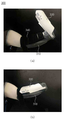
상기 제1 하드 커버(310)와 상기 제2 하드 커버(330)의 상대적인 회전에 따라, 착용 편의성이 향상될 수 있다. 예를 들어, 도 14(a)에 도시된 바와 같이, 제2 하드 커버(330)를 제1 하드 커버(310)에 대하여 오픈한 상태에서, 절단되고 남은 팔의 일부를 넣고, 도 14(b)에 도시된 바와 이, 제2 하드 커버(330)를 닫을 수 있다.As the first
도 13을 참조하면, 상기 제1 하드 커버(310)에는 전선 트랙(320)이 마련될 수 있다. 상기 전선 트랙(320)에는 전선 예를 들어, 상술한 제1 및/또는 제2 액츄에이터를 구동시키기 위한 전선이 수납 정리될 수 있다.Referring to FIG. 13, an
상기 제1 하드 커버(310)와 상기 제2 하드 커버(330)는 소정의 강성을 가지는 소재로 이루어질 수 있다. 이를 통하여, 외부의 충격으로부터, 내측에 수용되는 절단되고 남은 팔을 보호할 수 있다.The first
도 14를 참조하면, 소프트 커버(340)는 신체의 일부를 직접 감싸는 기능을 수행할 수 있다. 이를 위하여, 상기 소프트 커버(340)는 신체의 크기에 따라 체결 강도를 조절할 수 있도록 벨크로 타입 스트랩으로 이루어질 수 있다. 이에 따라, 불규칙한 절단 부위를 전체적으로 감쌀 수 있어 고정력이 향상될 수 있다.Referring to FIG. 14, the
상기 소프트 커버(340)는 피부와 직접 접촉할 수 있다. 착용감 향상을 위하여 소프트 커버(340)는 제1 및 제2 하드 커버(310, 330) 보다 부드러운 소재로 이루어질 수 있다. The
일 예에 따르면, 상기 소프트 커버(340)와 피부 사이에 슬리브(sleeve, 미도시)가 마련될 수 있다. 슬리브는 상기 소프트 커버(340) 보다 부드러운 소재로 이루어질 수 있다. 이는 절단되고 남은 환자의 피부가 보통 사람보다 예민한 것을 고려한 것이다. According to an example, a sleeve (not shown) may be provided between the
이에 따르면, 사용자는 먼저 슬리브를 착용하고, 슬리브 상에 소프트 커버(340)를 착용할 수 있다. 이후, 도 14(a) 및 도 14(b)에 도시된 바와 같이, 제1 및 제2 하드 커버(310, 330) 공간에 소프트 커버(340)를 고정할 수 있다.According to this, the user may first wear the sleeve and then the
이상 설명한 본 발명의 일 실시 예에 따른 로봇 메커니즘을 설명함에 있어서, 팔의 일부가 절단된 경우를 상정하여 설명하였으나, 일 실시 예에 따른 로봇 메커니즘은 신체의 다른 부위가 절단된 환자에게도 적용될 수 있음은 물론이다.In the description of the robot mechanism according to an embodiment of the present invention described above, it is assumed that a part of the arm is amputated, but the robot mechanism according to an embodiment may be applied to a patient whose other part of the body is amputated. Of course.
또한, 일 실시 예에 따른 로봇 메커니즘은, 신체 절단 환자 뿐 아니라, 가정용 및/또는 산업용 로봇에 적용될 수도 있다. In addition, the robot mechanism according to an embodiment may be applied not only to a body amputated patient, but also to a home and/or industrial robot.
이상, 본 발명을 바람직한 실시 예를 사용하여 상세히 설명하였으나, 본 발명의 범위는 특정 실시 예에 한정되는 것은 아니며, 첨부된 특허청구범위에 의하여 해석되어야 할 것이다. 또한, 이 기술분야에서 통상의 지식을 습득한 자라면, 본 발명의 범위에서 벗어나지 않으면서도 많은 수정과 변형이 가능함을 이해하여야 할 것이다.In the above, the present invention has been described in detail using preferred embodiments, but the scope of the present invention is not limited to specific embodiments, and should be interpreted by the appended claims. In addition, those who have acquired ordinary knowledge in this technical field should understand that many modifications and variations can be made without departing from the scope of the present invention.
1000: 로봇 메커니즘 100: 말단 모듈
110: 제1 바디 132: 제1 축
134: 제2 축 130: 제3 축
120: 제1 기어 122: 제2-1 기어
124: 제2-2 기어 126: 제3 기어
128: 제4 기어 129: 제5 기어
140: 탄성 부재 152: 전달 링크
160: 제2 바디 162: 제1 링크
164: 탄성 부재 하우징 166: 체결공
165: 제4 축 169: 제5 축
168: 제2 링크 180: 제3 바디
200: 연결 모듈 210: 케이스
220: 제1 롤링 컨택부 230: 제2 롤링 컨택부
300: 착용 모듈 310: 제1 하드 커버
320: 전선 트랙 330: 제2 하드 커버
340: 소프트 커버1000: robot mechanism 100: end module
110: first body 132: first axis
134: second axis 130: third axis
120: first gear 122: 2-1 gear
124: second-2 gear 126: third gear
128: fourth gear 129: fifth gear
140: elastic member 152: transmission link
160: second body 162: first link
164: elastic member housing 166: fastening hole
165: fourth axis 169: fifth axis
168: second link 180: third body
200: connection module 210: case
220: first rolling contact unit 230: second rolling contact unit
300: wearing module 310: first hard cover
320: electric wire track 330: second hard cover
340: soft cover
Claims (12)
일 단에 상기 탄성 부재를 수용하는 탄성 부재 하우징을 통하여 상기 제1 축에 연동 회전하는 제1 링크 및 상기 제2 축에 연결되어 연동 피봇팅하는 제2 링크를 포함하는, 제2 바디; 및
상기 제2 바디의 일 단에 마련되어, 상기 제2 링크의 피봇팅에 따라 회전하는, 제3 바디;를 포함하되,
상기 제1 축의 회전에도 불구하고, 상기 제2 바디의 제1 링크의 연동 회전이 중지된 경우, 상기 제2 축에 연결된 상기 제2 링크의 피봇팅에 따라, 상기 제3 바디가 상기 제2 바디와 독립적으로 회전하는, 로봇 메커니즘.A first body provided with an elastic member on one side and including a first shaft to which one end of the transmission link is connected to the other side, and a second shaft to which the first shaft and the other end of the transmission link are coupled;
A second body including a first link interlockedly rotated with the first shaft through an elastic member housing accommodating the elastic member at one end and a second link connected to the second shaft for interlocking pivoting; And
Including; provided at one end of the second body, a third body rotating according to the pivoting of the second link,
When the interlocking rotation of the first link of the second body is stopped despite the rotation of the first axis, the third body becomes the second body according to the pivoting of the second link connected to the second axis. Rotating independently of the, robotic mechanism.
상기 제1 축의 회전력이 상기 탄성 부재를 통하여 상기 탄성 부재 하우징을 회전시킴에 따라, 상기 제1 링크가 회전되는, 로봇 메커니즘.The method of claim 1,
As the rotational force of the first axis rotates the elastic member housing through the elastic member, the first link is rotated.
상기 탄성 부재 하우징은, 상기 탄성 부재가 결합되는 체결공을 가지고,
상기 탄성 부재는 코일부와 상기 체결공에 거치되는 선형부를 가지는, 로봇 메커니즘.The method of claim 2,
The elastic member housing has a fastening hole to which the elastic member is coupled,
The elastic member has a coil portion and a linear portion mounted in the fastening hole, the robot mechanism.
상기 제1 축은, 상기 제1 링크의 회전이 중지된 상태에서도, 상기 탄성 부재의 변형에 따라 지속 회전하는, 로봇 메커니즘.The method of claim 1,
The first shaft, even in a state in which the rotation of the first link is stopped, continuously rotates according to the deformation of the elastic member.
상기 탄성 부재의 변형에 따라 상기 제1 축이 회전하는 경우, 상기 제2 축은 상기 제1 축에 대하여 피봇팅하는, 로봇 메커니즘.The method of claim 4,
When the first axis rotates according to the deformation of the elastic member, the second axis pivots about the first axis.
상기 탄성 부재의 변형 복원에 따라, 상기 제1 링크가 초기 위치로 복원하는, 로봇 메커니즘.The method of claim 4,
In accordance with the deformation restoration of the elastic member, the first link is restored to an initial position.
제1 액츄에이터의 회전력을 전달하는 제1 기어,
제3 축에 마련되되, 상기 제1 기어로부터 회전력을 전달받는 제2 기어 및 상기 제2 기어가 상기 제3 축을 회전시키는 경우, 회전하는 제5 기어,
상기 제1 축에 마련되되, 상기 제2 기어로부터 회전력을 전달받아 상기 제1 축으로 전달하는 제3 기어, 상기 제5 기어로부터 회전력을 전달받아 상기 제1 축으로 전달하는 제4 기어를 더 포함하는, 로봇 메커니즘.The method of claim 1,
A first gear that transmits the rotational force of the first actuator,
A fifth gear provided on a third shaft, which rotates when the second gear and the second gear that receive rotational force from the first gear rotate the third shaft,
A third gear provided on the first shaft and receiving rotational force from the second gear and transmitting it to the first axis, and a fourth gear receiving rotational force from the fifth gear and transmitting it to the first axis. That, the robotic mechanism.
제1 액츄에이터를 더 포함하며,
상기 제1 바디와 상기 제1 액츄에이터 사이에 마련되고, 상기 제1 바디가 결합하는 결합 하우징을 더 포함하며,
상기 결합 하우징에 마련되며, 상기 제1 링크의 회전 방향과 다른 방향으로의 움직임을 허용하는 탄성 부재를 더 포함하는, 로봇 메커니즘.The method of claim 1,
Further comprising a first actuator,
Further comprising a coupling housing provided between the first body and the first actuator, the first body coupled,
The robot mechanism is provided in the coupling housing, further comprising an elastic member that allows movement in a direction different from the rotation direction of the first link.
상기 제1 바디의 일 측에 결합되는, 연결 모듈을 더 포함하며,
상기 연결 모듈은:
회전력을 생성하며, 제1 풀리가 체결된 제2 액츄에이터;
상기 제1 풀리와 제1 방향으로 대향하는 제2 풀리;
소정 간격 서로 이격하되, 상기 제1 풀리와 상기 제1 바디 방향으로 대향하는 제3-1 풀리 및 상기 제2 풀리와 상기 제1 바디 방향으로 대향하는 제4-1 풀리가 배치되는 제1 롤링 컨택부;
상기 제1 롤링 컨택부에서 상기 제1 바디 방향으로 배치되며, 상기 제3-1 풀리와 상기 제1 바디 방향으로 대향하는 제5-1 풀리 및 상기 제4-1 풀리와 상기 제1 바디 방향으로 대향하는 제6-1 풀리가 배치되는 제2 롤링 컨택부; 및
상기 제1 풀리와 상기 제4-1 풀리 및 상기 제6-1 풀리를 순차적으로 연결하고, 상기 제2 풀리와 상기 제3-1 풀리 및 상기 제5-1 풀리를 순차적으로 연결하는, 와이어를 포함하는, 로봇 메커니즘.The method of claim 1,
Further comprising a connection module coupled to one side of the first body,
The connection module is:
A second actuator to generate a rotational force and to which the first pulley is fastened;
A second pulley facing the first pulley in a first direction;
A first rolling contact spaced apart from each other by a predetermined distance, wherein a 3-1 pulley facing the first pulley and the first body direction, and a 4-1 pulley facing the second pulley and the first body direction are disposed part;
A 5-1 pulley disposed from the first rolling contact portion in a direction of the first body and facing the 3-1 pulley in a direction of the first body, and a direction of the 4-1 pulley and the first body A second rolling contact portion on which the 6-1 opposing pulley is disposed; And
The first pulley, the 4-1 pulley, and the 6-1 pulley are sequentially connected, and the second pulley, the 3-1 pulley, and the 5-1 pulley are sequentially connected, a wire Including, robotic mechanism.
상기 제2 액츄에이터의 회전력에 의한 상기 와이어의 장력 조절에 따라,
상기 제2 롤링 컨택부는, 상기 제1 롤링 컨택부에 대하여 상대 회동하는, 로봇 메커니즘.The method of claim 10,
According to the tension control of the wire by the rotational force of the second actuator,
The robot mechanism, wherein the second rolling contact portion rotates relative to the first rolling contact portion.
절단되고 남은 신체 일 측에 체결되는 착용 모듈을 더 포함하며,
상기 착용 모듈은:
상기 남은 신체 일 측에 직접 체결되는 소프트 커버 및 상기 소프트 커버를 덮는 하드 커버를 포함하며,
상기 하드 커버에는, 상기 제1 축에 회전력을 제공하는 제1 액츄에이터에 전기를 공급하는 전선이 거치되는 전선 트랙이 마련되는, 로봇 메커니즘.
The method of claim 1,
Further comprising a wearing module fastened to one side of the body remaining after being cut,
The wearing module is:
A soft cover directly fastened to one side of the remaining body and a hard cover covering the soft cover,
The hard cover is provided with a wire track on which a wire for supplying electricity to a first actuator that provides rotational force to the first shaft is mounted.
Priority Applications (1)
| Application Number | Priority Date | Filing Date | Title |
|---|---|---|---|
| KR1020190064057A KR102194508B1 (en) | 2019-05-30 | 2019-05-30 | Robot Mechanism |
Applications Claiming Priority (1)
| Application Number | Priority Date | Filing Date | Title |
|---|---|---|---|
| KR1020190064057A KR102194508B1 (en) | 2019-05-30 | 2019-05-30 | Robot Mechanism |
Publications (2)
| Publication Number | Publication Date |
|---|---|
| KR20200137534A KR20200137534A (en) | 2020-12-09 |
| KR102194508B1 true KR102194508B1 (en) | 2020-12-23 |
Family
ID=73786703
Family Applications (1)
| Application Number | Title | Priority Date | Filing Date |
|---|---|---|---|
| KR1020190064057A Active KR102194508B1 (en) | 2019-05-30 | 2019-05-30 | Robot Mechanism |
Country Status (1)
| Country | Link |
|---|---|
| KR (1) | KR102194508B1 (en) |
Cited By (1)
| Publication number | Priority date | Publication date | Assignee | Title |
|---|---|---|---|---|
| US20250058458A1 (en) * | 2022-05-04 | 2025-02-20 | Naver Corporation | Joint apparatus for robot |
Citations (1)
| Publication number | Priority date | Publication date | Assignee | Title |
|---|---|---|---|---|
| JP2009028859A (en) | 2007-07-27 | 2009-02-12 | Toshiba Corp | Manipulator and robot |
Family Cites Families (4)
| Publication number | Priority date | Publication date | Assignee | Title |
|---|---|---|---|---|
| JPH01146682A (en) * | 1987-12-03 | 1989-06-08 | Bridgestone Corp | Robot hand |
| KR101610745B1 (en) * | 2014-06-16 | 2016-04-08 | 한국과학기술연구원 | Robot Finger structure |
| KR101639723B1 (en) * | 2014-10-21 | 2016-07-15 | 한국생산기술연구원 | a robot hand |
| KR101935144B1 (en) * | 2017-02-23 | 2019-03-18 | 고려대학교 산학협력단 | Robot arm equipped with counterbalance mechanism |
-
2019
- 2019-05-30 KR KR1020190064057A patent/KR102194508B1/en active Active
Patent Citations (1)
| Publication number | Priority date | Publication date | Assignee | Title |
|---|---|---|---|---|
| JP2009028859A (en) | 2007-07-27 | 2009-02-12 | Toshiba Corp | Manipulator and robot |
Cited By (2)
| Publication number | Priority date | Publication date | Assignee | Title |
|---|---|---|---|---|
| US20250058458A1 (en) * | 2022-05-04 | 2025-02-20 | Naver Corporation | Joint apparatus for robot |
| US12440962B2 (en) * | 2022-05-04 | 2025-10-14 | Naver Corporation | Joint apparatuses for robot |
Also Published As
| Publication number | Publication date |
|---|---|
| KR20200137534A (en) | 2020-12-09 |
Similar Documents
| Publication | Publication Date | Title |
|---|---|---|
| US12390293B2 (en) | Parallel kinematic mechanisms with decoupled rotational motions | |
| CA2631982C (en) | Hand prosthesis | |
| EP3226824B1 (en) | Aid device for the movement and/or rehabilitation of one or more fingers of a hand | |
| CN110520256B (en) | Under-actuated robot hand | |
| Cappello et al. | Design and preliminary characterization of a soft wearable exoskeleton for upper limb | |
| US8915528B2 (en) | Gripping device | |
| ITPI20120069A1 (en) | EXOSCHELETER FOR PHYSICAL INTERACTION WITH THE MAN | |
| EP3723943B1 (en) | Driving assembly for moving body part | |
| JP2010064242A (en) | Robot hand and human type robot equipped with robot hand | |
| EP3334572A1 (en) | Exosuit | |
| JP2009519795A (en) | Prosthetic hand and force transmission means | |
| CN112356014B (en) | Underactuated coupled adaptive hand exoskeleton robot | |
| CN103690279A (en) | An underactuated prosthetic hand system based on a planetary gear train | |
| CN100581756C (en) | Duplex bevel gear underactuated robot finger | |
| KR102194508B1 (en) | Robot Mechanism | |
| WO2017187288A1 (en) | Bi-directional underactuated exoskeleton | |
| CN117243792B (en) | A multi-limb hand robot system | |
| EP3802007A1 (en) | Device comprising input and output pulleys on nonparallel or parallel and mutually hingeable axes | |
| KR20220119847A (en) | Hybrid type joint driving system | |
| Nasser et al. | Design of an anthropomorphic underactuated hand prosthesis with passive-adaptive grasping capabilities | |
| KR102195315B1 (en) | Prosthetic Hand Module | |
| CN114028043A (en) | Bionic finger prosthesis | |
| KR20100008867A (en) | Robot hand and humanoid robot having the same | |
| KR102345634B1 (en) | Underactuation mechanism of wrist and forearm which is capable of fullyindependent motion in each degrees of freedom | |
| JP7835405B2 (en) | Prosthetic arm |
Legal Events
| Date | Code | Title | Description |
|---|---|---|---|
| PA0109 | Patent application |
St.27 status event code: A-0-1-A10-A12-nap-PA0109 |
|
| PA0201 | Request for examination |
St.27 status event code: A-1-2-D10-D11-exm-PA0201 |
|
| D13-X000 | Search requested |
St.27 status event code: A-1-2-D10-D13-srh-X000 |
|
| D14-X000 | Search report completed |
St.27 status event code: A-1-2-D10-D14-srh-X000 |
|
| E902 | Notification of reason for refusal | ||
| PE0902 | Notice of grounds for rejection |
St.27 status event code: A-1-2-D10-D21-exm-PE0902 |
|
| E13-X000 | Pre-grant limitation requested |
St.27 status event code: A-2-3-E10-E13-lim-X000 |
|
| P11-X000 | Amendment of application requested |
St.27 status event code: A-2-2-P10-P11-nap-X000 |
|
| P13-X000 | Application amended |
St.27 status event code: A-2-2-P10-P13-nap-X000 |
|
| PG1501 | Laying open of application |
St.27 status event code: A-1-1-Q10-Q12-nap-PG1501 |
|
| E701 | Decision to grant or registration of patent right | ||
| PE0701 | Decision of registration |
St.27 status event code: A-1-2-D10-D22-exm-PE0701 |
|
| GRNT | Written decision to grant | ||
| PR0701 | Registration of establishment |
St.27 status event code: A-2-4-F10-F11-exm-PR0701 |
|
| PR1002 | Payment of registration fee |
St.27 status event code: A-2-2-U10-U11-oth-PR1002 Fee payment year number: 1 |
|
| PG1601 | Publication of registration |
St.27 status event code: A-4-4-Q10-Q13-nap-PG1601 |
|
| R18-X000 | Changes to party contact information recorded |
St.27 status event code: A-5-5-R10-R18-oth-X000 |
|
| PR1001 | Payment of annual fee |
St.27 status event code: A-4-4-U10-U11-oth-PR1001 Fee payment year number: 4 |
|
| PR1001 | Payment of annual fee |
St.27 status event code: A-4-4-U10-U11-oth-PR1001 Fee payment year number: 5 |
|
| PR1001 | Payment of annual fee |
St.27 status event code: A-4-4-U10-U11-oth-PR1001 Fee payment year number: 6 |
|
| U11 | Full renewal or maintenance fee paid |
Free format text: ST27 STATUS EVENT CODE: A-4-4-U10-U11-OTH-PR1001 (AS PROVIDED BY THE NATIONAL OFFICE) Year of fee payment: 6 |