KR101610745B1 - Robot Finger structure - Google Patents
Robot Finger structure Download PDFInfo
- Publication number
- KR101610745B1 KR101610745B1 KR1020140072747A KR20140072747A KR101610745B1 KR 101610745 B1 KR101610745 B1 KR 101610745B1 KR 1020140072747 A KR1020140072747 A KR 1020140072747A KR 20140072747 A KR20140072747 A KR 20140072747A KR 101610745 B1 KR101610745 B1 KR 101610745B1
- Authority
- KR
- South Korea
- Prior art keywords
- link
- joint
- nodal
- crank
- crankshaft
- Prior art date
- Legal status (The legal status is an assumption and is not a legal conclusion. Google has not performed a legal analysis and makes no representation as to the accuracy of the status listed.)
- Expired - Fee Related
Links
Images


Classifications
-
- B—PERFORMING OPERATIONS; TRANSPORTING
- B25—HAND TOOLS; PORTABLE POWER-DRIVEN TOOLS; MANIPULATORS
- B25J—MANIPULATORS; CHAMBERS PROVIDED WITH MANIPULATION DEVICES
- B25J13/00—Controls for manipulators
- B25J13/02—Hand grip control means
-
- B—PERFORMING OPERATIONS; TRANSPORTING
- B25—HAND TOOLS; PORTABLE POWER-DRIVEN TOOLS; MANIPULATORS
- B25J—MANIPULATORS; CHAMBERS PROVIDED WITH MANIPULATION DEVICES
- B25J15/00—Gripping heads and other end effectors
- B25J15/08—Gripping heads and other end effectors having finger members
Landscapes
- Engineering & Computer Science (AREA)
- Robotics (AREA)
- Mechanical Engineering (AREA)
- Manipulator (AREA)
Abstract
로봇 손가락 구조체는 모터와, 상기 모터에 의해 회전하는 크랭크축과, 상기 크랭크축에 연결되어 상기 크랭크축을 중심으로 회전하는 크랭크와, 제1조인트에서 상기 크랭크와 연결되는 제1마디 링크와, 제4조인트에서 상기 제1마디 링크와 연결되는 제2마디 링크와, 제2조인트에서 상기 크랭크와 연결되며 상기 크랭크의 회전력을 상기 제2마디 링크에 전달하는 제1연결 링크 및 상기 제1마디 링크가 상기 크랭크에 대해 자유 회전하는 것을 구속하는 제1강성을 부여하는 제1강성 부여 기구를 포함하고, 물체와 접촉하지 않은 상태에서 상기 크랭크가 회전하면 상기 제1마디 링크와 상기 제2마디 링크가 서로 상대적 위치를 유지하며 상기 크랭크와 함께 회전하고,상기 제1마디 링크가 물체에 접촉하여 상기 제1마디 링크의 회전이 저지되면 상기 크랭크가 상기 제1강성을 극복하며 회전하여 상기 제2마디 링크를 상기 제1마디 링크에 대해 회전시킨다. The robot finger structure includes a motor, a crankshaft rotated by the motor, a crank connected to the crankshaft and rotating about the crankshaft, a first nodal link connected to the crank at a first joint, A second joint link connected to the first joint link at a joint, a first joint link connected to the crank at a second joint and transmitting a rotational force of the crank to the second joint link, And a first rigidity imparting mechanism for imparting a first rigidity that restrains free rotation of the crank with respect to the crank, and when the crank rotates in a state of not contacting the object, the first and second nodal links are relatively And when the rotation of the first nodal link is blocked by the first nodal link contacting the object, the crank Group is rotated about the second joint link and overcome to rotate the first rigidity of the first bar link.

Description
본 발명은 로봇 손가락 구조체에 관한 것으로서, 더욱 상세하게는 로봇을 이용한 물체의 파지 작업이 요구되는 각종 분야에 적용될 수 있는 로봇의 손가락 구조체에 관한 것이다. BACKGROUND OF THE INVENTION 1. Field of the Invention [0002] The present invention relates to a robot finger structure, and more particularly, to a finger structure of a robot that can be applied to various fields requiring a gripping operation of an object using a robot.
사람의 손가락은 구부러질 수 있는 마디가 있어 물체를 집거나 파지하기가 용이하다. The fingers of a person are easy to grasp or grasp an object by means of bent nodes.
로봇 암을 이용한 작업 수행시 물체의 용이한 파지를 위해 사람의 손가락과 유사한 구조의 손가락 구조체가 이용되고 있다. In order to easily grasp an object when a robot arm is used, a finger structure having a structure similar to that of a human finger is used.
하지만, 종래에 로봇에 이용되는 손가락 구조체는 복수의 마디로 이루어진 구조를 채용하고는 있으나, 실제 사람의 손가락과 유사한 동작을 구현하고 있지 못하다. Conventionally, however, the finger structure used in the robot has adopted a structure composed of a plurality of nodes, but does not implement an action similar to that of a real person's finger.
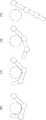
도 1은 사람의 손가락이 물체를 파지하는 과정을 도시한 개략도이고, 도 2는 종래 기술에 따른 로봇의 손가락 구조체를 이용해 물체를 파지하는 과정을 도시한 개략도이다. FIG. 1 is a schematic view showing a process in which a finger of a person grasps an object, and FIG. 2 is a schematic view illustrating a process of grasping an object using a finger structure of a robot according to the related art.
도 1에 도시된 바와 같이, 실제 사람이 물체를 감싸쥘 때의 동작을 살펴보면, 먼저 손가락이 전체적으로 물체를 향해 다가가고 손가락의 첫마디가 먼저 물체에 접촉하면 중간 마디가 첫마디에 대해 구부러지고 동시에 끝 마디가 중간 마디에 대해 구부러지는 동작이 함께 수행되면서 물체를 감싸게 된다. 중간 마디가 물체에 접촉하면 끝 마디가 중간 마디에 대해 구부러져 물체를 완전히 감싸쥐게 된다. As shown in FIG. 1, when an object is wrapped around an object, the finger first approaches the object as a whole, and when the first finger of the finger first touches the object, the middle point is bent with respect to the first point, Is bent together with respect to the middle node, thereby wrapping the object. When the middle node touches the object, the end node bends against the middle node and completely holds the object.
이와 비교하여, 도 2에 도시된 바와 같이, 종래 기술에 따른 손가락 구조체를 이용해 물체를 감싸쥘 때의 동작을 살펴보면, 손가락의 첫마디가 물체에 접촉한 뒤 중간 마디와 끝 마디가 서로 상대적인 위치를 그대로 유지하면서 첫마디에 대해 구부러지고, 중간 마디가 물체에 접촉하면 끝 마디가 중간 마디에 대해 구부러지는 방식으로 파지 동작을 수행한다. In contrast, as shown in FIG. 2, when an object is wrapped around using a finger structure according to the related art, when the first finger of the finger touches an object, And the gripping operation is performed in such a manner that the ending node is bent with respect to the middle node when the middle node touches the object.
이러한 종래 기술의 손가락 구조체는, 파지 동작 메커니즘이 실제 사람의 파지 동작과 일치하지 않으므로, 의수 등에 적용하는 경우 동작이 매우 부자연스럽게 된다. 또한, 안정적이고 세밀한 파지 동작이 수행되기 어렵다. Such a finger structure according to the related art does not coincide with the grasping operation of an actual person, so that the operation becomes very unnatural when applied to the grasp or the like. In addition, stable and detailed gripping operation is difficult to perform.
나아가, 종래의 손가락 구조체는 기어 및 볼 스크류 등을 이용하여 구조가 복잡하여 소형화가 어렵고, 사용자의 안전성 면에서도 바람직하지 않은 경우가 많다. Furthermore, the conventional finger structure is complicated in structure due to the use of gears, ball screws, and the like, so that it is difficult to miniaturize the finger structure and it is often undesirable from the standpoint of safety of the user.
상술한 종래기술의 문제점을 해결하기 위해, 본 발명은 파지시 사람의 손가락 동작에 최대한 근접하여 자연스러운 동작을 구현할 수 있고, 추가적인 링크구조를 사용하지 않고도 손가락 마디마다 직접적인 힘 전달이 가능하여 사람의 근력보조장치, 의수 등에도 적절히 사용될 수 있는 로봇 손가락 구조체를 제공하는 것을 목적으로 한다. In order to solve the problems of the prior art described above, the present invention can realize a natural operation as close as possible to a finger operation of a person in gripping, and can transmit force directly to each finger without using an additional link structure, It is an object of the present invention to provide a robot finger structure which can be suitably used for an auxiliary device,
상기 목적을 달성하기 위하여, 본 발명의 일 측면에 따르면, 모터와, 상기 모터에 의해 회전하는 크랭크축과, 상기 크랭크축에 연결되어 상기 크랭크축을 중심으로 회전하는 크랭크와, 제1조인트에서 상기 크랭크와 연결되는 제1마디 링크와, 제4조인트에서 상기 제1마디 링크와 연결되는 제2마디 링크와, 제2조인트에서 상기 크랭크와 연결되며 상기 크랭크의 회전력을 상기 제2마디 링크에 전달하는 제1연결 링크 및 상기 제1마디 링크가 상기 크랭크에 대해 자유 회전하는 것을 구속하는 제1강성을 부여하는 제1강성 부여 기구를 포함하고, 물체와 접촉하지 않은 상태에서 상기 크랭크가 회전하면 상기 제1마디 링크와 상기 제2마디 링크가 서로 상대적 위치를 유지하며 상기 크랭크와 함께 회전하고,상기 제1마디 링크가 물체에 접촉하여 상기 제1마디 링크의 회전이 저지되면 상기 크랭크가 상기 제1강성을 극복하며 회전하여 상기 제2마디 링크를 상기 제1마디 링크에 대해 회전시키는 로봇 손가락 구조체가 제공된다. In order to achieve the above object, according to one aspect of the present invention, there is provided a motor comprising a motor, a crankshaft rotated by the motor, a crank connected to the crankshaft and rotating about the crankshaft, A second joint link connected to the first joint link at a fourth joint and a second joint link connected to the crank at a second joint and transmitting the rotational force of the crank to the second joint link, 1 link link and a first rigidity imparting mechanism for imparting a first rigidity to restrain free rotation of the first nodal link relative to the crank, wherein when the crank rotates in a state of not contacting the object, The first nodal link is in contact with an object so that the first nodal link and the second nodal link rotate together with the crank maintaining their relative positions relative to each other, When the rotation of the stop of the robot finger structure for the crank to overcome the stiffness of the first and rotated by the second rotation with respect to the first joint link, the node link is provided.
일 실시예에 따르면, 상기 제1연결 링크는, 상기 제1조인트에서 상기 크랭크와 연결되는 제1전달 링크와, 일단이 제3조인트에서 상기 제1전달 링크와 연결되고, 타단이 상기 제4조인트에 연결되는 제2전달 링크를 포함하고, 상기 제2마디 링크가 상기 제2전달 링크에 대해 자유 회전하는 것을 구속하는 제2강성을 부여하는 제2강성 부여 기구가 구비된다. According to one embodiment, the first connection link includes a first transmission link connected to the crank at the first joint, a second transmission link connected at one end to the first transmission link at the third joint, And a second stiffness imparting mechanism that imparts a second stiffness to restrain free rotation of the second nodal link with respect to the second transmission link.
일 실시예에 따르면, 로봇 손가락 구조체는 제7조인트에서 상기 제2마디 링크와 연결되는 제3마디 링크와, 상기 크랭크의 회전력을 상기 제3마디 링크에 전달하는 제2연결 링크를 더 포함하고, 물체와 접촉하지 않은 상태에서 상기 크랭크가 회전하면 상기 제1마디 링크, 상기 제2마디 링크 및 상기 제3마디 링크가 서로 상대적 위치를 유지하며 상기 크랭크와 함께 회전하고, 상기 제2마디 링크가 물체에 접촉하여 상기 제2마디 링크의 회전이 저지되면 상기 크랭크가 상기 제2강성을 극복하며 회전하여 상기 제3마디 링크를 상기 제2마디 링크에 대해 회전시킨다. According to one embodiment, the robot finger structure further comprises a third joint link connected to the second joint link at a seventh joint, and a second joint link transmitting the rotational force of the crank to the third joint link, Wherein the first nodal link, the second nodal link, and the third nodal link maintain a relative position with respect to each other and rotate with the crank when the crank rotates without contact with an object, And when the rotation of the second nodal link is blocked, the crank rotates to overcome the second rigidity to rotate the third nodal link about the second nodal link.
일 실시예에 따르면, 상기 제2연결 링크는, 크랭크와 함께 회전하는 제3전달 링크와, 일단이 제6조인트에서 상기 제3전달 링크와 연결되고, 타단이 상기 제7조인트에 연결되는 제4전달 링크를 포함하고, 상기 제3마디 링크가 상기 제4전달 링크에 대해 자유 회전하는 것을 구속하는 제3강성을 부여하는 제3강성 부여 기구가 구비된다. According to one embodiment, the second connection link includes a third transmission link rotating together with the crank, and a fourth transmission link having one end connected to the third transmission link at the sixth joint and the other end connected to the seventh joint, And a third stiffness-imparting mechanism that includes a transmission link and imparts a third stiffness that restrains the third nodal link from rotating freely relative to the fourth transmission link.
일 실시예에 따르면, 상기 제3전달 링크는 제5조인트에서 상기 크랭크와 연결된다. According to one embodiment, the third transmission link is connected to the crank at a fifth joint.
일 실시예에 따르면, 상기 제3마디 링크가 물체와 접촉하면 상기 크랭크가 상기 제1강성 및 제2강성을 극복하며 회전하여 상기 제1마디 링크, 제2마디 링크 및 제3마디 링크에 힘을 전달한다. According to one embodiment, when the third nodal link contacts an object, the crank rotates to overcome the first and second rigidities to exert a force on the first nodal link, the second nodal link, and the third nodal link .
일 실시예에 따르면, 상기 제1강성 부여 기구, 상기 제2강성 부여 기구 및 상기 제3강성 부여 기구는 토션 스프링일 수 있다. According to one embodiment, the first stiffness imparting mechanism, the second stiffness imparting mechanism, and the third stiffness imparting mechanism may be torsion springs.
일 실시예에 따르면, 상기 제1강성 부여 기구, 상기 제2강성 부여 기구 및 상기 제3강성 부여 기구의 스프링 계수는 1: 0.5: 0.1이다. According to one embodiment, the spring coefficient of the first stiffness imparting mechanism, the second stiffness imparting mechanism, and the third stiffness imparting mechanism is 1: 0.5: 0.1.
일 실시예에 따르면, 상기 모터는 상기 크랭크축과 수직하게 연장되는 입력축을 포함하고, 상기 입력축과 상기 크랭크축은 구형 조인트(spherical joint) 기구에 의해 연결된다. According to one embodiment, the motor includes an input shaft extending perpendicular to the crankshaft, and the input shaft and the crankshaft are connected by a spherical joint mechanism.
일 실시예에 따르면, 상기 구형 조인트 기구는, 제1회전 조인트에서 상기 입력축에 고정되어 상기 입력축에 의해 회전하며 상기 입력축과 다른 방향으로 연장되는 만곡된 입력링크와, 제2회전 조인트에서 상기 입력링크와 연결되는 만곡된 커플러 링크와, 제3회전 조인트에서 상기 커플러 링크와 연결되는 만곡된 출력링크를 포함하고, 상기 출력링크는 제4회전 조인트에서 상기 크랭크축과 연결되고, 상기 모터의 회전 운동이 상기 입력링크의 회전을 발생시키고, 상기 입력링크의 회전력은 상기 커플러 링크를 통해 상기 출력링크의 회전을 발생시키며, 상기 출력링크의 회전에 의해 상기 크랭크축이 회전하여 상기 크랭크를 회전시킨다. According to one embodiment, the spherical joint mechanism comprises: a curved input link fixed to the input shaft at a first rotational joint, the curved input link rotating by the input shaft and extending in a direction different from the input shaft; Wherein the output link is connected to the crankshaft at a fourth rotary joint and wherein the rotational movement of the motor is controlled by a rotational movement of the crankshaft, Wherein rotation of the input link causes rotation of the input link to generate rotation of the output link via the coupler link and rotation of the output link causes the crankshaft to rotate to rotate the crank.
일 실시예에 따르면, 상기 제1회전 조인트, 제2회전 조인트, 제3회전 조인트 및 제4회전 조인트에서의 각 회전 중심축의 연장선은 한 점에서 만난다. According to one embodiment, the extension lines of the respective rotation center axes in the first rotating joint, the second rotating joint, the third rotating joint and the fourth rotating joint meet at one point.
일 실시예에 따르면, 로봇 손가락 구조체는 상기 제1마디 링크 및 상기 제2마디 링크를 사람의 손가락 마디에 고정할 수 있는 장착 보조구를 더 포함하여, 사람의 손에 부착 가능하다. According to one embodiment, the robotic finger structure further comprises a mounting aid that is capable of securing the first and second nerve links to the fingertip of a person, and is attachable to a human hand.
도 1은 사람의 손가락이 물체를 파지하는 과정을 도시한 개략도이다.
도 2는 종래 기술에 따른 로봇의 손가락 구조체를 이용해 물체를 파지하는 과정을 도시한 개략도이다.
도 3은 본 발명의 일 실시예에 따른 로봇 손가락 구조체의 구성을 기구학적 모델로 표현한 개략도이다.
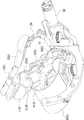
도 4 내지 도 6은 본 발명의 일 실시예에 따른 로봇 손가락 구조체를 서로 다른 각도에서 도시한 사시도이다.
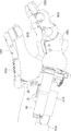
도 7은 본 발명의 일 실시예에 따른 로봇 손가락 구조체의 일부 구성을 분리한 분리 사시도이다.
도 8a 내지 도 8d는 본 발명의 일 실시예에 따른 손가락 구조체를 이용해 물체를 파지하는 과정을 도시한 것이다.
도 9는 본 발명의 일 실시예에 따른 손가락 구조체를 이용해 안정적인 집기 동작(pulp-pinch) 동작을 수행하는 모습을 도시한 것이다.
도 10은 본 발명의 일 실시예에 따른 구형 조인트 기구의 기구학적 구조를 나타낸 도면이다.
도 11 내지 도 13은 본 발명의 일 실시예에 따른 손가락 구조체를 외골격 형태로 형성한 모습을 도시한 것이다. 1 is a schematic view showing a process in which a human finger grasps an object.
2 is a schematic view showing a process of gripping an object using a finger structure of a robot according to the related art.
3 is a schematic view showing a configuration of a robot finger structure according to an embodiment of the present invention in a kinematic model.
4 to 6 are perspective views illustrating a robot finger structure according to an embodiment of the present invention at different angles.
FIG. 7 is an exploded perspective view illustrating a portion of a robot finger structure according to an embodiment of the present invention. Referring to FIG.
8A to 8D illustrate a process of gripping an object using a finger structure according to an embodiment of the present invention.
FIG. 9 illustrates a state in which a stable gripping operation (pulp-pinch) operation is performed using the finger structure according to an embodiment of the present invention.
10 is a view showing a kinematic structure of a spherical joint mechanism according to an embodiment of the present invention.
11 to 13 illustrate a finger structure according to an embodiment of the present invention formed in the form of an exoskeleton.
이하, 본 발명의 바람직한 실시예를 첨부한 도면을 참조하여 설명한다. 본 발명은 도면에 도시된 실시예를 참고로 설명되었으나 이는 하나의 실시예로서 설명되는 것이며, 이것에 의해 본 발명의 기술적 사상과 그 핵심 구성 및 작용은 제한되지 않는다. Hereinafter, preferred embodiments of the present invention will be described with reference to the accompanying drawings. Although the present invention has been described with reference to the embodiments shown in the drawings, it is to be understood that the technical idea of the present invention and its essential structure and action are not limited by this embodiment.
도 3은 본 발명의 일 실시예에 따른 로봇 손가락 구조체의 구성을 기구학적 모델로 표현한 개략도이다. 3 is a schematic view showing a configuration of a robot finger structure according to an embodiment of the present invention in a kinematic model.
도 3에 도시된 바와 같이, 본 실시예에 따른 손가락 구조체는 모터(80)(도 4 참조)에 의해 회전하는 크랭크축(2)과, 상기 크랭크축(2)에 연결되어 크랭크축(2)을 중심으로 회전하는 크랭크(60)와, 크랭크(60)로부터 차례로 직렬로 연결되는 제1마디 링크(10), 제2마디 링크(20) 및 제3마디 링크(30)를 포함한다. 3, the finger structure according to the present embodiment includes a
제1마디 링크(10), 제2마디 링크(20) 및 제3마디 링크(30)는 각각 손가락의 마디를 구성하게 된다. The
제1마디 링크(10)는 제1조인트(J1)에서 크랭크(60)와 연결된다. 제1마디 링크(10)는 크랭크(60)에 대해 자유 회전 가능하게 연결되며, 본 실시예에서 제1조인트(J1)는 크랭크축(5) 상에 형성된다. The first
제2마디 링크(20)는 제4조인트(J4)에서 제1마디 링크(10)와 연결된다. 제2마디 링크(20)는 제1마디 링크(10)에 대해 자유회전 가능하다. A
제3마디 링크(30)는 제7조인트(J7)에서 제2마디 링크(20)와 연결된다. 제3마디 링크(30)는 제2마디 링크(20)에 대해 자유회전 가능하다. The third
본 실시예에 따르면 하나의 크랭크(60)를 이용해 제1마디 링크(10), 제2마디 링크(20) 및 제3마디 링크(30)에 힘을 전달하여 파지 동작을 수행할 수 있다. According to the present embodiment, one
이를 위해, 손가락 구조체는 크랭크(60)의 회전력을 제2마디 링크(20)와 제3마디 링크(30)로 각각 전달하는 제1연결 링크(40) 및 제2연결 링크(50)를 포함한다. To this end, the finger structure includes a first connecting
제1연결 링크(40)는 제2조인트(J2)에서 크랭크(60)와 연결되어 크랭크(60)와 함께 회전하는 제1전달 링크(41)와, 일단이 제3조인트(J3)에서 제1전달 링크(41)와 연결되고 타단이 제4조인트(J4)에 연결되는 제2전달 링크(42)를 포함한다. The first connecting
제2연결 링크(50)는 제5조인트(J5)에서 크랭크(60)와 연결되어 크랭크(60)와 함께 회전하는 제3전달 링크(51)와, 일단이 제6조인트(J6)에서 제3전달 링크(51)와 연결되고 타단이 제7조인트(J7)에 연결되는 제4전달 링크(52)를 포함한다. The
본 실시예에서는 제3전달 링크(51)가 제5조인트(J5)에서 크랭크(60)와 연결되어 있지만, 다르게는 제3전달 링크(51)는 제3조인트(J3)에 연결될 수도 있다. 제3전달 링크(50)가 제3조인트(J3)에 연결된 경우 크랭크(60)의 회전력은 제1전달 링크(41)를 통해 제3전달 링크(50)로 전달된다. In this embodiment, the
크랭크(60) 상에 형성된 제1조인트(J1), 제2조인트(J2) 및 제5조인트(J5)는 크랭크(60)에서 서로 다른 위치에 형성된다. 본 실시예에서는 대략 삼각형으로 형성된 크랭크(60)의 각 꼭지점에 제1조인트(J1), 제2조인트(J2) 및 제5조인트(J5)가 형성된다. The first joint J 1 , the second joint J 2 and the fifth joint J 5 formed on the
본 실시예에서 "조인트"에 연결된 부재들은 해당 조인트 상에 형성되는 회전 중심축을 중심으로 서로에 대해 상대 회전이 가능하다는 점이 이해되어야 할 것이다. It should be understood that the members connected to the "joint" in this embodiment are capable of relative rotation relative to each other about a rotational center axis formed on the joint.
본 실시예에 따르면, 제1마디 링크(10), 제2마디 링크(20) 및 제3마디 링크(30)가 적절히 지지되도록 하는 한편, 하나의 크랭크(60)를 이용해 마디 링크(10, 20, 30)들의 상대 움직임을 유발시키기 위해 소정의 강성(stiffness)을 부여하는 강성 부여 기구가 구비된다. According to this embodiment, the first and second
도 3에 도시된 바와 같이, 제1강성 부여 기구(71), 제2강성 부여 기구(72) 및 제3강성 부여 기구(73)가 구비되며, 각각의 강성 부여 기구는 소정의 스프링 계수(k1, k2, k3)를 가지는 스프링이다. 3, a first stiffness imparting
제1강성 부여 기구(71)는 크랭크(60)와 제1마디 링크(10)와 관련되어, 제1마디 링크(10)가 크랭크(60)에 대해 자유 회전하는 것을 구속하는 제1강성을 부여한다. The first stiffness imparting
제2강성 부여 기구(72)는 제2전달 링크(42)와 제2마디 링크(20)와 관련되어, 제2마디 링크(20)가 제2전달 링크(42)에 대해 자유 회전하는 것을 구속하는 제2강성을 부여한다. The second
제3강성 부여 기구(73)는 제4전달 링크(52)와 제3마디 링크(30)와 관련되어, 제3마디 링크(30)가 제4전달 링크(52)에 대해 자유 회전하는 것을 구속하는 제3강성을 부여한다. The third stiffness imparting
이하, 도 4 내지 도 6을 참조하여, 본 실시예에 따른 로봇 손가락 구조체의 구성을 더 구체적으로 설명한다. Hereinafter, the configuration of the robot finger structure according to the present embodiment will be described in more detail with reference to Figs. 4 to 6. Fig.
도 4 내지 도 6은 본 실시예에 따른 로봇 손가락 구조체를 서로 다른 각도에서 도시한 사시도이다. FIGS. 4 to 6 are perspective views illustrating the robot finger structure according to the present embodiment at different angles.
도 4 내지 도 6에 도시된 바와 같이, 로봇 손가락 구조체는 크랭크 축(5)과 모터(80)를 고정 지지하기 위한 기초 프레임(81)을 포함한다. 4 to 6, the robot finger structure includes a
도 6에 가장 잘 도시된 바와 같이, 기초 프레임(81)은 크랭크축(5)을 회전 가능하게 고정하기 위한 축 고정부(83)와, 모터(80) 및 고정 링크(82)를 지지하는 몸체부(84)를 포함한다. 고정 링크(82)는 로봇의 엄지 손가락의 역할을 하게 된다.6, the
고정 링크(82)는 이동체(823)에 의해 기초 프레임(81)의 몸체부(84)에 고정되며, 이동체(823)를 이동시켜 고정 링크(82)를 기초 프레임(81)에 대해 전후방으로 위치 이동시킬 수도 있다. The fixed
고정 링크(82)는 이동체(823)로부터 연장되는 수직부(822)와 상기 수직부(822)로부터 구부러져 연장되는 수평부(821)를 포함한다. 수평부(821)에는 수평부(821)에 물체가 접촉하는지 여부를 감지할 수 있는 접촉 센서(미도시)가 구비될 수도 있다. 수평부(821)에 물체가 접촉하는 경우, 모터(80)를 구동하여 해당 물체를 파지하는 동작을 시작하도록 할 수 있다. The fixed
도 5에 도시된 바와 같이, 기초 프레임(81)의 축 고정부(83)에는 제1마디 링크(10)가 입력축(801)의 연장 방향으로부터 30도 이상 회전하는 것을 방지하기 위한 스토퍼(920)가 형성되어 있다. 제1마디 링크(10)가 물체와 접촉하지 않아도 스토퍼(920)에 접촉하는 경우 제1마디 링크(10)의 회전은 저지된다. 5, the
모터(80)는 크랭크축(5)과 수직한 방향으로 연장되는 입력축(801)을 포함한다. The
입력축(801)과 크랭크축(5)은 구형 4절 조인트 기구(90)에 의해 연결된다. 구형 4절 조인트 기구(90)의 구체적인 구성은 후술한다. The
크랭크(60)는 크랭크축(5)에 고정되어 크랭크축(5)과 함께 회전한다. 제1마디 링크(10)는 크랭크(60)의 위쪽에서 크랭크축(5)에 자유회전 가능하게 연결된다. The
제2마디 링크(20)는 대략 비대칭한 "工"자 형태를 가진다. 제4조인트(J4)에 위치하는 제2마디 링크(20)의 일 단부에는 축(86)(도 7 참조)이 상방으로 연장되고, 축(86)에 차례로 제2전달 링크(42)와 제1마디 링크(10)가 연결된다. The
자세히 도시하지는 않았지만, 제7조인트(J7)에 위치하는 제3마디 링크(30)의 단부에는 축이 상방으로 연장되고, 그 축에 제4전달 링크(52)와 제2마디 링크(20)가 연결된다. Although not shown in detail, the shaft is extended upward at the end of the
제1연결 링크(40)와 제2연결 링크(50)가 서로의 움직임을 간섭하지 않도록, 제1연결 링크(40)의 제1전달 링크(41)는 크랭크(60)의 위쪽 면에서 연결되고, 제2연결 링크(50)의 제3전달 링크(51)는 크랭크(60)의 아래쪽 면에서 연결된다. The
도시된 바와 같이, 각 링크 부재들은 서로의 움직임을 간섭하지 않으면서 구성이 간소화되도록 적절한 형태로 굴절 또는 만곡될 수 있다. As shown, each of the link members can be bent or bent in a proper shape so as to simplify the configuration without interfering with each other's movement.
도 7은 본 실시예에 따른 로봇 손가락 구조체의 일부 구성을 분리한 분리 사시도이다. 7 is an exploded perspective view showing a part of the structure of the robot finger structure according to the present embodiment.
도 7에 도시된 바와 같이, 크랭크축(5)에 고정된 크랭크(60)의 제1조인트(J1)에는 제1강성 부여 기구로서 제1토션 스프링(710)이 배치된다. 제1토션 스프링(710)은 크랭크(60)와 제1마디 링크(10)에 연결된다. 7, a
제1토션 스프링(710)의 탄성력이 제공하는 강성에 의해 크랭크(60)와 제1마디 링크(10)의 자유회전을 구속하게 된다. The free rotation of the first
이와 유사하게, 제4조인트(J4)에는 제2강성 부여 기구로서 제2토션 스프링(720)이 배치된다. 제2토션 스프링(720)은 제2전달 링크(42)와 제2마디 링크(20)에 연결된다. Similarly, the fourth joint (J 4), the
제2토션 스프링(720)의 탄성력이 제공하는 강성에 의해 제2전달 링크(42)와 제2마디 링크(20)의 자유회전을 구속하게 된다. And the free rotation of the
또한, 자세히 도시하지는 않았지만, 제7조인트(J7)에는 제3강성 부여 기구로서 제3토션 스프링(730)이 배치된다. 제3토션 스프링(730)은 제4전달 링크(52)와 제3마디 링크(30)에 연결된다. . Further, although not shown in detail, the seventh joint (J 7), the second the
제3토션 스프링(730)의 탄성력이 제공하는 강성에 의해 제4전달 링크(52)와 제3마디 링크(30)의 자유회전을 구속하게 된다.The free rotation of the
이와 같은 구성에 따르면, 사람의 손가락의 실제 동작과 매우 유사한 동작을 수행할 수 있다. According to such a configuration, an operation very similar to the actual operation of the human finger can be performed.
도 3 및 도 8a 내지 도 8d를 참조하여, 손가락 구조체를 이용해 물체를 파지하는 과정을 설명한다. A process of gripping an object using the finger structure will be described with reference to Figs. 3 and 8A to 8D. Fig.
도 8a 내지 도 8d는 본 실시예에 따른 손가락 구조체를 이용해 물체를 파지하는 과정을 도시한 것이다. 8A to 8D show a process of gripping an object using the finger structure according to the present embodiment.
물체와의 접촉 등에 의한 외력이 작용하지 않은 상태에서는 제1강성 부여 기구(71), 제2강성 부여 기구(72) 및 제3강성 부여 기구(73)가 부여하는 강성에 의해 손가락 구조체의 링크들의 상대 운동이 모두 구속된다. The rigidity imparted by the first
따라서, 마디 링크들(10, 20, 30)에 물체가 접촉하지 않은 상태에서 크랭크(60)가 크랭크축(2)을 중심으로 (도 3에서 반시계 방향으로) 회전하면, 제1마디 링크(10), 제2마디 링크(20) 및 제3마디 링크(30)가 서로 상대적 위치를 유지하며 크랭크(60)와 함께 동일 방향으로 전체적으로 회전한다(도 8a -> 도 8b). Therefore, when the
제1마디 링크(10), 제2마디 링크(20) 및 제3마디 링크(30)가 함께 회전하는 도중, 파지하고자 하는 물체가 제1마디 링크(10)에 먼저 접촉하게 되면 제1마디 링크(10)는 더 이상의 회전이 저지되어 움직임이 구속된다. When the object to be gripped first contacts the first
본 실시예에 따른 크랭크(60)의 회전력은 제1강성 부여 기구(71)가 제공하는 제1강성, 제2강성 부여 기구(71)가 제공하는 제2강성 및 제3강성 부여 기구(71)가 제공하는 제3강성을 극복하여 회전할 수 있을 만큼 크다. The rotational force of the
따라서, 제1마디 링크(10)의 움직임이 물체에 의해 구속된 경우에도, 크랭크(60)는 제1강성 부여 기구(71)가 제공하는 제1강성을 극복하여 제1강성 부여 기구(71)를 구부리면서 계속 회전 가능하다. Therefore, even when the movement of the first
크랭크(60)가 회전하면, 제2조인트(J2)가 크랭크축(2)을 중심으로 회전하면서 그에 연결된 제1전달 링크(41)를 밀어낸다. When the
제1전달 링크(41)가 이동하면서 위치가 고정되어 있는 제4조인트(J4)를 기준으로 제2전달 링크(42)를 (도 3에서 반시계 방향으로) 회전시킨다. Thereby the
제2전달 링크(42)와 제2마디 링크(20) 사이에는 제2강성 부여 기구(72)에 의한 제2강성에 작용하므로, 제2전달 링크(42)와 제2마디 링크(20)의 상대적인 위치가 그대로 유지되면서 제2마디 링크(20)가 제4조인트(J4)를 기준으로 (도 3에서 반시계 방향으로) 회전한다. 즉, 제2마디 링크(20)가 제1마디 링크(10)에 대해 (도 3에서 반시계 방향으로) 회전하게 된다. Since the
한편, 위와 동시에, 크랭크(60)가 회전하면, 제5조인트(J5)가 크랭크축(2)을 중심으로 회전하면서 그에 연결된 제3전달 링크(51)를 밀어낸다. At the same time, when the
제3전달 링크(51)가 이동하면서 제7조인트(J7)를 기준으로 제4전달 링크(52)를 (도 3에서 반시계 방향으로) 회전시킨다. The
제4전달 링크(52)와 제3마디 링크(30) 사이에는 제3강성 부여 기구(73)에 의한 제3강성에 작용하므로, 제4전달 링크(52)와 제3마디 링크(30)의 상대적인 위치가 그대로 유지되면서 제3마디 링크(30)가 제7조인트(J7)를 기준으로 (도 3에서 반시계 방향으로) 회전한다. 즉, 제3마디 링크(30)가 제2마디 링크(20)에 대해 (도 3에서 반시계 방향으로) 회전하게 된다(도 8b -> 도 8c). Since the
즉, 제1마디 링크(10)가 물체에 접촉한 뒤, 제2마디 링크(20)가 제1마디 링크(10)에 대해 구부러지고, 동시에 제3마디 링크(30)가 제2마디 링크(20)에 대해 구부러진다. 이러한 동작은 도 1을 참조하여 앞에서 설명한 실제 사람의 손가락의 파지 동작 과정과 매우 유사한 것을 알 수 있다. That is, after the first
다음으로, 제2마디 링크(20)에도 접촉하게 되면, 제1마디 링크(10)와 제2마디 링크(20)의 회전이 저지되어 움직임이 구속된다. Next, when the second
제2마디 링크(20)의 움직임이 물체에 의해 구속된 경우에도, 크랭크(60)는 제2강성 부여 기구(72)가 제공하는 제2강성을 극복하여 제2강성 부여 기구(72)를 구부리면서 계속 회전 가능하다. Even if the movement of the second
크랭크(60)가 회전하면, 제5조인트(J5)가 크랭크축(2)을 중심으로 회전하면서 그에 연결된 제3전달 링크(51)를 밀어낸다. When the
제3전달 링크(51)가 이동하면서 제7조인트(J7)를 기준으로 제4전달 링크(52)를 (도 3에서 반시계 방향으로) 회전시킨다. The
제4전달 링크(52)와 제3마디 링크(30) 사이에는 제3강성 부여 기구(73)에 의한 제3강성에 작용하므로, 고정되어 있는 제4전달 링크(52)와 제3마디 링크(30)의 상대적인 위치가 그대로 유지되면서 제3마디 링크(30)가 제7조인트(J7)를 기준으로 (도 3에서 반시계 방향으로) 회전한다. 즉, 제3마디 링크(30)가 제2마디 링크(20)에 대해 (도 3에서 반시계 방향으로) 더 회전하게 된다(도 8c -> 도 8d). Since the
제3마디 링크(30)가 물체와 접촉할 때까지 회전하게 되면, 더 이상의 마디 링크의 운동을 발생하지는 않으며, 대신 크랭크(60)가 제3강성까지 극복하며 회전하여 제1마디 링크(10), 제2마디 링크(20) 및 제3마디 링크(30)의 모든 마디 링크에 힘을 전달하여, 손가락 구조체가 물체를 강하게 파지하도록 한다. When the third
이와 같은 구성에 따르면, 사람의 손가락의 파지 방식과 매우 유사한 파지 메커니즘을 구현하여 안정적이고 세밀한 파지 동작이 가능하며, 하나의 모터를 이용해 모든 마디 링크에 힘을 동시에 전달함으로써 높은 파지력을 낼 수 있다. According to this configuration, stable and detailed gripping operation can be realized by implementing a gripping mechanism which is very similar to the gripping method of a human finger, and a high gripping force can be obtained by simultaneously transmitting the force to all the nodal links using one motor.
또한, 본 실시예에 따르면, 제1마디 링크(10), 제2마디 링크(20) 및 제3마디 링크(30)가 일 방향으로만 회전하도록 제한되어 있지 않으므로, 강성 부여 기구의 강성의 크기와 링크의 구조 파라미터를 적절히 조정하여 더 세밀한 동작이 가능하다.According to the present embodiment, since the first
도 9는 본 실시예에 따른 손가락 구조체를 이용해 안정적인 집기 동작(pulp-pinch) 동작을 수행하는 모습을 도시한 것이다. FIG. 9 shows a state in which a stable gripping operation (pulp-pinch) operation is performed using the finger structure according to the present embodiment.
"집기 동작"은 최말단에 위치한 제3마디 링크(30)를 이용해 물체를 잡는 동작을 의미한다. The "picking operation" means an operation of holding an object using the
도 9에 도시한 바와 같이, 제3마디 링크(30)의 끝단에 물체가 접촉한 상태에서 크랭크(60)가 회전하는 경우, 연결 링크(40, 50)와 마디 링크(10, 20, 30)의 기구학적 관계에 의해 제1마디 링크(10), 제2마디 링크(20) 및 제3마디 링크(30)의 상대 회전이 발생하면서 추가적인 링크 메커니즘을 가지지 않고도 핀치 그립이 가능하다. As shown in FIG. 9, when the
이때, 강성 부여 기구(71, 72, 73)가 제공하는 강성의 크기는 핀치 그립의 안정성을 좌우한다. 다른 물성이 동일한 경우 스프링으로 형성되는 강성 부여 기구(71, 72, 73)의 강성은 스프링 계수의 크기에 의해 결정된다. At this time, the stiffness provided by the
다시 도 1을 참조하면, 예를 들어, 제1조인트(J1)와 제4조인트(J4) 사이의 거리(l14)를 45.45mm, 제4조인트(J4)와 제7조인트(J7) 사이의 거리(l47)를 26.51mm, 제3마디 링크(30)의 길이(le)를 22.09mm, 제1조인트(J1)와 제2조인트(J2) 사이의 거리(l12)를 12mm, 제1조인트(J1)와 제5조인트(J5) 사이의 거리(l15)를 8.65mm, 제3조인트(J3)와 제4조인트(J4) 사이의 거리(l34)를 9.21mm, 제6조인트(J6)와 제7조인트(J7) 사이의 거리(l67)를 8mm, 제5조인트(J5)와 제6조인트(J6) 사이의 거리(l56)를 74.49mm, 제2조인트(J2)와 제3조인트(J3) 사이의 거리(l23)를 43.5mm로 하였을 때, 제1강성 부여 기구(71)의 스프링 계수(k1), 제2강성 부여 기구(72)의 스프링 계수(k2) 및 제3강성 부여 기구(73)의 스프링 계수(k3)의 비율이 1: 0.5: 0.1일 때 추가적인 메커니즘을 사용할 필요없이 안정적인 집기 동작이 구현이 가능하였다. Referring again to FIG. 1, for example, the distance l 14 between the first joint J 1 and the fourth joint J 4 is 45.45 mm, the distance between the fourth joint J 4 and the seventh joint J 7) the distance between the distance (26.51mm, a 47 l), the third word to 22.09mm in length (l e) of the
다시 도 7을 참조하면, 구형 조인트 기구(90)는 입력링크(91), 커플러 링크(92) 및 출력링크(93)를 포함한다. Referring again to FIG. 7, the spherical
입력링크(91)는 입력축(801)에 고정되는 원통형의 고정체(911)로부터 입력축(801)의 연장방향과는 다른 방향으로 연장된다. 고정체(911)는 입력링크(801)의 회전 중심이 되는 제1회전 조인트(Js1)를 형성한다. 입력링크(801)는 제1회전 조인트(Js1)를 중심으로 입력축(801)과 함께 회전한다. 입력링크(91)는 만곡된 형태를 가진다. The
커플러 링크(92)는 제2회전 조인트(Js2)에서 입력링크(91)와 연결되며, 만곡된 형상을 가진다. 출력링크(93)의 일단은 제3회전 조인트(Js3)에서 커플러 링크(92)와 연결되며, 만곡된 형상을 가진다. The
출력링크(93)의 타단은 제4회전 조인트(JS4)에서 크랭크축(5)과 연결된다. 본 실시예에서 제4회전 조인트(JS4)는 제1조인트(J1)이다. The other end of the
도 10은 본 실시예에 따른 구형 조인트 기구(90)의 기구학적 구조를 나타낸 도면이다. 10 is a view showing the kinematic structure of the spherical
도 10에 도시된 바와 같이, 제1회전 조인트(JS1)에서의 회전 중심축(Ss1)(즉, 입력축(801), 제2회전 조인트(JS2)에서의 회전 중심축(Ss2), 제3회전 조인트(JS3)에서의 회전 중심축(Ss3) 및 제4회전 조인트(JS4)에서의 회전 중심축(Ss4)의 연장선은 점(O)에서 만난다. The rotation center axis S s1 in the first rotary joint J S1 (that is, the
모터(80)에 의한 입력축(801)의 회전 운동이 입력링크(91)의 회전을 발생시키고, 입력링크(91)의 회전은 커플러 링크(92)를 통해 출력링크(93)의 회전을 발생시킨다. 출력링크(92)가 제4회전 조인트(JS4)의 회전 중심축(Ss4)을 중심으로 회전하면서 크랭크축(5)을 회전시키게 되고, 크랭크축(5)이 회전하여 크랭크(60)를 회전시키게 된다.Rotation of the
도 8a 내지 도 8d에 도시된 바와 같이, 모터(80)가 회전하면 입력링크(91), 커플러 링크(92) 및 출력링크(93)는 서로 상대적으로 회전하여 위치가 변화하면서, 입력축(801)의 회전력을 그와 수직한 크랭크축(5)에 전달하게 되는 것이다. 8A to 8D, when the
구형 조인트 기구(90)를 동력전달 기구로 이용함으로써, 직각을 이루는 모터의 입력축(801)과 크랭크축(5) 간에도 효과적으로 동력 전달이 가능하며, 모터(80)의 파워가 마디 링크에서 직접 전달되는 모터(80)의 회전 구간에서 토크 증폭 효과가 발생하며, 핀치 동작으로 제3마디 링크를 통해 물체를 잡을 때 미세한 움직임 조정이 가능하다. By using the spherical
본 실시예에 따른 로봇 손가락 구조체는, 사람의 손가락과 동작 메커니즘이 매우 유사하여 손의 일부나 전부가 절단된 환자들의 손 기능 부여를 위한 의수로 이용되기 적합하다. The robot finger structure according to the present embodiment is suitable to be used as a manipulator for giving a hand function of patients whose hands and / or parts are completely cut off because the human finger and the operation mechanism are very similar.
또한, 높은 파지력을 내기에 효과적인 구조이고, 안정적인 집기 동작(pulp-pinch)도 가능하며, 세밀한 파지 동작을 기구학적으로 제어 가능하며, 컴팩트한 구조를 가진다. In addition, it has a structure which is effective for giving a high gripping force, a stable gripping operation (pulp-pinch) is possible, a fine gripping operation can be mechanically controlled, and a compact structure is provided.
나아가, 외골격 형태로 제작함으로써, 파지 동작이 불가능한 환자들의 파지 동작 보조용으로 적절히 이용될 수 있다. Furthermore, by forming the exoskeleton, it can be suitably used for assisting the gripping operation of the patients who can not perform the gripping operation.
도 11 내지 도 13은 본 실시예에 따른 로봇 손가락 구조체를 외골격 형태로 형성한 모습을 도시한 것이다. 11 to 13 illustrate a robot finger structure according to the present embodiment in the form of an exoskeleton.
도 11 및 도 12에 도시된 바와 같이, 고정 링크(82)와, 마디 링크(10, 20, 30) 및 연결 링크(40, 50)의 외부에는 손가락 장착 보조구(1001, 1002, 1003, 1004, 1005)가 결합된다. 또한, 기초 프레임(81)에는 사용자의 손등을 지지할 수 있는 손등 장착 보조구(1006)가 결합된다. As shown in Figs. 11 and 12,
마디 링크(10, 20, 30) 및 연결 링크(40, 50)의 외부에 결합되는 손가락 장착 보조구(1003, 1004, 1005)는 그 내부에서 마디 링크(10, 20, 30)와 연결 링크(40, 50)가 동작하는 것을 간섭하지 않도록 형성된다. The finger mounting aids 1003, 1004 and 1005 which are coupled to the outside of the
손가락 장착 보조구(1001)에는 엄지 손가락(1011)의 끝 마디를 지지하기 위한 지지부(1011)가 형성되고, 손가락 장착 보조구(1003, 1004, 1005) 각각에는 검지 손가락의 각 마디를 지지할 수 있는 지지부(1013, 1014, 1015)가 형성된다. The finger
도 13에 도시된 바와 같이, 지지부(1011, 1012, 1013, 1014, 1015)에는 밸크로(1016)이 형성되어, 사용자의 손을 손가락 구조체에 결속할 수 있다. As shown in Fig. 13, the
손가락 구조체가 외골격 형태로 사용자의 손에 장착된 상태에서, 사용자의 근육 움직임을 센싱하는 동작 센서(1017)와, 근육 동작 센서(1017)로부터 센싱된 신호를 통해 모터(80)를 동작시키는 제어기(1018)를 구비함으로써, 사용자의 파지 동작을 보조할 수도 있다. A
Claims (12)
상기 모터에 의해 회전하는 크랭크축;
상기 크랭크축에 연결되어 상기 크랭크축을 중심으로 회전하는 크랭크;
제1조인트에서 상기 크랭크와 연결되는 제1마디 링크;
제4조인트에서 상기 제1마디 링크와 연결되는 제2마디 링크;
제2조인트에서 상기 크랭크와 연결되며, 상기 크랭크의 회전력을 상기 제2마디 링크에 전달하는 제1연결 링크; 및
상기 제1마디 링크가 상기 크랭크에 대해 자유 회전하는 것을 구속하는 제1강성을 부여하는 제1강성 부여 기구를 포함하고,
물체와 접촉하지 않은 상태에서 상기 크랭크가 회전하면 상기 제1마디 링크와 상기 제2마디 링크가 서로 상대적 위치를 유지하며 상기 크랭크와 함께 회전하고,
상기 제1마디 링크가 물체에 접촉하여 상기 제1마디 링크의 회전이 저지되면 상기 크랭크가 상기 제1강성을 극복하며 회전하여 상기 제2마디 링크를 상기 제1마디 링크에 대해 회전시키고,
상기 제1연결 링크는,
상기 제1조인트에서 상기 크랭크와 연결되는 제1전달 링크와,
일단이 제3조인트에서 상기 제1전달 링크와 연결되고, 타단이 상기 제4조인트에 연결되는 제2전달 링크를 포함하고,
상기 제2마디 링크가 상기 제2전달 링크에 대해 자유 회전하는 것을 구속하는 제2강성을 부여하는 제2강성 부여 기구가 구비된 것을 특징으로 하는 로봇 손가락 구조체. motor;
A crankshaft rotated by the motor;
A crank coupled to the crankshaft and rotating about the crankshaft;
A first nodal link connected to the crank at a first joint;
A second nodal link connected to the first nodal link at a fourth joint;
A first connecting link connected to the crank at a second joint and transmitting the rotational force of the crank to the second nodal link; And
And a first rigidity imparting mechanism that imparts a first rigidity to restrain the first nodal link from free rotation relative to the crank,
When the crank rotates in a state in which it is not in contact with an object, the first nodal link and the second nodal link maintain a relative position with respect to each other and rotate together with the crank,
Wherein when the first nodal link contacts the object and the rotation of the first nodal link is blocked, the crank rotates to overcome the first rigidity to rotate the second nodal link about the first nodal link,
The first connection link
A first transmission link connected to the crank at the first joint,
A second transmission link having one end connected to the first transmission link at a third joint and the other end connected to the fourth joint,
And a second stiffness imparting mechanism for imparting a second stiffness that restrains the second nodal link from rotating freely relative to the second transmission link.
제7조인트에서 상기 제2마디 링크와 연결되는 제3마디 링크;
상기 크랭크의 회전력을 상기 제3마디 링크에 전달하는 제2연결 링크를 더 포함하고,
물체와 접촉하지 않은 상태에서 상기 크랭크가 회전하면 상기 제1마디 링크, 상기 제2마디 링크 및 상기 제3마디 링크가 서로 상대적 위치를 유지하며 상기 크랭크와 함께 회전하고,
상기 제2마디 링크가 물체에 접촉하여 상기 제2마디 링크의 회전이 저지되면 상기 크랭크가 상기 제2강성을 극복하며 회전하여 상기 제3마디 링크를 상기 제2마디 링크에 대해 회전시키는 것을 특징으로 하는 로봇 손가락 구조체. The method according to claim 1,
A third nodal link connected to the second nodal link at a seventh joint;
Further comprising a second connecting link for transmitting rotational force of the crank to the third node link,
When the crank rotates without contacting the object, the first nodal link, the second nodal link and the third nodal link maintain their relative positions with respect to each other and rotate together with the crank,
Wherein when the second nodal link is in contact with an object and the rotation of the second nodal link is blocked, the crank rotates to overcome the second rigidity to rotate the third nodal link about the second nodal link A robot finger structure.
상기 제2연결 링크는,
크랭크와 함께 회전하는 제3전달 링크와,
일단이 제6조인트에서 상기 제3전달 링크와 연결되고, 타단이 상기 제7조인트에 연결되는 제4전달 링크를 포함하고,
상기 제3마디 링크가 상기 제4전달 링크에 대해 자유 회전하는 것을 구속하는 제3강성을 부여하는 제3강성 부여 기구가 구비된 것을 특징으로 하는 로봇 손가락 구조체. The method of claim 3,
Wherein the second connection link comprises:
A third transmission link rotating with the crank,
A fourth transmission link having one end connected to the third transmission link at the sixth joint and the other end connected to the seventh joint,
And a third stiffness imparting mechanism for imparting a third stiffness that restrains the third nodal link from rotating freely relative to the fourth transmission link.
상기 제3전달 링크는 제5조인트에서 상기 크랭크와 연결되는 것을 특징으로 하는 로봇 손가락 구조체. 5. The method of claim 4,
And the third transmission link is connected to the crank at a fifth joint.
상기 제3마디 링크가 물체와 접촉하면 상기 크랭크가 상기 제1강성 및 제2강성을 극복하며 회전하여 상기 제1마디 링크, 제2마디 링크 및 제3마디 링크에 힘을 전달하는 것을 특징으로 하는 로봇 손가락 구조체. 5. The method of claim 4,
Wherein when the third nodal link contacts an object, the crank rotates to overcome the first and second rigidities to transmit force to the first nodal link, the second nodal link and the third nodal link Robot finger structure.
상기 제1강성 부여 기구, 상기 제2강성 부여 기구 및 상기 제3강성 부여 기구는 토션 스프링인 것을 특징으로 하는 로봇 손가락 구조체. 6. The method of claim 5,
Wherein the first stiffness imparting mechanism, the second stiffness imparting mechanism, and the third stiffness imparting mechanism are torsion springs.
상기 제1강성 부여 기구, 상기 제2강성 부여 기구 및 상기 제3강성 부여 기구의 스프링 계수는 1: 0.5: 0.1인 것을 특징으로 하는 로봇 손가락 구조체. 8. The method of claim 7,
Wherein the spring coefficient of the first stiffness imparting mechanism, the second stiffness imparting mechanism, and the third stiffness imparting mechanism is 1: 0.5: 0.1.
상기 모터는 상기 크랭크축과 수직하게 연장되는 입력축을 포함하고,
상기 입력축과 상기 크랭크축은 구형 조인트(spherical joint) 기구에 의해 연결되는 것을 특징으로 하는 로봇 손가락 구조체. The method according to claim 1,
The motor including an input shaft extending perpendicularly to the crankshaft,
Wherein the input shaft and the crankshaft are connected by a spherical joint mechanism.
상기 모터에 의해 회전하는 크랭크축;
상기 크랭크축에 연결되어 상기 크랭크축을 중심으로 회전하는 크랭크;
제1조인트에서 상기 크랭크와 연결되는 제1마디 링크;
제4조인트에서 상기 제1마디 링크와 연결되는 제2마디 링크;
제2조인트에서 상기 크랭크와 연결되며, 상기 크랭크의 회전력을 상기 제2마디 링크에 전달하는 제1연결 링크; 및
상기 제1마디 링크가 상기 크랭크에 대해 자유 회전하는 것을 구속하는 제1강성을 부여하는 제1강성 부여 기구를 포함하고,
물체와 접촉하지 않은 상태에서 상기 크랭크가 회전하면 상기 제1마디 링크와 상기 제2마디 링크가 서로 상대적 위치를 유지하며 상기 크랭크와 함께 회전하고,
상기 제1마디 링크가 물체에 접촉하여 상기 제1마디 링크의 회전이 저지되면 상기 크랭크가 상기 제1강성을 극복하며 회전하여 상기 제2마디 링크를 상기 제1마디 링크에 대해 회전시키고,
상기 모터는 상기 크랭크축과 수직하게 연장되는 입력축을 포함하고,
상기 입력축과 상기 크랭크축은 구형 조인트(spherical joint) 기구에 의해 연결되며,
상기 구형 조인트 기구는,
제1회전 조인트에서 상기 입력축에 고정되어 상기 입력축에 의해 회전하며, 상기 입력축과 다른 방향으로 연장되는 만곡된 입력링크;
제2회전 조인트에서 상기 입력링크와 연결되는 만곡된 커플러 링크;
제3회전 조인트에서 상기 커플러 링크와 연결되는 만곡된 출력링크를 포함하고,
상기 출력링크는 제4회전 조인트에서 상기 크랭크축과 연결되고,
상기 모터의 회전 운동이 상기 입력링크의 회전을 발생시키고, 상기 입력링크의 회전력은 상기 커플러 링크를 통해 상기 출력링크의 회전을 발생시키며,
상기 출력링크의 회전에 의해 상기 크랭크축이 회전하여 상기 크랭크를 회전시키는 것을 특징으로 하는 로봇 손가락 구조체. motor;
A crankshaft rotated by the motor;
A crank coupled to the crankshaft and rotating about the crankshaft;
A first nodal link connected to the crank at a first joint;
A second nodal link connected to the first nodal link at a fourth joint;
A first connecting link connected to the crank at a second joint and transmitting the rotational force of the crank to the second nodal link; And
And a first rigidity imparting mechanism that imparts a first rigidity to restrain the first nodal link from free rotation relative to the crank,
When the crank rotates in a state in which it is not in contact with an object, the first nodal link and the second nodal link maintain a relative position with respect to each other and rotate together with the crank,
Wherein when the first nodal link contacts the object and the rotation of the first nodal link is blocked, the crank rotates to overcome the first rigidity to rotate the second nodal link about the first nodal link,
The motor including an input shaft extending perpendicularly to the crankshaft,
Wherein the input shaft and the crankshaft are connected by a spherical joint mechanism,
Wherein the spherical joint mechanism comprises:
A curved input link fixed to the input shaft at the first rotational joint and rotated by the input shaft and extending in a direction different from the input shaft;
A curved coupler link coupled to the input link at a second rotational joint;
And a curved output link coupled to the coupler link at a third rotational joint,
The output link is connected to the crankshaft at a fourth rotational joint,
Wherein rotation of the motor causes rotation of the input link, the rotational force of the input link causes rotation of the output link via the coupler link,
And the crank shaft is rotated by rotation of the output link to rotate the crank.
상기 제1회전 조인트, 제2회전 조인트, 제3회전 조인트 및 제4회전 조인트에서의 각 회전 중심축의 연장선은 한 점에서 만나는 것을 특징으로 하는 로봇 손가락 구조체. 11. The method of claim 10,
Wherein the extension lines of the respective rotation center axes in the first rotation joint, the second rotation joint, the third rotation joint and the fourth rotation joint meet at one point.
상기 제1마디 링크 및 상기 제2마디 링크를 사람의 손가락 마디에 고정할 수 있는 장착 보조구를 더 포함하여, 사람의 손에 부착 가능한 것을 특징으로 하는 로봇 손가락 구조체. 11. The method according to claim 1 or 10,
Further comprising a mounting aid capable of securing the first and second nodal links to a fingertip of a person, the device being attachable to a human hand.
Priority Applications (2)
| Application Number | Priority Date | Filing Date | Title |
|---|---|---|---|
| KR1020140072747A KR101610745B1 (en) | 2014-06-16 | 2014-06-16 | Robot Finger structure |
| PCT/KR2015/005986 WO2015194806A1 (en) | 2014-06-16 | 2015-06-15 | Robot finger structure |
Applications Claiming Priority (1)
| Application Number | Priority Date | Filing Date | Title |
|---|---|---|---|
| KR1020140072747A KR101610745B1 (en) | 2014-06-16 | 2014-06-16 | Robot Finger structure |
Publications (2)
| Publication Number | Publication Date |
|---|---|
| KR20150144084A KR20150144084A (en) | 2015-12-24 |
| KR101610745B1 true KR101610745B1 (en) | 2016-04-08 |
Family
ID=54935737
Family Applications (1)
| Application Number | Title | Priority Date | Filing Date |
|---|---|---|---|
| KR1020140072747A Expired - Fee Related KR101610745B1 (en) | 2014-06-16 | 2014-06-16 | Robot Finger structure |
Country Status (2)
| Country | Link |
|---|---|
| KR (1) | KR101610745B1 (en) |
| WO (1) | WO2015194806A1 (en) |
Families Citing this family (9)
| Publication number | Priority date | Publication date | Assignee | Title |
|---|---|---|---|---|
| WO2017069456A1 (en) | 2015-10-19 | 2017-04-27 | 한양대학교에리카산학협력단 | Object-shape-adaptive prosthetic robot finger |
| US9782902B1 (en) * | 2016-06-29 | 2017-10-10 | Robotis Co., Ltd. | Gripper for robot hand capabel of adaptive grasp |
| CN106346508B (en) * | 2016-08-31 | 2019-01-18 | 清华大学 | The flat folder indirect self-adaptive robot finger apparatus of double leval jib driving wheel straight line |
| CN107838934A (en) * | 2017-10-27 | 2018-03-27 | 北京理工大学 | It is a kind of can self-adapting grasping connecting rod under-actuated bionic finger |
| CN108126320B (en) * | 2018-02-09 | 2023-08-18 | 武汉沃森拓客科技有限公司 | A Rehabilitation Robot Forearm Rotary Joint |
| KR102194508B1 (en) * | 2019-05-30 | 2020-12-23 | 한양대학교 에리카산학협력단 | Robot Mechanism |
| CN114347074A (en) * | 2020-10-13 | 2022-04-15 | 深圳海翼智新科技有限公司 | Mechanical finger and robot applying same |
| KR102692665B1 (en) * | 2022-06-16 | 2024-08-05 | 주식회사 현대케피코 | Gripper including underactuated finger module, and method for controlling bending motion of the gripper |
| CN120839819B (en) * | 2025-09-24 | 2026-01-23 | 浙江大学 | Full-connecting-rod-driven twenty-one-degree-of-freedom humanoid five-finger smart hand |
Citations (2)
| Publication number | Priority date | Publication date | Assignee | Title |
|---|---|---|---|---|
| KR101126732B1 (en) * | 2009-09-24 | 2012-03-29 | 강민수 | Finger rehabilitation exerciser |
| JP5300623B2 (en) * | 2009-03-27 | 2013-09-25 | 本田技研工業株式会社 | Robot hand device |
Family Cites Families (1)
| Publication number | Priority date | Publication date | Assignee | Title |
|---|---|---|---|---|
| KR101167239B1 (en) * | 2010-04-06 | 2012-07-23 | 주식회사 로보멕 | Robotic hand |
-
2014
- 2014-06-16 KR KR1020140072747A patent/KR101610745B1/en not_active Expired - Fee Related
-
2015
- 2015-06-15 WO PCT/KR2015/005986 patent/WO2015194806A1/en not_active Ceased
Patent Citations (2)
| Publication number | Priority date | Publication date | Assignee | Title |
|---|---|---|---|---|
| JP5300623B2 (en) * | 2009-03-27 | 2013-09-25 | 本田技研工業株式会社 | Robot hand device |
| KR101126732B1 (en) * | 2009-09-24 | 2012-03-29 | 강민수 | Finger rehabilitation exerciser |
Also Published As
| Publication number | Publication date |
|---|---|
| KR20150144084A (en) | 2015-12-24 |
| WO2015194806A1 (en) | 2015-12-23 |
Similar Documents
| Publication | Publication Date | Title |
|---|---|---|
| KR101610745B1 (en) | Robot Finger structure | |
| JP5468814B2 (en) | 5 finger type hand device | |
| JP7009072B2 (en) | Finger mechanism and humanoid hand incorporating this finger mechanism | |
| KR101896473B1 (en) | Method for controlling robot hand | |
| CN102873689B (en) | Multimode under-actuated human finger simulation device with quick reflex grabbing function | |
| JP5388686B2 (en) | 5 finger type hand device | |
| CN107432816B (en) | A kind of exoskeleton robot of thumb functional rehabilitation | |
| CN101190528A (en) | Underactuated Coupling Transmission Type Humanoid Finger Mechanism | |
| JP4462742B2 (en) | Concise humanoid hand | |
| CN103702804A (en) | Robotic hand and robot | |
| CN109564470B (en) | Force sense transmission system | |
| JP5500921B2 (en) | Multi-finger hand device | |
| JP2009078341A (en) | Robot hand | |
| CN108778221A (en) | Hand rehabilitation equipment | |
| JP2019063886A (en) | Robot hand finger driving mechanism, and robot hand comprising a finger equipped with the driving mechanism | |
| JP2001277174A (en) | Finger joint mechanism and gripping unit using it | |
| JP2016168645A (en) | Multi-finger hand device | |
| CN113795231B (en) | Finger motion guide rail and therapeutic device including the finger motion guide rail | |
| JP5317823B2 (en) | Multi-finger hand device | |
| WO2022137747A1 (en) | Hand mechanism, robot hand, and robot | |
| CN102814818A (en) | Multi-finger anthropomorphic hand for robot | |
| CN110772325A (en) | Handle and main operating platform | |
| Hong et al. | KULEX: An ADL power-assistance demonstration | |
| Hsu et al. | Robot finger with remote center of motion mechanism for covering joints with thick skin | |
| CN210130920U (en) | Handle and main console |
Legal Events
| Date | Code | Title | Description |
|---|---|---|---|
| A201 | Request for examination | ||
| PA0109 | Patent application |
St.27 status event code: A-0-1-A10-A12-nap-PA0109 |
|
| PA0201 | Request for examination |
St.27 status event code: A-1-2-D10-D11-exm-PA0201 |
|
| D13-X000 | Search requested |
St.27 status event code: A-1-2-D10-D13-srh-X000 |
|
| D14-X000 | Search report completed |
St.27 status event code: A-1-2-D10-D14-srh-X000 |
|
| E902 | Notification of reason for refusal | ||
| PE0902 | Notice of grounds for rejection |
St.27 status event code: A-1-2-D10-D21-exm-PE0902 |
|
| E13-X000 | Pre-grant limitation requested |
St.27 status event code: A-2-3-E10-E13-lim-X000 |
|
| P11-X000 | Amendment of application requested |
St.27 status event code: A-2-2-P10-P11-nap-X000 |
|
| P13-X000 | Application amended |
St.27 status event code: A-2-2-P10-P13-nap-X000 |
|
| PG1501 | Laying open of application |
St.27 status event code: A-1-1-Q10-Q12-nap-PG1501 |
|
| E701 | Decision to grant or registration of patent right | ||
| PE0701 | Decision of registration |
St.27 status event code: A-1-2-D10-D22-exm-PE0701 |
|
| GRNT | Written decision to grant | ||
| PR0701 | Registration of establishment |
St.27 status event code: A-2-4-F10-F11-exm-PR0701 |
|
| PR1002 | Payment of registration fee |
St.27 status event code: A-2-2-U10-U11-oth-PR1002 Fee payment year number: 1 |
|
| PG1601 | Publication of registration |
St.27 status event code: A-4-4-Q10-Q13-nap-PG1601 |
|
| FPAY | Annual fee payment |
Payment date: 20190401 Year of fee payment: 4 |
|
| PR1001 | Payment of annual fee |
St.27 status event code: A-4-4-U10-U11-oth-PR1001 Fee payment year number: 4 |
|
| PR1001 | Payment of annual fee |
St.27 status event code: A-4-4-U10-U11-oth-PR1001 Fee payment year number: 5 |
|
| PR1001 | Payment of annual fee |
St.27 status event code: A-4-4-U10-U11-oth-PR1001 Fee payment year number: 6 |
|
| PC1903 | Unpaid annual fee |
St.27 status event code: A-4-4-U10-U13-oth-PC1903 Not in force date: 20220405 Payment event data comment text: Termination Category : DEFAULT_OF_REGISTRATION_FEE |
|
| PC1903 | Unpaid annual fee |
St.27 status event code: N-4-6-H10-H13-oth-PC1903 Ip right cessation event data comment text: Termination Category : DEFAULT_OF_REGISTRATION_FEE Not in force date: 20220405 |
|
| PN2301 | Change of applicant |
St.27 status event code: A-5-5-R10-R13-asn-PN2301 St.27 status event code: A-5-5-R10-R11-asn-PN2301 |