KR101794844B1 - Carbon Fiber Reinforced Plastic Roof-Panel - Google Patents
Carbon Fiber Reinforced Plastic Roof-Panel Download PDFInfo
- Publication number
- KR101794844B1 KR101794844B1 KR1020160000815A KR20160000815A KR101794844B1 KR 101794844 B1 KR101794844 B1 KR 101794844B1 KR 1020160000815 A KR1020160000815 A KR 1020160000815A KR 20160000815 A KR20160000815 A KR 20160000815A KR 101794844 B1 KR101794844 B1 KR 101794844B1
- Authority
- KR
- South Korea
- Prior art keywords
- roof panel
- reinforcing member
- carbon fiber
- cfrp
- preform
- Prior art date
- Legal status (The legal status is an assumption and is not a legal conclusion. Google has not performed a legal analysis and makes no representation as to the accuracy of the status listed.)
- Active
Links
Images


Classifications
-
- B—PERFORMING OPERATIONS; TRANSPORTING
- B62—LAND VEHICLES FOR TRAVELLING OTHERWISE THAN ON RAILS
- B62D—MOTOR VEHICLES; TRAILERS
- B62D25/00—Superstructure or monocoque structure sub-units; Parts or details thereof not otherwise provided for
- B62D25/06—Fixed roofs
-
- B—PERFORMING OPERATIONS; TRANSPORTING
- B62—LAND VEHICLES FOR TRAVELLING OTHERWISE THAN ON RAILS
- B62D—MOTOR VEHICLES; TRAILERS
- B62D29/00—Superstructures, understructures, or sub-units thereof, characterised by the material thereof
- B62D29/04—Superstructures, understructures, or sub-units thereof, characterised by the material thereof predominantly of synthetic material
- B62D29/043—Superstructures
-
- B—PERFORMING OPERATIONS; TRANSPORTING
- B62—LAND VEHICLES FOR TRAVELLING OTHERWISE THAN ON RAILS
- B62D—MOTOR VEHICLES; TRAILERS
- B62D65/00—Designing, manufacturing, e.g. assembling, facilitating disassembly, or structurally modifying motor vehicles or trailers, not otherwise provided for
- B62D65/02—Joining sub-units or components to, or positioning sub-units or components with respect to, body shell or other sub-units or components
Landscapes
- Engineering & Computer Science (AREA)
- Chemical & Material Sciences (AREA)
- Combustion & Propulsion (AREA)
- Transportation (AREA)
- Mechanical Engineering (AREA)
- Architecture (AREA)
- Structural Engineering (AREA)
- Manufacturing & Machinery (AREA)
- Body Structure For Vehicles (AREA)
Abstract
본 발명은 차량의 루프 패널에 관한 것으로서, 루프 패널의 형상 자유도를 높이면서도 그 비틀림 강성 및 굽힘 강성을 확보할 수 있는 CFRP 루프 패널 및 그 제조방법에 관한 것이다.
보다 더 구체적으로 본 발명에 의하면, 직물(woven fabric)로 형성되는 루프 패널 및 상기 루프 패널의 하부에 위치하며, 연속 탄소 섬유층과 탄소 SMC(Sheet Molding Compound)층으로 형성되는 보강 부재를 포함하는 CFRP(Carbon Fiber Reinforced Plastic) 루프 패널을 제공한다. The present invention relates to a roof panel of a vehicle, and more particularly, to a CFRP roof panel capable of securing torsional rigidity and bending rigidity while increasing the degree of freedom of shape of a roof panel, and a method of manufacturing the same.
More specifically, according to the present invention, there is provided a roof panel comprising a roof panel formed of a woven fabric, and a reinforcing member formed of a continuous carbon fiber layer and a carbon SMC (Sheet Molding Compound) (Carbon Fiber Reinforced Plastic) roof panel.
Description
본 발명은 차량의 루프 패널에 관한 것으로서, 루프 패널의 형상 자유도를 높이면서도 그 비틀림 강성 및 굽힘 강성을 확보할 수 있는 CFRP 루프 패널 및 그 제조방법에 관한 것이다.
The present invention relates to a roof panel of a vehicle, and more particularly, to a CFRP roof panel capable of securing torsional rigidity and bending rigidity while increasing the degree of freedom of shape of a roof panel, and a method of manufacturing the same.
일반적으로 탄소섬유강화플라스틱(Carbon Fiber Reinforced Plastic; 이하 'CFRP'로 약칭함)은 경량이며, 고강성이고 내부식성도 우수하기 때문에 차량을 비롯한 각종 운송 기기의 외부 패널로의 사용이 시도되고 있다. 예컨대, 차량의 본넷 또는 휀더 등의 외부 패널에 CFRP가 적용되고 있다. In general, carbon fiber reinforced plastic (hereinafter abbreviated as CFRP) is lightweight, has high rigidity and is excellent in corrosion resistance, so that it is attempted to use it as an external panel for various transportation equipment including vehicles. For example, CFRP is applied to an external panel such as a car's bonnet or a fender.
최근에는 CFRP가 차량의 루프 패널에도 적용되는 추세인데, 종래기술에 의한 CFRP 루프 패널은 복합재의 다층 구조로 형성되어 있으며, 차체의 비틀림 강성 확보를 위해 루프 패널의 비틀림 강성을 강화하는 복합재 층을 포함하고 있었다. In recent years, CFRP has been applied to roof panels of vehicles. CFRP roof panels of the prior art are formed of a multi-layer structure of a composite material and include a composite material layer reinforcing the torsional rigidity of the roof panel to secure torsional rigidity of the vehicle body .
위와 같은 복합재 층은 NCF(Non Crimp Fabrics)라는 단방향 연속섬유를 일정한 교차각으로 적층하고 고분자 섬유로 직조하여 제작되는데, 이와 같은 복합재 층으로 말미암아 차체의 내구성을 확보할 수는 있으나, 루프 패널의 형상 자유도를 떨어뜨리며, 루프 패널 제조공정도 복잡해지는 문제점이 있었다. Such a composite layer is formed by laminating unidirectional continuous fibers called NCF (Non Crimp Fabrics) at a constant crossing angle and woven with polymer fibers. Such a composite layer can secure the durability of the vehicle body, The degree of freedom is lowered, and the manufacturing process of the roof panel becomes complicated.
그렇다고 루프 패널에서 상기 복합재 층을 삭제하면 차량의 고속 주행 시 공기역학적 내외부 압력 차이로 인해, 루프 패널이 변형되고 조립에 적용된 접착제 층에 피로하중을 받게 되는 또 다른 문제점이 발생하게 된다. However, if the composite material layer is removed from the roof panel, another problem arises that the roof panel is deformed and the fatigue load is applied to the adhesive layer applied to the assembly due to the difference in aerodynamic internal and external pressures during high-speed driving of the vehicle.
따라서, CFRP 루프 패널에서 NCF 층 등의 복합재 층을 삭제하더라도 루프 패널의 구조를 자유로이 형성할 수 있고 그 제작 공정도 단순화 할 수 있으면서도 공기역학적 작용력에 의한 루프 패널의 변형을 최소화 함으로써 차량 조립 내구성을 향상시킬 수는 CFRP 루프 패널 구조가 요구되고 있다.
Therefore, even if the composite layer such as the NCF layer is deleted in the CFRP roof panel, the structure of the roof panel can be freely formed and the manufacturing process can be simplified, and the deformation of the roof panel due to the aerodynamic force is minimized, A CFRP roof panel structure is required.
본 발명은 전술한 종래기술의 문제점을 해결하기 위해 안출된 것으로서, 루프 패널의 비틀림 강성 및 굽힘 강성을 배가시켜 안정성이 확보될 수 있는 차량의 CFRP 루프 패널을 제공하는데 그 목적이 있다. SUMMARY OF THE INVENTION It is an object of the present invention to provide a CFRP roof panel of a vehicle that can be stably secured by doubling the torsional rigidity and bending rigidity of a roof panel.
또한, 본 발명은 루프 패널의 구조를 자유로이 형성할 수 있으며, 루프 패널의 프리포밍 공정을 단순화하여 제조비용을 절감할 수 있는 차량의 CFRP 루프 패널의 제조방법을 제공하는데 또 다른 목적이 있다. Another object of the present invention is to provide a method of manufacturing a CFRP roof panel of a vehicle that can freely form the structure of a roof panel and simplify the preforming process of the roof panel to reduce manufacturing costs.
본 발명이 이루고자 하는 기술적 과제들은 이상에서 언급한 기술적 과제들로 제한되지 않으며, 언급되지 않은 또 다른 기술적 과제들은 본 발명의 기재로부터 당해 분야에서 통상의 지식을 가진 자에게 명확하게 이해될 수 있을 것이다.
The technical objects to be achieved by the present invention are not limited to the above-mentioned technical problems, and other technical subjects which are not mentioned can be clearly understood by those skilled in the art from the description of the present invention .
전술한 종래기술의 문제점을 해결하기 위한 본 발명의 일측면에 의하면, 직물(woven fabric)로 형성되는 루프 패널 및 상기 루프 패널의 하부에 위치하며, 연속 탄소 섬유층과 탄소 SMC(Sheet Molding Compound)층으로 형성되는 보강 부재를 포함하는 CFRP(Carbon Fiber Reinforced Plastic) 루프 패널을 제공한다. According to an aspect of the present invention, there is provided a roof panel comprising a roof panel formed of a woven fabric and a continuous carbon fiber layer and a carbon sheet molding compound layer (Carbon fiber reinforced plastic) roof panel including a reinforcing member formed of a reinforcing member.
본 발명에서 상기 보강 부재는, 상기 탄소 SMC(Sheet Molding Compound)층 위에 연속 탄소 섬유층을 접합하여 형성되는 것이 바람직하다. In the present invention, it is preferable that the reinforcing member is formed by bonding a continuous carbon fiber layer on the carbon SMC (Sheet Molding Compound) layer.
본 발명에서 상기 보강 부재는, 상기 루프 패널의 하부 양단을 지지하는 적어도 하나 이상의 보강 부재로 형성되는 것이 바람직하다.In the present invention, it is preferable that the reinforcing member is formed of at least one reinforcing member that supports both ends of the lower portion of the roof panel.
본 발명에서 상기 보강 부재는, 상기 루프 패널의 하부 양단의 사선 방향으로 교차되는 적어도 한 쌍 이상의 보강 부재를 더 포함하는 것이 바람직하다.In the present invention, it is preferable that the reinforcing member further includes at least one pair of reinforcing members crossing in the oblique direction at both lower ends of the roof panel.
본 발명에서 상기 한 쌍 이상의 보강 부재의 교차각(Θ)은 각각 0°초과 55°이하의 범위에서 결정되도록 형성되는 것이 바람직하다.In the present invention, it is preferable that the crossing angle (?) Of the pair of the reinforcing members is formed so as to be determined in a range of more than 0 ° and not more than 55 °.
본 발명에서 상기 보강 부재는, 그 양단 영역(t1, t3)보다 중간 영역(t2)의 두께가 더 두껍도록 형성되는 것이 바람직하다.In the present invention, it is preferable that the reinforcing member is formed so that the thickness of the intermediate region t2 is thicker than both end regions t1 and t3 thereof.
본 발명에서 상기 보강 부재는, 그 일단 영역(t1)의 두께가 타단 영역(t3)보다 더 두껍도록 형성되는 것이 바람직하다.In the present invention, it is preferable that the reinforcing member is formed so that the thickness of the one end region t1 is thicker than the other end region t3.
본 발명에서 상기 루프 패널은, 복수의 프리프레그(prepreg)를 적층하되, 그 섬유 배열 방향이 위로부터 0°/90°가 되도록 형성하는 것이 바람직하다. In the present invention, it is preferable that the roof panel is formed such that a plurality of prepregs are laminated, and the fiber arrangement direction is 0 ° / 90 ° from the top.
본 발명에서 상기 탄소 SMC(Sheet Molding Compound)층은 불포화 폴리에스테르 (Unsaturated Polyester; UP) 또는 비닐 에스테르(Vinyl Ester: VE)를 포함하는 것이 바람직하다.In the present invention, the carbon SMC (Sheet Molding Compound) layer preferably includes Unsaturated Polyester (UP) or Vinyl Ester (VE).
전술한 종래기술의 문제점을 해결하기 위한 본 발명의 타측면에 의하면, 루프 패널의 프리폼을 형성하는 단계 및 상기 프리폼과 보강 부재를 동시에 압축하여 일체 성형하는 단계를 포함하는 CFRP 루프 패널 제조방법을 제공한다. According to another aspect of the present invention, there is provided a method of manufacturing a CFRP roof panel including a step of forming a preform of a roof panel and a step of integrally molding the preform and the reinforcing member at the same time do.
본 발명에서 상기 프리폼 형성단계는, 프리프레그(prepreg)를 적층하는 단계, 상기 프리프레그를 가열하는 단계 및 상기 가열된 프리프레그를 압축 및 프리포밍하여 루프 패널의 프리폼을 형성하는 단계를 포함하는 것이 바람직하다.In the present invention, the preform forming step may include a step of laminating prepregs, a step of heating the prepreg, and a step of compressing and preforming the heated prepreg to form a preform of the roof panel desirable.
본 발명에서 상기 보강 부재는, 상기 탄소 SMC(Sheet Molding Compound)층 위에 연속 탄소 섬유층을 접합하여 형성되는 것이 바람직하다.
In the present invention, it is preferable that the reinforcing member is formed by bonding a continuous carbon fiber layer on the carbon SMC (Sheet Molding Compound) layer.
본 발명에 의한 CFRP 루프 패널에 의하면, 차량의 루프 패널에 있어서 그 비틀림 강성 및 굽힘 강성을 증가시켜 루프 패널의 안정성이 확보될 수 있는 효과가 있다. According to the CFRP roof panel of the present invention, the torsional rigidity and the bending rigidity of the roof panel of the vehicle are increased, and the stability of the roof panel can be secured.
또한, 본 발명에 의한 CFRP 루프 패널의 제조방법에 의하면, 루프 패널의 구조를 자유롭게 형성할 수 있으며, 루프 패널의 프리포밍 공정을 일체성형으로 단순화할 수 있는 효과가 있다.
In addition, according to the method of manufacturing a CFRP roof panel according to the present invention, the structure of the roof panel can be freely formed, and the preforming process of the roof panel can be simplified by integral molding.
도 1은 본 발명의 실시예에 따른 CFRP 루프 패널에 적용되는 보강부재의 단면도.
도 2는 본 발명의 실시예에 따른 CFRP 루프 패널의 구성도.
도 3은 본 발명의 실시예에 따른 CFRP 루프 패널의 보강 부재의 교차각에 따른 비틀림 강성을 나타낸 그래프.
도 4는 본 발명의 실시예에 따른 CFRP 루프 패널 및 그 단면도.
도 5는 본 발명의 실시예에 따른 루프 패널 프리폼을 형성하는 공정을 순서대로 나타낸 예시도.
도 6은 본 발명의 실시예에 따른 CFRP 루프 패널의 제조 공정을 순서대로 나타낸 예시도.1 is a sectional view of a reinforcing member applied to a CFRP roof panel according to an embodiment of the present invention;
2 is a block diagram of a CFRP loop panel according to an embodiment of the present invention;
3 is a graph showing torsional stiffness according to a crossing angle of a reinforcing member of a CFRP roof panel according to an embodiment of the present invention.
4 is a cross-sectional view of a CFRP roof panel according to an embodiment of the present invention.
Fig. 5 is an exemplary view showing a process of forming a roof panel preform according to an embodiment of the present invention in order; Fig.
6 is an exemplary view showing a manufacturing process of a CFRP roof panel according to an embodiment of the present invention in order;
이하, 첨부된 도면을 참조하여 본 발명의 바람직한 실시예를 상세히 설명하기로 한다. 이에 앞서, 본 명세서 및 청구범위에 사용된 용어나 단어는 통상적이거나 사전적인 의미로 한정해서 해석되어서는 아니되며, 발명자는 그 자신의 발명을 가장 최선의 방법으로 설명하기 위해 용어의 개념을 적절하게 정의할 수 있다는 원칙에 입각하여 본 발명의 기술적 사상에 부합하는 의미와 개념으로 해석되어야만 한다. 따라서, 본 명세서에 기재된 실시예와 도면에 도시된 구성은 본 발명의 가장 바람직한 일실시예에 불과할 뿐이고 본 발명의 기술적 사상을 모두 대변하는 것은 아니므로, 본 출원시점에 있어서 이들을 대체할 수 있는 다양한 균등물과 변형예들이 있을 수 있음을 이해하여야 한다.Hereinafter, preferred embodiments of the present invention will be described in detail with reference to the accompanying drawings. Prior to this, terms and words used in the present specification and claims should not be construed as limited to ordinary or dictionary terms, and the inventor should appropriately interpret the concepts of the terms appropriately It should be interpreted in accordance with the meaning and concept consistent with the technical idea of the present invention based on the principle that it can be defined. Therefore, the embodiments described in this specification and the configurations shown in the drawings are merely the most preferred embodiments of the present invention and do not represent all the technical ideas of the present invention. Therefore, It is to be understood that equivalents and modifications are possible.
본 발명은 CFRP 루프 패널에서 NCF 층 등의 복합재 층을 삭제하더라도 루프 패널의 구조를 자유로이 형성할 수 있고 그 제작 공정도 단순화 할 수 있으면서도, 공기역학적 작용력에 의한 루프 패널의 변형을 최소화 함으로써 차량 조립 내구성을 향상시킬 수는 패널 구조에 착안하여 고안되었다.The present invention can freely form the structure of the roof panel and simplify the manufacturing process even if the composite layer such as the NCF layer is removed in the CFRP roof panel, while minimizing the deformation of the roof panel due to the aerodynamic action force, The panel structure is designed to improve.
즉, 본 발명은 루프 패널에서NCF(Non Crimp Fabrics)층 등으로 형성될 수 있는 복합재 층의 기능을 대체할 수 있는 보강 부재를 루프 패널 하부에 특정한 구조로 일체 성형하여, 루프 패널의 비틀림 강성 및 굽힙 강성을 확보하여 종국적으로는 차량의 내구성을 확보하고자 하는 점에 착안되어 고안되었다. That is, the present invention provides a roof panel in which a reinforcing member capable of replacing the function of a composite layer, which can be formed of a non-crimp fabric (NCF) layer or the like, is integrally formed in a specific structure under the roof panel, It is designed to secure the durability of the vehicle by ensuring bending stiffness.
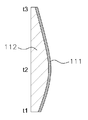
도 1은 본 발명의 실시예에 따른 CFRP 루프 패널에 적용되는 보강부재의 단면도이다. 1 is a cross-sectional view of a reinforcing member applied to a CFRP roof panel according to an embodiment of the present invention.
본 발명은 직물(woven fabric)로 형성되는 루프 패널(100)과 상기 루프 패널의 하부에 위치하며, 연속 탄소 섬유층(111)과 탄소 SMC층(112)으로 형성되는 보강 부재(110)를 포함하여 형성될 수 있다. The present invention includes a
상기 보강 부재(110)는 상기 탄소 SMC층(112) 위에 연속 탄소 섬유층(111)을 접합 또는 적층하여 형성될 수 있다.The reinforcing
상기 탄소 SMC(Sheet Molding Compound)층(112)은, 불포화 폴리에스테르 (Unsaturated Polyester; UP) 또는 비닐 에스테르(Vinyl Ester: VE)를 포함하여 형성될 수 있다.The carbon SMC (Sheet Molding Compound)
상기 연속 탄소 섬유층(111)은 연속 섬유 상태로 평직, 능직, 수자직 등의 직물 형태로 형성될 수 있는데, 질량에 비해서 얇고, 섬유가 넓어진 구조를 갖고 있어서 섬유의 두께 방향의 물결침이 작기 때문에 강도 및 강성을 증대시키면서도 경량화가 가능한 장점이 있다. The continuous
본 발명에서는 상기 탄소 SMC 층(112)에 연속 탄소 섬유층(111)을 보강하게 되는데, 이는 비연속 탄소 섬유를 이용하는 경우에는 연속 탄소 섬유를 이용하는 경우보다 강성이 낮으므로 보강 부재(110)의 두께는 커지고, 강성을 확보하기 위해서는 반드시 경량이 되지 않을 수 있기 때문이다. In the present invention, the continuous
위와 같이 보강 부재(110)는 연속 탄소 섬유층(111)을 보강 하여, 탄소 섬유의 특징의 하나인 높은 탄성률과 강도를 발현시킬 수 있고, 외부 충격에 대한 저항, 강성 및 강도를 경량으로 달성할 수 있다. 즉, 비연속 탄소 섬유로는 달성할 수 없는 경량 형성, 강성 및 충격 특성이 얻어지며, 더 나아가 변형 저항, 최대 하중, 변위량, 에너지 흡수도 증대될 수 있다. As described above, the reinforcing
상기 연속 탄소 섬유층(111)은 PAN(폴리아크릴니트릴)계 탄소 섬유, 핏치계 탄소 섬유중 어느 하나를 이용하여 형성할 수 있으며, PAN계의 탄소 섬유는 강도, 탄성률, 신도의 밸런스 상에서 직물을 만드는 데에 있어서 보다 바람직하다. The continuous
또한, 본 발명의 연속 탄소 섬유층(111)은 발명의 필요에 따라 탄소 섬유 이외에, 유리 섬유, 알루미나 섬유, 질화 규소 섬유 등의 무기 섬유, 아라미드계 섬유나 나일론 등의 유기 섬유를 첨가하여 형성할 수도 있다. The continuous
위와 같이 탄소 SMC층(112) 및 연속 탄소 섬유층(111)으로 형성되는 보강 부재(110)는 루프 패널(100)의 하부에 배치되어 루프 패널의 비틀림 강성, 굽힘 강성을 확보하게 된다. The reinforcing
한편, 상기 보강 부재(110)는, 그 양단 영역(t1, t3)보다 중간 영역(t2)의 두께가 더 두껍도록 형성되며, 그 일단 영역(t1)의 두께가 타단 영역(t3)보다 더 두껍도록 형성될 수 있다. On the other hand, the reinforcing
이는 차량의 운행 시 바람 등에 의한 양력을 가장 많이 받는 루프 패널의 하부에 보강 부재(100)를 두껍게 형성함으로써 굽힘 강성을 확보하기 위함이다. 도 1을 참조하면, 차량의 앞부분에 위치하는 부분이 t3이고, 차량의 뒷부분에 위치하는 부분이 t1이다. This is to secure the bending rigidity by forming the reinforcing
또한, 이와 같이 본 발명의 보강 부재(110)는 일정한 두께를 갖는 것이 아니라 각 영역에 따라 두께를 달리하여 형성함으로써 CFRP 루프 패널 전체의 경량화를 확보할 수 있다. As described above, the reinforcing
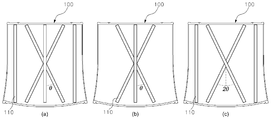
도 2는 본 발명의 실시예에 따른 CFRP 루프 패널의 구성도이고, 도 3은 본 발명의 실시예에 따른 CFRP 루프 패널의 보강 부재의 교차각에 따른 비틀림 강성을 나타낸 그래프이다. FIG. 2 is a view illustrating a configuration of a CFRP roof panel according to an embodiment of the present invention, and FIG. 3 is a graph illustrating a torsional stiffness according to an intersection angle of a reinforcing member of a CFRP roof panel according to an embodiment of the present invention.
도 2를 참조하면, CFRP 루프 패널을 하부에서 바라본 모습을 도시하고 있으며, 복수의 보강부재(110)가 배치되어 있음을 확인할 수 있다. Referring to FIG. 2, the CFRP roof panel is viewed from the bottom, and a plurality of reinforcing
상기 보강 부재(110)는 루프 패널(100)의 하부 양단을 지지하는 적어도 하나 이상의 보강 부재로 형성될 수 있는데, 도 2에서는 수직형으로 도시되는 보강 부재가 이의 예이며, 보강 부재(110)의 숫자가 증가할수록 당연히 비틀림 강성 및 굽힘 강성이 증대될 수 있을 것이다. The reinforcing
한편, 본 발명에서는 비틀림 강성 및 굽힘 강성을 더욱 증대시키기 위하여 루프 패널(100)의 하부 양단의 사선 방향으로 교차되는 적어도 한 쌍 이상의 보강 부재를 더 추가할 수 있다. In order to further increase the torsional rigidity and the bending rigidity of the present invention, at least one or more pairs of reinforcing members crossing in the oblique direction at both ends of the lower portion of the
본 발명에서 상기 한 쌍 이상의 보강 부재의 교차각(Θ)은 각각 0°초과 55°이하의 범위에서 결정되도록 형성될 수 있는데, 상기 교차각(Θ)은 20°내지 30°의 범위에서 형성되는 것이 더욱 바람직할 것이다.In the present invention, the crossing angle (?) Of the pair of the reinforcing members may be formed to be in a range of more than 0 ° and less than 55 °, and the crossing angle (?) Is formed in a range of 20 ° to 30 ° .
도 3을 참조하면, 상기 교차각(Θ)은 각각 0°초과 55°이하의 범위일 때 평균 이상의 비틀림 강성을 확보할 수 있으며, 특히 20°내지 30°의 범위에서 뛰어난 비틀림 강성을 확보함을 확인할 수 있다. Referring to FIG. 3, when the cross angle? Is in the range of more than 0 ° and less than 55 °, an average torsional rigidity can be ensured. In particular, excellent torsional rigidity is secured in the range of 20 ° to 30 ° Can be confirmed.
도 4는 본 발명의 실시예에 따른 CFRP 루프 패널 및 그 단면도인데, 도 4의 (b)는 도 4의 (a)에서 도시되는 CFRP 루프 패널을 A-A' 방향으로 자른 단면도 이다. FIG. 4 is a cross-sectional view of a CFRP roof panel according to an embodiment of the present invention, and FIG. 4 (b) is a cross-sectional view of the CFRP roof panel shown in FIG.
본 발명의 루프 패널(100)은 직물(woven fabric)로 형성될 수 있는데, 상기 루프 패널(100)은, 복수의 프리프레그(prepreg)를 적층하되, 섬유 배열 방향이 위로부터 0°/90°가 되도록 형성될 수 있다. The
상기 직물은 단층이어서 본 발명에서와 같이 섬유 배열 방향이 위로부터 0°/90°가 되도록 직교하는 방식으로 제작하면, 한 방향으로 배열하는 프리프레그를 적층한 경우보다 적은 매수로 루프 패널(100)을 구성할 수 있으므로 패널의 경량화를 확보할 수 있다. When the fabric is made of a single layer and is made to be orthogonal so that the direction of fiber arrangement is 0 ° / 90 ° from the top as in the present invention, the number of prepregs arranged in one direction is smaller than that of laminated prepregs, The weight of the panel can be secured.
본 발명에서는 루프 패널(100)이 직물(woven fabric)로만 형성되고, 단방향 연속섬유를 일정한 교차각으로 적층하고 고분자 섬유로 직조하여 제작되는 NCF 층 등의 복합체 층을 배제하고 형성되는 것이기 때문에 루프 패널의 프리폼 형상 등을 보다 자유롭게 형성할 수 있는 장점이 있다. In the present invention, since the
다만, 상기 루프 패널(100)은 직물로만 형성되므로, 적정한 비틀림 강성을 확보할 수 없고 스틸 사양 대비 차체의 비틀림 강성이 저하될 수 밖에 없다. However, since the
그러나, 전술한 바대로 본 발명에서는 상기 루프 패널(100)의 하부에 복수의 보강 부재(110)를 접합시킴으로써 비틀림 강성을 확보할 수 있다. However, as described above, in the present invention, the reinforcing
한편, 상기 프리프레그는 결합재를 강화섬유에 미리 함침시킨 시트(Sheet) 형태의 제품으로서 복합재료의 중간재료일 수 있으며, 여기서, 상기 강화섬유는 탄소섬유, 유리섬유, 아라미드 섬유 등을 적용할 수 있고, 상기 결합재는 에폭시 수지, 폴리에스터 수지 등 열경화성 또는 열가소성 수지를 이용할 수 있을 것이다. On the other hand, the prepreg may be an intermediate material of a composite material as a product in the form of a sheet impregnated with a binding material in advance in a reinforcing fiber, wherein the reinforcing fiber may be carbon fiber, glass fiber, aramid fiber, And a thermosetting or thermoplastic resin such as an epoxy resin or a polyester resin may be used as the binder.
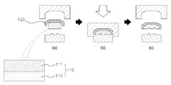
도 5는 본 발명의 실시예에 따른 루프 패널 프리폼을 형성하는 공정을 순서대로 나타낸 예시도이고, 도 6은 본 발명의 실시예에 따른 CFRP 루프 패널의 제조 공정을 순서대로 나타낸 예시도이다.FIG. 5 is a view illustrating a process of forming a roof panel preform according to an embodiment of the present invention in order; FIG. 6 is a view illustrating a process of fabricating a CFRP roof panel according to an embodiment of the present invention;
본 발명의 CFRP 루프 패널 제조방법은, 루프 패널의 프리폼을 형성하는 단계와, 프리폼과 보강 부재를 동시에 압축하여 일체 성형하는 단계로 형성될 수 있다.The CFRP roof panel manufacturing method of the present invention can be formed by a step of forming a preform of a roof panel and a step of integrally molding the preform and the reinforcing member at the same time.
여기서 상기 프리폼 형성단계는 도 5에서 도시한 바와 같이, i) 프리프레그(prepreg)를 적층하는 단계, ii) 상기 프리프레그를 가열하는 단계 및 iii) 상기 가열된 프리프레그를 압축 및 프리포밍하여 루프 패널의 프리폼을 형성하는 단계로 형성될 수 있다. As shown in FIG. 5, the preform forming step includes i) laminating a prepreg, ii) heating the prepreg, and iii) compressing and preforming the heated prepreg, And forming a preform of the panel.
상기 프리프레그의 적층 단계는, 도 5의 (a)에서 볼 수 있듯이 복수의 프리프레그(prepreg)를 적층하되, 섬유 배열 방향이 위로부터 0°/90°가 되도록 배치된다. 즉, 본 발명에서와 같이 그 섬유 배열 방향이 위로부터 0°/90°가 되도록 직교하는 방식으로 제작하면, 한 방향으로 배열하는 프리프레그를 적층한 경우보다 적은 매수로 루프 패널(100)을 구성할 수 있으므로 패널의 경량화 및 그 형상의 자유도를 확보할 수 있다는 것은 전술한 바 있다. As shown in FIG. 5 (a), a plurality of prepregs are stacked so that the fiber arrangement direction is 0 ° / 90 ° from the top. That is, if the fiber array is manufactured in such a manner that the direction of the fiber arrangement is orthogonal to 0 ° / 90 ° from the top as in the present invention, the number of the
한편, 도 6을 참조하면, 루프 패널의 프리폼(120) 및 탄소 SMC층에 연속 탄소 섬유층이 적층된 보강 부재(110)를 프레스에 하형에 올려두고, 프레스의 상형을 닫으며 소정의 온도와 압력을 가해 CFRP 루프 패널을 일체 성형하는 모습을 도시하고 있다. 6, a
이 때, 보강 부재의 열변형을 방지하기 위해 프레스에서 가해지는 온도는 250℃이하로 설정하는 것이 바람직하며, 또한 보강 부재의 압축 강도 등을 고려하여 프레스에서 가해지는 압력은 200Mpa 이하로 설정되는 것이 바람직할 것이다. In this case, in order to prevent thermal deformation of the reinforcing member, the temperature applied by the press is preferably set to 250 DEG C or less, and the pressure applied to the press in consideration of the compressive strength of the reinforcing member is set to 200 MPa or less Lt; / RTI >
이와 같이 본 발명에 의하면 루프 패널의 형상, 구조를 자유롭게 형성할 수 있으며, 루프 패널의 프리포밍 공정을 일체성형으로 단순화할 수 있다. 또한, 루프 패널의 비틀림 강성 및 굽힘 강성을 확보하여 루프 패널의 내구성이 확보될 수 있는 장점이 있다. As described above, according to the present invention, the shape and structure of the roof panel can be freely formed, and the preforming process of the roof panel can be simplified by integral molding. Further, there is an advantage that the durability of the roof panel can be ensured by securing the torsional rigidity and the bending rigidity of the roof panel.
이상 본 발명의 구체적 실시형태와 관련하여 본 발명을 설명하였으나 이는 예시에 불과하며 본 발명은 이에 제한되지 않는다. 본 발명이 속하는 기술분야에서 통상의 지식을 가진 자는 본 발명의 범위를 벗어나지 않고 설명된 실시형태를 변경 또는 변형할 수 있으며, 본 발명의 기술사상과 아래에 기재될 특허청구범위의 균등범위 내에서 다양한 수정 및 변형이 가능하다.
Although the present invention has been described in connection with the specific embodiments of the present invention, it is to be understood that the present invention is not limited thereto. It will be understood by those skilled in the art that various changes in form and details may be made therein without departing from the spirit and scope of the invention as defined by the appended claims and their equivalents. Various modifications and variations are possible.
100: 루프 패널
110: 보강 부재
111: 연속 탄소 섬유층
112: 탄소 SMC층
120: 루프 패널의 프리폼100: Loop panel
110: reinforcing member
111: continuous carbon fiber layer
112: Carbon SMC layer
120: Preform of the roof panel
Claims (12)
상기 루프 패널의 하부에 위치하며, 연속 탄소 섬유층과 탄소 SMC(Sheet Molding Compound)층으로 형성되는 보강 부재;를 포함하고,
상기 보강 부재는,
그 양단 영역(t1, t3)보다 중간 영역(t2)의 두께가 더 두껍도록 형성되는 것을 특징으로 하는 CFRP(Carbon Fiber Reinforced Plastic) 루프 패널.
A roof panel formed of a woven fabric; And
And a reinforcing member which is disposed below the roof panel and is formed of a continuous carbon fiber layer and a carbon SMC (Sheet Molding Compound) layer,
The reinforcing member
Is formed such that the thickness of the intermediate region (t2) is thicker than that of the both end regions (t1, t3) of the CFRP (Carbon Fiber Reinforced Plastic) roof panel.
상기 루프 패널의 하부에 위치하며, 연속 탄소 섬유층과 탄소 SMC(Sheet Molding Compound)층으로 형성되는 보강 부재;를 포함하고,
상기 보강 부재는,
그 일단 영역(t1)의 두께가 타단 영역(t3)보다 더 두껍도록 형성되는 것을 특징으로 하는 CFRP(Carbon Fiber Reinforced Plastic) 루프 패널.
A roof panel formed of a woven fabric; And
And a reinforcing member which is disposed below the roof panel and is formed of a continuous carbon fiber layer and a carbon SMC (Sheet Molding Compound) layer,
The reinforcing member
(Carbon fiber reinforced plastic) CFRP (Carbon Fiber Reinforced Plastic) panel characterized in that the thickness of the region t1 is thicker than that of the other end region (t3).
상기 보강 부재는,
상기 탄소 SMC(Sheet Molding Compound)층 위에 연속 탄소 섬유층을 접합하여 형성되는 것을 특징으로 하는 CFRP 루프 패널.
3. The method according to any one of claims 1 to 3,
The reinforcing member
Wherein the CFRP roof panel is formed by joining a continuous carbon fiber layer on the carbon SMC (Sheet Molding Compound) layer.
상기 보강 부재는,
상기 루프 패널의 하부 양단을 지지하는 적어도 하나 이상의 보강 부재로 형성되는 것을 특징으로 하는 CFRP 루프 패널.
3. The method according to any one of claims 1 to 3,
The reinforcing member
And at least one reinforcing member for supporting both ends of the lower portion of the roof panel.
상기 보강 부재는,
상기 루프 패널의 하부 양단의 사선 방향으로 교차되는 적어도 한 쌍 이상의 보강 부재를 더 포함하는 것을 특징으로 하는 CFRP 루프 패널.
5. The method of claim 4,
The reinforcing member
Further comprising at least one pair of reinforcing members crossing obliquely at both ends of the lower portion of the roof panel.
상기 한 쌍 이상의 보강 부재의 교차각(Θ)은 각각 0°초과 55°이하의 범위에서 결정되도록 형성되는 것을 특징으로 하는 CFRP 루프 패널.
6. The method of claim 5,
Wherein a crossing angle (?) Of the pair of reinforcing members is formed so as to be determined in a range of more than 0 ° and not more than 55 °.
상기 루프 패널은,
복수의 프리프레그(prepreg)를 적층하되, 그 섬유 배열 방향이 위로부터 0°/90°가 되도록 형성하는 것을 특징으로 하는 CFRP 루프 패널.
3. The method according to any one of claims 1 to 3,
The roof panel includes:
A CFRP loop panel comprising a plurality of prepregs stacked, the fiber arrangement direction of which is 0 ° / 90 ° from the top.
상기 탄소 SMC(Sheet Molding Compound)층은,
불포화 폴리에스테르 (Unsaturated Polyester; UP) 또는 비닐 에스테르(Vinyl Ester: VE)를 포함하여 형성되는 것을 특징으로 하는 CFRP 루프 패널.
3. The method according to any one of claims 1 to 3,
The carbon SMC (Sheet Molding Compound)
Characterized in that it is formed comprising an Unsaturated Polyester (UP) or a Vinyl Ester (VE).
상기 프리폼과 보강 부재를 동시에 압축하여 일체 성형하는 단계;를 포함하고,
상기 보강 부재는,
그 양단 영역(t1, t3)보다 중간 영역(t2)의 두께가 더 두껍도록 형성되는 것을 특징으로 하는 CFRP(Carbon Fiber Reinforced Plastic) 루프 패널 제조방법.
Forming a preform of the roof panel; And
And simultaneously compressing the preform and the reinforcing member to integrally mold the preform and the reinforcing member,
The reinforcing member
And the thickness of the intermediate region (t2) is made thicker than the both end regions (t1, t3) thereof.
상기 프리폼과 보강 부재를 동시에 압축하여 일체 성형하는 단계;를 포함하고,
상기 보강 부재는,
그 일단 영역(t1)의 두께가 타단 영역(t3)보다 더 두껍도록 형성되는 것을 특징으로 하는 CFRP(Carbon Fiber Reinforced Plastic) 루프 패널 제조방법.
Forming a preform of the roof panel; And
And simultaneously compressing the preform and the reinforcing member to integrally mold the preform and the reinforcing member,
The reinforcing member
Wherein the thickness of the first region t1 is greater than the thickness of the other region t3 of the carbon fiber reinforced plastic (CFRP) roof panel.
상기 프리폼 형성단계는,
프리프레그(prepreg)를 적층하는 단계;
상기 프리프레그를 가열하는 단계; 및
상기 가열된 프리프레그를 압축 및 프리포밍하여 루프 패널의 프리폼을 형성하는 단계; 를 포함하는 것을 특징으로 하는 CFRP 루프 패널 제조방법.
11. The method according to any one of claims 9 to 10,
In the preform forming step,
Laminating prepregs;
Heating the prepreg; And
Compressing and preforming the heated prepreg to form a preform of a roof panel; Wherein the CFRP roof panel comprises a plurality of panels.
상기 보강 부재는,
상기 루프 패널의 하부에 위치하며, 연속 탄소 섬유층과 탄소 SMC(Sheet Molding Compound)층으로 형성되는 것을 특징으로 하는 CFRP 루프 패널의 제조방법. 11. The method according to any one of claims 9 to 10,
The reinforcing member
Wherein the roof panel is formed of a continuous carbon fiber layer and a carbon SMC (Sheet Molding Compound) layer .
Priority Applications (1)
| Application Number | Priority Date | Filing Date | Title |
|---|---|---|---|
| KR1020160000815A KR101794844B1 (en) | 2016-01-05 | 2016-01-05 | Carbon Fiber Reinforced Plastic Roof-Panel |
Applications Claiming Priority (1)
| Application Number | Priority Date | Filing Date | Title |
|---|---|---|---|
| KR1020160000815A KR101794844B1 (en) | 2016-01-05 | 2016-01-05 | Carbon Fiber Reinforced Plastic Roof-Panel |
Publications (2)
| Publication Number | Publication Date |
|---|---|
| KR20170082163A KR20170082163A (en) | 2017-07-14 |
| KR101794844B1 true KR101794844B1 (en) | 2017-11-08 |
Family
ID=59358662
Family Applications (1)
| Application Number | Title | Priority Date | Filing Date |
|---|---|---|---|
| KR1020160000815A Active KR101794844B1 (en) | 2016-01-05 | 2016-01-05 | Carbon Fiber Reinforced Plastic Roof-Panel |
Country Status (1)
| Country | Link |
|---|---|
| KR (1) | KR101794844B1 (en) |
Citations (4)
| Publication number | Priority date | Publication date | Assignee | Title |
|---|---|---|---|---|
| JP2006082275A (en) * | 2004-09-14 | 2006-03-30 | Mitsubishi Engineering Plastics Corp | Long fiber reinforced thermoplastic resin exterior molding |
| JP2013147160A (en) * | 2012-01-19 | 2013-08-01 | Toyota Motor Corp | Body superstructure |
| WO2014034586A1 (en) * | 2012-08-27 | 2014-03-06 | 東レ株式会社 | Roof structure for vehicle |
| JP2015515390A (en) * | 2012-02-28 | 2015-05-28 | オートモビリ ランボルギーニ ソチエタ ペル アツイオニ | Method for producing carbon fiber article and article produced by this method |
-
2016
- 2016-01-05 KR KR1020160000815A patent/KR101794844B1/en active Active
Patent Citations (4)
| Publication number | Priority date | Publication date | Assignee | Title |
|---|---|---|---|---|
| JP2006082275A (en) * | 2004-09-14 | 2006-03-30 | Mitsubishi Engineering Plastics Corp | Long fiber reinforced thermoplastic resin exterior molding |
| JP2013147160A (en) * | 2012-01-19 | 2013-08-01 | Toyota Motor Corp | Body superstructure |
| JP2015515390A (en) * | 2012-02-28 | 2015-05-28 | オートモビリ ランボルギーニ ソチエタ ペル アツイオニ | Method for producing carbon fiber article and article produced by this method |
| WO2014034586A1 (en) * | 2012-08-27 | 2014-03-06 | 東レ株式会社 | Roof structure for vehicle |
Also Published As
| Publication number | Publication date |
|---|---|
| KR20170082163A (en) | 2017-07-14 |
Similar Documents
| Publication | Publication Date | Title |
|---|---|---|
| US10047910B2 (en) | Apparatus for fastening gas vessel and manufacturing method of the same | |
| US7651756B2 (en) | Resin infused transparent skin panel and method of making same | |
| JP4977696B2 (en) | Reinforcing beam, method for manufacturing the reinforcing beam, and fiber laminate | |
| JP6276230B2 (en) | Method for improving strength and rigidity of automobile body | |
| US9302445B2 (en) | Fiber-reinforced composite material | |
| US20160311467A1 (en) | I-beam with reinforced skin | |
| KR20160133605A (en) | Reinforcement member for the auto part and the auto part comprising the same | |
| KR101956131B1 (en) | Composite material for reinforcement and articles comprising the same | |
| CN106170389B (en) | Impact absorbing structure and vehicle outer panel member with the impact absorbing structure | |
| CN109562687B (en) | Working liquid container with reinforced structure | |
| JP2944967B2 (en) | High-speed vehicle outer wall structure and high-speed vehicle outer wall manufacturing method | |
| JP2920370B2 (en) | Bird-resistant structure at the head of high-speed vehicles | |
| KR101794844B1 (en) | Carbon Fiber Reinforced Plastic Roof-Panel | |
| KR20170070734A (en) | A composite for roof of an automaobile and a method for preparation thereof | |
| JP5064981B2 (en) | Fiber reinforced composite material | |
| JP2006200702A (en) | Shock absorbing member | |
| JP4328175B2 (en) | Fiber reinforced plastic vehicle hood | |
| US20210094244A1 (en) | Fiber-reinforced resin composite material and method of manufacturing fiber-reinforced resin composite material | |
| CN215730615U (en) | Display module | |
| KR101079452B1 (en) | Trailer made of fiber reinforced plastics | |
| JP2004339778A (en) | Door and manufacturing method thereof | |
| CN117460617A (en) | Body parts | |
| CN113724606A (en) | Display module | |
| KR20220147397A (en) | Composite pannel and method for manufacturing the same | |
| JP6731875B2 (en) | Fiber reinforced composite |
Legal Events
| Date | Code | Title | Description |
|---|---|---|---|
| A201 | Request for examination | ||
| PA0109 | Patent application |
St.27 status event code: A-0-1-A10-A12-nap-PA0109 |
|
| PA0201 | Request for examination |
St.27 status event code: A-1-2-D10-D11-exm-PA0201 |
|
| R18-X000 | Changes to party contact information recorded |
St.27 status event code: A-3-3-R10-R18-oth-X000 |
|
| D13-X000 | Search requested |
St.27 status event code: A-1-2-D10-D13-srh-X000 |
|
| D14-X000 | Search report completed |
St.27 status event code: A-1-2-D10-D14-srh-X000 |
|
| E902 | Notification of reason for refusal | ||
| PE0902 | Notice of grounds for rejection |
St.27 status event code: A-1-2-D10-D21-exm-PE0902 |
|
| P11-X000 | Amendment of application requested |
St.27 status event code: A-2-2-P10-P11-nap-X000 |
|
| P13-X000 | Application amended |
St.27 status event code: A-2-2-P10-P13-nap-X000 |
|
| PG1501 | Laying open of application |
St.27 status event code: A-1-1-Q10-Q12-nap-PG1501 |
|
| E701 | Decision to grant or registration of patent right | ||
| PE0701 | Decision of registration |
St.27 status event code: A-1-2-D10-D22-exm-PE0701 |
|
| GRNT | Written decision to grant | ||
| PR0701 | Registration of establishment |
St.27 status event code: A-2-4-F10-F11-exm-PR0701 |
|
| PR1002 | Payment of registration fee |
St.27 status event code: A-2-2-U10-U11-oth-PR1002 Fee payment year number: 1 |
|
| PG1601 | Publication of registration |
St.27 status event code: A-4-4-Q10-Q13-nap-PG1601 |
|
| R18-X000 | Changes to party contact information recorded |
St.27 status event code: A-5-5-R10-R18-oth-X000 |
|
| PR1001 | Payment of annual fee |
St.27 status event code: A-4-4-U10-U11-oth-PR1001 Fee payment year number: 4 |
|
| PR1001 | Payment of annual fee |
St.27 status event code: A-4-4-U10-U11-oth-PR1001 Fee payment year number: 5 |
|
| PR1001 | Payment of annual fee |
St.27 status event code: A-4-4-U10-U11-oth-PR1001 Fee payment year number: 6 |
|
| PR1001 | Payment of annual fee |
St.27 status event code: A-4-4-U10-U11-oth-PR1001 Fee payment year number: 7 |
|
| PR1001 | Payment of annual fee |
St.27 status event code: A-4-4-U10-U11-oth-PR1001 Fee payment year number: 8 |
|
| PR1001 | Payment of annual fee |
St.27 status event code: A-4-4-U10-U11-oth-PR1001 Fee payment year number: 9 |
|
| U11 | Full renewal or maintenance fee paid |
Free format text: ST27 STATUS EVENT CODE: A-4-4-U10-U11-OTH-PR1001 (AS PROVIDED BY THE NATIONAL OFFICE) Year of fee payment: 9 |