CN109562687B - Working liquid container with reinforced structure - Google Patents
Working liquid container with reinforced structure Download PDFInfo
- Publication number
- CN109562687B CN109562687B CN201780048154.XA CN201780048154A CN109562687B CN 109562687 B CN109562687 B CN 109562687B CN 201780048154 A CN201780048154 A CN 201780048154A CN 109562687 B CN109562687 B CN 109562687B
- Authority
- CN
- China
- Prior art keywords
- container
- reinforcement structure
- container wall
- reinforcing
- working liquid
- Prior art date
- Legal status (The legal status is an assumption and is not a legal conclusion. Google has not performed a legal analysis and makes no representation as to the accuracy of the status listed.)
- Active
Links
Images


Classifications
-
- B—PERFORMING OPERATIONS; TRANSPORTING
- B60—VEHICLES IN GENERAL
- B60K—ARRANGEMENT OR MOUNTING OF PROPULSION UNITS OR OF TRANSMISSIONS IN VEHICLES; ARRANGEMENT OR MOUNTING OF PLURAL DIVERSE PRIME-MOVERS IN VEHICLES; AUXILIARY DRIVES FOR VEHICLES; INSTRUMENTATION OR DASHBOARDS FOR VEHICLES; ARRANGEMENTS IN CONNECTION WITH COOLING, AIR INTAKE, GAS EXHAUST OR FUEL SUPPLY OF PROPULSION UNITS IN VEHICLES
- B60K15/00—Arrangement in connection with fuel supply of combustion engines or other fuel consuming energy converters, e.g. fuel cells; Mounting or construction of fuel tanks
- B60K15/03—Fuel tanks
- B60K15/03177—Fuel tanks made of non-metallic material, e.g. plastics, or of a combination of non-metallic and metallic material
-
- B—PERFORMING OPERATIONS; TRANSPORTING
- B60—VEHICLES IN GENERAL
- B60K—ARRANGEMENT OR MOUNTING OF PROPULSION UNITS OR OF TRANSMISSIONS IN VEHICLES; ARRANGEMENT OR MOUNTING OF PLURAL DIVERSE PRIME-MOVERS IN VEHICLES; AUXILIARY DRIVES FOR VEHICLES; INSTRUMENTATION OR DASHBOARDS FOR VEHICLES; ARRANGEMENTS IN CONNECTION WITH COOLING, AIR INTAKE, GAS EXHAUST OR FUEL SUPPLY OF PROPULSION UNITS IN VEHICLES
- B60K15/00—Arrangement in connection with fuel supply of combustion engines or other fuel consuming energy converters, e.g. fuel cells; Mounting or construction of fuel tanks
- B60K15/03—Fuel tanks
- B60K2015/03032—Manufacturing of fuel tanks
- B60K2015/03046—Manufacturing of fuel tanks made from more than one layer
-
- B—PERFORMING OPERATIONS; TRANSPORTING
- B60—VEHICLES IN GENERAL
- B60K—ARRANGEMENT OR MOUNTING OF PROPULSION UNITS OR OF TRANSMISSIONS IN VEHICLES; ARRANGEMENT OR MOUNTING OF PLURAL DIVERSE PRIME-MOVERS IN VEHICLES; AUXILIARY DRIVES FOR VEHICLES; INSTRUMENTATION OR DASHBOARDS FOR VEHICLES; ARRANGEMENTS IN CONNECTION WITH COOLING, AIR INTAKE, GAS EXHAUST OR FUEL SUPPLY OF PROPULSION UNITS IN VEHICLES
- B60K15/00—Arrangement in connection with fuel supply of combustion engines or other fuel consuming energy converters, e.g. fuel cells; Mounting or construction of fuel tanks
- B60K15/03—Fuel tanks
- B60K2015/03328—Arrangements or special measures related to fuel tanks or fuel handling
- B60K2015/03453—Arrangements or special measures related to fuel tanks or fuel handling for fixing or mounting parts of the fuel tank together
-
- B—PERFORMING OPERATIONS; TRANSPORTING
- B60—VEHICLES IN GENERAL
- B60K—ARRANGEMENT OR MOUNTING OF PROPULSION UNITS OR OF TRANSMISSIONS IN VEHICLES; ARRANGEMENT OR MOUNTING OF PLURAL DIVERSE PRIME-MOVERS IN VEHICLES; AUXILIARY DRIVES FOR VEHICLES; INSTRUMENTATION OR DASHBOARDS FOR VEHICLES; ARRANGEMENTS IN CONNECTION WITH COOLING, AIR INTAKE, GAS EXHAUST OR FUEL SUPPLY OF PROPULSION UNITS IN VEHICLES
- B60K15/00—Arrangement in connection with fuel supply of combustion engines or other fuel consuming energy converters, e.g. fuel cells; Mounting or construction of fuel tanks
- B60K15/03—Fuel tanks
- B60K2015/03486—Fuel tanks characterised by the materials the tank or parts thereof are essentially made from
Landscapes
- Engineering & Computer Science (AREA)
- Life Sciences & Earth Sciences (AREA)
- Sustainable Development (AREA)
- Sustainable Energy (AREA)
- Chemical & Material Sciences (AREA)
- Combustion & Propulsion (AREA)
- Transportation (AREA)
- Mechanical Engineering (AREA)
- Cooling, Air Intake And Gas Exhaust, And Fuel Tank Arrangements In Propulsion Units (AREA)
- Filling Or Discharging Of Gas Storage Vessels (AREA)
Abstract
Description
技术领域technical field
本发明涉及一种具有加强结构的工作液体容器。The present invention relates to a working liquid container with a reinforced structure.
背景技术Background technique
在本发明的意义上,由热塑性材料制成的工作液体容器尤其是,但不限于用于机动车的燃料箱、抹水箱、油箱,补充液体箱或机动车的添加剂箱。最初提到的类型的容器通常通过挤压吹塑制造,其中HDPE(高密度聚乙烯的简称)特别适用于生产挤压吹塑成形的容器。In the sense of the present invention, a working fluid container made of thermoplastic material is in particular, but not limited to, a fuel tank, a wiper tank, a fuel tank, a supplementary fluid tank or an additive tank for a motor vehicle. Containers of the first mentioned type are usually manufactured by extrusion blow moulding, with HDPE (short for high density polyethylene) being particularly suitable for producing extrusion blow moulded containers.
在具有内燃机的机动车中,当热量施加到工作液体容器,特别是燃料箱时,工作液体,例如燃料也被加热,使得工作液体的蒸汽压力增加并且工作液体容器受到相应的内部压力,由此燃料箱变形。In a motor vehicle with an internal combustion engine, when heat is applied to the working fluid container, in particular the fuel tank, the working fluid, eg fuel, is also heated, so that the vapour pressure of the working fluid increases and the working fluid container experiences a corresponding internal pressure, whereby Deformed fuel tank.
为了对燃料箱形式的工作液体容器进行通风,把其与用于过滤燃料蒸汽的燃料蒸汽过滤器流体连接。燃料蒸汽过滤器例如可以形成为活性炭过滤器。在内燃机运行期间借助于吸入空气冲刷活性炭过滤器,从而能够把结合在活性炭中的燃料蒸汽导入内燃机中。In order to ventilate the working fluid container in the form of a fuel tank, it is fluidly connected to a fuel vapor filter for filtering fuel vapors. The fuel vapor filter can be formed, for example, as an activated carbon filter. During operation of the internal combustion engine, the activated carbon filter is flushed by means of intake air, so that the fuel vapors bound in the activated carbon can be introduced into the internal combustion engine.
在混合动力机动车中,还存在由内燃机的运行时间减少引起的另一个问题。由于内燃机的运行时间减少,流体连接到燃料箱的活性炭过滤器相应地较少被吹扫,从而较少的结合在活性炭中的燃料蒸汽会被吹走。这会导致,在混合动力机动车中活性炭过滤器的尺寸必须较大。此外,通过活性炭过滤器使燃料箱通风基于燃料箱内部的压降使其它的燃料转移到汽相中,从而有利的是使燃料箱更硬和/或耐压。因为那时燃料箱可以通过可控阀与活性炭过滤器流体分离,由此活性炭过滤器装载较少的燃料蒸汽。In hybrid vehicles, there is another problem caused by the reduced operating time of the internal combustion engine. Due to the reduced operating time of the internal combustion engine, the activated carbon filter fluidly connected to the fuel tank is correspondingly less purged, so that less fuel vapors bound in the activated carbon are blown away. As a result, the size of the activated carbon filter must be larger in hybrid vehicles. In addition, venting the fuel tank through an activated carbon filter transfers additional fuel into the vapor phase based on the pressure drop inside the fuel tank, thereby advantageously making the fuel tank stiffer and/or pressure resistant. Because then the fuel tank can be fluidly separated from the charcoal filter by a controllable valve, whereby the charcoal filter is loaded with less fuel vapor.
因此,希望增加工作液体容器,特别是燃料箱的以及在那里尤其是用于混合动力机动车的燃料箱的抗压性。用于混合动力机动车的燃料箱优选应该能够承受高达400毫巴或更高的过压和约150毫巴或更高的低压。Therefore, it is desirable to increase the pressure resistance of working fluid containers, in particular of fuel tanks, and there, in particular of fuel tanks for hybrid vehicles. Fuel tanks for hybrid vehicles should preferably be able to withstand overpressures of up to 400 mbar or more and low pressures of about 150 mbar or more.
从现有技术中已知了,借助于布置在两个彼此对置的工作液体容器壁之间的加强元件来加强工作液体容器,其中加强元件连接到工作液体容器壁。由DE 10 2013 012 687A1已知了一种相应的工作液体容器。该工作液体容器在过压和低压下都具有增加的结构稳定性。然而,这种加强的缺点是,不再能完全自由地使用工作液体容器内部空间。It is known from the prior art to reinforce the working fluid container by means of reinforcing elements arranged between two mutually opposite working fluid container walls, wherein the reinforcing elements are connected to the working fluid container walls. A corresponding working fluid container is known from DE 10 2013 012 687 A1. The working fluid container has increased structural stability under both overpressure and underpressure. However, this reinforcement has the disadvantage that the interior space of the working fluid container can no longer be used completely freely.
发明内容SUMMARY OF THE INVENTION
本发明的目的在于,提供一种工作液体容器,该工作液体容器能承受增大的过压和低压,并且该工作液体容器在压力加载时具有减小的变形,其中同时应该保证,工作液体容器内部空间在不具有或具有减小的限制的情况下都保持可用。The object of the present invention is to provide a working fluid container which can withstand increased overpressures and low pressures and which exhibits reduced deformation during pressure loading, wherein at the same time it should be ensured that the working fluid container Interior space remains available with no or reduced restrictions.
本发明的目的通过具有权利要求1所述特征的工作液体容器实现。在权利要求1的从属权利要求中描述了工作液体容器的有利的设计方案。The object of the invention is achieved by a working fluid container having the features of
更具体地,本发明的目的通过一种用于机动车的工作液体容器实现,该工作液体容器具有界定了工作液体容器内部空间的容器壁,其中,所述工作液体容器的特征在于,该工作液体容器包括第一纤维增强的加强结构和第二纤维增强的加强结构,其中第一加强结构连接到容器壁的、朝向工作液体容器内部空间的内表面,以及第二加强结构连接到容器壁的、背向工作液体容器内部空间的外表面,以及其中容器壁至少部分地以夹层状方式如此布置在第一加强结构和第二加强结构之间,使得第一加强结构和第二加强结构布置为至少部分重叠。More specifically, the object of the invention is achieved by a working fluid container for a motor vehicle, which working fluid container has a container wall delimiting the interior space of the working fluid container, wherein the working fluid container is characterized in that the working fluid container is The liquid container includes a first fiber-reinforced reinforcement structure and a second fiber-reinforced reinforcement structure, wherein the first reinforcement structure is connected to the inner surface of the container wall facing the interior space of the working liquid container, and the second reinforcement structure is connected to the container wall. , the outer surface facing away from the interior space of the working fluid container, and wherein the container wall is arranged at least partially in a sandwich-like manner between the first reinforcement structure and the second reinforcement structure such that the first reinforcement structure and the second reinforcement structure are arranged as at least partially overlap.
根据本发明的工作液体容器具有多方面的优点。由于第一和第二加强结构之间的容器壁的夹层状布置,容器壁在两个弯曲方向上具有增加的抗弯强度,从而根据本发明的工作液体容器无论在工作液体容器内部空间中是过压还是低压时(相对于环境压力)都具有减小的变形。因此,根据本发明的工作液体容器既可以承受更大的过压也能承受更大的低压。The working liquid container according to the present invention has various advantages. Due to the sandwich-like arrangement of the container wall between the first and second reinforcement structures, the container wall has increased flexural strength in both bending directions, so that the working fluid container according to the present invention is in the interior space of the working fluid container regardless of There is reduced deformation (relative to ambient pressure) at both overpressure and underpressure. Therefore, the working fluid container according to the present invention can withstand both a greater overpressure and a greater low pressure.
由于根据本发明的工作液体容器的增加的刚度,该工作液体容器在过压负荷下和/或在低压负荷下具有明显减小的变形。由此允许根据本发明的工作液体容器能够以相对于车身部件和/或相对于其它机动车部件减小的距离安装在机动车中。由此可改进地利用供安装工作液体容器使用的结构空间,从而在机动车中预定的结构空间中,根据本发明的工作液体容器具有增大的容积。Due to the increased stiffness of the working fluid container according to the invention, the working fluid container has a significantly reduced deformation under overpressure loads and/or under low pressure loads. This allows the working fluid container according to the invention to be installed in a motor vehicle at a reduced distance relative to the body part and/or relative to other motor vehicle parts. As a result, the installation space for installing the working fluid container can be used in an improved manner, so that the working fluid container according to the invention has an increased volume in a predetermined installation space in the motor vehicle.
此外,根据本发明的工作液体容器的优点还在于,其内部空间可以在没有或至少较少限制的情况下使用,因为在工作液体容器内部空间中不必布置加固支柱。Furthermore, the working fluid container according to the invention has the advantage that its interior space can be used without or at least less restrictive, since reinforcement struts do not have to be arranged in the interior space of the working fluid container.
根据本发明的工作液体容器尽管具有增大的刚度,然而其具有相对于现有技术中已知的工作液体容器相比更小的重量。根据本发明的工作液体容器可以通过加强结构局部地和/或负载相关地加强。此外,根据本发明的工作液体容器可以成本低廉地制造。Despite the increased stiffness, the working fluid container according to the invention has a lower weight compared to the working fluid containers known from the prior art. The working fluid container according to the invention can be reinforced locally and/or load-dependently by means of reinforcement structures. Furthermore, the working fluid container according to the invention can be produced cost-effectively.
根据本发明的工作液体容器的另一个优点是这样的特性,即工作液体容器制造(由吹塑工艺或通过注塑工艺)之后在其冷却时,其容器壁具有减小的拉伸/扭曲,因为容器壁不是仅在一侧上,也就是说在其外表面上或其内表面上设有加强结构,而是既在外表面上也在内表面上分别设置有加强结构。Another advantage of the working fluid container according to the present invention is the property that, after the working fluid container is manufactured (either by a blow moulding process or by an injection moulding process), when it cools down, its container walls have reduced stretching/twisting, because The container wall is not provided with reinforcement structures only on one side, that is to say on its outer surface or its inner surface, but is provided with reinforcement structures, respectively, both on the outer surface and on the inner surface.
对工作液体容器形成为燃料箱,尤其是用于汽油燃料的燃料箱的情况来说,根据本发明的工作液体容器具有用于碳氢化合物的突出的屏障特性,因为加强结构不损坏容器壁的屏障层(例如,EVOH层),并且不限制其功能性。In the case where the working fluid container is formed as a fuel tank, especially for gasoline fuels, the working fluid container according to the invention has outstanding barrier properties for hydrocarbons, since the reinforcement structure does not damage the walls of the container. Barrier layer (eg, EVOH layer), and does not limit its functionality.
特征—根据该特征容器壁至少部分地以夹层状方式如此布置在第一加强结构和第二加强结构之间,使得第一加强结构和第二加强结构布置为至少部分重叠,等同于特征—在与第一加强结构和/或第二加强结构的重叠区域中,容器壁的面法线穿过第一加强结构和第二加强结构。这意味着,在容器壁的俯视图中,即在与容器壁的面法线平行的视线方向上第一加强结构和第二加强结构重叠。也就是说,容器壁的面法线在容器壁的、与第一加强结构和与第二加强结构连接的区域中,既贯穿第一加强结构也贯穿第二加强结构。Feature - according to which the container wall is arranged at least partially in a sandwich-like manner between the first reinforcement structure and the second reinforcement structure such that the first reinforcement structure and the second reinforcement structure are arranged to at least partially overlap, equivalent to the feature - in In the overlapping region with the first reinforcement structure and/or the second reinforcement structure, the surface normal of the container wall passes through the first reinforcement structure and the second reinforcement structure. This means that the first reinforcement structure and the second reinforcement structure overlap in a plan view of the container wall, ie in a viewing direction parallel to the surface normal of the container wall. That is to say, the surface normal of the container wall in the region of the container wall that is connected to the first reinforcement structure and to the second reinforcement structure penetrates both the first reinforcement structure and the second reinforcement structure.
在容器壁由于内部过压导致变形时,第二加强结构吸收拉力和第一加强结构吸收压力。在容器壁由于内部低压导致变形时,第一加强结构吸收拉力和第二加强结构吸收压力。The second reinforcement structure absorbs tensile forces and the first reinforcement structure absorbs pressure when the container wall is deformed due to internal overpressure. The first reinforcing structure absorbs the tensile force and the second reinforcing structure absorbs the pressure when the container wall is deformed due to the internal low pressure.
工作液体容器优选地由热塑性塑料形成。在工作液体容器被形成为燃料箱的情况下,可以形成由材料层系统组成的容器壁,该材料层系统包括HDPE层的形式的内层、LDPE层形式的增附剂层、EVOH层形式的屏障层、LDPE层形式的另一个增附剂层、以及另一个HDPE层或再生利用材料层(Recyklatschicht)形式的外层。The working fluid container is preferably formed of thermoplastic. In the case where the working liquid container is formed as a fuel tank, it is possible to form the container wall consisting of a material layer system comprising an inner layer in the form of an HDPE layer, an adhesion promoter layer in the form of an LDPE layer, an EVOH layer in the form of an inner layer. A barrier layer, a further adhesion promoter layer in the form of an LDPE layer, and an outer layer in the form of a further HDPE layer or a recycled material layer.
第一和第二加强结构的纤维增强借助于增强纤维进行,增强纤维也可以称为纤维材料。纤维材料优选地包括玻璃纤维和/或碳纤维和/或聚合物纤维和/或芳族聚酰胺纤维和/或天然纤维(例如,亚麻纤维)和/或其他合适的纤维材料。The fiber reinforcement of the first and second reinforcement structures is carried out by means of reinforcement fibers, which may also be referred to as fiber materials. The fibre material preferably comprises glass fibres and/or carbon fibres and/or polymer fibres and/or aramid fibres and/or natural fibres (eg flax fibres) and/or other suitable fibre materials.
第一和第二加强结构优选具有热塑性或热固性基质或基质材料,纤维材料嵌入其中。The first and second reinforcing structures preferably have a thermoplastic or thermosetting matrix or matrix material in which the fibrous material is embedded.
纤维增强的加强结构可以吸收拉力,因此可以称为抗拉的加强结构或加强装置。优选加强结构也可以吸收压力,因此可以称为抗拉的-和/或耐压的加强结构或加强装置。Fiber-reinforced reinforcement structures can absorb tensile forces and can therefore be referred to as tensile reinforcement structures or reinforcements. Preferably, the reinforcement structure can also absorb compressive forces and can therefore be referred to as tensile- and/or compressive-resistant reinforcement structures or reinforcements.
当然,根据本发明的工作液体容器还可以包括多个第一纤维增强加强结构和多个第二纤维增强加强结构,其中第一加强结构被连接到所述容器壁的内表面并且第二加强结构被连接到容器壁的外表面。Of course, the working fluid container according to the present invention may also comprise a plurality of first fiber-reinforced reinforcement structures and a plurality of second fiber-reinforced reinforcement structures, wherein the first reinforcement structures are connected to the inner surface of the container wall and the second reinforcement structures is attached to the outer surface of the container wall.
一或多个第一加强结构与容器壁的内表面的连接优选以整个表面的方式进行,即一或多个第一加强结构的、与容器壁的内表面对置的整个连接面与容器壁的内表面连接。该连接优选地材料锁合地进行,例如通过焊接。一或多个第二加强结构与容器壁的外表面的连接优选以整个表面的方式进行,即一或多个第二加强结构的、与容器壁的外表面对置的整个连接面与容器壁的外表面连接。该连接优选地材料锁合地进行,例如通过焊接。The connection of the one or more first reinforcement structures to the inner surface of the container wall preferably takes place over the entire surface, ie the entire connection surface of the one or more first reinforcement structures that is opposite the inner surface of the container wall and the container wall the inner surface of the connection. The connection is preferably made in a cohesive manner, for example by welding. The connection of the one or more second reinforcement structures to the outer surface of the container wall is preferably carried out over the entire surface, ie the entire connection surface of the one or more second reinforcement structures that is opposite the outer surface of the container wall and the container wall external surface connection. The connection is preferably made in a cohesive manner, for example by welding.
此外,一或多个第一加强结构与容器壁的内表面的连接优选也能够以部分表面的方式进行。此外,一或多个第二加强结构与容器壁的外表面的连接优选也能够以部分表面的方式进行。Furthermore, the connection of the one or more first reinforcement structures to the inner surface of the container wall can preferably also take place in a part-surface manner. Furthermore, the connection of the one or more second reinforcement structures to the outer surface of the container wall can preferably also take place in a partial surface manner.
优选如此形成工作液体容器,容器壁以夹层状方式如此布置在第一加强结构和第二加强结构之间,使得在容器壁的俯视图中观察第一加强结构和第二加强结构相对彼此布置齐平地延伸。The working fluid container is preferably formed in such a way that the container wall is arranged in a sandwich-like manner between the first reinforcement structure and the second reinforcement structure in such a way that the first reinforcement structure and the second reinforcement structure are arranged flush with each other when viewed in a plan view of the container wall extend.
相应形成的工作液体容器具有进一步增加的刚度,使得该工作液体容器能承受升高的过压和低压并且在加载过压和加载低压时具有较小的变形。尽管工作液体容器的重量轻,但仍实现了这些优点。The correspondingly formed working fluid container has a further increased rigidity, so that the working fluid container can withstand increased overpressure and low pressure and has less deformation when overpressure and underpressure are applied. These advantages are achieved despite the low weight of the working fluid container.
当容器壁布置在由x轴和垂直于该x轴的y轴限定的平面内时,则特征—根据该特征在容器壁的俯视图中观察第一加强结构和第二加强结构相对彼此布置为齐平地延伸,等同于特征—第一加强结构沿x方向以及沿y方向具有和第二加强结构相同的延展。When the container wall is arranged in a plane defined by the x-axis and the y-axis perpendicular to the x-axis, then the feature - according to which the first reinforcement structure and the second reinforcement structure are arranged flush with respect to each other when viewed in a plan view of the container wall Flat extension, equivalent to feature - the first reinforcement structure has the same extension in the x-direction as well as in the y-direction as the second reinforcement structure.
因此,第一加强结构和第二加强结构的分界边缘彼此齐平地延伸。Thus, the boundary edges of the first reinforcement structure and the second reinforcement structure extend flush with each other.
更优选地,所述工作液体容器如此形成,使得第一加强结构设计为纤维增强的、抗拉的第一带,和/或第二加强结构设计为纤维增强的、抗拉的第二带。More preferably, the working fluid container is formed such that the first reinforcement structure is designed as a fiber-reinforced, tensile-resistant first belt, and/or the second reinforcement structure is designed as a fiber-reinforced, tensile-resistant second belt.
优选地,第一带形成为抗拉的和抗压的带,使得拉力和压力都可以通过第一带传递。优选地,第二带形成为抗拉的和抗压的带,使得拉力和压力都可以通过第二带传递。Preferably, the first belt is formed as a tensile and compressive belt such that both tensile and compressive forces can be transmitted through the first belt. Preferably, the second belt is formed as a tensile and compressive belt such that both tensile and compressive forces can be transmitted through the second belt.
因此,相应形成的工作液体容器可以以特别简单的方式加强或加固,从而可以有针对性地改善由工作液体容器的几何形状引起的变形特性。由于带可以有针对性地在工作液体容器的区域内与一或多个容器壁的内表面和外表面连接,所述区域在加载过压和/或加载低压时将承受大的变形,所以这些区域不借助于带—其也可以称为加固带或增强带—增强。Accordingly, the correspondingly formed working fluid container can be reinforced or reinforced in a particularly simple manner, so that the deformation properties caused by the geometry of the working fluid container can be improved in a targeted manner. Since the belt can be connected in a targeted manner to the inner and outer surfaces of one or more container walls in the region of the working fluid container, which is subject to large deformations when subjected to overpressure and/or underpressure, these The regions are not reinforced by means of tapes, which may also be referred to as reinforcing tapes or reinforcing tapes.
纤维增强的抗拉的和/或抗压的带可以具有热塑性或热固性塑料形成的材料基质,其中嵌入了形式为玻璃纤维和/或碳纤维和/或聚合物纤维和/或芳族聚酰胺纤维和/或天然纤维的纤维材料。The fiber-reinforced tensile and/or compressive tape can have a material matrix of thermoplastic or thermosetting plastics, in which are embedded in the form of glass fibers and/or carbon fibers and/or polymer fibers and/or aramid fibers and / or fibrous material of natural fibers.
优选地,第一带的增强纤维的取向平行于第一带的纵向延伸方向。进一步优选地,第二带的增强纤维的取向平行于第二带的纵向延伸方向。Preferably, the orientation of the reinforcing fibers of the first belt is parallel to the longitudinal extension of the first belt. Further preferably, the orientation of the reinforcing fibers of the second belt is parallel to the longitudinal extension of the second belt.
增强纤维相对于带的纵向延伸方向的平行取向意味着,增强纤维相对于带的纵向延伸方向基本上平行的取向。The parallel orientation of the reinforcing fibers with respect to the longitudinal extension of the belt means an orientation in which the reinforcing fibers are substantially parallel with respect to the longitudinal extension of the belt.
增强纤维可以是玻璃纤维和/或碳纤维和/或聚合物纤维和/或芳族聚酰胺纤维和/或天然纤维和/或其他合适的增强纤维。The reinforcing fibers may be glass fibers and/or carbon fibers and/or polymer fibers and/or aramid fibers and/or natural fibers and/or other suitable reinforcing fibers.
根据另一有利的设计方案,工作液体容器如此形成,使得所述第一加强结构形成为第一有机板,和/或第二加强结构形成为第二有机板。According to a further advantageous configuration, the working fluid container is formed such that the first reinforcement structure is formed as a first organic plate and/or the second reinforcement structure is formed as a second organic plate.
相应地形成的工作液体容器的优点在于:相应形成为有机板的加强结构能够改进地吸收多方向的拉力和/或压力。这是因为增强纤维以多方向布置在各个有机板中。优选地,增强纤维彼此垂直地布置在有机板中。The advantage of a correspondingly formed working fluid container is that the reinforcing structure correspondingly formed as an organic sheet can absorb multidirectional tensile and/or compressive forces in an improved manner. This is because the reinforcing fibers are arranged in each organic plate in multiple directions. Preferably, the reinforcing fibers are arranged in the organic plate perpendicular to each other.
有机板是纤维复合材料,因此是纤维基质半成品。它们由纤维编织物或纤维铺设物组成,它们嵌入通常热塑性的塑料基质中。经常使用的纤维材料是玻璃、芳纶和碳(炭)。在编织和铺设时,纤维也可以彼此垂直地延伸。Organic boards are fiber composites and therefore fiber matrix semi-finished products. They consist of fiber braids or fiber lays, which are embedded in a generally thermoplastic plastic matrix. Commonly used fiber materials are glass, aramid and carbon (charcoal). The fibers can also extend perpendicular to each other when weaving and laying.
更优选地,所述工作液体容器如此形成,使得所述第一加强结构在容器壁的内表面上附接在两个相对彼此间隔开的附接区域上,和/或第二加强结构在容器壁的外表面上附接在两个相对彼此间隔开的附接区域上。More preferably, the working fluid container is formed such that the first reinforcement structure is attached on the inner surface of the container wall in two relatively spaced apart attachment areas, and/or the second reinforcement structure is attached to the container. The outer surface of the wall is attached on two attachment areas spaced relative to each other.
相应地形成的工作液体容器能特别简单且快速地制造,因为相应的加强结构仅需要在两个相对彼此间隔开的区域或锚定点处连接到容器壁。加强结构还可以吸收由于容器壁的变形引起的拉力,并进而抵消容器壁的变形。A correspondingly formed working fluid container can be produced particularly simply and quickly, since the corresponding reinforcement structure only needs to be connected to the container wall at two areas or anchor points that are spaced apart from each other. The reinforcement structure can also absorb the tensile force caused by the deformation of the container wall, and thus counteract the deformation of the container wall.
当第一和第二加强结构分别形成为第一和第二抗拉的和纤维增强的带时,所述带的增强纤维优选在两个相对彼此间隔开的附接区域的连接线的延伸方向上延伸。When the first and second reinforcing structures are formed as first and second tensile and fiber-reinforced tapes, respectively, the reinforcing fibers of the tapes are preferably in the direction of extension of the connecting line of the two spaced-apart attachment regions relative to each other up extension.
当然同样可行的是,把第一加强结构在容器壁的内表面上附接在两个以上的相对彼此间隔开的附接区域上,和/或第二加强结构在容器壁的外表面上附接在两个以上的相对彼此间隔开的附接区域上。It is of course also possible to attach the first reinforcement structure on the inner surface of the container wall to two or more attachment areas spaced apart from each other and/or attach the second reinforcement structure to the outer surface of the container wall Attached to two or more attachment areas spaced relative to each other.
优选如此形成工作液体容器,使得所述第一加强结构沿着连接线连接到容器壁的内表面上,所述连接线具有至少一个延伸部分,所述延伸部分在第一加强结构内部垂直于增强纤维的纤维方向延伸。此外,优选如此形成工作液体容器,使得所述第二加强结构沿着连接线连接到容器壁的外表面上,所述连接线具有至少一个延伸部分,所述延伸部分在第二加强结构内部垂直于增强纤维的纤维方向延伸。The working fluid container is preferably formed such that the first reinforcement structure is connected to the inner surface of the container wall along a connecting line, the connection line having at least one extension which is perpendicular to the reinforcement inside the first reinforcement structure The fiber direction of the fiber extends. Furthermore, the working fluid container is preferably formed such that the second reinforcement structure is connected to the outer surface of the container wall along a connecting line, the connection line having at least one extension that is perpendicular inside the second reinforcement structure Extends in the fiber direction of the reinforcing fibers.
例如,加强结构可以通过Z字形线连接到容器壁。For example, the reinforcement structure may be connected to the vessel wall by zigzag lines.
优选如此形成工作液体容器,使得第一加强结构在工作液体容器内部沿周向/环绕地布置,和/或第二加强结构在工作液体容器外部沿周向布置。The working fluid container is preferably formed such that the first reinforcement structure is arranged circumferentially/circumferentially inside the working fluid container and/or the second reinforcement structure is arranged circumferentially outside the working fluid container.
相应地形成的工作液体容器具有进一步增加的刚度,使得该工作液体容器能够承受增加的过压和低压并且在加载过压和加载低压时具有较小的变形。The correspondingly formed working fluid container has a further increased stiffness, so that the working fluid container can withstand increased overpressure and low pressure and has less deformation when overpressure and underpressure are applied.
根据另一有利的设计方案,工作液体容器具有至少两个第一纤维增强的加强结构,该第一纤维增强的加强结构分别与所述容器壁的、朝向工作液体容器内部空间的内表面连接,其中两个第一加强结构如此相对彼此交叉地布置,使得它们的增强纤维相对彼此成角度地,优选相对彼此垂直地延伸。优选至少两个第一加强结构在接触区域中彼此连接,在所述接触区域中,两个第一加强结构彼此重叠。According to another advantageous design, the working fluid container has at least two first fiber-reinforced reinforcement structures, which are respectively connected to the inner surfaces of the container wall facing the interior space of the working fluid container, The two first reinforcing structures are arranged so as to cross each other in such a way that their reinforcing fibers extend at an angle to each other, preferably perpendicular to each other. Preferably at least two first reinforcement structures are connected to each other in a contact region in which the two first reinforcement structures overlap each other.
更优选地,工作液体容器具有至少两个第二纤维增强的加强结构,其分别与所述容器壁的、背向工作液体容器内部空间的外表面连接,其中两个第二加强结构如此相对彼此交叉地布置,使得它们的增强纤维相对彼此成角度地,优选相对彼此垂直地延伸。优选至少两个第二加强结构在接触区域中彼此连接,在所述接触区域中,两个第二加强结构彼此重叠More preferably, the working fluid container has at least two second fiber-reinforced reinforcement structures, which are respectively connected to the outer surface of the container wall facing away from the interior space of the working fluid container, wherein the two second reinforcement structures are thus opposite each other. Arranged crosswise such that their reinforcing fibers extend at an angle to each other, preferably perpendicular to each other. Preferably at least two second reinforcement structures are connected to each other in the contact region in which the two second reinforcement structures overlap each other
工作液体容器的上两个实施方案还具有增加的刚度,从而该工作液体容器能承受增加的过压和低压并且在加载过压和加载低压时具有较小的变形。因为加强结构可以吸收具有不同的、优选垂直的力分量的拉力和/或压力。The last two embodiments of the working fluid container also have increased stiffness so that the working fluid container can withstand increased overpressure and low pressure and have less deformation when loaded with overpressure and loaded with low pressure. Because the reinforcement structure can absorb tensile and/or compressive forces with different, preferably vertical, force components.
当然,在一或多个容器壁的俯视图中观察,与容器壁连接的第一加强结构和第二加强结构可以重叠地,优选相对彼此齐平地布置。Of course, the first reinforcement structure and the second reinforcement structure connected to the container wall may be arranged overlapping, preferably flush with respect to each other, viewed in a plan view of one or more container walls.
优选如此形成工作液体容器,使得第一加强结构和/或第二加强结构以材料锁合的方式连接到容器壁。The working fluid container is preferably formed in such a way that the first reinforcement structure and/or the second reinforcement structure is connected to the container wall in a cohesive manner.
例如,具有热塑性塑料的加强结构能与由焊接技术兼容的热塑性塑料形成的结构材料锁合地连接。例如,加强结构可以具有包括HDPE或LDPE的或者由HDPE或LDPE形成的基质材料,该基质材料能与包括HDPE或由HDPE形成的容器壁焊接。For example, a reinforcing structure with thermoplastic can be materially connected to a structure formed from a thermoplastic compatible with welding technology. For example, the reinforcement structure may have a matrix material comprising or formed of HDPE or LDPE that can be welded to a vessel wall comprising or formed of HDPE.
优选加强结构可以与一或多个容器壁在所谓的第一热度中连接,其中加强结构被贴靠到仍然热塑性的容器壁上并必要时压紧在该容器壁上,从而加强结构焊接至容器壁。Preferably, the reinforcement structure can be connected to one or more container walls in a so-called first heat, wherein the reinforcement structure is placed against the still thermoplastic container wall and optionally pressed against it, so that the reinforcement structure is welded to the container wall.
然而,还可能的是,该加强结构和/或容器壁在工作液体容器冷却后被加热并随后贴靠到容器壁上且必要时压紧在该容器壁上。However, it is also possible for the reinforcement structure and/or the container wall to be heated after cooling of the working fluid container and then to abut and possibly press against the container wall.
加强结构与一或多个容器壁的材料锁合的连接还借助于加强结构与一或多个容器壁的粘和实现。The cohesive connection of the reinforcing structure to the one or more container walls is also achieved by means of the adhesive bonding of the reinforcing structure to the one or more container walls.
根据工作液体容器的另一可行的实施方案,第一加强结构通过布置在所述第一加强结构和所述容器壁的内表面之间的增附剂层与容器壁连接。此外优选第二加强结构通过布置在第二加强结构和容器壁的外表面之间的增附剂层与容器壁连接。According to another possible embodiment of the working fluid container, the first reinforcement structure is connected to the container wall by an adhesion promoter layer arranged between the first reinforcement structure and the inner surface of the container wall. Furthermore, preferably the second reinforcement structure is connected to the container wall by means of an adhesion promoter layer arranged between the second reinforcement structure and the outer surface of the container wall.
相应地形成的工作液体容器的优点在于,容器壁和加强结构(其基质材料)的材料不一定需要在焊接技术上彼此相容。因此,在选择用于加强结构的基质材料方面存在更大的自由度。The advantage of a correspondingly formed working fluid container is that the materials of the container wall and the reinforcement structure (the matrix material thereof) do not necessarily need to be compatible with each other in welding technology. Thus, there is greater freedom in choosing the matrix material for the reinforcement structure.
根据工作液体容器的另一有利的设计方案,如此设计该工作液体容器,使得第一加强结构借助于穿过所述第一加强结构的铆接连接与容器壁连接。此外优选的是,第二加强结构借助于穿过所述第二加强结构的铆接连接与容器壁连接。According to another advantageous configuration of the working fluid container, the working fluid container is designed such that the first reinforcement structure is connected to the container wall by means of a riveted connection through the first reinforcement structure. It is also preferred that the second reinforcement structure is connected to the container wall by means of a riveted connection through the second reinforcement structure.
相应地形成的工作液体容器的优点在于,容器壁和加强结构(其基质材料)的材料不一定需要在焊接技术上彼此相容。因此,在选择用于加强结构的基质材料方面存在更大的自由度。为了把加强结构与容器壁铆接,加强结构优选具有供铆钉穿过的贯通开口,其中铆钉由一种材料制成,这种材料能够与容器壁的材料,特别是容器壁的外层焊接。The advantage of a correspondingly formed working fluid container is that the materials of the container wall and the reinforcement structure (the matrix material thereof) do not necessarily need to be compatible with each other in welding technology. Thus, there is greater freedom in choosing the matrix material for the reinforcement structure. For riveting the reinforcement structure to the container wall, the reinforcement structure preferably has through openings through which the rivets are made of a material which can be welded to the material of the container wall, in particular to the outer layer of the container wall.
根据工作液体容器的另一有利的设计方案,第一加强结构具有至少一个第一连接销,该连接销朝向容器壁的内表面且具有第一底切部,其中第一连接销穿入到容器壁中,从而第一底切部没入容器壁中,且第一加强结构与容器壁形状锁合地连接。此外,优选第二加强结构具有至少一个第二连接销,该连接销朝向容器壁的外表面且具有第二底切部,其中第二连接销穿入到容器壁中,从而第二底切部没入容器壁中,且第二加强结构与容器壁形状锁合地连接。According to a further advantageous configuration of the working fluid container, the first reinforcement structure has at least one first connecting pin which faces the inner surface of the container wall and has a first undercut, wherein the first connecting pin penetrates into the container into the wall, so that the first undercut is submerged in the container wall, and the first reinforcement structure is positively connected to the container wall. Furthermore, it is preferred that the second reinforcement structure has at least one second connecting pin facing the outer surface of the container wall and having a second undercut, wherein the second connecting pin penetrates into the container wall so that the second undercut Submerged into the container wall, and the second reinforcement structure is positively connected to the container wall.
相应形成的工作液体容器还具有以下优点:容器壁和加强结构的材料不需要在焊接技术上彼此相容。此外,确保了加强结构在容器壁上的可靠连接。A correspondingly formed working fluid container also has the advantage that the materials of the container wall and the reinforcement structure do not need to be compatible with each other in welding technology. Furthermore, a reliable connection of the reinforcement structure to the container wall is ensured.
加强结构优选具有多个具有底切部的连接销,所述底切部分别在与容器壁的连接状态中没入该容器壁中。例如,连接销能够根据尼龙搭扣连接的方式形成为钩形。The reinforcement structure preferably has a plurality of connecting pins with undercuts, which in each case sink into the container wall in the connected state to the container wall. For example, the connecting pin can be formed into a hook shape according to the way of velcro connection.
例如,加强结构的基质材料可以是热固性塑料或包括这种材料,而容器壁,特别是容器壁的外层,由热塑性材料形成。For example, the matrix material of the reinforcing structure may be or comprise a thermoset plastic, while the container wall, in particular the outer layer of the container wall, is formed from a thermoplastic material.
附图说明Description of drawings
下面从阐述的实施例中得到本发明的其它优点、细节和特征。在此具体示出:Further advantages, details and features of the invention emerge from the illustrated embodiments below. Specifically shown here:
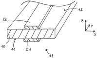
图1:根据本发明的工作液体容器的透视图;Figure 1 : a perspective view of a working liquid container according to the invention;
图2:根据本发明的工作液体容器的容器壁的横戴面图;Figure 2: A cross-sectional view of the container wall of the working liquid container according to the present invention;
图3A:是根据本发明的工作液体容器的备选实施方案的容器壁的横戴面图;3A: is a cross-sectional view of the container wall of an alternative embodiment of the working fluid container according to the present invention;
图3B:在图3A中示出的容器壁的示意性透视图;Figure 3B: a schematic perspective view of the container wall shown in Figure 3A;
图4:根据本发明的工作液体容器的另一个备选实施方案的容器壁的横戴面图;Figure 4: Cross-sectional view of the container wall of another alternative embodiment of the working fluid container according to the present invention;
图5A:根据本发明的工作液体容器的示意性横戴面图;Figure 5A: A schematic cross-sectional view of a working liquid container according to the present invention;
图5B:在图5A中环绕的区域的细部视图;以及Fig. 5B: A detailed view of the area encircled in Fig. 5A; and
图6:根据本发明的另一个实施方案的工作液体容器的容器壁的横戴面图。Figure 6: A cross-sectional view of the container wall of a working fluid container according to another embodiment of the present invention.
在以下描述中,相同的附图标记表示相同的构件或相同的特征,因此相对于一附图进行的、关于构件的描述也适用于其他附图,从而避免了重复的描述。此外,结合一实施方案已经描述的各个特征也可以在其他实施例中单独使用。In the following description, the same reference numerals denote the same components or the same features, so that the description of the components with respect to one drawing also applies to the other drawings, so as to avoid repeated descriptions. Furthermore, various features that have been described in connection with one embodiment can also be used alone in other embodiments.
具体实施方式Detailed ways
图1以示意性透视图示出了根据本发明的工作液体容器1。工作液体容器1具有界定工作液体容器内部空间13的容器壁10。可以看出,在示出的实施例中,工作液体容器1包括两个第二加强结构22,该第二加强结构在示出的实施例中形成为第二抗拉带22。在此,第二抗拉带22连接到容器壁10的背离工作液体容器内部空间13的外表面12。从图1还可以看出,第二抗拉带22布置为彼此交叉,从而在附图中未示出的抗拉带22的增强纤维相对彼此垂直地延伸。因为第二抗拉带22的增强纤维平行于第二抗拉带22的纵向延伸方向延伸。然而从图2中不能清楚看出,工作液体容器1还具有布置在工作液体容器1内部的第一加强结构21。Figure 1 shows a working
图2示出了根据本发明的工作液体容器1的容器壁10的示意性横戴面图。可以看出,工作液体容器1具有第一纤维增强的加强结构21和第二纤维增强的加强结构22。同样在图2所示的实施例中,加强结构21形成为抗拉带21、22。第一加强结构21与容器壁10的朝向工作液体容器内部空间13的内表面11连接,以及第二加强结构22与容器壁10的背向工作液体容器内部空间13的外表面12连接。容器壁10如此分段地以夹层状方式布置在第一加强结构11和第二加强结构12之间,使得第一加强结构11和第二加强结构12布置为至少部分地重叠。FIG. 2 shows a schematic cross-sectional view of the
特征—根据该特征容器壁10至少部分地以夹层状方式如此布置在第一加强结构21和第二加强结构22之间,使得第一加强结构21和第二加强结构22布置为至少部分重叠,等同于特征—在与第一加强结构21和/或第二加强结构22的重叠区域中,容器壁10的面法线N穿过第一加强结构21和第二加强结构22。从图2可以看出,在与面法线N平行的视线方向上,第一加强结构21和第二加强结构22重叠,也就是说,容器壁10的面法线N既贯穿第一加强结构21也贯穿第二加强结构22。Feature - according to this feature the
图3A示出了处于改进形式的工作液体容器1的容器壁10的示意性横戴面图。在图3B中,以示意性透视图示出了图3A中所示的容器壁10。从图3A和3B可以看出,容器壁10以夹层状方式如此布置在第一加强结构11和第二加强结构12之间,使得在容器壁10的俯视图中观察,第一加强结构21和第二加强结构22彼此齐平地延伸。因此,在俯视图中,第一加强结构21和第二加强结构22的相应的分界边缘同样彼此齐平地朝着工作液体容器壁10定向。Figure 3A shows a schematic cross-sectional view of the
从图3B中可以看出,容器壁10布置在由x轴和y轴限定的平面内。因此,特征—根据该特征在容器壁10的俯视图中观察,第一加强结21和第二加强结构22相对彼此齐平地延伸,等同于特征—第一加强结构沿x方向以及沿y方向具有和第二加强结构22相同的延展。As can be seen in Figure 3B, the
图4示出了根据另一实施方案的工作液体容器1的容器壁10的横截面。可以看出,工作液体容器1具有凹部。所述第一加强结构21在凹部的区域中被连接到容器壁10的内表面11,以及第二加强结构22既在凹部的区域中也在凹部外部的区域中被连接到容器壁10的外表面12。可以看出,容器壁10的面法线N在凹部的侧沿的区域中既穿过第一加强结构21也穿过第二加强结构22。Figure 4 shows a cross section of the
图5A示意性地示出了根据本发明的工作液体容器1的横截面。显示出,工作液体容器1受到内部过压P的作用。在图5A中上部示出的容器壁10与第一加强结构21和第二加强结构22连接。在图5B中放大示出了第一加强结构21与容器壁10以及第二加强结构22与容器壁10的接触区域。Figure 5A schematically shows a cross section of the working
从图5B可以看出,在加载内部压力时,也就是说与环境压力相比工作液体容器内部空间13内部存在过压时,第二加强结构22承受拉力负荷(参见在第二加强结构22的区域中彼此离开指向的箭头),以及第一加强结构21受到压力负荷(参见在第一加强结构21的区域中朝向彼此指向的箭头)。As can be seen from FIG. 5B , when the internal pressure is loaded, that is, when there is an overpressure in the
另一方面,当工作液体容器内部空间13具有比所述工作液体容器1的环境压力小的内部压力时,第二加强结构22受到压力负荷,相反第一加强结构21将受到拉力负荷。On the other hand, when the
在图6中示意性地示出了根据另一实施方案的工作液体容器1的工作液体容器壁10的剖面。可以看出,第一加强结构21和/或第二加强结构22具有多个连接销30,连接销分别具有底切部31。相应的连接销30在此穿透到容器壁10中,使得相应的底切部31没入容器壁10中,以及加强结构21、22与容器壁10形状锁合地连接。A cross-section of a working
附图标记列表List of reference signs
1 工作液体容器/燃料箱1 Working fluid container/fuel tank
10 容器壁10 Container Wall
11 内表面(容器壁)11 Inner surface (container wall)
12 外表面(容器壁)12 Outer surface (container wall)
13 工作液体容器内部空间13 Internal space of working liquid container
21 第一加强结构/第一抗拉带21 First Reinforcement Structure/First Tensile Strap
22 第二加强结构/第二抗拉带22 Secondary Reinforcement Structure/Second Tensile Strap
30 连接销30 Connecting pins
31 (连接销的)底切部31 Undercut (for connecting pin)
N (容器壁的)法线向量/法线方向N (of the container wall) normal vector / normal direction
P (在工作液体容器中)内部压力P (in the working fluid container) internal pressure
Claims (13)
Applications Claiming Priority (3)
| Application Number | Priority Date | Filing Date | Title |
|---|---|---|---|
| DE102016209544.7 | 2016-06-01 | ||
| DE102016209544.7A DE102016209544A1 (en) | 2016-06-01 | 2016-06-01 | Operating fluid tank with stiffening structure |
| PCT/EP2017/062279 WO2017207324A1 (en) | 2016-06-01 | 2017-05-22 | Fuel tank having a stiffening structure |
Publications (2)
| Publication Number | Publication Date |
|---|---|
| CN109562687A CN109562687A (en) | 2019-04-02 |
| CN109562687B true CN109562687B (en) | 2020-01-14 |
Family
ID=58873792
Family Applications (1)
| Application Number | Title | Priority Date | Filing Date |
|---|---|---|---|
| CN201780048154.XA Active CN109562687B (en) | 2016-06-01 | 2017-05-22 | Working liquid container with reinforced structure |
Country Status (7)
| Country | Link |
|---|---|
| US (1) | US11104221B2 (en) |
| EP (1) | EP3463960B1 (en) |
| JP (1) | JP6541900B1 (en) |
| KR (2) | KR102112462B1 (en) |
| CN (1) | CN109562687B (en) |
| DE (1) | DE102016209544A1 (en) |
| WO (1) | WO2017207324A1 (en) |
Families Citing this family (5)
| Publication number | Priority date | Publication date | Assignee | Title |
|---|---|---|---|---|
| DE102018102264B4 (en) * | 2018-02-01 | 2022-08-18 | Kautex Textron Gmbh & Co. Kg | Process for producing a plastic component and device for carrying out the process |
| JP7037247B2 (en) * | 2018-02-22 | 2022-03-16 | 本田技研工業株式会社 | Fuel tank |
| CN110217098A (en) * | 2019-06-23 | 2019-09-10 | 亚普汽车部件股份有限公司 | A kind of storage tank being provided with stiffener assembly and its production method |
| DE102019125403A1 (en) | 2019-09-20 | 2021-03-25 | Kautex Textron Gmbh & Co. Kg | PLASTIC CONTAINERS FOR MOTOR VEHICLES WITH AT LEAST ONE REINFORCEMENT STRUCTURE |
| DE102021108564B4 (en) * | 2021-04-07 | 2026-04-30 | Dr. Ing. H.C. F. Porsche Aktiengesellschaft | Motor vehicle component |
Citations (4)
| Publication number | Priority date | Publication date | Assignee | Title |
|---|---|---|---|---|
| CN102341260A (en) * | 2009-03-19 | 2012-02-01 | 考特克斯·特克斯罗恩有限公司及两合公司 | Plastic fuel tank |
| WO2013174461A1 (en) * | 2012-05-22 | 2013-11-28 | Kautex Textron Gmbh & Co. Kg | Tank made of thermoplastic material, in particular fuel tank or auxiliary fluid tank for a motor vehicle |
| WO2013174460A1 (en) * | 2012-05-22 | 2013-11-28 | Kautex Textron Gmbh & Co. Kg | Fuel tank or secondary fluid tank, consisting of thermoplastic, for a motor vehicle and method for prodcucing such fuel tank |
| CN105073471A (en) * | 2013-03-22 | 2015-11-18 | 考特克斯·特克斯罗恩有限公司及两合公司 | working fluid container |
Family Cites Families (19)
| Publication number | Priority date | Publication date | Assignee | Title |
|---|---|---|---|---|
| US3251500A (en) * | 1962-07-18 | 1966-05-17 | White Consolidated Ind Inc | Reinforced plastic tank and bracket mounting assembly |
| US4171999A (en) * | 1976-12-01 | 1979-10-23 | Allen John D | Method of fabricating a tank by joining wall sections with fiber reinforced joiner panels |
| US4552281A (en) * | 1984-06-29 | 1985-11-12 | Owens-Corning Fiberglas Corporation | Glass fiber reinforced resin tank with particular joint structure |
| DE69321610T2 (en) | 1993-01-21 | 1999-03-04 | United Technologies Corp., Hartford, Conn. | PRESSURE RESISTANT FUEL TANK PANELS |
| JPH11288991A (en) * | 1998-04-03 | 1999-10-19 | Shinko Electric Co Ltd | Load port |
| DE10009305A1 (en) * | 2000-02-22 | 2001-09-06 | Mannesmann Ag | Steel pipe used for transport of fluids under high pressure, has outer corrosion-proof protective sheath including plastic layer and crack stopper zone formed by wrapping bandage made of fiber material, around pipe |
| JP4180550B2 (en) * | 2004-08-30 | 2008-11-12 | 富士重工業株式会社 | Method for producing cryogenic composite pressure vessel |
| FR2879122B1 (en) * | 2004-12-15 | 2008-10-03 | Inergy Automotive Systems Res | PROCESS FOR THE MANUFACTURE OF A PLASTIC FUEL TANK HAVING IMPROVED FLOWING RESISTANCE |
| KR20090037768A (en) | 2007-10-12 | 2009-04-16 | 오은영 | Sandwich Panel |
| WO2010144501A1 (en) * | 2009-06-12 | 2010-12-16 | Material Engineering and Technical Support Services Corporation | Containment systems |
| DE102009032221A1 (en) * | 2009-07-08 | 2011-01-13 | Daimler Ag | Tank recess for a motor vehicle |
| DE102009039888A1 (en) | 2009-09-03 | 2011-03-10 | Volkswagen Ag | Plastic pressure vessel and process for its manufacture |
| BR112012031838B1 (en) * | 2010-06-15 | 2020-12-08 | Shaw Development, Llc | head unit and combination |
| DE102010044584A1 (en) * | 2010-09-07 | 2012-03-08 | Kautex Textron Gmbh & Co. Kg | Fuel tank made of thermoplastic material |
| JP5929079B2 (en) * | 2011-09-30 | 2016-06-01 | コベルコ建機株式会社 | Tank reinforcement structure |
| JP5934023B2 (en) * | 2012-05-16 | 2016-06-15 | 宝栄工業株式会社 | Fuel tank |
| DE102013012687A1 (en) | 2013-07-31 | 2015-02-05 | Kautex Textron Gmbh & Co. Kg | Operating fluid tank with stiffening element |
| CN104385610B (en) * | 2014-10-11 | 2017-07-04 | 亚普汽车部件股份有限公司 | A kind of forming method of three-dimensional many wall plastic hollow casings |
| JP2016168899A (en) * | 2015-03-12 | 2016-09-23 | 株式会社Fts | Tank holding band of fuel tank for automobile |
-
2016
- 2016-06-01 DE DE102016209544.7A patent/DE102016209544A1/en not_active Ceased
-
2017
- 2017-05-22 KR KR1020197023818A patent/KR102112462B1/en active Active
- 2017-05-22 US US16/306,897 patent/US11104221B2/en active Active
- 2017-05-22 CN CN201780048154.XA patent/CN109562687B/en active Active
- 2017-05-22 WO PCT/EP2017/062279 patent/WO2017207324A1/en not_active Ceased
- 2017-05-22 JP JP2018563515A patent/JP6541900B1/en active Active
- 2017-05-22 EP EP17726892.7A patent/EP3463960B1/en active Active
- 2017-05-22 KR KR1020187037946A patent/KR20190011289A/en not_active Ceased
Patent Citations (4)
| Publication number | Priority date | Publication date | Assignee | Title |
|---|---|---|---|---|
| CN102341260A (en) * | 2009-03-19 | 2012-02-01 | 考特克斯·特克斯罗恩有限公司及两合公司 | Plastic fuel tank |
| WO2013174461A1 (en) * | 2012-05-22 | 2013-11-28 | Kautex Textron Gmbh & Co. Kg | Tank made of thermoplastic material, in particular fuel tank or auxiliary fluid tank for a motor vehicle |
| WO2013174460A1 (en) * | 2012-05-22 | 2013-11-28 | Kautex Textron Gmbh & Co. Kg | Fuel tank or secondary fluid tank, consisting of thermoplastic, for a motor vehicle and method for prodcucing such fuel tank |
| CN105073471A (en) * | 2013-03-22 | 2015-11-18 | 考特克斯·特克斯罗恩有限公司及两合公司 | working fluid container |
Also Published As
| Publication number | Publication date |
|---|---|
| EP3463960B1 (en) | 2020-06-03 |
| DE102016209544A1 (en) | 2017-12-07 |
| JP6541900B1 (en) | 2019-07-10 |
| KR20190011289A (en) | 2019-02-01 |
| EP3463960A1 (en) | 2019-04-10 |
| WO2017207324A1 (en) | 2017-12-07 |
| KR20190097329A (en) | 2019-08-20 |
| JP2019521029A (en) | 2019-07-25 |
| US11104221B2 (en) | 2021-08-31 |
| CN109562687A (en) | 2019-04-02 |
| US20190263255A1 (en) | 2019-08-29 |
| KR102112462B1 (en) | 2020-05-18 |
Similar Documents
| Publication | Publication Date | Title |
|---|---|---|
| CN109562687B (en) | Working liquid container with reinforced structure | |
| CN103325963B (en) | Battery pack case assembly for vehicles using a plastic composite and method for manufacturing the same | |
| US7784856B2 (en) | Dynamic load bearing composite floor pan for an automotive vehicle | |
| EP2849932B1 (en) | Over-molding of load-bearing composite structures | |
| CN102341260B (en) | plastic fuel container | |
| US9759282B2 (en) | Air spring | |
| KR100971873B1 (en) | Integrated composite body for transportation vehicle and its manufacturing method | |
| CN110395320A (en) | Composite car bottom structure for vehicle | |
| US20190389516A1 (en) | Truck, deck gate for truck and method for manufacturing thereof | |
| US20180281711A1 (en) | Hybrid bumper beam for a vehicle and method for manufacturing the same | |
| KR20160133605A (en) | Reinforcement member for the auto part and the auto part comprising the same | |
| KR20130054362A (en) | Fuel tank made of thermoplastic material | |
| CN104441686A (en) | Carbon fiber composite upper crossbeam of automobile radiator and forming method of upper crossbeam | |
| US20130065469A1 (en) | Large tow carbon fiber composite with improved flexural property and surface property | |
| US11396329B2 (en) | Fiber-reinforced resin composite and manufacturing method of fiber-reinforced resin composite | |
| JP5036381B2 (en) | Fiber reinforced composite material | |
| JP5064981B2 (en) | Fiber reinforced composite material | |
| US20210094244A1 (en) | Fiber-reinforced resin composite material and method of manufacturing fiber-reinforced resin composite material | |
| CN108068895B (en) | Integral part of a motor vehicle frame | |
| US12011990B2 (en) | Plastic tank for motor vehicles having at least one reinforcing structure | |
| CN107685775A (en) | Automobile water tank upper beam made of carbon fiber reinforcing plate and its manufacture method | |
| US20190111633A1 (en) | Bonding of thermoplastic components to a thermoset component | |
| US12091169B2 (en) | Three-dimensional textile preforms and composite parts comprising textile preforms | |
| KR101794844B1 (en) | Carbon Fiber Reinforced Plastic Roof-Panel | |
| KR102819326B1 (en) | Stack frame for fuel cell and method thereof |
Legal Events
| Date | Code | Title | Description |
|---|---|---|---|
| PB01 | Publication | ||
| PB01 | Publication | ||
| SE01 | Entry into force of request for substantive examination | ||
| SE01 | Entry into force of request for substantive examination | ||
| GR01 | Patent grant | ||
| GR01 | Patent grant |