KR101214041B1 - Led drive circuit, led illumination fixture, led illumination device, and led illumination system - Google Patents
Led drive circuit, led illumination fixture, led illumination device, and led illumination system Download PDFInfo
- Publication number
- KR101214041B1 KR101214041B1 KR1020110004864A KR20110004864A KR101214041B1 KR 101214041 B1 KR101214041 B1 KR 101214041B1 KR 1020110004864 A KR1020110004864 A KR 1020110004864A KR 20110004864 A KR20110004864 A KR 20110004864A KR 101214041 B1 KR101214041 B1 KR 101214041B1
- Authority
- KR
- South Korea
- Prior art keywords
- led
- current
- voltage
- circuit
- extraction
- Prior art date
- Legal status (The legal status is an assumption and is not a legal conclusion. Google has not performed a legal analysis and makes no representation as to the accuracy of the status listed.)
- Expired - Fee Related
Links
Images


Classifications
-
- H—ELECTRICITY
- H05—ELECTRIC TECHNIQUES NOT OTHERWISE PROVIDED FOR
- H05B—ELECTRIC HEATING; ELECTRIC LIGHT SOURCES NOT OTHERWISE PROVIDED FOR; CIRCUIT ARRANGEMENTS FOR ELECTRIC LIGHT SOURCES, IN GENERAL
- H05B45/00—Circuit arrangements for operating light-emitting diodes [LED]
- H05B45/30—Driver circuits
- H05B45/37—Converter circuits
-
- F—MECHANICAL ENGINEERING; LIGHTING; HEATING; WEAPONS; BLASTING
- F21—LIGHTING
- F21K—NON-ELECTRIC LIGHT SOURCES USING LUMINESCENCE; LIGHT SOURCES USING ELECTROCHEMILUMINESCENCE; LIGHT SOURCES USING CHARGES OF COMBUSTIBLE MATERIAL; LIGHT SOURCES USING SEMICONDUCTOR DEVICES AS LIGHT-GENERATING ELEMENTS; LIGHT SOURCES NOT OTHERWISE PROVIDED FOR
- F21K9/00—Light sources using semiconductor devices as light-generating elements, e.g. using light-emitting diodes [LED] or lasers
- F21K9/20—Light sources comprising attachment means
- F21K9/23—Retrofit light sources for lighting devices with a single fitting for each light source, e.g. for substitution of incandescent lamps with bayonet or threaded fittings
- F21K9/238—Arrangement or mounting of circuit elements integrated in the light source
-
- F—MECHANICAL ENGINEERING; LIGHTING; HEATING; WEAPONS; BLASTING
- F21—LIGHTING
- F21Y—INDEXING SCHEME ASSOCIATED WITH SUBCLASSES F21K, F21L, F21S and F21V, RELATING TO THE FORM OR THE KIND OF THE LIGHT SOURCES OR OF THE COLOUR OF THE LIGHT EMITTED
- F21Y2115/00—Light-generating elements of semiconductor light sources
- F21Y2115/10—Light-emitting diodes [LED]
-
- Y—GENERAL TAGGING OF NEW TECHNOLOGICAL DEVELOPMENTS; GENERAL TAGGING OF CROSS-SECTIONAL TECHNOLOGIES SPANNING OVER SEVERAL SECTIONS OF THE IPC; TECHNICAL SUBJECTS COVERED BY FORMER USPC CROSS-REFERENCE ART COLLECTIONS [XRACs] AND DIGESTS
- Y02—TECHNOLOGIES OR APPLICATIONS FOR MITIGATION OR ADAPTATION AGAINST CLIMATE CHANGE
- Y02B—CLIMATE CHANGE MITIGATION TECHNOLOGIES RELATED TO BUILDINGS, e.g. HOUSING, HOUSE APPLIANCES OR RELATED END-USER APPLICATIONS
- Y02B20/00—Energy efficient lighting technologies, e.g. halogen lamps or gas discharge lamps
- Y02B20/30—Semiconductor lamps, e.g. solid state lamps [SSL] light emitting diodes [LED] or organic LED [OLED]
Landscapes
- Engineering & Computer Science (AREA)
- Physics & Mathematics (AREA)
- Microelectronics & Electronic Packaging (AREA)
- Optics & Photonics (AREA)
- General Engineering & Computer Science (AREA)
- Circuit Arrangement For Electric Light Sources In General (AREA)
- Led Devices (AREA)
Abstract
LED 구동 회로는 위상 제어식 조광기에 접속가능하고, 교류 전압을 입력해서 LED를 구동한다. 상기 LED 구동 회로에는 상기 위상 제어식 조광기의 출력 전압의 에지를 검출하는 에지 검출기와, LED 구동 전류를 LED에 공급하기 위한 전류 공급 라인으로부터 전류를 추출하는 전류 추출기가 구비되고, 상기 전류 추출기에 의해 상기 전류 공급 라인으로부터 추출되는 전류값은 상기 에지 검출기의 검출 결과에 따라 가변된다.The LED driving circuit is connectable to a phase controlled dimmer and inputs an alternating voltage to drive the LED. The LED driving circuit includes an edge detector for detecting the edge of the output voltage of the phase controlled dimmer, and a current extractor for extracting current from a current supply line for supplying the LED driving current to the LED. The current value extracted from the current supply line varies according to the detection result of the edge detector.

Description
본 발명은 LED(Light Emitting Diode)를 구동하는 LED 구동 회로뿐만 아니라, LED를 광원으로서 갖는 LED 조명등 기구, LED 조명 기기, 및 LED 조명 시스템에 관한 것이다.The present invention relates not only to an LED driving circuit for driving a light emitting diode (LED), but also to an LED lighting device having a LED as a light source, an LED lighting device, and an LED lighting system.
LED는 저소비 전류 및 장수명 등의 특징을 갖고, 표시 장치뿐만 아니라 조명 기구 등에도 그 용도가 확대되고 있다. LED 조명 기구에서는 소망의 조도를 얻기 위해 복수개의 LED를 종종 사용한다.LEDs have characteristics such as low current consumption and long life, and their use is expanding not only to display devices but also to lighting fixtures. LED lighting fixtures often use multiple LEDs to achieve the desired illuminance.
일반적인 조명 기구는 상용 전원(AC100V~240V)을 통상 사용하고, 백열등 또는 다른 조명 기구 대신에 LED 조명등 기구를 사용할 경우에 LED 조명등 기구도 일반적인 조명등 기구와 같이 상용 전원(AC100V~240V)을 사용하도록 구성되는 것이 바람직하다.General lighting fixtures use commercial power (AC100V ~ 240V) normally, and when LED lighting fixtures are used instead of incandescent or other lighting fixtures, LED lighting fixtures are configured to use commercial power supply (AC100V ~ 240V) like general lighting fixtures. It is preferable to be.
또한, 백열등을 조광 제어에 적용할 경우에 스위칭 소자(일반적으로는 사이리스터 소자나 트라이액 소자)를 교류 전원 전압의 어떤 위상각에서 온함으로써 백열등으로의 전원 공급을 하나의 볼륨 소자로 용이하게 조광 제어할 수 있는 위상 제어식 조광기(일반적으로 백열 라이트 컨트롤이라 언급됨)가 이용되고 있다. 그러나, 저와트의 백열등에 위상 제어식 조광기에 접속되면 플리커링(flickering) 또는 점멸이 발생되어 정상 조광이 불가능하다는 것이 알려져 있다.In addition, when the incandescent lamp is applied to the dimming control, the switching element (typically a thyristor element or triac element) is turned on at a certain phase angle of the AC power supply voltage so that the power supply to the incandescent lamp is easily controlled by one volume element. A phase controlled dimmer (commonly referred to as incandescent light control) is used. However, it is known that when a low-wattage incandescent lamp is connected to a phase-controlled dimmer, flickering or blinking occurs and normal dimming is impossible.
교류 전원을 사용하는 LED 조명등 기구에 조광 제어가 적용될 경우에 기존의 백열등용의 위상 제어식 조광기를 변경없이 접속할 수 있는 것이 바람직하다. 기존 조광용 설비를 간단히 사용하고 상기 기구만을 백열등으로부터 LED 조명등 기구로 변경함으로써 백열등을 사용하고 있는 경우에 비해서 전력 소비의 상당한 감소가 실현될 수 있다. 또한, 조광용 설비를 LED 조명등 기구 전용의 조광용 설비로 변경하지 않고 호환성을 확보할 수 있어서 설비 코스트를 저감시킨다.When dimming control is applied to an LED lighting fixture using an AC power source, it is desirable to be able to connect an existing phase control dimmer for an incandescent lamp without change. Significant reductions in power consumption can be realized compared to the case where incandescent lamps are used by simply using existing dimming equipment and changing only the fixtures from incandescent lamps to LED lamp fixtures. In addition, compatibility can be ensured without changing the lighting control equipment to lighting control equipment for LED lighting fixtures, thereby reducing the equipment cost.
도 20은 교류 전원을 이용한 LED 조명등 기구를 조광 제어할 수 있는 종래의 LED 조명 시스템의 예를 나타낸다.20 shows an example of a conventional LED lighting system capable of dimming control of an LED lighting fixture using an AC power source.
도 20에 나타낸 LED 조명 시스템은 위상 제어식 조광기(2)와, 다이오드 브리지(DB1) 및 전류 제한 회로(23)를 갖는 LED 구동 회로와, LED 모듈(3)을 구비하고 있다. 교류 전원(1)과 상기 LED 구동 회로 사이에 위상 제어식 조광기(2)가 직렬 접속되어 있다.The LED lighting system shown in FIG. 20 includes a phase controlled
위상 제어식 조광기(2)에서는 반고정 저항(Rvar1)의 저항값을 가변시킴으로써 반고정 저항(Rvar1)의 저항값에 의존한 전원 위상각에서 트라이액(Tri1)을 온시킨다. 통상, 반고정 저항(Rvar1)은 회전 노드 구성이나 슬라이딩 구성을 갖고, 조광 제어는 노브의 회전각을 변경하거나 반고정 저항(Rvar1)의 슬라이드 위치를 변경함으로써 조명등 기구에 적용될 수 있다. 위상 제어식 조광기(2)는 콘덴서(C1)와 인덕터(L1)에 의한 잡음 억제 회로를 구비하고 있고, 위상 제어식 조광기(2)로부터 교류 전원 라인으로 귀환되는 잡음은 잡음 억제 회로에 의해 저감된다.In the phase controlled
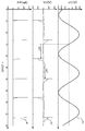
도 21a~도 21d는 트라이액(Tri1)이 온되는 0°, 45°, 90°, 및 135°의 위상각에 대응하는 위상 제어식 조광기(2)의 출력 전압(V2)의 파형과 다이오드 브리지(DB1)의 출력 전압(VDB1)의 파형을 나타낸다. 트라이액(Tri1)이 온되는 위상각이 증가함에 따라 다이오드 브리지(DB1)의 출력 전압(VDB1)의 평균값이 감소되고 조명등 기구[도 20에서는 LED 모듈(3)]의 밝기가 어두워진다.21A-21D show the waveform of the output voltage V 2 of the phase controlled
도 22a~도 22c는 도 20에 나타낸 LED 조명 시스템에 있어서의 LED 모듈(3)의 양단 전압(V3)의 파형예를 나타낸다. 도 22a는 밝은 조광 레벨에서의 LED 모듈(3)의 양단 전압(V3)의 파형을 나타내고 있고, 도 22b는 어두운 조광 레벨에서의 LED 모듈(3)의 양단 전압(V3)의 파형을 나타내고 있고, 도 22c는 중간 조광 레벨(밝은 조광 레벨과 어두운 조광 레벨 사이의 레벨)에서의 LED 모듈(3)의 양단 전압(V3)의 파형을 나타내고 있다.22A to 22C show waveform examples of voltages V 3 at both ends of the
밝은 조광 레벨이 설정된 경우 트라이액(Tri1)이 오프로부터 온으로 스위칭되어 LED 모듈(3)이 점등된 후 LED 모듈(3)의 양단 전압(V3)이 LED 모듈(3)의 순방향 전압(VF)을 하회하면 LED 모듈(3)에 전류가 흐르지 않게 되고 트라이액(Tri1)이 오프된다. 그러므로, LED 모듈(3)의 양단 전압(V3)이 급격히 저하한다(도 22a 참조).When the bright dimming level is set, the triac Tri1 is switched from off to on, and after the
도 23a는 상기 밝은 조광 레벨이 설정된 경우의 도 20에 나타낸 LED 조명 시스템의 각 부의 전압/전류의 시뮬레이션 파형도를 나타낸다. 도 23a는 교류 전원(1)의 출력 전압(V1)의 파형, LED 모듈(3)의 양단 전압(V3), 및 LED 모듈(3)에 흐르는 전류(I3)를 나타내고 있다. 도 23a에 나타낸 시뮬레이션 결과에서는 반고정 저항(Rvar1)의 노브나 슬라이더를 LED 모듈(3)의 광강도가 최대인 위치에 설정되며, 즉 반고정 저항(Rvar1)의 저항값이 0Ω으로 설정되어 있다. 도 23a에 있어서, 트라이액(Tri1)의 온으로의 스위칭 및 LED 모듈(3)의 양단 전압(V3)의 상승은 위상이 53°일 때 발생한다. LED 모듈(3)의 광강도는 LED 모듈(3)의 평균 전류에 비례하고 있기 때문에 LED 모듈(3)의 평균 전류로부터 추정가능하다. LED 모듈(3)의 평균 전류와 반고정 저항(Rvar1)의 저항값의 관계는 도 24에 나타내어져 있다. 위상 제어식 조광기(2)를 설치하지 않은 상태에서의 LED 모듈(3)의 광강도를 100%로 가정하면 도 23a의 시뮬레이션 결과를 얻은 조건에서의 LED 모듈(3)의 광강도는 90.5%이다.FIG. 23A shows a simulation waveform diagram of voltage / current of each part of the LED lighting system shown in FIG. 20 when the bright dimming level is set. FIG. Figure 23a shows a current (I 3) flowing through the both-end voltage (V 3), and the
한편, 어두운 조광 레벨이 설정된 경우 트라이액(Tri1)이 오프로부터 온으로 스위칭되어 LED 모듈(3)이 점등된 후 LED 모듈(3)의 양단 전압(V3)이 LED 모듈(3)의 순방향 전압(VF)을 하회하면 LED 모듈(3)에 전류가 흐르지 않게 된다. 그러나, 위상 제어식 조광기(2) 내부에 위상 시프트용 콘덴서(C2 및 C3)가 있기 때문에 그 콘덴서(C2 및 C3)로부터 트라이액(Tri1)에 전류가 흘러 트라이액(Tri1)이 오프되지 않는다(도 22b 참조).On the other hand, when the dark dimming level is set, the triac Tri1 is switched from off to on, and after the
도 23b는 상기 어두운 조광 레벨이 설정된 경우의 도 20에 나타낸 LED 조명 시스템의 각 부의 전압/전류의 시뮬레이션 파형도를 나타낸다.도 23b는 교류 전원(1)의 출력 전압(V1)의 파형, LED 모듈(3)의 양단 전압(V3), 및 LED 모듈(3)에 흐르는 전류(I3)를 나타내고 있다. 또한, 도 23b는 반고정 저항(Rvar1)의 저항값이 150㏀인 시뮬레이션 결과를 나타내고 있다. 도 23b에 있어서, 트라이액(Tri1)의 온으로의 스위칭 및 LED 모듈(3)의 양단 전압(V3)의 상승은 위상이 141°일 때 발생한다. 도 23b의 시뮬레이션 결과가 얻어지는 조건에서의 LED 모듈(3)의 광강도는 0.71%이다.Fig. 23B shows a simulation waveform diagram of the voltage / current of each part of the LED lighting system shown in Fig. 20 when the dark dimming level is set. Fig. 23B is a waveform of the output voltage V 1 of the
예를 들면, 콘덴서(C2)의 정전용량이 100㎋일 때 저항(R1)의 저항값은 5.6㏀이고, 콘덴서(C2)의 양단 전압의 초기값은 141V이며, 콘덴서(C2)로부터 흐르는 전류는 트라이액(Tri1)의 유지 전류값(여기서는 5㎃)을 하회할 때까지 대략 900㎲ 걸린다. 구체적으로, 콘덴서(C2)에 의한 트라이액(Tri1)의 유지 시간은 대략 900㎲이다. 트라이액(Tri1)이 온된 후 900㎲가 경과된 이후에 LED 모듈(3)에 전류가 흐르지 않게 될 경우는 도 22a에 나타낸 것과 같은 파형이 발생되고, 900㎲이내에 LED 모듈(3)에 전류가 흐르지 않게 될 경우는 도 22b에 나타낸 것과 같은 파형이 발생된다. 도 22c에 나타낸 바와 같이, 도 22a에 나타낸 파형 및 도 22b에 나타낸 파형이 혼재된 파형은 조건이 정확히 두 파형 사이에 있는 경우, 즉 트라이액(Tri1)이 온된 후 900㎲까지 LED 모듈(3)에 전류가 흐르지 않게 될 경우 발생된다. 도 22c에 나타낸 상태가 발생될 때 콘덴서(C2)의 차지량과, 저항(R1) 및 콘덴서(C2)의 시정수의 변동에 의해 LED 모듈(3)에 흐르는 전류가 안정되지 않고, 광이 명멸되고, 플리커링이 저레벨 조광 동안 발생된다.For example, when the capacitance of the capacitor C2 is 100 mA, the resistance value of the resistor R1 is 5.6 mA, the initial value of the voltage across the capacitor C2 is 141 V, and the current flowing from the capacitor C2 is It takes approximately 900 mA until the holding current value of the triac Tri1 (here, 5 mA) is lower. Specifically, the holding time of the triac Tri1 by the capacitor C2 is approximately 900 ms. If no current flows in the
도 23c는 상기 중간 조광 레벨이 설정된 경우의 도 20에 나타낸 LED 조명 시스템의 각 부의 전압/전류의 시뮬레이션 파형도를 나타낸다. 도 23c는 교류 전원(1)의 출력 전압(V1)의 파형, LED 모듈(3)의 양단 전압(V3), 및 LED 모듈(3)에 흐르는 전류(I3)를 나타내고 있다. 또한, 도 23c는 반고정 저항(Rvar1)의 저항값이 135㏀인 시뮬레이션 결과를 나타내고 있다. 도 23c에 있어서, 트라이액(Tri1)이 오프로부터 온으로 스위칭되어 LED 모듈(3)의 양단 전압(V3)이 상승하는 타이밍은 위상이 137°와 141°사이에서 교대로 나타난다. 또한, 도 23c의 시뮬레이션 결과가 얻어지는 조건에서의 LED 모듈(3)의 광강도는 1.58%이다.FIG. 23C shows a simulation waveform diagram of voltage / current of each part of the LED lighting system shown in FIG. 20 when the intermediate dimming level is set. FIG. Figure 23c shows the current (I 3) flowing through the both-end voltage (V 3), and the
상기 저레벨 조광 동안의 플리커링의 문제는 통상 LED 모듈(3)의 광강도가 1~5%정도일 때에 발생하지만, 각종 타입의 조광기가 존재하기 때문에 1~5%의 범위는 단지 근사치이고, 1~5%이외의 강도에서도 저레벨 조광 동안의 플리커링의 문제가 발생한다.The problem of flickering during the low level dimming usually occurs when the light intensity of the
또한, 이하에 기재된 것과 같은 요인은 몇몇 경우에 LED 모듈(3)에서 플리커링을 발생시킨다. 위상 제어식 조광기(2)의 트라이액(Tri1)이 오프로부터 온으로 스위칭될 때 LED 모듈(3)이 오프로부터 온으로 스위칭되고, LED 모듈(3)의 임피던스가 급격히 변화된다. 이에 따라, 위상 제어식 조광기(2)의 출력 전압이 급격히 변화되는 에지 부분에 링잉(ringing)이 발생하고, 이 링잉이 발생하는 기간에 있어서 트라이액(Tri1)에 흐르는 전류가 정 및 부로 수회 진동한 후 트라이액(Tri1)이 오프로 스위칭되고, 그 후 트리거가 발생되어 트라이액(Tri1)에 흐르는 전류가 정 및 부로 수회 진동한 후 트라이액(Tri1)이 오프된다고 하는 현상이 때때로 발생한다. 이 처리가 반복되어 LED 모듈(3)이 명멸된다.In addition, factors such as those described below cause flickering in the
조명등 기구가 백열등일 경우에 부하가 텅스텐 또는 다른 필라멘트이기 때문에 위상 제어식 조광기(2)의 트라이액(Tri1)이 오프로부터 온으로 스위칭될 때에도 임피던스의 최소 변동이 존재하고, 저임피던스의 상태가 유지되며, 위상 제어식 조광기(2)에 흐르는 전류가 급격히 변화되지 않고, 교류 전원(1)의 출력 전압이 0V 부근이 될 때까지 안정한 조광 동작이 가능하다.Since the load is tungsten or other filaments when the luminaire is an incandescent lamp, there is a minimum variation in impedance even when the triac Tri1 of the phase controlled
본 발명의 목적은 위상 제어식 조광기와 함께 이용될 때 발생할 수 있는 LED의 플리커링을 저감할 수 있는 LED 구동 회로, LED 구동 회로를 구비한 LED 조명등 기구, LED 조명 기기, 및 LED 조명 시스템을 제공하는 것이다.SUMMARY OF THE INVENTION An object of the present invention is to provide an LED driving circuit, an LED lighting device having an LED driving circuit, an LED lighting device, and an LED lighting system that can reduce flickering of an LED that may occur when used with a phase controlled dimmer. will be.
상기 목적을 달성하기 위해 본 발명에 의한 LED 구동 회로는 위상 제어식 조광기에 접속가능하고, 교류 전압을 입력해서 LED를 구동하는 LED 구동 회로이며, LED 구동 회로는 상기 위상 제어식 조광기의 출력 전압의 에지를 검출하는 에지 검출기와, LED 구동 전류를 상기 LED에 공급하기 위한 전류 공급 라인으로부터 전류를 추출하는 전류 추출기를 구비하고, 상기 전류 추출기에 의해 상기 전류 공급 라인으로부터 추출되는 전류값은 상기 에지 검출기의 검출 결과에 따라 가변된다.In order to achieve the above object, the LED driving circuit according to the present invention is an LED driving circuit which can be connected to a phase controlled dimmer and inputs an alternating voltage to drive the LED, and the LED driving circuit provides an edge of the output voltage of the phase controlled dimmer. An edge detector for detecting and a current extractor for extracting current from a current supply line for supplying the LED driving current to the LED, wherein a current value extracted from the current supply line by the current extractor is detected by the edge detector; It depends on the result.
또한, 상기 위상 제어식 조광기 내부의 위상 제어 소자의 온/오프 상태가 스위칭되어 상기 LED가 발광된 후 상기 교류 전압이 0V에 도달하기 전에 상기 위상 제어식 조광기 내부의 위상 제어 소자가 오프되지 않도록 상기 전류 추출기가 상기 전류 공급 라인으로부터 제 1 추출 전류를 추출하고, 상기 에지 검출기가 상기 위상 제어식 조광기의 출력 전압의 에지를 검출하면 미리 설정된 시간 동안 상기 전류 추출기가 상기 전류 공급 라인으로부터 상기 제 1 추출 전류와 다른 값을 갖는 제 2 추출 전류를 추출하는 구성이 채택될 수 있다.In addition, the current extractor so that the on / off state of the phase control element inside the phase controlled dimmer is switched so that the phase control element inside the phase controlled dimmer is not turned off before the AC voltage reaches 0V after the LED is emitted. Extracts a first extraction current from the current supply line, and when the edge detector detects an edge of the output voltage of the phase controlled dimmer, the current extractor is different from the first supply current from the current supply line for a preset time. A configuration for extracting a second extraction current having a value can be adopted.
또한, 상기 LED 구동 회로는 상기 전류 추출기에 의해 사용되는 기준 전압의 값을 스위칭함으로써 상기 제 1 추출 전류와 상기 제 2 추출 전류를 스위칭할 수 있다.In addition, the LED driving circuit may switch the first extraction current and the second extraction current by switching the value of the reference voltage used by the current extractor.
또한, 상기 LED 구동 회로는 상기 에지 검출기가 상기 위상 제어식 조광기의 출력 전압의 에지를 일정 기간 검출하지 않을 경우 상기 전류 추출기를 동작시키지 않도록 구성될 수 있다.In addition, the LED driving circuit may be configured to not operate the current extractor when the edge detector does not detect an edge of the output voltage of the phase controlled dimmer for a predetermined period of time.
또한, 상기 LED 구동 회로는 상기 LED 구동 전류를 검출하는 전류 검출기를 포함할 수 있고, 상기 LED 구동 회로는 상기 전류 검출기의 검출 결과에 따라 상기 제 1 추출 전류에 의해 상기 전류 추출기의 전류 추출 동작의 온/오프 상태를 제어할 수 있다.The LED driving circuit may further include a current detector for detecting the LED driving current, wherein the LED driving circuit is configured to extract the current extraction operation of the current extractor by the first extraction current according to a detection result of the current detector. The on / off state can be controlled.
또한, 상기 LED 구동 회로는 상기 LED 구동 전류를 검출하는 전류 검출기를 포함할 수 있고, 상기 LED 구동 회로는 상기 전류 검출기의 검출 결과에 따라 상기 제 1 추출 전류값을 가변할 수 있다.In addition, the LED driving circuit may include a current detector for detecting the LED driving current, the LED driving circuit may vary the first extraction current value according to the detection result of the current detector.
또한, 상기 LED 구동 회로는 상기 교류 전압 또는 상기 교류 전압을 정류함으로써 얻어진 전압을 검출하는 전압 검출기를 포함할 수 있고, 상기 LED 구동 회로는 상기 전압 검출기의 검출 결과에 따라 상기 제 1 추출 전류값과 상기 제 2 추출 전류값을 가변할 수 있다.In addition, the LED driving circuit may include a voltage detector for detecting the AC voltage or a voltage obtained by rectifying the AC voltage, the LED driving circuit and the first extraction current value according to the detection result of the voltage detector; The second extraction current value may be varied.
또한, 상기 에지 검출기는 상승 에지와 하강 에지를 식별할 수 있도록 구성될 수 있다.In addition, the edge detector may be configured to identify rising edges and falling edges.
또한, 상기 전류 추출기보다도 상기 전류 공급 라인의 입력측에 코일이 더 제공될 수 있고, 상기 제 2 추출 전류는 펄스 형상 파형을 가질 수 있다.In addition, a coil may be further provided at an input side of the current supply line than the current extractor, and the second extraction current may have a pulse shape waveform.
또한, 상기 LED 구동 회로가 상기 교류 전압 또는 상기 교류 전압을 정류함으로써 얻어진 전압을 검출하는 전압 검출기와, 상기 전압 검출기의 검출 결과 및 상기 에지 검출기의 검출 결과에 따라 상기 교류 전압이 제로 부근에 도달하는 포인트와 상기 교류 전압이 급격히 변화되는 포인트의 시간 차이를 검출하는 시간 차이 검출기를 구비하고, 상기 LED 구동 회로가 상기 시간 차이 검출기의 검출 결과에 따라 상기 LED를 단락할 지의 여부를 스위칭하는 구성이 채택될 수 있다.Further, a voltage detector for detecting the voltage obtained by rectifying the AC voltage or the AC voltage by the LED driving circuit, and the AC voltage reaches near zero according to a detection result of the voltage detector and a detection result of the edge detector. A time difference detector for detecting a time difference between a point and a point at which the AC voltage changes rapidly, and a configuration for switching whether or not the LED driving circuit shorts the LED according to a detection result of the time difference detector is adopted. Can be.
또한, 상기 LED 구동 회로는 상기 에지 검출기의 출력을 지연시키는 지연 유닛을 포함하고, 상기 LED 구동 회로는 상기 지연 유닛의 출력에 따라 상기 LED를 단락할 지의 여부를 스위칭할 수 있다.The LED driving circuit may also include a delay unit for delaying the output of the edge detector, and the LED driving circuit may switch whether or not to short the LED according to the output of the delay unit.
또한, 상기 전류 추출기는 상기 제 2 추출 전류의 하강 시간을 변경할 수 있는 하강 시간 변경 유닛을 가질 수 있다.In addition, the current extractor may have a fall time changing unit capable of changing the fall time of the second extraction current.
또한, 상기 하강 시간 변경 유닛은 전류 출력의 연산 증폭기에 접속되는 오차 증폭기와, 상기 오차 증폭기의 출력에 접속되는 용량을 가질 수 있다.In addition, the fall time changing unit may have an error amplifier connected to the operational amplifier of the current output, and a capacity connected to the output of the error amplifier.
또한, 상기 하강 시간 변경 유닛은 피크 홀드 회로와 방전 회로를 가질 수 있다.In addition, the fall time changing unit may have a peak hold circuit and a discharge circuit.
또한, 상기 LED 구동 회로는 상기 LED가 온될 때에 상기 제 1 추출 전류에 의한 전류 추출 동작을 오프하지 않도록 구성될 수 있다.In addition, the LED driving circuit may be configured not to turn off the current extraction operation by the first extraction current when the LED is turned on.
상기 목적을 달성하기 위해 본 발명에 의한 LED 조명등 기구는 상기 본 발명의 실시형태 중 어느 하나에 의한 LED 구동 회로와, 상기 LED 구동 회로의 출력측에 접속된 LED를 포함한다.In order to achieve the above object, the LED lighting fixture according to the present invention includes an LED driving circuit according to any one of the embodiments of the present invention, and an LED connected to an output side of the LED driving circuit.
상기 목적을 달성하기 위해 본 발명에 의한 LED 조명 기기는 상기 본 발명의 실시형태 중 어느 하나에 의한 LED 구동 회로 또는 상기 본 발명의 실시형태 중 어느 하나에 의한 LED 조명등 기구를 포함한다.In order to achieve the above object, the LED lighting apparatus according to the present invention includes the LED driving circuit according to any one of the embodiments of the present invention or the LED lighting apparatus according to any one of the embodiments of the present invention.
상기 목적을 달성하기 위해서 본 발명에 의한 LED 조명 시스템은 상기 본 발명의 실시형태 중 어느 하나에 의한 LED 조명등 기구 또는 상기 본 발명에 의한 LED 조명 기기와, 상기 LED 조명등 기구 또는 LED 조명 기기의 입력측에 접속된 위상 제어식 조광기를 포함한다.In order to achieve the above object, the LED lighting system according to the present invention includes an LED lighting device according to any one of the embodiments of the present invention or an LED lighting device according to the present invention, and an input side of the LED lighting device or the LED lighting device. And a connected phase controlled dimmer.
본 발명에 의하면, 위상 제어식 조광기의 출력 전압의 에지의 유무에 의해 전류 추출량이 변경될 수 있으므로 복수의 요인에 의한 LED의 플리커링이 저감될 수 있다.According to the present invention, since the amount of current extraction can be changed by the presence or absence of the edge of the output voltage of the phase controlled dimmer, the flickering of the LED due to a plurality of factors can be reduced.
도 1은 본 발명의 제 1 실시형태에 의한 LED 조명 시스템의 구성을 나타내는 도이다.
도 2는 본 발명의 제 2 실시형태에 의한 LED 조명 시스템의 구성을 나타내는 도이다.
도 3은 본 발명의 제 3 실시형태에 의한 LED 조명 시스템의 구성을 나타내는 도이다.
도 4는 본 발명의 제 4 실시형태에 의한 LED 조명 시스템의 구성을 나타내는 도이다.
도 5는 본 발명의 제 5 실시형태에 의한 LED 조명 시스템의 구성을 나타내는 도이다.
도 6은 본 발명의 제 6 실시형태에 의한 LED 조명 시스템의 구성을 나타내는 도이다.
도 7은 위상 제어식 조광기의 출력 전압의 파형과 다이오드 브리지의 출력 전압의 파형을 나타내는 도이다.
도 8은 본 발명의 제 7 실시형태에 의한 LED 조명 시스템의 구성을 나타내는 도이다.
도 9는 본 발명의 제 8 실시형태에 의한 LED 조명 시스템의 구성을 나타내는 도이다.
도 10은 다이오드 브리지의 출력 전압의 파형을 나타내는 도이다.
도 11은 본 발명의 제 9 실시형태에 의한 LED 조명 시스템의 구성을 나타내는 도이다.
도 12는 본 발명의 제 10 실시형태에 의한 LED 조명 시스템의 구성을 나타내는 도이다.
도 13은 다이오드 브리지의 출력 전압, 추출 전류, 및 LED 모듈에 흐르는 전류의 파형의 일예를 나타내는 도이다.
도 14는 본 발명의 제 11 실시형태에 의한 LED 조명 시스템의 요점부 구성을 나타내는 도이다.
도 15는 다이오드 브리지의 출력 전압, 추출 전류, 및 LED 모듈에 흐르는 전류의 파형의 일예를 나타내는 도이다.
도 16은 본 발명의 제 12 실시형태에 의한 LED 조명 시스템의 구성을 나타내는 도이다.
도 17은 다이오드 브리지의 출력 전압, 추출 전류, 및 LED 모듈에 흐르는 전류의 파형의 일예를 나타내는 도이다.
도 18은 본 발명에 의한 LED 조명등 기구, 본 발명에 의한 LED 조명 기기, 및 본 발명에 의한 LED 조명 시스템의 개략 구조 예를 나타내는 도이다.
도 19는 본 발명에 의한 LED 조명등 기구의 다른 개략 구조 예를 나타내는 도이다.
도 20은 LED 조명 시스템의 종래 예를 나타내는 도이다.
도 21a는 위상 제어식 조광기의 출력 전압의 파형과 다이오드 브리지의 출력 전압의 파형을 나타내는 도이다.
도 21b는 위상 제어식 조광기의 출력 전압의 파형과 다이오드 브리지의 출력 전압의 파형을 나타내는 도이다.
도 21c는 위상 제어식 조광기의 출력 전압의 파형과 다이오드 브리지의 출력 전압의 파형을 나타내는 도이다.
도 21d는 위상 제어식 조광기의 출력 전압의 파형과 다이오드 브리지의 출력 전압의 파형을 나타내는 도이다.
도 22a는 밝은 조광 레벨이 설정된 경우의 도 20에 나타낸 LED 조명 시스템에 있어서의 LED 모듈의 양단 전압의 파형 예를 나타내는 도이다.
도 22b는 어두운 조광 레벨이 설정된 경우의 도 20에 나타낸 LED 조명 시스템에 있어서의 LED 모듈의 양단 전압의 파형 예를 나타내는 도이다.
도 22c는 중간 조광 레벨이 설정된 경우의 도 20에 나타낸 LED 조명 시스템에 있어서의 LED 모듈의 양단 전압의 파형 예를 나타내는 도이다.
도 23a는 밝은 조광 레벨이 설정된 경우의 도 20에 나타낸 LED 조명 시스템의 각 부의 전압/전류의 시뮬레이션 파형도이다.
도 23b는 어두운 조광 레벨이 설정된 경우의 도 20에 나타낸 LED 조명 시스템의 각 부의 전압/전류의 시뮬레이션 파형도이다.
도 23c는 중간 조광 레벨이 설정된 경우의 도 20에 나타낸 LED 조명 시스템의 각 부의 전압/전류의 시뮬레이션 파형도이다.
도 24는 LED 모듈의 평균 전류와 반고정 저항의 저항값의 관계를 나타내는 도이다.1 is a diagram illustrating a configuration of an LED lighting system according to a first embodiment of the present invention.
It is a figure which shows the structure of the LED lighting system which concerns on 2nd Embodiment of this invention.
It is a figure which shows the structure of the LED lighting system which concerns on 3rd Embodiment of this invention.
It is a figure which shows the structure of the LED lighting system which concerns on 4th Embodiment of this invention.
It is a figure which shows the structure of the LED lighting system which concerns on 5th Embodiment of this invention.
It is a figure which shows the structure of the LED lighting system which concerns on 6th Embodiment of this invention.
7 is a diagram showing the waveform of the output voltage of the phase controlled dimmer and the waveform of the output voltage of the diode bridge.
It is a figure which shows the structure of the LED lighting system which concerns on 7th Embodiment of this invention.
It is a figure which shows the structure of the LED lighting system which concerns on 8th Embodiment of this invention.
10 is a diagram showing waveforms of an output voltage of a diode bridge.
It is a figure which shows the structure of the LED lighting system which concerns on 9th Embodiment of this invention.
It is a figure which shows the structure of the LED lighting system which concerns on 10th Embodiment of this invention.
13 is a diagram showing an example of waveforms of an output voltage of a diode bridge, an extraction current, and a current flowing through the LED module.
It is a figure which shows the main part structure of the LED lighting system which concerns on 11th Embodiment of this invention.
15 is a diagram illustrating an example of waveforms of an output voltage of a diode bridge, an extraction current, and a current flowing through the LED module.
It is a figure which shows the structure of the LED lighting system which concerns on 12th Embodiment of this invention.
17 is a diagram showing an example of waveforms of an output voltage of a diode bridge, an extraction current, and a current flowing through the LED module.
It is a figure which shows the schematic structural example of the LED lighting fixture by this invention, the LED lighting apparatus by this invention, and the LED lighting system by this invention.
It is a figure which shows the other schematic structural example of the LED lamp fixture by this invention.
20 is a diagram illustrating a conventional example of an LED lighting system.
Fig. 21A is a diagram showing the waveform of the output voltage of the phase controlled dimmer and the waveform of the output voltage of the diode bridge.
Fig. 21B is a diagram showing the waveform of the output voltage of the phase controlled dimmer and the waveform of the output voltage of the diode bridge.
Fig. 21C is a diagram showing the waveform of the output voltage of the phase controlled dimmer and the waveform of the output voltage of the diode bridge.
Fig. 21D is a diagram showing the waveform of the output voltage of the phase controlled dimmer and the waveform of the output voltage of the diode bridge.
It is a figure which shows the example of the waveform of the voltage of the both ends of the LED module in the LED lighting system shown in FIG. 20 when a bright dimming level is set.
22B is a diagram showing an example of waveforms of voltages at both ends of the LED module in the LED lighting system shown in FIG. 20 when a dark dimming level is set.
22C is a diagram showing an example of waveforms of voltages at both ends of the LED module in the LED lighting system shown in FIG. 20 when the intermediate dimming level is set.
FIG. 23A is a simulation waveform diagram of voltage / current of each part of the LED lighting system shown in FIG. 20 when a bright dimming level is set. FIG.
FIG. 23B is a simulation waveform diagram of voltage / current of each part of the LED lighting system shown in FIG. 20 when a dark dimming level is set. FIG.
FIG. 23C is a simulation waveform diagram of voltage / current of each part of the LED lighting system shown in FIG. 20 when an intermediate dimming level is set. FIG.
24 is a diagram illustrating a relationship between the average current of the LED module and the resistance value of the semi-fixed resistor.
본 발명의 실시형태는 도면을 참조해서 이하에 설명한다.Embodiments of the present invention will be described below with reference to the drawings.
<제 1 실시형태>≪ First Embodiment >
도 1은 본 발명의 제 1 실시형태에 의한 LED 조명 시스템의 구성을 나타낸다. 도 1에 있어서 도 20과 동일한 부분에는 동일 참조 부호가 사용되어 그 상세한 설명이 제공되지 않을 것이다. 도 1에 나타낸 본 발명의 제 1 실시형태에 의한 LED 조명 시스템은 위상 제어식 조광기(2)와, LED 모듈(3)과, LED 구동 회로(4A)를 구비하고 있다. LED 구동 회로(4A)는 본 발명에 의한 LED 구동 회로의 일예이며, 다이오드 브리지(DB1)와, 에지 검출 회로(5)와, 제 1 기준 전압 생성 회로(6)와, 제 2 기준 전압 생성 회로(7)와, 스위치(8)와, 전류 추출 회로(9)와, 레귤레이터 회로(10)를 갖고 있다.1 shows a configuration of an LED lighting system according to a first embodiment of the present invention. In FIG. 1, the same reference numerals are used for the same parts as in FIG. 20, and a detailed description thereof will not be provided. The LED lighting system which concerns on 1st Embodiment of this invention shown in FIG. 1 is equipped with the
도 1에 나타낸 본 발명의 제 1 실시형태에 의한 LED 조명 시스템에서는 교류 전원(1)과 위상 제어식 조광기(2)가 다이오드 브리지(DB1)의 입력측에 직렬 접속되고, 1개이상의 LED로 이루어지는 LED 모듈(3)과 레귤레이터 회로(10)가 다이오드 브리지(DB1)의 출력측에 직렬 접속되어 있다. 전류 추출 회로(9)가 LED 모듈(3) 및 레귤레이터 회로(10)로 이루어지는 직렬 회로에 병렬 접속되어 있다.In the LED lighting system according to the first embodiment of the present invention shown in FIG. 1, an
위상 제어식 조광기(2)의 출력 전압(V2)의 파형예 및 다이오드 브리지(DB1)의 출력 전압(VDB1)의 파형예는 도 21a~도 21d에 도시되어 있다.Examples of waveforms of the output voltage V 2 of the phase controlled
에지 검출 회로(5)는 구동시에 LED 구동 전류를 LED 모듈(3)에 공급하기 위한 전원 공급 라인(LN1)의 전압(VLN1)의 급격한 변화(에지)를 검출한다. 제 1 기준 전압 생성 회로(6)는 제 1 기준 전압을 생성하고, 제 2 기준 전압 생성 회로(7)는 제 1 기준 전압과 다른 값을 갖는 제 2 기준 전압을 생성한다.The
에지 검출 회로(5)가 전압(VLN1)의 에지를 검출하면 스위치(8)는 제 2 기준 전압 생성 회로(7)로부터 출력되는 제 2 기준 전압을 선택하고, 제 2 기준 전압을 전류 추출 회로(9)에 공급한다. 또한, 에지 검출 회로(5)가 전압(VLN1)의 에지를 검출한 후 소정 시간이 경과하면 스위치(8)는 제 1 기준 전압 생성 회로(6)로부터 출력되는 제 1 기준 전압을 선택하고, 제 1 기준 전압을 전류 추출 회로(9)에 공급한다. 상기 소정 시간은 통상 위상 제어식 조광기(2)의 출력 전압의 링잉을 적절히 수용하는 시간에 설정된다.When the
전류 추출 회로(9)는 전원 공급 라인(LN1)으로부터 전류를 추출하는 회로이며, 전원 공급 라인(LN1)으로부터 추출된 전류값을 기준 전압의 값에 따라 가변한다. 전류 추출 회로(9)의 추출 전류값은 스위치(8)로부터 전류 추출 회로(9)로 제 1 기준 전압이 공급되어 있을 때보다도 스위치(8)로부터 전류 추출 회로(9)로 제 2 기준 전압이 공급되어 있을 때 커진다.The current extracting
레귤레이터 회로(10)는 LED 모듈(3)에 흐르는 LED 구동 전류를 일정하게 하는 회로이다.The
위상 제어식 조광기(2)의 출력 전압의 링잉 기간[위상 제어식 조광기(2) 내의 잡음 방지 필터를 구성하는 콘덴서(C1)와 인덕터(L1)에 의한 공진 파장2π√(LC)의 수 주기분의 기간, 여기서 L은 인덕터(L1)의 인덕턴스값, C는 콘덴서(C1)의 정전용량값임]에 있어서, 전류 추출 회로(9)의 추출 전류(제 2 기준 전압에 따른 추출 전류)에 의해 트라이액(Tri1)의 유지 전류가 확보되어 트라이액(Tri1)이 오프되지 않는다. 그러므로, 위상 제어식 조광기(2)의 트라이액(Tri1)이 오프로부터 온으로 스위칭될 때에 LED 모듈(3)의 플리커링이 저감될 수 있다.Ringing period of the output voltage of the phase controlled dimmer 2 (period of several cycles of the resonant wavelength 2π√LC by the capacitor C1 and the inductor L1 constituting the anti-noise filter in the phase controlled dimmer 2) Where L is the inductance value of the inductor L1, C is the capacitance value of the capacitor C1, and the triac (the extraction current according to the second reference voltage) of the
위상 제어식 조광기(2) 내부의 트라이액(Tri1)이 온되어 LED 모듈(3)이 발광된 후 교류 전원(1)의 출력 전압이 0V에 도달하기 전에 전류 추출 회로(9)의 추출 전류(제 1 기준 전압에 따른 추출 전류)에 의해 트라이액(Tri1)의 유지 전류가 확보되어 트라이액(Tri1)이 오프되지 않으므로 저레벨 조광 동안의 LED 모듈(3)의 플리커링을 저감할 수 있다. 트라이액(Tri1)의 유지 전류가 충분히 확보될 수 있는 범위에서 제 1 기준 전압에 따른 추출 전류를 설정함으로써 전류 추출 회로(9)에서의 전력 소비가 낮게 유지될 수 있다.After the triac Tri1 inside the phase controlled
전류 추출 회로(9)의 각 추출 전류(제 1 기준 전압에 따른 추출 전류, 제 2 기준 전압에 따른 추출 전류)의 값은 전류 추출 회로(9)가 트라이액(Tri1)에 흐르는 전류뿐만 아니라 직접 트라이액(Tri1)에 흐르지 않는 전류도 추출한다는 사실을 고려해서 설정되어야 한다.The value of each extraction current (extraction current according to the first reference voltage, extraction current according to the second reference voltage) of the
또한, 제 1 기준 전압 생성 회로(6)와 제 2 기준 전압 생성 회로(7)는 구성 부품의 일부 또는 전부를 공용할 수 있다.In addition, the first
<제 2 실시형태>≪ Second Embodiment >
도 2는 본 발명의 제 2 실시형태에 의한 LED 조명 시스템의 구성을 나타낸다. 도 2에 있어서 도 1과 동일한 부분에는 동일 참조 부호가 사용되어 그 상세한 설명이 제공되지 않을 것이다. 도 2에 나타낸 본 발명의 제 2 실시형태에 의한 LED 조명 시스템은 위상 제어식 조광기(2)와, LED 모듈(3)과, LED 구동 회로(4B)를 구비하고 있다. LED 구동 회로(4B)는 본 발명에 의한 LED 구동 회로의 일예이며, 상술한 LED 구동 회로(4A)에 스위치(11)를 추가한 구성을 갖고 있다.2 shows a configuration of an LED lighting system according to a second embodiment of the present invention. In FIG. 2, the same reference numerals are used for the same parts as in FIG. 1, and a detailed description thereof will not be provided. The LED lighting system by 2nd Embodiment of this invention shown in FIG. 2 is equipped with the
스위치(11)는 전원 공급 라인(LN1)과 전류 추출 회로(9) 사이에 제공된다. 에지 검출 회로(5)가 전압(VLN1)의 에지를 일정 기간[예를 들면, 교류 전원(1)의 출력 전압의 반주기] 검출하지 않을 경우, 즉 위상 제어식 조광기(2)가 조광 동작을 하지 않고 있을 경우나 도 2의 구성과는 다르게 LED 구동 회로(4B)가 교류 전원(1)에 직접 접속되어 있을 경우, 스위치(11)는 전류 추출 회로(9)가 전류를 추출하지 못하도록 오프된다.The switch 11 is provided between the power supply line LN1 and the
위상 제어식 조광기(2)가 조광 동작을 하지 않고 있을 경우나 도 2의 구성과는 다르게 LED 구동 회로(4B)가 교류 전원(1)에 직접 접속되어 있을 경우, 통상 전류 추출 회로(9)의 전류 추출 동작은 필요하지 않으므로 스위치(11)의 오프에 의해 전류 추출 회로(9)가 전류를 추출하지 못하도록 함으로써 전류 추출 회로(9)에서의 불필요한 전력 소비가 제거되어 효율이 향상될 수 있다. 또한, 현재 조광기 대응 또는 비대응인 상품으로 분류되는 LED 조명등 기구를 공통화할 수 있고, 조광기 대응 또는 비대응에 의한 상품 구분을 폐지할 수 있다.When the phase controlled
<제 3 실시형태>≪ Third Embodiment >
도 3은 본 발명의 제 3 실시형태에 의한 LED 조명 시스템의 구성을 나타낸다. 도 3에 있어서 도 2와 동일한 부분에는 동일 참조 부호가 사용되어 그 상세한 설명이 제공되지 않을 것이다. 도 3에 나타낸 본 발명의 제 3 실시형태에 의한 LED 조명 시스템은 위상 제어식 조광기(2)와, LED 모듈(3)과, LED 구동 회로(4C)를 구비하고 있다. LED 구동 회로(4C)는 본 발명에 의한 LED 구동 회로의 일예이며, 상술한 LED 구동 회로(4B)에 전류 검출 회로(12)를 추가한 구성을 갖고 있다.3 shows a configuration of an LED lighting system according to a third embodiment of the present invention. In FIG. 3, the same reference numerals are used for the same parts as those in FIG. 2, and a detailed description thereof will not be provided. The LED illumination system which concerns on 3rd Embodiment of this invention shown in FIG. 3 is equipped with the
전류 검출 회로(12)는 LED 모듈(3)에 흐르는 LED 구동 전류를 검출한다. 스위치(11)는 에지 검출 회로(5)의 검출 결과라기보다는 전류 검출 회로(12)의 검출 결과에 따라 동작한다. 위상 제어식 조광기(2)의 관점에서 LED 모듈(3)에 LED 구동 전류가 흐르고 있을 경우는 전류 추출 회로(9)에 의해 추출되는 전류와 등가이다. 그러므로, 본 실시형태에서는 전류 검출 회로(12)에 의해 검출되는 LED 구동 전류가 미리 설정된 역치를 하회하는 기간 동안 스위치(11)는 전류 추출 회로(9)가 전류를 추출시키도록 온된다. 이에 따라, 전류 추출 회로(9)의 불필요한 전류 추출이 저감될 수 있으므로 효율이 향상한다. 또한, 현재 조광기 대응 또는 비대응인 상품으로 분류되는 LED 조명등 기구를 공통화할 수 있고, 조광기 대응 또는 비대응에 의한 상품 구분을 폐지할 수 있다.The
<제 4 실시형태>Fourth Embodiment
도 4는 본 발명의 제 4 실시형태에 의한 LED 조명 시스템의 구성을 나타낸다. 도 4에 있어서 도 3과 동일한 부분에는 동일 참조 부호가 사용되어 그 상세한 설명이 제공되지 않을 것이다. 도 4에 나타낸 본 발명의 제 4 실시형태에 의한 LED 조명 시스템은 위상 제어식 조광기(2)와, LED 모듈(3)과, LED 구동 회로(4D)를 구비하고 있다. LED 구동 회로(4D)는 본 발명에 의한 LED 구동 회로의 일예이며, 상술한 LED 구동 회로(4C)의 구성으로부터 스위치(11)를 제거하고, 제 1 기준 전압 생성 회로(6)를 제 1 기준 전압의 값을 변경할 수 있는 제 1 기준 전압 생성 회로(6')로 치환하도록 구성된다.4 shows a configuration of an LED lighting system according to a fourth embodiment of the present invention. In FIG. 4, the same reference numerals are used for the same parts as in FIG. 3, and thus a detailed description thereof will not be provided. The LED lighting system which concerns on 4th Embodiment of this invention shown in FIG. 4 is equipped with the
제 1 기준 전압 생성 회로(6')는 전류 검출 회로(12)의 검출 결과에 따라 제 1 기준 전압의 값을 변경하고, LED 모듈(3)에 흐르는 LED 구동 전류와 전류 추출 회로(9)의 추출 전류(제 1 기준 전압에 따른 추출 전류)의 합이 일정 값이 되도록 되어 있다. 이에 따라, 효율이 더욱 향상된다.The first reference voltage generation circuit 6 'changes the value of the first reference voltage according to the detection result of the
<제 5 실시형태>≪
도 5는 본 발명의 제 5 실시형태에 의한 LED 조명 시스템의 구성을 나타낸다. 도 5에 있어서 도 1과 동일한 부분에는 동일 참조 부호가 사용되어 그 상세한 설명이 제공되지 않을 것이다. 도 5에 나타낸 본 발명의 제 5 실시형태에 의한 LED 조명 시스템은 위상 제어식 조광기(2)와, LED 모듈(3)과, LED 구동 회로(4E)를 구비하고 있다. LED 구동 회로(4E)는 본 발명에 의한 LED 구동 회로의 일예이며, 상술한 LED 구동 회로(4A)의 구성에 전압 검출 회로(13)를 추가하고, 제 1 기준 전압 생성 회로(6)를 제 1 기준 전압의 값을 변경할 수 있는 제 1 기준 전압 생성 회로(6')로 치환하고, 제 2 기준 전압 생성 회로(7)를 제 2 기준 전압의 값을 변경할 수 있는 제 2 기준 전압 생성 회로(7')로 치환하도록 구성된다.5 shows a configuration of an LED lighting system according to a fifth embodiment of the present invention. In FIG. 5, the same reference numerals are used for the same parts as in FIG. 1, and a detailed description thereof will not be provided. The LED lighting system which concerns on 5th Embodiment of this invention shown in FIG. 5 is equipped with the
전압 검출 회로(13)는 전원 공급 라인(LN1)의 전압(VLN1)을 검출한다. 제 1 기준 전압 생성 회로(6')는 전압 검출 회로(13)의 검출 결과에 따라 제 1 기준 전압의 값을 변경하고, 제 2 기준 전압 생성 회로(7')는 전압 검출 회로(13)의 검출 결과에 따라 제 2 기준 전압의 값을 변경한다. 상용 교류 전원은 세계 각국에서 100V~240V의 전압 범위에 혼재되어 있고, 교류 전원(1)의 전압값에 의해 최적의 추출 전류값이 변화되기 때문에 본 실시형태와 같이 전원 공급 라인(LN1)의 전압(VLN1)에 따라 전류 추출 회로(9)의 추출 전류값을 변경하는 구성을 채택함으로써 다양한 상용 전원에 대하여 1종류의 LED 조명등 기구가 대응가능하다.The
<제 6 실시형태>≪ Sixth Embodiment &
도 6은 본 발명의 제 6 실시형태에 의한 LED 조명 시스템의 구성을 나타낸다. 도 6에 있어서 도 1과 동일한 부분에는 동일 참조 부호가 사용되어 그 상세한 설명이 제공되지 않을 것이다. 도 6에 나타낸 본 발명의 제 6 실시형태에 의한 LED 조명 시스템은 위상 제어식 조광기(2)와, LED 모듈(3)과, LED 구동 회로(4F)를 구비하고 있다. LED 구동 회로(4F)는 본 발명에 의한 LED 구동 회로의 일예이며, 상술한 LED 구동 회로(4A)의 구성에서 에지 검출 회로(5)를 상승/하강 에지 검출 회로(14)로 치환하고, 제 1 기준 전압 생성 회로(6)를 제 1 기준 전압의 값을 변경할 수 있는 제 1 기준 전압 생성 회로(6')로 치환하고, 제 2 기준 전압 생성 회로(7)를 제 2 기준 전압의 값을 변경할 수 있는 제 2 기준 전압 생성 회로(7')로 치환하도록 구성된다.6 shows a configuration of an LED lighting system according to a sixth embodiment of the present invention. In FIG. 6, the same reference numerals are used for the same parts as in FIG. 1, and a detailed description thereof will not be provided. The LED illumination system which concerns on 6th Embodiment of this invention shown in FIG. 6 is equipped with the
위상 제어식 조광기는 위상 제어 소자가 오프로부터 온으로 스위칭됨으로써 위상 제어가 수행되는 타입(도 21a~도 21d참조)[예를 들면, 위상 제어식 조광기(2)]뿐만 아니라 위상 제어 소자가 온으로부터 오프로 스위칭됨으로써 위상 제어가 수행되는 타입(도 7 참조)을 포함한다.The phase controlled dimmer is a type in which phase control is performed by switching the phase control element from off to on (see FIGS. 21A to 21D) (for example, the phase controlled dimmer 2), as well as the phase control element from on to off. And the type in which phase control is performed by switching (see FIG. 7).
상승/하강 에지 검출 회로(14)는 전원 공급 라인(LN1)의 전압(VLN1)의 에지를 검출하고, 더욱이 검출된 에지가 상승 에지 또는 하강 에지인지를 판별한다. 제 1 기준 전압 생성 회로(6')는 상승/하강 에지 검출 회로(14)에 의해 검출된 에지가 상승 에지 또는 하강 에지인지에 따라 제 1 기준 전압의 값을 변경하고, 제 2 기준 전압 생성 회로(7')는 상승/하강 에지 검출 회로(14)에 의해 검출된 에지가 상승 에지 또는 하강 에지인지에 따라 제 2 기준 전압의 값을 변경한다. 이렇게, 위상 제어식 조광기의 타입에 따라 전류 추출 회로(9)의 추출 전류값을 변경하는 구성을 채택함으로써 위상 제어식 조광기의 타입이 상이해도 최적의 추출 전류값을 설정할 수 있다. 이에 따라, 조광 성능과 효율이 향상될 수 있다.The rising / falling
<제 7 실시형태>≪ Seventh Embodiment &
도 8은 본 발명의 제 7 실시형태에 의한 LED 조명 시스템의 구성을 나타낸다. 도 8에 있어서 도 1과 동일한 부분에는 동일 참조 부호가 사용되어 그 상세한 설명이 제공되지 않을 것이다. 도 8에 나타낸 본 발명의 제 7 실시형태에 의한 LED 조명 시스템은 위상 제어식 조광기(2)와, LED 모듈(3)과, LED 구동 회로(4G)를 구비하고 있다. LED 구동 회로(4G)은 본 발명에 의한 LED 구동 회로의 일예이며, 상술한 LED 구동 회로(4A)에 코일(15)을 추가한 구성을 갖는다.8 shows a configuration of an LED lighting system according to a seventh embodiment of the present invention. In FIG. 8, the same reference numerals are used for the same parts as in FIG. 1, and a detailed description thereof will not be provided. The LED illumination system which concerns on 7th Embodiment of this invention shown in FIG. 8 is equipped with the
코일(15)은 전원 공급 라인(LN1) 상의 에지 검출 회로(5)와 전류 추출 회로(9) 사이에 배치된다. 전류 추출 회로(9)의 제 2 기준 전압에 따른 추출 전류를 펄스 형상으로 함으로써 코일(15)에 에너지를 저장할 수 있으므로 효율을 향상시킬 수 있다.The
<제 8 실시형태>Eighth Embodiment
도 9는 본 발명의 제 8 실시형태에 의한 LED 조명 시스템의 구성을 나타낸다. 도 9에 있어서 도 1과 동일한 부분에는 동일 참조 부호가 사용되어 그 상세한 설명이 제공되지 않을 것이다. 도 9에 나타낸 본 발명의 제 8 실시형태에 의한 LED 조명 시스템은 위상 제어식 조광기(2)와, LED 모듈(3)과, LED 구동 회로(4H)를 구비하고 있다. LED 구동 회로(4H)는 본 발명에 의한 LED 구동 회로의 일예이며, 상술한 LED 구동 회로(4A)에 전압 검출 회로(13), 시간 차이 검출 회로(16), 및 스위치(17)를 추가한 구성을 갖는다.9 shows a configuration of an LED lighting system according to an eighth embodiment of the present invention. In FIG. 9, the same reference numerals are used for the same parts as in FIG. 1, and a detailed description thereof will not be provided. The LED lighting system by 8th Embodiment of this invention shown in FIG. 9 is equipped with the
전압 검출 회로(13)는 전원 공급 라인(LN1)의 전압(VLN1)을 검출한다. 시간 차이 검출 회로(16)는 전압 검출 회로(13)의 검출 결과와 에지 검출 회로(5)의 검출 결과에 의거하여 전압(VLN1)이 제로 부근에 도달하는 포인트(P1)와 전압(VLN1)이 급격히 변화되는 포인트(P2)의 시간 차이(ΔT)(도 10 참조)를 검출한다.The
스위치(17)는 LED 모듈(3)에 병렬 접속되어 있고, 전압 검출 회로(13)에 의해 검출된 시간 차이(ΔT)가 설정된 범위 이상이면 온된다. 본 실시형태에서는 위상 제어식 조광기(2)의 트라이액(Tri1)이 오프로부터 온으로 스위칭되는 위상이 클 때는 LED 모듈(3)을 완전히 소등할 수 있다. 따라서, 본 실시형태는 위상 제어식 조광기(2)의 출력을 좁혔을 경우에 LED가 소등하지 않을 경우의 유효한 대책이다.The switch 17 is connected in parallel to the
<제 9 실시형태><Ninth Embodiment>
도 11은 본 발명의 제 9 실시형태에 의한 LED 조명 시스템의 구성을 나타낸다. 도 11에 있어서 도 1과 동일한 부분에는 동일 참조 부호가 사용되어 그 상세한 설명이 제공되지 않을 것이다. 도 11에 나타낸 본 발명의 제 9 실시형태에 의한 LED 조명 시스템은 위상 제어식 조광기(2)와, LED 모듈(3)과, LED 구동 회로(4I)를 구비하고 있다. LED 구동 회로(4I)는 본 발명에 의한 LED 구동 회로의 일예이며, 상술한 LED 구동 회로(4A)에 스위치(17) 및 지연 회로(18)를 추가한 구성을 갖는다.11 shows a configuration of an LED lighting system according to a ninth embodiment of the present invention. In FIG. 11, the same reference numerals are used for the same parts as in FIG. 1, and thus a detailed description thereof will not be provided. The LED lighting system which concerns on 9th Embodiment of this invention shown in FIG. 11 is equipped with the
지연 회로(18)는 에지 검출 회로(5)의 출력을 지연시키는 회로이다. 스위치(17)는 LED 모듈(3)에 병렬 접속되어 있고, 지연 회로(18)의 출력에 따라 동작한다. 에지 검출 회로(5)에 의해 에지가 검출되고 나서 어떤 일정 시간이 경과된 후에 스위치(17)가 온으로부터 오프로 스위칭된다.The
본 실시형태의 구성은 위상 제어식 조광기(2)의 출력을 좁힌 상태로 조명 점등용의 메인 스위치(미도시)를 온한 직후에 LED 모듈(3)이 순간적으로 점등되는 것을 방지하는 대책으로서 유효하다.The configuration of the present embodiment is effective as a countermeasure for preventing the
<제 10 실시형태><Tenth Embodiment>
도 12는 본 발명의 제 10 실시형태에 의한 LED 조명 시스템의 구성을 나타낸다. 도 12에 있어서 도 1과 동일한 부분에는 동일 참조 부호가 사용되어 그 상세한 설명이 제공되지 않을 것이다. 도 12에 나타낸 본 발명의 제 10 실시형태에 의한 LED 조명 시스템은 위상 제어식 조광기(2)와, LED 모듈(3)과, LED 구동 회로(4J)를 구비하고 있다. LED 구동 회로(4J)는 본 발명에 의한 LED 구동 회로의 일예이며, 에지 검출 회로(5)와, 전류 추출 회로(9')와, 레귤레이터 회로(10)와, 전류 검출 회로(12)와, 저전원 전압 보호 회로(19)와, 과전압 보호 회로(20)와, 가열 보호 회로(21)를 갖고 있다. 전류 추출 회로(9')는 제 1 기준 전압 생성 회로(6)와, 제 2 기준 전압 생성 회로(7)와, 스위치(8)와, 도 1에 나타낸 전류 추출 회로(9)로 이루어지는 회로에 대응하고 있다.12 shows a configuration of an LED lighting system according to a tenth embodiment of the present invention. In FIG. 12, the same reference numerals are used for the same parts as in FIG. 1, and thus a detailed description thereof will not be provided. The LED illumination system which concerns on 10th Embodiment of this invention shown in FIG. 12 is equipped with the
다이오드 브리지(DB1)의 출력 전압이 상승하면 기동 저항(RIN1)을 통해서 제너 다이오드(D1)에 전류가 흘러 고압 MOS 트랜지스터(M1)의 게이트에 제너 전압(22V)이 발생한다. 에지 검출 회로(5)의 입력단은 고압 MOS 트랜지스터(M1)의 소스에 접속되어 있고, 고압 MOS 트랜지스터(M1)의 소스로부터는 고압 MOS 트랜지스터(M1)의 게이트 전압을 고압 MOS 트랜지스터(M1)의 게이트-소스간 전압분만 저하시킴으로써 얻어진 전압이 출력된다.When the output voltage of the diode bridge DB1 increases, a current flows in the zener diode D1 through the starting resistor RIN1 to generate a
따라서, 위상 제어식 조광기(2)의 출력이 상승하면 에지 검출 회로(5)에는 스텝 형상의 전압이 입력된다. 에지 검출 회로(5)에 있어서, 에지 검출 회로(5)의 입력 전압은 저항(R9) 및 콘덴서(CTP)로 구성되는 로우 패스 필터에 의해 필터링된 다음 반전되고; 최종 신호와 에지 검출 회로(5)의 입력 전압은 논리곱 게이트(AND1)로 곱해진다. 이에 따라, 에지 검출 회로(5)는 다이오드 브리지(DB1)의 출력 전압의 에지에 동기해서 어떤 일정한 펄스 폭을 갖는 펄스 신호를 출력한다. 이 펄스 폭은 저항(R9)의 저항값 및 콘덴서(CTP)의 용량값을 적절히 선택함으로써 가변 조정될 수 있다.Therefore, when the output of the
전류 추출 회로(9')의 입력 신호는 기준 전압(VREF_PULL)(1[V])을 기준으로 해서 증폭기(AMP1)에 의해 버퍼링된다. 에지 검출 회로(5)의 출력 신호가 하이 레벨일 때 스위치(SW1)가 오프되므로 증폭기(AMP1)의 출력은 이하와 같이 나타내어진다.The input signal of the current extraction circuit 9 'is buffered by the amplifier AMP1 on the basis of the reference voltage VREF_PULL (1 [V]). Since the switch SW1 is turned off when the output signal of the
(R10+R11)/R11×1[V](R10 + R11) / R11 x 1 [V]
에지 검출 회로(5)의 출력 신호가 로우 레벨일 때 스위치(SW1)가 온되므로 증폭기(AMP1)의 출력은 1[V]가 된다. 예를 들면, R10(저항값):R11(저항값)이 4:1이도록 설정을 구성함으로써 증폭기(AMP1)에 1[V]과 5[V]가 선택적으로 출력될 수 있다.Since the switch SW1 is turned on when the output signal of the
본 구성에 의해, 제 1 기준 전압이 1[V]가 되고, 제 2 기준 전압이 5[V]가 되며, 이들의 기준 전압은 다이오드 브리지(DB1)의 출력 전압의 에지와 동기해서 스위칭될 수 있다. 증폭기(AMP2), 고압 MOS 트랜지스터(MPULL), 및 저항(RPULL)으로 구성되는 정전류 회로는 증폭기(AMP1)의 출력 전압값에 따른 값을 갖는 추출 전류를 생성한다. 상기 정전류 회로에서는 증폭기(AMP2)의 비반전 입력 단자와 반전 입력 단자가 같은 전위에 있도록 피드백이 적용된다. 따라서, 제 1 기준 전압에 따른 추출 전류(제 1 추출 전류)의 값은 1/RPULL[A]가 된다.With this configuration, the first reference voltage becomes 1 [V], the second reference voltage becomes 5 [V], and these reference voltages can be switched in synchronization with the edge of the output voltage of the diode bridge DB1. have. The constant current circuit composed of the amplifier AMP2, the high voltage MOS transistor MPULL, and the resistor RPULL generates an extraction current having a value according to the output voltage value of the amplifier AMP1. In the constant current circuit, feedback is applied such that the non-inverting input terminal and the inverting input terminal of the amplifier AMP2 are at the same potential. Therefore, the value of the extraction current (first extraction current) according to the first reference voltage is 1 / RPULL [A].
제 2 기준 전압에 따른 추출 전류(제 2 추출 전류)는 5/RPULL[A]가 된다.The extraction current (second extraction current) according to the second reference voltage is 5 / RPULL [A].
레귤레이터 회로(10)는 기준 전압을 VREF_LED(1[V])로 해서 증폭기(AMP3), 고압 MOS 트랜지스터(MLED), 및 저항(RLED)으로 구성되는 정전류 회로이다. 증폭기(AMP3)의 비반전 입력 단자와 반전 입력 단자가 동일 전위에 있도록 피드백이 적용된다. 따라서, LED 모듈(3)에 흐르는 LED 구동 전류는 1/RLED[A]가 된다.The
전류 검출 회로(12)는 고압 MOS 트랜지스터(MLED)와 저항(RLED) 사이의 전압을 입력으로서 갖는 회로이다. 저항(RLED)의 양단의 전압이 0.8[V]를 초과하면 전류 검출 회로(12)의 출력이 로우 레벨로 변경되고, 전류 추출 회로(9) 내의 부정 논리합 게이트(NOR1)에 의해 MOS 트랜지스터(M3)가 온되고, 증폭기(AMP2)의 출력이 GND 레벨이 되고, 전류 추출 동작이 오프된다.The
이상의 설명으로부터 명확한 바와 같이, 도 12에 나타낸 구성에 의해, 제 1 기준 전압과 제 2 기준 전압은 다이오드 브리지(DB1)의 출력 전압의 에지와 동기해서 스위칭될 수 있고, 저항(R10)과 저항(R11)의 저항비를 임의로 설정함으로써 제 1 기준 전압과 제 2 기준 전압의 비가 자유롭게 설정될 수 있다. 저항(R10)의 저항값을 외부 입력에 의해 가변하고, 제 1 기준 전압과 제 2 기준 전압의 비가 가변되는 구성이 채택될 수 있다. 도 13은 다이오드 브리지(DB1)의 출력 전압(VDB1), 추출 전류(I9), 및 LED 모듈(3)에 흐르는 전류(I3)의 파형의 일예를 나타낸다.As is clear from the above description, by the configuration shown in Fig. 12, the first reference voltage and the second reference voltage can be switched in synchronization with the edge of the output voltage of the diode bridge DB1, and the resistor R10 and the resistor ( By arbitrarily setting the resistance ratio of R11), the ratio of the first reference voltage and the second reference voltage can be freely set. A configuration in which the resistance value of the resistor R10 is varied by an external input and the ratio of the first reference voltage to the second reference voltage is variable may be adopted. FIG. 13 shows an example of waveforms of the output voltage V DB1 of the diode bridge DB1, the extraction current I 9 , and the current I 3 flowing through the
또한, 증폭기(AMP2)를 전류 출력 타입의 연산 증폭기로 구성하고 증폭기(AMP2)의 출력과 GND 사이에 용량(CPG)을 삽입함으로써 제 2 기준 전압에 따른 추출 전류 파형의 상승과 하강 시간을 제어하는 것이 가능해진다. 위상 제어식 조광기(2)의 종류에 따라서는 제 2 기준 전압에 따른 추출 전류의 변화가 급준한 경우 위상 제어식 조광기(2)가 공진에 의해 오동작하고, 조광 동안에 플리커링이 발생된다. 따라서, 추출 전류의 변화를 완만하게 함으로써 위상 제어식 조광기(2)의 오동작이 방지될 수 있다.In addition, by configuring the amplifier AMP2 as an operational amplifier of the current output type and inserting the capacitor (CPG) between the output of the amplifier (AMP2) and GND to control the rise and fall time of the extraction current waveform according to the second reference voltage It becomes possible. According to the type of the phase controlled
<제 11 실시형태>≪ 11th Embodiment >
도 14는 본 발명의 제 11 실시형태에 의한 LED 조명 시스템의 요부 구성을 나타낸다. 도 14에 나타낸 본 발명의 제 11 실시형태에 의한 LED 조명 시스템은 도 12에 나타낸 본 발명의 제 10 실시형태에 의한 LED 조명 시스템의 구성을 가지며, 여기서 전류 추출 회로(9'), 레귤레이터 회로(10), 및 전류 검출 회로(12)의 구체적 구성이 변경된다.14 shows the main components of the LED lighting system according to the eleventh embodiment of the present invention. The LED lighting system according to the eleventh embodiment of the present invention shown in Fig. 14 has the configuration of the LED lighting system according to the tenth embodiment of the present invention shown in Fig. 12, wherein the current extraction circuit 9 'and the regulator circuit ( 10) and the specific configuration of the
본 실시형태에서는 전류 추출 회로(9')가 사다리꼴파 발생 회로(22)를 갖고 있다. 사다리꼴파 발생 회로(22)는 연산 증폭기(AMP2), 다이오드(D2), NMOS 트랜지스터(M3), NMOS 트랜지스터(M4), 및 용량(C1)을 구비하고 있고, 제 2 기준 전압에 따른 추출 전류(제 2 추출 전류)의 하강 시간은 NMOS 트랜지스터(M4)의 방전 전류에 의해 임의로 설정될 수 있다. 이에 따라, 도 15에 나타낸 바와 같이, 제 2 추출 전류의 하강 시간이 길어져 급준한 전류 변화에 수반하는 위상 제어식 조광기(2)의 오동작이 방지될 수 있다.In the present embodiment, the current extraction circuit 9 'includes a trapezoidal
<제 12 실시형태><Twelfth Embodiment>
도 16은 본 발명의 제 12 실시형태에 의한 LED 조명 시스템의 요부 구성을 나타낸다. 도 16에 나타낸 본 발명의 제 12 실시형태에 의한 LED 조명 시스템은 도 12에 나타낸 본 발명의 제 10 실시형태에 의한 LED 조명 시스템의 구성을 가지며, 여기서 전류 추출 회로(9'), 레귤레이터 회로(10), 및 전류 검출 회로(12)의 구체적 구성이 변경된다.Fig. 16 shows a main configuration of the LED lighting system according to the twelfth embodiment of the present invention. The LED lighting system according to the twelfth embodiment of the present invention shown in Fig. 16 has the configuration of the LED lighting system according to the tenth embodiment of the present invention shown in Fig. 12, wherein the current extraction circuit 9 'and the regulator circuit ( 10) and the specific configuration of the
본 실시형태에서는 전류 추출 회로(9')의 추출 전류값을 설정하기 위한 기준 전압의 스위칭을 3단계로 제공함으로써 LED 모듈(3)의 LED가 온일 때에 제 3 기준 전압에 따른 추출 전류(제 3 추출 전류)가 생성될 수 있고, 제 3 기준 전압에 따른 추출 전류(제 3 추출 전류)의 값은, 예를 들면 제 1 기준 전압에 따른 추출 전류(제 1 추출 전류)의 1/2로 설정될 수 있다. 도 17은 다이오드 브리지(DB1)의 출력 전압(VDB1), 추출 전류(I9), 및 LED 모듈(3)에 흐르는 전류(I3)의 파형의 일예를 나타낸다.In this embodiment, the switching of the reference voltage for setting the extraction current value of the current extraction circuit 9 'is provided in three stages so that the extraction current according to the third reference voltage when the LED of the
본 실시형태는 LED 구동 전류가 작은 LED 조명등 기구에 유효하고, LED 구동 전류에서만 위상 제어식 조광기(2)의 오동작을 방지하기 위한 추출 전류가 충분하지 않을 경우에 LED 모듈(3)의 LED가 온일 때에 추출 전류를 완전히 제로로 하지 않도록 하고, 위상 제어식 조광기(2)로부터의 충분한 추출 전류가 확보된다.This embodiment is effective for LED lighting fixtures with small LED driving current, and when the LED of the
<변형><Variation>
본 발명에 의한 LED 구동 회로의 입력 전압은 일본 국내의 상용 전원 전압 100V에 한정되지 않는다. 본 발명에 의한 LED 구동 회로의 회로 정수를 적절한 값으로 설정하면 해외에서의 상용 전원 전압 또는 강압된 교류 전압은 본 발명에 의한 LED 구동 회로의 입력 전압으로서 이용될 수 있다. 제 5 실시형태에서는 상술한 바와 같이, 1종류의 LED 구동 회로가 다양한 상용 전원에 대응가능하다.The input voltage of the LED drive circuit according to the present invention is not limited to 100V of commercial power supply voltage in Japan. If the circuit constant of the LED drive circuit according to the present invention is set to an appropriate value, a commercial power supply voltage or a stepped down AC voltage can be used as an input voltage of the LED drive circuit according to the present invention. In the fifth embodiment, as described above, one type of LED driving circuit can cope with various commercial power sources.
또한, 본 발명에 의한 LED 구동 회로에 전류 퓨즈 또는 다른 보호 소자를 부가함으로써 보다 안전한 LED 구동 회로가 제공될 수 있다.In addition, a safer LED drive circuit can be provided by adding a current fuse or other protection element to the LED drive circuit according to the present invention.
또한, 상술한 본 발명에 의한 LED 구동 회로의 구성에서는 다이오드 브리지의 출력측에 전류 추출기를 제공했지만, 다이오드 브리지의 입력측에 전류 추출기를 제공할 수 있다.Further, in the configuration of the LED drive circuit according to the present invention described above, a current extractor is provided on the output side of the diode bridge, but a current extractor can be provided on the input side of the diode bridge.
또한, 본 발명에 의한 LED 구동 회로에 입력되는 전압은 정현파형의 교류 전압에 의거하는 전압에 한정되지 않고, 다른 교류 전압일 수 있다.In addition, the voltage input to the LED driving circuit according to the present invention is not limited to the voltage based on the sine wave AC voltage, but may be another AC voltage.
또한, 상술한 LED 구동 회로는 모두 다이오드 브리지를 구비하고 있지만, 본 발명에 의한 LED 구동 회로에 있어서 다이오드 브리지는 필수구성 요소가 아니다.다이오드 브리지를 제공하지 않는 구성에서는, 예를 들면 순방향이 서로 다른 2개의 LED 모듈을 제공하고, 각 LED 모듈에 전류 추출 회로 및 다른 부품을 제공한다.이러한 구성은 다이오드 브리지가 요구되지 않는 것, 상기 다이오드 브리지가 요구되지 않는 사실에 의해 전원 효율이 다소 향상되는 것, 전파 정류 후에 LED가 구동하는 방식에 대하여 LED 구동 전류의 듀티비가 반이 됨으로써 LED의 수명을 길어지는 것(광속의 저하가 완화) 등의 장점을 갖는다. 그러나, 이러한 구성은 LED 소자의 수가 2배로 되어 코스트를 증가시키는 단점을 갖는다.In addition, although all the above-mentioned LED drive circuits are equipped with a diode bridge, a diode bridge is not an essential component in the LED drive circuit by this invention. In the structure which does not provide a diode bridge, for example, a forward direction differs, for example. Two LED modules are provided, and current extraction circuits and other components are provided for each LED module. This configuration does not require a diode bridge, and the power efficiency is somewhat improved by the fact that the diode bridge is not required. The duty ratio of the LED driving current is halved with respect to the manner in which the LED is driven after full-wave rectification, thereby prolonging the life of the LED (reducing the luminous flux) and the like. However, this configuration has the disadvantage of increasing the cost by doubling the number of LED elements.
또한, 상술한 실시형태 및 상기 변형은 특징이 서로 모순되지 않는 한 임의로 조합되어 실시될 수 있다.In addition, the above-described embodiments and the above modifications may be implemented in any combination as long as the features do not contradict each other.
<본 발명에 의한 LED 조명등 기구>LED Lighting Fixture According to the Present Invention
최후에, 본 발명에 의한 LED 조명등 기구의 개략 구조가 설명될 것이다. 도 18은 본 발명에 의한 LED 조명등 기구, 본 발명에 의한 LED 조명 기기, 및 본 발명에 의한 LED 조명 시스템의 개략 구조예를 나타낸다. 도 18은 본 발명의 전구형 LED 조명등 기구(200)의 부분 절개도를 나타내고 있다. 본 발명의 전구형 LED 조명등 기구(200) 내부에는 하우징 또는 기판(202)과, 하우징 또는 기판(202)의 정면(전구형의 두부측)에 설치되는 1개 이상의 LED로 이루어지는 LED 모듈(201)과, 하우징 또는 기판(202)의 배면(전구형의 하부측)에 설치되는 회로(203)를 구비하고 있다. 회로(203)에는, 예를 들면 상술한 본 발명에 의한 LED 구동 회로의 예를 이용할 수 있다. 한편, 회로(203)는 상술한 본 발명에 의한 LED 구동 회로의 예에 한정되지 않고, 회로(203)는 위상 제어식 조광기에 접속가능하고, 교류 전압을 입력해서 LED를 구동하는 임의의 LED 구동 회로이며, LED 구동 회로는 위상 제어식 조광기의 출력 전압의 에지를 검출하는 에지 검출기와, LED 구동 전류를 상기 LED에 공급하기 위한 전류 공급 라인으로부터 전류를 추출하는 전류 추출기를 구비하고, 상기 전류 추출기에 의해 상기 전류 공급 라인으로부터 추출되는 전류값은 상기 에지 검출기의 검출 결과에 따라 가변된다.Finally, the schematic structure of the LED lighting fixture according to the present invention will be described. Fig. 18 shows a schematic structural example of an LED lighting fixture according to the present invention, an LED lighting device according to the present invention, and an LED lighting system according to the present invention. 18 shows a partial cutaway view of a bulb
본 발명의 전구형 LED 조명등 기구(200)가 장착되는 LED 조명등 기구 장착부(300)와, 라이트 컨트롤러(위상 제어식 조광기)(400)가 교류 전원(1)에 직렬 접속된다. 본 발명의 전구형 LED 조명등 기구(200)와 LED 조명등 기구 장착부(300)는 LED 조명 기기(실링 라이트, 펜던트 라이트, 키친 라이트, 리세스 라이트, 플로어 램프, 스폿 라이트, 풋 라이트 등)를 구성한다. 본 발명에 의한 LED 조명 시스템(500)은 본 발명의 전구형 LED 조명등 기구(200)와, LED 조명등 기구 장착부(300)와, 라이트 컨트롤러(400)에 의해 구성된다. LED 조명등 기구 장착부(300)는, 예를 들면 실내의 천장벽면에 배치되고, 라이트 컨트롤러(400)는, 예를 들면 실내의 측벽면에 배치된다.The LED lighting
본 발명의 전구형 LED 조명등 기구(200)는 LED 조명등 기구 장착부(300)에 대하여 착탈가능하기 때문에, 예를 들면 백열등, 형광등 등이 사용되는 기존의 조명 기기 및 조명 시스템에 있어서 백열등, 형광등 또는 다른 조명등 기구를 본 발명의 전구형 LED 조명등 기구(200)로 교환하는 것만으로 위상 제어식 조광기의 출력 발진에 따른 전원 공급 라인의 전압 변동에 의해 위상 제어 소자의 유지 전류가 불충분할 때 발생되는 LED의 플리커링 또는 블링킹이 저감될 수 있다.Since the bulb-type
도 18은 라이트 컨트롤러(400)가 도 20에 나타낸 위상 제어식 조광기(2)일 경우의 라이트 컨트롤러(400)의 외관을 도시하고, 라이트 컨트롤러(400)는 노브식 볼륨에 의해 조광의 정도를 변경할 수 있도록 구성된다. 또한, 노브식 대신에 슬라이드식 볼륨에 의해 조광의 정도를 변경할 수 있는 구성이 채택될 수 있다.FIG. 18 shows the appearance of the
상기 라이트 컨트롤러(400)는 노브식 볼륨이나 슬라이드식 볼륨에 의해 사람이 직접 조작하는 것으로 설명되었지만, 이 구성에 한정되지 않고, 리모트 컨트롤 또는 다른 무선 신호에 의해 사람이 원격 조작할 수 있다. 구체적으로, 수신측인 라이트 컨트롤러 본체에 무선 신호 수신기를 제공하고, 송신측인 송신기 본체 (예를 들면, 리모트 컨트롤 송신기, 휴대 단말 등)에 상기 무선 신호 수신기에 라이트 컨트롤 신호(예를 들면, 조광 신호, 라이트 on/off 신호 등)를 송신하는 무선 신호 송신 유닛을 제공함으로써 원격 조작이 가능하다.Although the
또한, 본 발명의 LED 조명등 기구는 전구형의 LED 조명등 기구에 한정되지 않고, 예를 들면 도 19에 나타낸 전등형의 LED 조명등 기구(600), 환형의 LED 조명등 기구(700), 또는 직관형의 LED 조명등 기구(800)일 수 있다. 이들 타입의 조명들 기구의 어느 하나에 있어서, 본 발명의 LED 조명등 기구는 LED와, 위상 제어식 조광기에 접속가능하고, 교류 전압을 입력해서 LED를 구동하는 LED 구동 회로를 적어도 내부에 구비하고, LED 구동 회로는 위상 제어식 조광기의 출력 전압의 에지를 검출하는 에지 검출기와, LED 구동 전류를 상기 LED에 공급하기 위한 전류 공급 라인으로부터 전류를 추출하는 전류 추출기를 구비하고, 상기 전류 추출기에 의해 상기 전류 공급 라인으로부터 추출되는 전류값은 상기 에지 검출기의 검출 결과에 따라 가변된다.In addition, the LED luminaire of the present invention is not limited to a bulb-type LED luminaire, for example, the
Claims (21)
상기 위상 제어식 조광기의 출력 전압의 에지를 검출하는 에지 검출기, 및
LED 구동 전류를 상기 LED에 공급하기 위한 전류 공급 라인으로부터 전류를 추출하는 전류 추출기를 포함하고;
상기 전류 추출기에 의해 상기 전류 공급 라인으로부터 추출되는 전류값은 상기 에지 검출기의 검출 결과에 따라 가변되는 것을 특징으로 하는 LED 구동 회로.An LED drive circuit connectable to a phase controlled dimmer and driving an LED by inputting an alternating voltage:
An edge detector for detecting an edge of an output voltage of said phase controlled dimmer, and
A current extractor for extracting current from a current supply line for supplying an LED drive current to the LED;
And the current value extracted from the current supply line by the current extractor is varied according to the detection result of the edge detector.
상기 전류 추출기는,
상기 위상 제어식 조광기 내부의 위상 제어 소자의 온/오프 상태가 스위칭되어 상기 LED가 발광된 후 상기 교류 전압이 0V에 도달하기 전에 상기 위상 제어식 조광기 내부의 위상 제어 소자가 오프되지 않도록 상기 전류 공급 라인으로부터 제 1 추출 전류를 추출하고,
상기 에지 검출기가 상기 위상 제어식 조광기의 출력 전압의 에지를 검출하면 미리 설정된 시간 동안 상기 전류 공급 라인으로부터 상기 제 1 추출 전류와 다른 값을 갖는 제 2 추출 전류를 추출하는 것을 특징으로 하는 LED 구동 회로.The method of claim 1,
The current extractor,
The on / off state of the phase control element inside the phase controlled dimmer is switched so that the phase control element inside the phase controlled dimmer is not turned off before the AC voltage reaches 0V after the LED is emitted. Extract the first extraction current,
And when the edge detector detects an edge of the output voltage of the phase controlled dimmer, extracting a second extraction current having a value different from the first extraction current from the current supply line for a preset time.
상기 전류 추출기에 의해 이용되는 기준 전압의 값을 제 1 기준 전압 및 상기 제 1 기준 전압과 다른 값을 갖는 제 2 기준 전압 사이에서 스위칭함으로써 상기 제 1 추출 전류와 상기 제 2 추출 전류를 스위칭하는 것을 특징으로 하는 LED 구동 회로.The method of claim 2,
Switching the first extraction current and the second extraction current by switching a value of the reference voltage used by the current extractor between a first reference voltage and a second reference voltage having a different value from the first reference voltage. LED drive circuit characterized in that.
상기 에지 검출기가 상기 위상 제어식 조광기의 출력 전압의 에지를 일정 기간 검출하지 않을 경우 상기 전류 추출기를 동작시키지 않는 것을 특징으로 하는 LED 구동 회로.The method of claim 1,
And the current extractor is not operated when the edge detector does not detect an edge of the output voltage of the phase controlled dimmer for a predetermined period of time.
상기 LED 구동 전류를 검출하는 전류 검출기를 포함하고,
상기 전류 검출기의 검출 결과에 따라 상기 제 1 추출 전류에 의해 상기 전류 추출기의 전류 추출 동작의 온/오프 상태를 제어하는 것을 특징으로 하는 LED 구동 회로.The method of claim 2,
A current detector for detecting the LED driving current;
And the on / off state of the current extraction operation of the current extractor by the first extraction current according to the detection result of the current detector.
상기 LED 구동 전류를 검출하는 전류 검출기를 포함하고,
상기 전류 검출기의 검출 결과에 따라 상기 제 1 추출 전류값을 가변하는 것을 특징으로 하는 LED 구동 회로.The method of claim 2,
A current detector for detecting the LED driving current;
And the first extraction current value is varied according to a detection result of the current detector.
상기 교류 전압 또는 상기 교류 전압을 정류함으로써 얻어진 전압을 검출하는 전압 검출기를 포함하고,
상기 전압 검출기의 검출 결과에 따라 상기 제 1 추출 전류값과 상기 제 2 추출 전류값을 가변하는 것을 특징으로 하는 LED 구동 회로.The method of claim 2,
A voltage detector for detecting the voltage obtained by rectifying the AC voltage or the AC voltage,
And the first extraction current value and the second extraction current value are varied according to a detection result of the voltage detector.
상기 에지 검출기는 상승 에지와 하강 에지를 식별할 수 있는 것을 특징으로 하는 LED 구동 회로.The method of claim 1,
And the edge detector is capable of identifying rising and falling edges.
상기 전류 추출기보다도 상기 전류 공급 라인의 입력측에 코일이 더 제공되고;
상기 제 2 추출 전류는 펄스 형상 파형을 갖는 것을 특징으로 하는 LED 구동 회로.The method of claim 2,
A coil is further provided at an input side of the current supply line than the current extractor;
And the second extraction current has a pulse shape waveform.
상기 교류 전압 또는 상기 교류 전압을 정류함으로써 얻어진 전압을 검출하는 전압 검출기, 및
상기 전압 검출기의 검출 결과 및 상기 에지 검출기의 검출 결과에 따라 상기 교류 전압이 제로 부근에 도달하는 포인트와 상기 교류 전압이 급격히 변화되는 포인트의 시간 차이를 검출하는 시간 차이 검출기를 포함하고;
상기 시간 차이 검출기의 검출 결과에 따라 상기 LED를 단락할 지의 여부를 스위칭하는 것을 특징으로 하는 LED 구동 회로.The method of claim 1,
A voltage detector for detecting the voltage obtained by rectifying the AC voltage or the AC voltage, and
A time difference detector for detecting a time difference between a point at which the AC voltage reaches zero and a point at which the AC voltage changes rapidly according to a detection result of the voltage detector and a detection result of the edge detector;
And whether or not to short-circuit the LED according to a detection result of the time difference detector.
상기 에지 검출기의 출력을 지연시키는 지연 유닛을 포함하고,
상기 지연 유닛의 출력에 따라 상기 LED를 단락할 지의 여부를 스위칭하는 것을 특징으로 하는 LED 구동 회로.The method of claim 1,
A delay unit for delaying the output of the edge detector,
And whether or not to short-circuit the LED according to the output of the delay unit.
상기 전류 추출기는 상기 제 2 추출 전류의 하강 시간을 변경할 수 있는 하강 시간 변경 유닛을 갖는 것을 특징으로 하는 LED 구동 회로.The method of claim 2,
And the current extractor has a fall time changing unit capable of changing the fall time of the second extraction current.
상기 하강 시간 변경 유닛은 전류 출력의 연산 증폭기에 접속되는 오차 증폭기 및 상기 오차 증폭기의 출력에 접속되는 용량을 갖는 것을 특징으로 하는 LED 구동 회로.13. The method of claim 12,
And said fall time changing unit has an error amplifier connected to an operational amplifier of a current output and a capacitance connected to an output of said error amplifier.
상기 하강 시간 변경 유닛은 피크 홀드 회로 및 방전 회로를 갖는 것을 특징으로 하는 LED 구동 회로.13. The method of claim 12,
And said fall time changing unit has a peak hold circuit and a discharge circuit.
상기 LED가 온될 때에 상기 제 1 추출 전류에 의한 전류 추출 동작을 오프하지 않는 것을 특징으로 하는 LED 구동 회로.13. The method of claim 12,
And the LED extraction circuit does not turn off the current extraction operation by the first extraction current when the LED is turned on.
상기 LED 구동 회로의 출력측에 접속된 LED를 포함하는 LED 조명등 기구로서:
상기 LED 구동 회로는,
위상 제어식 조광기에 접속가능하고, 교류 전압을 입력해서 상기 LED를 구동하는 LED 구동 회로이며,
상기 위상 제어식 조광기의 출력 전압의 에지를 검출하는 에지 검출기, 및
LED 구동 전류를 상기 LED에 공급하기 위한 전류 공급 라인으로부터 전류를 추출하는 전류 추출기를 포함하고;
상기 전류 추출기에 의해 상기 전류 공급 라인으로부터 추출되는 전류값은 상기 에지 검출기의 검출 결과에 따라 가변되는 것을 특징으로 하는 LED 조명등 기구.LED drive circuit; And
An LED luminaire comprising an LED connected to an output side of the LED drive circuit:
The LED drive circuit,
It is connectable to a phase-controlled dimmer, and is an LED driving circuit which inputs an AC voltage to drive the LED,
An edge detector for detecting an edge of an output voltage of said phase controlled dimmer, and
A current extractor for extracting current from a current supply line for supplying an LED drive current to the LED;
And the current value extracted from the current supply line by the current extractor is varied according to the detection result of the edge detector.
상기 LED 구동 회로는,
위상 제어식 조광기에 접속가능하고, 교류 전압을 입력해서 LED를 구동하는 LED 구동 회로이며,
상기 위상 제어식 조광기의 출력 전압의 에지를 검출하는 에지 검출기, 및
LED 구동 전류를 상기 LED에 공급하기 위한 전류 공급 라인으로부터 전류를 추출하는 전류 추출기를 포함하고;
상기 전류 추출기에 의해 상기 전류 공급 라인으로부터 추출되는 전류값은 상기 에지 검출기의 검출 결과에 따라 가변되는 것을 특징으로 하는 LED 조명 기기.As an LED lighting device comprising an LED drive circuit:
The LED drive circuit,
It is connectable to a phase-controlled dimmer and is an LED driving circuit for driving an LED by inputting an alternating voltage,
An edge detector for detecting an edge of an output voltage of said phase controlled dimmer, and
A current extractor for extracting current from a current supply line for supplying an LED drive current to the LED;
And the current value extracted from the current supply line by the current extractor is varied according to the detection result of the edge detector.
상기 LED 조명등 기구는,
LED 구동 회로, 및
상기 LED 구동 회로의 출력측에 접속된 LED를 포함하는 LED 조명등 기구이며;
상기 LED 구동 회로는,
위상 제어식 조광기에 접속가능하고, 교류 전압을 입력해서 상기 LED를 구동하는 LED 구동 회로이며,
상기 위상 제어식 조광기의 출력 전압의 에지를 검출하는 에지 검출기, 및
LED 구동 전류를 상기 LED에 공급하기 위한 전류 공급 라인으로부터 전류를 추출하는 전류 추출기를 포함하고;
상기 전류 추출기에 의해 상기 전류 공급 라인으로부터 추출되는 전류값은 상기 에지 검출기의 검출 결과에 따라 가변되는 것을 특징으로 하는 LED 조명 기기.As an LED lighting device comprising an LED lighting fixture:
The LED lighting fixture,
LED drive circuit, and
An LED lighting fixture comprising an LED connected to an output side of the LED driving circuit;
The LED drive circuit,
It is connectable to a phase-controlled dimmer, and is an LED driving circuit which inputs an AC voltage to drive the LED,
An edge detector for detecting an edge of an output voltage of said phase controlled dimmer, and
A current extractor for extracting current from a current supply line for supplying an LED drive current to the LED;
And the current value extracted from the current supply line by the current extractor is varied according to the detection result of the edge detector.
상기 LED 조명등 기구의 입력측에 접속된 위상 제어식 조광기를 포함하는 LED 조명 시스템으로서:
상기 LED 조명등 기구는,
LED 구동 회로, 및
상기 LED 구동 회로의 출력측에 접속된 LED를 갖는 LED 조명등 기구이며;
상기 LED 구동 회로는,
위상 제어식 조광기에 접속가능하고, 교류 전압을 입력해서 상기 LED를 구동하는 LED 구동 회로이며,
상기 위상 제어식 조광기의 출력 전압의 에지를 검출하는 에지 검출기, 및
LED 구동 전류를 상기 LED에 공급하기 위한 전류 공급 라인으로부터 전류를 추출하는 전류 추출기를 포함하고;
상기 전류 추출기에 의해 상기 전류 공급 라인으로부터 추출되는 전류값은 상기 에지 검출기의 검출 결과에 따라 가변되는 것을 특징으로 하는 LED 조명 시스템.LED lighting fixtures; And
An LED lighting system comprising a phase controlled dimmer connected to an input side of said LED lighting fixture:
The LED lighting fixture,
LED drive circuit, and
An LED lighting fixture having an LED connected to an output side of the LED driving circuit;
The LED drive circuit,
It is connectable to a phase-controlled dimmer, and is an LED driving circuit which inputs an AC voltage to drive the LED,
An edge detector for detecting an edge of an output voltage of said phase controlled dimmer, and
A current extractor for extracting current from a current supply line for supplying an LED drive current to the LED;
And a current value extracted from the current supply line by the current extractor is varied according to a detection result of the edge detector.
상기 LED 조명 기기의 입력측에 접속된 위상 제어식 조광기를 포함하는 LED 조명 시스템으로서:
상기 LED 조명 기기는 LED 구동 회로를 갖는 LED 조명 기기이며;
상기 LED 구동 회로는,
위상 제어식 조광기에 접속가능하고, 교류 전압을 입력해서 LED를 구동하는 LED 구동 회로이며,
상기 위상 제어식 조광기의 출력 전압의 에지를 검출하는 에지 검출기, 및
LED 구동 전류를 상기 LED에 공급하기 위한 전류 공급 라인으로부터 전류를 추출하는 전류 추출기를 갖고;
상기 전류 추출기에 의해 상기 전류 공급 라인으로부터 추출되는 전류값은 상기 에지 검출기의 검출 결과에 따라 가변되는 것을 특징으로 하는 LED 조명 시스템.LED lighting equipment; And
An LED lighting system comprising a phase controlled dimmer connected to an input side of the LED lighting device:
The LED lighting device is an LED lighting device having an LED driving circuit;
The LED drive circuit,
It is connectable to a phase-controlled dimmer and is an LED driving circuit for driving an LED by inputting an alternating voltage,
An edge detector for detecting an edge of an output voltage of said phase controlled dimmer, and
Having a current extractor for extracting current from a current supply line for supplying an LED drive current to the LED;
And a current value extracted from the current supply line by the current extractor is varied according to a detection result of the edge detector.
상기 LED 조명 기기의 입력측에 접속된 위상 제어식 조광기를 포함하는 LED 조명 시스템으로서:
상기 LED 조명 기기는 LED 조명등 기구를 갖는 LED 조명 기기이며;
상기 LED 조명등 기구는,
LED 구동 회로, 및
상기 LED 구동 회로의 출력측에 접속된 LED를 갖는 LED 조명등 기구이며;
상기 LED 구동 회로는,
위상 제어식 조광기에 접속가능하고, 교류 전압을 입력해서 상기 LED를 구동하는 LED 구동 회로이며,
상기 위상 제어식 조광기의 출력 전압의 에지를 검출하는 에지 검출기, 및
LED 구동 전류를 상기 LED에 공급하기 위한 전류 공급 라인으로부터 전류를 추출하는 전류 추출기를 갖고;
상기 전류 추출기에 의해 상기 전류 공급 라인으로부터 추출되는 전류값은 상기 에지 검출기의 검출 결과에 따라 가변되는 것을 특징으로 하는 LED 조명 시스템.LED lighting equipment; And
An LED lighting system comprising a phase controlled dimmer connected to an input side of the LED lighting device:
The LED luminaire is an LED luminaire having an LED luminaire;
The LED lighting fixture,
LED drive circuit, and
An LED lighting fixture having an LED connected to an output side of the LED driving circuit;
The LED drive circuit,
It is connectable to a phase-controlled dimmer, and is an LED driving circuit which inputs an AC voltage to drive the LED,
An edge detector for detecting an edge of an output voltage of said phase controlled dimmer, and
Having a current extractor for extracting current from a current supply line for supplying an LED drive current to the LED;
And a current value extracted from the current supply line by the current extractor is varied according to a detection result of the edge detector.
Applications Claiming Priority (2)
| Application Number | Priority Date | Filing Date | Title |
|---|---|---|---|
| JP2010065876A JP5031865B2 (en) | 2010-03-23 | 2010-03-23 | LED drive circuit, LED illumination lamp, LED illumination device, and LED illumination system |
| JPJP-P-2010-065876 | 2010-03-23 |
Publications (2)
| Publication Number | Publication Date |
|---|---|
| KR20110106790A KR20110106790A (en) | 2011-09-29 |
| KR101214041B1 true KR101214041B1 (en) | 2012-12-20 |
Family
ID=44655601
Family Applications (1)
| Application Number | Title | Priority Date | Filing Date |
|---|---|---|---|
| KR1020110004864A Expired - Fee Related KR101214041B1 (en) | 2010-03-23 | 2011-01-18 | Led drive circuit, led illumination fixture, led illumination device, and led illumination system |
Country Status (5)
| Country | Link |
|---|---|
| US (1) | US8421371B2 (en) |
| JP (1) | JP5031865B2 (en) |
| KR (1) | KR101214041B1 (en) |
| CN (1) | CN102202445B (en) |
| TW (1) | TWI424783B (en) |
Families Citing this family (59)
| Publication number | Priority date | Publication date | Assignee | Title |
|---|---|---|---|---|
| US7667408B2 (en) | 2007-03-12 | 2010-02-23 | Cirrus Logic, Inc. | Lighting system with lighting dimmer output mapping |
| US7288902B1 (en) | 2007-03-12 | 2007-10-30 | Cirrus Logic, Inc. | Color variations in a dimmable lighting device with stable color temperature light sources |
| US9155174B2 (en) | 2009-09-30 | 2015-10-06 | Cirrus Logic, Inc. | Phase control dimming compatible lighting systems |
| JP2011165394A (en) * | 2010-02-05 | 2011-08-25 | Sharp Corp | Led drive circuit, dimming device, led illumination fixture, led illumination device, and led illumination system |
| US8729811B2 (en) | 2010-07-30 | 2014-05-20 | Cirrus Logic, Inc. | Dimming multiple lighting devices by alternating energy transfer from a magnetic storage element |
| US8536799B1 (en) | 2010-07-30 | 2013-09-17 | Cirrus Logic, Inc. | Dimmer detection |
| CN103155387B (en) | 2010-07-30 | 2016-10-19 | 皇家飞利浦有限公司 | Power to high effect, illumination from based on triode-thyristor dimmer |
| US9307601B2 (en) | 2010-08-17 | 2016-04-05 | Koninklijke Philips N.V. | Input voltage sensing for a switching power converter and a triac-based dimmer |
| CN103314639B (en) | 2010-08-24 | 2016-10-12 | 皇家飞利浦有限公司 | Prevent the apparatus and method that dimmer resets in advance |
| EP2741586A1 (en) | 2010-11-04 | 2014-06-11 | Cirrus Logic, Inc. | Duty factor probing of a triac-based dimmer |
| US9497851B2 (en) | 2010-11-04 | 2016-11-15 | Koninklijke Philips N.V. | Thermal management in a lighting system using multiple, controlled power dissipation circuits |
| US9084316B2 (en) | 2010-11-04 | 2015-07-14 | Cirrus Logic, Inc. | Controlled power dissipation in a switch path in a lighting system |
| US8547034B2 (en) | 2010-11-16 | 2013-10-01 | Cirrus Logic, Inc. | Trailing edge dimmer compatibility with dimmer high resistance prediction |
| EP2653014B1 (en) | 2010-12-16 | 2016-10-19 | Philips Lighting Holding B.V. | Switching parameter based discontinuous mode-critical conduction mode transition |
| EP2727228B8 (en) | 2011-06-30 | 2019-04-10 | Signify Holding B.V. | Transformer-isolated led lighting circuit with secondary-side dimming control |
| JP5342626B2 (en) * | 2011-09-27 | 2013-11-13 | シャープ株式会社 | LED drive circuit and LED illumination lamp using the same |
| US9178444B2 (en) | 2011-12-14 | 2015-11-03 | Cirrus Logic, Inc. | Multi-mode flyback control for a switching power converter |
| KR20130074372A (en) * | 2011-12-26 | 2013-07-04 | 삼성전기주식회사 | Pwm driver circuit and method for driving pwm circuit |
| JP5848622B2 (en) * | 2012-01-26 | 2016-01-27 | シャープ株式会社 | LED driving circuit and LED lighting device |
| RU2665463C2 (en) * | 2012-02-01 | 2018-08-30 | Филипс Лайтинг Холдинг Б.В. | Driver device and driving method for driving load, in particular in led unit comprising one or more leds |
| JP6058701B2 (en) * | 2012-02-02 | 2017-01-11 | フィリップス ライティング ホールディング ビー ヴィ | LED light source |
| KR101357635B1 (en) * | 2012-02-08 | 2014-02-04 | (주)로그인디지탈 | An LED lighting drive circuit for dimming control |
| US9167662B2 (en) | 2012-02-29 | 2015-10-20 | Cirrus Logic, Inc. | Mixed load current compensation for LED lighting |
| JP2013186944A (en) | 2012-03-05 | 2013-09-19 | Toshiba Lighting & Technology Corp | Power supply for illumination, and illuminating fixture |
| JP5831810B2 (en) * | 2012-03-12 | 2015-12-09 | 東芝ライテック株式会社 | Lighting power supply and lighting device |
| US10136480B2 (en) * | 2012-03-16 | 2018-11-20 | Philips Lighting Holding B.V. | Circuit arrangement |
| KR101349431B1 (en) * | 2012-04-20 | 2014-01-09 | 엘지이노텍 주식회사 | Device and method of operating the illumination apparatus |
| US9095014B2 (en) * | 2012-06-07 | 2015-07-28 | Wellsino Electric Co., Ltd | LED light string and control method thereof |
| US9220144B2 (en) * | 2012-06-11 | 2015-12-22 | Elm Inc. | High-stability dimmer |
| JP6013810B2 (en) * | 2012-07-05 | 2016-10-25 | ローム株式会社 | LED driver circuit and lighting device |
| JP6035954B2 (en) * | 2012-07-27 | 2016-11-30 | 東芝ライテック株式会社 | Interface circuit |
| JP6048725B2 (en) * | 2012-07-27 | 2016-12-21 | 東芝ライテック株式会社 | Detection circuit |
| KR101400475B1 (en) * | 2012-08-20 | 2014-06-27 | 메를로랩 주식회사 | LED driving circuit comprising delay time circuit to a current source |
| US9184661B2 (en) | 2012-08-27 | 2015-11-10 | Cirrus Logic, Inc. | Power conversion with controlled capacitance charging including attach state control |
| KR101462730B1 (en) * | 2012-11-15 | 2014-11-17 | 삼성전기주식회사 | Charging apparatus and wireless charging apparatus |
| TWI462640B (en) * | 2012-12-25 | 2014-11-21 | Unity Opto Technology Co Ltd | Adaptive LED dimming drive circuit |
| US9496844B1 (en) | 2013-01-25 | 2016-11-15 | Koninklijke Philips N.V. | Variable bandwidth filter for dimmer phase angle measurements |
| CN105247958B (en) | 2013-03-14 | 2017-11-24 | 飞利浦照明控股有限公司 | Via the controlled electrical system-power dissipation of auxiliary power dissipating circuit |
| WO2014141002A1 (en) * | 2013-03-14 | 2014-09-18 | Koninklijke Philips N.V. | Current feedback for improving performance and consistency of led fixtures |
| US9282598B2 (en) | 2013-03-15 | 2016-03-08 | Koninklijke Philips N.V. | System and method for learning dimmer characteristics |
| JP5872501B2 (en) * | 2013-03-26 | 2016-03-01 | ミネベア株式会社 | Power supply device and lighting device |
| WO2014188228A1 (en) * | 2013-05-22 | 2014-11-27 | Lau Chun To | Power up restrike for led dimmer |
| US11119130B2 (en) * | 2013-06-11 | 2021-09-14 | Snap One, Llc | Systems and methods for investigating a load and obtaining load information |
| KR102125245B1 (en) * | 2013-06-28 | 2020-06-22 | 주식회사 실리콘웍스 | Led lighting apparatus and control circuit thereof |
| JP6157247B2 (en) * | 2013-07-08 | 2017-07-05 | サイプレス セミコンダクター コーポレーション | LED dimming control device |
| US9572207B2 (en) | 2013-08-14 | 2017-02-14 | Infineon Technologies Austria Ag | Dimming range extension |
| US9621062B2 (en) | 2014-03-07 | 2017-04-11 | Philips Lighting Holding B.V. | Dimmer output emulation with non-zero glue voltage |
| WO2015139868A1 (en) * | 2014-03-18 | 2015-09-24 | Koninklijke Philips N.V. | Bleeder control arrangement |
| US9215772B2 (en) | 2014-04-17 | 2015-12-15 | Philips International B.V. | Systems and methods for minimizing power dissipation in a low-power lamp coupled to a trailing-edge dimmer |
| US10015854B2 (en) | 2014-07-23 | 2018-07-03 | Philips Lighting Holding B.V. | LED driver circuit, LED circuit and drive method |
| JP6399884B2 (en) * | 2014-10-10 | 2018-10-03 | シチズン時計株式会社 | LED drive circuit |
| CN104486871A (en) * | 2014-11-26 | 2015-04-01 | 成都创图科技有限公司 | Bootstrap control LED (light-emitting diode) drive system based on phase shifting treatment |
| CN105246218A (en) * | 2015-11-09 | 2016-01-13 | 生迪智慧科技有限公司 | Dimming control circuit, dimming control method and lighting equipment |
| CN206386705U (en) * | 2016-01-22 | 2017-08-08 | 嘉兴山蒲照明电器有限公司 | A kind of LED straight tube lamp |
| KR101887947B1 (en) * | 2016-11-30 | 2018-08-14 | 김윤순 | Led traffic light having a dimming control function |
| JP2019129152A (en) * | 2018-01-25 | 2019-08-01 | シチズン時計株式会社 | LED lighting device |
| CN108599108B (en) * | 2018-04-30 | 2023-11-17 | 上海晶丰明源半导体股份有限公司 | Protection circuit, driving system, chip, circuit protection method and driving method |
| CN108966459B (en) * | 2018-07-27 | 2023-09-12 | 深圳市明微电子股份有限公司 | Intelligent dimming control circuit and system |
| CN110461066B (en) * | 2019-08-27 | 2024-08-02 | 杭州必易微电子有限公司 | Control circuit, driving circuit and control method for controlling transistor |
Citations (2)
| Publication number | Priority date | Publication date | Assignee | Title |
|---|---|---|---|---|
| JP2005129512A (en) * | 2003-09-30 | 2005-05-19 | Toshiba Lighting & Technology Corp | Led lighting device and lighting system |
| JP2006319172A (en) * | 2005-05-13 | 2006-11-24 | Wako Denken Kk | Adapter device for light control of led lamp |
Family Cites Families (15)
| Publication number | Priority date | Publication date | Assignee | Title |
|---|---|---|---|---|
| JPH03285289A (en) * | 1990-03-31 | 1991-12-16 | Toshiba Lighting & Technol Corp | Dimming and lighting device |
| JP3285289B2 (en) | 1995-02-07 | 2002-05-27 | キヤノン株式会社 | Film carrier and projection device and reader printer |
| JP3484556B2 (en) * | 1995-05-25 | 2004-01-06 | 株式会社ルネサステクノロジ | Drive circuit |
| JP4370832B2 (en) | 2003-07-04 | 2009-11-25 | 東芝ライテック株式会社 | Light control device |
| CN1604711A (en) * | 2003-09-30 | 2005-04-06 | 东芝照明技术株式会社 | LED lighting device and lighting system |
| WO2005115058A1 (en) | 2004-05-19 | 2005-12-01 | Goeken Group Corp. | Dimming circuit for led lighting device with means for holding triac in conduction |
| US7804256B2 (en) * | 2007-03-12 | 2010-09-28 | Cirrus Logic, Inc. | Power control system for current regulated light sources |
| US7667408B2 (en) * | 2007-03-12 | 2010-02-23 | Cirrus Logic, Inc. | Lighting system with lighting dimmer output mapping |
| JP2009123681A (en) * | 2007-10-25 | 2009-06-04 | Panasonic Electric Works Co Ltd | LED dimmer |
| JP4636102B2 (en) * | 2008-03-24 | 2011-02-23 | 東芝ライテック株式会社 | Power supply device and lighting fixture |
| US7759881B1 (en) * | 2008-03-31 | 2010-07-20 | Cirrus Logic, Inc. | LED lighting system with a multiple mode current control dimming strategy |
| GB0811713D0 (en) * | 2008-04-04 | 2008-07-30 | Lemnis Lighting Patent Holding | Dimmer triggering circuit, dimmer system and dimmable device |
| US8829812B2 (en) * | 2008-04-04 | 2014-09-09 | Koninklijke Philips N.V. | Dimmable lighting system |
| US8531136B2 (en) * | 2009-10-28 | 2013-09-10 | Once Innovations, Inc. | Architecture for high power factor and low harmonic distortion LED lighting |
| JP2011165394A (en) * | 2010-02-05 | 2011-08-25 | Sharp Corp | Led drive circuit, dimming device, led illumination fixture, led illumination device, and led illumination system |
-
2010
- 2010-03-23 JP JP2010065876A patent/JP5031865B2/en active Active
-
2011
- 2011-01-06 TW TW100100527A patent/TWI424783B/en active
- 2011-01-10 US US12/987,193 patent/US8421371B2/en not_active Expired - Fee Related
- 2011-01-18 KR KR1020110004864A patent/KR101214041B1/en not_active Expired - Fee Related
- 2011-01-30 CN CN201110037221.2A patent/CN102202445B/en active Active
Patent Citations (2)
| Publication number | Priority date | Publication date | Assignee | Title |
|---|---|---|---|---|
| JP2005129512A (en) * | 2003-09-30 | 2005-05-19 | Toshiba Lighting & Technology Corp | Led lighting device and lighting system |
| JP2006319172A (en) * | 2005-05-13 | 2006-11-24 | Wako Denken Kk | Adapter device for light control of led lamp |
Also Published As
| Publication number | Publication date |
|---|---|
| JP5031865B2 (en) | 2012-09-26 |
| US20110234115A1 (en) | 2011-09-29 |
| TW201146076A (en) | 2011-12-16 |
| JP2011198671A (en) | 2011-10-06 |
| KR20110106790A (en) | 2011-09-29 |
| US8421371B2 (en) | 2013-04-16 |
| CN102202445B (en) | 2014-09-03 |
| TWI424783B (en) | 2014-01-21 |
| CN102202445A (en) | 2011-09-28 |
Similar Documents
| Publication | Publication Date | Title |
|---|---|---|
| KR101214041B1 (en) | Led drive circuit, led illumination fixture, led illumination device, and led illumination system | |
| KR101223969B1 (en) | Led drive circuit, phase control dimmer, led illumination fixture, led illumination device, and led illumination system | |
| CN101720150B (en) | LED driving circuit, LED lighting device, LED lighting equipment and LED lighting system | |
| TWI420960B (en) | Led drive circuit, dimming device, led illumination fixture, led illumination device, and led illumination system | |
| US8432103B2 (en) | LED drive circuit, LED illumination fixture, LED illumination device, and LED illumination system | |
| JP5043213B2 (en) | LED drive circuit and LED illumination lamp using the same | |
| KR101273996B1 (en) | Led drive circuit, led illumination component, led illumination device, and led illumination system | |
| EP2637481A2 (en) | Power supply for illumination and luminaire | |
| CN103108441B (en) | LED drive circuit and LED illumination apparatus using the same | |
| JP2011528488A (en) | LED lamp | |
| US11172551B2 (en) | Solid-state lighting with a driver controllable by a power-line dimmer | |
| TWI477045B (en) | Power converter for low power illumination device, control circuit and method thereof | |
| CA2799412C (en) | Dimmer conduction angle detection circuit and a system incorporating the circuit | |
| KR101139344B1 (en) | Led drive circuit, led illumination fixture, led illumination device, and led illumination system | |
| KR20140107837A (en) | Led lighting system and control circuit thereof | |
| US20220264712A1 (en) | Solid-State Lighting With A Luminaire Dimming Driver | |
| TWM516129U (en) | Universal dimmer | |
| TW201644326A (en) | Universal dimmer | |
| TW201408129A (en) | LED control circuit and lighting device thereof |
Legal Events
| Date | Code | Title | Description |
|---|---|---|---|
| A201 | Request for examination | ||
| PA0109 | Patent application |
St.27 status event code: A-0-1-A10-A12-nap-PA0109 |
|
| PA0201 | Request for examination |
St.27 status event code: A-1-2-D10-D11-exm-PA0201 |
|
| PG1501 | Laying open of application |
St.27 status event code: A-1-1-Q10-Q12-nap-PG1501 |
|
| D13-X000 | Search requested |
St.27 status event code: A-1-2-D10-D13-srh-X000 |
|
| D14-X000 | Search report completed |
St.27 status event code: A-1-2-D10-D14-srh-X000 |
|
| E902 | Notification of reason for refusal | ||
| PE0902 | Notice of grounds for rejection |
St.27 status event code: A-1-2-D10-D21-exm-PE0902 |
|
| P11-X000 | Amendment of application requested |
St.27 status event code: A-2-2-P10-P11-nap-X000 |
|
| P13-X000 | Application amended |
St.27 status event code: A-2-2-P10-P13-nap-X000 |
|
| E701 | Decision to grant or registration of patent right | ||
| PE0701 | Decision of registration |
St.27 status event code: A-1-2-D10-D22-exm-PE0701 |
|
| GRNT | Written decision to grant | ||
| PR0701 | Registration of establishment |
St.27 status event code: A-2-4-F10-F11-exm-PR0701 |
|
| PR1002 | Payment of registration fee |
St.27 status event code: A-2-2-U10-U11-oth-PR1002 Fee payment year number: 1 |
|
| PG1601 | Publication of registration |
St.27 status event code: A-4-4-Q10-Q13-nap-PG1601 |
|
| FPAY | Annual fee payment |
Payment date: 20151204 Year of fee payment: 4 |
|
| PR1001 | Payment of annual fee |
St.27 status event code: A-4-4-U10-U11-oth-PR1001 Fee payment year number: 4 |
|
| R18-X000 | Changes to party contact information recorded |
St.27 status event code: A-5-5-R10-R18-oth-X000 |
|
| P22-X000 | Classification modified |
St.27 status event code: A-4-4-P10-P22-nap-X000 |
|
| LAPS | Lapse due to unpaid annual fee | ||
| PC1903 | Unpaid annual fee |
St.27 status event code: A-4-4-U10-U13-oth-PC1903 Not in force date: 20161214 Payment event data comment text: Termination Category : DEFAULT_OF_REGISTRATION_FEE |
|
| PC1903 | Unpaid annual fee |
St.27 status event code: N-4-6-H10-H13-oth-PC1903 Ip right cessation event data comment text: Termination Category : DEFAULT_OF_REGISTRATION_FEE Not in force date: 20161214 |
|
| P22-X000 | Classification modified |
St.27 status event code: A-4-4-P10-P22-nap-X000 |
|
| P22-X000 | Classification modified |
St.27 status event code: A-4-4-P10-P22-nap-X000 |
|
| P22-X000 | Classification modified |
St.27 status event code: A-4-4-P10-P22-nap-X000 |
|
| P22-X000 | Classification modified |
St.27 status event code: A-4-4-P10-P22-nap-X000 |