CN101720150B - LED driving circuit, LED lighting device, LED lighting equipment and LED lighting system - Google Patents
LED driving circuit, LED lighting device, LED lighting equipment and LED lighting system Download PDFInfo
- Publication number
- CN101720150B CN101720150B CN2009101690075A CN200910169007A CN101720150B CN 101720150 B CN101720150 B CN 101720150B CN 2009101690075 A CN2009101690075 A CN 2009101690075A CN 200910169007 A CN200910169007 A CN 200910169007A CN 101720150 B CN101720150 B CN 101720150B
- Authority
- CN
- China
- Prior art keywords
- current
- led
- led drive
- electric current
- drive circuit
- Prior art date
- Legal status (The legal status is an assumption and is not a legal conclusion. Google has not performed a legal analysis and makes no representation as to the accuracy of the status listed.)
- Expired - Fee Related
Links
Images


Classifications
-
- H—ELECTRICITY
- H05—ELECTRIC TECHNIQUES NOT OTHERWISE PROVIDED FOR
- H05B—ELECTRIC HEATING; ELECTRIC LIGHT SOURCES NOT OTHERWISE PROVIDED FOR; CIRCUIT ARRANGEMENTS FOR ELECTRIC LIGHT SOURCES, IN GENERAL
- H05B45/00—Circuit arrangements for operating light-emitting diodes [LED]
- H05B45/30—Driver circuits
- H05B45/37—Converter circuits
-
- H—ELECTRICITY
- H05—ELECTRIC TECHNIQUES NOT OTHERWISE PROVIDED FOR
- H05B—ELECTRIC HEATING; ELECTRIC LIGHT SOURCES NOT OTHERWISE PROVIDED FOR; CIRCUIT ARRANGEMENTS FOR ELECTRIC LIGHT SOURCES, IN GENERAL
- H05B45/00—Circuit arrangements for operating light-emitting diodes [LED]
- H05B45/40—Details of LED load circuits
- H05B45/44—Details of LED load circuits with an active control inside an LED matrix
-
- H—ELECTRICITY
- H05—ELECTRIC TECHNIQUES NOT OTHERWISE PROVIDED FOR
- H05B—ELECTRIC HEATING; ELECTRIC LIGHT SOURCES NOT OTHERWISE PROVIDED FOR; CIRCUIT ARRANGEMENTS FOR ELECTRIC LIGHT SOURCES, IN GENERAL
- H05B45/00—Circuit arrangements for operating light-emitting diodes [LED]
-
- H—ELECTRICITY
- H05—ELECTRIC TECHNIQUES NOT OTHERWISE PROVIDED FOR
- H05B—ELECTRIC HEATING; ELECTRIC LIGHT SOURCES NOT OTHERWISE PROVIDED FOR; CIRCUIT ARRANGEMENTS FOR ELECTRIC LIGHT SOURCES, IN GENERAL
- H05B45/00—Circuit arrangements for operating light-emitting diodes [LED]
- H05B45/30—Driver circuits
- H05B45/31—Phase-control circuits
-
- H—ELECTRICITY
- H05—ELECTRIC TECHNIQUES NOT OTHERWISE PROVIDED FOR
- H05B—ELECTRIC HEATING; ELECTRIC LIGHT SOURCES NOT OTHERWISE PROVIDED FOR; CIRCUIT ARRANGEMENTS FOR ELECTRIC LIGHT SOURCES, IN GENERAL
- H05B45/00—Circuit arrangements for operating light-emitting diodes [LED]
- H05B45/30—Driver circuits
- H05B45/357—Driver circuits specially adapted for retrofit LED light sources
- H05B45/3574—Emulating the electrical or functional characteristics of incandescent lamps
- H05B45/3575—Emulating the electrical or functional characteristics of incandescent lamps by means of dummy loads or bleeder circuits, e.g. for dimmers
Landscapes
- Circuit Arrangement For Electric Light Sources In General (AREA)
- Led Devices (AREA)
Abstract
一种LED驱动电路是接收交流电压以驱动LED的LED驱动电路,并且包括从LED驱动电流提供给LED的电流供给线撤除电流的电流撤除部分。如果至LED驱动电路的输入电流是不必要电流,则LED由于电流撤除部分的电流撤除而不发光。如果至LED驱动电路的输入电流从不必要电流转变为LED驱动电流,则电流去除部分减小所撤除的电流量。
An LED driver circuit receives an AC voltage to drive an LED, and includes a current removal section that removes current from a current supply line that supplies an LED driving current to the LED. If the input current to the LED driver circuit is an unnecessary current, the LED does not emit light due to the current removal by the current removal section. If the input current to the LED driver circuit changes from the unnecessary current to the LED driving current, the current removal section reduces the amount of current removed.
Description
发明背景Background of the invention
发明领域field of invention
本发明涉及驱动LED的LED(发光二极管)驱动电路以及将LED用作光源的LED照明器件、LED照明设备和LED照明系统。The present invention relates to an LED (Light Emitting Diode) driving circuit for driving an LED, an LED lighting device, an LED lighting device and an LED lighting system using the LED as a light source.
相关技术的说明Description of related technologies
LED具有低电流消耗、使用寿命长等特征,并且其应用不仅扩展至显示设备还扩展至照明设备等。在照明装置中,为了获得要求的亮度,经常使用多个LED。LEDs have features such as low current consumption, long service life, and the like, and their application extends not only to display devices but also to lighting devices and the like. In lighting devices, multiple LEDs are often used in order to obtain the required brightness.
一般的照明装置经常使用100V的市电交流电源,并且在考虑用LED照明器件代替例如白炽灯等普通照明器件的情形中,希望LED照明器件如同普通照明器件那样也具有使用100V的市电交流电源的结构。General lighting devices often use 100V mains AC power supply, and in the case of considering replacing ordinary lighting devices such as incandescent lamps with LED lighting devices, it is hoped that LED lighting devices also have a 100V mains AC power supply like ordinary lighting devices. Structure.
此外,为了执行对白炽灯的调光控制,使用相位控制调光控制器(一般被称为白炽灯控制器),该控制器能方便地执行调光控制,从而通过在交流电源电压的某一相位角下使开关元件(一般是三端双向可控硅开关元件)导通而仅使用体积元件来控制对白炽灯供电。In addition, in order to perform dimming control for incandescent lamps, a phase control dimming controller (generally called an incandescent lamp controller) is used, which can easily perform dimming control by The phase angle turns on the switching element (usually a triac) and only uses the volume element to control the power supply to the incandescent lamp.
为了实现使用交流电源的LED照明器件的调光控制,通常如实现白炽灯的调光控制的情形那样使用相位控制调光控制器。这里,图19中示出能够实现使用交流电源的LED照明器件的调光控制的LED照明系统的传统示例。In order to realize dimming control of LED lighting devices using an AC power source, a phase control dimming controller is generally used as in the case of realizing dimming control of an incandescent lamp. Here, a conventional example of an LED lighting system capable of realizing dimming control of an LED lighting device using an AC power source is shown in FIG. 19 .
图19所示的LED照明系统包括:相位控制调光控制器2、LED驱动电路101和LED模块3。相位控制调光控制器2连接在交流电源1和LED驱动电路101之间并与它们串联。如果控制电路CNT1的调光控制把手(未示出)被设置在预定位置,则相位控制调光控制器2在与设定位置对应的电源相位角处使三端双向可控硅开关元件Tra1导通。此外,在相位控制调光控制器2中,噪声防止电路由电容C1和电感L1构成,并减小从相位控制调光控制器2返回至电源线的终端噪声。The LED lighting system shown in FIG. 19 includes: phase
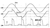
在图19所示的LED照明系统中,当三端双向可控硅开关元件Tra1处于断开状态时,会切断从交流电源1至LED驱动电路101的电源;然而,交流电源1和LED驱动电路101一直通过上述相位控制调光控制器2的噪声防止电路的电容C1彼此相连。因此,即使三端双向可控硅开关元件Tra1处于断开状态,还是如图20A和20B所示那样向LED提供电流。这里,在图20A和20B中,VIN2是相位控制调光控制器2的输入电压波形VOUT2是来自相位控制调光控制器2的输出电压波形;而I3是流入LED模块3的电流波形。In the LED lighting system shown in Figure 19, when the triac Tra1 is in the off state, it will cut off the power from the
由于相位控制发光控制器2的三端双向可控硅开关元件Tra1处于断开状态,因此仅向LED驱动电路101提供流过电容器C1的漏电流,由此LED驱动电路101的限流电路不工作;然而,存在漏电流使LED3导通并少量发光的问题。此外,由于LED模块3因流过电容C1的漏电流而少量发光,因此在LED模块3中产生正向电压VF;因此,在图20A中,三端双向可控硅开关元件Tra1的上升电压被延迟,且使驱动电流提供给LED模块3的时间长度变短,由此产生LED模块3变得暗淡且调光控制范围变窄的问题。Since the triac Tra1 of the phase
此外,作为LED照明系统的另一传统示例(该照明系统能够实现使用交流电源的LED发光器件的调光控制,如图21所示),存在一种照明系统,其包括相位控制调光控制器2’,该调光控制器2’具有借助氖灯的荧光功能。这里,在图21中,用相同附图标记表示与图19相同的部件,并省去其说明。Furthermore, as another conventional example of an LED lighting system capable of dimming control of an LED light emitting device using an AC power source, as shown in FIG. 21 , there is a lighting system including a phase control dimming controller 2', the dimming controller 2' has a fluorescent function by means of a neon lamp. Here, in FIG. 21 , the same components as those in FIG. 19 are denoted by the same reference numerals, and description thereof will be omitted.
在图21所示LED发光系统中,氖灯NL1和限流电阻Re1的串联电路(在下文中称其为荧光电路)并联于三端双向可控硅开关元件Tra1;如果通过外部开关S1选择三端双向可控硅开关元件Tra1以将LED驱动电流提供给LED模块3,则使氖灯NL1断电;如果通过开关S1选择荧光电路且不将LED驱动电流提供给LED模块3,则将电流提供给荧光电路以表示相位控制调光控制器2’所在的位置。如同在图21所示的LED照明系统中,即使噪声防止电路的电容C1不并联于三端双向可控硅开关元件Tra1,当三端双向可控硅开关元件Tra1处于断开状态时,也会有少量电流通过荧光电路提供给LED驱动电路101;因此,出现的问题是LED模块3少量发光,且延迟了三端双向可控硅开关元件Tra1的上升电压。In the LED lighting system shown in Figure 21, the series circuit of the neon lamp NL1 and the current limiting resistor Re1 (hereinafter referred to as the fluorescent circuit) is connected in parallel with the triac Tra1; if the triac is selected by the external switch S1 The bidirectional thyristor switching element Tra1 provides the LED driving current to the
这里,作为上述问题的解决方案,已知一种解决方案,其中如图22所示,通过使阻抗Z1(电阻、电容、氖灯等)并联于LED驱动电路102的功率输入部分(例如JP-A-2004-296205)来抑制流入LED模块3中的漏电流。然而,在图22所示的结构中,即使在三端双向可控硅开关元件Tra1导通且将输入电源提供给LED驱动电路102的时候,电流IZ1(=输入电源电压VZ1/阻抗Z1的阻抗值ZZ1)也流过阻抗Z1。因此,出现的问题是功率损耗大且功率效率降低。Here, as a solution to the above-mentioned problem, a solution is known in which, as shown in FIG. A-2004-296205) to suppress the leakage current flowing into the
发明概述Summary of the invention
本发明的第一目的是提供一种能够防止LED不必要发光且功率效率高的LED驱动电路、LED照明器件、LED照明设备和LED照明系统。A first object of the present invention is to provide an LED driving circuit, an LED lighting device, an LED lighting device, and an LED lighting system capable of preventing unnecessary light emission of LEDs and having high power efficiency.
第二目的是提供一种能够防止LED不必要发光的LED照明器件、LED照明设备和LED照明系统。The second object is to provide an LED lighting device, LED lighting equipment and LED lighting system capable of preventing unnecessary light emission of LEDs.
为了实现上述第一目的,根据本发明的LED驱动电路是接收交流电压以驱动LED的LED驱动电路,并包括将从提供LED驱动电流至LED的供电线的电流撤除的电流撤除部分。如果至LED驱动电路的输入电流是不必要的电流,则由于电流撤除部分的电流撤除而LED不发光。如果至LED驱动电路的输入电流从不必要电流转变为LED驱动电流,则电流撤除部分减小撤除的电流量。这里,不必要的电流表示可以提供给LED的、在需要使LED保持发光的时间周期内对LED来说是不必要的电流;LED驱动电流表示在必须使LED保持发光的时间周期内提供给LED的电流。In order to achieve the above first object, an LED driving circuit according to the present invention is an LED driving circuit that receives an AC voltage to drive LEDs, and includes a current withdrawal part that removes current from a power supply line supplying LED driving current to the LEDs. If the input current to the LED driving circuit is an unnecessary current, the LED does not emit light due to the current withdrawal of the current withdrawal portion. If the input current to the LED driving circuit changes from unnecessary current to LED driving current, the current shedding portion reduces the amount of current shed. Here, unnecessary current refers to the current that can be supplied to the LED, which is unnecessary for the LED during the time period required to keep the LED glowing; LED drive current refers to the current supplied to the LED during the time period necessary to keep the LED glowing. current.
根据这种结构,如果根据本发明的至LED驱动电路的输入电流是不必要的电流,则由于电流撤除部分的电流撤除而LED不发光;因此,可防止LED发生不必要的发光。此外,如果至LED驱动电路的输入电流从不必要的电流转变为LED驱动电流,则电流撤除部分减少撤除的电流量;因此,在根据本发明的至LED驱动电路的输入电流是LED驱动电流时,可减小功率损耗并提高功率效率。According to this structure, if the input current to the LED driving circuit according to the present invention is an unnecessary current, the LED does not emit light due to the current withdrawal of the current withdrawal portion; therefore, unnecessary light emission of the LED can be prevented. In addition, if the input current to the LED driving circuit changes from an unnecessary current to the LED driving current, the current withdrawal part reduces the amount of current withdrawn; therefore, when the input current to the LED driving circuit according to the present invention is the LED driving current , can reduce power loss and improve power efficiency.
电流撤除部分可包括:承载从电流供给线撤除的电流的旁路线;设置在旁路线上的有源元件以及控制有源元件的控制部分。如果至LED驱动电路的输入电流从不必要电流转变为LED驱动电流,则控制部分可将有源元件的状态从导通状态切换至截止状态。The current withdrawal part may include: a bypass line carrying current withdrawn from the current supply line; an active element disposed on the bypass line; and a control part controlling the active element. If the input current to the LED driving circuit changes from unnecessary current to LED driving current, the control part may switch the state of the active element from the on state to the off state.
根据这种结构,如果至LED驱动电路的输入电流从不必要电流转变为LED驱动电流,则有源元件从导通状态切换至截止状态,因此可防止电流流入旁路线。此外,由于控制部分产生用于控制有源元件的控制信号,当有源元件处于导通状态时,流入控制部分的电流远小于流入旁路线的电流。因此,如果至LED驱动电路的输入电流从不必要电流转变为LED驱动电流,则根据本发明的LED驱动电路的电流撤除部分能够减小所撤除的电流量。According to this structure, if the input current to the LED driving circuit changes from unnecessary current to LED driving current, the active element is switched from the on state to the off state, so the current can be prevented from flowing into the bypass line. In addition, since the control part generates a control signal for controlling the active element, when the active element is in the on state, the current flowing into the control part is much smaller than the current flowing into the bypass line. Therefore, if the input current to the LED driving circuit changes from unnecessary current to LED driving current, the current shedding part of the LED driving circuit according to the present invention can reduce the amount of current that is shed.
此外,可包括用于限制流入LED的电流的限流电路。Additionally, a current limiting circuit for limiting the current flowing into the LED may be included.
可包括用于对LED驱动电路的输入电压进行整流的整流电路。A rectification circuit for rectifying the input voltage of the LED driving circuit may be included.
可包括用来检测至LED驱动电路的输入电压或通过对输入电压整流而获得电压的电压检测电路;且控制部分可根据来自电压检测电路的检测结果来控制有源元件。此外,可采用一种结构,其中电压检测部分包括多个分压电阻。控制部分可包括将来自电压检测部分的检测结果与设定电压进行比较的比较器,并根据来自比较器的比较结果控制有源元件。此外,从更高功率效率的角度看,比较器可具有磁滞特性。A voltage detection circuit for detecting an input voltage to the LED driving circuit or a voltage obtained by rectifying the input voltage may be included; and the control section may control the active element according to a detection result from the voltage detection circuit. In addition, a structure may be employed in which the voltage detecting section includes a plurality of voltage dividing resistors. The control part may include a comparator that compares a detection result from the voltage detection part with a set voltage, and controls the active element according to the comparison result from the comparator. Also, from the standpoint of higher power efficiency, the comparator may have a hysteresis characteristic.
控制部分可包括:第一晶体管,其基极连接于电压检测电路的输出;以及连接于第一晶体管的集电极的恒流源或电阻。而有源元件可以是第二晶体管,其基极连接于第一晶体管的集电极。The control part may include: a first transistor, the base of which is connected to the output of the voltage detection circuit; and a constant current source or a resistor connected to the collector of the first transistor. The active element may instead be a second transistor, the base of which is connected to the collector of the first transistor.
控制部分可包括:晶闸管,其栅极连接于电压检测电路的输出;以及连接于晶闸管阳极的恒流源或电阻。而有源元件可以是晶体管,其基极连接于晶闸管的阳极。The control part may include: a thyristor, the gate of which is connected to the output of the voltage detection circuit; and a constant current source or a resistor connected to the anode of the thyristor. The active element can instead be a transistor whose base is connected to the anode of a thyristor.
该控制部分可包括:第一N沟道MOS晶体管,其栅极连接于电压检测电路的输出;以及连接于第一N沟道MOS晶体管的漏极的恒流源或电阻。而有源元件可以是第二N沟道MOS晶体管,其栅极连接于第一N沟道MOS晶体管的漏极。The control part may include: a first N-channel MOS transistor having a gate connected to the output of the voltage detection circuit; and a constant current source or a resistor connected to a drain of the first N-channel MOS transistor. And the active element may be a second N-channel MOS transistor, the gate of which is connected to the drain of the first N-channel MOS transistor.
可包括用于检测至LED驱动电路的输入电流或通过对输入电流进行整流而获得的电流的电流检测电路;且控制部分可根据来自电流检测电路的检测结果控制有源元件。此外,电流检测电路可包括:电流检测电阻;以及用于检测跨越电流检测电阻两个端子的电压的放大器。A current detection circuit for detecting an input current to the LED drive circuit or a current obtained by rectifying the input current may be included; and the control section may control the active element according to a detection result from the current detection circuit. In addition, the current detection circuit may include: a current detection resistor; and an amplifier for detecting a voltage across two terminals of the current detection resistor.
电流撤除部分可单独设置在交流电压的两个方向上。The current withdrawal section can be separately provided in both directions of the AC voltage.
可包括用于接收外部信号的外部信号输入部分;且该控制部分可根据外部信号控制有源元件。An external signal input part for receiving an external signal may be included; and the control part may control the active element according to the external signal.
为了达到上述第一目的,如此构造根据本发明的LED照明器件使之包括:具有任何一种上述结构的LED驱动电路;以及连接于LED驱动电路的输出侧的LED。In order to achieve the above-mentioned first object, the LED lighting device according to the present invention is constructed so as to include: an LED driving circuit having any one of the above-mentioned structures; and an LED connected to an output side of the LED driving circuit.
为了达到上述第二目的,如此构造根据本发明的LED照明器件使之包括:LED;以及防止LED由于不必要电流而发光的LED发光防止部分。此外,可包括抑制因LED发光防止部分造成的功率损耗的功率损耗抑制部分。In order to achieve the above-mentioned second object, the LED lighting device according to the present invention is so constructed as to include: an LED; and an LED light emission preventing portion that prevents the LED from emitting light due to unnecessary current. In addition, a power loss suppressing section that suppresses power loss due to the LED light emission preventing section may be included.
根据这种结构,例如在传统地使用例如白炽灯、荧光灯等照明器件的已有照明设备和照明系统中,仅通过用根据本发明的LED照明器件代替例如白炽灯、荧光灯等照明器件就可防止LED由于不必要电流而发光。此外,可通过设置抑制由LED发光防止部分产生的功率损耗的功率损耗抑制部分而提高功率效率。According to this structure, for example, in existing lighting equipment and lighting systems that conventionally use lighting devices such as incandescent lamps and fluorescent lamps, it is possible to prevent LEDs glow due to unnecessary current. Furthermore, power efficiency can be improved by providing a power loss suppressing section that suppresses power loss generated by the LED light emission preventing section.
为了达到上述第一或第二目的,如此构造根据本发明的LED照明设备使之包括具有任何一种上述结构的LED照明器件。In order to achieve the above-mentioned first or second object, the LED lighting device according to the present invention is constructed so as to include the LED lighting device having any one of the above-mentioned structures.
此外,为了达成上述第一或第二目的,根据本发明的LED照明系统包括:具有任何一种上述结构的LED照明器件或具有上述结构的LED照明设备;以及连接于LED照明器件或LED照明设备的LED驱动电路的输入侧的调光控制器。In addition, in order to achieve the above-mentioned first or second purpose, the LED lighting system according to the present invention includes: an LED lighting device with any of the above-mentioned structures or an LED lighting device with the above-mentioned structure; The dimming controller on the input side of the LED drive circuit.
附图说明 Description of drawings
图1是示出根据本发明的LED照明系统的一个结构例的示图。FIG. 1 is a diagram showing a configuration example of an LED lighting system according to the present invention.
图2是示出根据本发明的图1所示的LED照明系统的一个实施例的示图。FIG. 2 is a diagram showing one embodiment of the LED lighting system shown in FIG. 1 according to the present invention.
图3是示出根据本发明的图2所示的LED照明系统的第一实施例的示图。FIG. 3 is a diagram showing a first embodiment of the LED lighting system shown in FIG. 2 according to the present invention.
图4是示出根据本发明的图3所示的LED照明系统的特定例的示图。FIG. 4 is a diagram showing a specific example of the LED lighting system shown in FIG. 3 according to the present invention.
图5是示出用具有磁滞功能的比较器替代根据本发明的图4所示的LED照明系统的比较器的结构的示图。FIG. 5 is a diagram showing the structure of replacing the comparator of the LED lighting system shown in FIG. 4 according to the present invention with a comparator having a hysteresis function.
图6是示出根据本发明的图3所示的LED照明系统的另一特定例的示图。FIG. 6 is a diagram showing another specific example of the LED lighting system shown in FIG. 3 according to the present invention.
图7是示出用电阻代替根据本发明的图6所示的LED照明系统的恒流源的结构的示图。FIG. 7 is a diagram showing a structure in which a constant current source of the LED lighting system shown in FIG. 6 according to the present invention is replaced by a resistor.
图8A是示出图4-7所示的特定例中的工作波形的示例的图。Fig. 8A is a diagram showing an example of an operation waveform in the specific example shown in Figs. 4-7.
图8B是示出图4-7所示的特定例中的工作波形的示例的图。Fig. 8B is a diagram showing an example of an operation waveform in the specific example shown in Figs. 4-7.
图8C是示出图4-7所示的特定例中的工作波形的示例的图。Fig. 8C is a diagram showing an example of an operation waveform in the specific example shown in Figs. 4-7.
图9是示出根据本发明的图3所示的LED照明系统的另一特定例的示图。FIG. 9 is a diagram showing another specific example of the LED lighting system shown in FIG. 3 according to the present invention.
图10是示出根据本发明的在图3所示的LED照明系统中使用MOS晶体管的特定例的图。FIG. 10 is a diagram showing a specific example of using a MOS transistor in the LED lighting system shown in FIG. 3 according to the present invention.
图11是示出根据本发明的图2所示的LED照明系统的第二实施例的图。FIG. 11 is a diagram showing a second embodiment of the LED lighting system shown in FIG. 2 according to the present invention.
图12是示出根据本发明的图11所示的LED照明系统的特定例的图。Fig. 12 is a diagram showing a specific example of the LED lighting system shown in Fig. 11 according to the present invention.
图13是示出其中设置具有彼此不同的正方向的两个LED模块的LED照明系统的结构例的图。FIG. 13 is a diagram illustrating a configuration example of an LED lighting system in which two LED modules having different forward directions from each other are provided.
图14是示出根据本发明的包含外部信号输入部分的LED照明系统的结构例的图。Fig. 14 is a diagram showing a configuration example of an LED lighting system including an external signal input section according to the present invention.
图15是示出限流电路的结构例的图。FIG. 15 is a diagram showing a configuration example of a current limiting circuit.
图16是示出包含开关和荧光电路的调光控制器的图。Fig. 16 is a diagram showing a dimming controller including a switch and a fluorescent circuit.
图17是示出根据本发明的LED照明器件的示意性结构例的图。Fig. 17 is a diagram showing a schematic configuration example of an LED lighting device according to the present invention.
图18是根据本发明的LED照明器件的另一示意性结构例的图。Fig. 18 is a diagram of another schematic structural example of the LED lighting device according to the present invention.
图19是示出能够对使用交流电源的LED照明器件进行调光控制的LED照明系统的传统例的图。Fig. 19 is a diagram showing a conventional example of an LED lighting system capable of dimming control of an LED lighting device using an AC power source.
图20A是示出相位控制调光控制器的输入电压和流入LED的电流的波形的图。FIG. 20A is a diagram showing waveforms of an input voltage of a phase control dimming controller and a current flowing into an LED.
图20B是示出相位控制调光控制器的输入电压和流入LED的电流的波形的图。FIG. 20B is a diagram showing waveforms of an input voltage of a phase control dimming controller and a current flowing into an LED.
图21是示出能够对使用交流电源的LED照明器件进行调光控制的LED照明系统的另一传统例的图。Fig. 21 is a diagram showing another conventional example of an LED lighting system capable of dimming control of an LED lighting device using an AC power source.
图22是示出含抑制流入LED的不必要电流的装置的LED照明系统的传统例的图。Fig. 22 is a diagram showing a conventional example of an LED lighting system including a device for suppressing unnecessary current flowing into an LED.
较佳实施例的说明Description of the preferred embodiment
下面结合附图对本发明的实施例进行说明。根据本发明的LED照明系统的结构例示出于图1中。根据图1所示的本发明的LED照明系统包括:相位控制调光控制器2、根据本发明的LED驱动电路100以及LED模块3。在根据图1所示的本发明的LED照明系统中,交流电源1、相位控制调光控制器2和根据本发明的LED驱动电路100彼此串联。包括一个或多个LED的LED模块3的阳极和阴极连接于根据本发明的LED驱动电路100的输出侧。Embodiments of the present invention will be described below in conjunction with the accompanying drawings. A structural example of an LED lighting system according to the present invention is shown in FIG. 1 . The LED lighting system according to the present invention shown in FIG. 1 includes: a phase
即使三端双向可控硅开关元件tra1处于截止状态,与交流电源1的频率(50Hz或60Hz)对应的电流也会从相位控制调光控制器2的噪声防止电路的电容C1流至根据本发明的LED驱动电路100。Even if the triac tra1 is in an off state, a current corresponding to the frequency (50 Hz or 60 Hz) of the
根据本发明的LED驱动电路100包括将电流从向LED模块3提供LED驱动电流的供电线撤除的电流撤除部分(未示出)。如果至根据本发明的LED驱动电路100的输入电流是不必要电流,则LED模块3由于电流撤除部分的电流撤除而不发光;如果至根据本发明的LED驱动电路100的输入电流从不必要电流转变为LED驱动电流,则电流撤除部分减少所撤除的电流量。这里,不必要电流表示能够提供给LED模块3的、在需要使LED模块3保持发光的时间间隔内对LED模块3来说不是必要的电流;这里,来自电容C1的漏电流是不必要电流。LED驱动电路表示在需要使LED模块3保持发光的时间间隔内提供给LED模块3的电流。The
如果根据本发明的LED驱动电路100的输入电流为不必要电流,则LED模块3由于电流撤除部分的电流撤除而不发光;从而防止LED模块3产生不必要的发光。此外,如果至LED驱动电路100的输入电流从不必要电流转变为LED驱动电流,则电流撤除部分减小所撤除电流的量,从而当流至根据本发明的LED驱动电路100的输入电流是LED驱动电流时可减小功率损耗并提高功率效率。If the input current of the
接着,图2中示出根据本发明的图1所示的LED照明系统的一个实施例。在根据图2所示本发明的LED照明系统中,根据本发明的LED驱动电路100的电流撤除部分包括:承载从电流供给线撤除的电流的旁路线BL1;设置在旁路线BL1上的有源元件11以及控制有源元件11的控制部分12。如果至根据本发明的LED驱动电路100的输入电流从不必要电流转变为LED驱动电流,则控制部分12将有源元件11的状态从导通状态切换至截止状态。这里,在图2中,在根据本发明的LED驱动电路100中,尽管未示出电流撤除部分以外的组成部件,然而根据本发明的LED驱动电路100可包括任何组成部件。Next, FIG. 2 shows an embodiment of the LED lighting system shown in FIG. 1 according to the present invention. In the LED lighting system according to the present invention shown in FIG. 2 , the current removal part of the
在根据图2所示的本发明的LED照明系统中,如果至根据本发明的LED驱动电路100的输入电流从不必要电流转变为LED驱动电流,则有源元件11从导通状态切换至截止状态;从而可防止电流流入旁路线BL1。由于控制部分12产生用于控制有源元件11的控制信号,因此流入控制部分12的电流远小于当有源元件11处于导通状态时流入旁路线BL1的电流。因此,如果至根据本发明的LED驱动电路100的输入电流从不必要电流转变为LED驱动电流,则根据本发明的LED驱动电路100的电流撤除部分能够减少所撤除的电流量。In the LED lighting system according to the present invention shown in FIG. 2, if the input current to the
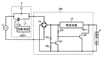
接着,根据本发明的图2所示LED照明系统的第一实施例示出于图3中。在根据图3所示本发明的LED照明系统中,根据本发明的LED驱动电路100包括:桥接二极管13,其对加至根据本发明的LED驱动电路100的输入电压进行整流;限流电路14,其限制流至LED模块3的电流;以及电压检测电路15,其检测来自桥接二极管13的输出电压。从交流电源1输出且相位受到控制的——即受相位控制调光控制器2相位控制的——电压被全波整流,即由桥接二极管13全波整流,并经由限流电路14施加于LED模块3。控制部分12根据来自电压检测电路15的检测结果来执行有源元件11的导通/截止控制。Next, a first embodiment of the LED lighting system shown in FIG. 2 according to the present invention is shown in FIG. 3 . In the LED lighting system according to the present invention shown in FIG. 3 , the
接着,根据本发明图3所示的LED照明系统的特定例示出于图4中。在图4中,电压检测电路15由分压电阻R1和R2构成,控制部分12由比较器COMP1和恒压源VS1构成。Next, a specific example of the LED lighting system shown in FIG. 3 according to the present invention is shown in FIG. 4 . In FIG. 4, the
比较器COMP1将分压电阻R1、R2之间的中点电压与从恒压源VS1输出的恒定电压进行比较;在分压电阻R1和R2之间的中点电压小于从恒压源VS1输出的恒定电压期间,使有源元件11保持在导通状态;通过防止漏电流流入LED模块3而阻止LED模块3发光;并在分压电阻R1和R2之间的中点电压等于或大于从恒压源VS1输出的恒定电压期间,使有源元件11保持在截止状态,从而防止电流流入旁路线BL1。The comparator COMP1 compares the midpoint voltage between the voltage dividing resistors R1 and R2 with the constant voltage output from the constant voltage source VS1; the midpoint voltage between the voltage dividing resistors R1 and R2 is smaller than the output from the constant voltage source VS1 During the constant voltage period, the
通过改变分压电阻R1和R2的电阻比,可改变比较器COMP1的门限电压,并还有可能改变有源元件11的导通/截止切换定时。By changing the resistance ratio of the voltage dividing resistors R1 and R2, the threshold voltage of the comparator COMP1 can be changed, and also the on/off switching timing of the
比较器COMP1的门限电压在两种情形下相等:分压电阻R1和R2之间的中点电压小于从恒压源VS1输出的恒定电压的状态转变为分压电阻R1和R2之间的中点电压大于从恒压源VS1输出的恒定电压的状态;分压电阻R1和R2之间的中点电压大于从恒压源VS1输出的恒定电压的状态转变为分压电阻R1和R2之间的中点电压小于从恒压源VS1输出的恒定电压的状态。因此,当从交流电源1输出的交流电压从峰值141V降低至0V时,有源元件11不时地导通,由此对LED模块3发光不起作用的电流流入旁路线BL1。为了避免这点,如图5所示,使用具有磁滞特性的比较器COMP2来代替比较器COMP1;且把在分压电阻R1和R2之间的中点电压大于从恒压源VS1输出的恒定电压的状态改变至分压电阻R1和R2之间的中点电压小于从恒压源VS1输出的恒定电压的状态期间的门限电压设置为低于在分压电阻R1和R2之间的中点电压小于从恒压源VS1输出的恒定电压的状态转变至分压电阻R1和R2之间的中点电压大于从恒压源VS1输出的恒定电压的状态期间的门限电压。因此,当从交流电源1输出的交流电压从峰值141V降低至0V时,可防止有源元件11导通,并防止对LED模块3的发光不起作用的电流流入旁路线BL1,以使功率效率进一步提高。The threshold voltage of the comparator COMP1 is equal in two situations: the midpoint voltage between the voltage dividing resistors R1 and R2 is less than the state transition of the constant voltage output from the constant voltage source VS1 to the midpoint between the voltage dividing resistors R1 and R2 The state where the voltage is greater than the constant voltage output from the constant voltage source VS1; the state where the midpoint voltage between the voltage dividing resistors R1 and R2 is greater than the constant voltage output from the constant voltage source VS1 changes to the middle point between the voltage dividing resistors R1 and R2 A state where the point voltage is lower than the constant voltage output from the constant voltage source VS1. Therefore, when the AC voltage output from the
根据本发明的图3所示LED照明系统的另一特定例子示出于图6中。在图6中,电压检测电路15由分压电阻R1和R2构成。控制部分12包括:第一晶体管Q1,其基极连接于由分压电阻R1和R2构成的电压检测电路的输出;以及连接于晶体管Q1的集电极的恒流源IS1。有源元件11充当第二晶体管Q2。Another specific example of the LED lighting system shown in FIG. 3 according to the present invention is shown in FIG. 6 . In FIG. 6, the
由于在分压电阻R1和R2之间的中点电压小于晶体管Q1的基极-发射极电压时晶体管Q1处于截止状态,来自恒流源IS1的电流被提供给晶体管Q2的基极,且晶体管Q2导通。因此,漏电流不流入LED模块3且LED模块3不发光。另一方面,由于在分压电阻R1、R2之间的中点电压等于或大于晶体管Q1的基极-发射极电压时晶体管Q1处于导通状态,来自恒流源IS1的电流不被提供给晶体管Q2的基极,且晶体管Q2截止。因此,电流不流入旁路线BL1。Since the transistor Q1 is in an off state when the midpoint voltage between the voltage dividing resistors R1 and R2 is smaller than the base-emitter voltage of the transistor Q1, the current from the constant current source IS1 is supplied to the base of the transistor Q2, and the transistor Q2 conduction. Therefore, leakage current does not flow into the
可通过改变分压电阻R1和R2的电阻比而改变晶体管Q2的导通/截止切换定时。此外,如果通过设定恒流源IS1的恒电流值和晶体管Q2的h参数hFE而使晶体管Q2的集电极-发射极电压足够小,则可抑制三端双向可控硅开关元件Tra1的上升电压的延迟。The on/off switching timing of the transistor Q2 can be changed by changing the resistance ratio of the voltage dividing resistors R1 and R2. In addition, if the collector-emitter voltage of the transistor Q2 is made small enough by setting the constant current value of the constant current source IS1 and the h parameter hFE of the transistor Q2, the rising of the triac Tra1 can be suppressed. voltage delay.
此外,图6所示结构中的恒流源IS1可用电阻R3代替而实现图7所示结构。相比图6所示结构,图7所示结构能够获得控制部分的简化和成本降低。In addition, the constant current source IS1 in the structure shown in FIG. 6 can be replaced by a resistor R3 to realize the structure shown in FIG. 7 . Compared with the structure shown in FIG. 6, the structure shown in FIG. 7 can achieve simplification and cost reduction of the control part.
这里,图4-7所示特定例中的工作波形的例子示出于图8A-8C中。在图8A-8C中,VIN2是相位控制调光控制器2的输入电压波形;VOUT2是来自相位控制调光控制器2的输出电压波形;而I3是流入LED模块3的电流波形。图8A示出100%调光控制(无相位延迟)的波形;图8B示出半调光控制(具有一半相位延迟)的波形;而图8C示出0%调光控制(具有最大相位延迟)——即处于截止状态——的波形。Here, examples of operating waveforms in the specific examples shown in FIGS. 4-7 are shown in FIGS. 8A-8C. In FIGS. 8A-8C , V IN2 is the input voltage waveform of the phase
如从图8A-8C可清楚地看出,如果交流电源1、相位控制调光控制器2和根据本发明的LED驱动电路100彼此串联,并驱动LED模块3,则可通过相位控制调光控制器2来实现LED模块3从100%-0%发光的调光控制。而不必要电流不包含在流入LED模块3的电流I3中。此外,即使用含氖灯的具有荧光功能的相位控制调光控制器2’代替相位控制调光控制器2,同样可通过相位控制调光控制器2’来实现LED模块3从100%-0%发光的调光控制,且不必要电流不包含在流入LED模块3的电流I3中。As can be clearly seen from Figures 8A-8C, if the
接下来,根据本发明的图3所示的LED照明系统的又一特定例示出于图9。在图9中,电压检测电路15由分压电阻R1和R2构成。控制部分12包括:晶闸管Tha1,其栅极连接于由分压电阻R1和R2构成的电压检测电路的输出;以及电阻R3,其连接于晶闸管Tha1的阳极。有源元件11充当第二晶体管Q2。此外,在旁路线BL1上设置连接于晶体管Q2的发射极的多个二极管D1-Dn。Next, another specific example of the LED lighting system shown in FIG. 3 according to the present invention is shown in FIG. 9 . In FIG. 9, the
由于晶闸管Tha1在分压电阻R1和R2之间的中点电压小于晶闸管Tha1的栅极电压时处于截止状态,从电阻R3——即电流源——流出的电流被提供给晶体管Q2的基极,且晶体管Q2导通。因此,漏电流不流入LED模块3,且LED模块3不发光。另一方面,由于晶闸管Tha1在分压电阻R1、R2之间的中点电压等于或大于晶闸管Tha1的栅极电压时处于导通状态,从电阻R3——即电流源——流出的电流不被提供给晶体管Q2的基极,且晶体管Q2截止。因此,电流不流入旁路线BL1。Since the thyristor Tha1 is in the off state when the midpoint voltage between the voltage dividing resistors R1 and R2 is less than the gate voltage of the thyristor Tha1, the current flowing from the resistor R3, which is the current source, is supplied to the base of the transistor Q2, And the transistor Q2 is turned on. Therefore, leakage current does not flow into the
由于图9所示的结构使用晶闸管Tha1而不是图6或图7中的晶体管Q1,通过使用晶闸管Tha1,可进一步抑制功率损耗并提高功率效率。换句话说,当从交流电源1输出的交流电压从峰值141V下降至0V时产生的来自晶体管Q2的输出电压(集电极-发射极电压)受到晶闸管Tha1的电流保持功能的抑制。尽管晶闸管Tha1象晶体管Q1那样在触发电压下进入导通状态,即使触发电压停止,导通电流也可在交流电源1的输出交流电压的半个周期内保持流动。因此,晶体管Q2的基极-发射极电压保持在低电平,因此晶体管Q2能够保持截止状态。连接于晶体管Q2发射极的多个二极管D1-Dn是晶体管Q2的控制的一个例子,其中使晶体管Q2的发射极电位高于晶闸管Tha1的导通电压(一般大约为1.4V),且晶体管Q2受晶闸管Tha1的导通/截止的控制。可通过其它方法使晶体管Q2的发射极电位较高。Since the structure shown in FIG. 9 uses the thyristor Tha1 instead of the transistor Q1 in FIG. 6 or 7, by using the thyristor Tha1, power loss can be further suppressed and power efficiency can be improved. In other words, the output voltage (collector-emitter voltage) from transistor Q2 generated when the AC voltage output from
接着,根据本发明的将MOS晶体管用于图3所示LED照明系统的特定例示出于图10。图10所示结构是通过用第一N沟道MOS晶体管Q3代替第一晶体管Q1,并通过用图7所示结构中的第二N沟道MOS晶体管Q4代替第二晶体管Q2而获得的,并取得与图7所示结构相同的功能。Next, a specific example of using a MOS transistor for the LED lighting system shown in FIG. 3 according to the present invention is shown in FIG. 10 . The structure shown in FIG. 10 is obtained by replacing the first transistor Q1 with a first N-channel MOS transistor Q3, and by replacing the second transistor Q2 with a second N-channel MOS transistor Q4 in the structure shown in FIG. 7, and The same function as the structure shown in Fig. 7 is obtained.
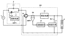
接着,根据本发明的图2所示LED照明系统的第二实施例示出于图11。在根据本发明的图11所示的LED照明系统中,根据本发明的LED驱动电路100包括:桥接二极管13,其对根据本发明的LED驱动电路100的输入电压进行整流;限流电路14,其限制流入LED模块3的电流;以及电流检测电路16,其检测来自桥接二极管13的输出电流。从交流电源1输出且相位受控的——即受相位控制调光控制器2相位控制的——电压被全波整流,即通过桥接二极管13全波整流并经由限流电路14施加于LED模块3。控制部分12根据来自电流检测电路16的检测结果执行有源元件11的导通/截止控制。如图12所示,作为电流检测电路16的一个例子,存在一种电流检测电路,包括:电流检测电阻器R4;以及误差放大器AMP1,其检测跨越电流检测电阻R4两个端子的电压。这里,第二实施例中的有源元件11、控制电路12和限流电路14的特定示例示出于图11,可以使用在上述第一实施例中的有源元件11、控制电路12和限流电路14的特定例。Next, a second embodiment of the LED lighting system shown in FIG. 2 according to the present invention is shown in FIG. 11 . In the LED lighting system shown in FIG. 11 according to the present invention, the
与上述LED照明系统的类型不同,存在一种类型的LED照明系统,其中设有正向彼此不同的两个LED模块,;且发光、发光控制和导通/截止控制是在交流电的半个周期内完成的。这种类型的LED照明系统的优点在于:不需要桥接二极管;由于不需要桥接二极管而使功率效率略为提高;且由于LED驱动电路的占空比只占全波整流后驱动的类型的一半,LED的寿命延长(光通量下降得以缓解)。然而,另一方面,存在的缺点是由于LED数目加倍而增加了成本。根据本发明的LED照明系统的一个结构例示出于图13,其中设有正向彼此不同的两个LED模块。与图3所示结构相同,在图13所示结构中,LED模块3A包括:旁路线BL1A;有源元件11A;控制部分12A;限流电路14A以及电压检测电路15A。此外,LED模块3B包括:旁路线BL1B;有源元件11B;控制部分12B;限流电路4B以及电压检测电路15B。据此,能象根据本发明的图3所示照明系统那样驱动照明系统而无需对交流电压进行整流。Unlike the above-mentioned types of LED lighting systems, there is a type of LED lighting system in which two LED modules whose forward directions are different from each other are provided; completed within. The advantages of this type of LED lighting system are: no bridge diodes are required; power efficiency is slightly improved due to the absence of bridge diodes; The life of the LED is extended (the decrease in luminous flux is alleviated). On the other hand, however, there is a disadvantage of increased cost due to doubling the number of LEDs. A structural example of the LED lighting system according to the present invention is shown in FIG. 13, in which two LED modules having different front directions from each other are provided. Same as the structure shown in FIG. 3 , in the structure shown in FIG. 13 , the
接着,根据本发明的LED照明系统的一个结构例示出于图14,其包括外部信号输入部分。图14所示的结构是这样一种结构,它包括:外部信号输入端子17而不是图3所示结构中的电压检测电路15;以及根据外部信号输入端子17的外部信号输入执行有源元件11的导通/截止控制的控制部分12。通过内建在简易微机或相位控制调光控制器中的例如控制电路CNT1等脉冲发生器产生外部信号,并被提供给外部信号输入端子17。根据这种类型,可方便地添加附加功能,例如在异常时间使LED截止的停机功能、定时器发光功能等。Next, a structural example of the LED lighting system according to the present invention is shown in FIG. 14, which includes an external signal input part. The structure shown in FIG. 14 is a structure that includes: an external
根据本发明的LED驱动电路的输入电压不局限于日本的100V市电电源电压。如果根据本发明的LED驱动电路的电路常数被设置在适当的值,则可将海外市电电源电压或降低的交流电压用作根据本发明的LED驱动电路的输入电压。The input voltage of the LED driving circuit according to the present invention is not limited to the 100V mains supply voltage in Japan. If the circuit constants of the LED driving circuit according to the present invention are set at appropriate values, overseas mains power supply voltage or reduced AC voltage can be used as the input voltage of the LED driving circuit according to the present invention.
此外,可通过将例如电流熔丝等保护性元件添加至根据本发明的LED驱动电路而提供更安全的LED驱动电路。Furthermore, a safer LED driving circuit can be provided by adding a protective element such as a current fuse to the LED driving circuit according to the present invention.
在LED驱动电路的上述结构中,尽管在限流电路的后级设置旁路线,然而也可在限流电路的前级(桥接二极管的输入侧或输出侧)设置旁路线。然而,在旁路线设置在限流电路的前级(桥接二极管的输入侧或输出侧)的情形下,需要确保设置在旁路线上的有源元件不受无限制电流的损坏。In the above structure of the LED drive circuit, although the bypass line is provided in the subsequent stage of the current limiting circuit, the bypass line may be provided in the preceding stage (input side or output side of the bridge diode) of the current limiting circuit. However, in the case where the bypass line is provided at the previous stage (input side or output side of the bridge diode) of the current limiting circuit, it is necessary to ensure that the active elements provided on the bypass line are not damaged by the unlimited current.
在LED驱动电路的上述结构(除了图13所示的结构)中,限流电路14连接于LED模块3的阳极侧。然而,如果适当地设定每个电路常数,则在将限流电路14连接于LED模块3的阴极侧方面不存在问题。In the above configurations of the LED driving circuit (except for the configuration shown in FIG. 13 ), the current limiting
限流电路14是防止等于或大于额定电流的电流流入LED模块的电路部分。存在仅通过例如电阻等无源元件或通过电阻与例如晶体管等有源元件的结合而限制电流(例如图15所示结构)的情形。The current limiting
此外,如果流入LED模块3的电流相对于LED的额定电流具有足够的裕度,则即使不设置限流电路也不会对调光控制操作等产生影响。In addition, if the current flowing into the
即使设置除相位控制调光控制器2和因氖灯而具有荧光发光功能的相位控制调光控制器2’以外的调光控制器,例如图16所示包括开关S1和荧光电路(氖灯NL1和限流电路Re1的串联电路)而取代相位控制调光控制器2和因氖灯而具有荧光发光功能的相位控制调光控制器2’,根据本发明的LED驱动电路是有效的,并且在这种情形下,可防止产生不必要的发光,并提高功率效率。Even if a dimming controller other than the phase
根据本发明的LED驱动电路的输入电压不局限于基于正弦波交流电压的电压,而是可使用其它交流电压。The input voltage of the LED driving circuit according to the present invention is not limited to a voltage based on a sine wave AC voltage, but other AC voltages may be used.
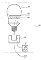
最后,描述根据本发明的LED照明器件的示意结构。根据本发明的LED照明器件的示意性结构例示出于图17。在图17中示出根据本发明的灯泡形LED照明器件200的局部剖视图。根据本发明的灯泡形LED照明器件200内包括:壳体或基板202;包括设置在壳体或基板202前表面(灯泡形状的上侧)上的一个或多个LED的LED模块201;以及设置在壳体或基板202后表面(灯泡形状的下侧)上的电路203。能够用根据本发明的上述LED驱动电路100作为电路203。电路203不局限于根据本发明的上述LED驱动电路100,当然,可使用包含至少一个电路(发光防止电路)的电路,该电路具有防止LED因不必要电流而发光的功能,且甚至还有功率损耗抑制功能以抑制由于发光防止电路的功率损耗。Finally, the schematic structure of the LED lighting device according to the present invention is described. A schematic structural example of the LED lighting device according to the present invention is shown in FIG. 17 . A partial cross-sectional view of a bulb-shaped
其中拧入和安装根据本发明的灯泡形LED照明器件200的LED照明器件安装部分300和控制器400与交流电源1串联。LED照明器件(顶灯、吊灯、厨房灯、嵌顶灯、落地灯、聚光灯、脚灯等)由根据本发明的灯泡形LED照明器件200和LED照明器件安装部分300构成。另外,根据本发明的LED照明系统500由根据本发明的灯泡形LED照明器件200、LED照明器件安装部分300和调光控制器400构成。LED照明器件安装部分300设置在例如居室的天花板壁上,而调光控制器400设置在例如居室的侧壁上。The LED lighting
由于根据本发明的灯泡形LED照明器件200是可拆卸地安装在LED照明器件安装部分300上的,例如,在传统地使用例如白炽灯、荧光灯等照明器件的已有照明设备和照明系统中,仅通过用根据本发明的灯泡形LED照明器件200代替例如白炽灯、荧光灯等照明器件就能防止LED由于不必要电流而发光。Since the bulb-shaped
在图17中示出调光控制器400是图1所示调光控制器2的情况中的调光控制器400的外观。换句话说,能够通过把手式调盘调整发光度。如果调光控制器400具有图16所示的结构,则调光控制器400的外观表现为例如与外部开关S1对应的按钮式开关,而不是把手式调盘。The appearance of the dimming
在上述描述中,描述了直接由人通过把手式调盘或按钮式开关操作的控制器作为调光控制器400。然而,这不构成限制,并且可采用由人通过无线电信号在远处操作的,例如,遥控器等控制器。具体地说,无线电信号接收部分设置在调光控制器主体上,即接收侧,而发送调光控制信号(例如亮度降低信号、光导通/截止信号等)至调光控制主体的无线电信号接收部分的无线电信号发送部分设置在发射器主体(例如遥控发射器、移动终端等),即发送侧,以使遥控操作变得可能。In the above description, the dimming
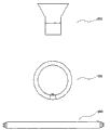
此外,根据本发明的LED照明器件不局限于灯泡形LED照明器件,例如,可采用图18所示的手电筒形LED照明器件600、环形LED照明器件700或直管形LED照明器件800。即使采用任何形状,根据本发明的LED照明器件内包括:LED;以及具有防止LED由于不必要电流而发光的功能的电路(发光保护电路)。此外,还希望设置其中具有功率损耗抑制功能的电路以抑制由于发光防止电路引起的功率损耗。In addition, the LED lighting device according to the present invention is not limited to a bulb-shaped LED lighting device, for example, a torch-shaped
Claims (17)
Applications Claiming Priority (2)
| Application Number | Priority Date | Filing Date | Title |
|---|---|---|---|
| JP2008263228A JP4943402B2 (en) | 2008-10-09 | 2008-10-09 | LED drive circuit, LED illumination lamp, LED illumination device, and LED illumination system |
| JP2008-263228 | 2008-10-09 |
Related Child Applications (1)
| Application Number | Title | Priority Date | Filing Date |
|---|---|---|---|
| CN201210270469.8A Division CN102821518B (en) | 2008-10-09 | 2009-09-04 | LED drive circuit, LED illumination component, led illumination device, and led illumination system |
Publications (2)
| Publication Number | Publication Date |
|---|---|
| CN101720150A CN101720150A (en) | 2010-06-02 |
| CN101720150B true CN101720150B (en) | 2013-07-10 |
Family
ID=42098238
Family Applications (2)
| Application Number | Title | Priority Date | Filing Date |
|---|---|---|---|
| CN2009101690075A Expired - Fee Related CN101720150B (en) | 2008-10-09 | 2009-09-04 | LED driving circuit, LED lighting device, LED lighting equipment and LED lighting system |
| CN201210270469.8A Expired - Fee Related CN102821518B (en) | 2008-10-09 | 2009-09-04 | LED drive circuit, LED illumination component, led illumination device, and led illumination system |
Family Applications After (1)
| Application Number | Title | Priority Date | Filing Date |
|---|---|---|---|
| CN201210270469.8A Expired - Fee Related CN102821518B (en) | 2008-10-09 | 2009-09-04 | LED drive circuit, LED illumination component, led illumination device, and led illumination system |
Country Status (4)
| Country | Link |
|---|---|
| US (2) | US8258706B2 (en) |
| JP (1) | JP4943402B2 (en) |
| KR (1) | KR101101223B1 (en) |
| CN (2) | CN101720150B (en) |
Families Citing this family (69)
| Publication number | Priority date | Publication date | Assignee | Title |
|---|---|---|---|---|
| US10655837B1 (en) | 2007-11-13 | 2020-05-19 | Silescent Lighting Corporation | Light fixture assembly having a heat conductive cover with sufficiently large surface area for improved heat dissipation |
| JP4943402B2 (en) * | 2008-10-09 | 2012-05-30 | シャープ株式会社 | LED drive circuit, LED illumination lamp, LED illumination device, and LED illumination system |
| US9713211B2 (en) | 2009-09-24 | 2017-07-18 | Cree, Inc. | Solid state lighting apparatus with controllable bypass circuits and methods of operation thereof |
| US8901829B2 (en) | 2009-09-24 | 2014-12-02 | Cree Led Lighting Solutions, Inc. | Solid state lighting apparatus with configurable shunts |
| US8901845B2 (en) | 2009-09-24 | 2014-12-02 | Cree, Inc. | Temperature responsive control for lighting apparatus including light emitting devices providing different chromaticities and related methods |
| US10264637B2 (en) | 2009-09-24 | 2019-04-16 | Cree, Inc. | Solid state lighting apparatus with compensation bypass circuits and methods of operation thereof |
| JP5366770B2 (en) * | 2009-11-18 | 2013-12-11 | 新電元工業株式会社 | Constant current power supply |
| US8476836B2 (en) * | 2010-05-07 | 2013-07-02 | Cree, Inc. | AC driven solid state lighting apparatus with LED string including switched segments |
| EP2386263B1 (en) * | 2010-05-11 | 2014-02-26 | Bien-Air Holding SA | Lighting module with light-emitting diodes for a surgical or dental handpiece |
| JP2012004175A (en) * | 2010-06-14 | 2012-01-05 | Casio Comput Co Ltd | Constant current circuit |
| CN102939795B (en) * | 2010-06-15 | 2016-11-09 | 马克西姆综合产品公司 | Dimmable offline LED driver |
| JP5126303B2 (en) * | 2010-07-01 | 2013-01-23 | ミツミ電機株式会社 | LIGHTING POWER DEVICE AND LIGHTING SYSTEM |
| CN102340904B (en) | 2010-07-14 | 2015-06-17 | 通用电气公司 | Light-emitting diode driving device and driving method thereof |
| JP5682949B2 (en) * | 2010-07-22 | 2015-03-11 | 新電元工業株式会社 | LED lighting device |
| EP2604093B1 (en) * | 2010-08-12 | 2015-03-25 | Huizhou Light Engine Ltd. | Led switching circuit for varying input voltage source |
| WO2012023635A1 (en) * | 2010-08-16 | 2012-02-23 | Lee Sang Chun | Light-emitting diode driver for phase control |
| AU2011293429B2 (en) * | 2010-08-27 | 2014-01-16 | Elemedia Tech Of America, Llc | Solid state lighting driver with THDi bypass circuit |
| JP2012048998A (en) * | 2010-08-27 | 2012-03-08 | Shihen Tech Corp | Power supply for lighting |
| JP5214694B2 (en) * | 2010-09-22 | 2013-06-19 | シャープ株式会社 | LED drive circuit, LED illumination lamp, LED illumination device, and LED illumination system |
| JP5636241B2 (en) * | 2010-09-29 | 2014-12-03 | ローム株式会社 | LED drive device |
| JP5476325B2 (en) * | 2011-02-28 | 2014-04-23 | シャープ株式会社 | LED drive circuit, LED illumination lamp, LED illumination device, and LED illumination system |
| CN102752898B (en) * | 2011-04-01 | 2014-10-22 | 英飞特电子(杭州)股份有限公司 | Load drive circuit |
| US9839083B2 (en) | 2011-06-03 | 2017-12-05 | Cree, Inc. | Solid state lighting apparatus and circuits including LED segments configured for targeted spectral power distribution and methods of operating the same |
| US8742671B2 (en) | 2011-07-28 | 2014-06-03 | Cree, Inc. | Solid state lighting apparatus and methods using integrated driver circuitry |
| US9131561B2 (en) | 2011-09-16 | 2015-09-08 | Cree, Inc. | Solid-state lighting apparatus and methods using energy storage |
| US8791641B2 (en) | 2011-09-16 | 2014-07-29 | Cree, Inc. | Solid-state lighting apparatus and methods using energy storage |
| WO2013064960A1 (en) * | 2011-11-04 | 2013-05-10 | Koninklijke Philips Electronics N.V. | Driver device and driving method for driving a load, and having a polarity -dependent bleeder circuit |
| EP2590479A1 (en) * | 2011-11-04 | 2013-05-08 | Toshiba Lighting & Technology Corporation | Power supply for lighting and luminaire |
| WO2013074913A2 (en) * | 2011-11-16 | 2013-05-23 | Reliabulb, Llc | Led anti-flicker circuitry |
| JP4975884B1 (en) * | 2011-12-22 | 2012-07-11 | パナソニック株式会社 | Light emitting diode lighting circuit and lamp |
| WO2013100736A1 (en) | 2011-12-29 | 2013-07-04 | Seoul Semiconductor Co., Ltd | Led luminescence apparatus |
| KR20130082253A (en) * | 2012-01-11 | 2013-07-19 | 삼성전자주식회사 | Apparatus and method for compensating current deviation |
| JP5975375B2 (en) * | 2012-01-17 | 2016-08-23 | パナソニックIpマネジメント株式会社 | 2-wire dimmer switch |
| KR101187189B1 (en) * | 2012-03-07 | 2012-10-02 | 유상우 | Led driving circuit having function of efficiency improvement |
| WO2013132379A1 (en) * | 2012-03-09 | 2013-09-12 | Koninklijke Philips N.V. | Led light source |
| RU2621720C2 (en) * | 2012-03-15 | 2017-06-07 | Филипс Лайтинг Холдинг Б.В. | Bypass device in the lighting control system without neutral conductor |
| TWI478627B (en) | 2012-04-20 | 2015-03-21 | Lextar Electronics Corp | Illuminating device capable of adjusting brightness and brightness adjusting method thereof |
| US8901831B2 (en) * | 2012-05-07 | 2014-12-02 | Lighting Science Group Corporation | Constant current pulse-width modulation lighting system and associated methods |
| JP6090824B2 (en) * | 2012-07-18 | 2017-03-08 | Necライティング株式会社 | LED lighting device |
| KR101357916B1 (en) * | 2012-08-06 | 2014-02-03 | 메를로랩 주식회사 | Dimming system for led lighting device |
| CN102858064A (en) * | 2012-08-29 | 2013-01-02 | 茂硕电源科技股份有限公司 | LED (light emitting diode) centralized drive power parallel system |
| CN102984851B (en) * | 2012-09-29 | 2015-04-15 | 福州凡普科技有限公司 | Light-emitting diode (LED) pulsation driving frequency improving circuit |
| JP5975393B2 (en) | 2012-10-29 | 2016-08-23 | パナソニックIpマネジメント株式会社 | Lighting device and lighting apparatus using the same |
| US9215764B1 (en) * | 2012-11-09 | 2015-12-15 | Soraa, Inc. | High-temperature ultra-low ripple multi-stage LED driver and LED control circuits |
| US9622312B2 (en) | 2012-12-07 | 2017-04-11 | Panasonic Intellectual Property Management Co., Ltd. | Drive circuit, illumination source, and lighting device |
| US9661706B2 (en) * | 2012-12-27 | 2017-05-23 | Cree, Inc. | Low intensity dimming circuit for an LED lamp and method of controlling an LED |
| KR101474081B1 (en) * | 2012-12-28 | 2014-12-17 | 삼성전기주식회사 | Light emitting diode driving apparatus |
| CN104904315B (en) * | 2013-01-03 | 2017-06-20 | 飞利浦照明控股有限公司 | The detection circuit and method of the presence of detection operation light modulator and corresponding equipment |
| US10264638B2 (en) | 2013-01-15 | 2019-04-16 | Cree, Inc. | Circuits and methods for controlling solid state lighting |
| US10231300B2 (en) | 2013-01-15 | 2019-03-12 | Cree, Inc. | Systems and methods for controlling solid state lighting during dimming and lighting apparatus incorporating such systems and/or methods |
| US9313849B2 (en) | 2013-01-23 | 2016-04-12 | Silescent Lighting Corporation | Dimming control system for solid state illumination source |
| JP5872501B2 (en) * | 2013-03-26 | 2016-03-01 | ミネベア株式会社 | Power supply device and lighting device |
| JP2016528690A (en) * | 2013-07-30 | 2016-09-15 | コーニンクレッカ フィリップス エヌ ヴェKoninklijke Philips N.V. | Device for driving a load via a converter |
| CN103458574A (en) * | 2013-08-21 | 2013-12-18 | 北京中科可来博电子科技股份有限公司 | Human body inductive or voice-control LED lamp |
| EP3078243B8 (en) * | 2013-12-05 | 2019-04-10 | Signify Holding B.V. | Bleeder for improving dimming of led |
| CN103763819B (en) * | 2014-01-02 | 2015-09-23 | 常熟银海集成电路有限公司 | The load sample circuit of non-isolated LED driving circuit |
| US9410688B1 (en) | 2014-05-09 | 2016-08-09 | Mark Sutherland | Heat dissipating assembly |
| JP6455030B2 (en) | 2014-09-01 | 2019-01-23 | 株式会社リコー | Illumination lamp and illumination device |
| JP6396160B2 (en) * | 2014-10-02 | 2018-09-26 | 株式会社小糸製作所 | Vehicle lamp and its lighting circuit |
| US9380653B1 (en) | 2014-10-31 | 2016-06-28 | Dale Stepps | Driver assembly for solid state lighting |
| CN104411051A (en) | 2014-11-25 | 2015-03-11 | 欧普照明股份有限公司 | LED drive output end capacitor protecting circuit |
| CN104467569A (en) * | 2014-11-29 | 2015-03-25 | 成都思茂科技有限公司 | Double closed loop control direct-current speed regulation system based on linear driving |
| CN104470127A (en) * | 2014-11-29 | 2015-03-25 | 成都思茂科技有限公司 | Logic gate control LED system based on linear driving |
| KR101710164B1 (en) * | 2015-05-28 | 2017-02-24 | 주식회사 크래비스 | Counter circuit using a pair of Bipolar Junction Transistor |
| CN204993998U (en) * | 2015-09-15 | 2016-01-20 | 厦门高贤电子科技有限公司 | Curved circuit structure of adjustable LED colour temperature |
| CN109587868B (en) * | 2017-09-29 | 2021-11-23 | 朗德万斯公司 | Electronic driver for LED lighting module and LED lamp |
| US12593380B2 (en) | 2018-09-14 | 2026-03-31 | Luminus Devices, Inc. | Techniques for color control in dimmable lighting devices and related systems and methods |
| US11445585B2 (en) | 2020-03-20 | 2022-09-13 | Leviton Manufacturing Company, Inc. | Non-neutral-based, illuminated electrical load controls |
| CN212970197U (en) * | 2020-08-07 | 2021-04-13 | 漳州立达信光电子科技有限公司 | A dimmer detection circuit, a light source drive circuit and a lamp |
Citations (2)
| Publication number | Priority date | Publication date | Assignee | Title |
|---|---|---|---|---|
| US7180921B2 (en) * | 2001-06-07 | 2007-02-20 | Science Research Laboratory, Inc. | Method and apparatus for driving laser diode sources |
| CN201039526Y (en) * | 2006-08-10 | 2008-03-19 | 张光阳 | Multi-function light-adjustable switch energy-saving lamp |
Family Cites Families (31)
| Publication number | Priority date | Publication date | Assignee | Title |
|---|---|---|---|---|
| JPH03285289A (en) * | 1990-03-31 | 1991-12-16 | Toshiba Lighting & Technol Corp | Dimming and lighting device |
| JPH0566718A (en) * | 1991-09-09 | 1993-03-19 | Toshiba Lighting & Technol Corp | Light emitting diode display element |
| JP3072550B2 (en) | 1997-03-14 | 2000-07-31 | 株式会社三工社 | Induction lighting prevention circuit for signal lights using LEDs |
| JPH1116683A (en) * | 1997-06-23 | 1999-01-22 | Masanori Minato | Light emitting display |
| JPH1167471A (en) | 1997-08-26 | 1999-03-09 | Tec Corp | Lighting equipment |
| JP4122607B2 (en) * | 1998-11-30 | 2008-07-23 | 東芝ライテック株式会社 | Aviation sign lights |
| JP2001215913A (en) | 2000-02-04 | 2001-08-10 | Toko Inc | Lighting circuit |
| JP3999963B2 (en) * | 2001-11-09 | 2007-10-31 | 株式会社東芝 | Lighting control device |
| JP4199567B2 (en) * | 2003-03-07 | 2008-12-17 | パナソニック電工株式会社 | LED lighting device |
| JP4370794B2 (en) | 2003-03-26 | 2009-11-25 | パナソニック電工株式会社 | LED dimming lighting device and lighting fixture |
| JP2005011739A (en) | 2003-06-20 | 2005-01-13 | Matsushita Electric Ind Co Ltd | Dimming malfunction prevention circuit and lighting device |
| WO2005115058A1 (en) | 2004-05-19 | 2005-12-01 | Goeken Group Corp. | Dimming circuit for led lighting device with means for holding triac in conduction |
| JP4528588B2 (en) * | 2004-09-24 | 2010-08-18 | 株式会社東芝 | Light lighting device |
| KR100628718B1 (en) * | 2005-02-26 | 2006-09-28 | 삼성전자주식회사 | LED drive system |
| JP2006319172A (en) * | 2005-05-13 | 2006-11-24 | Wako Denken Kk | Adapter device for light control of led lamp |
| JP4749110B2 (en) * | 2005-10-06 | 2011-08-17 | 新光電装株式会社 | LED lighting circuit |
| JP2007194071A (en) * | 2006-01-19 | 2007-08-02 | Sharp Corp | LED driving circuit for lighting, LED lighting module, and LED lighting device |
| US7902769B2 (en) * | 2006-01-20 | 2011-03-08 | Exclara, Inc. | Current regulator for modulating brightness levels of solid state lighting |
| JP4715547B2 (en) | 2006-02-23 | 2011-07-06 | パナソニック電工株式会社 | LIGHTING POWER CIRCUIT, LIGHTING DEVICE, AND LIGHTING SYSTEM |
| US8188682B2 (en) * | 2006-07-07 | 2012-05-29 | Maxim Integrated Products, Inc. | High current fast rise and fall time LED driver |
| KR100767385B1 (en) | 2006-08-11 | 2007-10-17 | 주식회사 엠앤씨라이팅 | Lighting Drives and Circuits Thereof |
| GB0617393D0 (en) | 2006-09-04 | 2006-10-11 | Lutron Electronics Co | Variable load circuits for use with lighting control devices |
| US20080150450A1 (en) | 2006-12-21 | 2008-06-26 | Texas Instruments Inc | Systems and methods for led based lighting |
| JP5219436B2 (en) | 2007-08-06 | 2013-06-26 | 浜井電球工業株式会社 | Dimmable LED lamp for bulb-type lighting |
| JP5169134B2 (en) | 2007-10-22 | 2013-03-27 | 船井電機株式会社 | LED drive circuit for backlight |
| JP2009123681A (en) | 2007-10-25 | 2009-06-04 | Panasonic Electric Works Co Ltd | LED dimmer |
| CN201130517Y (en) * | 2007-11-28 | 2008-10-08 | 康佳集团股份有限公司 | LED scanning circuit |
| JP5242212B2 (en) | 2008-03-26 | 2013-07-24 | パナソニック株式会社 | Light control device |
| KR20080047521A (en) | 2008-05-08 | 2008-05-29 | 정구진 | Fluorescent type LED light emitting device |
| JP4943402B2 (en) * | 2008-10-09 | 2012-05-30 | シャープ株式会社 | LED drive circuit, LED illumination lamp, LED illumination device, and LED illumination system |
| JP2011003467A (en) | 2009-06-19 | 2011-01-06 | Minebea Co Ltd | Lighting system |
-
2008
- 2008-10-09 JP JP2008263228A patent/JP4943402B2/en not_active Expired - Fee Related
-
2009
- 2009-08-11 US US12/539,241 patent/US8258706B2/en not_active Expired - Fee Related
- 2009-08-18 KR KR1020090076099A patent/KR101101223B1/en not_active Expired - Fee Related
- 2009-09-04 CN CN2009101690075A patent/CN101720150B/en not_active Expired - Fee Related
- 2009-09-04 CN CN201210270469.8A patent/CN102821518B/en not_active Expired - Fee Related
-
2012
- 2012-08-06 US US13/567,622 patent/US8810135B2/en not_active Expired - Fee Related
Patent Citations (2)
| Publication number | Priority date | Publication date | Assignee | Title |
|---|---|---|---|---|
| US7180921B2 (en) * | 2001-06-07 | 2007-02-20 | Science Research Laboratory, Inc. | Method and apparatus for driving laser diode sources |
| CN201039526Y (en) * | 2006-08-10 | 2008-03-19 | 张光阳 | Multi-function light-adjustable switch energy-saving lamp |
Also Published As
| Publication number | Publication date |
|---|---|
| CN102821518B (en) | 2014-12-10 |
| CN101720150A (en) | 2010-06-02 |
| US20130026946A1 (en) | 2013-01-31 |
| US8258706B2 (en) | 2012-09-04 |
| US8810135B2 (en) | 2014-08-19 |
| JP4943402B2 (en) | 2012-05-30 |
| US20100090604A1 (en) | 2010-04-15 |
| JP2010092776A (en) | 2010-04-22 |
| CN102821518A (en) | 2012-12-12 |
| KR101101223B1 (en) | 2012-01-04 |
| KR20100040242A (en) | 2010-04-19 |
Similar Documents
| Publication | Publication Date | Title |
|---|---|---|
| CN101720150B (en) | LED driving circuit, LED lighting device, LED lighting equipment and LED lighting system | |
| KR101223969B1 (en) | Led drive circuit, phase control dimmer, led illumination fixture, led illumination device, and led illumination system | |
| US8432103B2 (en) | LED drive circuit, LED illumination fixture, LED illumination device, and LED illumination system | |
| KR101214041B1 (en) | Led drive circuit, led illumination fixture, led illumination device, and led illumination system | |
| KR20110091444A (en) | LED drive circuits, dimmers, LED lighting fixtures, LED lighting devices, and LED lighting systems | |
| JP2004296205A (en) | LED dimming lighting device and lighting equipment | |
| JP5671016B2 (en) | Power interface with LED for TRIAC dimmer | |
| CN104206019A (en) | Lamp comprising high-efficiency light devices | |
| CN108235507A (en) | Lamp device and luminaire | |
| US11172551B2 (en) | Solid-state lighting with a driver controllable by a power-line dimmer | |
| TWI477045B (en) | Power converter for low power illumination device, control circuit and method thereof | |
| JP6728299B2 (en) | Three-stage switching type omnidirectional LED lamp drive circuit | |
| JP6827199B2 (en) | Dimming control device, lighting equipment, and control method | |
| US11490476B2 (en) | Solid-state lighting with a luminaire dimming driver | |
| KR101597773B1 (en) | Power saving device og LED lighting fixtures | |
| KR101139344B1 (en) | Led drive circuit, led illumination fixture, led illumination device, and led illumination system | |
| JP2016021304A (en) | Driving device and luminaire | |
| JP2017027748A (en) | Illumination apparatus including dc luminous load | |
| JP2015118831A (en) | Drive device and illumination apparatus | |
| JP2015115156A (en) | Driving device and lighting device | |
| JP2014235914A (en) | Illumination device comprising dc light emitting load | |
| TW201600795A (en) | Dimming circuit and LED power supply device having the same |
Legal Events
| Date | Code | Title | Description |
|---|---|---|---|
| C06 | Publication | ||
| PB01 | Publication | ||
| C10 | Entry into substantive examination | ||
| SE01 | Entry into force of request for substantive examination | ||
| C14 | Grant of patent or utility model | ||
| GR01 | Patent grant | ||
| CF01 | Termination of patent right due to non-payment of annual fee |
Granted publication date: 20130710 Termination date: 20160904 |
|
| CF01 | Termination of patent right due to non-payment of annual fee |