KR101092067B1 - Chemical Bath Deposition apparatus of in-line type for manufacturing solar cell - Google Patents
Chemical Bath Deposition apparatus of in-line type for manufacturing solar cell Download PDFInfo
- Publication number
- KR101092067B1 KR101092067B1 KR1020090119709A KR20090119709A KR101092067B1 KR 101092067 B1 KR101092067 B1 KR 101092067B1 KR 1020090119709 A KR1020090119709 A KR 1020090119709A KR 20090119709 A KR20090119709 A KR 20090119709A KR 101092067 B1 KR101092067 B1 KR 101092067B1
- Authority
- KR
- South Korea
- Prior art keywords
- substrate
- chemical liquid
- chemical
- shower head
- solar cell
- Prior art date
- Legal status (The legal status is an assumption and is not a legal conclusion. Google has not performed a legal analysis and makes no representation as to the accuracy of the status listed.)
- Expired - Fee Related
Links
Images


Classifications
-
- C—CHEMISTRY; METALLURGY
- C23—COATING METALLIC MATERIAL; COATING MATERIAL WITH METALLIC MATERIAL; CHEMICAL SURFACE TREATMENT; DIFFUSION TREATMENT OF METALLIC MATERIAL; COATING BY VACUUM EVAPORATION, BY SPUTTERING, BY ION IMPLANTATION OR BY CHEMICAL VAPOUR DEPOSITION, IN GENERAL; INHIBITING CORROSION OF METALLIC MATERIAL OR INCRUSTATION IN GENERAL
- C23C—COATING METALLIC MATERIAL; COATING MATERIAL WITH METALLIC MATERIAL; SURFACE TREATMENT OF METALLIC MATERIAL BY DIFFUSION INTO THE SURFACE, BY CHEMICAL CONVERSION OR SUBSTITUTION; COATING BY VACUUM EVAPORATION, BY SPUTTERING, BY ION IMPLANTATION OR BY CHEMICAL VAPOUR DEPOSITION, IN GENERAL
- C23C18/00—Chemical coating by decomposition of either liquid compounds or solutions of the coating forming compounds, without leaving reaction products of surface material in the coating; Contact plating
- C23C18/02—Chemical coating by decomposition of either liquid compounds or solutions of the coating forming compounds, without leaving reaction products of surface material in the coating; Contact plating by thermal decomposition
- C23C18/12—Chemical coating by decomposition of either liquid compounds or solutions of the coating forming compounds, without leaving reaction products of surface material in the coating; Contact plating by thermal decomposition characterised by the deposition of inorganic material other than metallic material
-
- H—ELECTRICITY
- H10—SEMICONDUCTOR DEVICES; ELECTRIC SOLID-STATE DEVICES NOT OTHERWISE PROVIDED FOR
- H10F—INORGANIC SEMICONDUCTOR DEVICES SENSITIVE TO INFRARED RADIATION, LIGHT, ELECTROMAGNETIC RADIATION OF SHORTER WAVELENGTH OR CORPUSCULAR RADIATION
- H10F71/00—Manufacture or treatment of devices covered by this subclass
-
- H—ELECTRICITY
- H10—SEMICONDUCTOR DEVICES; ELECTRIC SOLID-STATE DEVICES NOT OTHERWISE PROVIDED FOR
- H10F—INORGANIC SEMICONDUCTOR DEVICES SENSITIVE TO INFRARED RADIATION, LIGHT, ELECTROMAGNETIC RADIATION OF SHORTER WAVELENGTH OR CORPUSCULAR RADIATION
- H10F10/00—Individual photovoltaic cells, e.g. solar cells
-
- Y—GENERAL TAGGING OF NEW TECHNOLOGICAL DEVELOPMENTS; GENERAL TAGGING OF CROSS-SECTIONAL TECHNOLOGIES SPANNING OVER SEVERAL SECTIONS OF THE IPC; TECHNICAL SUBJECTS COVERED BY FORMER USPC CROSS-REFERENCE ART COLLECTIONS [XRACs] AND DIGESTS
- Y02—TECHNOLOGIES OR APPLICATIONS FOR MITIGATION OR ADAPTATION AGAINST CLIMATE CHANGE
- Y02E—REDUCTION OF GREENHOUSE GAS [GHG] EMISSIONS, RELATED TO ENERGY GENERATION, TRANSMISSION OR DISTRIBUTION
- Y02E10/00—Energy generation through renewable energy sources
- Y02E10/50—Photovoltaic [PV] energy
Landscapes
- Chemical & Material Sciences (AREA)
- Inorganic Chemistry (AREA)
- Physics & Mathematics (AREA)
- Thermal Sciences (AREA)
- General Chemical & Material Sciences (AREA)
- Chemical Kinetics & Catalysis (AREA)
- Engineering & Computer Science (AREA)
- Materials Engineering (AREA)
- Mechanical Engineering (AREA)
- Metallurgy (AREA)
- Organic Chemistry (AREA)
- Cleaning Or Drying Semiconductors (AREA)
Abstract
본 발명은 태양전지 제조용 씨비디(CBD) 장치에 관한 것으로서, 기판 반송수단, 약액저장조, 약액을 배출하는 샤워헤드, 및 기판로딩부로 구성하되, 상기 샤워헤드는 약액을 교반하며 배출할 수 있게 구비하고, 상기 기판로딩부에는 상기 약액을 외부로 배출하는 배출관을 구비함으로써, 인라인 형태의 약액 투입용 샤워헤드 방식을 채택하여 적정량의 약액 공급은 물론 공정 효율이 향상될 수 있을 뿐 아니라, 샤워헤드의 교반작용을 통해 막힘 현상이나 응고 현상이 방지될 수 있게 되고, 또한 기판의 세정 및 건조가 가능한 후처리수단을 연결 배치함으로써, 신속한 세정과 약액의 외부 누출을 사전에 방지할 수 있는 인라인 방식의 태양전지 제조용 씨비디 장치에 관 한 것이다.The present invention relates to a CBD device for manufacturing a solar cell, comprising a substrate conveying means, a chemical storage tank, a shower head for discharging the chemical liquid, and a substrate loading portion, wherein the shower head is provided to stir and discharge the chemical liquid. In addition, the substrate loading unit includes a discharge pipe for discharging the chemical liquid to the outside, thereby adopting an inline type chemical liquid showerhead method, not only to supply an appropriate amount of chemical liquid but also to improve process efficiency, The in-line sun can prevent clogging and solidification through agitation and connect post-treatment means that can clean and dry the substrate. It is about a CD device for battery manufacturing.
기판, 태양전지, 샤워헤드 Board, Solar Cell, Shower Head
Description
본 발명은 태양전지 제조용 씨비디 장치에 관한 것으로서, 약액을 교반하며 기판상에 배출할 수 있는 인라인 형태의 샤워헤드 방식을 채택하고, 또한 기판을 세정 및 건조시킬 수 있는 후처리수단을 연결 설치함으로써, 적정량의 약액 공급이 용이할 뿐 아니라, 샤워헤드의 유지 보수가 간편하고, 또한 신속한 세정과 약액의 외부 누출 방지는 물론 공정 효율이 향상될 수 있는 인라인 방식의 태양전지 제조용 씨비디 장치에 관 한 것이다.The present invention relates to a CD device for manufacturing a solar cell, by adopting an inline type showerhead method that can agitate the chemical liquid and discharged onto the substrate, and by connecting the post-treatment means for cleaning and drying the substrate In addition, it is easy to supply the proper amount of chemical liquid, and it is easy to maintain the shower head, and also it can be used for the in-line solar cell manufacturing device which can improve the process efficiency as well as rapid cleaning and preventing external leakage of the chemical liquid. will be.
일반적으로 태양전지(Solar Cell)는 빛 에너지를 직접 전기 에너지로 변환하는 반도체 소자의 하나로서, 다결정(poly crystal) 및 단결정(single crystal) 실리콘 태양전지 또는 비정질 실리콘 태양전지와 같은 실리콘계 태양전지와 화합물 반도체 태양전지 등으로 크게 분류된다.In general, a solar cell is a semiconductor device that converts light energy directly into electrical energy, and silicon-based solar cells and compounds, such as polycrystalline and single crystal silicon solar cells or amorphous silicon solar cells. It is largely classified into semiconductor solar cells.
상기와 같은 태양전지는 전력 생산을 위해 다수개의 모듈(module)과 태양전지 패널(panel)로 구성되는 태양전지 어레이(array)를 구성함으로써, 전기 에너지 를 발전하게 된다.Such solar cells generate electric energy by configuring an array of solar cells composed of a plurality of modules and a solar panel for power generation.
일반적으로 실리콘계 태양전지는 실리콘 웨이퍼(silicon wafer)를 가공하여 전자(electron)와 정공(hole)이 각각 구비되는 다른 극성의 N(negative)형 반도체 및 P(positive)형 반도체를 접합시키고 전극을 형성함으로써, P-N접합에 의한 태양광 발전의 원리를 이용하여 빛 에너지에 의한 전자의 이동을 통해 전기 에너지를 생산하게 되는 광전지이다.In general, silicon-based solar cells process silicon wafers to bond N (negative) and P (positive) semiconductors of different polarities having electrons and holes, respectively, and form electrodes. As a result, it is a photovoltaic cell that produces electrical energy through the movement of electrons by light energy using the principle of photovoltaic power generation by PN junction.
한편 화합물 반도체 태양전지의 하나로서 CIGS계 태양전지는 구리(Cu), 인듐(In), 갈륨(Ga), 셀레늄(Se) 등의 원소로 이루어지는 광흡수계수가 높은 광흡수층을 유리(glass) 또는 폴리머(polymer) 등의 기판상에 증착하여 전기에너지를 생산하게 되는 태양전지로서, 두께 1~2㎛의 박막으로도 고효율의 태양전지 제조가 가능하며, 또한 전기, 광학적 안정성이 우수하여 매우 이상적인 광흡수층을 형성할 수 있어 저가, 고효율의 태양전지 재료로 연구되어 지고 있다.On the other hand, as one of compound semiconductor solar cells, CIGS-based solar cells have a light absorption layer having a high light absorption coefficient composed of elements such as copper (Cu), indium (In), gallium (Ga), and selenium (Se). It is a solar cell that produces electrical energy by depositing on a substrate such as polymer. It is possible to manufacture solar cell with high efficiency even with thin film of 1 ~ 2㎛ thickness, and also has excellent electrical and optical stability. It is possible to form an absorber layer and is being researched as a low cost and high efficiency solar cell material.
상기와 같은 화합물 반도체 태양전지는 일반적으로 기판상에 배면전극, 광흡수층, 버퍼층, 투명전극층, 반사방지막, 및 그리드 등의 박막층이 적층 형성됨으로써, 하나의 단위 박막을 형성하기 때문에 상기 박막층을 형성하기 위한 스퍼터 증착 공정이나 이베퍼 증착 공정 등 다수의 처리 공정을 통해 제조된다.In the compound semiconductor solar cell as described above, a thin film layer such as a back electrode, a light absorption layer, a buffer layer, a transparent electrode layer, an antireflection film, and a grid is generally stacked on a substrate to form one unit thin film, thereby forming the thin film layer. It is manufactured through a number of treatment processes, such as a sputter deposition process or an evaporator deposition process.
따라서 종래의 태양전지 제조 공정은 상기와 같은 박막층을 형성시키기 위한 스퍼터 증착 챔버, 이베퍼 증착 챔버, 버퍼층 증착 챔버, 열처리 챔버 등 각각의 공정을 수행하기 위한 다수의 장비 등이 사용되고 있으며, 또한 이외에도 세정장비, 건조장비, 반송장비 등 다수의 공정 수행 장비에 의해 이루어지게 되는 것이 다.Therefore, in the conventional solar cell manufacturing process, a plurality of equipments for performing respective processes, such as a sputter deposition chamber, an evaporator deposition chamber, a buffer layer deposition chamber, and a heat treatment chamber, for forming the thin film layer as described above, are used. It is made by a number of process performing equipment, such as equipment, drying equipment, conveying equipment.
여기서 버퍼층 증착 챔버는 기판 상부에 버퍼층을 형성하기 위해 증착 공정을 수행하는 씨비디(CBD) 장치의 하나로서, 챔버 내에 약액[황화카드뮴(CdS) 용액]을 투입한 후, 상기 약액에 기판이 잠기도록 하여 기판상에 버퍼층이 증착되도록 하는 것이다.The buffer layer deposition chamber is a CBD device that performs a deposition process to form a buffer layer on the substrate. After the chemical liquid (CdS sulfide solution) is introduced into the chamber, the substrate is submerged in the chemical liquid. The buffer layer is deposited on the substrate.
그러나 상기와 같은 종래의 씨비디 장치는 다음과 같은 문제점들이 있었다.However, the conventional CD device as described above has the following problems.
첫째, 약액을 교반하기 위하여 챔버 전체의 진동을 유발하는 교반장치를 구비함으로써, 교반장치의 구조가 복잡할 뿐 아니라 설비 비용이 현저히 증가되는 문제점이 있었고, 둘째, 약액이 저장된 베스(bath) 내에 기판을 투입하여 기판이 일정 시간 약액에 잠기도록 함으로써, 기판의 로딩 및 언로딩이 용이하지 않아 공정 효율이 현저히 떨어질 뿐 아니라, 베스의 세정 또한 용이하지 않았으며, 셋째, 기판의 세정 공정이 별도로 수행됨으로써, 신속한 세정이 곤란한 것은 물론 약액이 외부로 누출될 수 있는 문제점이 있었다.First, there is a problem that not only the structure of the stirring device is complicated, but also the equipment cost is significantly increased by providing a stirring device that causes vibration of the entire chamber to stir the chemical liquid, and second, the substrate in the bath in which the chemical liquid is stored. By placing the substrate in the chemical solution for a certain period of time, the loading and unloading of the substrate is not easy, and the process efficiency is notably reduced, and the washing of the bath is not easy, and third, the cleaning process of the substrate is performed separately. In addition, it is difficult to quickly clean, there was a problem that the chemical liquid can leak to the outside.
본 발명은 상기와 같은 문제점을 해결하기 위해 안출한 것으로서, 본 발명의 목적은 약액 공급에 있어서 인라인 형태의 샤워헤드 방식을 채택함으로써, 적정량의 약액 공급이 용이하도록 하고 또한 간단한 구조의 교반 방식을 통해 설비 비용을 현저히 절감할 수 있게 하는 것이다.The present invention has been made to solve the above problems, the object of the present invention by adopting the in-line showerhead method in the supply of the chemical solution, it is easy to supply the appropriate amount of the chemical liquid and through a simple structure stirring method It is possible to significantly reduce the equipment cost.
본 발명의 다른 목적은 샤워헤드 자체의 교반작용을 통해 샤워헤드의 세정이 용이할 뿐 아니라, 약액의 막힘 현상이나 응고 현상이 방지되어 공정 불량이 감소될 수 있게 하는 것이다.Another object of the present invention is to not only facilitate the cleaning of the shower head through the stirring action of the shower head itself, but also to prevent clogging or solidification of the chemical solution, thereby reducing process defects.
본 발명의 또 다른 목적은 씨비디 공정과 세정공정이 연속 공정으로 수행 가능하여 약액의 외부 누출 방지는 물론 공정 효율을 현저히 향상시키고자 하는 것이다.Another object of the present invention is to prevent the external leakage of the chemical liquid as well as to significantly improve the process efficiency because the CD process and the cleaning process can be performed in a continuous process.
상기 목적을 달성하기 위하여 본 발명은 기판을 이송하는 반송수단과, 상기 기판에 버퍼층을 형성하기 위한 약액이 저장된 약액저장조와, 상기 약액저장조로부터 약액을 전달받아 상기 기판상에 공급할 수 있게 설치하되 상기 약액을 교반하며 배출하는 샤워헤드, 및 상기 기판을 지지하되 상기 샤워헤드로부터 유입된 약액을 배출시키는 배출관이 구비된 기판로딩부를 포함하여 구성된다.In order to achieve the above object, the present invention provides a transport means for transporting a substrate, a chemical liquid storage tank in which a chemical liquid for forming a buffer layer is formed on the substrate, and a chemical liquid stored in the chemical liquid storage tank so as to be supplied on the substrate. A shower head for agitating and discharging the chemical liquid, and a substrate loading portion having a discharge pipe for supporting the substrate but discharge the chemical liquid introduced from the shower head.
본 발명의 상기 샤워헤드는 내부가 비어 있고 외주면에는 상기 약액을 배출 하는 슬릿을 관통 형성하되, 요동 가능한 회전식 원통롤러로 구성될 수 있다.The shower head of the present invention has a hollow inside and penetrates a slit for discharging the chemical liquid on an outer circumferential surface thereof, and may include a rotatable rotary cylindrical roller.
또한 본 발명의 상기 샤워헤드는 내부가 비어 있고, 상부가 개방된 일정 깊이의 용기 형태로 형성하되, 요동 가능한 회전식 용기로 구성될 수 있다.In addition, the shower head of the present invention may be formed in a container shape of a predetermined depth with an empty inside and an open top, and may be configured as a rotatable rotary container.
한편 상기 기판로딩부의 배출관은 상기 약액이 상기 약액저장조로 회수될 수 있도록 약액저장조에 연결 설치되어 약액의 재활용이 가능하도록 할 수 있다.Meanwhile, the discharge pipe of the substrate loading unit may be connected to the chemical storage tank so that the chemical liquid may be recovered to the chemical storage tank so that the chemical liquid may be recycled.
또한 상기 기판로딩부에는 상기 기판을 가열하는 가열수단이 구비될 수 있다.In addition, the substrate loading unit may be provided with a heating means for heating the substrate.
또 상기 반송수단에는 약액 처리가 완료된 상기 기판을 세정 및 건조시키는 후처리수단이 더 설치되는 것이 바람직하다.In addition, it is preferable that the conveying means is further provided with post-treatment means for cleaning and drying the substrate on which the chemical liquid processing is completed.
이때 상기 후처리수단은 반송되는 기판 상부면에 세정액을 분사하는 세정노즐과 상기 기판 건조용 에어건으로 구성될 수 있다.At this time, the post-treatment means may be composed of a cleaning nozzle for spraying the cleaning liquid on the upper surface of the substrate and the air gun for drying the substrate.
이상에서 설명한 바와 같이, 본 발명은 첫째, 교반 작용이 가능한 단순 구조의 샤워헤드 방식을 채택하여 적정량의 약액 공급이 용이할 뿐 아니라 설비 비용의 절감 효과를 얻을 수 있고, 둘째, 샤워헤드의 세정이 용이할 뿐 아니라, 약액의 막힘 현상이나 응고 현상이 방지되어 공정 불량이 감소됨으로써, 생산성 향상의 효과가 있으며, 셋째, 씨비디 공정과 세정공정의 연속 공정 수행이 가능하여 공정 효율을 현저히 향상시킬 수 있는 효과가 있다.As described above, the present invention, firstly, by adopting a simple showerhead method capable of agitating action, it is easy to supply the appropriate amount of chemical liquid, and can reduce the cost of equipment, and secondly, the cleaning of the showerhead Not only is it easy to prevent clogging or coagulation of the chemical solution, but also reduces the process defects, thereby improving productivity. Third, it is possible to perform the continuous process of the CD process and the cleaning process, thereby significantly improving the process efficiency. It has an effect.
이하 본 발명에 대하여 도면을 참조하여 상세히 설명한다.Hereinafter, the present invention will be described in detail with reference to the drawings.
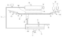
도 1은 본 발명 인라인 방식의 태양전지 제조용 씨비디 장치의 개략적인 구성도를 나타낸 것이다.1 shows a schematic configuration diagram of a CD device for manufacturing an inline solar cell of the present invention.
본 발명은 CIGS계 태양전지의 광흡수층과 투명전도막(TCO 층) 사이에 형성되는 버퍼층을 화학적 용액 성장법을 통해 증착하기 위한 씨비디(CBD:Chemical Bath Deposition) 장치로서, 기판의 상부면에 증착된 광흡수층[구리(Cu), 인듐(In), 구리갈륨(Cu/Ga) 및 셀레나이드 화합물 증착층]의 상부에 버퍼층을 적층 형성하기 위한 것이다.The present invention is a CBD (Chemical Bath Deposition) device for depositing a buffer layer formed between a light absorption layer and a transparent conductive film (TCO layer) of a CIGS-based solar cell by a chemical solution growth method, the upper surface of the substrate A buffer layer is laminated on the deposited light absorbing layer (copper (Cu), indium (In), copper gallium (Cu / Ga) and selenide compound deposition layer).
본 발명은 도시된 바와 같이, 반송수단(110,120), 약액저장조(10), 샤워헤드(30), 및 기판로딩부(40)로 구성된다As shown, the present invention comprises a conveying means (110, 120),
반송수단(110,120)은 기판(100)을 이송시키기 위한 것으로서, 다수개의 이송롤러나 컨베이어벨트로 구성될 수 있으며, 하기에서 설명하는 기판로딩부(40)에 기판(100)을 용이하게 로딩 또는 언로딩시킬 수 있도록 기판로딩부(40)의 양측부에 인접되게 각각 설치된다.The conveying means (110, 120) is for transporting the
한편 약액저장조(10)는 기판(100)상에 버퍼층을 형성하기 위한 약액(Cds 용액)(200)이 저장되는 부분으로서, 기판로딩부(40)의 하측부에 설치될 수 있을 것이다.Meanwhile, the
약액저장조(10)는 샤워헤드(30)로 공급되는 약액(200)이 저장되는 부분으로서, 내부가 비어 있는 통상적인 밀폐식 용기형태로 구비될 수 있으며, 일측에는 약 액공급관(12)이 설치되고 타측에는 약액공급부(60)가 설치된다. The chemical
이때 약액공급관(12)은 약액(200)이 샤워헤드(30)로 공급될 수 있도록 샤워헤드(30)와 연결되며, 약액(200)의 투입을 조절할 수 있는 밸브(도시하지 않음)가 설치될 수 있을 것이다.In this case, the chemical
또한 약액저장조(10)에는 약액(200)을 약액공급관(12)을 통해 샤워헤드(30)로 송출하는 펌프(도시하지 않음)가 설치될 수 있으며, 또한 약액(200)의 PH를 측정할 수 있는 PH측정기(15)가 설치되는 것이 바람직하다.In addition, the
한편 약액저장조(10)의 하측부에는 반응이 완료된 약액(200)이나 또는 하기에서 설명하는 세정액을 외부로 배출시킬 수 있는 배출구(17)가 구비된다.On the other hand, the lower side of the
약액(200)은 Cds4와 Cs(NH3)2 및 NH4OH 의 혼합용액이 사용될 수 있으며, 약액(200)의 기체 성분은 약액공급관(12)에 별도의 기체공급부(65)를 설치하여 공급할 수 있을 것이다.The
한편 샤워헤드(30)는 기판로딩부(40) 상부에 위치하여 기판(100)상에 약액(200)을 공급하는 것으로서, 중심축을 기준으로 회전 가능하게 설치된다.Meanwhile, the
이하 샤워헤드(30,30')의 일 실시예를 도 2와 도 3을 참조하여 설명한다.Hereinafter, an embodiment of the
도 2와 도 3은 샤워헤드(30,30')의 일 실시예를 각각 나타낸 사시도이다.2 and 3 are perspective views showing one embodiment of the
도 2에 도시된 바와 같이, 샤워헤드(30)는 내부가 비어 있는 일정 길이의 회전식 원통 롤러 형태로 형성되는 것으로서, 양단부에는 중심축 역할을 하는 회전축(32)이 각각 돌출 형성된다.As shown in FIG. 2, the
또한 샤워헤드(30)의 외주면에는 내부에 투입된 약액(200)을 배출하는 슬릿(35)이 길이 방향을 따라 관통 형성된다.In addition, the outer circumferential surface of the
한편 약액공급관(12)은 샤워헤드(30)의 일단부에 돌출 형성된 회전축(32)과 연결될 수 있으며, 이때 회전축(32)에는 약액공급관(12)의 단부가 삽입 설치됨과 동시에 샤워헤드(30)의 내부와 연통되도록 연결공(33)이 관통 형성된다.Meanwhile, the chemical
이때 회전축(32)은 약액공급관(12)의 단부에 외삽되어 회전 가능하게 설치되는 것이다.At this time, the rotating
한편 연결공(33)의 내측에는 샤워헤드(30)의 원활한 회전이 가능하도록 베어링이 구비될 수 있으며, 또한 약액(200)의 외부 누출이 차단될 수 있도록 오링(O-ring) 등과 같은 실링부재가 설치되는 것이 바람직하다.On the other hand, a bearing may be provided inside the
샤워헤드(30)는 회전축(32)을 별도의 지지프레임(도시하지 않음)에 회전 가능하게 결합하고, 회전축(32)을 구동모터와 연결되는 기어 또는 벨트 등과 같은 통상적인 회전력 전달수단(도시하지 않음)에 연결함으로써, 회전되도록 설치될 수 있을 것이다.The
이때 샤워헤드(30)의 일측부에는 샤워헤드(30)를 일정 진폭으로 진동시킬 수 있은 진동장치(바이브레이터,vibrator) 등을 설치함으로써, 내부의 약액(200)이 균일하게 교반되도록 할 수 있을 것이다.In this case, by installing a vibrator (vibrator) or the like capable of vibrating the
따라서 약액(200)은 약액저장조(10)로부터 약액공급관(12)을 통해 샤워헤드(30)로 투입된 후, 샤워헤드(30)의 진동에 의해 교반되고, 이 후 샤워헤드(30)가 회전되어 슬릿(35)이 하측부에 외치하게 되면, 슬릿(35)을 통해 기판로딩부(40)에 로딩된 기판(100) 상부에 배출되는 것이다.Therefore, the
한편 도 3은 다른 형태의 샤워헤드(30')를 도시한 것으로서, 도시된 바와 같이, 샤워헤드(30')는 내부가 비어 있고 상부가 개방된 일정 깊이의 사각 형상의 용기 형태로 형성된다.Meanwhile, FIG. 3 illustrates another type of shower head 30 '. As shown, the shower head 30' is formed in the shape of a rectangular container having a predetermined depth with an empty inside and an open top.
이때 샤워헤드(30')는 도 2의 실시예의 샤워헤드(30)와 마찬가지로 양측면에는 회전축(32')이 돌출 형성되고, 일측의 회전축(32')에는 약액공급관(12)의 단부에 외삽되어 회전 가능하게 결합되는 연결공(33')이 관통 형성되며, 샤워헤드(30')를 일정 진폭으로 진동시킬 수 있도록 진동장치(바이브레이터,vibrator)가 설치된다.At this time, the shower head 30 'is similar to the
즉, 샤워헤드(30')는 약액공급관(12)을 통해 내부에 투입된 약액(200)이 균일하게 교반되도록 함과 동시에 회전 가능하게 설치됨으로써, 요동 가능한 회전식 용기 형태로 구비되는 것이다.That is, the
따라서 약액(200)은 약액저장조(10)로부터 약액공급관(12)을 통해 샤워헤드(30')로 투입된 후, 샤워헤드(30')의 진동에 의해 교반되고, 이 후 샤워헤드(30')가 회전되어 상부가 하측을 향하게 되면, 기판로딩부(40)에 로딩된 기판(100) 상부에 쏟아져 배출되는 것이다.Therefore, the
한편 샤워헤드(30,30')에는 세정을 위해 세정액을 공급할 수 있는 세정액공급장치(도시하지 않음)가 별도로 연결 설치될 수 있다.The shower heads 30 and 30 'may be separately connected to a cleaning solution supply device (not shown) capable of supplying the cleaning solution for cleaning.
이하 기판로딩부(40)를 도 4를 참조하여 상세히 설명한다.Hereinafter, the
도 4는 기판로딩부(40)의 측면도를 나타낸 것이다.4 shows a side view of the
기판로딩부(40)는 기판(100)이 안착되는 부분으로서, 기판(100)의 저면을 지지할 수 있도록 일정 두께로 형성되며, 둘레에는 샤워헤드(30)로부터 배출된 약액(200)이 일정 높이만큼 수용될 수 있도록 외측 방향으로 상향 경사지게 형성되는 경사면(45)이 구비된다.The
따라서 샤워헤드(30)는 기판(100)이 완전히 잠길 정도의 높이만큼 약액(200)을 기판로딩부(40)에 배출하게 되는 것이다.Accordingly, the
한편 기판로딩부(40)의 저면 일측부에는 기판(100)과 반응이 완료된 약액(200)을 외부로 자연 배출시키는 배출관(50)이 설치된다.On the other hand, one side of the bottom surface of the
이때 배출관(50)은 약액저장조(10)로 연결되도록 함으로써, 필요시 약액(200)을 회수하여 샤워헤드(30)로 재순환되도록 함으로써, 약액(200)을 재활용할 수도 있을 것이다.In this case, the
기판로딩부(40)의 양측부에 각각 인접되게 설치되는 반송수단(110,120)은 기판(100)의 로딩과 언로딩이 용이하도록 기판로딩부(40)의 경사면(45)과 동일한 경사로 설치되는 것이 바람직하다.The conveying means 110 and 120 installed adjacent to both side portions of the
또한 기판로딩부(40)에는 기판(100)을 일정 온도로 가열시키기 위한 가열수단이 구비된다.In addition, the
가열수단은 증착 반응이 약 40℃ ~ 80℃에서 진행하게 되므로 기판로딩부(40)를 가열하여 상부에 안착된 기판(100)이 공정 진행 동안 상기 온도로 유지되도록 하는 것이다.The heating means is a deposition reaction proceeds at about 40 ℃ ~ 80 ℃ to heat the
이때 가열수단은 통상적인 히팅라인을 설치하여 구성할 수 있을 것이다.At this time, the heating means may be configured by installing a conventional heating line.
또한 기판로딩부(40)에는 양측부가 반송수단(110,120)과 각각 연결될 수 있는 컨베이어벨트(도시하지 않음)를 설치함으로써, 기판(100)의 로딩과 언로딩이 연속적으로 이루어지도록 할 수 있을 것이다.In addition, by installing a conveyor belt (not shown), both sides of which are connected to the conveying means 110 and 120, respectively, the
한편 증착이 완료된 기판(100)을 이송하는 반송수단(120)의 상측부에는 후처리수단(70)이 설치될 수 있다.On the other hand, the post-processing means 70 may be installed on the upper portion of the transfer means 120 for transporting the
후처리수단(70)은 버퍼층의 증착이 완료된 기판(100)을 세정 및 건조시키기 위한 것으로서, 세정노즐(71)과 에어건(75)으로 구성될 수 있다.The post-treatment means 70 is for cleaning and drying the
세정노즐(71)과 에어건(75)은 기판(100)의 이송 방향을 따라 반송수단(120)의 상측부에 순차적으로 설치됨으로써, 이송되는 기판(100)상에 세정액과 건조용 에어를 순차적으로 분사하게 되는 것이다.The cleaning
이때 반송수단(120)은 세정액이 기판로딩부(40)로 흘러내릴 수 있도록 기판로딩부(40)의 경사면(45) 상단부와 연결되도록 배수로(도시하지 않음)를 설치함으로써, 세정액이 반송수단(120)의 배수로를 통해 기판로딩부(40)로 흘러내린 후 배출관(50)을 통해 배출되도록 할 수 있다.At this time, the conveying means 120 is provided with a drainage path (not shown) so as to be connected to the upper end of the
이하 도 5를 참조하여 본 발명의 작동과정을 상세히 설명한다.Hereinafter, the operation of the present invention will be described in detail with reference to FIG. 5.
도 5는 본 발명의 작동과정을 나타낸 플로우차트이다.5 is a flowchart showing the operation of the present invention.
먼저 반송수단(110)에 의해 기판(100)이 기판로딩부(40)에 안착되어 기판 로딩(S10)이 완료되면, 약액저장조(10)로부터 샤워헤드(30)로 약액 공급(S20)이 이루어진다.First, when the
샤워헤드(30)에 약액(200)이 투입되면, 약액(200)은 샤워헤드(30)의 진동에 의해 균일하게 교반됨과 동시에 샤워헤드 회전(S30)에 의해 슬릿(35)을 통해 기판로딩부(40)로 배출됨으로써, 약액 배출(S40) 과정이 진행된다.When the
이때 약액공급관(12)과 샤워헤드(30)는 3℃ ~ 5℃가 유지되도록 하는 것이 바람직하다.At this time, the chemical
또한 기체공급부(65)는 반응에 필요한 기체 성분을 샤워헤드(30)를 통해 기판로딩부(40)에 공급할 수 있을 것이다.In addition, the
한편 약액 배출(S40)이 완료되면 기판(100)은 약액(200)과 반응하여 표면에 버퍼층 증착(S50)이 이루어지게 되는 것이다.Meanwhile, when the chemical liquid discharge (S40) is completed, the
버퍼층 증착(S50)이 완료되면 반송수단(120)에 의해 기판 언로딩(S60)이 진행된다.When the buffer layer deposition S50 is completed, the substrate unloading S60 is performed by the transfer means 120.
이때 기판로딩부(40)에 수용된 약액(200)은 배출관(50)을 통해 약액저장조(10)로 이동한 후, 약액저장조(10)의 배출구(17)를 통해 외부로 배출되거나 또는 샤워헤드(30)로 재순환되어 재활용될 수 있을 것이다.At this time, the
한편 샤워헤드(30)에 별도로 연결되는 세정액 공급수단은 샤워헤드(30)에 세정액을 공급하여 세정액이 배출공(35)을 통해 배출되게 함으로써, 샤워헤드(30)의 세정과 기판로딩부 세정(S70)이 순차적으로 수행되도록 할 수 있으며, 이 후 세정액은 약액저장조(10)로 이동한 후 배출구(17)를 통해 외부로 배출되는 것이다.Meanwhile, the cleaning solution supply means connected to the
이때 반송수단(120)에 의해 이송되는 기판(100)은 후처리수단(70)의 세정노즐(71)과 에어건(75)에 의해 기판 세정 및 건조(S80)가 순차적으로 이루어지게 되며, 세정액은 기판로딩부(40)로 흘러내려 배출관(50)과 약액저장조(10)의 배출 구(17)를 통해 외부로 배출되는 것이다 .In this case, the
상기와 같은 세정이 완료되면 약액공급부(60)는 약액저장조(10)에 적정량의 약액(200)을 다시 투입하게 되고, 약액(200)은 다시 약액공급관(12)과 샤워헤드(30)를 경유하여 기판로딩부(40)로 순환하게 되는 것이다.When the cleaning is completed as described above, the chemical
이때 기판로딩부 세정(S70)과 기판 세정 및 건조(S80)는 동시에 수행될 수 있을 것이다.At this time, the substrate loading unit cleaning (S70) and the substrate cleaning and drying (S80) may be performed at the same time.
한편 약액(200)을 재활용하고자 하는 경우에는 기판 세정 및 건조(S80)시 발생하는 세정액이 기판로딩부(40)로 흘러내리지 않고 반송수단(120)에서 바로 외부로 배출되도록 하고, 약액(200)을 약액저장조(10)와 샤워헤드(30) 및 기판로딩부(40)로 재순환시키면 되는 것이다.On the other hand, when the
따라서 본 발명은 약액(200) 공급에 있어서 인라인 형태의 샤워헤드 방식을 채택함으로써, 적정량의 약액(200) 공급은 물론 간단한 회전 방식 또는 요동방식의 교반 수단을 통해 설비 비용을 현저히 절감할 수 있게 되며, 또한 샤워헤드(30,30') 자체의 교반 작용을 통해 샤워헤드(30'30')의 세정이 용이할 뿐 아니라, 약액(200)의 막힘 현상이나 응고 현상이 방지되어 공정 불량이 감소될 수 있게 되고, 또한 증착 공정과 세정 공정이 연속적으로 수행 가능하여 약액(200)의 외부 누출 방지는 물론 공정 효율을 현저히 향상시킬 수 있게 되는 것이다.Therefore, the present invention adopts an inline type showerhead method in supplying the
이상, 상기의 실시 예는 단지 설명의 편의를 위해 예시로서 설명한 것에 불과하므로 특허청구범위를 한정하는 것은 아니다.As described above, the above embodiments are merely described as examples for convenience of description and are not intended to limit the scope of the claims.
도 1은 본 발명의 인라인 방식의 태양전지 제조용 씨비디 장치의 개략적인 구성도,1 is a schematic configuration diagram of a CD device for manufacturing an inline solar cell of the present invention;
도 2는 본 발명의 샤워헤드의 일 실시예의 사시도,2 is a perspective view of one embodiment of a showerhead of the present invention;
도 3은 본 발명의 샤워헤드의 다른 실시예의 사시도,3 is a perspective view of another embodiment of the showerhead of the present invention;
도 4는 본 발명의 인라인 방식의 태양전지 제조용 씨비디 장치의 작동과정을 나타낸 플로우차트이다.Figure 4 is a flow chart showing the operation of the CD device for manufacturing an inline solar cell of the present invention.
* 도면의 주요 부분에 대한 부호의 설명 *Explanation of symbols on the main parts of the drawings
10 : 약액저장조 12 : 약액공급관10: chemical liquid storage tank 12: chemical liquid supply pipe
15 : PH측정기 17 : 배출구15
30,30' : 샤워헤드 32,32' : 회전축30,30 ':
33,33' : 연결공 35 : 슬릿33,33 ': Connector 35: Slit
40 : 기판로딩부 45 : 경사면40: substrate loading portion 45: inclined surface
50 : 배출관 60 : 약액공급부50: discharge pipe 60: chemical supply unit
65 : 기체공급부 70 : 후처리수단65
71 : 세정노즐 75 : 에어건71: cleaning nozzle 75: air gun
100 : 기판 110,120 : 반송수단100:
200 : 용액 300 : 챔버200: solution 300: chamber
S10 : 기판 로딩 S20 : 약액 공급S10: substrate loading S20: chemical supply
S30 : 샤워헤드 회전 S40 : 약액 배출S30: rotation of the shower head S40: chemical liquid discharge
S50 : 버퍼층 증착 S60 : 기판 언로딩S50: buffer layer deposition S60: substrate unloading
S70 : 기판로딩부 세정 S80 : 기판 세정/건조S70: Clean the substrate loading part S80: Clean the substrate / dry
Claims (7)
Priority Applications (1)
| Application Number | Priority Date | Filing Date | Title |
|---|---|---|---|
| KR1020090119709A KR101092067B1 (en) | 2009-12-04 | 2009-12-04 | Chemical Bath Deposition apparatus of in-line type for manufacturing solar cell |
Applications Claiming Priority (1)
| Application Number | Priority Date | Filing Date | Title |
|---|---|---|---|
| KR1020090119709A KR101092067B1 (en) | 2009-12-04 | 2009-12-04 | Chemical Bath Deposition apparatus of in-line type for manufacturing solar cell |
Publications (2)
| Publication Number | Publication Date |
|---|---|
| KR20110062858A KR20110062858A (en) | 2011-06-10 |
| KR101092067B1 true KR101092067B1 (en) | 2011-12-12 |
Family
ID=44396969
Family Applications (1)
| Application Number | Title | Priority Date | Filing Date |
|---|---|---|---|
| KR1020090119709A Expired - Fee Related KR101092067B1 (en) | 2009-12-04 | 2009-12-04 | Chemical Bath Deposition apparatus of in-line type for manufacturing solar cell |
Country Status (1)
| Country | Link |
|---|---|
| KR (1) | KR101092067B1 (en) |
Cited By (1)
| Publication number | Priority date | Publication date | Assignee | Title |
|---|---|---|---|---|
| WO2025083670A1 (en) * | 2023-10-18 | 2025-04-24 | 한화솔루션 주식회사 | Method and apparatus for manufacturing solar cells |
Families Citing this family (2)
| Publication number | Priority date | Publication date | Assignee | Title |
|---|---|---|---|---|
| DE102011077526A1 (en) * | 2011-06-15 | 2012-12-20 | Robert Bosch Gmbh | Method for producing a semiconductor device |
| US8726835B2 (en) * | 2011-06-30 | 2014-05-20 | Jiaxiong Wang | Chemical bath deposition apparatus for fabrication of semiconductor films |
Citations (2)
| Publication number | Priority date | Publication date | Assignee | Title |
|---|---|---|---|---|
| JP2007141926A (en) * | 2005-11-15 | 2007-06-07 | Sony Corp | Substrate processing apparatus and substrate processing method |
| KR100820362B1 (en) * | 2006-11-17 | 2008-04-08 | 주식회사 디엠에스 | Chemical feeder |
-
2009
- 2009-12-04 KR KR1020090119709A patent/KR101092067B1/en not_active Expired - Fee Related
Patent Citations (2)
| Publication number | Priority date | Publication date | Assignee | Title |
|---|---|---|---|---|
| JP2007141926A (en) * | 2005-11-15 | 2007-06-07 | Sony Corp | Substrate processing apparatus and substrate processing method |
| KR100820362B1 (en) * | 2006-11-17 | 2008-04-08 | 주식회사 디엠에스 | Chemical feeder |
Cited By (1)
| Publication number | Priority date | Publication date | Assignee | Title |
|---|---|---|---|---|
| WO2025083670A1 (en) * | 2023-10-18 | 2025-04-24 | 한화솔루션 주식회사 | Method and apparatus for manufacturing solar cells |
Also Published As
| Publication number | Publication date |
|---|---|
| KR20110062858A (en) | 2011-06-10 |
Similar Documents
| Publication | Publication Date | Title |
|---|---|---|
| JP3837026B2 (en) | Substrate cleaning apparatus and substrate cleaning method | |
| CN101866981B (en) | Thin film deposition process module for manufacturing solar cell, thin film deposition process system for manufacturing solar cell, and cleaning method for thin film deposition process module | |
| WO2001048800A1 (en) | Semiconductor wafer processing apparatus and processing method | |
| EP1054457A2 (en) | Method and apparatus for manufacturing a semiconductor device | |
| US9362440B2 (en) | 60×120 cm2 prototype electrodeposition cell for processing of thin film solar panels | |
| KR101092067B1 (en) | Chemical Bath Deposition apparatus of in-line type for manufacturing solar cell | |
| KR20110119098A (en) | Inline Substrate Processing Equipment | |
| JP5006245B2 (en) | Method and apparatus for manufacturing chalcopyrite thin film solar cell | |
| US8138009B2 (en) | Method of fabricating thin film solar cell and apparatus for fabricating thin film solar cell | |
| JP2020533789A (en) | Semiconductor wafer cleaning method and cleaning equipment | |
| TWI468543B (en) | Substrate transfer and processing system and substrate transfer and processing methods | |
| CN106169521A (en) | What a kind of crystal silicon solar energy battery was processed removes phosphorosilicate glass machining production line | |
| TWI460305B (en) | Apparatus for chemical bath deposition | |
| KR101035245B1 (en) | CD device for manufacturing solar cell | |
| KR101220094B1 (en) | System for cleaning wafer carrier | |
| US6348159B1 (en) | Method and apparatus for etching coated substrates | |
| KR20100088139A (en) | Method and apparatus for coating carrier for thin film solar cell | |
| JP5593233B2 (en) | Single-sided high-throughput wet etching and wet processing apparatus and method | |
| CN103184439A (en) | Chemical bath deposition apparatus and method for manufacturing thin film solar cells | |
| CN103008168A (en) | Device and method for depositing film | |
| CN210575853U (en) | High-efficient crystal silicon heterojunction solar cell silicon chip belt cleaning device | |
| KR101142417B1 (en) | Buffer layer deposition apparatus for thin-film solar cells and method for deposition of buffer layer using the same | |
| KR101097712B1 (en) | Deposition apparatus using chemical solution growth method | |
| CN112670377A (en) | Heterojunction solar cell processing technology | |
| EP3083461B1 (en) | Web based chemical bath deposition apparatus |
Legal Events
| Date | Code | Title | Description |
|---|---|---|---|
| A201 | Request for examination | ||
| PA0109 | Patent application |
St.27 status event code: A-0-1-A10-A12-nap-PA0109 |
|
| PA0201 | Request for examination |
St.27 status event code: A-1-2-D10-D11-exm-PA0201 |
|
| D13-X000 | Search requested |
St.27 status event code: A-1-2-D10-D13-srh-X000 |
|
| D14-X000 | Search report completed |
St.27 status event code: A-1-2-D10-D14-srh-X000 |
|
| E902 | Notification of reason for refusal | ||
| PE0902 | Notice of grounds for rejection |
St.27 status event code: A-1-2-D10-D21-exm-PE0902 |
|
| E13-X000 | Pre-grant limitation requested |
St.27 status event code: A-2-3-E10-E13-lim-X000 |
|
| P11-X000 | Amendment of application requested |
St.27 status event code: A-2-2-P10-P11-nap-X000 |
|
| P13-X000 | Application amended |
St.27 status event code: A-2-2-P10-P13-nap-X000 |
|
| PG1501 | Laying open of application |
St.27 status event code: A-1-1-Q10-Q12-nap-PG1501 |
|
| E701 | Decision to grant or registration of patent right | ||
| PE0701 | Decision of registration |
St.27 status event code: A-1-2-D10-D22-exm-PE0701 |
|
| GRNT | Written decision to grant | ||
| PR0701 | Registration of establishment |
St.27 status event code: A-2-4-F10-F11-exm-PR0701 |
|
| PR1002 | Payment of registration fee |
St.27 status event code: A-2-2-U10-U11-oth-PR1002 Fee payment year number: 1 |
|
| PG1601 | Publication of registration |
St.27 status event code: A-4-4-Q10-Q13-nap-PG1601 |
|
| P22-X000 | Classification modified |
St.27 status event code: A-4-4-P10-P22-nap-X000 |
|
| FPAY | Annual fee payment |
Payment date: 20141001 Year of fee payment: 4 |
|
| PR1001 | Payment of annual fee |
St.27 status event code: A-4-4-U10-U11-oth-PR1001 Fee payment year number: 4 |
|
| PN2301 | Change of applicant |
St.27 status event code: A-5-5-R10-R13-asn-PN2301 St.27 status event code: A-5-5-R10-R11-asn-PN2301 |
|
| R18-X000 | Changes to party contact information recorded |
St.27 status event code: A-5-5-R10-R18-oth-X000 |
|
| FPAY | Annual fee payment |
Payment date: 20151126 Year of fee payment: 5 |
|
| PR1001 | Payment of annual fee |
St.27 status event code: A-4-4-U10-U11-oth-PR1001 Fee payment year number: 5 |
|
| FPAY | Annual fee payment |
Payment date: 20161201 Year of fee payment: 6 |
|
| PR1001 | Payment of annual fee |
St.27 status event code: A-4-4-U10-U11-oth-PR1001 Fee payment year number: 6 |
|
| R18-X000 | Changes to party contact information recorded |
St.27 status event code: A-5-5-R10-R18-oth-X000 |
|
| FPAY | Annual fee payment |
Payment date: 20171027 Year of fee payment: 7 |
|
| PR1001 | Payment of annual fee |
St.27 status event code: A-4-4-U10-U11-oth-PR1001 Fee payment year number: 7 |
|
| LAPS | Lapse due to unpaid annual fee | ||
| PC1903 | Unpaid annual fee |
St.27 status event code: A-4-4-U10-U13-oth-PC1903 Not in force date: 20181203 Payment event data comment text: Termination Category : DEFAULT_OF_REGISTRATION_FEE |
|
| PC1903 | Unpaid annual fee |
St.27 status event code: N-4-6-H10-H13-oth-PC1903 Ip right cessation event data comment text: Termination Category : DEFAULT_OF_REGISTRATION_FEE Not in force date: 20181203 |
|
| P22-X000 | Classification modified |
St.27 status event code: A-4-4-P10-P22-nap-X000 |