KR100833362B1 - How to control the vacuum cleaner - Google Patents
How to control the vacuum cleaner Download PDFInfo
- Publication number
- KR100833362B1 KR100833362B1 KR1020060098191A KR20060098191A KR100833362B1 KR 100833362 B1 KR100833362 B1 KR 100833362B1 KR 1020060098191 A KR1020060098191 A KR 1020060098191A KR 20060098191 A KR20060098191 A KR 20060098191A KR 100833362 B1 KR100833362 B1 KR 100833362B1
- Authority
- KR
- South Korea
- Prior art keywords
- dust collecting
- foreign matter
- pressing plate
- foreign material
- pressure plate
- Prior art date
- Legal status (The legal status is an assumption and is not a legal conclusion. Google has not performed a legal analysis and makes no representation as to the accuracy of the status listed.)
- Expired - Fee Related
Links
Images


Classifications
-
- A—HUMAN NECESSITIES
- A47—FURNITURE; DOMESTIC ARTICLES OR APPLIANCES; COFFEE MILLS; SPICE MILLS; SUCTION CLEANERS IN GENERAL
- A47L—DOMESTIC WASHING OR CLEANING; SUCTION CLEANERS IN GENERAL
- A47L9/00—Details or accessories of suction cleaners, e.g. mechanical means for controlling the suction or for effecting pulsating action; Storing devices specially adapted to suction cleaners or parts thereof; Carrying-vehicles specially adapted for suction cleaners
- A47L9/10—Filters; Dust separators; Dust removal; Automatic exchange of filters
- A47L9/19—Means for monitoring filtering operation
-
- A—HUMAN NECESSITIES
- A47—FURNITURE; DOMESTIC ARTICLES OR APPLIANCES; COFFEE MILLS; SPICE MILLS; SUCTION CLEANERS IN GENERAL
- A47L—DOMESTIC WASHING OR CLEANING; SUCTION CLEANERS IN GENERAL
- A47L9/00—Details or accessories of suction cleaners, e.g. mechanical means for controlling the suction or for effecting pulsating action; Storing devices specially adapted to suction cleaners or parts thereof; Carrying-vehicles specially adapted for suction cleaners
- A47L9/10—Filters; Dust separators; Dust removal; Automatic exchange of filters
- A47L9/106—Dust removal
- A47L9/108—Dust compression means
-
- A—HUMAN NECESSITIES
- A47—FURNITURE; DOMESTIC ARTICLES OR APPLIANCES; COFFEE MILLS; SPICE MILLS; SUCTION CLEANERS IN GENERAL
- A47L—DOMESTIC WASHING OR CLEANING; SUCTION CLEANERS IN GENERAL
- A47L9/00—Details or accessories of suction cleaners, e.g. mechanical means for controlling the suction or for effecting pulsating action; Storing devices specially adapted to suction cleaners or parts thereof; Carrying-vehicles specially adapted for suction cleaners
- A47L9/28—Installation of the electric equipment, e.g. adaptation or attachment to the suction cleaner; Controlling suction cleaners by electric means
- A47L9/2805—Parameters or conditions being sensed
- A47L9/2831—Motor parameters, e.g. motor load or speed
Landscapes
- Engineering & Computer Science (AREA)
- Mechanical Engineering (AREA)
- Filters For Electric Vacuum Cleaners (AREA)
Abstract
본 발명은 집진 유닛의 집진 용량이 증가되도록 하며, 집진 유닛에 일정량 이상의 이물이 집진된 경우 이물의 비움 시기가 표시되도록 하는 진공 청소기의 제어 방법에 관한 것이다. The present invention relates to a control method of the vacuum cleaner to increase the dust collecting capacity of the dust collecting unit, and to display the emptying time of the foreign matter when a certain amount of foreign matter is collected in the dust collecting unit.
본 발명은 집진 용기내에서 좌우 회전 이동하는 제 1 가압판과 집진 용기내에 고정되어 상기 집진 용기 공간을 양분하는 제 2 가압판을 이용하여 상기 집진 용기내의 이물을 압착시키는 진공청소기의 제어 방법으로, 상기 제 2 가압판에 대하여 180도 회전한 위치(기준 위치)에 상기 제 1 가압판이 위치하는 것을 확인하는 제 1 단계; 상기 제 1 가압판이 상기 기준 위치로부터 상기 제 2 가압판을 향하여 시계 방향 또는 반시계 방향으로 회전 이동한 후 다시 반시계 방향 또는 시계 방향으로 역회전 이동하여 상기 기준 위치로 복귀하기까지의 왕복시간을 측정하여 상기 집진 기내에 쌓인 이물의 양을 판단하는 제 2 단계로 이루어진다.The present invention relates to a control method of a vacuum cleaner for compressing foreign substances in the dust collecting container by using a first pressure plate which is rotated in a dust collecting container and a second pressure plate which is fixed in the dust collecting container and bisects the dust collecting container space. A first step of confirming that the first pressing plate is positioned at a position (reference position) rotated 180 degrees with respect to the pressing plate; Measuring the reciprocating time until the first pressure plate is rotated clockwise or counterclockwise from the reference position toward the second pressure plate and then rotated counterclockwise or clockwise to return to the reference position. The second step is to determine the amount of foreign matter accumulated in the dust collector.
상기와 같은 본 발명에 의하면, 상기 집진 유닛 내부에 소정량 이상의 이물이 집진되면, 상기 집진 유닛의 이물 비움 시기가 표시되어 사용자가 이물을 비우는 시기를 쉽게 알 수 있는 효과가 있다. According to the present invention as described above, when the foreign matter is collected in a predetermined amount or more inside the dust collecting unit, when the foreign material emptying time of the dust collecting unit is displayed, there is an effect that the user can easily know when to empty the foreign material.
공기청정기, 집진 유닛, 가압판, 압축 모터, 이물, 먼지 Air Purifier, Dust Collector, Pressure Plate, Compression Motor, Foreign Material, Dust
Description
도 1은 본 발명의 사상에 따른 진공 청소기에서 집진 유닛이 분리된 상태의 사시도.1 is a perspective view of a dust collecting unit is separated from the vacuum cleaner according to the spirit of the present invention.
도 2는 상기 진공 청소기에 적용되는 집진 유닛 장착부와 집진 유닛을 분리하여 나타낸 사시도.Figure 2 is a perspective view showing the dust collecting unit mounting portion and the dust collecting unit applied to the vacuum cleaner separately.
도 3은 상기 집진 유닛의 단면 사시도.3 is a sectional perspective view of the dust collecting unit.
도 4는 도 3의 A부분의 확대도. 4 is an enlarged view of a portion A of FIG. 3.
도 5는 상기 집진 유닛에 저장된 이물의 압축을 위하여 제공되는 구동 장치와 집진 유닛의 결합 관계를 보여주는 사시도.FIG. 5 is a perspective view illustrating a coupling relationship between a drive unit and a dust collecting unit provided for compressing a foreign material stored in the dust collecting unit. FIG.
도 6은 상기 집진 유닛의 이물 분리부와 집진 용기를 분리하여 나타낸 사시도.6 is a perspective view showing the foreign matter separating portion and the dust collecting container of the dust collecting unit separately.
도 7는 도 6에 도시된 이물 분리부의 하부 사시도.7 is a bottom perspective view of the foreign material separation unit shown in FIG. 6.
도 8 및 도 9는 상기 집진 유닛 내부의 이물 압축 과정을 보여주는 집진 용기의 평면도.8 and 9 are plan views of a dust collecting container showing a foreign material compression process inside the dust collecting unit.
도 10는 상기 이물 비움 알림 기능의 수행시 제 1 가압판의 작동 상태를 보여주는 평면도.10 is a plan view showing an operating state of the first pressing plate when performing the foreign material emptying notification function.
도 11은 본 발명에 따른 진공청소기의 제어 장치를 보여주는 블럭도이다.11 is a block diagram showing a control device of the vacuum cleaner according to the present invention.
도 12(a)는 본 발명에서 사용되는 종동기어의 외관사시도이다.12 (a) is an external perspective view of a driven gear used in the present invention.
도 12(b)는 도 12a에 도시된 종동기어의 정면도이다.Fig. 12B is a front view of the driven gear shown in Fig. 12A.
도 12(c)는 마이크로 스위치와 종동기어의 체결 관계를 설명하는 도면이다. Fig. 12C is a diagram for explaining the fastening relationship between the micro switch and the driven gear.
도 13 내지 도 15는 제 1 가압판의 위치에 따른 마이크로 스위치의 온/오프 상태를 설명하는 도면이다. 13 to 15 are diagrams illustrating the on / off state of the micro switch according to the position of the first pressing plate.
도 16은 본 발명에 따른 제 1 가압판의 회전 동작을 개념적으로 설명하는 도면이다. 16 is a diagram conceptually illustrating a rotation operation of the first pressure plate according to the present invention.
도 17은 본 발명에서 제안하는 진공청소기의 제어 방법을 설명하는 흐름도이다. 17 is a flowchart illustrating a control method of the vacuum cleaner proposed in the present invention.
<도면의 주요 부분에 대한 부호의 설명><Explanation of symbols for the main parts of the drawings>
100 : 청소기 본체 200 : 집진 유닛100: cleaner body 200: dust collection unit
310 : 제 1 가압판 320 : 제 2 가압판310: first pressure plate 320: second pressure plate
410 : 종동 기어 420 : 구동 기어410: driven gear 420: drive gear
810: 제어부 820: 동작신호 입력부810: control unit 820: operation signal input unit
830: 먼지교환신호 표시부 840: 흡입모터 드라이버830: dust exchange signal display unit 840: suction motor driver
850: 흡입 모터 860: 압축모터 드라이버850: suction motor 860: compression motor driver
870: 압축 모터 870: compression motor
본 발명은 진공 청소기의 제어 방법에 관한 것으로서, 상세하게는 집진 유닛의 집진 용량이 증가되도록 하며, 집진 유닛에 일정량 이상의 이물이 집진된 경우 이물의 비움 시기가 표시되도록 하는 진공 청소기의 제어 방법에 관한 것이다. The present invention relates to a method of controlling a vacuum cleaner, and more particularly, to a method of controlling a vacuum cleaner to increase the dust collecting capacity of the dust collecting unit and to display the emptying time of the foreign matter when a certain amount of foreign matter is collected in the dust collecting unit. will be.
일반적으로 진공 청소기는 본체 내부에 장착되는 진공 모터에 의하여 발생되는 진공압을 이용하여, 먼지 등의 이물이 포함되어 있는 공기를 흡입한 다음, 본체 내부에서 이물을 필터링하는 장치이다.In general, a vacuum cleaner is a device that sucks air containing foreign matters such as dust and the like by using a vacuum pressure generated by a vacuum motor mounted inside the main body, and then filters the foreign matters inside the main body.
이러한, 진공 청소기는 크게 흡입구인 노즐부가 본체와는 별도로 구비되어 연결관에 의해 연결되는 캐니스터 방식과, 노즐부가 본체와 일체로 형성되는 업라이트 방식으로 구별할 수 있다.Such a vacuum cleaner may be distinguished by a canister method in which a nozzle part, which is a large suction port, is provided separately from the main body and connected by a connecting pipe, and an upright method in which the nozzle part is integrally formed with the main body.
한편, 싸이클론 방식 진공 청소기에 장착되는 집진 유닛은 싸이클론 원리를 이용하여, 흡입된 공기 중에 포함되어 함께 회전하게 되는 이물이 공기로부터 분리 수집되도록 하고, 이물이 제거된 공기는 청소기 외부로 배출되도록 한 장치이다.On the other hand, the dust collecting unit mounted on the cyclone vacuum cleaner uses a cyclone principle, so that foreign matter included in the sucked air and rotated together is separated and collected from the air, and the air from which the foreign matter is removed is discharged to the outside of the cleaner. One device.
상세히, 싸이클론 집진 유닛은 집진 바디와, 상기 집진 바디로 공기가 흡입되도록 하는 흡입구와, 상기 집진 바디로 흡입되는 공기 중에서 이물을 분리시키는 싸이클론부와, 상기 싸이클론부에서 분리된 이물이 저장되는 이물 저장부와, 상기 싸이클론부에서 이물이 분리된 공기가 배출되는 배출구가 포함된다.In detail, the cyclone dust collecting unit includes a dust collecting body, an inlet for allowing air to be sucked into the dust collecting body, a cyclone portion for separating foreign matter from the air sucked into the dust collecting body, and a foreign matter separated from the cyclone portion. The foreign matter storage unit, and the outlet for discharging the air is separated foreign matter from the cyclone unit.
한편, 상기 집진 바디의 하부 공간 즉, 상기 이물 저장부에 저장된 이물은 상기 진공 청소기가 작동하는 동안은 상기 집진 바디 내부의 회전류에 의해서 계속적으로 상기 집진 바디의 내주면을 따라 회전 운동한다. On the other hand, the foreign body stored in the lower space of the dust collecting body, that is, the foreign matter storage unit continuously rotates along the inner circumferential surface of the dust collecting body by the rotational flow inside the dust collecting body while the vacuum cleaner is operating.
그리고, 상기 진공 청소기의 작동이 정지되면, 상기 집진 바디의 저면에 그 대로 가라앉아 밀도가 낮은 상태로 저장된다. When the operation of the vacuum cleaner is stopped, the vacuum cleaner sinks to the bottom of the dust collecting body and is stored in a low density state.
따라서, 종래의 집진 유닛은 상기 진공 청소기가 작동되는 중에 상기 집진 유닛 내부에 소정량 이상의 이물이 집진되면, 이물이 상기 집진 용기의 내벽을 따라 회전하면서 상승하여, 상기 집진 바디의 상부 공간에 형성되는 싸이클론부를 침범하게 되고, 이에 따라 미분리된 먼지가 배출기류에 편승하여 상기 배출구로 배출되므로, 집진 성능이 저하되는 문제점이 있었다. Therefore, in the conventional dust collecting unit, when a predetermined amount or more of foreign matter is collected inside the dust collecting unit while the vacuum cleaner is in operation, the foreign matter rises while rotating along the inner wall of the dust collecting container, and is formed in the upper space of the dust collecting body. There is a problem in that the cyclone portion is violated, and thus the unseparated dust is discharged to the discharge port by piggybacking on the discharge airflow, so that dust collection performance is reduced.
또한, 상기 진공 청소기의 작동이 정지되면, 이물은 상기 집진 바디의 저면에 밀도가 낮은 상태 그대로 가라앉아 저장된다는 문제점이 있다. 이러한 경우, 상기 집진 바디 내부에 쌓이는 이물이 그 무게에 비하여 너무 큰 부피를 차지하게 되므로, 집진 성능의 유지를 위하여 상기 집진 바디를 자주 비워야 하는 불편함이 있었다. In addition, when the operation of the vacuum cleaner is stopped, there is a problem that the foreign material is stored in the lower density of the dust collecting body as it is stored in a low state. In this case, since the foreign matter accumulated in the dust collecting body occupies a volume too large for its weight, there is an inconvenience of frequently emptying the dust collecting body in order to maintain the dust collecting performance.
따라서, 근래에는 청소기 사용의 편의성을 향상시키기 위하여, 상기 집진 바디에 집진되는 이물의 집진 용량을 최대화시키는 동시에 집진 성능을 향상시키기 위한 노력이 계속되고 있다. Therefore, in recent years, in order to improve the convenience of using a cleaner, efforts have been made to maximize the dust collecting capacity of the foreign matter collected in the dust collecting body and at the same time improve the dust collecting performance.
본 발명은 상기된 바와 같은 문제점을 해결하기 위하여 제안된 것으로서, 집진 유닛의 이물 집진 용량이 증대되도록 하는 진공 청소기의 제어 방법을 제안하는 것을 목적으로 한다.The present invention has been proposed to solve the above problems, and an object of the present invention is to propose a control method of a vacuum cleaner to increase the foreign matter collecting capacity of the dust collecting unit.
또한 본 발명은 집진 유닛 내부에 구비된 이물의 압축이 자동으로 수행되는 진공 청소기의 제어 방법을 제안하는 것을 목적으로 한다. In addition, an object of the present invention is to propose a control method of a vacuum cleaner in which the compression of foreign matter provided in the dust collecting unit is automatically performed.
또한, 본 발명은 집진 유닛에 일정량 이상의 이물이 저장된 경우, 이물의 비움 시기가 표시되도록 하는 진공 청소기의 제어 방법을 제안하는 것을 목적으로 한다. In addition, an object of the present invention is to propose a control method of a vacuum cleaner to display the emptying time of the foreign matter, when a certain amount of foreign matter is stored in the dust collecting unit.
상기된 바와 같은 목적을 달성하기 위한 본 발명에 따른 집진 용기내에서 좌우 회전 이동하는 제 1 가압판과 집진 용기내에 고정되어 상기 집진 용기 공간을 양분하는 제 2 가압판을 이용하여 상기 집진 용기내의 이물을 압착시키는 진공청소기의 제어 방법은, 상기 제 2 가압판에 대하여 180도 회전한 위치(기준 위치)에 상기 제 1 가압판이 위치하는 것을 확인하는 제 1 단계; 상기 제 1 가압판이 상기 기준 위치로부터 상기 제 2 가압판을 향하여 시계 방향 또는 반시계 방향으로 회전 이동한 후 다시 반시계 방향 또는 시계 방향으로 역회전 이동하여 상기 기준 위치로 복귀하기까지의 왕복시간을 측정하여 상기 집진 기내에 쌓인 이물의 양을 판단하는 제 2 단계로 이루어지는 것을 특징으로 한다.In order to achieve the object as described above, the foreign material in the dust collecting container is compressed using a first pressure plate which is rotated left and right in the dust collecting container according to the present invention and a second pressure plate fixed in the dust collecting container to divide the dust collecting container space. The method of controlling the vacuum cleaner may include: a first step of confirming that the first pressing plate is positioned at a position (reference position) rotated 180 degrees with respect to the second pressing plate; Measuring the reciprocating time until the first pressure plate is rotated clockwise or counterclockwise from the reference position toward the second pressure plate and then rotated counterclockwise or clockwise to return to the reference position. The second step of determining the amount of foreign matter accumulated in the dust collector.
또한 본 발명은 상기 왕복시간이 소정의 기준 시간에 도달하였는지 여부를 판단하는 제 3 단계; 상기 왕복시간이 상기 소정의 기준 시간에 도달한 경우에는 집진 용기내의 이물을 비우라는 신호를 표시하고, 그렇지 않은 경우에는 상기 제 2 및 제 3 단계를 반복 수행하는 제 4 단계를 더 구비하는 것을 특징으로 한다.The present invention also includes a third step of determining whether the round trip time has reached a predetermined reference time; And a fourth step of displaying a signal to empty the foreign material in the dust collecting container when the round trip time reaches the predetermined reference time, and otherwise repeating the second and third steps. It is done.
또한, 본 발명은, 상기 제 1 단계의 수행 전에 상기 이물의 진공흡입을 가능하게 하는 흡입 모터를 동작시키는 단계; 상기 제 1 가압판의 좌우 회전 이동을 가능하게 하는 압축 모터를 동작시키는 단계를 더 구비하는 것을 특징으로 한다. 이 경우, 본 발명은 상기 제 4 단계에서, 상기 왕복시간이 상기 소정의 기준 시간에 도달한 경우, 상기 집진 용기내의 이물을 비우라는 신호를 표시하기 전에 상기 흡입 모터의 동작을 정지시키는 단계를 더 구비하는 것을 특징으로 한다.In addition, the present invention, the step of operating the suction motor to enable the vacuum suction of the foreign object before the first step; And operating a compression motor that enables left and right rotational movement of the first pressure plate. In this case, the present invention further comprises the step of stopping the operation of the suction motor before displaying the signal to empty the foreign matter in the dust collecting container, when the round trip time reaches the predetermined reference time in the fourth step. It is characterized by including.
제안되는 바와 같은 본 발명에 의하면, 상기 집진 유닛 내부에 소정량 이상의 이물이 집진되면, 상기 집진 유닛의 이물 비움 시기가 표시되어 사용자가 이물을 비우는 시기를 쉽게 알 수 있는 효과가 있다. According to the present invention as proposed, when a foreign matter is collected in a predetermined amount or more inside the dust collecting unit, the foreign material emptying time of the dust collecting unit is displayed, there is an effect that the user can easily know when to empty the foreign material.
이하에서는 도면을 참조하여 본 발명의 구체적인 실시예를 설명한다. 다만, 본 발명의 사상은 제시되는 실시예에 제한되지 아니하며, 본 발명의 사상을 이해하는 당업자는 동일한 사상의 범위 내에서 다른 실시예를 용이하게 제안할 수 있을 것이다. Hereinafter, with reference to the drawings will be described a specific embodiment of the present invention. However, the spirit of the present invention is not limited to the embodiments presented, and those skilled in the art who understand the spirit of the present invention can easily suggest other embodiments within the scope of the same idea.
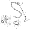
도 1은 본 발명의 사상에 따른 진공 청소기에서 집진 유닛이 분리된 상태의 사시도이고, 도 2는 상기 진공 청소기에 적용되는 집진 유닛 장착부와 집진 유닛을 분리하여 나타낸 사시도이고, 도 3은 상기 집진 유닛의 단면 사시도이며, 도 4는 도 3의 A부분의 확대도이고, 도 5는 상기 집진 유닛에 저장된 이물의 압축을 위하여 제공되는 구동 장치와 집진 유닛의 결합 관계를 보여주는 사시도이다. 1 is a perspective view of the dust collecting unit is separated from the vacuum cleaner according to the spirit of the present invention, Figure 2 is a perspective view showing the dust collecting unit mounting portion and the dust collecting unit is applied to the vacuum cleaner, Figure 3 is the dust collecting unit 4 is an enlarged view of a portion A of FIG. 3, and FIG. 5 is a perspective view illustrating a coupling relationship between a driving device and a dust collecting unit provided for compressing a foreign material stored in the dust collecting unit.
도 1을 참조하면, 본 발명의 사상에 따른 진공 청소기는 내부에 흡입력 발생 수단이 구비되는 청소기 본체(100)와, 흡입된 공기 중에 포함된 이물을 분리하여 저장하는 집진 유닛(200)이 포함되어 구성된다. Referring to FIG. 1, the vacuum cleaner according to the spirit of the present invention includes a cleaner
또한, 상기 진공 청소기는 이물이 포함된 공기를 흡입하는 흡입 노즐(20)과, 사용자가 상기 진공 청소기의 작동을 조작할 수 있도록 하는 핸들(40)과, 상기 흡 입 노즐(20)과 핸들(40)을 연결시키는 연장관과, 상기 흡입 노즐(20)과 상기 청소기 본체(100)를 연결시키는 연결 호스(50)가 더 포함되어 구성된다. In addition, the vacuum cleaner includes a
본 실시예에 있어서 상기 흡입 노즐(20), 연장관(30), 핸들(40) 및 연결 호스(50)의 기본적인 구성은 당업자와 일반 소비자에게 널리 알려져 있으므로 이에 대한 상세한 설명은 생략하기로 한다. In this embodiment, the basic configuration of the
상세히, 상기 청소기 본체(100)의 전면 하단부에는 상기 흡입 노즐로부터 흡입된 이물이 포함된 공기가 흡입되는 본체 흡입부(110)가 형성된다. In detail, a main
그리고, 상기 청소기 본체(100)의 일측면에는 이물이 분리된 공기가 외부로 배출되는 본체 배출부(120)가 형성된다. In addition, one side surface of the
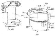
한편, 상기 집진 유닛(200)은 흡입되는 공기 중에 포함된 이물을 분리시키는 이물 분리부(210)와, 상기 이물 분리부에서 분리된 이물이 저장되는 집진 용기(220)가 포함된다. On the other hand, the
여기서, 상기 이물 분리부(210)는 흡입되는 공기에 포함된 이물을 싸이클론 원리 즉 공기와 이물의 원심력 차이로 이물을 분리하는 싸이클론부(211)가 포함된다. 따라서, 상기 싸이클론부(211)에 의해서 분리되는 이물은 상기 집진 용기(220) 내부에 저장된다.Here, the foreign
한편, 상기 집진 유닛(200)은, 그 내부에 저장되는 이물의 집진 용량이 최대화될 수 있도록 구성되는 것이 바람직하다. 이를 위하여, 상기 집진 유닛(200)에는 상기 집진 용기(220) 내부에 저장되는 이물의 부피를 감소시키기 위한 구성이 추가되는 것이 바람직하다. On the other hand, the
이하에서는 도 2 내지 도 5를 참조하여, 이물의 집진 용량이 최대화된 본 발명에 따른 집진 유닛이 구비되는 진공 청소기를 설명한다. Hereinafter, referring to FIGS. 2 to 5, a vacuum cleaner including a dust collecting unit according to the present invention, in which the dust collecting capacity of the foreign material is maximized, will be described.
도 2 내지 도 5를 참조하면, 본 발명의 사상에 따른 집진 유닛(200)은 상기 청소기 본체(100)에 착탈 가능하게 장착된다. 2 to 5, the
그리고, 상기 청소기 본체(100)에는 상기 집진 유닛이 장착되기 위한 집진 유닛 장착부(130)가 제공된다. In addition, the
그리고, 상기 집진 유닛(200)에는 상기 집진 용기(220)에 저장되는 이물의 부피를 감소시켜, 이물의 집진 용량을 증가시키는 한 쌍의 가압판(310, 320)이 구비된다. In addition, the
여기서, 상기 한 쌍의 가압판(310, 320)은, 서로 간의 상호 작용에 의해 이물을 압축하여 이물의 부피를 감소시키며, 이에 따라 상기 집진 용기(220) 내부에 저장되는 이물의 밀도를 감소시킴으로써, 상기 집진 용기(220)의 최대 집진 용량이 증가되도록 한다. Here, the pair of pressure plates (310, 320), by compressing the foreign material by interaction with each other to reduce the volume of the foreign material, thereby reducing the density of the foreign material stored in the
이하에서는 설명의 편의를 위하여, 상기 한 쌍의 가압판(310, 320) 중 어느 하나를 제 1 가압판(310)이라 하고, 다른 하나를 제 2 가압판(320)이라고 한다. Hereinafter, for convenience of description, any one of the pair of
본 실시예에 있어서, 상기 한 쌍의 가압판(310, 320) 중 적어도 어느 하나는 상기 집진 용기(220) 내부에 이동 가능하게 구비되어, 상기 한 쌍의 가압판(310, 320) 사이에서 이물의 압축 작용을 수행한다. In the present embodiment, at least one of the pair of
즉, 상기 제 1 가압판(310)과 제 2 가압판(320)이 상기 집진 용기(220)의 내부에 회전가능하게 구비되는 경우, 상기 제 1 가압판(310)과 제 2 가압판(320) 서 로를 향하여 회전 이동하면서, 상기 제 1 가압판(310)의 일측면과 상기 제 1 가압판(310)의 일측면에 대향되는 상기 제 2 가압판(320)의 일측면 사이의 간격이 좁아지게 되고, 이에 따라 상기 제 1 가압판(310) 및 제 2 가압판(320) 사이에 위치하는 이물이 압축된다. That is, when the first
다만, 본 실시예에 있어서는, 상기 제 1 가압판(310)이 상기 집진 용기(220) 내부에 회전 가능하게 제공되고, 상기 제 2 가압판(320)은 상기 집진 용기(220) 내부에 고정된다. However, in the present embodiment, the first
따라서, 상기 제 1 가압판(310)은 회전판이 되고, 상기 제 2 가압판(320)은 고정판이 된다. Therefore, the
그리고, 상기 집진 용기(320)의 내부에는 이물이 저장되는 공간을 형성하는 이물 저장부(221)가 형성된다. 그리고, 상기 이물 저장부(221)는 상기 제 1 가압판(310)의 자유단(311)이 회전하면서 그리는 가상의 궤적을 둘러싸도록 형성된다. In addition, a foreign
상세히, 상기 제 2 가압판(320), 상기 이물 저장부(221)의 내주면과 상기 제 1 가압판(310)의 회전 중심을 이루는 회전축(312)의 축선 사이에 제공되는 것이 바람직하다. In detail, the second
즉, 상기 제 2 가압판(320)은 상기 회전축(312)의 축선과 상기 이물 저장부(221)의 내주면을 잇는 면상에 구비된다. 이 때, 상기 제 2 가압판(320)은, 상기 이물 저장부(221)의 내주면과 상기 회전축(312)의 축선 사이의 공간을 완전히 또는 일정 부분 차폐하여, 상기 제 1 가압판(310)에 의해서 이물이 밀려오면 상기 제 1 가압판(310)과 함께 이물을 압축시킨다. That is, the second
이를 위하여, 상기 제 2 가압판(320)의 일단(321)이 상기 이물 저장부(221)의 내주면에 일체로 형성되고, 타단은 상기 제 1 가압판(310)의 회전축(312)과 동축상에 구비되는 고정축(322)에 일체로 형성되는 것이 바람직하다. To this end, one
물론, 상기 제 2 가압판(320)의 일단만이 상기 이물 저장부(221)의 내주면에 일체로 형성되거나, 타단만이 상기 고정축(322)에 일체로 형성될 수 있다. 다시 말해서 상기 제 2 가압판(320)은 상기 이물 저장부(221)의 내주면과 상기 고정축(322) 중에 적어도 어느 일측에 고정된다. Of course, only one end of the second
그러나, 상기 제 2 가압판(320)의 일단이 상기 이물 저장부(221)의 내주면에 일체로 형성되지 않더라도, 상기 제 2 가압판(320)의 일단이 상기 이물 저장부(221)의 내주면에 인접하는 것이 바람직하다. However, even if one end of the second
그리고, 상기 제 2 가압판(320)의 타단이 상기 고정축(322)에 일체로 연결되지 아니하더라도 상기 제 2 가압판(320)의 타단은 상기 고정축(322)에 인접하는 것이 바람직하다. Further, even if the other end of the
그 이유는, 상기 제 1 가압판(310)에 의해서 밀려오는 먼지가, 상기 제 2 가압판(320)의 측방에 형성된 틈을 통해 새어나가는 것을 최소화하기 위함이다. The reason is to minimize the leakage of dust pushed by the first
상기와 같이 구성되는 제 1 가압판(310)과 제 2 가압판(320)은 사각 형상의 플레이트로 구성되는 것이 바람직하다. 그리고, 상기 제 1 가압판(310)의 회전축(312)은 상기 이물 저장부(221)의 중심을 이루는 축선과 동축상에 구비되는 것이 바람직하다.The first
한편, 상기 고정축(322)은 상기 이물 저장부(221)의 일단에서 내측으로 돌출 성형되고, 상기 고정축(322)의 내부에는 상기 회전축(312)의 조립을 위하여 축방향으로 관통되는 중공이 형성된다. 그리고, 상기 회전축(312)의 소정 부분은 상기 고정축(322)의 상측에서부터 상기 중공에 삽입된다.On the other hand, the fixed
상기의 구성에 더하여, 본 발명에 따른 진공 청소기는 상기 제 1 가압판(310)의 회전축(312)에 연결되어 상기 제 1 가압판(310)을 회전시키는 구동 유닛(400)이 더 포함된다. In addition to the above configuration, the vacuum cleaner according to the present invention further includes a
이하에서는 도 4 및 도 5를 참조하여 상기 집진 유닛(200)과 구동 유닛(400)의 결합 관계에 대해서 상세하게 설명한다. Hereinafter, a coupling relationship between the
상기 구동 유닛(400)은 상기 제 1 가압판(310)을 회전시키는 동력 전달부(410, 420)와, 상기 동력 전달부(410, 420)를 회전시키는 압축 모터(870)가 포함된다. The
상세히, 상기 동력 전달부(410, 420)는 상기 제 1 가압판(310)의 회전축(312)에 결합되는 종동 기어(410)와, 상기 종동 기어(410)로 동력을 전달하는 구동 기어(420)가 포함된다. In detail, the
그리고, 상기 구동 기어(420)는 상기 압축 모터(870)의 회전축에 결합되어 상기 압축 모터(870)에 의해 회전된다. In addition, the
따라서, 상기 압축 모터(870)가 회전되면, 상기 압축 모터(870)와 결합된 상기 구동 기어(420)가 회전되고, 상기 구동 기어(420)에 의해서 상기 압축 모터(870)의 회전력이 상기 종동 기어(410)로 전달되어 상기 종동 기어(410)가 회전하게 되며, 최종적으로 상기 종동 기어(410)의 회전에 의해서 상기 제 1 가압 판(310)이 회전하게 된다.Therefore, when the
도 5에 도시된 마이크로 스위치(SW)는 종동기어(410)의 회전에 따라 온/오프되는 소자로서, 상기 마이크로 스위치의 동작에 대하여는 후에 상세하게 설명될 것이다. The micro switch SW shown in FIG. 5 is an element that is turned on / off according to the rotation of the driven
한편, 상기 압축 모터(870)는 상기 집진 유닛 장착부(130)의 하측에 구비되고, 상기 구동 기어(420)는 상기 압축 모터(870)의 회전축에 결합되어 상기 집진 유닛 장착부(130)의 바닥면에 구비된다. On the other hand, the
그리고, 상기 구동 기어(420)의 외주면 일부는 상기 집진 유닛 장착부(130)의 바닥에서 외부로 노출된다. A portion of the outer circumferential surface of the
이를 위하여 상기 집진 유닛 장착부(130)의 바닥 아래측에는 상기 압축 모터(870)가 설치되는 모터 수용부(미도시)가 형성되는 것이 바람직하며, 상기 집진 유닛 장착부(130) 바닥의 대략 중앙부는 상기 구동 기어(420)의 외주면 일부를 외부로 노출시키기 위한 개구부가 형성된다. To this end, it is preferable that a motor accommodating part (not shown) in which the
한편, 상기 제 1 가압판(310)의 회전축(312)은 상기 고정축(322)의 상측에서부터 상기 고정축(322)의 중공에 삽입되고, 상기 종동 기어(410)는 상기 집진 용기(220)의 하단에서부터 상기 고정축(322)의 중공에 삽입되어 상기 회전축(312)과 결합된다. On the other hand, the
그리고, 상기 회전축(312)은 상기 고정축(322)의 상단에 의해 지지되는 단차부(312c)가 형성되며, 상기 단차부(312c)를 기준으로 상기 제 1 가압판(310)이 결합되는 상부축(312a)과 상기 종동 기어(410)가 결합되는 하부축(312b)으로 나뉜다. In addition, the
여기서, 상기 하부축(312b)과 상기 종동 기어(410)가 결합될 수 있도록 상기 하부축(312b)에는 상기 종동 기어(410)의 기어축이 삽입되는 홈(312d)이 형성된다.Here, a
여기서, 상기 홈(312d)은 원형, 사각형 등 다양한 형상으로 형성될 수 있으며, 상기 종동 기어(410)의 기어축은 상기 홈(312d)과 되응되는 형상으로 형성된다. Here, the
따라서, 상기와 같이 상기 회전축(312)에 상기 종동 기어(410)가 결합되면, 상기 종동 기어(410)가 상기 집진 용기(220)의 외부로 노출된다. Therefore, when the driven
이렇게 상기 종동 기어(410)가 상기 집진 용기(220)의 외부로 노출됨에 따라, 상기 집진 유닛 장착부(130)에 상기 집진 유닛(200)이 장착되면, 상기 종동 기어(410)가 상기 구동 기어(420)와 맞물리게 된다.As the driven
한편, 상기 압축 모터(870)는 정회전과 역회전이 가능한 모터임이 바람직하다. 다시 말해서 상기 압축 모터(870)는 양방향 회전이 가능한 모터가 사용될 수 있다. On the other hand, the
이와 같이 상기 압축 모터(870)의 정역회전이 가능하기 위하여, 상기 압축 모터(870)는 싱크로노스 모터(synchronous motor)가 사용될 수 있다(상기 싱크로노스 모터는 모터 기술분야에서 일반적으로 알려진 것이므로, 이에 대한 상세한 설명은 생략한다. 다만, 상기 싱크로로스 모터에 의해서 상기 구동모터(870)의 정역회전이 가능하도록 한 것이 본 발명의 기술적 사상 중 하나이다). As such, in order to enable forward and reverse rotation of the
이때, 상기 압축 모터(870)의 방향 전환 시점은 제 1 가압판(310)이 일정 방향으로 회전하다가 이물로 인하여 더 이상 회전하지 못하여 구동 기어(420)가 일정 주기로 회전하지 못하는 시점을 판단하여 이루어진다. At this time, the direction change time of the
한편, 상기 제 1 가압판(310)이 회전하여 이물을 압축시키면서 더 이상 회전할 수 없는 정점에 도달한 경우에도, 상기 제 1 가압판(310)이 이물을 일정시간 동안 계속적으로 가압하도록 제어하는 것이 바람직하다. On the other hand, even when the first
즉, 상기 제 1 가압판(310)의 일정 방향으로의 회전 이동이 정지되면, 상기 제 1 가압판(310)을 회전시키는 동력 즉, 상기 압축 모터(870)로 인가되는 전원을 일정 시간 동안 차단하여, 상기 제 1 가압판(310)이 정지된 상태에서 상기 이물을 압축한 상태를 유지하도록 하고, 상기 일정 시간이 지나면 다시 상기 압축 모터(870)에 전원을 인가하여 상기 제 1 가압판(310)이 회전 이동할 수 있도록 하는 것이 바람직할 것이다. That is, when the rotational movement of the first
이때, 상기 압축 모터(870)가 다시 구동되면, 상기 압축 모터(870)의 회전 방향은 전원 차단 전과 반대 방향이 된다. At this time, when the
또한, 상기 집진 용기(220)의 내부에 소정량 이상의 이물이 집진되면, 집진 성능의 저하와 모터의 과부하 등을 방지하기 위하여, 상기 집진 용기(220)의 비움 시기를 사용자에게 표시하는 것이 바람직하다. In addition, when the foreign matter is collected in a predetermined amount or more inside the
이를 위하여, 상기 청소기 본체(100) 또는 핸들(40)에 알림부(510, 520)가 구비되도록 하여, 상기 집진 용기(220) 내부에 소정량 이상의 이물이 집진되어, 상기 제 1 가압판(310)의 회전 범위가 소정 각도 이하가 되면, 상기 집진 용기(220)의 비움 시기를 사용자에게 표시한다. To this end, the
이러한, 상기 알림부(510, 520)는 사용자에게 시각적으로 집진 용기(220)의 비움 시기를 알릴 수 있도록 하는 LED(510 : light emitting diode)일 수 있고, 사용자에게 청각적으로 집진 용기(220)의 비움 시기를 알릴 수 있도록 하는 스피커(520)일 수도 있다. The
또한, 상기 LED(510)와 스피커(520)가 동시에 적용되어 사용자에게 집진 용기(220)의 비움 시기를 알리도록 할 수 있으며, 이러한 경우 상기 LED(510)는 사용자가 작동을 조절하는 핸들(40)에 구비되는 것이 바람직하고, 상기 스피커(520)는 상기 청소기 본체(100)또는 핸들(40)의 어느 위치에도 구비될 수 있다. In addition, the
도 6은 상기 집진 유닛의 이물 분리부와 집진 용기를 분리하여 나타낸 사시도이고, 도 7는 도 6에 도시된 이물 분리부의 하부 사시도이다. FIG. 6 is a perspective view of the foreign material separating unit and the dust collecting container of the dust collecting unit, and FIG. 7 is a bottom perspective view of the foreign material separating unit shown in FIG. 6.
도 6 및 도 7을 참조하면, 상기 이물 분리부(210)는 상기 집진 용기(220)의 상부에 결합되어, 상기 이물 분리부(210)에서 이물이 분리된 공기가 하측으로 이동되어 상기 집진 용기(220)의 내부에 저장된다. 6 and 7, the foreign
상세히, 상기 이물 분리부(210)의 상부 외주면에는 이물을 포함한 공기가 흡입되는 흡입구(211a)가 상기 이물 분리부(210)의 접선 방향으로 형성되고, 상기 이물 분리부(210)의 상측에는 커버(221d)가 착탈 가능하게 구비된다. In detail, an upper inlet circumferential surface of the foreign
그리고, 상기 커버(211d)의 중앙부에는 상기 이물 분리부(210)의 내부, 즉 싸이클론부(211)에 의해서 이물이 분리된 공기가 배출되는 배출구(211b)가 형성된다. In addition, an
그리고, 상기 배출구(211b)에는 중공형의 배기부재(211c)가 결합되고, 상기 배기부재(211c)의 외주면에는 상기 싸이클론부(211)에서 이물분리 과정을 거친 공 기가 배출되는 다수 개의 통공이 형성된다. In addition, a
그리고, 상기 이물 분리부(210)의 하측에는 수평 방향으로 구획판(230)이 형성된다. 이러한 상기 구획판(230)은 상기 이물 분리부(210)와 상기 집진 용기(220)를 구획하는 역할을 한다. 또한, 상기 구획판(230)은 상기 이물 분리부(210)가 상기 집진 용기(220)에 결합된 상태에서 상기 집진 용기(220) 내부에 저장된 이물이 상기 이물 분리부(210) 측으로 비산되는 것을 방지하는 역할을 더 수행한다.In addition, the
그리고, 상기 구획판(230)에는 상기 싸이클론부(211)에서 분리된 이물이 상기 집진 용기(220)로 배출되도록 하는 이물 배출구(231)가 형성된다. In addition, the
이 때, 상기 이물 배출구(231)는 상기 제 2 가압판(320)의 반대 측에 형성되는 것이 바람직하다. At this time, the
그 이유는 상기 제 2 가압판(320)의 양측에 압축되는 이물의 양을 최대화하여, 이물의 집진 용량을 최대화하는 동시에 상기 집진 용기(220)의 내부에 이물이 저장되는 과정에서 이물의 비산을 최소화하기 위함이다. The reason for this is to maximize the amount of foreign matter compressed on both sides of the second
상기와 같이 상기 이물 분리부(210)와 집진 용기(220)의 결합을 위하여, 상기 이물 분리부(210)에는 각가 상부 손잡이(212)와 하부 손잡이(223)가 구비된다. As described above, in order to couple the foreign
그리고, 상기 집진 용기(220)가 상기 이물 분리부(210)에 장착된 상태에서 상기 집진 용기(220)와 상기 이물 분리부(210)가 결합될 수 있도록 상기 집진 유닛(200)에는 후크 장치가 구비된다. In addition, a hook device is provided in the
상세히, 상기 이물 분리부(210)의 외주면 하단에는 후크 걸이(241)가 구비되고, 상기 집진 용기(220)의 외주면 상단에는 상기 후크 걸이(241)에 선택적으로 결 합되는 후크부(242)가 구비된다. In detail, a
한편, 상술한 상기 싸이클론부(211)를 주 싸이클론부라 하고, 상기 이물 저장부(221)를 메인 저장부라 할 때, 본 발명에 따른 집진 유닛(200)은 상기 청소기 본체에 구비되는 적어도 하나의 보조 싸이클론부와 상기 집진 유닛(200)에 구비되는 보조 저장부(224)를 더 포함하여 구성될 수 있다. Meanwhile, when the above-described
여기서, 상기 보조 저장부(224)는 상기 주 싸이클론부(211)에서 배출되는 공기에 포함된 먼지를 2차적으로 분리하는 기능을 하며, 상기 보조 저장부(224)는 상기 보조 싸이클론부에서 분리되는 이물을 저장하는 기능을 한다. Here, the
그리고, 상기 보조 저장부(224)는 상단이 개구된 상태로 상기 집진 유닛(200)의 외주면에 구비된다. In addition, the
본 실시예에 있어서, 상기 보조 저장부(224)는 상기 집진 용기(220)의 외주면에 구비되며, 상기 이물 분리부(210)의 외주면에는 상기 보조 저장부(224)와 연통되는 보조 이물 유입부(213)가 제공된다. In the present embodiment, the
여기서, 상기 보조 이물 유입부(213)의 외벽에는 상기 보조 싸이클론부의 이물 배출구(140)에 선택적으로 연결되는 보조 이물 유입구(213a)가 형성되고, 상기 보조 이물 유입부(213)의 저면은 개방되어 상기 보조 저장부(224)의 상단과 연통된다. Here, the auxiliary
이에 따라, 상기 주 싸이클론부(211)가 상기 청소기 본체(100)에 장착되면, 상기 보조 이물 유입구(213a)가 상기 보조 싸이클론부의 이물 배출구(140)에 연결되고, 상기 집진 용기(220)가 상기 청소기 본체(100)에 장착되어 상기 주 싸이클론 부(211)의 하측에 위치되면, 상기 보조 이물 유입부(213)와 상기 보조 저장부(224)가 상호 연통된다. Accordingly, when the
따라서, 상기 보조 싸이클론부에서 분리되는 이물이 상기 보조 이물 유입구(213a)를 통해 유입되어 상기 보조 저장부(224)에 저장된다. Therefore, the foreign matter separated from the secondary cyclone portion is introduced through the secondary
이하에서는 상기되는 구성을 가지는 본 발명에 따른 진공 청소기의 작용을 설명한다. Hereinafter, the operation of the vacuum cleaner according to the present invention having the above-described configuration will be described.
먼저, 진공 청소기에 전원이 공급되면, 상기 흡입력 발생 수단에 의해서 흡입력이 발생하고, 이러한 공기 흡입력에 의해서 흡입 노즐(40)로 이물이 포함된 공기가 흡입된다. First, when power is supplied to the vacuum cleaner, suction force is generated by the suction force generating means, and air containing foreign matter is sucked into the
그리고, 상기 흡입 노즐(40)로 흡입된 공기는, 상기 본체 흡입부(110)를 거쳐 상기 주 싸이클론부의 흡입구(211a)로 유입된다. 그리고, 상기 주 싸이클론부의 흡입구(211a)를 통해 유입된 공기는 상기 주 싸이클론부(211)의 내벽에 접선 방향으로 안내되어 나선류를 형성하게 되고, 이에 따라 공기에 포함된 이물은 공기와의 원심력의 차이에 의해 분리되어 하강한다. The air sucked into the
상기와 같이 상기 주 싸이클론부(211)의 내벽을 따라 나선 유동을 하면서 하강하는 먼지는, 상기 구획판(230)의 이물 배출구(231)를 통과하여 상기 메인 저장부(221)에 저장된다. As described above, the dust falling while spirally flowing along the inner wall of the
그리고, 상기 주 싸이클론부(211)에 의해 일차적으로 이물이 분리된 공기는, 상기 배기부재(211c)를 거쳐 상기 배출구(211b)를 통해 배출된 후, 상기 보조 싸이클론부로 유입된다. The air in which foreign matter is first separated by the
이에 따라, 상기 보조 싸이클론부의 내부에서 싸이클론 원리로 분리된 이물은 상기 보조 저장부(224)에 저장되고, 상기 보조 싸이클론부에서 분리된 이물은 상기 보조 싸이클론부에서 배출된 후, 상기 청소기 본체(100)로 유입되어 상기 본체 배출부(120)를 통해 상기 청소기 본체(100)에서 배출된다. Accordingly, the foreign matter separated by the cyclone principle inside the secondary cyclone portion is stored in the
한편, 청소 과정에서 상기 메인 저장부(221)에는 상기 진공 청소기 내부로 유입되는 이물의 대부분이 저장되며, 상기 메인 저장부(221) 내부의 이물은 상기 제 1 가압판(310)과 상기 제 2 가압판(320)에 의해 압축되어 부피가 최소화되므로, 상기 메인 저장부(221) 내부에 다량의 이물이 저장될 수 있게 된다. Meanwhile, in the cleaning process, most of the foreign material flowing into the vacuum cleaner is stored in the
여기서, 상기 제 1 가압판(310)의 작동과 상기 제 2 가압판(320)과의 상호 작용에 대해서는 전술하였으므로, 이에 대해서는 생략하기로 한다. Here, since the operation of the first
이러한 청소 과정에서 상기 집진 용기(220) 내부에 일정량 이상의 이물이 저장되면, 상기 알림부(510, 520)가 작동되고, 상기 알림부(510, 520)에 의해서 사용자는 상기 집진 용기(220)의 비움 시기를 알 수 있게 된다. In this cleaning process, if a certain amount of foreign matter is stored in the
그리고, 사용자는 상기 집진 유닛(200)을 상기 청소기 본체(100)로부터 분리하고, 상기 집진 용기(220) 내부의 이물을 비우게 된다. In addition, the user separates the
도 8과 도 9는 상기 집진 유닛 내부의 이물 압축 과정을 보여주는 집진 용기의 평면도이고, 도 10은 상기 이물 비움 알림 기능의 수행시 상기 가압판의 작동 상태를 보여주는 집진 용기의 평면도이다. 8 and 9 are plan views of a dust collecting container showing a foreign material compression process inside the dust collecting unit, and FIG. 10 is a plan view of a dust collecting container showing an operating state of the pressure plate when the foreign material emptying function is performed.
도시된 바와 같이, 도 8에는 제 1 가압판(310)이 우측(반시계 방향)으로 회전 이동하면서 이물을 압착하는 모습이 도시되어 있으며, 도 9에는 제 1 가압 판(310)이 좌측(시계 방향)으로 회전 이동하면서 이물을 압착하는 모습이 도시되어 있으며, 도 10에는 상기 도 8 및 도 9의 과정의 반복 수행에 의하여 많은 양의 이물이 제 2 가압판(320)을 중심으로 좌우에 채워져 있는 모습이 도시되어 있다. As shown in FIG. 8, the first
도 11은 본 발명에 따른 진공청소기의 제어 장치를 보여주는 블럭도이다.11 is a block diagram showing a control device of the vacuum cleaner according to the present invention.
먼저, 도 11을 참조하면, 본 발명의 사상에 따른 진공 청소기는 마이콤으로 이루어지는 제어부(810)와, 먼지와 같은 이물의 흡입 파워(예컨대, 강, 중, 약 모드)를 선택하는 동작신호 입력부(820: 도 1의 "510"과 동일)와, 집진 유닛에 집진된 이물을 비우라는 신호가 LED 등과 같은 발광소자를 통과하여 표시되는 먼지교환신호 표시부(830: 도 1의 "510" 또는 "520"에 대응)와, 상기 동작신호 입력부로부터 입력되는 동작 모드(즉, 강, 중, 약 모드)에 따라서 이물을 집진 유닛 내부로 흡입하기 위한 구동 모터인 흡입 모터(850)을 작동시키기 위한 흡입모터 드라이버(840)와, 집진 유닛 내부에 집진되는 이물의 가압에 사용되는 압축모터(870)을 작동시키기 위한 압축모터 드라이버(860)와, 압축모터(870)에 구동되는 구동기어(420)와, 상기 구동기어와 맞물려 회전 이동하는 종동기어(410)와, 상기 종동기어(410)의 회전에 따라 온 또는 오프되는 마이크로 스위치(SW)를 적어도 구비한다.First, referring to FIG. 11, the vacuum cleaner according to the spirit of the present invention includes a
동작에 있어서, 사용자가 동작신호 입력부(820)를 이용하여 흡입 파워를 나타내는 강, 중, 약 모드 중의 하나를 선택하면 제어부(810)는 이에 응답하여 상기 강, 중, 약 모드에 대응하는 흡입 파워로 흡입 모토(850)가 작동하도록 흡입모터 드라이버(840)를 제어한다. 즉, 흡입모터 드라이버(840)는 제어부(810)로부터 전달되는 신호에 따라서 흡입모터(850)를 소정의 흡입 파워로 동작시킨다. In operation, when the user selects one of the strong, medium, and weak modes indicating the suction power using the operation
한편, 제어부(810)는 흡입모터 드라이버(840)를 가동시킴과 동시에 또는 직후에 압축모터 드라이버(860)를 가동시켜 압축모터(870)를 동작시킨다. Meanwhile, the
흡입 모터(850)가 작동하면, 흡입 노즐(20)을 통하여 흡입된 먼지 등이 집진 유닛으로 흡인되기 시작한다. When the
집진 유닛으로 유입된 먼지 등의 이물은 상기 압축모터(870)에 의하여 좌우 왕복 회전 이동하는 제 1 가압판(310)에 의하여 압축된다. Foreign matter such as dust introduced into the dust collecting unit is compressed by the first
집진 유닛으로 유입되어 압축된 이물의 양이 증가함에 따라 상기 제 1 가압판(310)의 좌우 왕복 이동 시간이 줄어들게 된다. 집진 유닛에 유입되어 압축되는 이물이 소정 양에 도달하여 가압판(310)의 좌우 왕복 이동 시간이 일정 시간 미만이 되면, 제어부(810)는 이 정보에 기초하여 먼지교환신호 표시부(830)로 집진 유닛에 집진되어 있는 이물을 비우라는 신호를 표시한다. As the amount of the foreign matter introduced into the dust collecting unit increases, the reciprocating time of left and right of the first
사용자는 먼지교환신호 표시부(830)에 표시되는 신호를 보고, 진공 청소기의 작동을 정지시키고 집진 유닛 내부에 채워져 있는 먼지를 비우게 된다. The user sees the signal displayed on the dust exchange
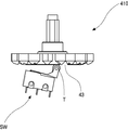
도 12(a)에는 본 발명에서 사용되는 종동기어(410)의 저면에서 바라본 종동기어(410)의 외관사시도가 도시되어 있으며, 도 12(b)에는 종동기어(410)의 정면도가 도시되어 있으며, 도 12(c)에는 마이크로 스위치(SW)와 종동기어(410)의 체결 관계를 보여주는 도면이 도시되어 있다. 12 (a) is an external perspective view of the driven
도 12(a)와 12(b)에서 알 수 있듯이, 저면에서 바라본 종동기어(410)는 원판형의 바디부(46)와, 상기 바디부(46)의 외주면을 따라 상기 바디부(46) 보다 더 두꺼운 형태로 형성되는 외주부(45)와, 상기 외주부(45)의 외측을 따라 형성되어 있 는 다수개의 기어 이(gear tooth)로 구성되어 있음을 알 수 있다. 그리고, 외주부(46)의 일측에는 깊이가 기어 이 정도인 홈(43)이 형성되어 있다. 12 (a) and 12 (b), the driven
한편, 도 12(c)에 도시된 바와 같이, 마이크로 스위치(SW)는 마이크로 스위치(SW)의 온/오프를 가능하게 하는 단자(T)가 종동기어(410)의 외주부(45)와 맞닿아 있는 상태가 되도록 상기 종동기어(410)의 하부에 위치한다. On the other hand, as shown in Figure 12 (c), the micro switch (SW) has a terminal (T) enabling the on / off of the micro switch (SW) in contact with the outer
상기 마이크로 스위치(SW)는 상기 단자(T)가 홈(43)에 위치하는 경우에만 오프 상태가 되고 그 외의 경우 즉 홈(43)이 형성되어 있는 부분을 제외한 외주부(45)와 맞닿아 있는 경우에는 온 상태를 유지한다. The micro switch SW is turned off only when the terminal T is located in the
따라서, 종동기어(410)가 회전하는 경우, 마이크로 스위치(SW)는 단자(T)가 는 홈(43)에 위치하는 경우를 제외하고는 온 상태를 유지하게 된다.Therefore, when the driven
제어부에서는 상기 마이크로 스위치(SW)가 오프인 시점으로부터 온 상태를 거쳐 다시 오프 상태가 되기까지의 시간을 검출하여 집진 용기내에 쌓여진 이물의 양을 판단하게 된다.The control unit detects a time from the time when the micro switch SW is off to the off state through the on state and determines the amount of foreign matter accumulated in the dust collecting container.
이에 대하여는 도 13 내지 도 15를 참조하여 설명하기로 한다. This will be described with reference to FIGS. 13 to 15.
도 13(a)와 도 13(b)는 이물을 압착하기 위한 제 1 가압판(310)이 제 2 가압판(320)의 좌측에 근접한 경우의 마이크로 스위치(SW)의 온 상태를 설명하기 위한 도면이고, 도 14(a)와 도 14(b)는 제 1 가압판(310)과 제 2 가압판(320)이 일직선상에 위치하는 경우의 마이크로 스위치(SW)의 오프 상태를 설명하기 위한 도면이고, 도 15(a)와 도 15(b)는 제 1 가압판(310)이 제 2 가압판(320)의 우측에 근접한 경우의 마이크로 스위치(SW)의 온 상태를 설명하기 위한 도면이다. 13 (a) and 13 (b) are views for explaining an on state of the micro switch SW when the first
도 13 내지 도 15에서 알 수 있듯이, 본 발명에서는 제 1 가압판(310)이 제 2 가압판(320)을 기준으로 180도 회전하여 일전선상에 위치하는 경우에 마이크로 스위치(SW)의 단자(T)가 종동기어(410)의 홈(43)에 위치하여 마이크로 스위치(SW)가 오프 상태가 된다. 마이크로 스위치(SW)가 오프 상태가 되는 도 14(a)에 도시된 제 1 가압판(310)의 위치를 설명의 편의상 기준 위치라고 한다. 13 to 15, in the present invention, when the first
제 1 가압판(310)이 기준 위치로부터 반시계 방향으로 회전하면서 집진 용기(220)내에 쌓인 이물을 압착하는 동안, 마이크로 스위치(SW)의 단자(T)는 홈(43)이 없는 종동기어(410)의 외주부(45)와 맞닿게 되므로 도 13(b)에서 알 수 있는 바와 같이 마이크로 스위치(SW)는 온 상태가 된다. While the first
반시계 방향으로 회전하던 제 1 가압판(310)이 이물의 영향으로 더 이상 회전하지 못하게 되면, 압축 모터(870)는 시계 방향으로 다시 방향으로 회전하게 된다. 그 결과, 제 1 가압판(310)은 시계 방향으로 회전하게 된다. 따라서, 제 1 가압판(310)은 도 14(a)에 도시된 기준 위치를 지나 도 15(a)과 같이 제 2 가압판(320)의 우측으로 회전하면서 집진용기(220) 내에 쌓인 이물을 압착하게 된다. When the
시계 방향으로 회전하던 제 1 가압판(310)이 이물의 영향으로 더 이상 회전하지 못하게 되면, 압축 모터(870)는 반시계 방향으로 다시 방향으로 회전하면서 지금까지 설명한 과정을 반복 수행하면서 집진 용기(220) 내에 쌓인 이물을 압착하면서 집진 효율을 극대화시킬 것이다. When the
도 16은 도 13 내지 도 15에서 설명한 제 1 가압판(310)의 회전 동작을 총괄적으로 설명하기 위한 도면이다. FIG. 16 is a view for collectively explaining the rotation operation of the first
도 16에는, 제 1 가압판(310)이 기준 위치로부터 시계방향으로 회전하여 다시 기준위치까지 복귀하기까지 소요되는 시간(TD1)과, 제 1 가압판(310)이 기준 위치로부터 반시계방향으로 회전하여 다시 기준위치까지 복귀하기까지 소요되는 시간(TD2)이 표시되어 있다. 설명의 편의상, 시간(TD1)을 제 1 왕복시간, 시간(TD2)를 제 2 왕복시간이라고 한다. 통상, 이물은 집진용기(220) 내부에 골고루 퍼지게 되므로 제 1 왕복시간(TD1)과 제 2 왕복시간(TD2)은 거의 동일하다고 할 수 있다. In FIG. 16, the time TD1 takes for the
한편, 제 1 가압판(310)에 의하여 압착되는 이물의 양이 증가할수록 제 1 왕복시간(TD1)과 제 2 왕복시간(TD2)은 점점 단축된다. Meanwhile, as the amount of foreign matter compressed by the first
본 발명에서는 상기 제 1 왕복시간(TD1)과 제 2 왕복시간(TD2)중의 어느 하나가 소정의 기준 시간이 도달하는 경우 집진 용기(220)내에 이물이 충분히 쌓였다고 판단하여 이물을 비우라는 신호가 표시되도록 한다. In the present invention, when any one of the first round trip time (TD1) and the second round trip time (TD2) reaches a predetermined reference time, it is determined that the foreign material has accumulated enough in the
도 17은 본 발명에서 제안하는 진공청소기의 제어 방법을 설명하는 흐름도이다. 17 is a flowchart illustrating a control method of the vacuum cleaner proposed in the present invention.
처음, 사용자는 동작신호 입력부(820)에 표시되어 있는 흡입 파워인 강, 중, 약 모드 중의 하나를 선택하여 진공 청소기를 작동시킨다. 제어부(810)는 사용자가 선택한 흡입 모드에 따라 흡입 모터(850)가 구동되도록 흡입모터 드라이버(840)를 작동시킨다(S110).First, the user selects one of the strong, medium, and weak modes of suction power displayed on the operation
상기 흡입 모터(850)가 작동하면 상기 흡입 모터(850)의 흡입력에 의하여 먼지 등과 같은 이물이 흡입 노즐(20)을 통하여 흡입된다. 이렇게 흡입된 이물은 집진 유닛에 모이게 된다. 보다 구체적으로 표현하면, 집진 용기(220)에 모이게 된 다. When the
전술한 바와 같이, 본 발명에서는 집진 용기(220) 내부에 쌓이는 이물을 가압판(310, 320)을 이용하여 압축하는 동작을 수행하게 된다. As described above, in the present invention, foreign matters accumulated in the
따라서, 제어부(810)는 상기 집진 용기에 흡입된 이물을 압축시키기 위하여 압축모터(870)를 구동시킨다(S120).Therefore, the
참고로, 본 발명에서는 흡입모터(850)의 구동 후에 압축 모터(870)를 구동하는 방식을 취하였으나, 다른 실시예로서 흡입모터(850)와 압축모터(870)를 동시에 작동시킬 수도 있을 것이다. For reference, in the present invention, the driving method of the
단계(S120)에서, 상기 압축모터(870)가 구동되면, 압축모터(870)의 회전축과 축결합되어 있는 구동기어(420)가 회전한다. 구동기어(420)가 회전하면 이에 연동되어 종동기어(410)가 회전하기 시작한다. 상기 종동 기어(410)가 회전하면 종동기어(410)과 체결되어 있는 상기 회전축(312) 및 제 1 가압판(310)이 자동적으로 제 2 가압판(320) 쪽으로 회전 이동하면서 이물을 압착하게 된다. In operation S120, when the
이때, 제어부(810)는 제 1 가압판(310)이 기준 위치에 위치하는지 여부를 우선 체크한다(S130). 본 발명은 제 1 가압판(310)의 기준 위치를 기준으로 하여 제 1 및 제 2 왕복시간을 측정하는 것이므로, 최초 동작시, 제 1 가압판(310)을 기준위치에 있다는 것을 확인할 필요가 있다. 제 1 가압판(310)이 기준 위치에 위치한다는 것은 최초 동작시 마이크로 스위치(SW)가 처음으로 오프되는 시점일 것이다. 따라서, 제어부(810)는 마이크로 스위치(SW)가 처음 오프되는 시점을 기준으로하여 제 1 왕복시간 또는 제 2 왕복시간을 측정하게 된다. At this time, the
제 1 가압판(310)이 기준위치에 이동한 시점을 시작으로 제어부(810)는 제 1 가압판(310)의 시계 방향으로의 이동 또는 반시계 방향으로 이동에 따라서, 제 1 왕복시간(TD1)과 제 2 왕복시간(TD2)을 측정한다(S140) Starting from the point in time when the first
상기 제 1 가압판(310)과 제 2 가압판(320)에 의하여 집진 유닛 내부에서 압착되는 이물의 양이 증가할수록 종동 기어(410)의 좌우 왕복 회전 시간이 짧아진다. As the amount of the foreign matter compressed in the dust collecting unit by the first
제어부(810)는 마이크로 스위치(SW)를 통하여 제 1 가압판(310)의 제 1 왕복시간(TD1)과 제 2 왕복시간(TD2)을 측정하면서, 상기 제 1 왕복시간(TD1) 또는 제 2 왕복시간(TD2)이 소정의 기준 시간에 도달하였는지 여부를 판단한다(S150). 여기서, 소정의 기준 시간은 설계자에 의하여 제어부(810) 자체에 설정한 시간으로서, 이는 기준 집진용기(220)내에 이물이 일정량 이상 쌓였다고 판단하는 근거가 된다. 상기 기준 시간은 설계자가 다수회 반복 실험하여 얻어지는 것으로써 진공청소기의 용량에 따라 달라진다. The
본 발명의 경우, 제 1 왕복시간(TD1) 또는 제 2 왕복시간(TD2) 중의 어느 하나가 기준 시간에 도달하는 경우, 이물의 양이 소정량에 도달하였다고 판단하는 방식을 취하였으나, 다른 실시예로서, 그 판단 근거를 제 1 왕복시간(TD1)과 제 2 왕복시간(TD2)이 모두 소정의 기준 시간 이내에 도달한 경우로 할 수도 있을 것이다. In the present invention, when either the first round trip time (TD1) or the second round trip time (TD2) reaches the reference time, it took a way to determine that the amount of foreign matter has reached a predetermined amount, another embodiment The reason for the determination may be the case where both the first round trip time TD1 and the second round trip time TD2 have reached within a predetermined reference time.
단계(S150)에서의 판단 결과, 제 1 왕복시간(TD1)과 제 2 왕복시간(TD2)중의 어느 하나라도 기준 시간보다 긴 경우에는 단계(S140)을 으로 복귀하여 이전의 과정을 수행한다.As a result of the determination in step S150, if any one of the first round trip time TD1 and the second round trip time TD2 is longer than the reference time, step S140 is returned to and the previous process is performed.
이에 대하여 제 1 왕복시간(TD1) 또는 제 2 왕복시간(TD2)이 기준 시간에 도달한 경우, 제어부(810)는 흡입 모터(850)를 오프시켜 이물 흡입 동작을 정지시킨다(S160). 흡입모터(850)를 강제적으로 정지시키는 이유는 집진 용기(220) 내부에 쌓인 이물의 양이 소정 양을 초과한 경우에 강제적으로 이물 흡입 동작을 계속하게 되면 이물 흡입 효율이 떨어질 뿐만 아니라 흡입모터(850)에도 과부하가 걸릴 수 있기 때문이다. 이때, 압축모터(870)도 함께 오프되도록 제어하는것이 바람직할 것이다. In contrast, when the first round trip time TD1 or the second round trip time TD2 reaches the reference time, the
다음, 제어부(810)는 집진 유닛 내의 이물을 비우라는 신호를 먼지교환신호 표시부(830)로 전송하여 사용자가 인식할 수 있도록 한다. 본 발명의 다른 실시예로서, 먼지교환신호는 부저 회로를 이용하여 소정의 소리 신호로 표시할 수도 있을 것이다.Next, the
본 발명의 경우, 집진 유닛의 이물 비움 시기가 사용자에게 알려짐에 따라 사용자의 편의성이 증대되고, 이렇게 이물 비움 알림 기능이 수행되는 과정에서 흡입 모터의 작동이 조절되도록 함으로써, 과도한 이물의 흡입에 따른 상기 청소기의 작동 성능이 저하되는 것이 방지된다. In the case of the present invention, the user's convenience is increased as the foreign body emptying time of the dust collecting unit is known to the user, and the operation of the suction motor is controlled in the process of performing the foreign material emptying notification function, thereby causing the above-mentioned according to excessive foreign material inhalation. The deterioration of the operating performance of the cleaner is prevented.
한편, 지금까지 설명한 본 발명의 기술적 사상은 업라이트 형의 청소기나 로봇 청소기에도 적용할 수 있다. Meanwhile, the technical idea of the present invention described so far can be applied to an upright cleaner or a robot cleaner.
제안되는 바와 같은 본 발명에 의하면, 다음과 같은 효과가 있다. According to the present invention as proposed, the following effects are obtained.
첫째, 본 발명에 따른 진공 청소기에 의하면, 한 쌍의 가압판에 의해서 상기 집진 유닛 내부에 저장되는 이물이 압축되어 그 부피가 최소화되므로, 상기 집진 유닛 내부에 저장되는 이물의 집진 용량이 최대화되는 효과가 있다. First, according to the vacuum cleaner according to the present invention, since the foreign matter stored in the dust collecting unit is compressed by a pair of pressure plates to minimize the volume, the dust collecting capacity of the foreign matter stored in the dust collecting unit is maximized. have.
둘째, 상기 한 쌍의 가압판의 압축 작용에 의해서 상기 집진 유닛의 집진 용량이 최대화됨에 따라 사용자가 상기 집진 유닛의 내부에 저장된 이물을 자주 비워줘야 하는 번거로움이 제거되는 효과가 있다. Secondly, as the dust collecting capacity of the dust collecting unit is maximized by the compression action of the pair of pressure plates, the user has to remove the trouble of frequently emptying the foreign matter stored in the dust collecting unit.
셋째, 상기 집진 유닛 내부에 집진된 이물이 진공 청소기의 작동이 정지된 경우에도 압축된 상태를 유지함에 따라, 이물의 비움시 상기 집진 유닛 내부에 저장된 이물이 상기 집진 유닛 외부로 쉽게 배출되게 된다. Third, as the foreign matter collected in the dust collecting unit maintains a compressed state even when the operation of the vacuum cleaner is stopped, foreign matter stored in the dust collecting unit is easily discharged to the outside of the dust collecting unit when the foreign matter is emptied.
넷째, 상기 집진 유닛 내부에 소정량 이상의 이물이 집진되면, 상기 집진 유닛의 이물 비움 시기가 표시되어 사용자가 이물을 비우는 시기를 쉽게 알 수 있는 효과가 있다. Fourth, when the foreign matter is collected in a predetermined amount or more inside the dust collection unit, the foreign material emptying time of the dust collecting unit is displayed, there is an effect that the user can easily know when to empty the foreign material.
다섯째, 상기 집진 유닛의 이물 비움 시기가 표시됨과 아울러 제 1 회전판이 이물의 비움이 용이한 위치로 이동됨에 따라 사용자가 편리하게 이물을 비울 수 있게 되는 효과가 있다. Fifth, as the foreign material emptying time of the dust collecting unit is displayed and the first rotating plate is moved to a position where the foreign material is easily removed, there is an effect that the user can conveniently empty the foreign material.
Claims (4)
Priority Applications (26)
| Application Number | Priority Date | Filing Date | Title |
|---|---|---|---|
| KR1020060098191A KR100833362B1 (en) | 2006-10-10 | 2006-10-10 | How to control the vacuum cleaner |
| US11/565,241 US7749295B2 (en) | 2005-12-10 | 2006-11-30 | Vacuum cleaner with removable dust collector, and methods of operating the same |
| US11/565,206 US7882592B2 (en) | 2005-12-10 | 2006-11-30 | Vacuum cleaner |
| EP20070101387 EP1859719B1 (en) | 2006-05-23 | 2007-01-30 | Vacuum cleaner and controlling method of the same |
| RU2007103559/11A RU2328200C1 (en) | 2006-10-10 | 2007-01-30 | Vacuum cleaner and way of operating it (variant) |
| AU2007200409A AU2007200409B2 (en) | 2006-05-23 | 2007-01-31 | Vacuum cleaner and controlling method of the same |
| US11/713,022 US7601188B2 (en) | 2005-12-10 | 2007-03-02 | Vacuum cleaner |
| US11/712,958 US7582128B2 (en) | 2005-12-10 | 2007-03-02 | Vacuum cleaner |
| CN200710085701XA CN101077286B (en) | 2006-05-23 | 2007-03-06 | Vacuum cleaner and controlling method of the same |
| JP2007066748A JP4625039B2 (en) | 2006-05-23 | 2007-03-15 | Vacuum cleaner and control method thereof |
| US11/831,564 US7770253B2 (en) | 2005-12-10 | 2007-07-31 | Vacuum cleaner with removable dust collector, and methods of operating the same |
| US11/831,519 US7785396B2 (en) | 2005-12-10 | 2007-07-31 | Vacuum cleaner with removable dust collector, and methods of operating the same |
| US11/831,473 US8060979B2 (en) | 2005-12-10 | 2007-07-31 | Vacuum cleaner with removable dust collector, and methods of operating the same |
| CA 2598113 CA2598113C (en) | 2006-09-06 | 2007-08-17 | Vacuum cleaner with removable dust collector |
| CA 2598117 CA2598117C (en) | 2006-09-06 | 2007-08-17 | Vacuum cleaner with removable dust collector, and methods of operating the same |
| US12/404,715 US8240001B2 (en) | 2005-12-10 | 2009-03-16 | Vacuum cleaner with removable dust collector, and methods of operating the same |
| US12/404,739 US8021452B2 (en) | 2005-12-10 | 2009-03-16 | Vacuum cleaner with removable dust collector, and methods of operating the same |
| US12/404,692 US8312593B2 (en) | 2005-12-10 | 2009-03-16 | Vacuum cleaner with removable dust collector, and methods of operating the same |
| US12/407,224 US7998234B2 (en) | 2005-12-10 | 2009-03-19 | Vacuum cleaner with removable dust collector, and methods of operating the same |
| US12/407,293 US8043410B2 (en) | 2005-12-10 | 2009-03-19 | Vacuum cleaner with removable dust collector, and methods of operating the same |
| US12/407,243 US8544143B2 (en) | 2005-12-10 | 2009-03-19 | Vacuum cleaner with removable dust collector, and methods of operating the same |
| US12/407,267 US8043397B2 (en) | 2005-12-10 | 2009-03-19 | Vacuum cleaner with removable dust collector, and methods of operating the same |
| US12/408,066 US7987551B2 (en) | 2005-12-10 | 2009-03-20 | Vacuum cleaner |
| US12/407,964 US8012250B2 (en) | 2005-12-10 | 2009-03-20 | Vacuum cleaner |
| US12/407,983 US8404034B2 (en) | 2005-12-10 | 2009-03-20 | Vacuum cleaner and method of controlling the same |
| US12/407,975 US8281455B2 (en) | 2005-12-10 | 2009-03-20 | Vacuum cleaner |
Applications Claiming Priority (1)
| Application Number | Priority Date | Filing Date | Title |
|---|---|---|---|
| KR1020060098191A KR100833362B1 (en) | 2006-10-10 | 2006-10-10 | How to control the vacuum cleaner |
Publications (2)
| Publication Number | Publication Date |
|---|---|
| KR20080032449A KR20080032449A (en) | 2008-04-15 |
| KR100833362B1 true KR100833362B1 (en) | 2008-05-28 |
Family
ID=39533212
Family Applications (1)
| Application Number | Title | Priority Date | Filing Date |
|---|---|---|---|
| KR1020060098191A Expired - Fee Related KR100833362B1 (en) | 2005-12-10 | 2006-10-10 | How to control the vacuum cleaner |
Country Status (2)
| Country | Link |
|---|---|
| KR (1) | KR100833362B1 (en) |
| RU (1) | RU2328200C1 (en) |
Citations (4)
| Publication number | Priority date | Publication date | Assignee | Title |
|---|---|---|---|---|
| JPS5485560A (en) * | 1977-12-20 | 1979-07-07 | Tokyo Electric Co Ltd | Electric cleaner |
| KR19990050243A (en) * | 1997-12-16 | 1999-07-05 | 구자홍 | Dust filter replacement alarm device and method |
| KR19990055544A (en) * | 1997-12-27 | 1999-07-15 | 최진호 | Dust display device of the central vacuum cleaner |
| KR20070088023A (en) * | 2006-02-24 | 2007-08-29 | 엘지전자 주식회사 | Operation Method of Dust Compaction Dust Collector |
Family Cites Families (4)
| Publication number | Priority date | Publication date | Assignee | Title |
|---|---|---|---|---|
| SU372992A1 (en) * | 1971-01-08 | 1973-03-12 | Всесоюзный научно исследовательский институт электробытовым машинам , приборам | A VACUUM CLEANER |
| SU745497A1 (en) * | 1978-07-14 | 1980-07-05 | Днепропетровский Агрегатный Завод Им. 50-Летия Ссср | Vacuum cleaner dust-trap filling indicator |
| SU1326236A1 (en) * | 1986-02-03 | 1987-07-30 | Ю. Ф. Киселев, В. М. Опанасюк и А. В. Кр чек | Vacuum cleaner |
| KR100466319B1 (en) * | 2002-04-17 | 2005-01-13 | 삼성광주전자 주식회사 | Vacuum cleaner indicating the state of the input voltage |
-
2006
- 2006-10-10 KR KR1020060098191A patent/KR100833362B1/en not_active Expired - Fee Related
-
2007
- 2007-01-30 RU RU2007103559/11A patent/RU2328200C1/en active
Patent Citations (4)
| Publication number | Priority date | Publication date | Assignee | Title |
|---|---|---|---|---|
| JPS5485560A (en) * | 1977-12-20 | 1979-07-07 | Tokyo Electric Co Ltd | Electric cleaner |
| KR19990050243A (en) * | 1997-12-16 | 1999-07-05 | 구자홍 | Dust filter replacement alarm device and method |
| KR19990055544A (en) * | 1997-12-27 | 1999-07-15 | 최진호 | Dust display device of the central vacuum cleaner |
| KR20070088023A (en) * | 2006-02-24 | 2007-08-29 | 엘지전자 주식회사 | Operation Method of Dust Compaction Dust Collector |
Also Published As
| Publication number | Publication date |
|---|---|
| KR20080032449A (en) | 2008-04-15 |
| RU2328200C1 (en) | 2008-07-10 |
Similar Documents
| Publication | Publication Date | Title |
|---|---|---|
| JP4705052B2 (en) | Control method of vacuum cleaner | |
| JP4695102B2 (en) | Dust collector and vacuum cleaner | |
| KR100800189B1 (en) | Vacuum cleaner | |
| KR100853332B1 (en) | Vacuum cleaner, dust separation device of vacuum cleaner and control method of vacuum cleaner | |
| KR20070088022A (en) | Dust collector and vacuum cleaner having same | |
| JP4625039B2 (en) | Vacuum cleaner and control method thereof | |
| KR100871487B1 (en) | How to control the vacuum cleaner | |
| KR100809773B1 (en) | Vacuum cleaner control method | |
| KR100906848B1 (en) | Vacuum cleaner | |
| EP1825797A2 (en) | Method of controlling vacuum cleaner | |
| KR100833362B1 (en) | How to control the vacuum cleaner | |
| KR100992221B1 (en) | Vacuum cleaner | |
| KR100895145B1 (en) | How to control the vacuum cleaner | |
| KR101093941B1 (en) | Vacuum cleaner | |
| KR101026028B1 (en) | Vacuum cleaner | |
| KR100906849B1 (en) | Vacuum cleaner and its control method | |
| KR101136618B1 (en) | Control method of vacuum cleaner | |
| KR100813723B1 (en) | Vacuum cleaner and its control method | |
| KR100947360B1 (en) | Vacuum cleaner and its control method |
Legal Events
| Date | Code | Title | Description |
|---|---|---|---|
| PA0109 | Patent application |
St.27 status event code: A-0-1-A10-A12-nap-PA0109 |
|
| A201 | Request for examination | ||
| PA0201 | Request for examination |
St.27 status event code: A-1-2-D10-D11-exm-PA0201 |
|
| E701 | Decision to grant or registration of patent right | ||
| PE0701 | Decision of registration |
St.27 status event code: A-1-2-D10-D22-exm-PE0701 |
|
| PG1501 | Laying open of application |
St.27 status event code: A-1-1-Q10-Q12-nap-PG1501 |
|
| GRNT | Written decision to grant | ||
| PR0701 | Registration of establishment |
St.27 status event code: A-2-4-F10-F11-exm-PR0701 |
|
| PR1002 | Payment of registration fee |
St.27 status event code: A-2-2-U10-U11-oth-PR1002 Fee payment year number: 1 |
|
| PG1601 | Publication of registration |
St.27 status event code: A-4-4-Q10-Q13-nap-PG1601 |
|
| PN2301 | Change of applicant |
St.27 status event code: A-5-5-R10-R13-asn-PN2301 St.27 status event code: A-5-5-R10-R11-asn-PN2301 |
|
| R18-X000 | Changes to party contact information recorded |
St.27 status event code: A-5-5-R10-R18-oth-X000 |
|
| R18-X000 | Changes to party contact information recorded |
St.27 status event code: A-5-5-R10-R18-oth-X000 |
|
| FPAY | Annual fee payment |
Payment date: 20110418 Year of fee payment: 4 |
|
| PR1001 | Payment of annual fee |
St.27 status event code: A-4-4-U10-U11-oth-PR1001 Fee payment year number: 4 |
|
| FPAY | Annual fee payment |
Payment date: 20120424 Year of fee payment: 5 |
|
| PR1001 | Payment of annual fee |
St.27 status event code: A-4-4-U10-U11-oth-PR1001 Fee payment year number: 5 |
|
| FPAY | Annual fee payment |
Payment date: 20130424 Year of fee payment: 6 |
|
| PR1001 | Payment of annual fee |
St.27 status event code: A-4-4-U10-U11-oth-PR1001 Fee payment year number: 6 |
|
| FPAY | Annual fee payment |
Payment date: 20140424 Year of fee payment: 7 |
|
| PR1001 | Payment of annual fee |
St.27 status event code: A-4-4-U10-U11-oth-PR1001 Fee payment year number: 7 |
|
| FPAY | Annual fee payment |
Payment date: 20150424 Year of fee payment: 8 |
|
| PR1001 | Payment of annual fee |
St.27 status event code: A-4-4-U10-U11-oth-PR1001 Fee payment year number: 8 |
|
| PN2301 | Change of applicant |
St.27 status event code: A-5-5-R10-R13-asn-PN2301 St.27 status event code: A-5-5-R10-R11-asn-PN2301 |
|
| FPAY | Annual fee payment |
Payment date: 20160422 Year of fee payment: 9 |
|
| PR1001 | Payment of annual fee |
St.27 status event code: A-4-4-U10-U11-oth-PR1001 Fee payment year number: 9 |
|
| FPAY | Annual fee payment |
Payment date: 20170414 Year of fee payment: 10 |
|
| PR1001 | Payment of annual fee |
St.27 status event code: A-4-4-U10-U11-oth-PR1001 Fee payment year number: 10 |
|
| P22-X000 | Classification modified |
St.27 status event code: A-4-4-P10-P22-nap-X000 |
|
| PR1001 | Payment of annual fee |
St.27 status event code: A-4-4-U10-U11-oth-PR1001 Fee payment year number: 11 |
|
| PR1001 | Payment of annual fee |
St.27 status event code: A-4-4-U10-U11-oth-PR1001 Fee payment year number: 12 |
|
| FPAY | Annual fee payment |
Payment date: 20200414 Year of fee payment: 13 |
|
| PR1001 | Payment of annual fee |
St.27 status event code: A-4-4-U10-U11-oth-PR1001 Fee payment year number: 13 |
|
| PN2301 | Change of applicant |
St.27 status event code: A-5-5-R10-R13-asn-PN2301 St.27 status event code: A-5-5-R10-R11-asn-PN2301 |
|
| FPAY | Annual fee payment |
Payment date: 20210414 Year of fee payment: 14 |
|
| PR1001 | Payment of annual fee |
St.27 status event code: A-4-4-U10-U11-oth-PR1001 Fee payment year number: 14 |
|
| LAPS | Lapse due to unpaid annual fee | ||
| PC1903 | Unpaid annual fee |
St.27 status event code: A-4-4-U10-U13-oth-PC1903 Not in force date: 20220523 Payment event data comment text: Termination Category : DEFAULT_OF_REGISTRATION_FEE |
|
| PC1903 | Unpaid annual fee |
St.27 status event code: N-4-6-H10-H13-oth-PC1903 Ip right cessation event data comment text: Termination Category : DEFAULT_OF_REGISTRATION_FEE Not in force date: 20220523 |