KR100800189B1 - Vacuum cleaner - Google Patents
Vacuum cleaner Download PDFInfo
- Publication number
- KR100800189B1 KR100800189B1 KR1020070015806A KR20070015806A KR100800189B1 KR 100800189 B1 KR100800189 B1 KR 100800189B1 KR 1020070015806 A KR1020070015806 A KR 1020070015806A KR 20070015806 A KR20070015806 A KR 20070015806A KR 100800189 B1 KR100800189 B1 KR 100800189B1
- Authority
- KR
- South Korea
- Prior art keywords
- dust
- pressing member
- dust collecting
- unit
- magnetic
- Prior art date
- Legal status (The legal status is an assumption and is not a legal conclusion. Google has not performed a legal analysis and makes no representation as to the accuracy of the status listed.)
- Expired - Fee Related
Links
Images


Classifications
-
- A—HUMAN NECESSITIES
- A47—FURNITURE; DOMESTIC ARTICLES OR APPLIANCES; COFFEE MILLS; SPICE MILLS; SUCTION CLEANERS IN GENERAL
- A47L—DOMESTIC WASHING OR CLEANING; SUCTION CLEANERS IN GENERAL
- A47L9/00—Details or accessories of suction cleaners, e.g. mechanical means for controlling the suction or for effecting pulsating action; Storing devices specially adapted to suction cleaners or parts thereof; Carrying-vehicles specially adapted for suction cleaners
- A47L9/10—Filters; Dust separators; Dust removal; Automatic exchange of filters
- A47L9/19—Means for monitoring filtering operation
-
- A—HUMAN NECESSITIES
- A47—FURNITURE; DOMESTIC ARTICLES OR APPLIANCES; COFFEE MILLS; SPICE MILLS; SUCTION CLEANERS IN GENERAL
- A47L—DOMESTIC WASHING OR CLEANING; SUCTION CLEANERS IN GENERAL
- A47L9/00—Details or accessories of suction cleaners, e.g. mechanical means for controlling the suction or for effecting pulsating action; Storing devices specially adapted to suction cleaners or parts thereof; Carrying-vehicles specially adapted for suction cleaners
- A47L9/10—Filters; Dust separators; Dust removal; Automatic exchange of filters
- A47L9/106—Dust removal
- A47L9/108—Dust compression means
-
- A—HUMAN NECESSITIES
- A47—FURNITURE; DOMESTIC ARTICLES OR APPLIANCES; COFFEE MILLS; SPICE MILLS; SUCTION CLEANERS IN GENERAL
- A47L—DOMESTIC WASHING OR CLEANING; SUCTION CLEANERS IN GENERAL
- A47L9/00—Details or accessories of suction cleaners, e.g. mechanical means for controlling the suction or for effecting pulsating action; Storing devices specially adapted to suction cleaners or parts thereof; Carrying-vehicles specially adapted for suction cleaners
- A47L9/10—Filters; Dust separators; Dust removal; Automatic exchange of filters
- A47L9/16—Arrangement or disposition of cyclones or other devices with centrifugal action
- A47L9/1683—Dust collecting chambers; Dust collecting receptacles
-
- A—HUMAN NECESSITIES
- A47—FURNITURE; DOMESTIC ARTICLES OR APPLIANCES; COFFEE MILLS; SPICE MILLS; SUCTION CLEANERS IN GENERAL
- A47L—DOMESTIC WASHING OR CLEANING; SUCTION CLEANERS IN GENERAL
- A47L9/00—Details or accessories of suction cleaners, e.g. mechanical means for controlling the suction or for effecting pulsating action; Storing devices specially adapted to suction cleaners or parts thereof; Carrying-vehicles specially adapted for suction cleaners
- A47L9/28—Installation of the electric equipment, e.g. adaptation or attachment to the suction cleaner; Controlling suction cleaners by electric means
- A47L9/2805—Parameters or conditions being sensed
Landscapes
- Engineering & Computer Science (AREA)
- Mechanical Engineering (AREA)
- Filters For Electric Vacuum Cleaners (AREA)
Abstract
본 발명은 진공 청소기에 관한 것으로서, 상세하게는 집진 장치의 집진 용량이 최대화되는 진공 청소기에 관한 것이다. The present invention relates to a vacuum cleaner, and more particularly, to a vacuum cleaner in which a dust collecting capacity of a dust collecting device is maximized.
본 발명에 따른 진공 청소기는 집진 장치 장착부가 형성되는 청소기 본체; 상기 집진 장치 장착부에 착탈 가능하며, 내부에 먼지 저장부가 형성되는 집진 장치; 상기 먼지 저장부 내에서 이동 가능하게 구비되어, 상기 먼지 저장부에 저장된 먼지의 부피를 감소시키는 적어도 하나의 가압 부재; 상기 가압 부재에 연결되어, 외부로부터 전달되는 구동력을 상기 가압 부재로 전달하는 동력 전달부; 상기 동력 전달부에 제공되는 자성 부재; 상기 자성 부재의 자기를 감지하는 자기 감지부; 및 상기 자기 감지부의 자기 여부에 의해서 상기 먼지 저장부 내부의 먼지 저장량을 판단하는 제어부가 포함된다. Vacuum cleaner according to the present invention comprises a cleaner body in which the dust collector mounting portion is formed; A dust collector detachable from the dust collector mounting unit and having a dust storage unit formed therein; At least one pressing member movably provided in the dust storage unit to reduce a volume of dust stored in the dust storage unit; A power transmission unit connected to the pressing member and transmitting a driving force transmitted from the outside to the pressing member; A magnetic member provided in the power transmission unit; A magnetic sensing unit for sensing magnetism of the magnetic member; And a controller configured to determine the amount of dust stored in the dust storage unit based on whether or not the magnetic sensing unit is magnetic.
이와 같은 본 발명에 의하면, 가압 부재에 의해서 상기 집진 장치 내부에 저장되는 먼지가 압축되어 그 부피가 최소화되므로, 상기 집진 장치 내부에 저장되는 먼지의 집진 용량이 최대화되는 효과가 있고, 먼지 저장부에 저장된 먼지 저장량이 판단됨에 따라 먼지 비움 시기를 외부로 표시할 수 있게되어 사용자의 편의성이 증대되는 효과가 있다. According to the present invention, since the dust stored in the dust collector is compressed by the pressing member to minimize the volume, the dust collecting capacity of the dust stored in the dust collector is maximized, and the dust storage unit As the stored dust storage amount is determined, the dust emptying time can be displayed to the outside, thereby increasing user convenience.
Description
도 1은 본 발명에 따른 진공 청소기의 사시도.1 is a perspective view of a vacuum cleaner according to the present invention.
도 2는 상기 진공 청소기에서 집진 장치가 분리된 상태의 사시도.Figure 2 is a perspective view of a state in which the dust collector is separated from the vacuum cleaner.
도 3은 본 발명에 따른 집진 장치의 사시도.3 is a perspective view of a dust collecting device according to the present invention.
도 4는 도 3의 I-I'를 따라 절개한 단면도.4 is a cross-sectional view taken along the line II ′ of FIG. 3.
도 5는 본 발명에 따른 집진 장치의 하부 사시도.5 is a bottom perspective view of the dust collecting device according to the present invention.
도 6은 본 발명에 따른 종동 기어의 하부 사시도.Figure 6 is a bottom perspective view of the driven gear in accordance with the present invention.
도 7은 본 발명에 따른 집진 장치 장착부의 사시도.Figure 7 is a perspective view of the dust collector mounting portion according to the present invention.
도 8은 본 발명에 따른 진공 청소기의 제어 장치를 보여주는 블럭도.8 is a block diagram showing an apparatus for controlling a vacuum cleaner according to the present invention.
도 9와 도 10은 먼지를 압축하기 위한 제 1 가압 부재가 제 2 가압 부재의 일측에 근접한 경우의 자성 부재와 자기 감지 소자의 위치 관계를 설명하기 위한 도면.9 and 10 are views for explaining the positional relationship between the magnetic member and the magnetic sensing element when the first pressing member for compressing the dust is close to one side of the second pressing member.
도 11과 도 12는 제 1 가압 부재와 제 2 가압 부재가 일직선상에 위치하는 경우의 자성 부재와 자기 감지 소자의 위치 관계를 설명하기 위한 도면.11 and 12 are views for explaining the positional relationship between the magnetic member and the magnetic sensing element when the first pressing member and the second pressing member are in a straight line.
도 13과 도 14는 제 1 가압 부재가 제 2 가압 부재의 타측에 근접한 경우의 자성 부재와 자기 감지 소자의 위치 관계를 설명하기 위한 도면.13 and 14 are views for explaining the positional relationship between the magnetic member and the magnetic sensing element when the first pressing member is close to the other side of the second pressing member.
도 15는 도 9 내지 도 14에서 설명한 제 1 가압 부재의 회전 동작을 총괄적 으로 설명하기 위한 도면.15 is a view for collectively explaining the rotation operation of the first pressing member described with reference to FIGS. 9 to 14.
도 16은 본 발명에 따른 진공 청소기의 제어 방법을 설명하는 흐름도.16 is a flowchart illustrating a control method of the vacuum cleaner according to the present invention.
<도면의 주요 부분에 대한 부호의 설명><Explanation of symbols for the main parts of the drawings>
100 : 본체 200 : 집진 장치100: main body 200: dust collector
270 : 제 1 가압 부재 280 : 제 2 가압 부재270: first pressing member 280: second pressing member
410 : 종동 기어 416 : 자성 부재410: driven gear 416: magnetic member
420 : 구동 기어 440 : 자기 감지 소자420: drive gear 440: magnetic sensing element
870 : 압축 모터870: Compression Motor
본 발명은 진공 청소기에 관한 것으로서, 상세하게는 집진 장치의 집진 용량이 최대화되는 진공 청소기에 관한 것이다. The present invention relates to a vacuum cleaner, and more particularly, to a vacuum cleaner in which a dust collecting capacity of a dust collecting device is maximized.
일반적으로 진공 청소기는 본체 내부에 장착되는 진공 모터에 의하여 발생되는 진공압을 이용하여, 먼지가 포함된 공기를 흡입한 다음, 본체 내부에서 먼지를 필터링하는 장치이다. In general, a vacuum cleaner is a device that sucks air containing dust by using a vacuum pressure generated by a vacuum motor mounted inside the body, and then filters the dust inside the body.
이러한 진공 청소기는, 먼지가 포함된 공기를 흡입하기 위한 흡입 노즐, 상기 흡입 노즐과 연통하는 청소기 본체, 상기 흡입 노즐에서 흡입된 공기를 상기 청소기 본체 측으로 안내하는 연장관, 및 상기 연장관을 거친 공기를 상기 청소기 본체에 연결하는 연결관이 포함된다. The vacuum cleaner may include a suction nozzle for sucking air containing dust, a cleaner body in communication with the suction nozzle, an extension pipe for guiding air sucked from the suction nozzle toward the cleaner body, and air passing through the extension pipe. A connector is connected to the cleaner body.
여기서, 상기 흡입 노즐의 바닥에는 소정 크기의 노즐 흡입구가 형성되어, 바닥에 쌓인 먼지가 포함된 공기가 흡입되도록 한다.Here, a nozzle suction port having a predetermined size is formed at the bottom of the suction nozzle to allow the air containing the dust accumulated on the floor to be sucked.
한편, 상기 청소기 본체의 내부에는, 상기 흡입 노즐로 먼지가 포함된 외부의 공기가 흡입되도록 공기 흡입력을 발생시키는 구동 유닛이 구비된다.On the other hand, the inside of the cleaner body, a driving unit for generating an air suction force to suck the outside air containing dust to the suction nozzle is provided.
그리고, 상기 청소기 본체에는 먼지를 분리하여 저장하는 집진 장치가 분리 가능하게 장착된다. 상기 집진 장치는 상기 흡입노즐에서 흡입된 공기에 포함된 먼지를 분리하여 저장하는 기능을 수행한다.In addition, the dust collector is detachably mounted to the cleaner body to separate and store dust. The dust collector performs a function of separating and storing dust contained in the air sucked from the suction nozzle.
상세히, 상기 집진 장치는, 집진 바디와, 상기 집진 바디로 공기가 흡입되도록 하는 흡입구와, 상기 집진 바디로 흡입되는 공기 중에서 먼지를 분리시키는 싸이클론부와, 상기 싸이클론부에서 분리된 먼지가 저장되는 먼지 저장부와, 상기 싸이클론부에서 먼지가 분리된 공기가 배출되는 배출구가 포함된다.In detail, the dust collecting apparatus includes a dust collecting body, an inlet for allowing air to be sucked into the dust collecting body, a cyclone portion for separating dust from the air sucked into the dust collecting body, and dust separated from the cyclone portion. The dust storage unit and a discharge port through which the dust is separated from the cyclone portion is discharged.
한편, 상기 집진 바디의 하부 공간 즉, 상기 먼지 저장부에 저장된 먼지는 상기 진공 청소기가 작동하는 동안은 상기 집진 바디 내부의 회전류에 의해서 계속적으로 상기 집진 바디의 내주면을 따라 회전 운동한다. Meanwhile, the dust stored in the lower space of the dust collecting body, that is, the dust storage unit, continuously rotates along the inner circumferential surface of the dust collecting body by the rotational flow inside the dust collecting body while the vacuum cleaner is operating.
그리고, 상기 진공 청소기의 작동이 정지되면, 상기 집진 바디의 저면에 그대로 가라앉아 밀도가 낮은 상태로 저장된다. When the operation of the vacuum cleaner is stopped, the vacuum cleaner sinks to the bottom of the dust collecting body and is stored in a low density state.
따라서, 종래의 집진 장치는 상기 진공 청소기가 작동되는 중에 상기 집진 유닛 내부에 소정량 이상의 먼지가 저장되면, 먼지가 상기 집진 바디의 내벽을 따라 회전하면서 상승하여, 상기 집진 바디의 상부 공간에 형성되는 싸이클론부를 침범하게 되고, 이에 따라 미분리된 먼지가 배출기류에 편승하여 상기 배출구로 배출 되므로, 집진 성능이 저하되는 문제점이 있었다. Therefore, in the conventional dust collecting apparatus, when a predetermined amount or more of dust is stored in the dust collecting unit while the vacuum cleaner is operating, the dust rises while rotating along the inner wall of the dust collecting body, and is formed in the upper space of the dust collecting body. The cyclone unit is violated, and thus, unseparated dust is discharged to the discharge port by piggybacking on the discharge airflow, and thus there is a problem in that dust collection performance is reduced.
또한, 상기 진공 청소기의 작동이 정지되면, 먼지는 상기 집진 바디의 저면에 그대로 가라앉아 밀도가 낮은 상태로 저장된다. 즉, 상기 집진 바디 내부의 먼지가 그 무게에 비하여 너무 큰 부피를 차지하게 되므로, 집진 성능의 유지를 위하여 상기 집진 바디를 자주 비워야 하는 불편함이 있었다. In addition, when the operation of the vacuum cleaner is stopped, the dust sinks to the bottom of the dust collecting body as it is stored in a low density state. That is, since dust inside the dust collecting body occupies a volume too large for its weight, there is an inconvenience of frequently emptying the dust collecting body in order to maintain dust collecting performance.
따라서, 근래에는 청소기 사용의 편의성을 향상시키기 위하여, 상기 집진 바디에 집진되는 먼지의 용량을 최대화시키는 동시에 집진 성능을 향상시키기 위한 노력이 계속되고 있다. Therefore, in recent years, in order to improve the convenience of cleaner use, efforts have been made to maximize the capacity of dust collected in the dust collecting body and to improve dust collecting performance.
본 발명은 상기된 바와 같은 문제점을 해결하기 위한 것으로서, 집진 장치의 집진 용량이 증대되도록 하는 진공 청소기를 제안하는 것을 목적으로 한다.The present invention has been made to solve the above problems, and an object of the present invention is to propose a vacuum cleaner to increase the dust collecting capacity of the dust collecting apparatus.
또한, 집진 장치 내부에 저장된 먼지가 자동적으로 압축되도록 하여 집진 용량이 증대되도록 하는 진공 청소기를 제안하는 것을 목적으로 한다. In addition, it is an object of the present invention to propose a vacuum cleaner that allows the dust stored in the dust collector to be automatically compressed to increase the dust collection capacity.
상기된 바와 같은 목적을 달성하기 위한 본 발명에 따른 진공 청소기는 집진 장치 장착부가 형성되는 청소기 본체; 상기 집진 장치 장착부에 착탈 가능하며, 내부에 먼지 저장부가 형성되는 집진 장치; 상기 먼지 저장부 내에서 이동 가능하게 구비되어, 상기 먼지 저장부에 저장된 먼지의 부피를 감소시키는 적어도 하나의 가압 부재; 상기 가압 부재에 연결되어, 외부로부터 전달되는 구동력을 상기 가압 부재로 전달하는 동력 전달부; 상기 동력 전달부에 제공되는 자성 부재; 상기 자성 부재의 자기를 감지하는 자기 감지부; 및 상기 자기 감지부의 자기 여부에 의해서 상기 먼지 저장부 내부의 먼지 저장량을 판단하는 제어부가 포함된다. Vacuum cleaner according to the present invention for achieving the object as described above is a cleaner body is formed dust collecting device mounting portion; A dust collector detachable from the dust collector mounting unit and having a dust storage unit formed therein; At least one pressing member movably provided in the dust storage unit to reduce a volume of dust stored in the dust storage unit; A power transmission unit connected to the pressing member and transmitting a driving force transmitted from the outside to the pressing member; A magnetic member provided in the power transmission unit; A magnetic sensing unit for sensing magnetism of the magnetic member; And a controller configured to determine the amount of dust stored in the dust storage unit based on whether or not the magnetic sensing unit is magnetic.
이하에서는 도면을 참조하여 본 발명의 구체적인 실시예를 설명한다. 다만, 본 발명의 사상은 제시되는 실시예에 제한되지 아니하며, 본 발명의 사상을 이해하는 당업자는 동일한 사상의 범위 내에서 다른 실시예를 용이하게 제안할 수 있을 것이다. Hereinafter, with reference to the drawings will be described a specific embodiment of the present invention. However, the spirit of the present invention is not limited to the embodiments presented, and those skilled in the art who understand the spirit of the present invention can easily suggest other embodiments within the scope of the same idea.
도 1은 본 발명에 따른 진공 청소기의 사시도이고, 도 2는 상기 진공 청소기에서 집진 장치가 분리된 상태의 사시도이며, 도 3은 본 발명에 따른 집진 장치의 사시도이다. 1 is a perspective view of a vacuum cleaner according to the present invention, Figure 2 is a perspective view of the dust collector is separated from the vacuum cleaner, Figure 3 is a perspective view of the dust collector according to the present invention.
도 1 내지 도 3을 참조하면, 본 발명에 따른 진공 청소기(10)는 내부에 흡입력을 발생시키는 흡입 모터(미도시)가 구비되는 청소기 본체(100)와, 상기 청소기 본체(100)로 흡입된 공기 중에 포함된 먼지를 분리시키는 먼지 분리 수단이 포함되어 구성된다. 1 to 3, the
그리고, 도시되지는 않았지만 먼지가 포함된 공기를 흡입하는 흡입 노즐과, 상기 흡입 노즐이 상기 청소기 본체(100)에 연결되도록 하는 연결관이 더 포함되어 구성된다. Although not shown, a suction nozzle for sucking air containing dust and a connection pipe for connecting the suction nozzle to the
본 실시예에 있어서 상기 흡입 노즐 및 연결관의 기본적인 구성은 종래와 동일하므로 이에 대한 상세한 설명은 생략하기로 한다. In the present embodiment, the basic configuration of the suction nozzle and the connection pipe is the same as the conventional description thereof will be omitted.
상세히, 상기 청소기 본체(100)의 전면 하단부에는 상기 흡입 노즐(미도시)로부터 흡입된 먼지가 포함된 공기가 흡입되는 본체 흡입부(110)가 형성되고, 상기 청소기 본체(100)의 일측에는 먼지가 분리된 공기가 외부로 배출되는 본체 배출부(미도시)가 형성된다. In detail, a main
그리고, 상기 청소기 본체(100)의 상부에는 사용자의 파지가 가능하도록 하는 본체 손잡이부(140)가 형성된다. In addition, the upper portion of the
또한, 상기 청소기 본체(100)의 후측에는 상기 먼지 분리 수단에 의해서 먼지가 분리된 공기가 상기 청소기 본체(100)로 유입되도록 가이드하는 가이드 커버(160)가 결합된다. In addition, the rear side of the
한편, 먼지 분리 수단은, 내부로 유입되는 공기 중에 포함된 먼지를 일차적으로 분리하는 제 1 싸이클론부(후술함)가 구비되는 집진 장치(200)와, 상기 제 1 싸이클론부에 의해서 1차적으로 먼지가 분리된 공기에서 재차 먼지가 분리되도록 하며, 상기 청소기 본체(100)에 구비되는 제 2 싸이클론부(300)로 구성된다. On the other hand, the dust separation means, the
상세히, 상기 집진 장치(200)는 상기 청소기 본체(100)의 전방부에 형성되는 집진 장치 장착부(170)에 착탈 가능하게 장착된다. In detail, the
이와 같이, 상기 집진 장치(200)가 상기 청소기 본체(100)에 착탈 가능하도록 하기 위하여 상기 청소기 본체(100)의 손잡이부(140)에는 착탈 레버(142)가 구비되고, 상기 집진 장치(200)에는 상기 착탈 레버(142)와 걸림 작용이 수행되는 걸림단(256)이 형성된다. As such, the
그리고, 상기 집진 장치(200)는 싸이클론 유동을 발생시키는 제 1 싸이클론부와, 상기 제 1 싸이클론부에서 분리된 먼지가 저장되는 먼지 저장부가 형성되는 집진 바디(210)가 포함된다. In addition, the
여기서, 상기 집진 장치(200)는 상술한 바와 같이 상기 청소기 본체(100)에 착탈 가능하게 장착되며, 상기 집진 장치(200)가 상기 청소기 본체(100)에 장착됨에 따라 상기 집진 장치(200)는 상기 청소기 본체(100) 및 제 2 싸이클론부(300)와 연통된다. Here, the
상세히, 상기 청소기 본체(100)에는, 상기 청소기 본체(100)로 흡입된 공기가 상기 집진 장치(200)로 배출되도록 하는 공기 배출구(130)가 형성되고, 상기 집진 장치(200)에는 상기 공기 배출구(130)로부터 공기가 유입되도록 하는 제 1 공기 유입구(218)가 형성된다. 이 때, 상기 제 1 공기 유입구(218)는 상기 집진 장치(200) 내부에서 싸이클론 유동이 발생되도록 하기 위하여 상기 집진 장치(200)의 접선 방향으로 형성됨이 바람직하다. In detail, the cleaner
또한, 상기 집진 장치(200)에는 상기 제 1 싸이클론부에서 먼지가 분리된 공기가 배출되는 제 1 공기 배출구(252)가 형성되고, 상기 청소기 본체(100)에는 상기 제 1 공기 배출구(252)를 통하여 배출되는 공기가 유입되는 연결 유로(114)가 형성된다. 그리고, 상기 연결 유로(114)로 유입된 공기는 상기 제 2 싸이클론부(300)로 유입된다. In addition, a
한편, 상기 제 2 싸이클론부(300)는 대략 원추 형상의 소싸이클론들이 다수 개 결합되어 구성된다. 그리고, 상기 제 2 싸이클론부(300)는 상기 청소기 본체(100)의 후방 상측에 눕혀진 상태로 배치된다. 즉, 상기 제 2 싸이클론부(300)는 상기 청소기 본체(100)에 대하여 소정 각도 경사진 상태로 배치된다. On the other hand, the
여기서, 상기 제 2 싸이클론부(300)에서 분리된 먼지는 상기 집진 장치(200) 의 내부에 저장된다. 이를 위하여, 상기 집진 바디(210)에는 상기 제 2 싸이클론부(300)에서 분리된 먼지가 유입되는 먼지 유입구(254)와, 상기 제 2 싸이클론부(300)에서 분리된 먼지가 저장되는 먼지 저장부가 더 형성된다. Here, the dust separated from the
즉, 상기 집진 바디(210)에 형성되는 먼지 저장부는 상기 제 1 싸이클론부에 의해서 분리된 먼지가 저장되는 제 1 먼지 저장부와, 상기 제 2 싸이클론부(300)에 의해서 분리된 먼지가 저장되는 제 2 먼지 저장부로 구성된다. That is, the dust storage unit formed in the
다시 말하면, 본 실시예에서는 상기 제 2 싸이클론부(300)가 상기 집진 장치(200)로부터 분리되어 상기 청소기 본체(100)에 구성되되, 상기 제 2 싸이클론부(300)에서 분리된 먼지는 상기 집진 장치(200)에 저장되도록 구성된다. In other words, in the present embodiment, the
한편, 상기 집진 장치(200)는, 그 내부에 저장되는 먼지의 집진 용량이 최대화될 수 있도록 구성되는 것이 바람직하다. 이를 위하여, 상기 집진 장치(200)에는 상기 집진 바디(210) 내부에 저장되는 먼지의 부피를 감소시키기 위한 구성이 추가되는 것이 바람직하다. On the other hand, the
이하에서는 도 4 내지 도 7을 참조하여, 집진 용량이 최대화된 본 발명에 따른 집진 장치가 구비되는 진공 청소기를 설명한다. Hereinafter, a vacuum cleaner having a dust collecting device according to the present invention having a maximum dust collecting capacity will be described with reference to FIGS. 4 to 7.
도 4는 도 3의 I-I'를 따라 절개한 단면도이고, 도 5는 본 발명에 따른 집진 장치의 하부 사시도이며, 도 6은 본 발명에 따른 종동 기어의 하부 사시도이고, 도 7은 본 발명에 따른 집진 장치 장착부의 사시도이다. 4 is a cross-sectional view taken along the line II ′ of FIG. 3, FIG. 5 is a bottom perspective view of the dust collecting apparatus according to the present invention, FIG. 6 is a bottom perspective view of the driven gear according to the present invention, and FIG. 7 is the present invention. Is a perspective view of a dust collector mounting portion according to the present invention.
먼저 도 4를 참조하면, 본 발명에 따른 집진 장치(200)는 외형을 이루는 집진 바디(210)와, 상기 집진 바디(210) 내부에 선택적으로 수용되며 흡입된 공기에 서 먼지가 분리되도록 하는 제 1 싸이클론부(230)와, 상기 집진 바디(210)의 상측을 선택적으로 개폐시키는 커버 부재(250)가 포함되어 구성된다.First, referring to FIG. 4, the
상세히, 상기 집진 바디(210)는 대략 원통 형상으로 형성되며, 그 내부에 분리된 먼지가 저장되는 먼지 저장부가 형성된다. 그리고, 상기 먼지 저장부는 상기 제 1 싸이클론부(230)에서 분리된 먼지가 저장되는 제 1 먼지 저장부(214)와, 상기 제 2 싸이클론부(300)에서 분리된 먼지가 저장되는 제 2 먼지 저장부(216)가 포함된다. In detail, the
여기서, 상기 집진 바디(210)는 상기 제 1 먼지 저장부(214)를 형성하는 제 1 벽(211)과, 상기 제 1 벽(211)과의 관계에서 상기 제 2 먼지 저장부(216)를 형성하는 제 2 벽(212)이 포함된다. 즉, 상기 제 2 벽(212)은 상기 제 1 벽(211)의 외측 소정 부분을 감싸도록 형성된다. 따라서, 상기 제 2 먼지 저장부(216)는 상기 제 1 먼지 저장부(214)의 외측에 형성된다. Here, the
이와 같이, 상기 제 2 먼지 저장부(216)가 상기 제 1 먼지 저장부(214)의 외측에 구비됨에 따라, 상기 제 1 먼지 저장부(214)의 크기를 최대화시킬 수 있어, 상기 제 1 먼지 저장부(214)의 집진 용량이 최대화되는 이점이 있다.As such, as the second
한편, 상기 집진 바디(210)는 사용자가 상기 집진 바디(210)를 뒤집어서 먼지를 배출할 수 있도록 개구된 상단을 가지며, 상기 집진 바디(210)의 상부에는 상기 커버 부재(250)가 분리 가능하게 결합된다. On the other hand, the
그리고, 상기 집진 바디(210)의 내부에 저장된 먼지의 배출 시에, 상기 커버 부재(250)와 함께 분리될 수 있도록, 상기 제 1 싸이클론부(230)는 상기 커버 부 재(250)의 하측에 결합된다. 여기서, 본 실시예는 상기 커버 부재(250)에 상기 제 1 싸이클론부(230)가 결합되도록 구성되나, 이와 달리 상기 제 1 싸이클론부(230)와 상기 커버 부재(250)가 일체로 형성될 수 있음을 밝혀둔다. In addition, when the dust stored in the
한편, 상기 제 1 싸이클론부(230)에는 공기에서 분리된 먼지가 상기 제 1 먼지 저장부(214)로 용이하게 배출될 수 있도록 가이드하는 먼지 가이드 유로(232)가 제공된다. 여기서, 상기 먼지 가이드 유로(232)는 분리된 먼지가 접선 방향으로 유입되도록 한 후에 하방으로 낙하되도록 가이드한다. On the other hand, the
따라서, 상기 먼지 가이드 유로(232)의 유입구(233)는 상기 제 1 싸이클론부(230)의 측면에 형성되고, 상기 배출구(234)는 상기 제 1 싸이클론부(230)의 저면에 형성된다. Thus, the
한편, 상기 커버 부재(250)는 상술한 바와 같이 상기 집진 바디(210)의 상측에 착탈 가능하게 결합된다. 즉, 상기 커버 부재(250)는 상기 제 1 먼지 저장부(214)와 제 2 먼지 저장부(216)를 동시에 개폐하게 된다.On the other hand, the
따라서, 상기 제 1 먼지 저장부(214)와 상기 제 2 먼지 저장부(216)에 저장된 먼지를 외부로 배출시키기 위하여, 사용자가 상기 제 1 싸이클론부(230)가 결합된 커버 부재(250)를 상기 집진 바디(210)에서 분리하면, 상기 집진 바디(210)의 상단이 완전히 개방된다. 그리고, 사용자가 상기 집진 바디(210)를 뒤집으면 먼지가 쉽게 배출된다. Therefore, in order to discharge the dust stored in the first
또한, 상기 커버 부재(250)의 저면에는 상기 제 1 싸이클론부(230)에서 먼지가 분리된 공기가 배출되는 배출공(251)이 관통 성형된다. 그리고, 상기 배출 공(251)에는 외주면에 소정 크기의 통공(262)들이 다수 개 형성된 필터 부재(260)의 상단이 결합된다. In addition, a
또한, 상기 커버 부재(250) 내부에는 상기 배출공(251)으로부터 배출된 제 1 싸이클론부(230)의 공기가 상기 제 1 공기 배출구(252) 측으로 이동되도록 가이드하는 유로(253)가 형성된다. 즉, 상기 유로(253)는 상기 배출공(251)과 제 1 공기 배출구(252)를 연결하는 통로 역할을 한다.In addition, a flow path 253 is formed inside the
한편, 상기 집진 바디(210)에는 상기 제 1 먼지 저장부(214)에 저장되는 먼지의 부피를 감소시켜, 먼지의 집진 용량이 증가되도록 하는 한 쌍의 가압 부재(270, 280)가 구비된다. On the other hand, the
여기서, 상기 한 쌍의 가압 부재(270, 280)는, 서로 간의 상호 작용에 의해 먼지를 압축하여 먼지의 부피를 감소시키며, 이에 따라 상기 집진 바디(210) 내부에 저장되는 먼지의 밀도를 증가시킴으로써, 상기 집진 바디(210)의 최대 집진 용량이 증가되도록 한다. Here, the pair of pressing
이하에서는 설명의 편의를 위하여, 상기 한 쌍의 가압 부재(270, 280) 중 어느 하나를 제 1 가압 부재(270)라 하고, 다른 하나를 제 2 가압 부재(280)라고 한다. Hereinafter, for convenience of description, any one of the pair of pressing
본 실시예에 있어서, 상기 한 쌍의 가압 부재(270, 280) 중 적어도 어느 하나는 상기 집진 바디(210) 내부에 이동 가능하게 구비되어, 상기 한 쌍의 가압 부재(270, 280) 사이에서 먼지의 압축 작용을 수행한다. In the present exemplary embodiment, at least one of the pair of pressing
즉, 상기 제 1 가압 부재(270)와 제 2 가압 부재(280)가 상기 집진 바 디(210)의 내부에 회전 가능하게 구비되는 경우, 상기 제 1 가압 부재(270)와 제 2 가압 부재(280)는 서로를 향하여 회전 이동하면서, 상기 제 1 가압 부재(270)의 일측면과 상기 제 1 가압 부재(270)의 일측면에 대향되는 상기 제 2 가압 부재(280)의 일측면 사이의 간격이 좁아지게 되고, 이에 따라 상기 제 1 가압 부재(270) 및 제 2 가압 부재(280) 사이에 위치하는 먼지가 압축된다. That is, when the first pressing
다만, 본 실시예에 있어서는, 상기 제 1 가압 부재(270)가 상기 집진 바디(210) 내부에 회전 가능하게 제공되고, 상기 제 2 가압 부재(280)는 상기 집진 바디(210) 내부에 고정된다. 따라서, 상기 제 1 가압 부재(270)는 회전 부재가 되고, 상기 제 2 가압 부재(280)는 고정 부재가 된다. However, in the present embodiment, the first pressing
상세히, 상기 제 2 가압 부재(280)는, 상기 집진 바디(210)의 내주면과 상기 제 1 가압 부재(270)의 회전 중심을 이루는 회전축(272)의 축선 사이에 제공되는 것이 바람직하다. 즉, 상기 제 2 가압 부재(280)는 상기 회전축(272)의 축선과 상기 제 1 먼지 저장부(214)의 내주면을 잇는 면상에 구비된다. 이 때, 상기 제 2 가압 부재(280)는, 상기 제 1 먼지 저장부(214)의 내주면과 상기 회전축(272)의 축선 사이의 공간을 완전히 또는 일정 부분 차폐하여, 상기 제 1 가압 부재(270)에 의해서 먼지가 밀려오면 상기 제 1 가압 부재(270)와 함께 먼지를 압축시킨다. In detail, the second pressing
이를 위하여, 상기 제 2 가압 부재(280)의 일단이 상기 집진 바디(210)의 내주면에 일체로 형성되고, 타단은 상기 제 1 가압 부재(270)의 회전축(272)과 동축 상에 구비되는 고정축(282)에 일체로 형성되는 것이 바람직하다. To this end, one end of the second pressing
물론, 상기 제 2 가압 부재(280)의 일단만이 상기 집진 바디(210)의 내주면 에 일체로 형성되거나, 타단 만이 상기 고정축(282)에 일체로 형성될 수 있다. 다시 말해서 상기 제 2 가압 부재(280)는 상기 집진 바디(210)의 내주면과 상기 고정축(282) 중에 적어도 어느 일측에 고정된다. Of course, only one end of the second pressing
그러나, 상기 제 2 가압 부재(280)의 일단이 상기 집진 바디(210)의 내주면에 일체로 형성되지 않더라도, 상기 제 2 가압 부재(270)의 일단이 상기 집진 바디(210)의 내주면에 인접하는 것이 바람직하다. However, even if one end of the second pressing
그리고, 상기 제 2 가압 부재(280)의 타단이 상기 고정축(282)에 일체로 형성되지 아니하더라도 상기 제 2 가압 부재(280)의 타단은 상기 고정축(282)에 인접하는 것이 바람직하다. 그 이유는, 상기 제 1 가압 부재(270)에 의해서 밀려오는 먼지가, 상기 제 2 가압 부재(280)의 측방에 형성된 틈을 통해 새어나가는 것을 최소화하기 위함이다. In addition, even if the other end of the second pressing
상기와 같이 구성되는 제 1 가압 부재(270)와 제 2 가압 부재(280)는 사각 형상의 플레이트로 구성되는 것이 바람직하다. 그리고, 상기 제 1 가압 부재(270)의 회전축(272)은 상기 집진 바디(210)의 중심을 이루는 축선과 동축상에 구비되는 것이 바람직하다. It is preferable that the
한편, 상기 고정축(282)은 상기 집진 바디(210)의 일단에서 내측으로 돌출 성형되고, 상기 고정축(282)의 내부에는 상기 회전축(272)의 조립을 위하여 축방향으로 관통되는 중공(283)이 형성된다. 그리고, 상기 회전축(272)의 소정 부분은 상기 고정축(282)의 상측에서부터 상기 중공(283)에 삽입된다. On the other hand, the fixed
상세히, 상기 회전축(272)은 상기 고정축(282)의 상단에 의해 지지되는 단차 부(272c)가 형성되며, 상기 단차부(272c)를 기준으로 상기 제 1 가압 부재(270)가 결합되는 상부축(272a)과 상기 제 1 가압 부재가 회전되도록 하는 종동 기어(후술함)가 결합되는 하부축(272b)으로 나뉜다. In detail, the
상기의 구성에 더하여, 본 발명에 따른 진공 청소기는 상기 제 1 가압 부재(270)의 회전축(272)에 선택적으로 연결되어 상기 제 1 가압 부재(270)를 회전시키는 구동 장치가 더 포함된다. In addition to the above configuration, the vacuum cleaner according to the present invention further includes a driving device selectively connected to the
이하에서는 도 5 내지 도 7을 참조하여 상기 집진 장치(200)와 구동 장치의 결합 관계에 대해서 상세하게 설명한다. Hereinafter, the coupling relationship between the
도 5 내지 도 7을 참조하면, 상기 제 1 가압 부재(270)를 회전시키기 위한 구동 장치는, 구동력을 발생시키는 압축 모터(후술함)와, 상기 압축 모터의 구동력을 상기 제 1 가압 부재(270)로 전달하는 동력 전달부(410, 420)가 포함된다.5 to 7, a driving device for rotating the first pressing
상세히, 상기 동력 전달부(410, 420)는 상기 제 1 가압 부재(270)의 회전축(272)에 결합되는 종동 기어(410)와, 상기 종동 기어(410)로 동력을 전달하는 구동 기어(420)가 포함된다. 그리고, 상기 구동 기어(420)는 상기 압축 모터의 회전축에 결합되어 상기 압축 모터에 의해 회전된다. In detail, the
따라서, 상기 압축 모터가 회전되면, 상기 압축 모터와 결합된 상기 구동 기어(420)가 회전되고, 상기 구동 기어(420)에 의해서 상기 압축 모터의 회전력이 상기 종동 기어(410)로 전달되어 상기 종동 기어(410)가 회전하게 되며, 최종적으로 상기 종동 기어(410)의 회전에 의해서 상기 제 1 가압 부재(270)가 회전된다. Therefore, when the compression motor is rotated, the
상세히, 상기 종동 기어(410)의 기어 축(414)은 상기 집진 바디(210)의 하측 에서 상기 제 1 가압 부재(270)의 회전축(272)과 결합된다. 이와 같이 상기 종동 기어(410)가 상기 집진 바디(210)의 하측에서 결합됨에 따라 상기 종동 기어(410)는 상기 집진 바디(210)의 외측으로 노출된다. In detail, the
이에 따라 상기 집진 장치(200)가 상기 집진 장치 장착부(170)에 장착됨에 따라 상기 종동 기어(410)가 상기 구동 기어(420)와 맞물리게 된다. 이에 대한 자세한 설명은 후술하기로 한다. Accordingly, as the
한편, 상기 압축 모터는 상기 집진 장치 장착부(170)의 하방에 구비되고, 상기 구동 기어(420)는 상기 압축 모터의 회전축에 결합되어 상기 집진 장치 장착부(170)의 바닥면에 구비된다. On the other hand, the compression motor is provided below the dust
그리고, 상기 구동 기어(420)의 외주면 일부는 상기 집진 장치 장착부(170)의 바닥에서 외부로 노출된다. 이를 위하여 상기 집진 장치 장착부(170)의 바닥 아래측에는 상기 압축 모터가 설치되는 모터 수용부(미도시)가 형성되는 것이 바람직하다. 그리고, 상기 집진 장치 장착부(170) 바닥에는 상기 구동 기어(420)의 외주면 일부를 상기 집진 장치 장착부(170)로 노출시키기 위한 개구부(173)가 형성된다. In addition, a portion of the outer circumferential surface of the
이렇게 상기 종동 기어(410)가 상기 집진 장치 장착부(170)로 노출됨에 따라, 상기 집진 장치 장착부(170)에 상기 집진 장치(200)가 장착되면, 상기 종동 기어(410)가 상기 구동 기어(420)와 맞물리게 된다. As the driven
여기서, 상기 압축 모터는 정회전과 역회전이 가능한 모터임이 바람직하다. 다시 말해서 상기 압축 모터는 양방향 회전이 가능한 모터가 사용될 수 있다. Here, the compression motor is preferably a motor capable of forward rotation and reverse rotation. In other words, the compression motor may be a motor capable of bidirectional rotation.
이에 따라 상기 제 1 가압 부재(270)는 정회전과 역회전을 할 수 있으며, 상기 제 1 가압 부재(270)가 정회전 및 역회전 함에 따라 상기 제 2 가압 부재(280)의 양측면에 압축된 먼지가 쌓이게 된다. 이와 같이 상기 압축 모터의 정역회전이 가능하기 위하여, 상기 압축 모터는 싱크로노스 모터(synchronous motor)가 사용될 수 있다. 이러한, 상기 싱크로노스 모터는, 모터 자체에 의해서 정역회전이 가능하도록 구성되며, 상기 모터의 일 방향 회전시 상기 모터에 가해지는 힘이 설정값 이상이 되면, 상기 모터의 회전이 타 방향으로 변환된다. Accordingly, the first pressing
이 때, 상기 모터에 가해지는 힘은 상기 제 1 가압 부재(270)가 상기 먼지를 가압함에 따라 발생되는 저항력(토크 : torque)으로써, 상기 저항력이 설정된 값에 도달되면, 상기 모터의 회전이 방향이 변환되도록 구성된다. 상기 싱크로노스 모터는 모터 기술분야에서 일반적으로 알려진 것이므로, 이에 대한 상세한 설명은 생략한다. 다만, 상기 싱크로로스 모터에 의해서 상기 구동모터의 정역회전이 가능하도록 한 것이 본 발명의 기술적 사상 중 하나이다. At this time, the force applied to the motor is a resistance force (torque) generated when the first pressing
그리고, 상기 제 1 가압 부재(270)가 회전하여 먼지를 압축시키면서 더이상 회전할 수 없는 정점에 도달한 경우에도, 상기 제 1 가압 부재(270)가 먼지를 일정시간 동안 계속적으로 가압하도록 하는 것이 바람직하다. 여기서, 상기 제 1 가압 부재(270)가 회전할 수 없는 정점이라 함은 상기 저항력이 설정값에 도달한 경우를 말한다. In addition, even when the first pressing
그리고, 상기 저항력이 상기 설정된 값에 도달하게 되면, 상기 제 1 가압 부재(270)를 회전시키는 동력 즉, 상기 압축 모터로 인가되는 전원을 일정 시간 동안 차단하여, 상기 제 1 가압 부재(270)가 정지된 상태에서 상기 먼지를 압축한 상태를 유지하도록 하고, 상기 일정 시간이 지나면 다시 상기 압축 모터에 전원을 인가하여 상기 제 1 가압 부재(270)가 이동될 수 있도록 한다. 이 때, 상기 압축 모터로 인가되는 전원의 차단 시점은 상기 저항력이 설정값에 도달한 경우이므로, 상기 압축 모터가 다시 구동되면, 상기 압축 모터의 회전 방향은 전원 차단 전과 반대 방향이 될 것이다. When the resistance reaches the set value, the power for rotating the first pressing
또한, 상기 압축 모터는 먼지의 압축이 용이하게 이루어질 수 있도록, 상기 제 1 가압 부재(270)를 동일한 각속도로 지속적으로 정/역회전시키는 것이 바람직하다. In addition, the compression motor preferably rotates the first pressing
또한, 상기 집진 바디(210)의 내부에 소정량 이상의 먼지가 집진되면, 집진 성능의 저하와 모터의 과부하 등을 방지하기 위하여, 상기 집진 바디(210)의 비움 시기를 사용자에게 표시하는 것이 바람직하다. In addition, when a dust or more of a predetermined amount of dust is collected inside the
이를 위하여, 상기 청소기 본체(100)나 집진 장치(200) 또는 핸들(미도시)에 표시부(미도시)가 구비되도록 하여, 상기 집진 바디(210) 내부에 소정량 이상의 먼지가 저장되어, 상기 제 1 가압 부재(270)의 회전 범위가 소정 각도 이하가 되면, 상기 집진 바디(210)의 비움 시기를 사용자에게 표시한다. To this end, a display unit (not shown) is provided on the cleaner
한편, 상기 집진 바디(210)의 하측에는 상기 집진 장치(200)의 장착을 가이드하는 가이드 리브(290)가 형성되고, 상기 집진 장치 장착부(170)에는 상기 가이드 리브(290)가 삽입되는 삽입홈(172)이 형성된다. On the other hand, a
이러한 상기 가이드 리브(290)는 상기 종동 기어(410)의 외측에 "C" 자 형상 으로 제공되어 상기 종동 기어(410)의 일부를 감싼다. 따라서, 상기 가이드 리브(290)는 상기 종동 기어(410)를 보호하는 역할과 먼지가 상기 종동 기어(410)로 이동되는 것을 방지하는 역할을 더 하기도 한다. The
본 발명에서는 상기 집진 장치(200)가 상기 집진 장치 장착부(170)에 장착될 때, 상기 종동 기어(410)와 상기 구동 기어(420)가 결합될 수 있어야 한다. 이러한 이유에 의해서, 상기 가이드 리브(290)는 상기 종동 기어(410)의 일부가 외부로 노출되도록 형성된다. In the present invention, when the
그리고, 상기 집진 장치 장착부(170)에는 상기 집진 장치(200)가 상기 집진 장치 장착부(170)에 장착된 상태에서 상기 청소기 본체(10)의 전방으로의 탈거를 방지하는 탈거 방지홀(174)이 형성되고, 상기 가이드 리브(290)에는 상기 탈거 방지홈(174)에 삽입되는 탈거 방지 돌기(294)가 형성된다. In addition, the dust collecting
따라서, 상기 탈거 방지홀(174)에 의해서 상기 집진 장치(200)가 상기 집진 장치 장착부(170)에 장착된 상태에서 상기 집진 장치(200)를 전방으로 잡아당겨도, 상기 탈거 방지 돌기(294)가 상기 탈거 방지홈(174)에 걸리게 되어 상기 집진 장치(200)의 탈거가 방지된다. Therefore, even when the
또한, 상기 집진 장치 장착부(170)에는 상기 가이드 리브(290)의 안착을 가이드하는 안착부(176)가 형성되고, 상기 가이드 리브(290)에는 상기 안착부(290)와 대응되는 형상의 안착홈(295)이 형성된다. In addition, the dust collecting
이러한 안착부(290)와 상기 안착홈(295)에 의해서 상기 집진 장치(200)가 용 이하게 상기 집진 장치 장착부(170)에 장착될 수 있으며, 상기 집진 장치(200)가 상기 집진 장치 장착부(170)에 장착된 상태에서 요동이 방지된다. The
한편, 상기 종동 기어(410)는 원판형의 바디부(412)와, 상기 바디부(412)의 측면 둘레를 따라 형성되어 있는 다수 개의 기어 이(416: gear tooth)로 구성된다.On the other hand, the driven
상세히, 상기 각 기어 이(416)는 소정의 곡률로 라운지드지는 양측면(417)을 가진다. 상기 종동 기어(410)는 상기 집진 장치(200)가 상기 집진 장치 장착부(170)에 장착됨에 따라 상기 구동 기어(420)와 결합되므로, 상기 종동 기어(410)와 상기 구동 기어(420)의 결합이 용이하도록 하기 위하여 상기 종동 기어(410)의 기어 이(416)의 양측면이 라운드지게 형성되는 것이다. In detail, each
그리고, 상기 바디부(412)의 테두리부에는 자성 부재(415)가 제공된다. 이 때, 상기 집진 장치 장착부(170)의 내측에는 상기 자성 부재에서 발생되는 자기(磁氣)를 감지하는 자기 감지 소자(440)가 제공된다. In addition, a
여기서, 상기 자기 감지 소자(440)가 상기 자성 부재(415)에서 발생되는 자기를 효과적으로 감지하기 위하여 상기 집진 장치(200)가 상기 집진 장치 장착부(170)에 장착되어 상기 종동 기어(410)의 회전시 상기 자성 부재(415)가 그리는 궤적의 수직 하방에 위치됨이 바람직하다. Here, the
따라서, 상기 종동 기어(410)가 회전되는 과정에서, 상기 자성 부재(415)가 상기 자기 감지 소자(440)의 상방에 위치되는 경우 상기 자기 감지 소자(440)는 상기 자성 부재(415)의 자기를 감지하고, 이에 따라 상기 종동 기어(410)의 회전 위치를 확인할 수 있게 된다. 이에 대한 자세한 설명은 이하에서 설명하기로 한다. Thus, when the driven
도 8은 본 발명에 따른 진공 청소기의 제어 장치를 보여주는 블럭도이다.8 is a block diagram showing an apparatus for controlling a vacuum cleaner according to the present invention.
도 8을 참조하면, 본 발명에 따른 진공 청소기는 제어부(810)와, 먼지의 흡입 파워(예컨대, 강, 중, 약 모드)를 선택하는 동작신호 입력부(820)와, 상기 집진 장치에 집진된 먼지를 비우라는 신호가 LED 등과 같은 발광소자를 통하여 표시되는 먼지교환신호 표시부(830)와, 상기 동작신호 입력부(820)로부터 입력되는 동작 모드(즉, 강, 중, 약 모드)에 따라서 먼지가 집진 장치 내부로 흡입되도록 하기 위한 구동 모터인 흡입 모터(850)를 작동시키기 위한 흡입모터 드라이버(840)와, 집진 장치 내부에 집진되는 먼지의 가압에 사용되는 압축 모터(870)를 작동시키기 위한 압축모터 드라이버(860)와, 상기 압축 모터(870)에 의해서 구동되는 구동 기어(420)와, 상기 구동 기어(420)와 맞물려 회전 이동하는 종동 기어(410)와, 상기 종동 기어(410)의 내부에 구비되는 자성 부재(415)와, 상기 자성 부재(415)의 자기를 감지하는 자기 감지 소자(440)를 적어도 구비한다. Referring to FIG. 8, the vacuum cleaner according to the present invention includes a
상세히, 사용자가 동작신호 입력부(820)를 이용하여 흡입 파워를 나타내는 강, 중, 약 모드 중의 하나를 선택하면 제어부(810)는 이에 응답하여 상기 강, 중, 약 모드에 대응하는 흡입 파워로 흡입 모터(850)가 작동하도록 흡입모터 드라이버(840)를 제어한다. 즉, 흡입모터 드라이버(840)는 상기 제어부(810)로부터 전달되는 신호에 따라서 흡입 모터(850)를 소정의 흡입 파워로 동작시킨다. In detail, when the user selects one of the strong, medium, and weak modes indicating the suction power using the operation
한편, 상기 제어부(810)는 상기 흡입모터 드라이버(840)를 가동시킴과 동시에 또는 직후에 상기 압축모터 드라이버(860)를 가동시켜 압축 모터(870)를 동작시킨다. On the other hand, the
여기서, 상기 집진 장치(200)로 유입된 먼지는 상기 압축 모터(870)에 의하 여 좌우 왕복 회전 이동하는 제 1 가압 부재(270)에 의하여 압축된다. 그리고, 상기 집진 장치(200)의 내부에 압축된 먼지의 양이 증가함에 따라 상기 제 1 가압 부재(270)의 좌우 왕복 이동 시간이 줄어들게 된다. 이 때, 상기 집진 장치(200)로 유입되어 압축되는 먼지가 소정 양에 도달하여 상기 제 1 가압 부재(270)의 좌우 왕복 이동 시간이 일정 시간 미만이 되면, 상기 제어부(810)는 이 정보에 기초하여 먼지교환신호 표시부(830)로 집진 장치(200)에 집진되어 있는 먼지를 비우라는 신호를 표시한다. Here, the dust introduced into the
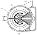
도 9와 도 10은 먼지를 압축하기 위한 제 1 가압 부재가 제 2 가압 부재의 일측에 근접한 경우의 자성 부재와 자기 감지 소자의 위치 관계를 설명하기 위한 도면이고, 도 11과 도 12는 제 1 가압 부재와 제 2 가압 부재가 일직선상에 위치하는 경우의 자성 부재와 자기 감지 소자의 위치 관계를 설명하기 위한 도면이며, 도 13과 도 14는 제 1 가압 부재가 제 2 가압 부재의 타측에 근접한 경우의 자성 부재와 자기 감지 소자의 위치 관계를 설명하기 위한 도면이다. 9 and 10 are views for explaining the positional relationship between the magnetic member and the magnetic sensing element when the first pressing member for compressing the dust is close to one side of the second pressing member, and FIGS. FIG. 13 and FIG. 14 are views for explaining the positional relationship between the magnetic member and the magnetic sensing element when the pressing member and the second pressing member are in a straight line. FIGS. 13 and 14 show that the first pressing member is close to the other side of the second pressing member. It is a figure for demonstrating the positional relationship of a magnetic member and a magnetic sensing element in a case.
도 9 내지 도 14에서 알 수 있듯이, 본 발명에서는 제 1 가압 부재(270)가 제 2 가압 부재(280)를 기준으로 대략 180도 회전하여 일직선 상에 위치하는 경우, 상기 자성 부재(415)가 상기 자기 감지 소자(440)의 수직 상방에 위치하게 되어 상기 자기 감지 소자(440)는 상기 자성 부재(415)의 자기를 감지하게 된다. 9 to 14, in the present invention, when the first pressing
여기서, 상기 자기 감지 소자(440)가 상기 자성 부재(415)의 자기를 감지하는 상태가 되는 도 11에 도시된 제 1 가압 부재(270)의 위치를 설명의 편의상 기준 위치라고 한다. Here, the position of the first pressing
그리고, 상기 제 1 가압 부재(270)가 기준 위치로부터 반시계 방향으로 회전하면서 상기 집진 바디(210) 내에 쌓인 먼지를 압축하는 동안, 상기 자성 부재(415)는 상기 자기 감지 소자(440)로부터 이격되므로, 상기 자기 감지 소자(440)에 의한 자기 감지는 이루어지지 않는다. The
그리고, 반시계 방향으로 회전하던 제 1 가압 부재(270)가 먼지의 영향으로 더 이상 회전하지 못하게 되면, 상기 제 1 가압 부재(270)는 시계 방향으로 회전하게 된다. 따라서, 상기 제 1 가압 부재(270)는 도 11에 도시된 기준 위치를 지나 도 13과 같이 제 2 가압 부재(280)의 우측으로 회전하면서 상기 집진 바디(210) 내에 쌓인 먼지를 압축하게 된다. When the first pressing
그리고, 시계 방향으로 회전하던 제 1 가압 부재(270)가 먼지의 영향으로 더 이상 회전하지 못하게 되면, 상기 압축 모터(870)는 반시계 방향으로 회전하면서 지금까지 설명한 과정을 반복 수행하면서 상기 집진 바디(210) 내에 쌓인 먼지의 압축이 수행되도록 한다. In addition, when the first pressing
도 15는 도 9 내지 도 14에서 설명한 제 1 가압 부재의 회전 동작을 총괄적으로 설명하기 위한 도면이다. FIG. 15 is a view for collectively explaining the rotation operation of the first pressing member described with reference to FIGS. 9 to 14.
도 15에는, 상기 제 1 가압 부재(270)가 기준 위치로부터 시계방향으로 회전하여 다시 기준 위치까지 복귀하기까지 소요되는 시간(TD1)과, 제 1 가압 부재(270)이 기준 위치로부터 반시계 방향으로 회전하여 다시 기준 위치까지 복귀하기까지 소요되는 시간(TD2)이 표시되어 있다. 설명의 편의상, 시간(TD1)을 제 1 왕복시간, 시간(TD2)를 제 2 왕복시간이라고 한다. 통상, 먼지는 상기 집진 바 디(210) 내부에 골고루 퍼지게 되므로 제 1 왕복시간(TD1)과 제 2 왕복시간(TD2)은 거의 동일하다고 할 수 있다. In FIG. 15, the time TD1 required for the first pressing
한편, 상기 제 1 가압 부재(270)에 의하여 압축되는 먼지의 양이 증가할수록 제 1 왕복시간(TD1)과 제 2 왕복시간(TD2)은 점점 단축된다. 본 발명에서는 상기 제 1 왕복시간(TD1)과 제 2 왕복시간(TD2) 중 어느 하나가 소정의 기준 시간이 도달하는 경우 상기 집진 바디(210) 내에 먼지가 충분히 쌓였다고 판단하여 먼지 비움 신호가 표시되도록 한다. Meanwhile, as the amount of dust compressed by the first pressing
이하에서는 본 발명에 따른 진공 청소기의 작용 및 먼지의 압축 과정에 대해서 설명한다. Hereinafter will be described the operation of the vacuum cleaner and the compression process of the dust according to the present invention.
도 16은 본 발명에 따른 진공 청소기의 제어 방법을 설명하는 흐름도이다. 16 is a flowchart illustrating a control method of the vacuum cleaner according to the present invention.
도 16을 참조하면, 사용자는 동작신호 입력부(820)에 표시되어 있는 흡입 파워인 강, 중, 약 모드 중의 하나를 선택하여 진공 청소기를 작동시킨다. 그러면, 상기 제어부(810)는 사용자가 선택한 흡입 모드에 따라 흡입 모터(850)가 구동되도록 흡입모터 드라이버(840)를 작동시킨다(S110).Referring to FIG. 16, a user selects one of strong, medium, and weak modes, which are suction powers displayed on the operation
상기 흡입 모터(850)가 작동하면 상기 흡입 모터(850)의 흡입력에 의하여 먼지가 상기 흡입 노즐을 통하여 흡입된다. 그리고, 상기 흡입 노즐을 통하여 흡입된 공기는 상기 본체 흡입부(110)를 통하여 청소기 본체(100) 내부로 유입되고, 유입된 공기는 소정의 유로를 거쳐 상기 집진 장치(200)로 유입된다.When the
상세히, 상기 먼지가 포함된 공기는 상기 집진 바디(210)의 제 1 공기 유입구(218)를 통하여 상기 제 1 싸이클론부(230)의 접선 방향으로 흡입된다. 그리고, 흡입된 공기는 상기 제 1 싸이클론부(230)의 내주면을 따라 선회하면서 낙하되고, 이 과정에서 공기와 먼지는 그 중량 차이에 의해 각기 다른 원심력을 받으면서 상호간의 분리가 이루어진다. 그리고, 먼지가 분리된 공기는 상기 필터 부재(260)의 통공(262)을 통하여 여과된 후 상기 배출공(251) 및 제 1 공기 배출구(252)를 통하여 상기 집진 장치(200)의 외부로 배출된다. In detail, the dust-containing air is sucked in the tangential direction of the
한편, 분리된 먼지는 상기 제 1 싸이클론부(230)의 내주면을 따라 선회되는 과정에서 접선 방향으로 상기 먼지 가이드 유로(232)로 유입된다. 그리고, 상기 먼지 가이드 유로(232)로 유입된 먼지는 상기 먼지 가이드 유로(232)의 내부에서 유동 방향이 절환되어 상기 제 1 싸이클론부(230)의 외주면을 따라 유동하며, 상기 배출구(234)를 통하여 하방으로 낙하되어 상기 제 1 먼지 저장부(214)에 저장된다. On the other hand, the separated dust is introduced into the dust
한편, 상기 제 1 공기 배출구(252)를 통하여 배출된 공기는 상기 청소기 본체(100) 내부로 유입된다. 그리고, 상기 청소기 본체(100) 내부로 유입된 공기는 연결 유로(114)를 지나 상기 제 2 싸이클론부(300)로 유입된다. 이러한 공기는 상기 연결 유로(114)의 끝단에 연결된 제 2 공기 유입구(미도시)를 통하여 상기 제 2 싸이클론부(300)의 내벽에 각각 접선 방향으로 안내되고, 그 내부를 유동하면서 먼지가 재차 분리된다. Meanwhile, the air discharged through the
그리고, 재차 먼지가 분리된 공기는 상기 청소기 본체(100) 내부로 유입된다. 그리고, 상기 청소기 본체(100) 내부로 유입된 공기는 흡입 모터를 지나 상기 청소기 본체(100) 후측의 본체 배출부(미도시)를 통하여 외부로 배출된다. In addition, the air from which the dust is separated again flows into the
반면, 분리된 먼지는 상기 먼지 유입구(254)를 통하여 상기 집진 장치(200) 로 유입되고, 최종적으로 상기 제 2 먼지 저장부(216)에 저장된다. On the other hand, the separated dust is introduced into the
이와 같이 공기 중의 먼지가 분리되어 상기 먼지 저장부에 먼지가 저장되는 과정에서, 상기 한 쌍의 가압 부재(270, 280)는 상기 제 1 먼지 저장부(214)에 저장된 먼지가 압축되도록 한다. 즉, 상기 제어부(810)는 상기 집진 바디(210)에 저장된 먼지를 압축시키기 위하여 압축모터(870)를 구동시킨다(S120).As the dust in the air is separated and dust is stored in the dust storage unit as described above, the pair of pressing
여기서, 본 발명에서는 상기 흡입 모터(850)의 구동 후에 압축 모터(870)를 구동하는 방식을 취하였으나, 다른 실시예로서 상기 흡입 모터(850)와 상기 압축 모터(870)를 동시에 작동시킬 수도 있을 것이다. Here, in the present invention, although the
단계(S120)에서, 상기 압축 모터(870)가 구동되면, 상기 압축 모터(870)의 회전축과 축결합되어 있는 상기 구동 기어(420)가 회전된다. 그리고, 상기 구동 기어(420)가 회전되면 이에 연동되어 상기 종동 기어(410)가 회전된다. 그리고, 상기 종동 기어(410)가 회전되면 상기 종동 기어(410)과 체결되어 있는 상기 제 1 가압 부재(270)가 자동적으로 상기 제 2 가압 부재(280) 쪽으로 회전되면서 먼지를 압축하게 된다. In operation S120, when the
이 때, 상기 제어부(810)는 상기 제 1 가압 부재(270)가 기준 위치에 위치하는지 여부를 우선 확인한다(S130). 본 발명은 제 1 가압 부재(270)의 기준 위치를 기준으로 하여 제 1 및 제 2 왕복시간을 측정하는 것이므로, 최초 동작시, 상기 제 1 가압 부재(270)가 기준 위치에 있다는 것을 확인할 필요가 있다. 상기 제 1 가압부재(270)가 기준 위치에 위치한다는 것은 최초 동작시 상기 자기 감지 소자(440)가 상기 자성 부재(415)의 자기를 처음으로 감지하게 되는 시점일 것이다. At this time, the
따라서, 상기 제어부(810)는 상기 자기 감지 소자(440)가 처음으로 자기를 감지하는 시점을 기준으로하여 제 1 왕복시간 또는 제 2 왕복시간을 측정하게 된다. 그리고, 상기 제 1 가압 부재(270)가 기준 위치로 이동한 시점을 시작으로 상기 제어부(810)는 제 1 가압 부재(270)의 시계 방향으로의 이동 또는 반시계 방향으로 이동에 따라서, 제 1 왕복시간(TD1)과 제 2 왕복시간(TD2)을 측정한다(S140). Therefore, the
여기서, 상기 제 1 가압 부재(270)와 상기 제 2 가압 부재(280)에 의하여 집진 바디(210) 내부에서 압축되는 먼지의 양이 증가할수록 상기 종동 기어(410)의 좌우 왕복 회전 시간이 짧아진다. Here, as the amount of dust compressed in the
상기 제어부(810)는 상기 자기 감지 소자(440)를 통하여 상기 제 1 가압 부재(270)의 제 1 왕복시간(TD1)과 제 2 왕복시간(TD2)을 측정하면서, 상기 제 1 왕복시간(TD1) 또는 제 2 왕복시간(TD2)이 소정의 기준 시간에 도달하였는지 여부를 판단한다(S150). 여기서, 소정의 기준 시간은 설계자에 의하여 제어부(810) 자체에 설정한 시간으로서, 이는 상기 집진 바디(210) 내에 먼지가 일정량 이상 쌓였다고 판단하는 근거가 된다. 상기 기준 시간은 설계자가 다수회 반복 실험하여 얻어지는 것으로써 진공 청소기의 용량에 따라 달라진다. The
본 발명의 경우, 제 1 왕복시간(TD1) 또는 제 2 왕복시간(TD2) 중 어느 하나가 기준 시간에 도달하는 경우, 먼지의 양이 소정량에 도달하였다고 판단하는 방식을 취하였으나, 다른 실시예로서, 그 판단 근거를 제 1 왕복시간(TD1)과 제 2 왕복시간(TD2)이 모두 소정의 기준 시간 이내에 도달한 경우로 할 수도 있을 것이다. In the case of the present invention, when either the first round trip time (TD1) or the second round trip time (TD2) reaches the reference time, it took a way to determine that the amount of dust has reached a predetermined amount, another embodiment The reason for the determination may be the case where both the first round trip time TD1 and the second round trip time TD2 have reached within a predetermined reference time.
단계(S150)에서의 판단 결과, 제 1 왕복시간(TD1)과 제 2 왕복시간(TD2) 중 의 어느 하나라도 기준 시간보다 긴 경우에는 단계(S140)으로 복귀하여 이전의 과정을 수행한다. 이에 반하여 제 1 왕복시간(TD1) 또는 제 2 왕복시간(TD2)이 기준 시간에 도달한 경우, 상기 제어부(810)는 상기 흡입 모터(850)를 오프시켜 먼지가 더이상 흡입되지 않도록 한다(S160). 여기서, 상기 흡입 모터(850)를 강제적으로 정지시키는 이유는 상기 집진 바디(210) 내부에 쌓인 먼지의 양이 소정 양을 초과한 경우에 강제적으로 먼지 흡입 동작을 계속하게 되면 먼지 흡입 효율이 떨어질 뿐만 아니라 흡입 모터(850)에도 과부하가 걸릴 수 있기 때문이다. 이 때, 상기 압축 모터(870)도 함께 오프되도록 제어하는것이 바람직할 것이다. As a result of the determination in step S150, when any one of the first round trip time TD1 and the second round trip time TD2 is longer than the reference time, the process returns to step S140 to perform the previous process. On the contrary, when the first round trip time TD1 or the second round trip time TD2 reaches the reference time, the
다음, 상기 제어부(810)는 집진 바디(210) 내의 먼지를 비우라는 신호를 먼지교환신호 표시부(830)로 전송하여 사용자가 인식할 수 있도록 한다. 본 발명의 다른 실시예로서, 먼지교환신호는 부저 회로를 이용하여 소정의 소리 신호로 표시할 수도 있을 것이다. Next, the
본 발명의 경우, 집진 장치(200)의 먼지 비움 시기가 사용자에게 알려짐에 따라 사용자의 편의성이 증대되고, 이렇게 먼지 비움 알림 기능이 수행되는 과정에서 흡입 모터의 작동이 조절되도록 함으로써, 과도한 먼지의 흡입에 따른 상기 청소기의 작동 성능이 저하되는 것이 방지된다. In the present invention, the user's convenience is increased as the dust emptying time of the
한편, 지금까지 설명한 본 발명의 기술적 사상은 업라이트 형의 청소기나 로봇 청소기에도 적용할 수 있음은 물론이다. On the other hand, the technical idea of the present invention described so far can be applied to an upright cleaner or a robot cleaner, of course.
제안되는 바와 같은 본 발명에 의하면 다음과 같은 효과가 있다. According to the present invention as proposed has the following effects.
첫째, 본 발명에 따른 진공 청소기에 의하면, 집진 장치 내부에 저장되는 먼지가 압축되어 그 부피가 최소화되므로, 상기 집진 장치 내부에 저장되는 먼지의 집진 용량이 최대화되는 효과가 있다. First, according to the vacuum cleaner according to the present invention, since the dust stored in the dust collecting apparatus is compressed to minimize its volume, the dust collecting capacity of the dust stored in the dust collecting apparatus is maximized.
둘째, 먼지의 압축 작용에 의해서 상기 집진 장치의 집진 용량이 최대화됨에 따라 사용자가 상기 집진 장치의 내부에 저장된 먼지를 자주 비워줘야 하는 번거로움이 제거되는 효과가 있다. Second, as the dust collecting capacity of the dust collecting device is maximized by the compression action of the dust, the user has to remove the trouble of frequently emptying the dust stored in the dust collecting device.
셋째, 진공 청소기의 작동이 정지된 경우에도 집진 장치 내부에 집진된 먼지가 압축된 상태를 유지함에 따라, 먼지의 비움시 상기 집진 장치 내부에 저장된 먼지가 상기 집진 장치 외부로 쉽게 배출되게 된다. Third, even when the operation of the vacuum cleaner is stopped, the dust collected in the dust collector is kept compressed, so that the dust stored in the dust collector is easily discharged to the outside of the dust collector when the dust is empty.
넷째, 집진 장치 내부에 소정량 이상의 먼지가 집진되면, 상기 집진 장치의 먼지 비움 시기가 표시되어 사용자가 먼지를 비우는 시기를 쉽게 알 수 있는 효과가 있다. Fourth, when a predetermined amount or more of dust is collected in the dust collecting apparatus, the dust emptying timing of the dust collecting apparatus is displayed, so that the user can easily know when to empty the dust.
Claims (6)
Priority Applications (6)
| Application Number | Priority Date | Filing Date | Title |
|---|---|---|---|
| KR1020070015806A KR100800189B1 (en) | 2007-02-15 | 2007-02-15 | Vacuum cleaner |
| PCT/KR2007/005758 WO2008100005A1 (en) | 2007-02-15 | 2007-11-15 | Vacuum cleaner |
| EP07834064.3A EP2120667B1 (en) | 2007-02-15 | 2007-11-15 | Vacuum cleaner |
| RU2009131043/12A RU2413451C1 (en) | 2007-02-15 | 2007-11-15 | Vacuum cleaner |
| AU2007346911A AU2007346911B2 (en) | 2007-02-15 | 2007-11-15 | Vacuum cleaner |
| US12/407,964 US8012250B2 (en) | 2005-12-10 | 2009-03-20 | Vacuum cleaner |
Applications Claiming Priority (1)
| Application Number | Priority Date | Filing Date | Title |
|---|---|---|---|
| KR1020070015806A KR100800189B1 (en) | 2007-02-15 | 2007-02-15 | Vacuum cleaner |
Publications (1)
| Publication Number | Publication Date |
|---|---|
| KR100800189B1 true KR100800189B1 (en) | 2008-02-01 |
Family
ID=39342083
Family Applications (1)
| Application Number | Title | Priority Date | Filing Date |
|---|---|---|---|
| KR1020070015806A Expired - Fee Related KR100800189B1 (en) | 2005-12-10 | 2007-02-15 | Vacuum cleaner |
Country Status (1)
| Country | Link |
|---|---|
| KR (1) | KR100800189B1 (en) |
Cited By (17)
| Publication number | Priority date | Publication date | Assignee | Title |
|---|---|---|---|---|
| WO2009104878A3 (en) * | 2008-02-19 | 2009-10-29 | Lg Electronics Inc. | Vacuum cleaner and dust separation apparatus thereof |
| WO2010002098A1 (en) * | 2008-07-02 | 2010-01-07 | 엘지전자 주식회사 | Vacuum cleaner |
| US7749295B2 (en) | 2005-12-10 | 2010-07-06 | Lg Electronics Inc. | Vacuum cleaner with removable dust collector, and methods of operating the same |
| US7770253B2 (en) | 2005-12-10 | 2010-08-10 | Lg Electronics Inc. | Vacuum cleaner with removable dust collector, and methods of operating the same |
| US7785396B2 (en) | 2005-12-10 | 2010-08-31 | Lg Electronics Inc. | Vacuum cleaner with removable dust collector, and methods of operating the same |
| KR100992221B1 (en) | 2008-05-16 | 2010-11-05 | 엘지전자 주식회사 | Vacuum cleaner |
| KR101010416B1 (en) * | 2008-07-08 | 2011-01-21 | 엘지전자 주식회사 | Vacuum cleaner |
| US7987551B2 (en) | 2005-12-10 | 2011-08-02 | Lg Electronics Inc. | Vacuum cleaner |
| US7992253B2 (en) | 2007-01-24 | 2011-08-09 | Lg Electronics Inc. | Vacuum cleaner |
| US7992252B2 (en) | 2009-02-12 | 2011-08-09 | Lg Electronics Inc. | Vacuum cleaner |
| US8012250B2 (en) | 2005-12-10 | 2011-09-06 | Lg Electronics Inc. | Vacuum cleaner |
| US8151409B2 (en) | 2009-02-26 | 2012-04-10 | Lg Electronics Inc. | Vacuum cleaner |
| CN102525342A (en) * | 2010-12-15 | 2012-07-04 | 乐金电子(天津)电器有限公司 | Magnetic clutch structure for manual compression of dust-collecting cylinder |
| CN103126614A (en) * | 2011-12-02 | 2013-06-05 | 乐金电子(天津)电器有限公司 | Dust collector dust collecting device provided with dust fullness display device and dust fullness display method |
| US8544143B2 (en) | 2005-12-10 | 2013-10-01 | Lg Electronics Inc. | Vacuum cleaner with removable dust collector, and methods of operating the same |
| US8713752B2 (en) | 2009-03-13 | 2014-05-06 | Lg Electronics Inc. | Vacuum cleaner |
| US8978197B2 (en) | 2009-03-13 | 2015-03-17 | Lg Electronics Inc. | Vacuum cleaner |
Citations (6)
| Publication number | Priority date | Publication date | Assignee | Title |
|---|---|---|---|---|
| KR950016642A (en) * | 1993-12-03 | 1995-07-20 | 이헌조 | Dust bag crimping device of vacuum cleaner |
| KR20010090527A (en) * | 2000-03-24 | 2001-10-18 | 마찌다 가쯔히꼬 | Electric vacuum cleaner |
| KR20060031442A (en) * | 2004-10-08 | 2006-04-12 | 엘지전자 주식회사 | Cyclone dust collector |
| JP2007095001A (en) * | 2005-09-30 | 2007-04-12 | Noritsu Koki Co Ltd | Print processing system |
| JP2008001009A (en) * | 2006-06-23 | 2008-01-10 | Zebra Pen Corp | Written part connection structure |
| JP2008006003A (en) * | 2006-06-28 | 2008-01-17 | Tiger Vacuum Bottle Co Ltd | Attachment for chopper function of cooking mixer |
-
2007
- 2007-02-15 KR KR1020070015806A patent/KR100800189B1/en not_active Expired - Fee Related
Patent Citations (6)
| Publication number | Priority date | Publication date | Assignee | Title |
|---|---|---|---|---|
| KR950016642A (en) * | 1993-12-03 | 1995-07-20 | 이헌조 | Dust bag crimping device of vacuum cleaner |
| KR20010090527A (en) * | 2000-03-24 | 2001-10-18 | 마찌다 가쯔히꼬 | Electric vacuum cleaner |
| KR20060031442A (en) * | 2004-10-08 | 2006-04-12 | 엘지전자 주식회사 | Cyclone dust collector |
| JP2007095001A (en) * | 2005-09-30 | 2007-04-12 | Noritsu Koki Co Ltd | Print processing system |
| JP2008001009A (en) * | 2006-06-23 | 2008-01-10 | Zebra Pen Corp | Written part connection structure |
| JP2008006003A (en) * | 2006-06-28 | 2008-01-17 | Tiger Vacuum Bottle Co Ltd | Attachment for chopper function of cooking mixer |
Non-Patent Citations (3)
| Title |
|---|
| 한국공개특허공보 특19950016642호 |
| 한국공개특허공보 특2001-0090527호 |
| 한국공개특허공보 특2006-0031442호 |
Cited By (32)
| Publication number | Priority date | Publication date | Assignee | Title |
|---|---|---|---|---|
| US8043397B2 (en) | 2005-12-10 | 2011-10-25 | Lg Electronics Inc. | Vacuum cleaner with removable dust collector, and methods of operating the same |
| US8012250B2 (en) | 2005-12-10 | 2011-09-06 | Lg Electronics Inc. | Vacuum cleaner |
| US8240001B2 (en) | 2005-12-10 | 2012-08-14 | Lg Electronics Inc. | Vacuum cleaner with removable dust collector, and methods of operating the same |
| US7749295B2 (en) | 2005-12-10 | 2010-07-06 | Lg Electronics Inc. | Vacuum cleaner with removable dust collector, and methods of operating the same |
| US7770253B2 (en) | 2005-12-10 | 2010-08-10 | Lg Electronics Inc. | Vacuum cleaner with removable dust collector, and methods of operating the same |
| US7785396B2 (en) | 2005-12-10 | 2010-08-31 | Lg Electronics Inc. | Vacuum cleaner with removable dust collector, and methods of operating the same |
| US8544143B2 (en) | 2005-12-10 | 2013-10-01 | Lg Electronics Inc. | Vacuum cleaner with removable dust collector, and methods of operating the same |
| US7998234B2 (en) | 2005-12-10 | 2011-08-16 | Lg Electronics Inc. | Vacuum cleaner with removable dust collector, and methods of operating the same |
| US8060979B2 (en) | 2005-12-10 | 2011-11-22 | Lg Electronics Inc. | Vacuum cleaner with removable dust collector, and methods of operating the same |
| US7987551B2 (en) | 2005-12-10 | 2011-08-02 | Lg Electronics Inc. | Vacuum cleaner |
| US8043410B2 (en) | 2005-12-10 | 2011-10-25 | Lg Electronics Inc. | Vacuum cleaner with removable dust collector, and methods of operating the same |
| US8021452B2 (en) | 2005-12-10 | 2011-09-20 | Lg Electronics Inc. | Vacuum cleaner with removable dust collector, and methods of operating the same |
| US7992253B2 (en) | 2007-01-24 | 2011-08-09 | Lg Electronics Inc. | Vacuum cleaner |
| WO2009104878A3 (en) * | 2008-02-19 | 2009-10-29 | Lg Electronics Inc. | Vacuum cleaner and dust separation apparatus thereof |
| RU2437610C1 (en) * | 2008-02-19 | 2011-12-27 | ЭлДжи ЭЛЕКТРОНИКС ИНК. | Vacuum cleaner and device for dust separation |
| US8544144B2 (en) | 2008-02-19 | 2013-10-01 | Lg Electronics Inc. | Vacuum cleaner and dust separation apparatus thereof |
| KR100941429B1 (en) * | 2008-02-19 | 2010-02-11 | 엘지전자 주식회사 | Vacuum cleaner |
| KR100992221B1 (en) | 2008-05-16 | 2010-11-05 | 엘지전자 주식회사 | Vacuum cleaner |
| KR100996531B1 (en) * | 2008-07-02 | 2010-11-24 | 엘지전자 주식회사 | Vacuum cleaner |
| EP2322070A4 (en) * | 2008-07-02 | 2012-08-22 | Lg Electronics Inc | Vacuum cleaner |
| WO2010002098A1 (en) * | 2008-07-02 | 2010-01-07 | 엘지전자 주식회사 | Vacuum cleaner |
| US8584313B2 (en) | 2008-07-02 | 2013-11-19 | Lg Electronics Inc. | Vacuum cleaner |
| RU2458621C1 (en) * | 2008-07-02 | 2012-08-20 | ЭлДжи ЭЛЕКТРОНИКС ИНК. | Vacuum cleaner |
| KR101010416B1 (en) * | 2008-07-08 | 2011-01-21 | 엘지전자 주식회사 | Vacuum cleaner |
| US8528163B2 (en) | 2009-02-12 | 2013-09-10 | Lg Electronics Inc. | Vacuum cleaner |
| US7992252B2 (en) | 2009-02-12 | 2011-08-09 | Lg Electronics Inc. | Vacuum cleaner |
| US8881343B2 (en) | 2009-02-12 | 2014-11-11 | Lg Electronics Inc. | Vacuum cleaner |
| US8151409B2 (en) | 2009-02-26 | 2012-04-10 | Lg Electronics Inc. | Vacuum cleaner |
| US8713752B2 (en) | 2009-03-13 | 2014-05-06 | Lg Electronics Inc. | Vacuum cleaner |
| US8978197B2 (en) | 2009-03-13 | 2015-03-17 | Lg Electronics Inc. | Vacuum cleaner |
| CN102525342A (en) * | 2010-12-15 | 2012-07-04 | 乐金电子(天津)电器有限公司 | Magnetic clutch structure for manual compression of dust-collecting cylinder |
| CN103126614A (en) * | 2011-12-02 | 2013-06-05 | 乐金电子(天津)电器有限公司 | Dust collector dust collecting device provided with dust fullness display device and dust fullness display method |
Similar Documents
| Publication | Publication Date | Title |
|---|---|---|
| KR100800189B1 (en) | Vacuum cleaner | |
| KR100838886B1 (en) | Vacuum cleaner | |
| AU2008200340B2 (en) | Vacuum cleaner | |
| KR100996531B1 (en) | Vacuum cleaner | |
| KR100838887B1 (en) | Vacuum cleaner | |
| KR100853332B1 (en) | Vacuum cleaner, dust separation device of vacuum cleaner and control method of vacuum cleaner | |
| KR100876694B1 (en) | How to control the vacuum cleaner | |
| KR100912316B1 (en) | Vacuum cleaner | |
| KR100809773B1 (en) | Vacuum cleaner control method | |
| KR100947361B1 (en) | Vacuum cleaner | |
| KR100871487B1 (en) | How to control the vacuum cleaner | |
| KR100925145B1 (en) | Vacuum cleaner | |
| KR100906848B1 (en) | Vacuum cleaner | |
| KR100947360B1 (en) | Vacuum cleaner and its control method | |
| KR100937146B1 (en) | Vacuum cleaner and control method thereof | |
| KR100842964B1 (en) | Vacuum cleaner | |
| KR100880495B1 (en) | Vacuum cleaner | |
| KR20100039981A (en) | Vacuum cleaner | |
| KR100813723B1 (en) | Vacuum cleaner and its control method | |
| KR101052107B1 (en) | Vacuum cleaner | |
| KR100895145B1 (en) | How to control the vacuum cleaner | |
| KR101093941B1 (en) | Vacuum cleaner | |
| KR100876699B1 (en) | Vacuum cleaner | |
| KR100838888B1 (en) | Vacuum cleaner | |
| KR100906849B1 (en) | Vacuum cleaner and its control method |
Legal Events
| Date | Code | Title | Description |
|---|---|---|---|
| A201 | Request for examination | ||
| PA0109 | Patent application |
St.27 status event code: A-0-1-A10-A12-nap-PA0109 |
|
| PA0201 | Request for examination |
St.27 status event code: A-1-2-D10-D11-exm-PA0201 |
|
| E701 | Decision to grant or registration of patent right | ||
| PE0701 | Decision of registration |
St.27 status event code: A-1-2-D10-D22-exm-PE0701 |
|
| GRNT | Written decision to grant | ||
| PR0701 | Registration of establishment |
St.27 status event code: A-2-4-F10-F11-exm-PR0701 |
|
| PR1002 | Payment of registration fee |
St.27 status event code: A-2-2-U10-U11-oth-PR1002 Fee payment year number: 1 |
|
| PG1601 | Publication of registration |
St.27 status event code: A-4-4-Q10-Q13-nap-PG1601 |
|
| PN2301 | Change of applicant |
St.27 status event code: A-5-5-R10-R13-asn-PN2301 St.27 status event code: A-5-5-R10-R11-asn-PN2301 |
|
| R18-X000 | Changes to party contact information recorded |
St.27 status event code: A-5-5-R10-R18-oth-X000 |
|
| R18-X000 | Changes to party contact information recorded |
St.27 status event code: A-5-5-R10-R18-oth-X000 |
|
| PR1001 | Payment of annual fee |
St.27 status event code: A-4-4-U10-U11-oth-PR1001 Fee payment year number: 4 |
|
| PR1001 | Payment of annual fee |
St.27 status event code: A-4-4-U10-U11-oth-PR1001 Fee payment year number: 5 |
|
| FPAY | Annual fee payment |
Payment date: 20121227 Year of fee payment: 6 |
|
| PR1001 | Payment of annual fee |
St.27 status event code: A-4-4-U10-U11-oth-PR1001 Fee payment year number: 6 |
|
| FPAY | Annual fee payment |
Payment date: 20131224 Year of fee payment: 7 |
|
| PR1001 | Payment of annual fee |
St.27 status event code: A-4-4-U10-U11-oth-PR1001 Fee payment year number: 7 |
|
| FPAY | Annual fee payment |
Payment date: 20141224 Year of fee payment: 8 |
|
| PR1001 | Payment of annual fee |
St.27 status event code: A-4-4-U10-U11-oth-PR1001 Fee payment year number: 8 |
|
| PN2301 | Change of applicant |
St.27 status event code: A-5-5-R10-R13-asn-PN2301 St.27 status event code: A-5-5-R10-R11-asn-PN2301 |
|
| FPAY | Annual fee payment |
Payment date: 20151224 Year of fee payment: 9 |
|
| PR1001 | Payment of annual fee |
St.27 status event code: A-4-4-U10-U11-oth-PR1001 Fee payment year number: 9 |
|
| FPAY | Annual fee payment |
Payment date: 20161214 Year of fee payment: 10 |
|
| PR1001 | Payment of annual fee |
St.27 status event code: A-4-4-U10-U11-oth-PR1001 Fee payment year number: 10 |
|
| P22-X000 | Classification modified |
St.27 status event code: A-4-4-P10-P22-nap-X000 |
|
| FPAY | Annual fee payment |
Payment date: 20171214 Year of fee payment: 11 |
|
| PR1001 | Payment of annual fee |
St.27 status event code: A-4-4-U10-U11-oth-PR1001 Fee payment year number: 11 |
|
| PR1001 | Payment of annual fee |
St.27 status event code: A-4-4-U10-U11-oth-PR1001 Fee payment year number: 12 |
|
| PR1001 | Payment of annual fee |
St.27 status event code: A-4-4-U10-U11-oth-PR1001 Fee payment year number: 13 |
|
| PN2301 | Change of applicant |
St.27 status event code: A-5-5-R10-R13-asn-PN2301 St.27 status event code: A-5-5-R10-R11-asn-PN2301 |
|
| PC1903 | Unpaid annual fee |
St.27 status event code: A-4-4-U10-U13-oth-PC1903 Not in force date: 20210126 Payment event data comment text: Termination Category : DEFAULT_OF_REGISTRATION_FEE |
|
| PC1903 | Unpaid annual fee |
St.27 status event code: N-4-6-H10-H13-oth-PC1903 Ip right cessation event data comment text: Termination Category : DEFAULT_OF_REGISTRATION_FEE Not in force date: 20210126 |