JPWO2008007521A1 - Reticle holding member, reticle stage, exposure apparatus, projection exposure method, and device manufacturing method - Google Patents
Reticle holding member, reticle stage, exposure apparatus, projection exposure method, and device manufacturing method Download PDFInfo
- Publication number
- JPWO2008007521A1 JPWO2008007521A1 JP2008524743A JP2008524743A JPWO2008007521A1 JP WO2008007521 A1 JPWO2008007521 A1 JP WO2008007521A1 JP 2008524743 A JP2008524743 A JP 2008524743A JP 2008524743 A JP2008524743 A JP 2008524743A JP WO2008007521 A1 JPWO2008007521 A1 JP WO2008007521A1
- Authority
- JP
- Japan
- Prior art keywords
- reticle
- holding member
- stage
- reticle holding
- member according
- Prior art date
- Legal status (The legal status is an assumption and is not a legal conclusion. Google has not performed a legal analysis and makes no representation as to the accuracy of the status listed.)
- Pending
Links
Images
Classifications
-
- G—PHYSICS
- G03—PHOTOGRAPHY; CINEMATOGRAPHY; ANALOGOUS TECHNIQUES USING WAVES OTHER THAN OPTICAL WAVES; ELECTROGRAPHY; HOLOGRAPHY
- G03F—PHOTOMECHANICAL PRODUCTION OF TEXTURED OR PATTERNED SURFACES, e.g. FOR PRINTING, FOR PROCESSING OF SEMICONDUCTOR DEVICES; MATERIALS THEREFOR; ORIGINALS THEREFOR; APPARATUS SPECIALLY ADAPTED THEREFOR
- G03F7/00—Photomechanical, e.g. photolithographic, production of textured or patterned surfaces, e.g. printing surfaces; Materials therefor, e.g. comprising photoresists; Apparatus specially adapted therefor
- G03F7/70—Microphotolithographic exposure; Apparatus therefor
- G03F7/70691—Handling of masks or workpieces
- G03F7/70733—Handling masks and workpieces, e.g. exchange of workpiece or mask, transport of workpiece or mask
- G03F7/70741—Handling masks outside exposure position, e.g. reticle libraries
-
- G—PHYSICS
- G03—PHOTOGRAPHY; CINEMATOGRAPHY; ANALOGOUS TECHNIQUES USING WAVES OTHER THAN OPTICAL WAVES; ELECTROGRAPHY; HOLOGRAPHY
- G03F—PHOTOMECHANICAL PRODUCTION OF TEXTURED OR PATTERNED SURFACES, e.g. FOR PRINTING, FOR PROCESSING OF SEMICONDUCTOR DEVICES; MATERIALS THEREFOR; ORIGINALS THEREFOR; APPARATUS SPECIALLY ADAPTED THEREFOR
- G03F7/00—Photomechanical, e.g. photolithographic, production of textured or patterned surfaces, e.g. printing surfaces; Materials therefor, e.g. comprising photoresists; Apparatus specially adapted therefor
- G03F7/70—Microphotolithographic exposure; Apparatus therefor
- G03F7/70691—Handling of masks or workpieces
- G03F7/707—Chucks, e.g. chucking or un-chucking operations or structural details
-
- G—PHYSICS
- G03—PHOTOGRAPHY; CINEMATOGRAPHY; ANALOGOUS TECHNIQUES USING WAVES OTHER THAN OPTICAL WAVES; ELECTROGRAPHY; HOLOGRAPHY
- G03F—PHOTOMECHANICAL PRODUCTION OF TEXTURED OR PATTERNED SURFACES, e.g. FOR PRINTING, FOR PROCESSING OF SEMICONDUCTOR DEVICES; MATERIALS THEREFOR; ORIGINALS THEREFOR; APPARATUS SPECIALLY ADAPTED THEREFOR
- G03F7/00—Photomechanical, e.g. photolithographic, production of textured or patterned surfaces, e.g. printing surfaces; Materials therefor, e.g. comprising photoresists; Apparatus specially adapted therefor
- G03F7/70—Microphotolithographic exposure; Apparatus therefor
- G03F7/70691—Handling of masks or workpieces
- G03F7/707—Chucks, e.g. chucking or un-chucking operations or structural details
- G03F7/70708—Chucks, e.g. chucking or un-chucking operations or structural details being electrostatic; Electrostatically deformable vacuum chucks
Landscapes
- Physics & Mathematics (AREA)
- General Physics & Mathematics (AREA)
- Engineering & Computer Science (AREA)
- Library & Information Science (AREA)
- Exposure And Positioning Against Photoresist Photosensitive Materials (AREA)
- Exposure Of Semiconductors, Excluding Electron Or Ion Beam Exposure (AREA)
Abstract
停電時にもレチクルをレチクル・ステージから落下させず、また、レチクルの、パターンが形成されている面の平面度を維持することのできるレチクル保持部材を提供する。レチクル(100)を保持するレチクル保持部材(101)であって、周縁部の少なくとも一部がレチクルより突出し、突出した周縁部が、露光装置のレチクル・ステージ(201,203)によって支持されて取り付けられるように構成されたことを特徴とする。Provided is a reticle holding member capable of maintaining the flatness of a surface of a reticle on which a pattern is formed without dropping the reticle from the reticle stage even during a power failure. A reticle holding member (101) for holding the reticle (100), wherein at least a part of the peripheral edge protrudes from the reticle, and the protruded peripheral edge is supported and attached by the reticle stage (201, 203) of the exposure apparatus. It was comprised so that it might be possible.
Description
本発明は、レチクル保持部材、当該レチクル保持部材を使用するレチクル・ステージ、露光装置、投影露光方法およびデバイス製造方法に関する。特に、レチクルのパターンが形成されていない面を覆って、レチクルを保持するレチクル保持部材、当該レチクル保持部材を使用するレチクル・ステージ、露光装置、投影露光方法およびデバイス製造方法に関する。 The present invention relates to a reticle holding member, a reticle stage using the reticle holding member, an exposure apparatus, a projection exposure method, and a device manufacturing method. In particular, the present invention relates to a reticle holding member that holds a reticle so as to cover a surface on which a reticle pattern is not formed, a reticle stage that uses the reticle holding member, an exposure apparatus, a projection exposure method, and a device manufacturing method.
近年、半導体集積回路の微細化に伴い、光の回折限界によって制限される光学系の解像力を向上させるために、従来の紫外線に代えてこれより短い波長(11乃至14nm、より広義には5乃至50nm)のEUV(Extreme Ultraviolet)光を使用した投影リソグラフィ技術が開発されている。この技術は、最近ではEUV(Extreme Ultraviolet)リソグラフィと呼ばれており、従来の波長190nm程度の光線を用いた光リソグラフィでは実現不可能な、70nm以下の解像力を得られる技術として期待されている。 In recent years, with the miniaturization of semiconductor integrated circuits, in order to improve the resolution of an optical system limited by the diffraction limit of light, a shorter wavelength (11 to 14 nm, more broadly 5 to A projection lithography technique using EUV (Extreme Ultraviolet) light of 50 nm) has been developed. This technique is recently called EUV (Extreme Ultraviolet) lithography, and is expected as a technique that can obtain a resolution of 70 nm or less, which is impossible to achieve with conventional optical lithography using light having a wavelength of about 190 nm.
EUV光の波長領域での物質の複素屈折率nは、n=1−δ−ik(iは複素記号)で表わされる。この屈折率の虚部kは極端紫外線の吸収を表す。δ、kは1に比べて非常に小さいため、この領域での屈折率は1に非常に近い。したがって従来のレンズのような透過屈折型の光学素子を使用できず、反射を利用した光学系が使用される。 A complex refractive index n of a substance in a wavelength region of EUV light is represented by n = 1−δ−ik (i is a complex symbol). The imaginary part k of the refractive index represents absorption of extreme ultraviolet rays. Since δ and k are much smaller than 1, the refractive index in this region is very close to 1. Accordingly, a transmission / refraction type optical element such as a conventional lens cannot be used, and an optical system utilizing reflection is used.
また、レチクル(マスクとも呼ばれる)も従来の透過型のレチクルではなく、反射型のレチクルが使用される。 In addition, a reticle (also called a mask) is not a conventional transmission type reticle but a reflection type reticle.
レチクルの搬送時などに、レチクルのパターンが形成された面を保護するために、当該面を保護するカバーが取り付けられることもある(たとえば、米国特許US6239863B1)。 In order to protect the surface on which the reticle pattern is formed when the reticle is transported, a cover for protecting the surface may be attached (for example, US Pat. No. 6,623,986 B1).
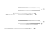
図9は、従来の方法によって、搬送アーム301によってレチクル・ステージ201aに搬送されるレチクル100およびレチクル・ステージ201aに取り付けられたレチクル100を示す図である。レチクル・ステージ201aは、静電チャックを備え、レチクル100を吸着する。
FIG. 9 is a diagram showing the
従来においては、停電などによって露光装置に電力が供給されなくなると、静電チャックの吸着力が低下し、最悪の場合は、レチクルが落下してしまう。 Conventionally, when power is not supplied to the exposure apparatus due to a power failure or the like, the chucking force of the electrostatic chuck is reduced, and in the worst case, the reticle is dropped.
停電時にもレチクルをレチクル・ステージから落下させないチクル保持部材、当該レチクル保持部材を使用するレチクル・ステージ、露光装置および露光方法に対するニーズがある。 There is a need for a reticle holding member that does not drop the reticle from the reticle stage even during a power failure, a reticle stage that uses the reticle holding member, an exposure apparatus, and an exposure method.
一実施形態によるレチクル保持部材は、レチクルのパターンが形成されていない面に配置され、レチクルを保持するレチクル保持部材であって、周縁部の少なくとも一部がレチクルより突出し、突出した周縁部が、露光装置のレチクル・ステージによって支持されて取り付けられるように構成されている。 A reticle holding member according to an embodiment is a reticle holding member that is disposed on a surface on which a reticle pattern is not formed and holds a reticle, wherein at least a part of the peripheral edge protrudes from the reticle, and the protruding peripheral edge is It is configured to be supported and attached by the reticle stage of the exposure apparatus.
他の実施形態によるレチクル保持部材によれば、静電チャックのみによってレチクルをレチクル・ステージに保持するのではなく、レチクル保持部材の突出した周縁部が、露光装置のレチクル・ステージによって支持されて取り付けられるように構成されているので、停電時にもレチクルをレチクル・ステージから落下させることはない。 According to the reticle holding member according to another embodiment, instead of holding the reticle on the reticle stage only by the electrostatic chuck, the protruding peripheral edge portion of the reticle holding member is supported and attached by the reticle stage of the exposure apparatus. The reticle is not dropped from the reticle stage even during a power failure.
レチクルをレチクル・ステージの静電チャックから取り外している間に、レチクルの静電チャックに吸着される面に異物が付着し、つぎに、レチクルを静電チャックに吸着させる場合に、レチクルと静電チャックとの間に当該異物が挟み込まれてしまう可能性がある。この結果、レチクルの、パターンが形成されている面の平面度が悪化し、レチクルを使用した投影露光装置の解像度やパターン位置精度等が低下する可能性がある。 While removing the reticle from the electrostatic chuck of the reticle stage, foreign matter adheres to the surface of the reticle that is attracted to the electrostatic chuck, and then when the reticle is attracted to the electrostatic chuck, There is a possibility that the foreign matter is sandwiched between the chuck and the chuck. As a result, the flatness of the surface of the reticle on which the pattern is formed deteriorates, and there is a possibility that the resolution, pattern position accuracy, etc. of the projection exposure apparatus using the reticle will be reduced.
レチクルを直接レチクル・ステージに取り付けないことによって、例え、レチクルのパターンが形成されていない面にゴミが付着したとしても、レチクルの、パターンが形成されている面の平面度を維持することができる。 By not attaching the reticle directly to the reticle stage, even if dust adheres to the surface on which the reticle pattern is not formed, the flatness of the surface on which the reticle is formed can be maintained. .
実施形態によれば、停電時にもレチクルをレチクル・ステージから落下させないレチクル保持部材、当該レチクル保持部材を使用するレチクル・ステージ、露光装置および露光方法が得られる。 According to the embodiment, a reticle holding member that does not drop the reticle from the reticle stage even when a power failure occurs, a reticle stage that uses the reticle holding member, an exposure apparatus, and an exposure method are obtained.
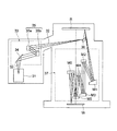
図8は、EUV露光装置の構成を示す図である。 FIG. 8 is a diagram showing the configuration of the EUV exposure apparatus.
EUV光源31から放出されたEUV光32は、照明光学系33に入射し、コリメータミラーとして作用する凹面反射鏡34を介してほぼ平行光束となり、一対のフライアイミラー35aおよび35bからなるオプティカルインテグレータ35に入射する。
The EUV
フライアイミラー35aの反射面の近傍、すなわちオプティカルインテグレータ35の射出面の近傍には、所定の形状を有する実質的な面光源が形成される。実質的な面光源からの光は、平面反射鏡36により偏向された後、レチクルR上に細長い円弧状の照明領域を形成する(円弧状の照明領域を形成するための開口板は図示を省略している)。照明されたレチクルRのパターンからの光は、複数の反射鏡(図8では例示的に6つの反射鏡M1〜M6)からなる投影光学系37を介して、ウエハW上にレチクルパターンの像を形成する。なお、レチクルRはレチクル・ステージ、ウエハWはウエハ・ステージに保持され、レチクルR面のパターン像をウエハWに転写する。ここでは、レチクル・ステージ、ウエハ・ステージの図示を省略している。
A substantial surface light source having a predetermined shape is formed in the vicinity of the reflective surface of the fly-
EUV光は、空気によっても吸収されるため、露光装置の鏡筒内は高度の真空に保つ必要がある。 Since EUV light is also absorbed by air, it is necessary to maintain a high vacuum in the lens barrel of the exposure apparatus.
種々のパターンが形成されたレチクルは、レチクル倉庫に保管されており、使用される場合に、レチクル倉庫から取り出され、露光装置まで搬送されて、露光装置のレチクル・ステージに取り付けられる。上記の搬送の際に、レチクルを大気雰囲気から真空雰囲気に移動する必要がある。レチクルを大気雰囲気から真空雰囲気に移動するには、レチクルをロードロック室に格納し、ロードロック室において、大気雰囲気から真空雰囲気に切り替える。 Reticles on which various patterns are formed are stored in a reticle warehouse, and when used, are removed from the reticle warehouse, transported to an exposure apparatus, and attached to a reticle stage of the exposure apparatus. During the above conveyance, it is necessary to move the reticle from the air atmosphere to the vacuum atmosphere. In order to move the reticle from the air atmosphere to the vacuum atmosphere, the reticle is stored in the load lock chamber, and the atmosphere is switched from the air atmosphere to the vacuum atmosphere in the load lock chamber.
レチクルは、大気雰囲気において、クリーン・フィルタ・ポッドおよびレチクル・キャリアと呼ばれる二重の保管装置に入れられて搬送される。さらに、レチクルのパターンが形成された面を保護するために、当該面を保護するペリクルが取り付けられることもある。なお、ペリクル付のレチクルを真空ポッドに格納してもよい。真空ポッドは内部空間を真空に保つ事ができる。ペリクル付レチクルを大気雰囲気中で真空ポッド内に格納し、真空ポッドの内部空間を真空雰囲気とする。その後、真空ポッドを露光装置の真空チャンバ内に搬送し、真空ポッドからペリクル付レチクルを取り出し、露光に用いる。露光終了後はペリクル付レチクルを、真空雰囲気を保ったまま真空ポッドへ搬送し、真空ポッド内でペリクル付レチクルを保管する。ペリクル付レチクルを大気雰囲気内に取り出す場合のみ、真空ポッド内の雰囲気を大気雰囲気とし、ペリクル付レチクルを取り出す。真空ポッドにレチクルを出し入れする際に、真空ポッド内の雰囲気は真空から大気あるいは大気から真空へと変化する。この雰囲気変化に基づく圧力変化によってペリクルが破損する可能性があるため、雰囲気変更に要する時間は長くなりがちである。しかし、真空ポッドへのレチクルの出し入れは露光装置外で行うことができるため、露光装置の稼働状況と無関係に時間をかけてゆっくり行うことが可能である。そのため、クリーン・フィルタ・ポッドを用いる場合に比べてペリクル枠等に配置するフィルタの面積を小さくすることが可能である。つまり、真空排気速度及び大気開放速度を遅くする事が可能であるため、フィルタに求められる大気のコンダクタンスを相対的に小さくすることが可能であり、フィルタの面積を相対的に小さくする事ができる。フィルタの面積が小さくなるため、フィルタに異物が付着するリスクも低減可能である。なお、真空ポッドの例としては、米国特許第6,136,168に開示されている真空クリーンボックス等を用いる事が可能である。本出願では、米国特許第6,136,168を参照して、可能な限り本発明の開示として取り込む。レチクルは、通常、大気雰囲気において、レチクル・キャリアから取り出され、真空雰囲気においてクリーン・フィルタ・ポッドから取り出される。その後、たとえば、露光装置のレチクル・ステージの静電チャックが、レチクルのパターンが形成されていない面を吸着してレチクルがレチクル・ステージに取り付けられる。 The reticle is transported in a double storage device called a clean filter pod and reticle carrier in an air atmosphere. Further, in order to protect the surface on which the reticle pattern is formed, a pellicle for protecting the surface may be attached. Note that a reticle with a pellicle may be stored in a vacuum pod. The vacuum pod can keep the internal space in a vacuum. A reticle with a pellicle is stored in a vacuum pod in an air atmosphere, and the internal space of the vacuum pod is made a vacuum atmosphere. Thereafter, the vacuum pod is transported into the vacuum chamber of the exposure apparatus, the reticle with a pellicle is taken out from the vacuum pod and used for exposure. After the exposure is completed, the reticle with the pellicle is conveyed to the vacuum pod while maintaining the vacuum atmosphere, and the reticle with the pellicle is stored in the vacuum pod. Only when the reticle with a pellicle is taken out into the air atmosphere, the atmosphere in the vacuum pod is made the air atmosphere, and the reticle with the pellicle is taken out. When the reticle is taken in and out of the vacuum pod, the atmosphere in the vacuum pod changes from vacuum to air or from air to vacuum. Since there is a possibility that the pellicle is damaged due to the pressure change based on the atmosphere change, the time required for the atmosphere change tends to be long. However, since the reticle can be taken in and out of the vacuum pod outside the exposure apparatus, it can be slowly taken over time regardless of the operation status of the exposure apparatus. Therefore, the area of the filter arranged on the pellicle frame or the like can be reduced as compared with the case where the clean filter pod is used. That is, since the evacuation speed and the atmospheric release speed can be reduced, the atmospheric conductance required for the filter can be relatively reduced, and the filter area can be relatively reduced. . Since the area of the filter is reduced, the risk of foreign matter adhering to the filter can be reduced. As an example of the vacuum pod, a vacuum clean box disclosed in US Pat. No. 6,136,168 can be used. In this application, reference is made to US Pat. No. 6,136,168, which is incorporated as much of the disclosure of the invention as possible. The reticle is typically removed from the reticle carrier in an air atmosphere and from the clean filter pod in a vacuum atmosphere. Thereafter, for example, the electrostatic chuck of the reticle stage of the exposure apparatus attracts the surface on which the reticle pattern is not formed, and the reticle is attached to the reticle stage.
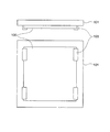
図1は、一実施形態によるレチクル保持部材101の構成を示す図である。レチクル100は、パターンが形成された面と反対側の面(以下において、レチクル100の裏面とも呼称する)がレチクル保持部材の面に接するようにレチクル保持部材101によって保持される。本実施形態において、レチクル保持部材101の、レチクル100の裏面に当接する面は、レチクル100の裏面よりも広く、レチクル保持部材101の周縁部は、レチクルより突出している。
FIG. 1 is a diagram illustrating a configuration of a
レチクル保持部材101は、レチクル押え103を備え、レチクル押え103は、機械的にレチクル100を押える。レチクル保持部材101は、セラミクス、低熱膨張ガラスなどで形成される。レチクル押え103は、金属やプラスチックなどで形成され、ネジ留めなどによってレチクル保持部材101に固定される。なお、レチクル押え103はレチクルを固定することができる構成であれば、機械的なものに限られず、他の方法によるものでも用いることができる。また、レチクル押え103はレチクルを着脱可能に固定する構成であることが好ましい。このように構成すると、レチクルの洗浄あるいは検査を行う際に、取り外す事ができる。
The
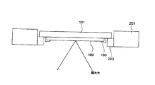
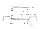
図2は、露光装置のレチクル・ステージ201に取り付けられた、一実施形態による、レチクル100を保持するレチクル保持部材101を示す図である。レチクル・ステージ201は、露光光が照射される方向に開放された、レチクル保持部材101を取り付ける空間を備え、レチクル保持部材101の、レチクル100の周縁に突出した部分を支持する支持部203を備える。レチクル100は、レチクル押え103によってレチクル保持部材101に保持され、レチクル保持部材101は、支持部203によって支持されているので、停電時でもレチクル100やレチクル保持部材101が落下することはない。言い換えるならば、レチクル保持部材101の周縁部の下面は支持部203の上面に重力方向上側から乗っかって支持されている。この状態でレチクルのパターンが形成された面に露光光を照射して投影露光を行う。
FIG. 2 is a view showing a
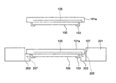
図3は、他の実施形態による、レチクル100を吸着するための静電チャック電極105を備えたレチクル保持部材101aを示す図である。レチクル100は、レチクル押え103によって、レチクル保持部材101に保持されるが、さらに、静電チャック電極105によって、レチクル100の裏面を、レチクル保持部材101aの面に吸着する。露光時には、静電チャック電極105によって、レチクル保持部材101aがレチクル100を吸着するので、レチクル100とレチクル保持部材101aを密着させることができ、レチクルの、パターンが形成されている面の平面度をさらに向上させることができる。静電チャック電極105に電源が供給されない場合でも、レチクル押え103によってレチクル100は固定されているので、レチクル100がレチクル保持部材101aから落下したりずれたりすることはない。
FIG. 3 is a view showing a
図3に示すように、レチクル保持部材101aの静電チャック電極105は、レチクル・ステージ201の支持部203の静電チャック給電線205から給電されてもよい。この場合に、レチクル保持部材101aは、レチクル・ステージ201の支持部203の静電チャック給電線205に対応する位置に、受電用の接点を備える。
As shown in FIG. 3, the
レチクル・ステージ201の支持部203から電源が供給されない場合でも、レチクル保持部材101aがレチクル100を吸着することができるように、レチクル保持部材101aにバッテリを搭載し、静電チャック電極105の電源としてもよい。
Even when power is not supplied from the
また、図3に示すように、レチクル保持部材101aを、レチクル・ステージ201の支持部203に固定するように、レチクル・ステージ201の支持部203にレチクル保持部材固定用静電チャック電極207を備えてもよい。レチクル保持部材固定用静電チャック電極207によってレチクル保持部材101aを吸着するので、レチクル・ステージ201とレチクル保持部材101aとの相対的な位置の変化が防止される。レチクル保持部材固定用静電チャック電極は、レチクル保持部材101aに備えてもよい。
Further, as shown in FIG. 3, a reticle holding member fixing
図10は他の実施形態によるレチクル保持部材101a1を示す図である。本実施形態において、レチクル保持部材101a1は、磁気吸着機構によってレチクル・ステージ201の支持部203a1に吸着される。レチクル保持部材101a1には磁性体209が備わり、支持部203a1には電磁石211が埋め込まれている。電磁石211は、例えばコイルである。磁性体及び電磁石を配置する位置は、図10では1箇所となっているが、レチクルを囲むようにリング状に配置しても構わないし、所定の場所(例えば3点)にのみ配置するようにしてもよい。また、磁性体を支持部203a1に配置し、電磁石をレチクル保持部材101a1側に配置してもよい。磁場発生手段である電磁石211に流す電流源は不図示であるが、その配置は当業者にとって自明である。
FIG. 10 is a view showing a reticle holding member 101a1 according to another embodiment. In the present embodiment, the reticle holding member 101a1 is attracted to the support portion 203a1 of the
静電吸着機構に比べて磁気吸着機構は、吸着物の離脱応答性を高くすることが可能である。すなわち、電磁石に流す電流をオフにすると相対的に速いスピードでレチクル保持部材101a1を支持部203a1から取り外すことが可能となる。したがって、レチクル交換に要する時間を短くすることができ、露光装置のスループットを向上させることが可能となる。なお、レチクル100はレチクル保持部101a1に静電吸着によって吸着されている。これは図3に示した実施形態と同じであり、上記実施形態と同様に取り扱うことが可能である。
Compared with the electrostatic adsorption mechanism, the magnetic adsorption mechanism can increase the detachment response of the adsorbate. That is, when the current flowing through the electromagnet is turned off, the reticle holding member 101a1 can be detached from the support portion 203a1 at a relatively high speed. Therefore, the time required for reticle replacement can be shortened, and the throughput of the exposure apparatus can be improved. The
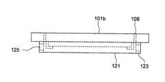
図4は、さらに他の実施形態による、ペリクル121を備えたペリクル・フレーム123を着脱できるように構成されたレチクル保持部材101bを示す図である。ペリクル・フレーム123は、磁石または一対の金具などによりレチクル保持部材101bに着脱できるようにしてもよい。ペリクルとは、レチクルのパターンが形成された面を保護する防塵用の薄膜である。ペリクルは薄膜であるので、レチクル保持部材101bを大気雰囲気から真空雰囲気に移動させる場合や、真空雰囲気から大気雰囲気に移動させる場合にペリクル両側の圧力差により破損しやすい。ペリクルの破損を防止するため、ペリクル・フレーム123には、ペリクル両側の圧力差を緩和するためのフィルタ125が設けられる。しかし、フィルタ125は、微細な異物の進入を防止するものであるため、コンダクタンスが低い。したがって、ペリクル・フレーム123のフィルタ125だけでは、ペリクル両側の圧力差が十分に緩和されない場合がある。このような場合に、図4に示すように、レチクル保持部材101bにも同様のフィルタ109を設けることにより、ペリクル両側の圧力差がさらに緩和される。
FIG. 4 is a view showing a
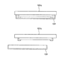
図5は、さらに他の実施形態による、リムーバブル・カバー131を着脱できるように構成されたレチクル保持部材101cを示す図である。リムーバブル・カバー131は、レチクル100が使用されない場合に、レチクル100のパターンが形成された面を保護し、レチクル100が使用される場合には取り外される。リムーバブル・カバー131は、磁石または一対の金具などによりレチクル保持部材101cに着脱できるようにしてもよい。なお、リムーバブル・カバーについては、米国特許公開番号2006-0087638を本発明では参照して援用する。
FIG. 5 is a view showing a
本実施形態によれば、リムーバブル・カバー131は、レチクル100自身ではなくレチクル保持部材101cに取り付けられる。したがって、レチクル100に触れることなく、リムーバブル・カバー131を着脱することができる。リムーバブル・カバー131が、レチクル100に触れることに起因する異物の発生が防止される。なお、リムーバブル・カバー131はレチクル・ステージにレチクルが設置される前、あるいは設置された後に外され、露光時はリムーバブル・カバー131が外された状態でレチクル100に露光光が照明される。露光が終了したレチクルはレチクル・ステージに固定された状態で、あるいはレチクル・ステージから外された状態で、再度リムーバブル・カバーによって覆われることで、パターン面が保護される。
According to the present embodiment, the
図8に一実施形態による露光装置を示した。ただし、図8では詳細を図示していないが、図2および図3に示すように、レチクル・ステージ201は、露光光が照射される方向に開放された、レチクル保持部材101を取り付ける空間を備え、レチクル保持部材101の、レチクル100の周縁に突出した部分を支持する支持部203を備える。
FIG. 8 shows an exposure apparatus according to an embodiment. Although details are not shown in FIG. 8, as shown in FIGS. 2 and 3,
一実施形態による露光装置においては、停電時でも、レチクルがレチクル・ステージ落下することはない。したがって、スループットが向上する。また、レチクル・ステージとレチクルの裏面との間の異物により、レチクルの、パターンが形成されている面の平面度が損なわれることはないので、露光装置の高い解像度が維持される。 In the exposure apparatus according to the embodiment, the reticle does not fall on the reticle stage even during a power failure. Therefore, the throughput is improved. In addition, since the foreign matter between the reticle stage and the back surface of the reticle does not impair the flatness of the surface of the reticle on which the pattern is formed, the high resolution of the exposure apparatus is maintained.
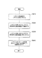
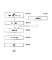
図6は、一実施形態による投影露光方法を示す流れ図である。 FIG. 6 is a flowchart showing a projection exposure method according to an embodiment.
図6のステップS010において、レチクル保持部材101にレチクル100を取り付ける。たとえば、図1に示すように、レチクル保持部材101のレチクル押え103によってレチクル100を保持する。
In step S 010 of FIG. 6, the
図6のステップS020において、レチクル100を取り付けたレチクル保持部材101を露光装置に搬送する。
In step S020 of FIG. 6, the
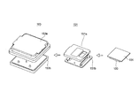
図7は、レチクル保持部材、クリーン・フィルタ・ポッドおよびレチクル・キャリアの関係を示す図である。図7に示すように、レチクル100を取り付けたレチクル保持部材101を、クリーン・フィルタ・ポッド151(上蓋151aおよび下蓋151b)に収納し、さらにレチクル・キャリア153(カバー153aおよびベース153b)に収納して搬送するようにしてもよい。レチクル100を取り付けたレチクル保持部材101を露光装置に搬送する途中で、レチクル・キャリア153およびクリーン・フィルタ・ポッド151は取り外される。
FIG. 7 is a diagram showing the relationship between the reticle holding member, the clean filter pod, and the reticle carrier. As shown in FIG. 7, a
図6のステップS030において、レチクル100を取り付けたレチクル保持部材101を、露光装置のレチクル・ステージ201に取り付ける。どのように取り付けるかについては、図2および図3を使用して既に説明した。なお、図2,3では記さなかったが、レチクルを搬送するロボットのエンドエフェクタがレチクルを設置する際にレチクル・ステージに衝突する可能性がある。そのような場合には、レチクル・ステージにエンドエフェクタが衝突しないように溝や開口を設けておくことが好ましい。さらに、レチクル・ステージにレチクルを取り付けるための専用の装置を配置することも可能である。
In step S030 of FIG. 6, the
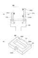
図11は、レチクルを搬送するエンドエフェクタ300およびレチクル・ステージ201の支持部203の構成の一例を示す図である。エンドエフェクタ300は2個の搬送アーム301aおよび301bと、2個の搬送アームがそれぞれ回転可能に固定される基部303とを有する。2個の搬送アーム301aおよび301bは、3個の支持部301a1、301b1および301b2を備え、点線で示したレチクル保持部材101がその上に支持される。支持部301a1、301b1および301b2には静電吸着等の吸着手段を配置してもよい。レチクル・ステージ201の支持部203には、レチクル保持部材101を載置する際に3個の支持部301a1、301b1および301b2が機械的に干渉しないように切り欠き部203a1、203b1および203b2が設けられている。レチクル保持部材101をレチクル・ステージに載置する際には、レチクル・ステージ201の位置まで搬送し、その後、エンドエフェクタ300を下方に(あるいはレチクル・ステージを上方に)移動することによって、3個の支持部301a1、301b1および301b2が切り欠き部203a1、203b1および203b2に進入する。その後、2個の搬送アーム301aおよび301を外側に開き、エンドエフェクタ300は上方へ移動する。この際、3個の支持部301a1、301b1および301b2はレチクル保持部材101と機械的に干渉しない。以上のようにして、レチクル・ステージ201にレチクル保持部材101に固定されたレチクル100が載置される。なお、レチクルを取り外す際には、上述の手順と逆の手順で取り外すことが可能である。
FIG. 11 is a diagram illustrating an example of the configuration of the
また、エンドエフェクタ300は、複数のレチクルを載置可能な複数(たとえば、4個)の搬送アームを有するタイプを採用することも可能である。
Further, the
図6のステップS040において、レチクル100のパターンが形成されている面を照射して投影露光を行う。なお、投影露光が終了したレチクルは、洗浄や検査の必要が無ければ、レチクル保持部材を毎回取り外さなくともよい。つまり、別のレチクルが露光に使われている間、真空環境あるいは大気環境でレチクル保持部材付のレチクルを待機させておき、次に使われるときには、図6のステップS020から行う事が可能である。
In step S040 of FIG. 6, projection exposure is performed by irradiating the surface on which the pattern of the
一実施形態による投影露光方法によれば、停電時でも、レチクルがレチクル・ステージ落下することはない。したがって、スループットが向上する。また、レチクル・ステージとレチクルの裏面との間の異物により、レチクルの、パターンが形成されている面の平面度が損なわれることはないので、露光装置の高い解像度が維持される。 According to the projection exposure method according to the embodiment, the reticle does not fall on the reticle stage even during a power failure. Therefore, the throughput is improved. In addition, since the foreign matter between the reticle stage and the back surface of the reticle does not impair the flatness of the surface of the reticle on which the pattern is formed, the high resolution of the exposure apparatus is maintained.
なお、本実施の形態では、レチクル保持部材101がレチクルの裏面全体を覆うように構成されているが、レチクル裏面の一部を覆うように構成することもできる。この場合、静電チャックの電極は裏面を覆っている部分のみに配置すればよい。また、レチクルをレチクルの裏面から固定する必要が無ければ、レチクルの裏面にはレチクル保持部材101を配置せず、レチクルの側面部のみに枠状にレチクル保持部材を配置することも可能である。
In this embodiment,
図12は、マイクロデバイスの製造工程の一例を示す流れ図である。 FIG. 12 is a flowchart showing an example of a microdevice manufacturing process.
ステップS1010において、マイクロデバイスの機能・性能設計を行う。 In step S1010, the function / performance design of the microdevice is performed.
ステップS1020において、ステップS1010における設計結果に基づいてマスク(レチクル)を製作する。 In step S1020, a mask (reticle) is manufactured based on the design result in step S1010.
ステップS1030において、デバイスの基材である基板を製造する。 In step S1030, a substrate that is a base material of the device is manufactured.
ステップS1040において、基板処理を行う。基板処理は、上述の実施形態にしたがって、レチクルを介した露光光で基板を露光すること、および露光した基板を現像することを含む。 In step S1040, substrate processing is performed. Substrate processing includes exposing the substrate with exposure light through a reticle and developing the exposed substrate in accordance with the above-described embodiments.
ステップS1050において、マイクロデバイスを組み立てる。マイクロデバイスの組み立ては、ダイシング工程、ボンディング工程、パッケージング工程などの加工工程を含む。 In step S1050, a microdevice is assembled. The assembly of the microdevice includes processing steps such as a dicing step, a bonding step, and a packaging step.
ステップS1060において、マイクロデバイスの検査を行う。 In step S1060, the micro device is inspected.
Claims (22)
請求項1から14のいずれかに記載のレチクル保持部材に、レチクルを取り付け、
レチクルを取り付けた、当該レチクル保持部材を露光装置まで搬送し、
レチクルを取り付けた、当該レチクル保持部材を、露光装置のレチクル・ステージに取り付け、
レチクルのパターンが形成されている面に光を照射して投影露光を行う、投影露光方法。A projection exposure method comprising:
A reticle is attached to the reticle holding member according to any one of claims 1 to 14,
Transport the reticle holding member with the reticle attached to the exposure apparatus,
The reticle holding member to which the reticle is attached is attached to the reticle stage of the exposure apparatus,
A projection exposure method for performing projection exposure by irradiating light onto a surface on which a reticle pattern is formed.
前記基板を現像することと、を含むデバイス製造方法。Exposing the substrate using the exposure method of claim 21;
Developing the substrate.
Applications Claiming Priority (3)
| Application Number | Priority Date | Filing Date | Title |
|---|---|---|---|
| JP2006190639 | 2006-07-11 | ||
| JP2006190639 | 2006-07-11 | ||
| PCT/JP2007/062229 WO2008007521A1 (en) | 2006-07-11 | 2007-06-18 | Reticle holding member, reticle stage, exposure apparatus, projection exposure method and device manufacturing method |
Publications (1)
| Publication Number | Publication Date |
|---|---|
| JPWO2008007521A1 true JPWO2008007521A1 (en) | 2009-12-10 |
Family
ID=38923086
Family Applications (1)
| Application Number | Title | Priority Date | Filing Date |
|---|---|---|---|
| JP2008524743A Pending JPWO2008007521A1 (en) | 2006-07-11 | 2007-06-18 | Reticle holding member, reticle stage, exposure apparatus, projection exposure method, and device manufacturing method |
Country Status (4)
| Country | Link |
|---|---|
| US (1) | US20080024751A1 (en) |
| JP (1) | JPWO2008007521A1 (en) |
| TW (1) | TW200811591A (en) |
| WO (1) | WO2008007521A1 (en) |
Families Citing this family (17)
| Publication number | Priority date | Publication date | Assignee | Title |
|---|---|---|---|---|
| DE102008041436A1 (en) * | 2007-10-02 | 2009-04-09 | Carl Zeiss Smt Ag | Optical membrane element |
| TWI461856B (en) * | 2008-09-24 | 2014-11-21 | Univ Ming Chi Technology | With a precise alignment of the tilt exposure mechanism |
| TW201015230A (en) | 2008-10-03 | 2010-04-16 | Univ Nat Chiao Tung | Immersion inclined lithography apparatus and tank thereof |
| EP2555052B1 (en) * | 2010-04-02 | 2024-10-16 | Shin-Etsu Chemical Co., Ltd. | Photomask unit and method of manufacturing same |
| EP2397905A1 (en) * | 2010-06-15 | 2011-12-21 | Applied Materials, Inc. | Magnetic holding device and method for holding a substrate |
| JP5609663B2 (en) | 2011-01-18 | 2014-10-22 | 旭硝子株式会社 | Glass substrate holding means and EUV mask blank manufacturing method using the same |
| JP6044092B2 (en) * | 2012-03-27 | 2016-12-14 | 大日本印刷株式会社 | Original plate setting device and copying machine |
| US10459353B2 (en) | 2013-03-15 | 2019-10-29 | Taiwan Semiconductor Manufacturing Company, Ltd. | Lithography system with an embedded cleaning module |
| US20150131071A1 (en) * | 2013-11-08 | 2015-05-14 | Samsung Electronics Co., Ltd. | Semiconductor device manufacturing apparatus |
| CN120010179A (en) * | 2015-02-03 | 2025-05-16 | Asml荷兰有限公司 | Mask assembly and associated method |
| CN104749874A (en) * | 2015-03-26 | 2015-07-01 | 京东方科技集团股份有限公司 | Mask plate, mask exposure apparatus and mask exposure method |
| KR102502727B1 (en) * | 2015-11-09 | 2023-02-23 | 삼성전자주식회사 | reticle and exposure apparatus including the same |
| US10714371B2 (en) * | 2017-11-16 | 2020-07-14 | Taiwan Semiconductor Manufacturing Co., Ltd. | Method and apparatus for lithography in semiconductor fabrication |
| EP3779594B1 (en) | 2018-03-27 | 2023-11-08 | Mitsui Chemicals, Inc. | Supporting frame for pellicle, pellicle, method for manufacturing same, exposure master using same, and method for manufacturing semiconductor device |
| TWI741848B (en) * | 2018-10-29 | 2021-10-01 | 家登精密工業股份有限公司 | Reticle retaining system |
| TWI767515B (en) * | 2020-05-14 | 2022-06-11 | 家登精密工業股份有限公司 | Container for accommodating substrate with effective hermetic sealing |
| WO2026012667A1 (en) * | 2024-07-08 | 2026-01-15 | Asml Netherlands B.V. | Reticle capture arrangement for a lithographic apparatus |
Citations (20)
| Publication number | Priority date | Publication date | Assignee | Title |
|---|---|---|---|---|
| JPS6433927A (en) * | 1987-07-30 | 1989-02-03 | Canon Kk | Mask holder and mask conveying method using the same |
| JPH05335218A (en) * | 1992-03-31 | 1993-12-17 | Canon Inc | X-ray mask and manufacturing method thereof, device manufacturing method using the X-ray mask, and X-ray exposure apparatus |
| JPH09213626A (en) * | 1996-02-06 | 1997-08-15 | Canon Inc | Original plate holding apparatus and exposure apparatus using the same |
| JPH1050584A (en) * | 1996-08-07 | 1998-02-20 | Nikon Corp | Mask holding device |
| JPH10209018A (en) * | 1997-01-24 | 1998-08-07 | Nippon Telegr & Teleph Corp <Ntt> | X-ray mask frame and method of holding X-ray mask |
| JP2001023886A (en) * | 1999-07-08 | 2001-01-26 | Nikon Corp | Sample holding device and exposure device |
| JP2001176791A (en) * | 1999-12-21 | 2001-06-29 | Shin Etsu Chem Co Ltd | Exposure method, exposure apparatus and pellicle |
| JP2002313713A (en) * | 2001-04-19 | 2002-10-25 | Nikon Corp | Reticle, exposure apparatus and exposure method using the same |
| JP2002324757A (en) * | 2001-03-01 | 2002-11-08 | Asml Netherlands Bv | Mask handling method, instrument or apparatus including mask and gripper therefor, device manufacturing method and device manufactured thereby |
| JP2003511868A (en) * | 1999-10-08 | 2003-03-25 | エーエスエムエル ユーエス,インコーポレイテッド | Removable cover for protecting a reticle, system including the cover, and method of using the cover |
| JP2003257852A (en) * | 2002-02-22 | 2003-09-12 | Asml Netherlands Bv | System and method using a two-part cover to protect a reticle |
| JP2004153122A (en) * | 2002-10-31 | 2004-05-27 | Nikon Corp | Aligner |
| JP2005045253A (en) * | 2003-07-22 | 2005-02-17 | Asml Netherlands Bv | Lithographic system, method of manufacturing device, and device manufactured by the method |
| JP2005129959A (en) * | 2003-10-27 | 2005-05-19 | Asml Netherlands Bv | Reticle holder and reticle assembly |
| JP2005150759A (en) * | 2004-12-15 | 2005-06-09 | Nikon Corp | Scanning exposure equipment |
| JP2005148741A (en) * | 2003-11-12 | 2005-06-09 | Asml Holding Nv | Method and apparatus for kinematic registration of reticle |
| JP2006005240A (en) * | 2004-06-18 | 2006-01-05 | Nikon Corp | Substrate transport apparatus, substrate transport method, and exposure apparatus |
| JP2006013208A (en) * | 2004-06-28 | 2006-01-12 | Canon Inc | Exposure equipment |
| WO2006051896A1 (en) * | 2004-11-15 | 2006-05-18 | Nikon Corporation | Substrate carrying device, substrate carrying method, and exposure device |
| JP2006153899A (en) * | 2004-10-29 | 2006-06-15 | Nikon Corp | Reticle protection member, reticle transport apparatus, exposure apparatus, and reticle transport method |
Family Cites Families (3)
| Publication number | Priority date | Publication date | Assignee | Title |
|---|---|---|---|---|
| US6136168A (en) * | 1993-01-21 | 2000-10-24 | Tdk Corporation | Clean transfer method and apparatus therefor |
| US6639650B2 (en) * | 1999-12-21 | 2003-10-28 | Shin-Etsu Chemical Co., Ltd. | Light exposure method, light exposure apparatus, pellicle and method for relieving warpage of pellicle membrane |
| JP2006128188A (en) * | 2004-10-26 | 2006-05-18 | Nikon Corp | Substrate transport apparatus, substrate transport method, and exposure apparatus |
-
2007
- 2007-06-18 JP JP2008524743A patent/JPWO2008007521A1/en active Pending
- 2007-06-18 WO PCT/JP2007/062229 patent/WO2008007521A1/en not_active Ceased
- 2007-07-10 US US11/827,371 patent/US20080024751A1/en not_active Abandoned
- 2007-07-10 TW TW096125051A patent/TW200811591A/en unknown
Patent Citations (20)
| Publication number | Priority date | Publication date | Assignee | Title |
|---|---|---|---|---|
| JPS6433927A (en) * | 1987-07-30 | 1989-02-03 | Canon Kk | Mask holder and mask conveying method using the same |
| JPH05335218A (en) * | 1992-03-31 | 1993-12-17 | Canon Inc | X-ray mask and manufacturing method thereof, device manufacturing method using the X-ray mask, and X-ray exposure apparatus |
| JPH09213626A (en) * | 1996-02-06 | 1997-08-15 | Canon Inc | Original plate holding apparatus and exposure apparatus using the same |
| JPH1050584A (en) * | 1996-08-07 | 1998-02-20 | Nikon Corp | Mask holding device |
| JPH10209018A (en) * | 1997-01-24 | 1998-08-07 | Nippon Telegr & Teleph Corp <Ntt> | X-ray mask frame and method of holding X-ray mask |
| JP2001023886A (en) * | 1999-07-08 | 2001-01-26 | Nikon Corp | Sample holding device and exposure device |
| JP2003511868A (en) * | 1999-10-08 | 2003-03-25 | エーエスエムエル ユーエス,インコーポレイテッド | Removable cover for protecting a reticle, system including the cover, and method of using the cover |
| JP2001176791A (en) * | 1999-12-21 | 2001-06-29 | Shin Etsu Chem Co Ltd | Exposure method, exposure apparatus and pellicle |
| JP2002324757A (en) * | 2001-03-01 | 2002-11-08 | Asml Netherlands Bv | Mask handling method, instrument or apparatus including mask and gripper therefor, device manufacturing method and device manufactured thereby |
| JP2002313713A (en) * | 2001-04-19 | 2002-10-25 | Nikon Corp | Reticle, exposure apparatus and exposure method using the same |
| JP2003257852A (en) * | 2002-02-22 | 2003-09-12 | Asml Netherlands Bv | System and method using a two-part cover to protect a reticle |
| JP2004153122A (en) * | 2002-10-31 | 2004-05-27 | Nikon Corp | Aligner |
| JP2005045253A (en) * | 2003-07-22 | 2005-02-17 | Asml Netherlands Bv | Lithographic system, method of manufacturing device, and device manufactured by the method |
| JP2005129959A (en) * | 2003-10-27 | 2005-05-19 | Asml Netherlands Bv | Reticle holder and reticle assembly |
| JP2005148741A (en) * | 2003-11-12 | 2005-06-09 | Asml Holding Nv | Method and apparatus for kinematic registration of reticle |
| JP2006005240A (en) * | 2004-06-18 | 2006-01-05 | Nikon Corp | Substrate transport apparatus, substrate transport method, and exposure apparatus |
| JP2006013208A (en) * | 2004-06-28 | 2006-01-12 | Canon Inc | Exposure equipment |
| JP2006153899A (en) * | 2004-10-29 | 2006-06-15 | Nikon Corp | Reticle protection member, reticle transport apparatus, exposure apparatus, and reticle transport method |
| WO2006051896A1 (en) * | 2004-11-15 | 2006-05-18 | Nikon Corporation | Substrate carrying device, substrate carrying method, and exposure device |
| JP2005150759A (en) * | 2004-12-15 | 2005-06-09 | Nikon Corp | Scanning exposure equipment |
Also Published As
| Publication number | Publication date |
|---|---|
| WO2008007521A1 (en) | 2008-01-17 |
| US20080024751A1 (en) | 2008-01-31 |
| TW200811591A (en) | 2008-03-01 |
Similar Documents
| Publication | Publication Date | Title |
|---|---|---|
| JPWO2008007521A1 (en) | Reticle holding member, reticle stage, exposure apparatus, projection exposure method, and device manufacturing method | |
| KR101496076B1 (en) | Substrate transfer apparatus, substrate transfer method and exposure apparatus | |
| TWI467340B (en) | An exposure method and an element manufacturing method, and a substrate and a manufacturing method thereof | |
| JP3960820B2 (en) | Mask handover method and device manufacturing method | |
| CN109814330B (en) | Mask, mask container, and method for discharging electrostatic charge accumulated on mask | |
| WO2004102646A1 (en) | Exposure apparatus and method for manufacturing device | |
| TW200410764A (en) | A method of cleaning by removing particles from surfaces, a cleaning apparatus and a lithographic projection apparatus | |
| CN1311301C (en) | Photoetching projection device | |
| TW202125676A (en) | Method for processing semiconductor wafer | |
| KR20210010754A (en) | method for managing Extreme Ultraviolet light reticle and manufacturing method of semiconductor device including the same | |
| JP2013506268A (en) | Exposure apparatus and device manufacturing method | |
| US20050286202A1 (en) | Electrostatic chuck, device manufacturing apparatus, and device manufacturing method | |
| JPWO2008129982A1 (en) | Substrate processing method and system, and device manufacturing method | |
| CN104049469A (en) | Lithography system with embedded cleaning module | |
| US7656507B2 (en) | Processing unit, exposure apparatus having the processing unit, and protection unit | |
| US7430037B2 (en) | Reticle cassette and exposure apparatus using reticle cassette | |
| US20050095829A1 (en) | Housing unit and exposure method using the same | |
| JP2009147227A (en) | Cleaning device, cleaning method, exposure apparatus, exposure method, and device manufacturing method | |
| US20080212050A1 (en) | Apparatus and methods for removing immersion liquid from substrates using temperature gradient | |
| JPWO2008075749A1 (en) | Exposure method and apparatus, and substrate holding apparatus | |
| JP2011204864A (en) | Reflection type mask, aligner, exposure method, and device manufacturing method | |
| JP2009267401A (en) | Exposure apparatus, cleaning method, and device fabricating method | |
| TWI916605B (en) | Positioning device, photolithography device and article manufacturing method | |
| JP2011061130A (en) | Aligner and exposure method, and method of manufacturing device | |
| TWI259333B (en) | Method and apparatus for maintaining a machine part |
Legal Events
| Date | Code | Title | Description |
|---|---|---|---|
| A621 | Written request for application examination |
Free format text: JAPANESE INTERMEDIATE CODE: A621 Effective date: 20100531 |
|
| A521 | Request for written amendment filed |
Free format text: JAPANESE INTERMEDIATE CODE: A523 Effective date: 20100608 |
|
| A131 | Notification of reasons for refusal |
Free format text: JAPANESE INTERMEDIATE CODE: A131 Effective date: 20120306 |
|
| A02 | Decision of refusal |
Free format text: JAPANESE INTERMEDIATE CODE: A02 Effective date: 20120710 |