JPWO2006009254A1 - Support apparatus, stage apparatus, exposure apparatus, and device manufacturing method - Google Patents
Support apparatus, stage apparatus, exposure apparatus, and device manufacturing method Download PDFInfo
- Publication number
- JPWO2006009254A1 JPWO2006009254A1 JP2006529300A JP2006529300A JPWO2006009254A1 JP WO2006009254 A1 JPWO2006009254 A1 JP WO2006009254A1 JP 2006529300 A JP2006529300 A JP 2006529300A JP 2006529300 A JP2006529300 A JP 2006529300A JP WO2006009254 A1 JPWO2006009254 A1 JP WO2006009254A1
- Authority
- JP
- Japan
- Prior art keywords
- support
- fluid
- stage
- cylinder
- piston
- Prior art date
- Legal status (The legal status is an assumption and is not a legal conclusion. Google has not performed a legal analysis and makes no representation as to the accuracy of the status listed.)
- Withdrawn
Links
Images


Classifications
-
- G—PHYSICS
- G03—PHOTOGRAPHY; CINEMATOGRAPHY; ANALOGOUS TECHNIQUES USING WAVES OTHER THAN OPTICAL WAVES; ELECTROGRAPHY; HOLOGRAPHY
- G03F—PHOTOMECHANICAL PRODUCTION OF TEXTURED OR PATTERNED SURFACES, e.g. FOR PRINTING, FOR PROCESSING OF SEMICONDUCTOR DEVICES; MATERIALS THEREFOR; ORIGINALS THEREFOR; APPARATUS SPECIALLY ADAPTED THEREFOR
- G03F7/00—Photomechanical, e.g. photolithographic, production of textured or patterned surfaces, e.g. printing surfaces; Materials therefor, e.g. comprising photoresists; Apparatus specially adapted therefor
- G03F7/70—Microphotolithographic exposure; Apparatus therefor
- G03F7/70691—Handling of masks or workpieces
- G03F7/70758—Drive means, e.g. actuators, motors for long- or short-stroke modules or fine or coarse driving
-
- G—PHYSICS
- G03—PHOTOGRAPHY; CINEMATOGRAPHY; ANALOGOUS TECHNIQUES USING WAVES OTHER THAN OPTICAL WAVES; ELECTROGRAPHY; HOLOGRAPHY
- G03F—PHOTOMECHANICAL PRODUCTION OF TEXTURED OR PATTERNED SURFACES, e.g. FOR PRINTING, FOR PROCESSING OF SEMICONDUCTOR DEVICES; MATERIALS THEREFOR; ORIGINALS THEREFOR; APPARATUS SPECIALLY ADAPTED THEREFOR
- G03F7/00—Photomechanical, e.g. photolithographic, production of textured or patterned surfaces, e.g. printing surfaces; Materials therefor, e.g. comprising photoresists; Apparatus specially adapted therefor
- G03F7/70—Microphotolithographic exposure; Apparatus therefor
- G03F7/70691—Handling of masks or workpieces
- G03F7/70716—Stages
-
- F—MECHANICAL ENGINEERING; LIGHTING; HEATING; WEAPONS; BLASTING
- F16—ENGINEERING ELEMENTS AND UNITS; GENERAL MEASURES FOR PRODUCING AND MAINTAINING EFFECTIVE FUNCTIONING OF MACHINES OR INSTALLATIONS; THERMAL INSULATION IN GENERAL
- F16C—SHAFTS; FLEXIBLE SHAFTS; ELEMENTS OR CRANKSHAFT MECHANISMS; ROTARY BODIES OTHER THAN GEARING ELEMENTS; BEARINGS
- F16C29/00—Bearings for parts moving only linearly
- F16C29/02—Sliding-contact bearings
- F16C29/025—Hydrostatic or aerostatic
-
- F—MECHANICAL ENGINEERING; LIGHTING; HEATING; WEAPONS; BLASTING
- F16—ENGINEERING ELEMENTS AND UNITS; GENERAL MEASURES FOR PRODUCING AND MAINTAINING EFFECTIVE FUNCTIONING OF MACHINES OR INSTALLATIONS; THERMAL INSULATION IN GENERAL
- F16C—SHAFTS; FLEXIBLE SHAFTS; ELEMENTS OR CRANKSHAFT MECHANISMS; ROTARY BODIES OTHER THAN GEARING ELEMENTS; BEARINGS
- F16C32/00—Bearings not otherwise provided for
- F16C32/06—Bearings not otherwise provided for with moving member supported by a fluid cushion formed, at least to a large extent, otherwise than by movement of the shaft, e.g. hydrostatic air-cushion bearings
- F16C32/0603—Bearings not otherwise provided for with moving member supported by a fluid cushion formed, at least to a large extent, otherwise than by movement of the shaft, e.g. hydrostatic air-cushion bearings supported by a gas cushion, e.g. an air cushion
- F16C32/0614—Bearings not otherwise provided for with moving member supported by a fluid cushion formed, at least to a large extent, otherwise than by movement of the shaft, e.g. hydrostatic air-cushion bearings supported by a gas cushion, e.g. an air cushion the gas being supplied under pressure, e.g. aerostatic bearings
-
- G—PHYSICS
- G03—PHOTOGRAPHY; CINEMATOGRAPHY; ANALOGOUS TECHNIQUES USING WAVES OTHER THAN OPTICAL WAVES; ELECTROGRAPHY; HOLOGRAPHY
- G03F—PHOTOMECHANICAL PRODUCTION OF TEXTURED OR PATTERNED SURFACES, e.g. FOR PRINTING, FOR PROCESSING OF SEMICONDUCTOR DEVICES; MATERIALS THEREFOR; ORIGINALS THEREFOR; APPARATUS SPECIALLY ADAPTED THEREFOR
- G03F7/00—Photomechanical, e.g. photolithographic, production of textured or patterned surfaces, e.g. printing surfaces; Materials therefor, e.g. comprising photoresists; Apparatus specially adapted therefor
- G03F7/70—Microphotolithographic exposure; Apparatus therefor
- G03F7/708—Construction of apparatus, e.g. environment aspects, hygiene aspects or materials
- G03F7/70808—Construction details, e.g. housing, load-lock, seals or windows for passing light in or out of apparatus
- G03F7/70816—Bearings
-
- G—PHYSICS
- G03—PHOTOGRAPHY; CINEMATOGRAPHY; ANALOGOUS TECHNIQUES USING WAVES OTHER THAN OPTICAL WAVES; ELECTROGRAPHY; HOLOGRAPHY
- G03F—PHOTOMECHANICAL PRODUCTION OF TEXTURED OR PATTERNED SURFACES, e.g. FOR PRINTING, FOR PROCESSING OF SEMICONDUCTOR DEVICES; MATERIALS THEREFOR; ORIGINALS THEREFOR; APPARATUS SPECIALLY ADAPTED THEREFOR
- G03F7/00—Photomechanical, e.g. photolithographic, production of textured or patterned surfaces, e.g. printing surfaces; Materials therefor, e.g. comprising photoresists; Apparatus specially adapted therefor
- G03F7/70—Microphotolithographic exposure; Apparatus therefor
- G03F7/708—Construction of apparatus, e.g. environment aspects, hygiene aspects or materials
- G03F7/7085—Detection arrangement, e.g. detectors of apparatus alignment possibly mounted on wafers, exposure dose, photo-cleaning flux, stray light, thermal load
-
- G—PHYSICS
- G12—INSTRUMENT DETAILS
- G12B—CONSTRUCTIONAL DETAILS OF INSTRUMENTS, OR COMPARABLE DETAILS OF OTHER APPARATUS, NOT OTHERWISE PROVIDED FOR
- G12B5/00—Adjusting position or attitude, e.g. level, of instruments or other apparatus, or of parts thereof; Compensating for the effects of tilting or acceleration, e.g. for optical apparatus
Landscapes
- Engineering & Computer Science (AREA)
- General Engineering & Computer Science (AREA)
- Physics & Mathematics (AREA)
- General Physics & Mathematics (AREA)
- Mechanical Engineering (AREA)
- Health & Medical Sciences (AREA)
- Environmental & Geological Engineering (AREA)
- Epidemiology (AREA)
- Public Health (AREA)
- Exposure And Positioning Against Photoresist Photosensitive Materials (AREA)
- Bearings For Parts Moving Linearly (AREA)
Abstract
ピストンとシリンダとの相対移動の応答性向上等を図ることができる支持装置、ステージ装置、露光装置等を提案する。シリンダ部(311)と、シリンダ部(311)の内側に設けられてZ方向に移動可能なピストン部(312)と、シリンダ部311の内壁(311c)とピストン部(312)の外壁312d)との間の少なくとも一部に形成された流体軸受(307)とを備え、シリンダ部(311)とピストン部(312)により生成される付勢力によって被支持部材(42)を支持部材(43)に対してZ方向に支持する支持装置(300)であって、流体軸受(307)とシリンダ部(311)の内部に、それぞれ独立して流体(G1,G2)を供給する。A support device, a stage device, an exposure device, and the like that can improve the response of the relative movement between the piston and the cylinder are proposed. A cylinder part (311), a piston part (312) provided inside the cylinder part (311) and movable in the Z direction, an inner wall (311c) of the cylinder part 311 and an outer wall 312d of the piston part (312) And a hydrodynamic bearing (307) formed at least in part between the supported member (42) and the supporting member (43) by the urging force generated by the cylinder portion (311) and the piston portion (312). On the other hand, it is a support device (300) that supports in the Z direction, and supplies fluids (G1, G2) to the fluid bearing (307) and the cylinder part (311) independently.
Description
本発明は、物体を支持する支持装置及びその支持装置を備えるステージ装置、並びに該ステージ装置を備える露光装置等に関する。
本願は、2004年7月23日に出願された特願2004−215434号に基づき優先権を主張し、その内容をここに援用する。The present invention relates to a support device that supports an object, a stage device including the support device, an exposure apparatus including the stage device, and the like.
This application claims priority based on Japanese Patent Application No. 2004-215434 for which it applied on July 23, 2004, and uses the content here.
半導体素子、液晶表示素子等を製造するためのリソグラフィエ程では、マスク又はレチクル(以下「レチクル」と総称する)に形成されたパターンを投影光学系を介してレジスト等が塗布されたウエハ又はガラスプレート等の感光物体(以下、「ウエハ」と総称する)上に転写するステップ・アンド・リピート方式の縮小投影露光装置(いわゆるステッパ)や、このステッパに改良を加えたステップ・アンド・スキャン方式の走査型投影露光装置(いわゆるスキャニング・ステッパ)などが主として用いられている。 In a lithography process for manufacturing a semiconductor element, a liquid crystal display element, etc., a wafer or glass in which a resist or the like is applied to a pattern formed on a mask or a reticle (hereinafter collectively referred to as “reticle”) via a projection optical system Step-and-repeat type reduction projection exposure apparatus (so-called stepper) that transfers onto a photosensitive object such as a plate (hereinafter collectively referred to as “wafer”), or a step-and-scan type with improved stepper. A scanning projection exposure apparatus (so-called scanning stepper) is mainly used.
ステッパなどの投影露光装置では、ウエハを保持するテーブルと、テーブルを保持して水平面方向に2次元移動するステージと、このステージを駆動する2軸駆動リニアモータ等を備えたステージ装置が主流となっている。また、ステージ装置では、テーブルはステージに対し、例えば3つの支持ユニットにより支持されており、この支持ユニットによりテーブルがステージ上で水平面に対して微少に傾斜可能に構成されている。 In a projection exposure apparatus such as a stepper, a stage apparatus including a table that holds a wafer, a stage that holds the table and moves two-dimensionally in a horizontal plane, and a two-axis drive linear motor that drives the stage is the mainstream. ing. Further, in the stage apparatus, the table is supported with respect to the stage by, for example, three support units, and the support unit is configured so that the table can be slightly tilted with respect to the horizontal plane on the stage.
支持ユニットとしては、特開2000−56483号公報等に開示されるように、ピストン・シリンダとからなる自重支持部及びボイスコイルモータ等からなる駆動部とから構成され、自重支持部によりテーブルをその自重を補償しつつ支持すると共に、駆動部によりテーブルを重力方向に微少移動させるものが知られている。このような支持ユニットにおいては、テーブルの重量をガスの陽圧で支持するので、ボイスコイルモータ等によりテーブルの重量を支持する必要がなくなり、エネルギー消費を大幅に減少させることができる。本国際出願で指定した指定国(又は選択した選択国)の国内法令で許される限りにおいて、下記公報を援用して本明細書の一部とする。
上述した支持ユニットの自重支持部では、圧縮ガスをピストンとシリンダの間隙及びシリンダの内部に供給することにより、ピストンをシリンダに軸支(水平方向に拘束)すると共にピストンをシリンダに対して(重力方向に)移動させている。 In the self-weight support portion of the support unit described above, the compressed gas is supplied to the gap between the piston and the cylinder and the inside of the cylinder, so that the piston is pivotally supported (restrained in the horizontal direction) and the piston is moved against the cylinder (gravity). In the direction).
しかしながら、ピストンとシリンダの間隙及びシリンダの内部に供給される圧縮ガスは、同一給気系を介して供給されるため、例えば、シリンダのZ方向移動の応答性が十分でない等の問題がある。 However, since the compressed gas supplied to the gap between the piston and the cylinder and the inside of the cylinder is supplied through the same supply system, there is a problem that, for example, the responsiveness of the movement of the cylinder in the Z direction is not sufficient.
本発明は、上述した事情に鑑みてなされたもので、ピストンとシリンダとの相対移動の応答性向上等を図ることができる支持装置、ステージ装置、露光装置等を提案することを目的とする。 The present invention has been made in view of the above-described circumstances, and an object thereof is to propose a support device, a stage device, an exposure device, and the like that can improve the response of the relative movement between the piston and the cylinder.
本発明に係る支持装置、ステージ装置、露光装置、及びデバイスの製造方法では、上記課題を解決するために以下の手段を採用した。なお、各要素に付した括弧付きの符号はその要素の例示に過ぎず、各要素を限定するものではない。 In the support apparatus, stage apparatus, exposure apparatus, and device manufacturing method according to the present invention, the following means are employed in order to solve the above problems. In addition, the code | symbol with the parenthesis attached | subjected to each element is only the illustration of the element, and does not limit each element.
第1の発明は、シリンダ部(311)と、シリンダ部の内側に設けられて第1方向(Z)に移動可能なピストン部(312)と、シリンダ部の内壁(311c)とピストン部の外壁(312d)との間の少なくとも一部に形成された流体軸受(307)とを備え、シリンダ部とピストン部により生成される付勢力によって被支持部材(42)を支持部材(43)に対して第1方向に支持する支持装置(300)であって、流体軸受とシリンダ部の内部に、それぞれ独立して流体(G1,G2)を供給するようにした。 The first invention includes a cylinder part (311), a piston part (312) provided inside the cylinder part and movable in the first direction (Z), an inner wall (311c) of the cylinder part, and an outer wall of the piston part (312d) and a hydrodynamic bearing (307) formed at least in part between the support member (42) and the support member (43) by the urging force generated by the cylinder portion and the piston portion. In the supporting device (300) for supporting in the first direction, fluids (G1, G2) are independently supplied into the fluid bearing and the cylinder part.
この発明によれば、シリンダ部によるピストン部の軸支と、ピストン部のシリンダ部に対する相対移動とを独立に行うことができるので、ピストン部とシリンダ部による被支持部材への付勢の応答性を向上させることができる。 According to the present invention, since the axial support of the piston portion by the cylinder portion and the relative movement of the piston portion with respect to the cylinder portion can be performed independently, the responsiveness of the urging to the supported member by the piston portion and the cylinder portion is possible. Can be improved.
また、シリンダ部(311)の内部に流体(G1)を供給する第1供給装置(301)と、流体軸受(307)に流体(G2)を供給する第2供給装置(305)とを有し、第1供給装置から供給される流体の圧力と、第2供給装置から供給される流体の圧力とが異なるようにしたものでは、例えば、シリンダ部とピストン部の間に形成される流体軸受の剛性を向上させることができる。 The first supply device (301) for supplying the fluid (G1) to the inside of the cylinder part (311) and the second supply device (305) for supplying the fluid (G2) to the fluid bearing (307). In the case where the pressure of the fluid supplied from the first supply device is different from the pressure of the fluid supplied from the second supply device, for example, a fluid bearing formed between the cylinder portion and the piston portion is used. Stiffness can be improved.
また、シリンダ部(311)の内側に設けられた圧力室(313s)を有し、第1供給装置(301)は圧力室に流体(G1)を供給するものでは、圧力室に供給された流体により、付勢力を得ることができる。 The first chamber (311) has a pressure chamber (313s) provided inside the cylinder portion (311), and the first supply device (301) supplies the fluid (G1) to the pressure chamber. Thus, an urging force can be obtained.
また、圧力室(313s)が、シリンダ部(311)とは独立に設けられ、第1方向に伸縮可能な外殻(313)を有するものでは、圧力室に供給された流体の圧力を効率よく第1方向の付勢力に変換することができる。 Further, in the case where the pressure chamber (313s) is provided independently of the cylinder portion (311) and has an outer shell (313) that can expand and contract in the first direction, the pressure of the fluid supplied to the pressure chamber is efficiently increased. It can be converted into a biasing force in the first direction.
また、ピストン部(312)は、外殻(313)に接続されているものでは、外殻の伸縮に応じてピストン部を移動させることができる。 Further, when the piston portion (312) is connected to the outer shell (313), the piston portion can be moved according to the expansion and contraction of the outer shell.
また、圧力室(313s)と流体軸受(307)の間での流体(G1,G2)の移動が遮断されているものでは、相互に他方の圧力変動等による影響を受けることを防止することができる。 Further, in the case where the movement of the fluid (G1, G2) between the pressure chamber (313s) and the fluid bearing (307) is blocked, it is possible to prevent the fluid from being influenced by the other pressure fluctuation or the like. it can.
また、流体軸受(307)は、シリンダ部(311)の内壁(311c)とピストン部(312)の外壁(312d)の少なくとも一方に設けられた多孔質体(306)を有し、第2供給装置(305)は、多孔質体に流体(G2)を供給するものでは、シリンダ部の内壁に溝等を設けることなく、容易に気体軸受を形成することができる。 The fluid dynamic bearing (307) has a porous body (306) provided on at least one of the inner wall (311c) of the cylinder part (311) and the outer wall (312d) of the piston part (312), and the second supply When the device (305) supplies the fluid (G2) to the porous body, the gas bearing can be easily formed without providing a groove or the like on the inner wall of the cylinder portion.
また、ピストン部(312)の一端に配置されて第1方向(Z)に交差する平面に対して傾斜可能な中間部材(314)と、ピストン部と中間部材との間に形成された第2流体軸受(303)とを備え、第2流体軸受は、第1供給装置(301)と第2供給装置(305)の少なくとも一方から流体(G1,G2)を供給されるものでは、新たな流体供給装置を設けることなく、被支持部材を支持部材に対して傾斜可能に支持することが可能となる。 An intermediate member (314) that is disposed at one end of the piston portion (312) and can be inclined with respect to a plane that intersects the first direction (Z), and a second member formed between the piston portion and the intermediate member. A fluid bearing (303), and the second fluid bearing is supplied with fluid (G1, G2) from at least one of the first supply device (301) and the second supply device (305). It is possible to support the supported member so as to be tiltable with respect to the support member without providing a supply device.
また、中間部材(314)が、支持部材(43)或いは被支持部材(42)を支持する支持面(314a)を有し、支持部材又は被支持部材と支持面との間で第1方向(Z)と交差する方向に対して相対移動が可能であるものでは、被支持部材を支持部材に対して第1方向と交差する方向に移動可能とすることが可能となる。 Further, the intermediate member (314) has a support surface (314a) for supporting the support member (43) or the supported member (42), and a first direction (between the support member or the supported member and the support surface). In the case where the relative movement is possible with respect to the direction intersecting Z), the supported member can be moved in the direction intersecting the first direction with respect to the support member.
また、シリンダ部(311)が、支持部材(43)に接続されるように支持装置を設置することができる。 Moreover, a support apparatus can be installed so that a cylinder part (311) may be connected to a support member (43).
また、シリンダ部(311)が、被支持部材(42)に接続されるように支持装置を設置することができる。 Moreover, a support apparatus can be installed so that a cylinder part (311) may be connected to a to-be-supported member (42).
また、支持部材(43)或いは被支持部材(42)とシリンダ部(311)との間に、第1方向(Z)に略平行な力を発生させるアクチュエータ(330)を備えるものでは、被支持部材を支持部材に対して第1方向に正確に位置決め制御することが可能となる。 Further, in the case where an actuator (330) that generates a force substantially parallel to the first direction (Z) is provided between the support member (43) or the supported member (42) and the cylinder portion (311), the supported It becomes possible to accurately control the positioning of the member with respect to the support member in the first direction.
第2の発明は、第1部材(43)と、少なくとも1つの支持装置(300)によって第1部材に対して移動可能に支持された第2部材(42)と、を備えたステージ装置(40)において、支持装置が第1の発明の支持装置(300)であり、第2部材が被支持部材(42)の少なくとも一部を含むようにした。 The second invention is a stage device (40) comprising a first member (43) and a second member (42) supported by at least one support device (300) so as to be movable relative to the first member. ), The supporting device is the supporting device (300) of the first invention, and the second member includes at least a part of the supported member (42).
この発明によれば、少ない動力で第1部材に対する第2部材の重力方向の位置や姿勢を正確に制御することができる。 According to the present invention, the position and posture of the second member in the direction of gravity relative to the first member can be accurately controlled with a small amount of power.
また、案内面(81a)を有するベース(81)上を移動可能なステージ装置(80)であって、第1の発明の支持装置(300)を備え、支持装置によってベース上に支持されるものでは、ステージ装置を非接触にかつ自重を補償(キャンセル)させて支持するとともに、案内面に沿ってステージ装置を移動させることも可能となる。 A stage device (80) movable on a base (81) having a guide surface (81a), comprising the support device (300) of the first invention, and supported on the base by the support device Then, the stage device can be supported in a non-contact manner with its own weight compensated (cancelled), and the stage device can be moved along the guide surface.
第3の発明は、マスク(R)を保持するマスクステージ(20)と、基板(W)を保持する基板ステージ(40)とを有し、マスクに形成されたパターン(PA)を基板に露光する露光装置(EX)において、マスクステージと基板ステージの少なくとも一方に、第2の発明のステージ装置を用いるようにした。この発明によれば、マスク又は基板の重力方向に位置を少ない動力で正確に制御することができるので、高精度なパターンを基板上に露光することができる。 3rd invention has the mask stage (20) holding a mask (R), and the substrate stage (40) holding a board | substrate (W), and exposes the pattern (PA) formed in the mask to a board | substrate In the exposure apparatus (EX) to be used, the stage apparatus of the second invention is used for at least one of the mask stage and the substrate stage. According to the present invention, the position of the mask or the substrate in the direction of gravity can be accurately controlled with a small amount of power, so that a highly accurate pattern can be exposed on the substrate.
第4の発明は、リソグラフィ工程を含むデバイスの製造方法において、リソグラフィ工程において第3の発明の露光装置(EX)を用いるようにした。この発明によれば、高性能なデバイスを製造することができる。 According to a fourth aspect of the present invention, in the device manufacturing method including the lithography step, the exposure apparatus (EX) of the third aspect is used in the lithography step. According to the present invention, a high-performance device can be manufactured.
本発明により以下の効果を得ることができる。 The following effects can be obtained by the present invention.
ピストン部とシリンダ部による被支持部材への付勢の応答性を向上させることができるので、被支持部材の重力方向の位置や姿勢を迅速に変更することができる。また、シリンダ部とピストン部の間に形成される流体軸受の剛性を容易に向上させることができるので、水平方向の振動等が存在する場合であっても、ピストン部とシリンダ部との相対移動を円滑に行うことができる。 Since the responsiveness of the biasing to the supported member by the piston part and the cylinder part can be improved, the position and posture of the supported member in the direction of gravity can be quickly changed. In addition, since the rigidity of the fluid bearing formed between the cylinder part and the piston part can be easily improved, the relative movement between the piston part and the cylinder part can be achieved even when horizontal vibration or the like exists. Can be performed smoothly.
また、少ない動力で被支持部材の重力方向の位置や姿勢を正確に制御することができるので、露光装置においては、ウエハとマスクの相対位置を高精度に位置合わせすることができる。これにより、微細なパターンを有する高性能なデバイスを製造することができる。 Further, since the position and posture of the supported member in the direction of gravity can be accurately controlled with a small amount of power, the exposure apparatus can align the relative position of the wafer and the mask with high accuracy. Thereby, a high-performance device having a fine pattern can be manufactured.
20 レチクルステージ(マスクステージ) 40 ウエハステージ(基板ステージ、ステージ装置) 42 Zテーブル(被支持部材、第2部材) 43 XYテーブル(支持部材、第1部材) 80 ステージ装置 81 ウエハ定盤(ベース) 81a 案内面 82 XYZテーブル 300,300´,600 支持装置 301 給気系(第1供給装置) 303 気体静圧軸受(第2流体軸受) 304 気体静圧軸受(第3流体軸受) 305 給気系(第2供給装置) 306 多孔質体 307 気体静圧軸受(流体軸受) 311 シリンダ 311c 内周面(内壁) 312 ピストン 312d 外周面(外壁) 313 ベローズ(外殻) 313s 内部空間(圧力室) 314 スイベル(中間部材) 330 駆動部(アクチュエータ) G1,G2 圧縮ガス(流体) R レチクル(マスク) PA パターン W ウエハ(基板) EX 露光装置
20 reticle stage (mask stage) 40 wafer stage (substrate stage, stage device) 42 Z table (supported member, second member) 43 XY table (support member, first member) 80
以下、本発明の支持装置、ステージ装置、露光装置、及びデバイスの製造方法の実施形態について図を参照して説明する。 Hereinafter, embodiments of a support apparatus, a stage apparatus, an exposure apparatus, and a device manufacturing method according to the present invention will be described with reference to the drawings.
図1は、本発明の露光装置EXの一実施形態を示す概略構成図である。 FIG. 1 is a schematic block diagram showing an embodiment of the exposure apparatus EX of the present invention.
露光装置EXは、レチクル(マスク)Rとウエハ(基板)Wとを一次元方向に同期移動しつつ、レチクルRに形成されたパターンPAを投影光学系30を介してウエハW上の各ショット領域に転写するステップ・アンド・スキャン方式の走査型露光装置、すなわちいわゆるスキャニング・ステッパである。
The exposure apparatus EX moves a reticle (mask) R and a wafer (substrate) W synchronously in a one-dimensional direction, and applies a pattern PA formed on the reticle R to each shot area on the wafer W via the projection
そして、露光装置EXは、露光光ELによりレチクルRを照明する照明光学系10、レチクルRを保持するレチクルステージ20、レチクルRから射出される露光光ELをウエハW上に投射する投影光学系30、ウエハWを保持するウエハステージ40、露光装置EXを統括的に制御する制御装置50等を備える。
The exposure apparatus EX includes an illumination
そして、これらの各装置は、本体フレーム100或いは基礎フレーム200上に防振ユニット66,70等を介して支持される。
Each of these devices is supported on the main body frame 100 or the
なお、以下の説明において、投影光学系30の光軸AXと一致する方向をZ軸方向、Z軸方向に垂直な平面内でレチクルRとウエハWとの同期移動方向(走査方向)をY軸方向、Z軸方向及びY軸方向に垂直な方向(非走査方向)をX軸方向とする。更に、X軸、Y軸、及びZ軸まわり方向をそれぞれ、θX、θY、及びθZ方向とする。
In the following description, the direction that coincides with the optical axis AX of the projection
照明光学系10は、レチクルステージ20に支持されているレチクルRを露光光ELで照明するものであり、露光用光源、露光用光源から射出された光束の照度を均一化するオプティカルインテグレータ、オプティカルインテグレータからの露光光ELを集光するコンデンサレンズ、リレーレンズ系、露光光ELによるレチクルR上の照明領域をスリット状に設定する可変視野絞り等(いずれ不図示)を有している。
The illumination
照明光学系10から射出される露光光ELとしては、水銀ランプから射出される紫外域の輝線(g線、h線、i線)、KrFエキシマレーザ光(波長248nm)、ArFエキシマレーザ光(波長193nm)、F2レーザ光(波長157nm)等の紫外光が用いられる。
The exposure light EL emitted from the illumination
そして、光源5から射出されたレーザビームは、照明光学系10に入射され、レーザビームの断面形状がスリット状又は矩形状(多角形)に整形されるとともに照度分布がほぼ均一な照明光(露光光)ELとなってレチクルR上に照射される。
The laser beam emitted from the
そして、この照明光学系10は、本体フレーム100を構成する第2支持盤120の上面に固定された照明系支持部材12によって支持される。
The illumination
レチクルステージ(マスクステージ)20は、レチクルRを支持しつつ、投影光学系30の光軸AXに垂直な平面内、すなわちXY平面内の2次元移動及びθZ方向の微小回転を行うものであって、レチクルRを保持するレチクル微動ステージと、レチクル微動ステージと一体に走査方向であるY軸方向に所定ストロークで移動するレチクル粗動ステージと、これらを移動させるリニアモータ等(いずれも不図示)を備える。そして、レチクル微動ステージには、矩形開口が形成されており、開口周辺部に設けられたレチクル吸着機構によりレチクルが真空吸着等により保持される。なお、レチクルステージ20は、前述のように粗動ステージと微動ステージとで構成する必要はなく、単独のステージでレチクルRの支持と位置決め(移動)とを行うように構成してもよい。
The reticle stage (mask stage) 20 supports the reticle R and performs two-dimensional movement in the plane perpendicular to the optical axis AX of the projection
レチクルステージ20上には移動鏡21が設けられ。また、移動鏡21に対向する位置にはレーザ干渉計22が設けられる。そして、レチクルステージ20上のレチクルRの2次元方向の位置及び回転角は、レーザ干渉計22によりリアルタイムで計測され、その計測結果は制御装置50に出力される。そして、制御装置50がレーザ干渉計22の計測結果に基づいてリニアモータ等を駆動することで、レチクルステージ20に支持されているレチクルRの位置決め等が行われる。
A
このレチクルステージ20は、本体フレーム100を構成する第2支持盤120の上面に不図示の非接触ベアリング(例えば気体静圧軸受)を介して浮上支持される。
The
投影光学系30は、レチクルRのパターンPAを所定の投影倍率βでウエハWに投影露光するものであって、ウエハW側の先端(下端)部に設けられた光学素子32を含む複数の光学素子で構成されており、これら光学素子は鏡筒31で支持される。本実施形態において、投影光学系30は、投影倍率βが例えば1/4あるいは1/5の縮小系である。なお、投影光学系30は等倍系及び拡大系のいずれでもよい。
The projection
そして、鏡筒31の外壁にはフランジ33が設けられ、フランジを有する円筒形のセンサ支持架台35に挿入される。更に、鏡筒31及びセンサ支持架台35は、本体フレーム100を構成する第1支持盤110に設けられた穴部113に挿入、支持される。そして、第1支持盤110は、防振ユニット66を介して、基礎フレーム200上にほぼ水平に支持される。
A flange 33 is provided on the outer wall of the
なお、センサ支持架台は、オートフォーカスセンサ等のセンサ類を支持する部材である。また、第1支持盤110とセンサ支持架台35との間には、不図示のキネマティックマウントが設けられ、投影光学系30のあおり角を調整することが可能である。
The sensor support base is a member that supports sensors such as an autofocus sensor. Further, a kinematic mount (not shown) is provided between the
ウエハステージ(基板ステージ、ステージ装置)40は、ウエハWを支持しつつ、XY平面内の2次元移動及びθZ方向の微小回転を行うものであって、ウエハWを保持するウエハホルダ41、ウエハWのレベリング及びフォーカシングを行うためにウエハホルダ41をZ軸方向、θX方向、及びθY方向の3自由度方向に微小駆動するZテーブル42、Zテーブル42をY軸方向に連続移動するとともにX軸方向にステップ移動するXYテーブル43、XYテーブル43をXY平面内で移動可能に支持するウエハ定盤44、Zテーブル42及びXYテーブル43とを一体として平行移動させるリニアモータ等からなる駆動部(不図示)等を備える。なお、Zテーブル42の代わりに、XYテーブル43に対して6自由度で駆動される微動テーブルを設けてもよい。この場合、駆動部330として、例えば、2個のX軸用駆動部、1個のY軸用駆動部、及び3個のZ軸用駆動部とで構成することができるが、これに限定されるものではない。
A wafer stage (substrate stage, stage device) 40 performs two-dimensional movement in the XY plane and minute rotation in the θZ direction while supporting the wafer W. The
また、Zテーブル42上には移動鏡47が設けられ、これに対向する位置にはレーザ干渉計48が設けられる。ウエハステージ40上のウエハWの2次元方向の位置、及び回転角はレーザ干渉計48によりリアルタイムで計測され、計測結果は制御装置50に出力される。そして、制御装置50がレーザ干渉計48の計測結果に基づいてリニアモータ等を駆動することでウエハステージ40に支持されているウエハWの位置決めを行う。
A
XYテーブル43の底面には、非接触ベアリングである複数のエアベアリング(エアパッド)45が固定されており、これらのエアパッド45によってXYテーブル43がウエハ定盤44上に、例えば数ミクロン程度のクリアランスを介して浮上支持される。また、ウエハ定盤44は、基礎フレーム200の支持盤210上に、防振ユニット70を介してほぼ水平に支持されている。
A plurality of air bearings (air pads) 45, which are non-contact bearings, are fixed to the bottom surface of the XY table 43. The
制御装置50は、露光装置EXを統括的に制御するものであり、各種演算及び制御を行う演算部の他、各種情報を記録する記憶部や入出力部等を備える。
The
そして、例えば、レーザ干渉計22,48の検出結果に基づいてレチクルR及びウエハWの位置を制御して、レチクルRに形成されたパターンPAの像をウエハW上のショット領域に転写する露光動作を繰り返し行う。
Then, for example, an exposure operation for controlling the positions of the reticle R and the wafer W based on the detection results of the
本体フレーム100は、投影光学系30を支持する第1支持盤110と、投影光学系30の上方に配置されるレチクルステージ20等を支持する第2支持盤120と、第1支持盤110と第2支持盤120との間に立設する複数の支柱130とから構成される。第1支持盤110は、上述したように、円筒状の投影光学系30の外径よりもやや大きく形成された穴部113が形成される。なお、第1支持盤110或いは第2支持盤120と複数の支柱130とは、締結手段等で連結される構造としてもよいし、これらを一体に形成した構造としてもよい。
The main body frame 100 includes a
そして、上述したように、本体フレーム100は、防振ユニット66を介して基礎フレーム200上に支持される。
As described above, the main body frame 100 is supported on the
基礎フレーム200は、その上面に防振ユニット70を介してウエハステージ40を支持する支持盤210と、支持盤210上に立設するとともに防振ユニット66を介して本体フレーム100を支持する複数の支柱220とから構成される。支持盤210と支柱220とは、締結手段等で連結される構造であっても、一体に形成される構造であってもよい。
The
そして、基礎フレーム200は、クリーンルーム等の床面F上に足部215を介して略水平に設置される。
And the
図2は、ウエハステージ40の拡大図であり、図3は、支持装置300を示す断面図である。
FIG. 2 is an enlarged view of the
上述したように、ウエハステージ40は、上面にウエハホルダ41が配置されたZテーブル(被支持部材、第2部材)42と、Zテーブル42と一体となってXY方向に移動するXYテーブル(支持部材、第1部材)43を有する。Zテーブル42とXYテーブル43の間には3つの支持装置300が配置され、これによりZテーブル42がXYテーブル43の上に三点支持される。
As described above, the
支持装置300は、自重支持部310と駆動部330とから構成される。
The
まず、自重支持部310は、ピストン312とシリンダ311等を有する。シリンダ311は、一端にフランジ部311fを有する円筒部材からなり、フランジ部311fがXYテーブル43の上に給気部円板302を挟んで固定される。ピストン312は、カップ形部材からなり、シリンダ311の内側に嵌合して重力方向(Z方向、第1方向)に移動可能に軸支される。そして、給気部円板302とシリンダ311とピストン312とにより、シリンダ311の内部に、後述するベローズ313が収容される内部空間が形成される。
First, the self-
また、ピストン312の上面312aには、スイベル(中間部材)314が載置される。ピストン312の上面312aは凹レンズ状に形成され、一方、スイベル314の下面314bは凸レンズ状に形成される。また、スイベル314の上面(支持面)314aは、平坦に形成されてZテーブル42の下面42bに対向する。
A swivel (intermediate member) 314 is placed on the
なお、シリンダ311、ピストン312及びスイベル314は、アルミナ等により形成されるが、これに限定されるものではない。
The
そして、シリンダ311の内周面(内壁)311cとピストン312の外周面(外壁)312dとの間、ピストン312の上面312aとスイベル314の下面314bとの間、スイベル314の上面314aとZテーブル42の下面42bとの間には、後述する給気系301,305から、それぞれ圧縮ガス(流体,圧縮空気)G1,G2が供給されて、それぞれの部材間に気体静圧軸受303,304,307が形成される。これにより、ピストン312はシリンダ311に非接触に軸支(XY方向に拘束)される。また、スイベル314は、ピストン312に対して3自由度方向(θX、θY、θZ)に非接触に回転自在に支持され、更に、Zテーブル42は、スイベル314に対して非接触に平行移動自在に支持される。なお、スイベル314の上面314a及び下面314bには、表面絞り形の気体静圧軸受304を形成するための溝(不図示)が設けられる。
And between the inner peripheral surface (inner wall) 311 c of the
したがって、支持装置300は、圧縮ガスG1,G2を供給されることにより、Zテーブル42を6自由度方向に移動自在に支持する。
Therefore, the
シリンダ311の内部空間には、金属製(例えば、ステンレス製)のベローズ(外殻)313が収容される。ベローズ313はZ方向に伸縮自在な袋状蛇腹部材であって、その内部空間(圧力室)313sに圧縮ガスG1が供給される。これにより、ベローズ313がZ方向に伸張し、ピストン312を+Z方向に押し上げる。すなわち、内部空間313sに供給された圧縮ガスG1の圧力は、Z方向の付勢力に変換され、この付勢力によりにピストン312とスイベル314を介してZテーブル42を重力方向に支持する。
A metal (for example, stainless steel) bellows (outer shell) 313 is accommodated in the internal space of the
したがって、支持装置300を用いることにより、Zテーブル42の自重との支持装置300による支持力とが釣り合った状態、すなわち、Zテーブル42の自重が補償(キャンセル)された状態となる。
Therefore, by using the
なお、ベローズ313の下端はシリンダ311の底部に露出する給気部円板302に固定される。また、上端はピストン312の底面312bに固定される。
The lower end of the
ベローズ313の底面が固定される給気部円板302には、その外周面から上面の中央部に通設された貫通孔302hが設けられている。また、ベローズ313の底面中央には、貫通孔302hと略同径の開口313gが設けられており、貫通孔302hと開口313gとが一致するように、給気部円板302とベローズ313とが密着固定されている。
これにより、外部の圧縮ガス供給装置(不図示)からの圧縮ガスG1は、ベローズ313の内部に導入される。The air
Thereby, the compressed gas G1 from the external compressed gas supply device (not shown) is introduced into the
また、ベローズ313の上面にも開口313hが形成されており、ピストン312には底面312bから上面312aに通設する貫通孔312hが開口313hと一致するように設けられている。更に、スイベル314にも上面314aから下面314bに通設する貫通孔314hが設けられる。
An
したがって、ベローズ313の内部空間313sに供給された圧縮ガスG1は、貫通孔312hを介してピストン312とスイベル314との間隙に供給され、気体静圧軸受(第2流体軸受)303を形成する。更に、ピストン312とスイベル314との間隙に供給された圧縮ガスG1の一部は、貫通孔314hを介してスイベル314とZテーブル42との隙間に供給され、気体静圧軸受(第3流体軸受)304を形成する。
Therefore, the compressed gas G1 supplied to the
このように、支持装置300は、ベローズ313の内部空間313s、ピストン312とスイベル314の間隙、スイベル314とZテーブル42の隙間に、圧縮ガスG1を供給する給気系(第1供給装置)301が形成される。
As described above, the
なお、給気系301から供給された圧縮ガスG1は、ピストン312とスイベル314の間隙、又はスイベル314とZテーブル42の隙間を経由して、外部に放出される。
The compressed gas G <b> 1 supplied from the
また、シリンダ311の内周面311cとピストン312の外周面312dとの間隙には、上述した給気系301とは異なる給気系(第2供給装置)305から、圧縮ガスG2が供給される。図3に示すように、シリンダ311の内周面311cには円環形の多孔質体306が配置され、シリンダ311の外周面311dから内周面311cに向けて通設された複数の貫通孔311hを介して、多孔質体306に対して外部の給気系(第2供給装置)305からの圧縮ガスG2が供給される。
The compressed gas G2 is supplied to the gap between the inner
これにより、シリンダ311の内周面311cとピストン312の外周面312dとの間隙に、多孔質絞り型の気体静圧軸受(流体軸受)307を形成することができる。なお、円環形の多孔質体306を用いることにより、シリンダ311の内周面311cやピストン312の外周面312dに溝を形成する等の加工を施す必要がなくなるので、容易に気体静圧軸受307を形成することができる。多孔質体306は、図3に示すように、シリンダ311の内周面311cの上端部と下端部の2箇所に配置される場合に限らず、例えば、図3において上端部と下端部の間を全て多孔質体にして内周面311cの全面に配置されるようにしてもよい。
Thereby, a porous throttle type gas hydrostatic bearing (fluid bearing) 307 can be formed in the gap between the inner
なお、空気静圧軸受(流体軸受)307は、図3に示すような円筒(円環)状の多孔質体306を用いたタイプに限定されるものではなく、他のタイプ、例えば、オリフィスと溝を組み合わせたタイプを用いてもよい。その場合は、例えば、アルミナ製のピストン312の表面(外周面312d)に溝加工を施し、ピストン内側から流体を供給するようにしてもよい。
The aerostatic bearing (fluid bearing) 307 is not limited to the type using the cylindrical (annular)
このように、自重支持部310は、ベローズ313等に圧縮ガスGを供給する給気系301と、ピストン312とシリンダ311との間隙に圧縮ガスGを供給する給気系305とを別個に有するので、それぞれの給気系301,305に異なる圧力の圧縮ガスG1,G2を供給することが可能となる。例えば、給気系305からの圧縮ガスG2の圧力のみを上昇させることにより、Zテーブル42のZ方向の支持位置を変化させることなく、ピストン312とシリンダ311の間隙に形成される気体静圧軸受307の剛性を向上させることができる。また、給気系301から供給される圧縮ガスG1は、直接にベローズ313の内部空間313sに供給されるので、給気系301から供給される圧縮ガスG1の圧力を変化させた際に、ベローズ313の伸縮(ピストン312及びZテーブル42のZ方向の移動)の応答性が向上される。
As described above, the self-
次に、駆動部(アクチュエータ)330は、シリンダ311の上端外周面に配置されたコイル(固定子)331と、コイル331に対応してZテーブル42の下面42bに配置された円環状の永久磁石(可動子)332とから構成されるボイスコイルモータである。なお、Zテーブル42の下面42bにコイル331を配置し、シリンダ311に永久磁石332を配置してもよい。なお、図3では、コイル331と永久磁石332とのY方向の隙間が広くないため、Zステージ42のY方向のストロークは、両者の接触を避けるためにはこの隙間内に限定されることになる。したがって、Zステージ42のXYテーブル43に対する水平方向(XY平面内)のストロークを大きくする場合には、駆動部330の構成を適宜変更してコイル331と永久磁石332とが接触せずに相対移動できるようにすればよい。
Next, the drive unit (actuator) 330 includes a coil (stator) 331 disposed on the outer peripheral surface of the upper end of the
そして、駆動部330により、Zテーブル42を、支持装置300が固定されるXYテーブル43に対して、Z方向(重力方向)に微少移動させることができる。駆動部330によってZテーブ42が上下すると、それに合わせてベローズ313も伸縮する。このとき圧力室313s内の圧縮ガスG1は、ベローズ313の伸縮に伴う圧力室313sの容積の変化に応じて増減するように給気系301によって制御される。そのため、圧力室313sで発生するZ方向の力は、ピストン312のZ方向に位置に関わらず略一定に保たれる。従って、Zテーブル42が定常状態のときは、圧力室313sで発生する力のみでZテーブル42の自重を支えられるように設定しておけば、駆動部330で消費する電力を省くことができる。そして、Zテーブル42は、支持装置300により自重が補償(キャンセル)された状態で、6自由度方向に移動自在に支持されているので、駆動部330は少ない駆動力でZテーブル42をZ方向に微少移動させることができる。したがって、駆動部330の消費電力を大幅に削減可能となっている。
Then, the driving
そして、図2に示すように、ウエハステージ40は、3台の支持装置300をZテーブル42とXYテーブル43の間の異なる3箇所に並列に備えているので、Zテーブル42をZ方向に支持しつつ、微少移動させることができる。これにより、Zテーブル42に保持されたウエハWのZ方向における位置(フォーカス位置)を少ない駆動電力で制御することができる。また、3台の支持装置300を協調動作させることにより、ウエハWの傾斜角(θX、θY方向)も少ない駆動電力で制御することができる。
As shown in FIG. 2, since the
このように、ウエハステージ40は、ウエハWのフォーカス位置及び傾斜角を制御して、ウエハWの表面をオートフォーカス方式及びオートレベリング方式で投影光学系30の像面に合わせ込むことができる。
As described above, the
以上、本発明の実施の形態について説明したが、上述した実施の形態において示した動作手順、あるいは各構成部材の諸形状や組み合わせ等は一例であって、本発明の主旨から逸脱しない範囲においてプロセス条件や設計要求等に基づき種々変更可能である。本発明は、例えば以下のような変更をも含むものとする。 Although the embodiment of the present invention has been described above, the operation procedure shown in the above-described embodiment, or the shapes and combinations of the constituent members are examples, and the process is within the scope not departing from the gist of the present invention. Various changes can be made based on conditions and design requirements. For example, the present invention includes the following modifications.
上述の実施形態では、3台の支持装置300をウエハステージ40のZテーブル42とXYテーブル43との間に配置した構成について説明したが、これに限るものではない。
In the above-described embodiment, the configuration in which the three
例えば、図4Aに示すように、XYZテーブル82をウエハ定盤(ベース)81上で非接触かつ自重を補償(キャンセル)させた状態で支持するように構成することも可能である。図4Aのステージ装置80は、Zテーブル42とXYテーブル43とが一体的に構成されて6自由度で移動可能なXYZテーブル82(駆動機構は図示せず)と、このXYZテーブル82とウエハ定盤81との間に配置された支持装置300´とを備え、ウエハ定盤81の案内面81aに沿ってXYZテーブル82を移動、位置決めさせることが可能である。
For example, as shown in FIG. 4A, the XYZ table 82 can be supported on the wafer surface plate (base) 81 in a non-contact state and with its weight compensated (cancelled). 4A includes an XYZ table 82 (driving mechanism not shown) in which the Z table 42 and the XY table 43 are integrally configured and movable with six degrees of freedom, and the XYZ table 82 and the wafer fixing unit. It is possible to move and position the XYZ table 82 along the
図4Bは、図4Aのステージ装置80で用いられる支持装置300´の構成を示す断面斜視図である。図4Bにおいて、図1〜図3と同一の機能を有する構成要素については、それら図1〜図3と同一の符号を用いると共にその説明を適宜省略する。
FIG. 4B is a cross-sectional perspective view showing a configuration of a
図4Bの支持装置300´では、シリンダ311は前記被支持部材に相当するXYZテーブル82に固定され、ピストン312及びスイベル314は、シリンダ311と前記支持部材に相当するウエハ定盤81との間に配置される。シリンダ311は、2本のOリング(図示せず)を介してボルト等によってXYZテーブル82下面に固定され、固定面には前記Oリングが設置するための2本の溝311hが形成されている。シリンダ311内部には、+Z方向に開口した円柱状の凹部が設けられ、カップ状に形成されたピストン312が配置される。前記凹部の内部にはベローズ313が配置され、ベローズ313の下端(−Z側)と前記凹部の底部とが固定されている。また、ベローズ313の上端(+Z側端部)は、スペーサ500に接着されており、このスペーサ500を介してXYZテーブル82下面に固定されている。スペーサ500は、ベローズ313の高さ方向(Z方向)長さのばらつきを吸収するためのもので、内部にベローズ313の圧力室313sに通じた空間を有する。給気系301から供給される圧縮ガスG1は、スペーサ500の内部を通って圧力室313sに到達するようになっている。ピストン312は、シリンダ311内周面とピストン312外周面との間に形成されている多孔質絞り型の流体軸受307によって軸支され、シリンダ311に対してZ方向に相対移動できる。ピストン312の−Z側端部は凹レンズ状に形成され、気体静圧軸受303を介してスイベル314と対向している。スイベル314は、+Z側端部で気体静圧軸受303を介してピストン312に対向すると共に、−Z側端部では、気体静圧軸受304を介してウエハ定盤81の案内面81aに対向している。
4B, the
圧力室313sに供給される圧縮ガスG1と、気体静圧軸受307に供給される圧縮ガスG2は、それぞれXYZテーブル82側から独立して支持装置300´に供給されるようになっている。また、気体静圧軸受303には、開口313g,313h、貫通孔312hを介して圧縮室313sから圧縮ガスG1が供給され、気体静圧軸受304には、気体静圧軸受303から更に貫通孔314hを介して圧縮ガスG1が供給されるようになっている。
The compressed gas G1 supplied to the
図4A,Bの支持装置300´は、図2,3で示した支持装置300の天地方向(Z方向)を逆にしたように構成されるので、ベローズ313の圧縮室313s内の圧縮ガス(圧縮空気)G1によって、ピストン312に対してシリンダ311が+Z方向に押し上げられる力が発生する。そして、XYZテーブル82は、支持装置300´によって自重が補償(キャンセル)された状態で、ウエハ定盤81に対して6自由度方向に移動自在に支持される。そのため、XYZテーブル82におけるZ方向駆動用機構(図示せず)に対しても、その消費電力を削減できるという効果を奏する。
4A and 4B is configured such that the top and bottom direction (Z direction) of the
更に、支持装置300´では、ベローズ313のZ方向の剛性を磁力によって緩和させるための剛性キャンセル装置を備えている。この剛性キャンセル装置は、それぞれ円環形に形成された、磁石520、ヨーク510及び磁性体530とを備えている。磁石520は、ヨーク510に固定され、シリンダ311の外周面311dに固定されている。また、磁性体530は、ピストン312の外周面(シリンダ311から露出し、気体静圧軸受307が形成されていない部分)に接着等により固定されている。また、ヨーク510の内側はネジ加工され、シリンダ311の外周面311dに固定する際に上下方向(Z方向)に移動できるようになっており、これにより磁石520と磁性体530との距離を調整できるようになっている。磁石520によって磁性体530に対する吸引力が働くので、ベローズ313の圧縮方向の力が作用するが、ベローズ313自身には伸縮方向の力が作用しているので、磁石520の磁力によってベローズ313の剛性がキャンセルされる。
ベローズ313の剛性に個体差によるばらつきがある場合に備え、ヨーク510の位置を変えることで、キャンセルするための磁力の大きさを調整できるようになっている。Further, the
In preparation for the case where the rigidity of the
また、スイベル314は、軽量化のために貫通孔314h部分を除いて中空構造とし、平面部(気体静圧軸受304側)と球面部(気体静圧軸受303側)とを別体で構成して両者をロウ付けするようにしてもよい。
Further, the
また、支持装置300,300´は、被支持部材の重量を支持する(Z方向に支持する)場合に限らない。被支持部材を他の部材に押圧するクランプ装置として支持装置300,300´を用いてもよい。例えば、被支持部材の+X方向の側面に3台、+Y方向の側面に2台、+Z方向の側面に1台、計6台の支持装置300,300´を配置して、被支持部材を他の部材に押圧し、固定することもできる。
Further, the
また、ピストン312とスイベル314の間の気体静圧軸受303、及びスイベル314とZテーブル42の間の気体静圧軸受304には、給気系301からベローズ313の内部空間313sを介して圧縮ガスG1を供給する場合について説明したが、これに限らない。
In addition, compressed gas is supplied from the
給気系305から気体静圧軸受307に供給した圧縮ガスG2の一部或いは全てを、気体静圧軸受303及び気体静圧軸受304に供給するように構成してもよい。
A part or all of the compressed gas G2 supplied from the
また、気体静圧軸受303,304を与圧型の軸受としてもよい。その場合には、真空、磁力等で与圧を発生させるようにすることができる。例えば、真空与圧型とする場合、圧縮ガスG1又はG2の流路とは独立に、真空源に接続された流路を支持装置300,300´内部に形成すればよい。また、磁気与圧型とする場合は、スイベル314、ピストン312、Zテーブル42、ウエハ定盤44,81のいずれかに磁石等を設置し、それと対向する側に鉄片等の部材(磁性体)を設置して磁気吸引力を発生させるようにしてもよい。
The
図5は、図4Aのステージ装置80で用いられる支持装置600の構成を示す断面図であり、図3、4Bに示されるようなベローズ313を用いない構成を有する実施形態を示す。図5において、図1〜4Bと同一の機能を有する構成要素については、それら図1〜図4Bと同一の符号を用いると共にその説明を適宜省略する。
FIG. 5 is a cross-sectional view showing the configuration of the
図5の支持装置600では、シリンダ311はXYZテーブル82に固定される。また、ピストン312およびスイベル314は、シリンダ311と定盤81との間に配置される。
In the
シリンダ311は、シリンダ本体311jと円筒状の軸受支持部311kとを有する。軸受支持部311kの内周面311mの少なくとも一部には軸受面が形成されており、この軸受面と対向するようにピストン312が挿入されるように構成されている。つまり、軸受支持部311kの内周面311mとピストン312の外周面312dとの間に気体静圧軸受307が形成される。気体静圧軸受307は、多孔質絞り型の流体軸受でもよいしオリフィス型としてもよく、特に限定されるものではない。
The
図5の支持装置600では、圧力室313sは、シリンダ311とピストン312およびシリンダ311の上部の開口部を塞ぐカバー610とによって囲まれた空間により形成されている。第1供給装置301から供給される圧縮ガスG1は、シリンダ本体311jに設けられた導入部を通って圧力室313sに到達する。ピストン312は、軸受支持部311kの内周面311mとピストン312の外周面312dとの間に形成される流体軸受307によって軸支され、シリンダ311に対してZ方向およびθZ方向に相対移動できるようになっている。ピストン312の−Z側端部は、第2流体軸受303を介してスイベル314と対向している。スイベル314は、+Z側端部で第2流体軸受303を介してピストン312に対向するとともに、−Z側端部では、第3流体軸受304を介して定盤81の案内面81aに対向する。
In the
軸受支持部311kは内部に2種類の流路(第1流路601及び第2流路602)が形成されている。第1流路601は給気系305に接続されており、複数の供給部601aを介して流体軸受307に第2圧縮ガスG2を供給するように構成されている。第2流路602は、一端部に圧力室313sと流体軸受307とに接続した開口602a、602bが設けられ、他端部には大気圧に開放された開口602cが設けられている。この第2流路602によって、圧力室313s内の流体と流体軸受307に供給された流体との間に圧力差がある場合でも、互いの流体が干渉し合うことで生じる影響を低減するようになっている。なお、第2流路602の各開口602a、602b、602cの形状や配置等は、支持装置600の構成等に応じて前記干渉の影響を低減できるように適宜設定することが可能である。例えば、一方の流体のみを真空装置等で強制的に吸引するようにしてもよい。
Two types of flow paths (a
第1流路601は、複数が同心円状に軸受支持部311k内に設けられており、そのうちの少なくとも1つが給気系305に接続されている。また、複数の第1流路601同士を結んで、給気系305から送られる第2圧縮ガスG2を各第1流路に供給するための流路(図示せず)も設けられている。また、第2流路602も、第1流路601と干渉しないようにして複数が同心円状に軸受支持部311k内に設けられている。なお、図5において、中心軸より右半分が第1流路601を含む断面を示しており、左半分が第2流路602を含む断面を示している。なお、これら第1流路601、第2流路602は、図5の構成に限定されるものではなく、支持装置600の構成に応じて適宜設定することが可能である。
A plurality of
このような支持装置600においても、図4Bの構成と同様、圧力室313sに供給される第1圧縮ガスG1と、流体軸受307に供給される圧縮ガスG2は、それぞれXYZテーブル82側から独立して支持装置600に供給されるようになっている。また、第2流体軸受303には、貫通孔312hを介して圧力室313sから圧縮ガスG1が供給され、第3流体軸受304には、第2流体軸受303からさらに貫通孔314hを介して圧縮ガスG1が供給されるようになっている。
Also in such a
図3、図4Bの構成では、ベローズ313を介してシリンダ311(XYZテーブル82側)とピストン312とが接続されていた。これに対して図5の支持装置600では、エアシリンダ311とピストン312との間には機械的な接触がない構成となっている。そのため、定盤81からXYZテーブル82への振動の伝達を抑制することができる。また、ベローズ313自身の剛性の影響を受けないので、支持装置600のZ方向のバネ剛性を減少させることができる。
3 and 4B, the cylinder 311 (XYZ table 82 side) and the
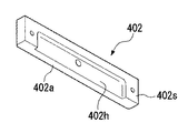
エアパッド45に替えて、図6A,Bに示すエアパッド400を用いることもできる。図6Aはエアパッド400を軸受面側から見た斜視図、図6Bはスロット部材402の斜視図である。
Instead of the
エアパッド400は、スロット絞りを有する。スロット絞りとは、極めて狭い隙間(5〜20μm程度)の流路により、流体抵抗を高くして、強い絞り効果を得るものである。高い剛性が得られ、しかも軸受面に溝がないためにニューマチックハンマー現象に対しても安定性が高いという特徴がある。しかしながら、狭い隙間を形成が困難であり、量産性に劣るという問題がある。
The
そこで、エアパッド400は、このような問題を解決するために、軸受面401aを有する軸受部材401の側面401sにスロット部材402をボルト等で取り付けることにより、スロット絞りを形成している。すなわち、軸受部材401の側面401sは平坦に形成され、一方、スロット部材402の側面402sには5〜20μm程度の掘り込み402h(図6B参照)が形成される。そして、軸受部材401の側面401sとスロット部材402の側面402sとを密着固定することにより、軸受部材401の軸受面401aとスロット部材402の軸受面402aとの間にスロット絞りを形成している(図6A参照)。このように、軸受部材401の四方の側面401sにそれぞれスロット部材402を取り付けて各スロット絞り部に流体(気体)を供給することにより、エアパッド400が構成される。
Therefore, in order to solve such a problem, the
エアパッド400は、軸受部材401にスロット部材402を取り付けることにより、スロット絞りを形成しているので、スロット絞りが分解可能となり、絞り部分のメンテナンスを容易に行うことができる。また、異なる掘り込み量を有するスロット部材に交換することにより、スロット幅を変化させて、エアパッド400の剛性を変化させることも可能となる。
Since the
このようなエアパッド400をXYテーブル43の下面に複数の配置することにより、ウエハ定盤44上にXYテーブル43を非接触に、しかも高剛性に支持することができる。
By arranging a plurality of
また、本発明は、例えば、特開平10−163099号公報、特開平10−214783号公報及びこれらに対応する米国特許6,400,441号と、特表2000−505958号公報及びこれに対応する米国特許5,969,441号及び米国特許6,262,796号公報に開示されているように、ウエハ等の被処理基板を別々に載置してXY方向に独立に移動可能な複数のステージを備えた露光装置にも適用できる。本国際出願で指定した指定国(又は選択した選択国)の国内法令で許される限りにおいて、上記公報または米国特許における開示を援用して本明細書の一部とする。 Further, the present invention corresponds to, for example, Japanese Patent Application Laid-Open No. 10-163099, Japanese Patent Application Laid-Open No. 10-214783, and corresponding US Pat. No. 6,400,441, and Japanese Translation of PCT International Publication No. 2000-505958 and the like. As disclosed in U.S. Pat. No. 5,969,441 and U.S. Pat. No. 6,262,796, a plurality of stages on which substrates to be processed such as wafers are separately placed and can be moved independently in the XY directions The present invention can also be applied to an exposure apparatus provided with To the extent permitted by national legislation of the designated country (or selected selected country) designated in this international application, the disclosure in the above publication or US patent is incorporated herein by reference.
また、本発明は、ウエハ等の被処理基板を保持して移動可能な露光ステージと、各種の計測部材やセンサを備えた計測ステージとを備えた露光装置にも適用可能である。このような露光装置は、例えば、特開平11−135400号公報に開示されている。本国際出願で指定した指定国(又は選択した選択国)の国内法令で許される限りにおいて、上記公報における開示を援用して本明細書の記載の一部とする。 The present invention is also applicable to an exposure apparatus including an exposure stage that can move while holding a substrate to be processed such as a wafer, and a measurement stage that includes various measurement members and sensors. Such an exposure apparatus is disclosed, for example, in JP-A-11-135400. To the extent permitted by national laws and regulations of the designated country (or selected selected country) designated in this international application, the disclosure in the above publication is incorporated as a part of the description of this specification.
上述の実施形態においては、光透過性の基板上に所定の遮光パターン(または位相パターン・減光パターン)を形成した光透過型マスク、あるいは光反射性の基板上に所定の反射パターン光反射型マスクを用いたが、それらに限定されるものではない。例えば、そのようなマスクに代えて、露光すべきパターンの電子データに基づいて透過パターンまたは反射パターン、あるいは発光パターンを形成する電子マスク(光学系の一種とする)を用いるようにしても良い。このような電子マスクは、例えば米国特許第6,778,257号公報に開示されている。本国際出願で指定した指定国(又は選択した選択国)の国内法令で許される限りにおいて、上記各米国特許における開示を援用して本明細書の記載の一部とする。なお、上述の電子マスクとは、非発光型画像表示素子と自発光型画像表示素子との双方を含む概念である。 In the above-described embodiment, a light transmissive mask in which a predetermined light-shielding pattern (or phase pattern / dimming pattern) is formed on a light transmissive substrate, or a predetermined reflective pattern light reflective type on a light reflective substrate. Although a mask was used, it is not limited to them. For example, instead of such a mask, an electronic mask (which is a kind of optical system) that forms a transmission pattern, a reflection pattern, or a light emission pattern based on electronic data of a pattern to be exposed may be used. Such an electronic mask is disclosed in, for example, US Pat. No. 6,778,257. To the extent permitted by national laws of the designated country (or selected selected country) designated in this international application, the disclosure in each of the above US patents is incorporated herein by reference. Note that the above-described electronic mask is a concept including both a non-light-emitting image display element and a self-light-emitting image display element.
また、例えば、2光束干渉露光と呼ばれているような、複数の光束の干渉によって生じる干渉縞を基板に露光するような露光装置にも適用することができる。そのような露光方法及び露光装置は、例えば、国際公開第01/35168号パンフレットに開示されている。本国際出願で指定した指定国(又は選択した選択国)の国内法令で許される限りにおいて、上記パンフレットにおける開示を援用して本明細書の記載の一部とする。 Further, for example, the present invention can also be applied to an exposure apparatus that exposes a substrate with interference fringes caused by interference of a plurality of light beams, which is called two-beam interference exposure. Such an exposure method and exposure apparatus are disclosed in, for example, WO 01/35168. To the extent permitted by national laws and regulations of the designated country (or selected selected country) designated in this international application, the disclosure in the above pamphlet is incorporated as a part of the description of this specification.
また、本発明は、投影光学系PLと基板(ウエハ)Wとの間を液体で満たして露光を行う液浸露光装置にも適用可能である。そのような液浸露光装置としては、例えば、投影光学系30と基板Wとの間を局所的に液体で満たす方式として、国際公開第2004/053958号パンフレットに開示されているものが知られている。本国際出願で指定した指定国(又は選択した選択国)の国内法令で許される限りにおいて、上記パンフレットにおける開示を援用して本明細書の記載の一部とする。また、本発明は、露光対象の基板(ウエハ)Wを保持したステージを液槽の中で移動させる液浸露光装置や、ステージ上に所定深さの液体槽を形成しその中に基板Wを保持する液浸露光装置にも適用可能である。露光対象の基板を保持したステージを液槽の中で移動させる液浸露光装置の構造及び露光動作については、例えば、特開平6−124873号公報に、ステージ上に所定深さの液体槽を形成してその中に基板を保持する液浸露光装置については、例えば特開平10−303114号公報や米国特許第5,825,043号にそれぞれ開示されている。本国際出願で指定した指定国(又は選択した選択国)の国内法令で許される限りにおいて、上記公報または米国特許における開示を援用して本明細書の記載の一部とする。
The present invention is also applicable to an immersion exposure apparatus that performs exposure by filling a space between the projection optical system PL and the substrate (wafer) W with a liquid. As such an immersion exposure apparatus, for example, a system disclosed in International Publication No. 2004/053958 is known as a system for locally filling the space between the projection
また、投影光学系30の終端光学部材の射出側の光路空間を液体(純水)で満たして基板(ウエハ)Wを露光する構成に限るものではなく、国際公開第2004/019128号パンフレットに開示されているように、投影光学系の終端光学部材の入射側の光路空間も液体(純水)で満たすようにしてもよい。本国際出願で指定した指定国(又は選択した選択国)の国内法令で許される限りにおいて、上記パンフレットにおける開示を援用して本明細書の記載の一部とする。
Further, the present invention is not limited to the configuration in which the optical path space on the exit side of the terminal optical member of the projection
また、前述した実施形態ではステップ・アンド・リピート方式の露光装置を例に挙げて説明したが、ステップ・アンド・スキャン方式の露光装置にも本発明を適用することができる。更に、本発明は半導体素子の製造に用いられる露光装置だけではなく、液晶表示素子(LCD)等を含むディスプレイの製造に用いられてデバイスパターンをガラスプレート上へ転写する露光装置、薄膜磁気ヘッドの製造に用いられてデバイスパターンをセラミックウエハ上へ転写する露光装置、及びCCD等の撮像素子の製造に用いられる露光装置等にも適用することができる。更には、光露光装置、EUV露光装置、X線露光装置、及び電子線露光装置などで使用されるレチクル又はマスクを製造するために、ガラス基板又はシリコンウエハなどに回路パターンを転写する露光装置にも本発明を適用できる。ここで、DUV(遠紫外)光やVUV(真空紫外)光などを用いる露光装置では一般的に透過型レチクルが用いられ、レチクル基板としては石英ガラス、フッ素がドープされた石英ガラス、蛍石、フッ化マグネシウム、又は水晶などが用いられる。また、プロキシミティ方式のX線露光装置、又は電子線露光装置などでは透過型マスク(ステンシルマスク、メンブレンマスク)が用いられ、マスク基板としてはシリコンウエハなどが用いられる。 In the above-described embodiment, the step-and-repeat type exposure apparatus has been described as an example. However, the present invention can also be applied to a step-and-scan type exposure apparatus. Furthermore, the present invention is not limited to an exposure apparatus used for manufacturing a semiconductor element, but also used for manufacturing a display including a liquid crystal display element (LCD) and the like. The present invention can also be applied to an exposure apparatus that is used for manufacturing and transfers a device pattern onto a ceramic wafer, and an exposure apparatus that is used to manufacture an image sensor such as a CCD. Furthermore, in an exposure apparatus that transfers a circuit pattern onto a glass substrate or a silicon wafer in order to manufacture a reticle or mask used in an optical exposure apparatus, EUV exposure apparatus, X-ray exposure apparatus, electron beam exposure apparatus, or the like. The present invention can also be applied. Here, in an exposure apparatus using DUV (far ultraviolet) light, VUV (vacuum ultraviolet) light, or the like, a transmission type reticle is generally used. As a reticle substrate, quartz glass, fluorine-doped quartz glass, fluorite, Magnesium fluoride or quartz is used. Further, in a proximity type X-ray exposure apparatus or an electron beam exposure apparatus, a transmission mask (stencil mask, membrane mask) is used, and a silicon wafer or the like is used as a mask substrate.
次に、本発明の実施形態による露光装置及び露光方法をリソグラフィ工程で使用したマイクロデバイスの製造方法の実施形態について説明する。図7は、マイクロデバイス(ICやLSI等の半導体チップ、液晶パネル、CCD、薄膜磁気ヘッド、マイクロマシン等)の製造例のフローチャートを示す図である。図7に示すように、まず、ステップS10(設計ステップ)において、マイクロデバイスの機能・性能設計(例えば、半導体デバイスの回路設計等)を行い、その機能を実現するためのパターン設計を行う。引き続き、ステップS11(マスク製作ステップ)において、設計した回路パターンを形成したマスク(レチクル)を製作する。一方、ステップS12(ウエハ製造ステップ)において、シリコン等の材料を用いてウエハを製造する。 Next, an embodiment of a manufacturing method of a micro device using the exposure apparatus and the exposure method according to the embodiment of the present invention in the lithography process will be described. FIG. 7 is a flowchart showing a manufacturing example of a micro device (a semiconductor chip such as an IC or LSI, a liquid crystal panel, a CCD, a thin film magnetic head, a micro machine, etc.). As shown in FIG. 7, first, in step S10 (design step), a function / performance design (for example, circuit design of a semiconductor device) of a micro device is performed, and a pattern design for realizing the function is performed. Subsequently, in step S11 (mask manufacturing step), a mask (reticle) on which the designed circuit pattern is formed is manufactured. On the other hand, in step S12 (wafer manufacturing step), a wafer is manufactured using a material such as silicon.
次に、ステップS13(ウエハ処理ステップ)において、ステップS10〜ステップS12で用意したマスクとウエハを使用して、後述するように、リソグラフィ技術等によってウエハ上に実際の回路等を形成する。次いで、ステップS14(デバイス組立ステップ)において、ステップS13で処理されたウエハを用いてデバイス組立を行う。このステップS14には、ダイシング工程、ボンティング工程、及びパッケージング工程(チップ封入)等の工程が必要に応じて含まれる。最後に、ステップS15(検査ステップ)において、ステップS14で作製されたマイクロデバイスの動作確認テスト、耐久性テスト等の検査を行う。こうした工程を経た後にマイクロデバイスが完成し、これが出荷される。 Next, in step S13 (wafer processing step), using the mask and wafer prepared in steps S10 to S12, an actual circuit or the like is formed on the wafer by lithography or the like, as will be described later. Next, in step S14 (device assembly step), device assembly is performed using the wafer processed in step S13. This step S14 includes processes such as a dicing process, a bonding process, and a packaging process (chip encapsulation) as necessary. Finally, in step S15 (inspection step), inspections such as an operation confirmation test and a durability test of the microdevice manufactured in step S14 are performed. After these steps, the microdevice is completed and shipped.
図8は、半導体デバイスの場合におけるステップS13の詳細工程の一例を示す図である。 FIG. 8 is a diagram illustrating an example of a detailed process of step S13 in the case of a semiconductor device.
ステップS21(酸化ステップ)おいては、ウエハの表面を酸化させる。ステップS22(CVDステップ)においては、ウエハ表面に絶縁膜を形成する。ステップS23(電極形成ステップ)においては、ウエハ上に電極を蒸着によって形成する。ステップS24(イオン打込みステップ)においては、ウエハにイオンを打ち込む。以上のステップS21〜ステップS24のそれぞれは、ウエハ処理の各段階の前処理工程を構成しており、各段階において必要な処理に応じて選択されて実行される。 In step S21 (oxidation step), the surface of the wafer is oxidized. In step S22 (CVD step), an insulating film is formed on the wafer surface. In step S23 (electrode formation step), an electrode is formed on the wafer by vapor deposition. In step S24 (ion implantation step), ions are implanted into the wafer. Each of the above steps S21 to S24 constitutes a pre-processing process at each stage of the wafer processing, and is selected and executed according to a necessary process at each stage.
ウエハプロセスの各段階において、上述の前処理工程が終了すると、以下のようにして後処理工程が実行される。この後処理工程では、まず、ステップS25(レジスト形成ステップ)において、ウエハに感光剤を塗布する。引き続き、ステップS26(露光ステップ)において、上で説明したリソグラフィシステム(露光装置)及び露光方法によってマスクの回路パターンをウエハに転写する。次に、ステップS27(現像ステップ)においては露光されたウエハを現像し、ステップS28(エッチングステップ)において、レジストが残存している部分以外の部分の露出部材をエッチングにより取り去る。そして、ステップS29(レジスト除去ステップ)において、エッチングが済んで不要となったレジストを取り除く。これらの前処理工程と後処理工程とを繰り返し行うことによって、ウエハ上に多重に回路パターンが形成される。 At each stage of the wafer process, when the above pre-process is completed, the post-process is executed as follows. In this post-processing process, first, in step S25 (resist formation step), a photosensitive agent is applied to the wafer. Subsequently, in step S26 (exposure step), the circuit pattern of the mask is transferred to the wafer by the lithography system (exposure apparatus) and the exposure method described above. Next, in step S27 (development step), the exposed wafer is developed, and in step S28 (etching step), exposed members other than the portion where the resist remains are removed by etching. In step S29 (resist removal step), the resist that has become unnecessary after the etching is removed. By repeatedly performing these pre-processing steps and post-processing steps, multiple circuit patterns are formed on the wafer.
また、半導体素子等のマイクロデバイスだけではなく、光露光装置、EUV露光装置、X線露光装置、及び電子線露光装置等で使用されるレチクル又はマスクを製造するために、マザーレチクルからガラス基板やシリコンウエハ等ヘ回路パターンを転写する露光装置にも本発明を適用できる。ここで、DUV(深紫外)やVUV(真空紫外)光等を用いる露光装置では、一般的に透過型レチクルが用いられ、レチクル基板としては石英ガラス、フッ素がドープされた石英ガラス、蛍石、フッ化マグネシウム、又は水晶等が用いられる。また、プロキシミティ方式のX線露光装置や電子線露光装置等では、透過型マスク(ステンシルマスク、メンブレンマスク)が用いられ、マスク基板としてはシリコンウエハ等が用いられる。なお、このような露光装置は、国際公開第99/34255号、国際公開第99/50712号、および国際公開第99/66370号の各パンフレット、及び特開平11−194479号、特開2000−12453号、特開2000−29202号の各公報に開示されている。本国際出願で指定した指定国(又は選択した選択国)の国内法令で許される限りにおいて、上記パンフレット及び公報における開示を援用して本明細書の一部とする。 Further, in order to manufacture reticles or masks used in not only microdevices such as semiconductor elements but also light exposure apparatuses, EUV exposure apparatuses, X-ray exposure apparatuses, electron beam exposure apparatuses, etc., from mother reticles to glass substrates and The present invention can also be applied to an exposure apparatus that transfers a circuit pattern to a silicon wafer or the like. Here, in an exposure apparatus using DUV (deep ultraviolet), VUV (vacuum ultraviolet) light, or the like, a transmission type reticle is generally used. As a reticle substrate, quartz glass, fluorine-doped quartz glass, fluorite, Magnesium fluoride or quartz is used. In proximity-type X-ray exposure apparatuses, electron beam exposure apparatuses, and the like, a transmissive mask (stencil mask, membrane mask) is used, and a silicon wafer or the like is used as a mask substrate. Such exposure apparatuses include pamphlets of International Publication No. 99/34255, International Publication No. 99/50712, and International Publication No. 99/66370, and Japanese Patent Application Laid-Open Nos. 11-194479 and 2000-12453. And JP-A-2000-29202. To the extent permitted by national laws and regulations of the designated country (or selected selected country) designated in this international application, the disclosure in the above pamphlets and gazettes is incorporated and made a part of this specification.
Claims (18)
前記シリンダ部の内側に設けられて第1方向に移動可能なピストン部と、
前記シリンダ部の内壁と前記ピストン部の外壁との間の少なくとも一部に形成された流体軸受と、を備え、
前記シリンダ部と前記ピストン部により生成される付勢力によって被支持部材を支持部材に対して前記第1方向に支持する支持装置であって、
前記流体軸受と前記シリンダ部の内部に、それぞれ独立して流体を供給することを特徴とする支持装置。A cylinder part;
A piston portion provided inside the cylinder portion and movable in a first direction;
A fluid bearing formed on at least a part between the inner wall of the cylinder part and the outer wall of the piston part,
A support device for supporting a supported member in a first direction with respect to a support member by an urging force generated by the cylinder portion and the piston portion;
A support device, wherein fluid is independently supplied to the fluid bearing and the cylinder portion.
前記第1供給装置から供給される流体の圧力と、前記第2供給装置から供給される流体の圧力とが異なることを特徴とする請求項1に記載の支持装置。A first supply device for supplying fluid to the inside of the cylinder part, and a second supply device for supplying fluid to the fluid bearing,
The support device according to claim 1, wherein the pressure of the fluid supplied from the first supply device is different from the pressure of the fluid supplied from the second supply device.
前記第2供給装置は、前記多孔質体に流体を供給することを特徴とする請求項2から請求項8のうちいずれか一項に記載の支持装置。The fluid bearing has a porous body provided on at least one of an inner wall of the cylinder part and an outer wall of the piston part,
The support device according to any one of claims 2 to 8, wherein the second supply device supplies a fluid to the porous body.
前記ピストン部と前記中間部材との間に形成された第2流体軸受とを備え、
前記第2流体軸受は、前記第1供給装置と前記第2供給装置の少なくとも一方から流体を供給されることを特徴とする請求項2から請求項9のうちいずれか一項に記載の支持装置。An intermediate member that is disposed at one end of the piston portion and can be inclined with respect to a plane that intersects the first direction;
A second fluid bearing formed between the piston portion and the intermediate member;
The support device according to any one of claims 2 to 9, wherein the second fluid bearing is supplied with fluid from at least one of the first supply device and the second supply device. .
前記支持部材又は前記被支持部材と前記支持面との間で前記第1方向と交差する方向に対して相対移動が可能であることを特徴とする請求項10に記載の支持装置。The intermediate member has a support surface that supports the support member or the supported member,
The support device according to claim 10, wherein relative movement is possible between the support member or the supported member and the support surface with respect to a direction intersecting the first direction.
前記支持装置が、請求項1から請求項14のうちいずれか一項に記載の支持装置であり、
前記第2部材が前記被支持部材の少なくとも一部を含むことを特徴とするステージ装置。In a stage apparatus comprising: a first member; and a second member movably supported with respect to the first member by at least one supporting device.
The support device is the support device according to any one of claims 1 to 14,
The stage apparatus, wherein the second member includes at least a part of the supported member.
請求項13に記載の支持装置を備え、前記支持装置によって前記ベース上に支持されていることを特徴とするステージ装置。A stage device movable on a base having a guide surface,
A stage apparatus comprising the support apparatus according to claim 13, wherein the stage apparatus is supported on the base by the support apparatus.
前記マスクステージと前記基板ステージの少なくとも一方に、請求項15又は請求項16に記載のステージ装置を用いることを特徴とする露光装置。In an exposure apparatus having a mask stage for holding a mask and a substrate stage for holding a substrate, and exposing the pattern formed on the mask to the substrate,
An exposure apparatus using the stage apparatus according to claim 15 or 16 for at least one of the mask stage and the substrate stage.
Applications Claiming Priority (3)
| Application Number | Priority Date | Filing Date | Title |
|---|---|---|---|
| JP2004215434 | 2004-07-23 | ||
| JP2004215434 | 2004-07-23 | ||
| PCT/JP2005/013496 WO2006009254A1 (en) | 2004-07-23 | 2005-07-22 | Support device, stage device, exposure device, and device manufacturing method |
Publications (1)
| Publication Number | Publication Date |
|---|---|
| JPWO2006009254A1 true JPWO2006009254A1 (en) | 2008-05-01 |
Family
ID=35785361
Family Applications (1)
| Application Number | Title | Priority Date | Filing Date |
|---|---|---|---|
| JP2006529300A Withdrawn JPWO2006009254A1 (en) | 2004-07-23 | 2005-07-22 | Support apparatus, stage apparatus, exposure apparatus, and device manufacturing method |
Country Status (5)
| Country | Link |
|---|---|
| US (1) | US20080013060A1 (en) |
| EP (1) | EP1811526A4 (en) |
| JP (1) | JPWO2006009254A1 (en) |
| KR (1) | KR20070039926A (en) |
| WO (1) | WO2006009254A1 (en) |
Families Citing this family (28)
| Publication number | Priority date | Publication date | Assignee | Title |
|---|---|---|---|---|
| TWI405041B (en) | 2004-12-01 | 2013-08-11 | 尼康股份有限公司 | Stage device and exposure device |
| US8693006B2 (en) | 2005-06-28 | 2014-04-08 | Nikon Corporation | Reflector, optical element, interferometer system, stage device, exposure apparatus, and device fabricating method |
| EP1744215B1 (en) * | 2005-07-16 | 2012-09-12 | Integrated Dynamics Engineering GmbH | Supporting device for supporting vibration sensitive components |
| EP1918983A4 (en) * | 2005-08-05 | 2010-03-31 | Nikon Corp | PLATINUM APPARATUS AND EXPOSURE APPARATUS |
| KR101419196B1 (en) | 2006-09-29 | 2014-07-15 | 가부시키가이샤 니콘 | Exposure apparatus, exposure method, and device manufacturing method |
| US7760331B2 (en) * | 2007-02-20 | 2010-07-20 | Electro Scientific Industries, Inc. | Decoupled, multiple stage positioning system |
| KR101547784B1 (en) * | 2007-03-05 | 2015-08-26 | 가부시키가이샤 니콘 | Moving body apparatus, apparatus for forming pattern, method of forming pattern, method of producing device, method of producing moving body apparatus, and method of driving moving body |
| US7607647B2 (en) * | 2007-03-20 | 2009-10-27 | Kla-Tencor Technologies Corporation | Stabilizing a substrate using a vacuum preload air bearing chuck |
| KR100975646B1 (en) * | 2007-08-13 | 2010-08-17 | 주식회사 시스넥스 | Hydrogen Vapor Deposition Machine |
| US20090088682A1 (en) * | 2007-09-28 | 2009-04-02 | Seattle Medical Technologies | Wearable infusion device |
| JP5319154B2 (en) * | 2008-04-18 | 2013-10-16 | 住友重機械工業株式会社 | Stage equipment |
| JP5200745B2 (en) * | 2008-08-05 | 2013-06-05 | 日本精工株式会社 | Three-dimensional positioning device and atomic force microscope equipped with the same |
| US8699001B2 (en) * | 2009-08-20 | 2014-04-15 | Nikon Corporation | Object moving apparatus, object processing apparatus, exposure apparatus, object inspecting apparatus and device manufacturing method |
| US20110053092A1 (en) * | 2009-08-20 | 2011-03-03 | Nikon Corporation | Object processing apparatus, exposure apparatus and exposure method, and device manufacturing method |
| US20110042874A1 (en) * | 2009-08-20 | 2011-02-24 | Nikon Corporation | Object processing apparatus, exposure apparatus and exposure method, and device manufacturing method |
| CN102630334A (en) * | 2009-09-28 | 2012-08-08 | 株式会社尼康 | Pressurization module, pressurization device, and substrate bonding device |
| KR102181614B1 (en) * | 2010-09-07 | 2020-11-23 | 가부시키가이샤 니콘 | Exposure apparatus, movable body apparatus, flat-panel display manufacturing method, and device manufacturing method |
| US8988655B2 (en) * | 2010-09-07 | 2015-03-24 | Nikon Corporation | Exposure apparatus, movable body apparatus, flat-panel display manufacturing method, and device manufacturing method |
| US8598538B2 (en) | 2010-09-07 | 2013-12-03 | Nikon Corporation | Movable body apparatus, object processing device, exposure apparatus, flat-panel display manufacturing method, and device manufacturing method |
| JP5590187B1 (en) * | 2013-05-20 | 2014-09-17 | 日本精工株式会社 | Table device, transfer device, and semiconductor manufacturing device |
| JP5541398B1 (en) | 2013-07-02 | 2014-07-09 | 日本精工株式会社 | Table device and transfer device |
| JP5594404B1 (en) | 2013-07-02 | 2014-09-24 | 日本精工株式会社 | Table device, transfer device, semiconductor manufacturing device, and flat panel display manufacturing device |
| EP3181944B1 (en) * | 2015-12-16 | 2023-04-26 | Integrated Dynamics Engineering GmbH | Vibration isolator with a vertically active pneumatic spring |
| TWI773710B (en) | 2016-12-30 | 2022-08-11 | 荷蘭商Asml荷蘭公司 | Adjustment assembly and substrate exposure system comprising such an adjustment assembly |
| US10048599B2 (en) * | 2016-12-30 | 2018-08-14 | Mapper Lithography Ip B.V. | Adjustment assembly and substrate exposure system comprising such an adjustment assembly |
| US10254659B1 (en) * | 2017-09-27 | 2019-04-09 | Wuhan China Star Optoelectronics Technology Co., Ltd | Exposure apparatus and method for exposure of transparent substrate |
| DE102018201845A1 (en) * | 2018-02-06 | 2019-08-08 | Thyssenkrupp Ag | Bearing arrangement with self-adjusting and interference-insensitive force elements |
| JP7583425B2 (en) * | 2020-04-13 | 2024-11-14 | 貴雄 岡部 | Stage device and semiconductor manufacturing device |
Family Cites Families (18)
| Publication number | Priority date | Publication date | Assignee | Title |
|---|---|---|---|---|
| US5825043A (en) * | 1996-10-07 | 1998-10-20 | Nikon Precision Inc. | Focusing and tilting adjustment system for lithography aligner, manufacturing apparatus or inspection apparatus |
| JP3044196B2 (en) * | 1996-11-11 | 2000-05-22 | ファナック株式会社 | Balance mechanism of driven body |
| SG102627A1 (en) * | 1996-11-28 | 2004-03-26 | Nikon Corp | Lithographic device |
| WO1998028665A1 (en) * | 1996-12-24 | 1998-07-02 | Koninklijke Philips Electronics N.V. | Two-dimensionally balanced positioning device with two object holders, and lithographic device provided with such a positioning device |
| EP0900412B1 (en) * | 1997-03-10 | 2005-04-06 | ASML Netherlands B.V. | Lithographic apparatus comprising a positioning device having two object holders |
| US6144442A (en) * | 1997-10-23 | 2000-11-07 | U.S. Philips Corp | Pneumatic support device with a controlled gas supply, and lithographic device provided with such a support device |
| JP3811284B2 (en) * | 1998-03-18 | 2006-08-16 | シーケーディ株式会社 | Air bearing cylinder, rod for air bearing cylinder and manifold cylinder |
| EP0973067A3 (en) * | 1998-07-17 | 2001-10-24 | ASM Lithography B.V. | Positioning device and lithographic projection apparatus comprising such a device |
| TWI242113B (en) * | 1998-07-17 | 2005-10-21 | Asml Netherlands Bv | Positioning device and lithographic projection apparatus comprising such a device |
| US6607157B1 (en) * | 1999-07-14 | 2003-08-19 | Keltech Engineering, Inc. | Air bearing system with an air cylinder web dancer system or idler rolls |
| KR100699241B1 (en) * | 1999-09-20 | 2007-03-27 | 가부시키가이샤 니콘 | Parallel link mechanism, exposure apparatus and manufacturing method thereof, and device manufacturing method |
| TW509823B (en) * | 2000-04-17 | 2002-11-11 | Asml Netherlands Bv | Lithographic apparatus, device manufacturing method, and device manufactured thereby |
| EP1160628B1 (en) | 2000-06-02 | 2007-07-18 | ASML Netherlands B.V. | Lithographic projection apparatus with a supporting assembly |
| DE60129377T2 (en) * | 2000-06-02 | 2008-03-20 | Asml Netherlands B.V. | Lithographic projection apparatus with a support arrangement |
| US6538720B2 (en) * | 2001-02-28 | 2003-03-25 | Silicon Valley Group, Inc. | Lithographic tool with dual isolation system and method for configuring the same |
| TW529172B (en) * | 2001-07-24 | 2003-04-21 | Asml Netherlands Bv | Imaging apparatus |
| US6756751B2 (en) * | 2002-02-15 | 2004-06-29 | Active Precision, Inc. | Multiple degree of freedom substrate manipulator |
| JP3825737B2 (en) * | 2002-10-24 | 2006-09-27 | 住友重機械工業株式会社 | Precision positioning device and processing machine using the same |
-
2005
- 2005-07-22 JP JP2006529300A patent/JPWO2006009254A1/en not_active Withdrawn
- 2005-07-22 EP EP05766366A patent/EP1811526A4/en not_active Withdrawn
- 2005-07-22 WO PCT/JP2005/013496 patent/WO2006009254A1/en not_active Ceased
- 2005-07-22 US US11/632,826 patent/US20080013060A1/en not_active Abandoned
- 2005-07-22 KR KR1020077001436A patent/KR20070039926A/en not_active Withdrawn
Also Published As
| Publication number | Publication date |
|---|---|
| US20080013060A1 (en) | 2008-01-17 |
| EP1811526A4 (en) | 2008-04-16 |
| KR20070039926A (en) | 2007-04-13 |
| WO2006009254A1 (en) | 2006-01-26 |
| EP1811526A1 (en) | 2007-07-25 |
Similar Documents
| Publication | Publication Date | Title |
|---|---|---|
| JPWO2006009254A1 (en) | Support apparatus, stage apparatus, exposure apparatus, and device manufacturing method | |
| US6894449B2 (en) | Vibration control device, stage device and exposure apparatus | |
| JP4028969B2 (en) | Lithographic projection apparatus, support assembly, and device manufacturing method | |
| JP2009117877A (en) | Exposure apparatus and device manufacturing method | |
| JP6551762B2 (en) | Mobile body apparatus, exposure apparatus, method of manufacturing flat panel display, and method of manufacturing device | |
| KR20040007448A (en) | Holding device, holding method, exposure device, and device manufacturing method | |
| JP2006086442A (en) | Stage apparatus and exposure apparatus | |
| JPWO2006022200A1 (en) | Stage apparatus and exposure apparatus | |
| JP7472958B2 (en) | MOVING BODY APPARATUS, EXPOSURE APPARATUS, AND DEVICE MANUFACTURING METHOD | |
| TW200302507A (en) | Stage device and exposure device | |
| KR20070011347A (en) | Gas spring device, dustproof device, stage device and exposure device | |
| JP5578485B2 (en) | MOBILE DEVICE, EXPOSURE APPARATUS, AND DEVICE MANUFACTURING METHOD | |
| JP2006040927A (en) | Support apparatus, stage apparatus, exposure apparatus, and device manufacturing method | |
| JP5082929B2 (en) | Fluid bearing, stage apparatus, exposure apparatus, and device manufacturing method | |
| JP2006066589A (en) | Stage apparatus and exposure apparatus, device manufacturing method, and stage apparatus driving method | |
| JP2009065043A (en) | Object suspension apparatus, exposure apparatus, and suspension support method | |
| JP2005236087A (en) | Exposure equipment | |
| JPWO2006001282A1 (en) | Positioning apparatus, positioning method, exposure apparatus, exposure method, and device manufacturing method | |
| JP2009049119A (en) | Base member, manufacturing method thereof, stage apparatus, and exposure apparatus | |
| JP2004169784A (en) | Bearing device, stage device and exposure device | |
| JP2006140399A (en) | Positioning apparatus, exposure apparatus, device manufacturing method, and stage apparatus maintenance method | |
| JP2005331009A (en) | Vibration isolator and exposure apparatus | |
| JP2006066687A (en) | Temperature control method, stage apparatus, exposure apparatus, and device manufacturing method | |
| JP2009016386A (en) | Positioning apparatus, stage apparatus, exposure apparatus, and device manufacturing method | |
| JP2005236078A (en) | Exposure equipment |
Legal Events
| Date | Code | Title | Description |
|---|---|---|---|
| A621 | Written request for application examination |
Free format text: JAPANESE INTERMEDIATE CODE: A621 Effective date: 20080701 |
|
| A761 | Written withdrawal of application |
Free format text: JAPANESE INTERMEDIATE CODE: A761 Effective date: 20100609 |