JPWO2005048325A1 - Stage driving method, stage apparatus, and exposure apparatus - Google Patents
Stage driving method, stage apparatus, and exposure apparatus Download PDFInfo
- Publication number
- JPWO2005048325A1 JPWO2005048325A1 JP2005515422A JP2005515422A JPWO2005048325A1 JP WO2005048325 A1 JPWO2005048325 A1 JP WO2005048325A1 JP 2005515422 A JP2005515422 A JP 2005515422A JP 2005515422 A JP2005515422 A JP 2005515422A JP WO2005048325 A1 JPWO2005048325 A1 JP WO2005048325A1
- Authority
- JP
- Japan
- Prior art keywords
- stage
- wafer
- guide portion
- axis
- driving
- Prior art date
- Legal status (The legal status is an assumption and is not a legal conclusion. Google has not performed a legal analysis and makes no representation as to the accuracy of the status listed.)
- Pending
Links
Images


Classifications
-
- G—PHYSICS
- G03—PHOTOGRAPHY; CINEMATOGRAPHY; ANALOGOUS TECHNIQUES USING WAVES OTHER THAN OPTICAL WAVES; ELECTROGRAPHY; HOLOGRAPHY
- G03F—PHOTOMECHANICAL PRODUCTION OF TEXTURED OR PATTERNED SURFACES, e.g. FOR PRINTING, FOR PROCESSING OF SEMICONDUCTOR DEVICES; MATERIALS THEREFOR; ORIGINALS THEREFOR; APPARATUS SPECIALLY ADAPTED THEREFOR
- G03F7/00—Photomechanical, e.g. photolithographic, production of textured or patterned surfaces, e.g. printing surfaces; Materials therefor, e.g. comprising photoresists; Apparatus specially adapted therefor
- G03F7/70—Microphotolithographic exposure; Apparatus therefor
- G03F7/70691—Handling of masks or workpieces
- G03F7/70733—Handling masks and workpieces, e.g. exchange of workpiece or mask, transport of workpiece or mask
-
- G—PHYSICS
- G03—PHOTOGRAPHY; CINEMATOGRAPHY; ANALOGOUS TECHNIQUES USING WAVES OTHER THAN OPTICAL WAVES; ELECTROGRAPHY; HOLOGRAPHY
- G03F—PHOTOMECHANICAL PRODUCTION OF TEXTURED OR PATTERNED SURFACES, e.g. FOR PRINTING, FOR PROCESSING OF SEMICONDUCTOR DEVICES; MATERIALS THEREFOR; ORIGINALS THEREFOR; APPARATUS SPECIALLY ADAPTED THEREFOR
- G03F7/00—Photomechanical, e.g. photolithographic, production of textured or patterned surfaces, e.g. printing surfaces; Materials therefor, e.g. comprising photoresists; Apparatus specially adapted therefor
- G03F7/70—Microphotolithographic exposure; Apparatus therefor
- G03F7/70691—Handling of masks or workpieces
- G03F7/70716—Stages
- G03F7/70725—Stages control
-
- G—PHYSICS
- G03—PHOTOGRAPHY; CINEMATOGRAPHY; ANALOGOUS TECHNIQUES USING WAVES OTHER THAN OPTICAL WAVES; ELECTROGRAPHY; HOLOGRAPHY
- G03F—PHOTOMECHANICAL PRODUCTION OF TEXTURED OR PATTERNED SURFACES, e.g. FOR PRINTING, FOR PROCESSING OF SEMICONDUCTOR DEVICES; MATERIALS THEREFOR; ORIGINALS THEREFOR; APPARATUS SPECIALLY ADAPTED THEREFOR
- G03F7/00—Photomechanical, e.g. photolithographic, production of textured or patterned surfaces, e.g. printing surfaces; Materials therefor, e.g. comprising photoresists; Apparatus specially adapted therefor
- G03F7/70—Microphotolithographic exposure; Apparatus therefor
- G03F7/70691—Handling of masks or workpieces
- G03F7/70758—Drive means, e.g. actuators, motors for long- or short-stroke modules or fine or coarse driving
Landscapes
- Physics & Mathematics (AREA)
- General Physics & Mathematics (AREA)
- Exposure And Positioning Against Photoresist Photosensitive Materials (AREA)
Abstract
第1方向に延びたガイド部に沿ってステージを定盤の表面で駆動するステージ駆動方法であって、前記第1方向へ前記ステージを駆動する際の推力に応じて、前記ガイド部を前記表面と直交する軸周りに回転させるステップを含む。ガイド部にモーメント負荷が掛かった場合でもギャップつぶれを生じさせず、安全性を高めることができる。A stage driving method for driving a stage on a surface of a surface plate along a guide portion extending in a first direction, wherein the guide portion is moved to the surface according to a thrust force when the stage is driven in the first direction. And rotating around an axis orthogonal to. Even when a moment load is applied to the guide portion, the gap is not crushed and safety can be improved.
Description
本発明は、ステージ駆動方法及びステージ装置並びに露光装置に関し、特に、片持ち状態で支持されたステージを駆動する際に用いて好適なステージ駆動方法及びステージ装置並びに露光装置に関するものである。 The present invention relates to a stage driving method, a stage apparatus, and an exposure apparatus, and particularly to a stage driving method, a stage apparatus, and an exposure apparatus that are suitable for driving a stage supported in a cantilever state.
従来より、半導体素子(集積回路)又は液晶表示素子等をリソグラフィ工程で製造する場合に、種々の露光装置が用いられている。近年では、半導体素子の高集積化に伴い、ステップ・アンド・リピート方式の縮小投影露光装置(いわゆるステッパ)や、このステッパに改良を加えたステップ・アンド・スキャン方式の走査型投影露光装置(いわゆるスキャニング・ステッパなどの逐次移動型の投影露光装置が、主流となっている。 Conventionally, various exposure apparatuses have been used when manufacturing semiconductor elements (integrated circuits), liquid crystal display elements, and the like in a lithography process. In recent years, along with the high integration of semiconductor elements, a step-and-repeat reduction projection exposure apparatus (so-called stepper) and a step-and-scan scanning projection exposure apparatus (so-called stepper) in which this stepper has been improved. Sequentially moving projection exposure apparatuses such as scanning steppers are the mainstream.
この種の投影露光装置は、主として半導体素子等の量産機として使用されるものであることから、一定時間内にどれだけの枚数のウエハを露光処理できるかという処理能力、すなわちスループットを向上させることが必然的に要請されている。 Since this type of projection exposure apparatus is mainly used as a mass-production machine for semiconductor elements and the like, it is possible to improve the throughput, that is, the throughput of how many wafers can be exposed within a certain period of time. Is inevitably requested.
この種の投影露光装置では、ウエハ交換→アライメント(サーチアライメント,ファインアライメント)→露光→ウエハ交換……のように、大きく3つの動作が1つのウエハステージを用いて繰り返し行なわれている。従って、前述した3つの動作、すなわちウエハ交換、アライメント、及び露光動作の内の複数動作同士を部分的にでも同時並行的に処理できれば、これらの動作をシーケンシャルに行なう場合に比べて、スループットを向上させることができる。しかるに、ウエハ交換とアライメント中には露光は行われず、工程時間の短縮つまりスループットの向上のためには、例えばウエハ交換とアライメントをするステージと露光をするステージとを同時に独立して制御する方法が考えられる。 In this type of projection exposure apparatus, three main operations are repeatedly performed using one wafer stage as follows: wafer exchange → alignment (search alignment, fine alignment) → exposure → wafer exchange. Therefore, if the above three operations, ie, wafer exchange, alignment, and exposure operations, can be processed partially or simultaneously in parallel, the throughput is improved compared to the case where these operations are performed sequentially. Can be made. However, exposure is not performed during wafer exchange and alignment. To reduce process time, that is, to improve throughput, for example, a method of controlling the wafer exchange and alignment stage and the exposure stage simultaneously and independently is available. Conceivable.
これに関して、例えば特許文献1には、Y軸リニアモータによってY軸方向に移動可能な第1ガイドバー、第2ガイドバー、これら第1ガイドバー、第2ガイドバーにそれぞれ沿ってX軸方向に移動可能な第1、第2ウエハステージを設け、X軸方向に沿って配置された投影光学系とアライメント光学系の直下の露光位置及びアライメント位置に、2つのウエハステージをそれぞれ独立してXY2次元方向に並行して駆動するステージ装置が開示されている。
このステージ装置においては、各ウエハステージは、エアパッド(気体静圧軸受)が設けられ、加圧気体の静圧によりガイドバーに微小ギャップをもって非接触で支持される粗動ステージ(ステージ本体)と、ウエハ等の基板を保持し、粗動ステージに対して片持ち状態で支持される微動ステージ(基板テーブル)をそれぞれ有する構成となっている。
In this stage apparatus, each wafer stage is provided with an air pad (gas static pressure bearing), and a coarse motion stage (stage main body) that is supported in a non-contact manner with a small gap on the guide bar by the static pressure of the pressurized gas, Each substrate has a fine movement stage (substrate table) that holds a substrate such as a wafer and is supported in a cantilevered manner with respect to the coarse movement stage.
しかしながら、上述したような従来技術には、以下のような問題が存在する。
リニアモータによりウエハステージをX軸方向に駆動する際、ウエハステージの重心とリニアモータの駆動力の作用点とがずれている場合、さらに微動ステージが粗動ステージに片持ちで支持されている場合、リニアモータの駆動によりウエハステージを加速又は減速する際にウエハステージの慣性力により、ガイドバーに大きなモーメント負荷(ヨーイング)が加わる可能性がある。この場合、大きな負荷により、エアパッドにおけるギャップが維持できない、いわゆるギャップつぶれが生じ、ガイドバーと粗動ステージとが接触して損傷する虞がある。
この問題は、ステージが複数設けられる構成に限られず、単一で設けられる場合でも同様に生じる可能性がある。However, the following problems exist in the conventional technology as described above.
When driving the wafer stage in the X-axis direction with a linear motor, if the center of gravity of the wafer stage and the point of application of the driving force of the linear motor are misaligned, and the fine movement stage is cantilevered on the coarse movement stage When the wafer stage is accelerated or decelerated by driving the linear motor, a large moment load (yawing) may be applied to the guide bar due to the inertial force of the wafer stage. In this case, the gap in the air pad cannot be maintained due to a large load, so-called gap collapse occurs, and there is a risk that the guide bar and the coarse motion stage come into contact with each other and are damaged.
This problem is not limited to a configuration in which a plurality of stages are provided, and may occur in the same manner even when a single stage is provided.
本発明は、以上のような点を考慮してなされたもので、ガイド部にモーメント負荷が掛かった場合でもギャップつぶれを生じさせず、安全性を高めることができるステージ駆動方法及びステージ装置並びに露光装置を提供することを目的とする。 The present invention has been made in consideration of the above points, and a stage driving method, a stage apparatus, and exposure that can improve safety without causing gap collapse even when a moment load is applied to the guide portion. An object is to provide an apparatus.
上記の目的を達成するために本発明は、以下の構成を採用している。
本発明のステージ駆動方法は、第1方向に延びたガイド部に沿ってステージを定盤の表面で駆動するステージ駆動方法であって、第1方向へステージを駆動する際の推力に応じて、ガイド部を表面と直交する軸周りに回転させるステップを含むことを特徴とするものである。In order to achieve the above object, the present invention employs the following configuration.
The stage driving method of the present invention is a stage driving method for driving the stage on the surface of the surface plate along the guide portion extending in the first direction, and depending on the thrust when driving the stage in the first direction, The method includes a step of rotating the guide portion around an axis orthogonal to the surface.
また本発明のステージ装置は、第1方向に延びたガイド部に沿ってステージを定盤の表面で駆動するステージ装置であって、第1方向へステージを駆動する際の推力に応じて、ガイド部を表面と直交する軸周りに回転駆動する回転駆動装置を備えることを特徴とするものである。 The stage device of the present invention is a stage device for driving the stage on the surface of the surface plate along the guide portion extending in the first direction, and the guide according to the thrust when driving the stage in the first direction. And a rotational drive device that rotationally drives the portion around an axis orthogonal to the surface.
従って、本発明のステージ駆動方法及びステージ装置では、ステージを第1方向に駆動する際に推力に応じた負荷がガイド部に加わった場合、その負荷に抗することなく負荷が加わる方向にガイド部を回転させることにより、カウンターマスとして負荷を吸収することができる。そのため、ステージとガイド部との間のギャップつぶれを生じさせず、損傷等の発生も抑えることができる。 Therefore, in the stage driving method and the stage apparatus of the present invention, when a load corresponding to thrust is applied to the guide portion when the stage is driven in the first direction, the guide portion is applied in the direction in which the load is applied without resisting the load. By rotating the, the load can be absorbed as a counter mass. Therefore, the gap between the stage and the guide portion is not crushed and the occurrence of damage or the like can be suppressed.
そして、本発明の露光装置は、マスクステージに保持されたマスクのパターンを基板ステージに保持された基板に露光する露光装置であって、マスクステージと基板ステージとの少なくとも一方のステージとして、上述のステージ装置が用いられることを特徴とするものである。 An exposure apparatus of the present invention is an exposure apparatus that exposes a mask pattern held on a mask stage onto a substrate held on a substrate stage, and the above-described exposure apparatus is used as at least one of the mask stage and the substrate stage. A stage apparatus is used.
従って、本発明の露光装置では、露光処理にあたってマスクステージまたは基板ステージを駆動する際に推力に応じた負荷がガイド部に加わった場合でも、ギャップつぶれを生じさせず、損傷等の発生を抑えることができる。 Therefore, in the exposure apparatus of the present invention, even when a load corresponding to a thrust is applied to the guide portion when driving the mask stage or the substrate stage in the exposure process, the gap is not crushed and the occurrence of damage or the like is suppressed. Can do.
本発明では、エアパッドに加わる負荷を軽減してギャップつぶれが生じることを防止できるため、装置の安全性を向上させることができる。 In the present invention, since the load applied to the air pad can be reduced to prevent gap collapse, the safety of the apparatus can be improved.
R レチクル(マスク)
RST レチクルステージ(マスクステージ)
SB ステージ定盤(定盤)
SB1 表面
W1、W2 ウエハ(基板、感光基板)
WST1、WST2 ウエハステージ(ステージ、基板ステージ)
YM1、YM2 Yリニアモータ(駆動装置、回転駆動装置)
10 露光装置
20 ステージ装置
72A、72B Yステージ(ガイド部)。R reticle (mask)
RST reticle stage (mask stage)
SB stage surface plate (surface plate)
SB1 surface W1, W2 wafer (substrate, photosensitive substrate)
WST1, WST2 Wafer stage (stage, substrate stage)
YM1, YM2 Y linear motor (drive device, rotary drive device)
DESCRIPTION OF
以下、本発明のステージ駆動方法及びステージ装置並びに露光装置の実施の形態を、図1ないし図15を参照して説明する。
また、本実施の形態では、本発明に係るステージ装置をウエハステージ(後述するステージ装置20)に適用する場合の例を用いて説明する。Embodiments of a stage driving method, a stage apparatus, and an exposure apparatus according to the present invention will be described below with reference to FIGS.
In the present embodiment, the stage apparatus according to the present invention will be described using an example in which the stage apparatus is applied to a wafer stage (stage apparatus 20 described later).
(第1実施形態)
図1には、一実施形態の露光装置10が概略的に示されている。
この露光装置10は、マスクとしてのレチクルRと基板(感光基板)としてのウエハW1(又はW2)とを一次元方向(ここでは、図1における紙面左右方向であるY軸方向とする)に同期移動しつつ、レチクルRに形成された回路パターン(パターン)を投影光学系PLを介してウエハW1(又はW2)上の複数のショット領域にそれぞれ転写する、ステップ・アンド・スキャン方式の走査型露光装置、いわゆるスキャニング・ステッパである。(First embodiment)
FIG. 1 schematically shows an
The
露光装置10は、エネルギビームとしての照明光ILによりレチクルRを照明する照明系12、レチクルRが載置されるマスクステージとしてのレチクルステージRST、レチクルRから射出される照明光ILをウエハW1(又はW2)上に投影する投影光学系PL、ウエハW1、W2がそれぞれ載置される2つのステージ、すなわちウエハステージWST1、WST2を含むステージ装置20、マーク検出系としてのアライメント系ALG、及び装置全体を統括制御する主制御装置50等を備えている。 The
ステージ装置20は、投影光学系PLの図1における下方に配置されたステージ定盤(定盤)SB、該ステージ定盤SBの表面(上面)SB1に沿って独立してXY2次元平面内で移動するウエハステージ(ステージ)WST1、WST2、及びこれらウエハステージWST1、WST2を駆動する駆動系等を備えている。 The stage device 20 is independently moved in an XY two-dimensional plane along a stage surface plate (surface plate) SB disposed below the projection optical system PL in FIG. 1 and the surface (upper surface) SB1 of the stage surface plate SB. Wafer stages (stages) WST1 and WST2 and a drive system for driving these wafer stages WST1 and WST2 are provided.
ステージ定盤SBは平面視長方形を呈しており(図2参照)、クリーンルーム内の床面F上で複数(例えば3つ)の防振ユニット91(但し、図1における紙面奥側の防振ユニットは不図示)を介して略水平(XY平面に平行)に支持されている。この場合、複数の防振ユニット91によって、床面Fからステージ定盤SBに伝達される微振動がマイクロGレベル(Gは重力加速度)で絶縁されている。
なお、各防振ユニットとして、ステージ定盤SBの所定箇所にそれぞれ固定された半導体加速度計等の振動センサの出力に基づいてステージ定盤SBをそれぞれ積極的に制振する、いわゆるアクティブ防振装置を用いることができる。The stage surface plate SB has a rectangular shape in plan view (see FIG. 2), and a plurality (for example, three) of
In addition, as each vibration isolation unit, a so-called active vibration isolation device that actively suppresses the stage surface plate SB based on the output of a vibration sensor such as a semiconductor accelerometer fixed to a predetermined position of the stage surface plate SB. Can be used.
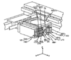
図2には、ステージ装置20が投影光学系PL、アライメント系ALG等とともに、斜視図にて概略的に示されている。また、図3には、図2の状態から干渉計システム(116,118,146,148)及びウエハステージWST1、WST2が取り除かれた状態のステージ装置20の残部が斜視図にて示されている。以下、これら図2、図3を中心として、適宜他の図面を参照しつつ、ステージ装置20の構成各部について説明する。 In FIG. 2, the stage device 20 is schematically shown in a perspective view together with the projection optical system PL, the alignment system ALG, and the like. FIG. 3 is a perspective view showing the remaining portion of the stage apparatus 20 in a state where the interferometer system (116, 118, 146, 148) and the wafer stages WST1, WST2 are removed from the state of FIG. . Hereinafter, the components of the stage apparatus 20 will be described with reference to FIGS. 2 and 3 and other drawings as appropriate.
ウエハステージWST1、WST2を駆動する駆動系は、ウエハステージWST1、WST2をそれぞれX軸方向(第1方向)に駆動するXリニアモータXM1、XM2と、ウエハステージWST1、WST2をそれぞれY軸方向(第2方向)に駆動するYリニアモータ(駆動装置)YM1、YM2とを主体に構成されている。 A drive system for driving wafer stages WST1 and WST2 includes X linear motors XM1 and XM2 for driving wafer stages WST1 and WST2 in the X-axis direction (first direction), respectively, and wafer stages WST1 and WST2 in the Y-axis direction (first direction). Y linear motors (driving devices) YM1 and YM2 driven in two directions) are mainly configured.
図3に示すように、YリニアモータYM1は、ステージ定盤SBのX軸方向両端部にY軸方向に沿って対で配設された固定子83A、83Aと、それぞれ固定子83A、83Aとの間の電磁気的相互作用により固定子83A、83Aに沿ってY軸方向に駆動される可動子84A、84Aとから構成されている。
各固定子83Aは、Y方向に延在する支持部材59A及びYガイド60Aを介してステージ定盤SBに支持されている(ただし、−X側の支持部材59Aは不図示)。各支持部材59Aは、固定子83Aの下面(−Z側の面)に設けられており、それぞれエアパッド等のエアベアリングを有しYガイド60AにY方向に非接触で移動自在に嵌合している。
そして、可動子84A、84A(ウエハステージWST1又はWST2)のY軸方向への移動に伴う反力は、固定子83A、83AのYガイド60A、60Aに沿う移動により吸収されるため、ステージ定盤SBに与える運動量は理論的にゼロとなり、ステージ装置20における重心の位置がY方向において実質的に固定される。As shown in FIG. 3, the Y linear motor YM1 includes
Each
The reaction force accompanying the movement of the
同様に、YリニアモータYM2は、ステージ定盤SBのX軸方向両端部にY軸方向に沿って対で配設された固定子83B、83Bと、それぞれ固定子83B、83Bとの間の電磁気的相互作用により固定子83B、83Bに沿ってY軸方向に駆動される可動子84B、84Bとから構成されている。
各固定子83Bは、Y方向に延在する支持部材59B及びYガイド60Bを介してステージ定盤SBに支持されている。各支持部材59Bは、固定子83Bの下面(−Z側の面)に設けられており、それぞれエアパッド等のエアベアリングを有しYガイド60BにY方向に非接触で移動自在に嵌合している。
そして、可動子84B、84B(ウエハステージWST2又はWST1)のY軸方向への移動に伴う反力は、固定子83B、83BのYガイド60B、60Bに沿う移動により吸収されるため、ステージ定盤SBに与える運動量は理論的にゼロとなり、ステージ装置20における重心の位置がY方向において実質的に固定される。Similarly, the Y linear motor YM2 includes electromagnetic waves between
Each
The reaction force accompanying the movement of the
また、ステージ定盤SBの−X側に位置する固定子83A、83Bの近傍には、Y軸方向に延びるガイド部68A、68Bがそれぞれ設けられており、−X側に位置する可動子84A、84Bにはガイド部68A、68Bに嵌合してY軸方向の移動をガイドするYスライダ69A、69Bがそれぞれ設けられている。ガイド部68A、68Bには、Yスライダ69A、69BのY軸方向の位置を計測する際に用いられるエンコーダスケールがそれぞれ形成されている。そして、Yスライダ69A、69Bには、エンコーダスケールを計測するエンコーダー(エンコーダヘッド)64A、64Bが設けられており、計測した位置情報は主制御装置50に出力される(図6参照)。 Further, guide
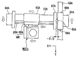
XリニアモータXM1は、X方向に沿って架設され両端を取付板67A、67Aに固定された固定子66Aと、固定子66Aとの間の電磁気的相互作用により固定子66Aに沿ってX軸方向に駆動される可動子88Aとから構成されている。また、取付板67A、67A間には、固定子66Aと平行してX軸方向に延びるYステージ(ガイド部)72Aが架設されている。このYステージ72Aは、可動子88Aと一体的に移動するX粗動ステージ63Aをガイドするものである。X粗動ステージ63Aは、断面矩形枠状の形状を有し、Yステージ72Aの4面(上下面及び両側面)を取り囲み、且つ気体静圧軸受(非接触ベアリング)である複数のエアパッド73A(図7A、図7B参照)を介して非接触で移動可能となっている。これらエアパッド73Aは、Yステージ72Aの4面のそれぞれに対向して、且つ各面においてX軸方向に間隔をあけて配置されている。 The X linear motor XM1 is constructed along the X direction along the
+X側に位置する取付板67Aは、YリニアモータYM1の可動子84Aに一体的に固定されており、−X側に位置する取付板67Aは可動子84A(Yスライダ69A)に連結部材65Aを介して連結されている。連結部材65Aは、ラジアルベアリング等で構成されており、取付板67Aを介してYステージ72Aと可動子84A(Yスライダ69A)とを、ステージ定盤SBの表面と直交する軸周り(Z軸と平行な軸周り)に回転自在に結合している。これらYステージ72Aと可動子84A(Yスライダ69A)とのθZ方向の位置関係はロータリーエンコーダ74Aで計測され、その計測結果が主制御装置50に出力される(図6参照)。 The
同様に、XリニアモータXM2は、X方向に沿って架設され両端を取付板67B、67Bに固定された固定子66Bと、固定子66Bとの間の電磁気的相互作用により固定子66Bに沿ってX軸方向に駆動される可動子88Bとから構成されている。また、取付板67B、67B間には、固定子66Bと平行してX軸方向に延びるYステージ(ガイド部)72Bが架設されている。このYステージ72Bは、可動子88Bと一体的に移動するX粗動ステージ63Bをガイドするものである。X粗動ステージ63Bは、X粗動ステージ63Aと同様に、断面矩形枠状の形状を有し、Yステージ72Bの4面(上下面及び両側面)を取り囲み、且つ気体静圧軸受(非接触ベアリング)である複数のエアパッドを介して非接触で移動可能となっている。なお、X粗動ステージ63Bにおけるエアパッドは図示を省略しているが、X粗動ステージ63Aにおけるエアパッド73Aと同様の配置で設けられている。 Similarly, the X linear motor XM2 is constructed along the
+X側に位置する取付板67Bは、YリニアモータYM2の可動子84Bに一体的に固定されており、−X側に位置する取付板67Bは可動子84B(Yスライダ69B)に連結部材65Bを介して連結されている。連結部材65Bは、ラジアルベアリング等で構成されており、取付板67Bを介してYステージ72Bと可動子84B(Yスライダ69B)とを、ステージ定盤SBの表面と直交する軸周りに回転自在に結合している。これらYステージ72Bと可動子84B(Yスライダ69B)とのθZ方向の位置関係はロータリーエンコーダ74Bで計測され、その計測結果が主制御装置50に出力される(図6参照)。 The mounting
可動子88Aの+Y側の側面には、図3に示されるように、Y軸方向に延びる固定子群を含むフォーク部70Aが片持ち状態で支持されている。同様に可動子88Bの−Y側の側面にはY軸方向に延びる固定子群を含むフォーク部70Bが片持ち状態で支持されている。これを詳述すると、一方のフォーク部70Aは、図4Aに拡大して示されるように、6つの固定子SX、SY1、SY2、SY3、SZ1、SZ2と、ガイド棒GB1とを備えている。 On the side surface on the + Y side of the
固定子SXは、内部に電機子コイルを有しており、Y軸方向を長手方向とし、ほぼXY平面に平行になるように配置されている。固定子SY1、SY2は、内部に電機子コイルを有しており、固定子SXの上下にそれぞれ所定間隔をあけてほぼ平行に配置されている。固定子SY3は、内部に電機子コイルを有しており、固定子SX、SY1、SY2から−X側に所定間隔を隔てた位置に配置されている。固定子SZ1、SZ2は、内部に電機子コイルを有しており、固定子SX、SY1、SY2の+X側及び固定子SY3の−X側にそれぞれ配置されている。ガイド棒GB1は、可動子88Aにその長手方向一端が接続された角柱状部材からなり、長手方向他端部(先端部)近傍には複数の静電容量センサからなる検出装置としてのセンサ群SSが埋め込まれている。このセンサ群SSにより、ウエハステージWST1とフォーク部70AとのX、Z軸方向及びθX、θY、θZ方向の相対位置を計測することが可能となっている(後述)。 The stator SX has an armature coil inside, and is arranged so that the Y-axis direction is the longitudinal direction and is substantially parallel to the XY plane. The stators SY1 and SY2 have armature coils inside, and are arranged substantially parallel to each other at a predetermined interval above and below the stator SX. The stator SY3 has an armature coil inside, and is arranged at a position spaced apart from the stators SX, SY1, SY2 by −X. The stators SZ1 and SZ2 have armature coils inside, and are disposed on the + X side of the stators SX, SY1 and SY2 and on the −X side of the stator SY3, respectively. The guide bar GB1 is formed of a prismatic member having one end in the longitudinal direction connected to the
図3に戻り、前記他方のフォーク部70Bも、上述したフォーク部70Aと同様に、可動子88Bの−Y側面に設けられている。このフォーク部70Bは、6つの固定子TX、TY1、TY2、TY3、TZ1、TZ2と、ガイド棒GB2とを備えている(ガイド棒GB2については図3では不図示)。これら6つの固定子TX、TY1、TY2、TY3、TZ1、TZ2及びガイド棒GB2は、上記フォーク部70Aを構成する6つの固定子SX、SY1、SY2、SY3、SZ1、SZ2及びガイド棒GB1と対称の配置でそれぞれの長手方向の一端が可動子88Bに固定されている。この場合、対応する固定子同士(具体的には、固定子TXとSX、固定子TY1とSY1、固定子TY2とSY2、固定子TY3とSY3、固定子TZ1とSZ1、固定子TZ2とSZ2)、ガイド棒GB1、GB2同士が相互に対向することができ、且つ最接近した状態では見かけ上1本の固定子などを構成しうる配置となっている。
なお、上記の対応する固定子同士、ガイド棒同士の構成は全く同様であるので、フォーク部70Bの詳細については説明を省略する。Returning to FIG. 3, the
In addition, since the structure of said corresponding stator and guide rods is completely the same, description is abbreviate | omitted about the detail of the
ウエハステージWST1は、図2に示されるように、XZ断面が略T字状のステージ本体71と、このステージ本体71に所定の位置関係で一体的に固定された可動子群とを備え、全体として概略直方体形状を呈している。可動子群は、図4Bに示されるように、6つの可動子DX、DY1、DY2、DY3、DZ1、DZ2を含んでいる。可動子DX、DY1、DY2は、それぞれ上述した固定子SX、SY1、SY2に対応するもので、これらの固定子の配置に対応して固定子SY1、SX、SY2の順で上下に積層された状態でステージ本体71の+X側且つ−Z側の空間に固定されている。また、可動子DY3、DZ2は、それぞれ上記の固定子SY3、SZ2に対応するもので、これらの固定子の配置に対応して可動子DY3、DZ2の順でステージ本体71の−X側且つ−Z側の空間に固定されている。 As shown in FIG. 2, wafer stage WST1 includes a stage
可動子DXは、矩形枠状の磁性体からなる枠状部材56と、枠状部材56の内側の上下の対向面(上面及び下面)にそれぞれ固定されたY軸方向に延びる永久磁石58A、58Bとを備えている。永久磁石58A、58Bは互いに逆磁性とされている。そして、図5に示すように、ウエハステージWST1と一方のフォーク部70Aとの係合状態では、固定子SXが永久磁石58A、58Bの間に挿入されるようになっており、固定子SXの電機子コイルを流れる電流と、永久磁石58A、58Bの間の磁界との電磁気的相互作用により発生するローレンツ力により、可動子DX(及びウエハステージWST1)が固定子SXに対してX軸方向に微小駆動されるようになっている。すなわち、固定子SXと可動子DXとによって、ウエハステージWST1をX軸方向に微小駆動するX軸微動モータVXが構成されている。 The mover DX includes a frame-shaped member 56 made of a rectangular frame-shaped magnetic body, and
可動子DY1は、可動子DXの上側に配置されており、筒状のヨーク52と、ヨーク52の内側の上下対向面にY軸方向に沿って所定間隔でそれぞれ配設された複数の界磁石54とを有している。この場合、Y軸方向に隣り合う界磁石54同士、Z軸方向で向かい合う界磁石54同士は、相互に逆磁性とされている。そして、図5に示したウエハステージWST1と一方のフォーク部70Aとの係合状態では、固定子SY1がヨーク52の内部空間に挿入されるようになっており、固定子SY1の電機子コイルを流れる電流と、ヨーク52の内部空間の交番磁界との電磁気的相互作用により発生するローレンツ力によって、可動子DY1にはY軸方向の駆動力が作用し、可動子DY1が固定子SY1に沿ってY軸方向に駆動されるようになっている。すなわち、本実施形態では、固定子SY1と可動子DY1とによって、ムービングマグネット型のY軸リニアモータLY1が構成されている。 The mover DY1 is disposed above the mover DX, and has a
可動子DY2は、可動子DXの下側に配置されており、その構成等は上記可動子DY1と同様である。従って、図5に示したウエハステージWST1と一方のフォーク部70Aとの係合状態では、可動子DY2にはY軸方向の駆動力が作用し、可動子DY2が固定子SY2に沿ってY軸方向に駆動される。すなわち、本実施形態では、固定子SY2と可動子DY2とによって、ムービングマグネット型のY軸リニアモータLY2が構成されている。 The mover DY2 is disposed below the mover DX, and the configuration thereof is the same as that of the mover DY1. Accordingly, in the engaged state between wafer stage WST1 and one
可動子DY3は、可動子DY1、DY2と設置方向及び大きさは異なるが同様に構成されている。従って、図5に示したウエハステージWST1と一方のフォーク部70Aとの係合状態では、可動子DY3にはY軸方向の駆動力が作用し、可動子DY3が固定子SY3に沿ってY軸方向に駆動される。すなわち、本実施形態では、固定子SY3と可動子DY3とによって、ムービングマグネット型のY軸リニアモータLY3が構成されている。 The mover DY3 has the same configuration as the movers DY1 and DY2, although the installation direction and size are different. Accordingly, in the engaged state between wafer stage WST1 and one
そして、本実施の形態では、Y軸リニアモータLY1、LY2それぞれの駆動力(推力)をf、Y軸リニアモータLY3の駆動力を2×fとすることで、ウエハステージWST1をフォーク部70Aに対してY軸方向に駆動(ほぼ重心駆動)することができる。また、Y軸リニアモータLY1、LY2の発生する駆動力を異ならせることで、ウエハステージWST1をX軸周りの回転方向(ピッチング方向)に微小駆動することが可能であるとともに、Y軸リニアモータLY1、LY2の発生する駆動力の合力とY軸リニアモータLY3の発生する駆動力とを異ならせることで、ウエハステージWST1をZ軸周りの回転方向(ヨーイング方向)に微小駆動することが可能である。 In this embodiment, the driving force (thrust force) of each of Y-axis linear motors LY1 and LY2 is set to f, and the driving force of Y-axis linear motor LY3 is set to 2 × f, so that wafer stage WST1 is moved to fork
なお、上記のように、本実施の形態では、上記3つのY軸リニアモータLY1〜LY3の発生する駆動力により、ウエハステージWST1をフォーク部70Aに対してY軸方向に駆動できるが、通常の露光時には、これらY軸リニアモータLY1〜LY3はウエハステージWST1のY軸方向の微小駆動に用いられ、ウエハステージWST1のY軸方向に関する粗動には上述したYリニアモータYM1が用いられる。 As described above, in the present embodiment, wafer stage WST1 can be driven in the Y-axis direction with respect to fork
可動子DZ1は、可動子DX、DY1、DY2の+X側に設けられており、XZ断面が矩形枠状の磁性体から成る枠状部材57と、該枠状部材57の内側の一対の対向面(±X側の面)にそれぞれ設けられたY軸方向に延びる一対の永久磁石62A、62Bとを備えている。永久磁石62A、62Bは互いに逆極性とされている。そして、図5に示したウエハステージWST1と一方のフォーク部70Aとの係合状態では、固定子SZ1が永久磁石62A、62Bの間に挿入されるようになっており、固定子SZ1の電機子コイルを流れる電流と、永久磁石62A、62Bの間の磁界との電磁気的相互作用により発生するローレンツ力により、可動子DZ1(及びウエハステージWST1)が固定子SZ1に対してZ軸方向に微小駆動されるようになっている。すなわち、固定子SZ1と可動子DZ1とによって、ウエハステージWST1をZ軸方向に微小駆動するZ軸微動モータVZ1が構成されている。 The mover DZ1 is provided on the + X side of the movers DX, DY1, and DY2, and has a frame-shaped
可動子DZ2は、可動子DY3の−X側に配置され、その構成は可動子DZ1と同様となっている。そして、図5に示したウエハステージWST1と一方のフォーク部70Aとの係合状態では、固定子SZ2と可動子DZ2とによって、ウエハステージWST1をZ軸方向に微小駆動するZ軸微動モータVZ2が構成されている。
本実施の形態では、Z軸微動モータVZ1、VZ2の発生する駆動力を同一とすることで、ウエハステージWST1をZ方向に微小駆動することができるとともに、各Z軸微動モータの駆動力を異ならせることにより、ウエハステージWST1をY軸周りの回転方向(ローリング方向)に微小駆動することが可能である。The mover DZ2 is disposed on the −X side of the mover DY3, and the configuration thereof is the same as that of the mover DZ1. In the engaged state between wafer stage WST1 and one
In the present embodiment, wafer stage WST1 can be finely driven in the Z direction by using the same driving force generated by Z-axis fine movement motors VZ1 and VZ2, and the driving force of each Z-axis fine movement motor is different. By doing so, it is possible to finely drive wafer stage WST1 in the rotation direction (rolling direction) around the Y axis.
上記固定子を構成する各電機子コイルに供給される電流の大きさ及び方向は、主制御装置50により制御されており、主制御装置50の制御の下、本実施の形態では、X軸微動モータVX、Y軸リニアモータLY1〜LY3、Z軸微動モータVZ1,VZ2により、ウエハステージWST1をフォーク部70Aに対して6自由度方向に微小駆動することができる。また、ステージ本体71には、Y軸方向に沿って貫通孔75が形成されており、図5に示すウエハステージWST1と一方のフォーク部70Aとの係合状態では、ガイド棒GB1が貫通孔75に挿入された状態となり、前述のセンサ群SSにより、ガイド棒GB1とステージ本体71とのY軸方向を除く5自由度方向の相対位置関係を検出することが可能である。主制御装置50は、センサ群SSの検出結果に基づいて、必要に応じて上記各モータを制御してガイド棒GB1とステージ本体71との位置関係を調整する。 The magnitude and direction of the current supplied to each armature coil constituting the stator is controlled by the
なお、本実施の形態においては、前述のようにフォーク部70Bを構成する6つの固定子TX、TY1、TY2、TY3、TZ1、TZ2及びガイド棒GB2は、フォーク部70Aを構成する6つの固定子SX、SY1、SY2、SY3、SZ1、SZ2及びガイド棒GB1とそれぞれ同様に構成され、且つ対称の配置となっていることから、ウエハステージWST1は、一方のフォーク部70Aのみならず、他方のフォーク部70Bに対しても、反対方向から上記と同様に係合可能である。
この場合、ウエハステージWST1の可動子DXと固定子TX、可動子DY1と固定子TY1、可動子DY2と固定子TY2、可動子DY3と固定子TY3、可動子DZ1と固定子TZ1、可動子DZ2と固定子TZ2がそれぞれ係合する。
また、ウエハステージWST2は、ウエハステージWST1と同様の構成を有しているため詳述はしないが、フォーク70A、70Bのいずれに対しても着脱自在となっている。In the present embodiment, as described above, the six stators TX, TY1, TY2, TY3, TZ1, TZ2 and the guide rod GB2 constituting the
In this case, mover DX and stator TX, mover DY1 and stator TY1, mover DY2 and stator TY2, mover DY3 and stator TY3, mover DZ1 and stator TZ1, and mover DZ2 of wafer stage WST1. And the stator TZ2 engage with each other.
Wafer stage WST2 has the same configuration as wafer stage WST1, and will not be described in detail. However, wafer stage WST2 is detachable from both
一方のウエハステージWST1の上面(+Z側の面)には、図2に示されるように、Y軸方向の一側(−Y側)の端部に、X軸方向に延びるY移動鏡MY1が固定され、X軸方向の一側(+X側)の端部に、Y軸方向に延びるX移動鏡MX1が固定されている。移動鏡MY1、MX1の各反射面には、Y干渉計116、X干渉計146からの干渉計ビーム(測長ビーム)がそれぞれ投射される。そして、Y干渉計116、X干渉計146で各反射面からの反射光を受光することにより、各反射面の基準位置(一般には投影光学系側面や、アライメント系の側面に固定ミラーを配置し、そこを基準面とする)からの変位が計測され、これによりウエハステージWST1の2次元位置が計測される。 On the upper surface (the surface on the + Z side) of one wafer stage WST1, as shown in FIG. 2, a Y movable mirror MY1 extending in the X-axis direction is provided at one end (−Y side) in the Y-axis direction. An X movable mirror MX1 extending in the Y axis direction is fixed to one end (+ X side) of the X axis direction. Interferometer beams (measurement beams) from the
同様に、ウエハステージWST2の上面には、Y軸方向の一側(−Y側)の端部に、X軸方向に延びるY移動鏡MY2が固定され、X軸方向の一側(+X側)の端部に、Y軸方向に延びるX移動鏡MX2が固定されている。移動鏡MY2、MX2の各反射面には、Y干渉計118、X干渉計148からの干渉計ビーム(測長ビーム)がそれぞれ投射される。そして、前述と同様に、Y干渉計118、X干渉計148で各反射面からの反射光を受光することによりウエハステージWST2の2次元位置が計測される。 Similarly, on the upper surface of wafer stage WST2, Y movable mirror MY2 extending in the X-axis direction is fixed to one end (−Y side) in the Y-axis direction, and one side (+ X side) in the X-axis direction. The X movable mirror MX2 extending in the Y-axis direction is fixed to the end portion. Interferometer beams (measurement beams) from the
図1に戻り、前記照明系12は、光源、及び照明光学系を含み、その内部に配置された視野絞り(マスキングブレード又はレチクルブラインド)で規定される矩形又は円弧状の照明領域IARにエネルギビームとしての照明光ILを照射し、回路パターンが形成されたレチクルRを均一な照度で照明する。ここで、照明系ILとしては、KrFエキシマレーザ光(波長248nm)、ArFエキシマレーザ光(波長193nm)などの遠視外光、あるいはF2レーザ光(波長157nm)などの真空紫外光などが用いられる。Returning to FIG. 1, the illumination system 12 includes a light source and an illumination optical system, and an energy beam is applied to a rectangular or arcuate illumination area IAR defined by a field stop (masking blade or reticle blind) disposed therein. The illumination light IL is irradiated to illuminate the reticle R on which the circuit pattern is formed with uniform illuminance. Here, as the illumination system IL, far-infrared light such as KrF excimer laser light (wavelength 248 nm), ArF excimer laser light (wavelength 193 nm), or vacuum ultraviolet light such as F 2 laser light (wavelength 157 nm) is used. .
前記レチクルステージRST上には、レチクルRが、例えば真空吸着により固定されている。レチクルステージRSTは、レチクル駆動部22によって照明系12の光軸(投影光学系PLの光軸AXに一致)に垂直なXY平面内でX軸方向、Y軸方向及びθZ方向(Z軸周りの回転方向)に微小駆動可能であるとともに、不図示のレチクルステージ定盤の上面に沿って所定の走査方向(Y軸方向)に指定された走査速度で駆動可能となっている。なお、レチクルステージ駆動部22は、リニアモータ、ボイスコイルモータ等を駆動源とする機構であるが、図1では図示の便宜上から単なるブロックとして示されている。なお、レチクルステージRSTとしては、Y軸方向に一次元駆動する粗動ステージと、該粗動ステージに対してレチクルRを少なくとも3自由度方向(X軸方向、Y軸方向、及びθZ方向)に微小駆動可能な微動ステージとを有する粗微動構造のステージを採用してもよい。 On reticle stage RST, reticle R is fixed, for example, by vacuum suction. Reticle stage RST is driven by
レチクルステージRSTのXY平面内の位置(θZ回転を含む)は、レチクルレーザ干渉計(以下、レチクル干渉計と称する)16によって、レチクルステージRST端部に形成された(又は設けられた)反射面を介して、例えば0.5〜1nm程度の分解能で常時検出される。レチクル干渉計16からのレチクルステージRSTの位置情報(θZ回転量(ヨーイング量)などの回転情報を含む)は、主制御装置50に出力される。主制御装置50では、レチクルステージRSTの位置情報に基づいてレチクルステージ駆動部22を介してレチクルステージRSTを駆動制御する。 The position of reticle stage RST in the XY plane (including θZ rotation) is a reflecting surface formed (or provided) at the end of reticle stage RST by reticle laser interferometer (hereinafter referred to as reticle interferometer) 16. For example, it is always detected with a resolution of about 0.5 to 1 nm. Position information of reticle stage RST (including rotation information such as θZ rotation amount (yaw amount)) from
前記投影光学系PLとしては、物体面側(レチクル側)と像面側(ウエハ側)の両方がテレセントリックでその投影倍率が1/4(又は1/5)の縮小系が用いられている。このため、レチクルRに照明系12から照明光(紫外パルス光)ILが照射されると、レチクルR上に形成された回路パターン領域のうちの紫外パルス光によって照明された部分からの結像光束が投影光学系PLに入射し、その照明光ILの照明領域IAR内の回路パターンの像(部分倒立像)が紫外パルス光の各パルス照射の度に投影光学系PLの像面側の視野中央にX軸方向に細長いスリット状(又は矩形状(多角形))に制限されて結像される。これにより、投影された回路パターンの部分倒立像は、投影光学系PLの結像面に配置されたウエハW1又はW2上の複数のショット領域の中の一つのレジスト層に縮小転写される。 As the projection optical system PL, a reduction system in which both the object plane side (reticle side) and the image plane side (wafer side) are telecentric and the projection magnification is 1/4 (or 1/5) is used. For this reason, when the illumination light (ultraviolet pulsed light) IL is irradiated from the illumination system 12 onto the reticle R, the image forming light beam from the portion illuminated by the ultraviolet pulsed light in the circuit pattern region formed on the reticle R. Is incident on the projection optical system PL, and the image of the circuit pattern (partial inverted image) in the illumination area IAR of the illumination light IL is the center of the visual field on the image plane side of the projection optical system PL for each pulse irradiation of the ultraviolet pulse light The image is limited to a slit shape (or rectangular shape (polygon)) elongated in the X-axis direction. As a result, the partially inverted image of the projected circuit pattern is reduced and transferred to one resist layer in a plurality of shot regions on the wafer W1 or W2 arranged on the imaging plane of the projection optical system PL.
投影光学系PLとしては、照明光ILとしてKrFエキシマレーザ光又はArFエキシマレーザ光などを用いる場合には、屈折光学素子(レンズ素子)のみから成る屈折系が主として用いられるが、照明光ILとしてF2レーザ光を用いる場合には、例えば特開平3−282527号公報に開示されるような、屈折光学素子と反射光学素子(凹面鏡やビームスプリッタ等)とを組み合わせた、いわゆるカタディオプトリック系(反射屈折系)、あるいは反射光学素子のみから成る反射系が主として用いられる。ただし、F2レーザ光を用いる場合には、屈折系を用いることは可能である。As the projection optical system PL, when KrF excimer laser light, ArF excimer laser light, or the like is used as the illumination light IL, a refraction system composed only of refractive optical elements (lens elements) is mainly used. When two laser beams are used, for example, a so-called catadioptric system (reflective) in which a refractive optical element and a reflective optical element (such as a concave mirror or a beam splitter) are combined as disclosed in JP-A-3-282527. A refraction system) or a reflection system composed only of a reflective optical element is mainly used. However, when using F 2 laser light, it is possible to use a refraction system.
図1に戻り、投影光学系PLの+Y側には、オフアクシス方式のアライメント系ALGが、投影光学系PLの光軸(レチクルパターン像の投影中心とほぼ一致)より所定距離だけ離れた位置に設置されている。このアライメント系ALGは、LSA(Laser Step Alignment)系、FIA(Filed Image Alignment)系、LIA(Laser Interferometric Alignment)系の3種類のアライメントセンサを有しており、基準マーク板上の基準マーク及びウエハ上のアライメントマークのX、Y2次元方向の位置計測を行なうことが可能である。ここで、LSA系は、レーザ光をマークに照射して、回折・散乱された光を利用してマーク位置を計測する最も汎用性のあるセンサであり、従来から幅広いプロセスウエハに使用される。FIA系は、ハロゲンランプ等のブロードバンド(広帯域)光でマークを照明し、このマーク画像を画像処理することによってマーク位置を計測するセンサであり、アルミ層やウエハ表面の非対称マークに有効に使用される。また、LIA系は、回折格子状のマークに周波数をわずかに変えたレーザ光を2方向から照射し、発生した2つの回折光を干渉させて、その位相からマークの位置情報を検出するセンサであり、低段差や表面荒れウエハに有効に使用される。本実施形態では、これら3種類のアライメントセンサを、適宜目的に応じて使い分け、ウエハ上の3点の一次元マークの位置を検出してウエハの概略位置計測を行なういわゆるサーチアライメントや、ウエハ上の各ショット領域の正確な位置計測を行なうファインアライメント等を行なうようになっている。 Returning to FIG. 1, on the + Y side of the projection optical system PL, the off-axis alignment system ALG is located at a position away from the optical axis of the projection optical system PL (almost coincident with the projection center of the reticle pattern image) by a predetermined distance. is set up. This alignment system ALG has three types of alignment sensors, LSA (Laser Step Alignment), FIA (Filled Image Alignment), and LIA (Laser Interferometric Alignment) systems. It is possible to measure the position of the upper alignment mark in the X and Y two-dimensional directions. Here, the LSA system is the most versatile sensor that irradiates a mark with a laser beam and measures the mark position using diffracted / scattered light, and has been conventionally used for a wide variety of process wafers. The FIA system is a sensor that measures the mark position by illuminating the mark with broadband light such as a halogen lamp and processing the image of the mark, and is effectively used for asymmetric marks on the aluminum layer and wafer surface. The In addition, the LIA system is a sensor that irradiates a diffraction grating mark with laser light having a slightly different frequency from two directions, causes the generated two diffracted lights to interfere, and detects the position information of the mark from the phase. Yes, it can be used effectively for low step and rough wafers. In the present embodiment, these three types of alignment sensors are properly used according to the purpose, so-called search alignment in which the approximate position of the wafer is measured by detecting the position of three-dimensional marks on the wafer, or on the wafer. Fine alignment or the like for performing accurate position measurement of each shot area is performed.
また、図1では図示が省略されているが、投影光学系PL、アライメント系ALGのそれぞれには、合焦位置を調べるためのオートフォーカス/オートレベリング計測機構(以下、「AF/AL系」という)がそれぞれ設けられている。このように、投影光学系PL及びアライメント系ALGのそれぞれに、オートフォーカス/オートレベリング計測機構を設けた露光装置の構成は、例えば特開平10−214783号公報に詳細に開示されており、公知であるから、ここではこれ以上の説明を省略する。従って、本実施形態では、上記特開平10−214783号公報に記載の露光装置と同様に、アライメント系ALGによるアライメントセンサの計測時に、露光時と同様のAF/AL系の計測、制御によるオートフォーカス/オートレベリングを実行しつつアライメントマークの位置計測を行なうことにより、高精度なアライメント計測が可能になる。換言すれば、露光時とアライメント時との間で、ステージの姿勢によるオフセット(誤差)が発生しなくなる。 Although not shown in FIG. 1, each of the projection optical system PL and the alignment system ALG has an autofocus / autoleveling measurement mechanism (hereinafter referred to as “AF / AL system”) for checking the in-focus position. ) Are provided. As described above, the configuration of the exposure apparatus provided with the autofocus / autoleveling measurement mechanism in each of the projection optical system PL and the alignment system ALG is disclosed in detail in, for example, Japanese Patent Application Laid-Open No. 10-214783 and is publicly known. Therefore, further explanation is omitted here. Accordingly, in the present embodiment, as in the exposure apparatus described in the above-mentioned Japanese Patent Application Laid-Open No. 10-214783, autofocus by AF / AL measurement and control similar to exposure is performed during alignment sensor measurement by the alignment system ALG. / By measuring the position of the alignment mark while performing auto-leveling, highly accurate alignment measurement is possible. In other words, an offset (error) due to the posture of the stage does not occur between exposure and alignment.
図6には、本実施形態に係る露光装置10の制御系の主要な構成が示されている。この制御系は、装置全体を統括的に制御する主制御装置50及び、この主制御装置50に計測結果を出力する各種計測機器及び、これらの計測結果に基づいて駆動される各種駆動装置から構成される。
なお、以下の説明では、主制御装置50の制御により各種駆動装置が駆動される点については記載を省略する。FIG. 6 shows the main configuration of the control system of the
In the following description, the description of the point that the various driving devices are driven by the control of the
続いて、本実施形態に係る露光装置10におけるステージ装置20の動作について説明する。なお、ウエハステージWST1、WST2の動作が同様であるため、ここでは、一方のウエハステージWST1の例を用いて説明する。
露光動作やアライメント動作により、ウエハステージWST1をY軸方向に移動させる際、主制御装置50はYリニアモータYM1を長ストロークで駆動するとともに、Y軸リニアモータLY1〜LY3を微小駆動する。
また、ステップ移動等によりウエハステージWST1をX軸方向に移動させる際、主制御装置50は、XリニアモータXM1を長ストロークで駆動するとともに、X軸微動モータVXを微小駆動する。Subsequently, the operation of the stage apparatus 20 in the
When moving wafer stage WST1 in the Y-axis direction by exposure operation or alignment operation,
Further, when moving wafer stage WST1 in the X-axis direction by step movement or the like,
このウエハステージWST1のX軸方向への移動時、特に加速又は減速する際にウエハステージWST1の慣性力により、X粗動ステージ63Aには推力に応じたモーメント負荷が加わる。例えば、図7Aに示すように、加速時にXリニアモータXM1の可動子88Aを−X側へ駆動した際には、ウエハステージWST1に関して+X側への慣性力が作用するため、結果としてX粗動ステージ63AにはZ軸と平行な軸に関して反時計回り方向のモーメント負荷が加わる。 During the movement of wafer stage WST1 in the X-axis direction, particularly when accelerating or decelerating, moment load corresponding to the thrust is applied to X
ここで、Yステージ72Aは、連結部材65AによりZ軸と平行な軸周りに回転自在にYスライダ69Aに結合しているため、X粗動ステージ63Aに加わったモーメント負荷はエアパッド73Aを介してYステージ72Aに伝わり、Yステージ72Aが連結部材65Aを回転中心として回転する。すなわち、ウエハステージWST1のX軸方向への移動に伴って生じるモーメント負荷に対して、Yステージ72Aがカウンタマスとして機能するため、X粗動ステージ63A(エアパッド73A)に加わるモーメント負荷が緩和される。
例えばX粗動ステージ63Aのイナーシャ(慣性モーメント)をIx、Yステージ72AのイナーシャをIyとすると、Yステージ72Aがカウンタマスとして機能して回転することで、エアパッド73Aに加わるモーメント負荷は、Iy/(Ix+Iy)倍に緩和される。Here, since the
For example, if the inertia (moment of inertia) of the X
同様に、ウエハステージWST1の減速時には、図7Bに示すように、ウエハステージWST1に関して−X側への慣性力が作用するため、結果としてX粗動ステージ63AにはZ軸と平行な軸に関して時計回り方向のモーメント負荷が加わるが、Yステージ72Aがカウンタマスとして、連結部材65Aを回転中心として回転するため、X粗動ステージ63A(エアパッド73A)に加わるモーメント負荷が緩和される。
なお、ウエハステージWST1の加速、減速によりYステージ72A及びX粗動ステージ63Aが回転した場合でも、ウエハステージWST1は、主制御装置50の制御の下、干渉計116、146の計測結果に基づいてX軸微動モータVX、Y軸リニアモータLY1〜LY3、Z軸微動モータVZ1,VZ2の駆動により、その位置、姿勢を制御される。Similarly, when the wafer stage WST1 is decelerated, as shown in FIG. 7B, an inertial force to the −X side acts on the wafer stage WST1, and as a result, the X
Even when
また、Yステージ72Aがカウンタマスとして機能して、モーメント負荷が緩和されてもエアパッド73Aにおける許容値に達しない場合等には、主制御装置50はYリニアモータYM1の可動子84A、84Aを制御して、エアパッド73Aに加わる負荷を逃がす方向に駆動する。具体的には、図8中、時間とX軸方向への推力との関係を示す上側のグラフのように、エアパッド73Aに加わる負荷が大きくて危険な範囲Fkに到る推力でXリニアモータXM1を駆動する際には、主制御装置50は推力が範囲FkにあるときにYステージ72Aの回転を促進するように、エンコーダー64A及びロータリーエンコーダ74Aの計測結果をモニタしつつ、YリニアモータYM1の中、加速時には+X側の可動子84Aを−Y側に駆動(トルクを入力)するとともに、−X側の可動子84Aを+Y側に駆動する(つまり、一対のYリニアモータYM1、YM1を差動する)。 Further, when the
これにより、エアパッド73Aに加わる負荷は一層緩和され、さらに可動子84A、84Aの推力を調整することで、負荷をゼロとすることも可能である。
なお、減速時においては、加速時とは逆に推力が範囲Fkにあるときに、YリニアモータYM1の中、+X側の可動子84Aを+Y側に駆動するとともに、−X側の可動子84Aを−Y側に駆動する。Thereby, the load applied to the
During deceleration, contrary to acceleration, when the thrust is in the range Fk, in the Y linear motor YM1, the +
ここで、エアパッド73Aに加わる負荷を緩和するために、可動子84A、84Aを駆動する際の推力(入力トルク)について説明する。
まず、ウエハステージWST1の移動に伴う粗動ステージ63A及びYステージ72Aの回転運動は、図9に示すバネマス系にモデル化できる。
すなわち、このバネマス系においては、質量mcのX粗動ステージ63Aと質量myのYステージ72Aとが定数kのバネ系としてのエアパッド73Aを介して連結されている。そして、ウエハステージWST1の駆動時に粗動ステージ63Aに力Fcが加わった際の変位をXc、YリニアモータYM1(可動子84A)により推力FyでYステージ72Aを駆動した際の変位をXyとすると、エアパッド73Aに加わる負荷Fpは下式で表される。
Fp=k×(Xc−Xy)Here, thrust (input torque) when driving the
First, the rotational motion of the
That is, in this spring mass system, an X
Fp = k × (Xc−Xy)
ここで、力Fc(s)から負荷Fp(s)への力の伝達関数をGc(s)、推力Fy(s)から負荷Fp(s)への力の伝達関数をGy(s)とすると下式が成り立つ。
Fp(s)=Gc(s)×Fc(s)+Gy(s)×Fy(s) …(A)
そして、Gc(s)、Fc(s)、Gy(s)については既知であるため、エアパッド73Aに過負荷がかからない値Fp(s)となるように、式(A)に基づいて可動子84Aの推力Fy(s)を設定すればよい。Here, if the force transfer function from the force Fc (s) to the load Fp (s) is Gc (s) and the force transfer function from the thrust Fy (s) to the load Fp (s) is Gy (s). The following equation holds.
Fp (s) = Gc (s) × Fc (s) + Gy (s) × Fy (s) (A)
Since Gc (s), Fc (s), and Gy (s) are already known, the
なお、粗動ステージ63Aの質量をmc、Yステージ72Aの質量をmyとすると、伝達関数Gc(s)は下記の式(B)で示され、伝達関数Gy(s)は下記の式(C)で示される。そして、低周波域においては、式(A)〜(C)から式(D)が導かれる。 When the mass of the

例えば、式(D)から明らかなように、Fy=(−my/mc)×Fcとなる推力でYリニアモータYM1を駆動することにより、エアパッド73Aに加わる負荷Fpをゼロとすることが可能となる。
また、可動子84A、84Aを駆動せずにYステージ72Aをカウンタマスとしてのみ機能させる場合、Fy=0となるため、エアパッド73Aに加わる負荷Fpは式(E)で表される。For example, as is clear from the equation (D), the load Fp applied to the
Further, when the
次に、露光装置10における露光動作とアライメント動作との並行処理を含む一連の動作について図10A乃至図12Bを参照して説明する。
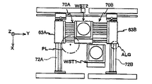
図10Aには、ウエハステージWST1上のウエハW1に対して露光動作が行われるのと並行して、ウエハステージWST2上のウエハW2に対してウエハアライメント動作が行われている状態が示されている。Next, a series of operations including parallel processing of the exposure operation and the alignment operation in the
FIG. 10A shows a state in which the wafer alignment operation is being performed on wafer W2 on wafer stage WST2 in parallel with the exposure operation being performed on wafer W1 on wafer stage WST1. .
この図10Aに先立って、所定のローディングポジションにウエハステージWST2があるときに、不図示のウエハローダによって、ウエハステージWST2上に載置されていた露光済みのウエハのアンロード及び新たなウエハW2のウエハステージWST2上へのロード(即ちウエハ交換)が行われる。 Prior to this FIG. 10A, when wafer stage WST2 is in a predetermined loading position, the wafer loader (not shown) unloads the exposed wafer placed on wafer stage WST2 and a new wafer W2 wafer. Loading on stage WST2 (ie, wafer exchange) is performed.
そして、主制御装置50は、干渉計118、148(図10A〜10Cでは不図示、図2参照)の計測値に基づいてウエハステージWST2のXY面内の位置を管理しつつ、アライメント系ALGを用いて、ウエハW2上の特定の複数のショット領域(サンプルショット領域)に付設されたアライメントマーク(サンプルマーク)の位置情報を検出する。
次いで、主制御装置50は、その検出結果とその特定ショット領域の設計上の位置座標とに基づいて、例えば特開昭61−44429号公報等に開示される最小二乗法を用いた統計演算によりウエハW2上の全てのショット領域の配列座標を求めるEGA(エンハンスト・グローバル・アライメント)方式のウエハアライメント計測を実施する。また、この場合、主制御装置50は、サンプルマークの位置情検出に前後して、ウエハステージWST2上の基準マーク板(不図示)の第1基準マークの位置情報を検出する。そして、主制御装置50は、先に求めたウエハW2上の全てのショット領域の配列座標を、第1基準マークの位置を原点とする位置座標に変換する。Then,
Next,
なお、上記のウエハ交換、ウエハアライメントの際、主制御装置50は、干渉計118、148による検出結果に基づいて、ウエハステージWST2をX軸リニアモータXM2及び一対のY軸リニアモータYM2、YM2を介して長ストロークで駆動するとともに、ウエハステージWST2を前述の6自由度駆動機構を介してフォーク部70Bに対して相対的にX、Y、Z、θX、θY、θZ方向に関して微小駆動する。なお、Z、θX、θY方向の駆動に際しては、前述のAF/AL系の計測結果が考慮される。 During the wafer exchange and wafer alignment described above,
このように、ウエハステージWST2側でウエハ交換、ウエハアライメントが実行される。このウエハ交換、ウエハアライメントと並行して、ウエハステージWST1側では、既に行われたウエハアライメント結果に基づいてウエハステージWST1上に載置されたウエハW1上の各ショット領域の露光のための加速開始位置にウエハステージWST1を移動させるショット間ステッピング動作と、レチクルR(レチクルステージRST)とウエハW1(ウエハステージWST1)とをY軸方向に相対走査して、レチクルRに形成されたパターンをウエハW1上のショット領域に投影光学系PLを介して転写する走査露光動作とを繰り返す、ステップ・アンド・スキャン方式の露光動作が行われる。 In this way, wafer exchange and wafer alignment are performed on the wafer stage WST2 side. In parallel with this wafer exchange and wafer alignment, on the wafer stage WST1 side, acceleration start for exposure of each shot area on wafer W1 placed on wafer stage WST1 based on the already performed wafer alignment result is started. A stepping operation between shots for moving wafer stage WST1 to the position, reticle R (reticle stage RST) and wafer W1 (wafer stage WST1) are relatively scanned in the Y-axis direction, and the pattern formed on reticle R is wafer W1. A step-and-scan type exposure operation is performed in which the scanning exposure operation of transferring to the upper shot area via the projection optical system PL is repeated.
上記のステップ・アンド・スキャン方式の露光動作の開始に先立って、主制御装置50は、干渉計116、146(図10A〜10Cでは不図示、図2参照)の計測結果に基づいてウエハステージWST1の位置を管理しつつ、ウエハステージWST1上の不図示の基準マーク板上の第2の基準マークとレチクルR上のレチクルアライメントマークとをレチクルアライメント系を用いて計測する。そして、主制御装置50では、その計測結果と上記ウエハアライメントの結果とに基づいてウエハW1上の各ショット領域の露光のための加速開始位置にウエハステージWST1を移動させる。 Prior to the start of the above-described step-and-scan exposure operation,
上記のステップ・アンド・スキャン方式の露光動作中、主制御装置50は、ウエハステージWST1をX軸リニアモータXM1及び一対のY軸リニアモータYM1、YM1を介して長ストロークで駆動するとともに、ウエハステージWST1を前述の6自由度駆動機構を介してフォーク部70Aに対して相対的にX、Y、Z、θX、θY、θZ方向に関して微小駆動する。なお、Z、θX、θY方向の駆動に際しては、前述のAF/AL系の計測結果が考慮される。また、この露光動作そのものの手順等は、通常のスキャニング・ステッパと同様であるので、これ以上の詳細な説明は省略する。 During the above-described step-and-scan exposure operation,
上述したウエハステージWST2上のウエハW2に対するウエハアライメント動作と、ウエハステージWST1上のウエハW1に対する露光動作とでは、通常はウエハアライメント動作が先に終了する。そこで、主制御装置50は、ウエハアライメントの終了後、X軸リニアモータXM2及び一対のY軸リニアモータYM2、YM2を介してウエハステージWST2を+Y方向及び−X方向に駆動する。そして、ウエハステージWST2を所定の待機位置(図10Bに示されるウエハステージWST2の位置)に移動させ、その位置で待機させる。 In the wafer alignment operation for wafer W2 on wafer stage WST2 and the exposure operation for wafer W1 on wafer stage WST1, the wafer alignment operation is usually finished first. Therefore,
その後、ウエハステージWST1上のウエハW1に対する露光動作が終了すると、主制御装置50は、X軸リニアモータXM1及び一対のY軸リニアモータYM1を介してウエハステージWST1を+X方向及び+Y方向に移動させる。図10Bには、この移動完了後の状態が示されている。 Thereafter, when the exposure operation for wafer W1 on wafer stage WST1 is completed,
次いで、主制御装置50は、ウエハステージWST1側の上記6自由度機構を構成するフォーク部70Aの各固定子への電流供給を停止する。これにより、Z軸微動モータVZ1、VZ2の固定子SZ1、SZ2への電流供給も停止され、ウエハステージWST1をZ軸方向に非接触支持する支持力(駆動力)も解除され、ウエハステージWST1は定盤SB上に載置される。この状態から、主制御装置50は一対のY軸リニアモータYM1を介してX軸リニアモータXM1及びフォーク部70Aを−Y方向に移動させる。これにより、ウエハステージWST1がフォーク部70Aから離脱する。図10Cには、X軸リニアモータXM1及びフォーク部70Aの−Y方向への移動が終了し、ウエハステージWST1がフォーク部70Aから離脱した状態が示されている。 Next,
次いで、主制御装置50は、X軸リニアモータXM1、Y軸リニアモータYM1を介してX粗動ステージ63Aと一体でフォーク部70Aを−X方向及び+Y方向に移動させるとともに、一対のY軸リニアモータYM2を介してウエハステージWST2と一体でフォーク部70Bが設けられたX粗動ステージ63Bを−Y方向に移動させる。そして、図11Aに示されるように、フォーク部70Aの+Y側端部とフォーク部70Bの−Y側端部とを最接近(又は接触)させる。これにより、フォーク部70A、70Bの固定子同士、ガイド棒同士が数μm〜数mm程度のクリアランスを介して接近し、見かけ上一体に連結される。 Next,
そして、フォーク部70A、70Bが連結された状態で、主制御装置50は、フォーク部70Bを構成する固定子TY1〜TY3が有する各電機子コイル、及びフォーク部70Aを構成する固定子SY1〜SY3が有する各電機子コイルに順次電流を供給し、ウエハステージWST2をフォーク部70B(及び70A)に対して−Y方向に移動させる。
これにより、ウエハステージWST2は、フォーク部70Bからフォーク部70Aに受け渡される。図11Bには、このウエハステージWST2の受け渡しの途中の状態が示されている。Then, in a state where the
Thereby, wafer stage WST2 is transferred from
この受け渡し(移動)の際には、ウエハステージWST2とフォーク部70A,70Bとの位置関係がガイド棒GB1、GB2に設けられたセンサ群SSにより計測されるので、フォーク部70A、70Bの位置が所定の位置から多少ずれた場合でも、そのセンサ群SSの検出結果に基づいて、ウエハステージWST2を6自由度機構により微小駆動(位置調整)することで、フォーク部70Aからフォーク部70BへのウエハステージWST2の受け渡しを非接触で、且つ高速で行うことが可能である。 In this delivery (movement), the positional relationship between wafer stage WST2 and
そして、ウエハステージWST2がフォーク部70Aに完全に渡された段階で、主制御装置50は干渉計116、146の計測値に基づいてウエハステージWST2の位置を管理しつつ、ウエハステージWST2上の不図示の基準マーク板上の一対の基準マークとレチクルR上の一対のレチクルアライメントマークを前述のレチクルアライメント系を用いて計測する。そして、主制御装置50では、その計測結果と先に行われたウエハアライメントの結果とに基づいてウエハW2上の第1ショット領域の露光のための加速開始位置にウエハステージWST1を移動させる。その後は、ウエハW2に対するステップ・アンド・スキャン方式の露光動作が上記ウエハW1に対する露光と同様にして行われる。 Then, at the stage where wafer stage WST2 is completely transferred to fork
この一方、主制御装置50は、上記のウエハステージWST2のフォーク部70Bからフォーク部70Aへの受け渡しの終了により、ウエハステージWST1、WST2のいずれとも係合せず、フリーの状態となっているフォーク部70BをX粗動ステージ63Bと一体で、Y軸リニアモータYM2、X軸リニアモータXM2を介して、定盤SB上に載置されているウエハステージWST1に接近するように移動する(図11C参照)。 On the other hand,
そして、ウエハステージWST1とフォーク部70BとのX軸方向の位置が一致した図11Cの状態から、主制御装置50はウエハステージWST1とフォーク部70Bとが係合するように、Y軸リニアモータYM2を介して、フォーク部70BをX粗動ステージ63Bと一体で−Y方向に駆動し、図12Aの状態とする。この場合に、ウエハステージWST1に形成された貫通孔75(図4B参照)に前記ガイド棒GB2が挿入された状態でガイド棒GB2に設けられたセンサ群を介して、ガイド棒GB2とステージ本体71との位置関係を検出することができるため、主制御装置50は、この検出結果に基づいてウエハステージWST1とフォーク部70Bとの関係を調整しつつ、フォーク部70Bを駆動することが可能である。このようにして、ウエハステージWST1がフォーク部70Bに係合した段階で、主制御装置50は6自由度機構を構成するZ軸モータに+Z方向の駆動力を発生させ、フォーク部70BがウエハステージWST1を非接触で支持するように、その駆動力を制御する。 Then, from the state of FIG. 11C in which the positions of wafer stage WST1 and
その後、主制御装置50はウエハステージWST1上に載置された露光済みのウエハW1と次の露光対象であるウエハW3(図12B参照)との交換を行うとともに、ウエハW3のウエハアライメント動作が上記と同様に実施される。
このようにして、本実施の形態の露光装置10では、ウエハステージWST1、WST2の交換を行いつつ、一方のウエハステージ上のウエハに対する露光動作と、他のウエハステージ上でのウエハ交換及びウエハアライメント動作とが、同時並行処理にて行われる。Thereafter,
In this way, in
これら露光動作、ウエハ交換及びウエハアライメント動作においてウエハステージWST1、WST2がX方向に移動した際には、その移動方向及び加速度に応じてYステージ72A、72Bが回転することで、X粗動ステージ63A(エアパッド73A)に加わるモーメント負荷が緩和される。 When the wafer stages WST1 and WST2 move in the X direction in these exposure operations, wafer exchanges and wafer alignment operations, the Y stages 72A and 72B rotate in accordance with the movement direction and acceleration, so that the X
以上のように、本実施の形態では、ウエハステージWST1、WST2のX軸方向の移動に際して、Yステージ72A、72Bにモーメント負荷が加わる場合でも、Yステージ72A、72Bが連結部材65A、65Bを回転中心として回転してカウンタマスとして機能するため、X粗動ステージ63A、63Bすなわちエアパッド73A、73Bに加わる負荷を軽減することが可能になる。そのため、本実施の形態では、エアパッド73A、73Bにギャップつぶれが生じることを防止できるため、X粗動ステージ63A、63BとYステージ72A、72Bとが接触して損傷してしまうことを回避でき、装置の安全性を向上させることができる。 As described above, in the present embodiment, when moment loads are applied to
さらに、本実施の形態では、エアパッド73A、73Bに加わる負荷が大きい場合には、YリニアモータYM1、YM2を駆動してYステージ72A、72Bの回転を促進するため、エアパッド73A、73Bに加わる負荷を効果的に緩和することが可能となり、装置の安全性を一層高めることができる。また、本実施の形態では、上記Yステージ72A、72Bを回転可能とするためには、連結部材65A、65Bを用いて可動子84A、84B(Yスライダ69A、69B)と連結するだけであり、また、Yステージ72A、72Bをアクティブに回転させる際にはYリニアモータYM1、YM2を差動させるだけなので、特殊な装置を別途設けることがなく装置の小型化及び低価格化にも寄与することが可能である。 Furthermore, in this embodiment, when the load applied to the
(第2実施形態)
続いて、本発明のステージ駆動方法に係る第2実施形態について説明する。
上記第1実施形態では、Yリニアモータの差動によりYステージ72A、72Bを回転させることでエアパッド73A、73Bに加わる負荷を軽減させていたが、この方法では、ウエハステージが連続して同一方向に移動した場合等には回転方向も同一となるため、回転量が積算されてYステージ72A、72Bが大きく傾いてしまう事態が生じる可能性がある。
そのため、本実施の形態においては、露光中にYステージ72A、72Bの姿勢を補正するステップを設ける場合について図13及び図14A、14Bを参照して説明する。(Second Embodiment)
Subsequently, a second embodiment according to the stage driving method of the present invention will be described.
In the first embodiment, the load applied to the
Therefore, in the present embodiment, a case where a step for correcting the postures of the Y stages 72A and 72B is provided during exposure will be described with reference to FIGS. 13 and 14A and 14B.
図13中、時間とX軸方向への推力との関係を示す上側のグラフにおいては、ウエハステージWST1、WST2がX軸方向に移動するステップ工程と、ウエハステージWST1、WST2(のいずれか)がレチクルRとともにY軸方向に同期移動する露光工程とが交互に繰り返して行われる。このステップ工程においては、図8を用いて説明したように、エアパッドに加わる負荷が大きくて危険な範囲Fkに到る推力でXリニアモータを駆動する際には、主制御装置50はYステージの回転を促進するように、Yリニアモータを差動状態で駆動する。 In the upper graph showing the relationship between time and thrust in the X-axis direction in FIG. 13, a step process in which wafer stages WST1 and WST2 move in the X-axis direction and wafer stage WST1 and WST2 (any one) are shown. The exposure process of synchronously moving in the Y-axis direction together with the reticle R is performed alternately and repeatedly. In this step process, as described with reference to FIG. 8, when the X linear motor is driven with a thrust that reaches a dangerous range Fk with a large load applied to the air pad, the
そして、主制御装置50は、ウエハステージにX軸方向への推力が加わらない露光ステップにおいて、換言すると、次のステップ工程(ステージ駆動)の前に、先のステップ工程でYステージに加えた回転方向とは逆の回転方向にYステージを回転させるようにYリニアモータを駆動する。Yリニアモータによるこのときの入力トルクの経時変化を図13中、下側のグラフに符号Tで示す。この図に示すように、Yステージの姿勢補正は、次のステップ工程前に完了させればよいため、急峻、且つ絶対値が大きなトルクを加えないように、入力トルクは露光ステップ全体に亘って加えられる。 In the exposure step in which thrust in the X-axis direction is not applied to the wafer stage, the
ここで、一回のステップ工程でYステージが回転する角度を+θ(反時計回り方向を+方向とする)とすると、主制御装置50はステップ工程前にYリニアモータを駆動して、Yステージを−θ/2だけ回転させる。すなわち、主制御装置50は、ステップ移動によりYステージが回転する方向と逆方向に、且つステップ移動で生じる回転角度の半分の量を、ステップ工程前に予め回転させておく。 Here, assuming that the angle at which the Y stage rotates in one step process is + θ (the counterclockwise direction is the + direction), the
例えば、図7に示したように、ウエハステージWST1が−X軸方向へステップ移動する際には、Yステージ72Aは、連結部材65Aを中心として時計回りに回転する。そのため、主制御装置50は、ステップ工程前に図14Aに示すように、Yステージ72Aを反時計回り方向に角度θ/2で回転させておく。このようにしておくことで、ステップ工程を経た後に、Yステージ72Aは時計回りに角度θ回転して、図14Bに示すように、X軸方向に対して−θ/2傾いた状態となる。つまり、Yステージは、ステップ工程で角度θ回転した際にも、X軸方向を基準とする−θ/2〜+θ/2の角度範囲で回転することになる。 For example, as shown in FIG. 7, when wafer stage WST1 moves stepwise in the −X axis direction,
このように、本実施の形態では、ステップ工程前にYステージを逆方向に回転して姿勢を補正しておくので、ステップ工程が連続する場合でも、Yステージの回転が蓄積されることはない。また、本実施の形態では、露光工程においてYステージの姿勢補正を実施するので、補正を行うための工程を別途設ける必要がなくなり、生産性の低下を防止することができる。
なお、上述したYステージの姿勢補正は、ステップ工程前であれば必ずしも露光中に実施する必要はない。また、ステップ工程であっても、Yステージの姿勢補正動作に含めて行ってもよい。As described above, in this embodiment, since the Y stage is rotated in the reverse direction to correct the posture before the step process, the rotation of the Y stage is not accumulated even when the step process continues. . Further, in the present embodiment, since the Y stage posture correction is performed in the exposure process, it is not necessary to provide a separate process for performing the correction, and a reduction in productivity can be prevented.
Note that the above-described Y stage posture correction is not necessarily performed during exposure as long as it is before the step process. Moreover, even if it is a step process, you may include it in the attitude | position correction | amendment operation | movement of a Y stage.
また、上記実施の形態では、一方のステージでの露光動作に係るステップ工程について説明したが、他方のステージでのウエハ交換及びウエハアライメント動作に係るステップ工程(ステージのX軸方向への移動工程)についても、露光動作時と同様に、ウエハステージのステップ移動によりYステージが回転した際には、次のステップ移動前にYステージの姿勢を補正すればよく、特に、一回のステップ移動で生じる回転量の半分の角度で逆の回転方向に回転させておくことが好ましい。 In the above embodiment, the step process related to the exposure operation in one stage has been described. However, the step process related to the wafer exchange and wafer alignment operation in the other stage (stage moving process in the X-axis direction). As in the exposure operation, when the Y stage is rotated by the step movement of the wafer stage, the posture of the Y stage may be corrected before the next step movement, and is particularly generated by one step movement. It is preferable to rotate in the reverse rotation direction at an angle that is half the rotation amount.
また、上記実施の形態では、YリニアモータYM1、YM2(の可動子84A、84B)がガイド部68A、68Bに沿って移動し、Yステージ72A、72Bが可動子84A、84Bと一体的に移動するYスライダ69A、69Bに対してZ軸と平行な軸周りに回転自在に連結される構成としたが、これに限定されるものではなく、ガイド部68A、68B及びYスライダ69A、69Bを設けない、いわゆるガイドレス方式とすることも可能である。この場合、Yステージ72A、72Bの両端に可動子84A、84Bがそれぞれ固定状態で設けられることになるが、図8や図13に示した、ウエハステージのX軸方向の推力と、この推力に応じてYリニアモータに加えるトルクとの関係を予め求めておき、ウエハステージのステップ工程では、主制御装置50が可動子84A、84BとYステージ72A、72Bとの相対位置関係と、求めた上記の関係とに基づいて一対のYリニアモータを差動させることにより、上記第1、第2実施形態と同様に、エアパッドに加わる負荷を軽減することが可能である。 In the above embodiment, the Y linear motors YM1 and YM2 (the
なお、上記実施の形態における連結部材65A、65Bとしては、ラジアルベアリングの他に、ユニバーサルジョイント、弾性ヒンジ等を用いることができる。
また、上記実施の形態では、ウエハステージWST1、WST2がX粗動ステージ63A、63Bに対して着脱自在(交換可能)な構成として説明したが、これに限られるものではなく、例えば一体的に構成されたウエハステージWST1、X粗動ステージ63A及びウエハステージWST2、X粗動ステージ63Bがそれぞれ独立して移動して、露光動作やウエハ交換及びアライメント動作を並行して処理する構成としてもよい。また、ウエハステージの台数も2基に限定されず、1基のみ用いる構成や、3基以上を用いる構成としてもよい。In addition, as a
In the above-described embodiment, the wafer stages WST1 and WST2 have been described as being detachable (replaceable) with respect to the X coarse movement stages 63A and 63B. The wafer stage WST1, the X
また、上記実施の形態では、ウエハステージWST1、WST2が共通のステージ定盤SBにより移動可能に支持される構成としたが、それぞれ個別の定盤に支持される2枚定盤形式を採用することも可能である。
また、上記実施の形態では、本発明のステージ装置をウエハステージに適用する構成としたが、レチクルステージRSTに適用することも可能である。In the above embodiment, the wafer stages WST1 and WST2 are movably supported by the common stage surface plate SB. However, a two-plate surface plate type supported by each individual surface plate is adopted. Is also possible.
In the above embodiment, the stage apparatus of the present invention is applied to the wafer stage, but it can also be applied to the reticle stage RST.
また、上記実施形態では、一方のウエハステージ上で1枚のレチクルのパターンを用いて露光を行っている間に、他方のウエハステージ上でウエハ交換、アライメント等を行う場合について説明したが、これに限らず、例えば特開平10−214783号に開示されるように、2枚のレチクルを搭載可能なレチクルステージを用いて、一方のウエハステージ上で2枚のレチクルのパターンを用いて二重露光を行っている間に、他方のウエハステージ上でウエハ交換、アライメント等を並行して行うようにしても良い。このようにすると、同時並行処理によりスループットをあまり低下させることなく、二重露光により高解像度とDOF(焦点深度)の向上効果とを得ることができる。 In the above embodiment, the case where the wafer is exchanged, aligned, etc. on the other wafer stage while the exposure is performed using the pattern of one reticle on one wafer stage has been described. For example, as disclosed in Japanese Patent Application Laid-Open No. 10-214783, double exposure is performed by using a reticle stage on which two reticles can be mounted and using a pattern of two reticles on one wafer stage. During the process, wafer exchange, alignment, etc. may be performed in parallel on the other wafer stage. In this way, high resolution and an improved DOF (depth of focus) can be obtained by double exposure without significantly reducing the throughput by simultaneous parallel processing.
なお、上記実施形態では、本発明に係るステージ装置が、スキャニング・ステッパに適用された場合について例示したが、本発明の適用範囲がこれに限定されるものではなく、本発明に係るステージ装置は、マスクと基板とを静止した状態で露光を行うステッパ等の静止型の露光装置にも好適に適用できるものである。このような場合であっても、ステージ装置により安全性を向上することができる。 In the above embodiment, the stage apparatus according to the present invention is illustrated as being applied to a scanning stepper. However, the scope of the present invention is not limited to this, and the stage apparatus according to the present invention is The present invention can also be suitably applied to a stationary exposure apparatus such as a stepper that performs exposure while the mask and the substrate are stationary. Even in such a case, safety can be improved by the stage device.
勿論、本発明は、半導体素子の製造に用いられる露光装置だけでなく、液晶表示素子、プラズマディスプレイなどを含むディスプレイの製造に用いられる、デバイスパターンをガラスプレート上に転写する露光装置、薄膜磁気ヘッドの製造に用いられる、デバイスパターンをセラミックウエハ上に転写する露光装置、及び撮像素子(CCDなど)の製造に用いられる露光装置などにも適用することができる。 Of course, the present invention is not limited to an exposure apparatus used for manufacturing a semiconductor element, but also used for manufacturing a display including a liquid crystal display element, a plasma display, etc., an exposure apparatus for transferring a device pattern onto a glass plate, and a thin film magnetic head. The present invention can also be applied to an exposure apparatus for transferring a device pattern onto a ceramic wafer, an exposure apparatus used for manufacturing an imaging device (CCD, etc.), and the like.
また、半導体素子などのマイクロデバイスだけでなく、光露光装置、EUV(Extreme Ultraviolet)露光装置、X線露光装置、及び電子線露光装置などで使用されるレチクル又はマスクを製造するために、ガラス基板又はシリコンウエハなどに回路パターンを転写する露光装置にも本発明を適用できる。ここで、DUV(遠紫外)光やVUV(真空紫外)光などを用いる露光装置では一般的に透過型レチクルが用いられ、レチクル基板としては石英ガラス、フッ素がドープされた石英ガラス、蛍石、フッ化マグネシウム、又は水晶などが用いられる。また、プロキシミティ方式のX線露光装置、又は電子線露光装置などでは透過型マスク(ステンシルマスク、メンブレンマスク)が用いられ、EUV露光装置では反射型マスクが用いられ、マスク基板としてはシリコンウエハなどが用いられる。 In addition to a micro device such as a semiconductor element, a glass substrate is used to manufacture a reticle or mask used in an optical exposure apparatus, an EUV (Extreme Ultraviolet) exposure apparatus, an X-ray exposure apparatus, an electron beam exposure apparatus, and the like. Alternatively, the present invention can also be applied to an exposure apparatus that transfers a circuit pattern to a silicon wafer or the like. Here, in an exposure apparatus using DUV (far ultraviolet) light, VUV (vacuum ultraviolet) light, or the like, a transmission type reticle is generally used. As a reticle substrate, quartz glass, fluorine-doped quartz glass, fluorite, Magnesium fluoride or quartz is used. In addition, a proximity type X-ray exposure apparatus or electron beam exposure apparatus uses a transmission mask (stencil mask, membrane mask), an EUV exposure apparatus uses a reflection mask, and the mask substrate is a silicon wafer or the like. Is used.
さらに、本発明に係るステージ装置は、露光装置に限らず、その他の基板の処理装置(例えば、レーザリペア装置、基板検査装置その他)、あるいはその他の精密機械における試料の位置決め装置にも広く適用できる。 Further, the stage apparatus according to the present invention is not limited to the exposure apparatus, but can be widely applied to other substrate processing apparatuses (for example, a laser repair apparatus, a substrate inspection apparatus, etc.), or a sample positioning apparatus in other precision machines. .
投影光学系PLとしては、光源としてArFエキシマレーザ光源あるいはKrFエキシマレーザ光源を用いる場合には、屈折光学素子(レンズ素子)のみから成る屈折系が主として用いられるが、F2レーザ光源、Ar2レーザ光源等を用いる場合には、例えば特開平3−282527号公報に開示されているような、屈折光学素子と反射光学素子(凹面鏡やビームスプリッタ等)とを組み合わせたいわゆるカタディオプトリック系(反射屈折系)、あるいは反射光学素子のみから成る反射光学系が主として用いられる。但し、F2レーザ光源を用いる場合に、屈折系を用いることは可能である。As the projection optical system PL, when an ArF excimer laser light source or a KrF excimer laser light source is used as a light source, a refraction system consisting only of a refractive optical element (lens element) is mainly used, but an F 2 laser light source, Ar 2 laser is used. When a light source or the like is used, a so-called catadioptric system (catadioptric refraction and refraction) in which a refractive optical element and a reflective optical element (such as a concave mirror or a beam splitter) are combined as disclosed in, for example, Japanese Patent Laid-Open No. 3-282527. System), or a reflective optical system consisting only of reflective optical elements is mainly used. However, it is possible to use a refraction system when using an F 2 laser light source.
また、上記実施形態では、投影光学系として縮小系を用いる場合について説明したが、投影光学系は等倍系および拡大系のいずれでも良い。さらに、反射屈折型の投影光学系としては、前述したものに限らず、例えば円形イメージフィールドを有し、かつ物体面側、及び像面側が共にテレセントリックであるとともに、その投影倍率が1/4倍又は1/5倍となる縮小系を用いても良い。また、この反射屈折型の投影光学系を備えた走査型露光装置の場合、照明光の照射領域が投影光学系の視野内でその光軸をほぼ中心とし、かつレチクル又はウエハの走査方向とほぼ直交する方向に沿って延びる矩形スリット状に規定されるタイプであっても良い。かかる反射屈折型の投影光学系を備えた走査型露光装置によれば、例えば波長157nmのF2レーザ光を露光用照明光として用いても100nmL/Sパターン程度の微細パターンをウエハ上に高精度に転写することが可能である。In the above-described embodiment, the case where the reduction system is used as the projection optical system has been described. However, the projection optical system may be either a unity magnification system or an enlargement system. Further, the catadioptric projection optical system is not limited to the one described above. For example, it has a circular image field, and both the object plane side and the image plane side are telecentric, and the projection magnification is 1/4. Alternatively, a reduction system that is 1/5 times may be used. Further, in the case of a scanning exposure apparatus provided with this catadioptric projection optical system, the illumination light irradiation area is substantially centered on the optical axis in the field of view of the projection optical system, and substantially in the scanning direction of the reticle or wafer. It may be a type defined as a rectangular slit extending along a direction orthogonal to each other. According to the scanning exposure apparatus provided with such a catadioptric projection optical system, a fine pattern of about 100 nm L / S pattern can be formed on the wafer with high accuracy even when, for example, F 2 laser light having a wavelength of 157 nm is used as illumination light for exposure. Can be transferred to.
また、本発明に係る露光装置における露光用光学系としては、投影光学系に限らず、X線光学系、電子光学系等の荷電粒子線光学系を用いることもできる。例えば、電子光学系を用いる場合には、光学系は電子レンズ及び偏向器を含んで構成することができ、電子銃として、熱電子放射型のランタンヘキサボライト(LaB6)、タンタル(Ta)を用いることができる。なお、電子線が通過する光路は真空状態にすることはいうまでもない。The exposure optical system in the exposure apparatus according to the present invention is not limited to the projection optical system, and a charged particle beam optical system such as an X-ray optical system or an electron optical system can also be used. For example, when an electron optical system is used, the optical system can include an electron lens and a deflector. As an electron gun, thermionic emission type lanthanum hexabolite (LaB 6 ), tantalum (Ta) Can be used. Needless to say, the optical path through which the electron beam passes is in a vacuum state.
更に、電子光学系を用いる露光装置に本発明を適用する場合、マスクを用いる構成としても良いし、マスクを用いずに電子線による直接描画により基板上にパターンを形成する構成としても良い。すなわち、本発明は、露光用光学系として電子光学系を用いる電子ビーム露光装置であれば、ペンシルビーム方式、可変成形ビーム方式、セルプロジェクション方式、ブランキング・アパーチャ方式、及びEBPSのいずれのタイプであっても、適用が可能である。 Furthermore, when the present invention is applied to an exposure apparatus that uses an electron optical system, a configuration using a mask may be used, or a pattern may be formed on a substrate by direct drawing using an electron beam without using a mask. That is, the present invention is an electron beam exposure apparatus that uses an electron optical system as an exposure optical system, and is any of a pencil beam method, a variable shaped beam method, a cell projection method, a blanking / aperture method, and an EBPS type. Even if it is, it can be applied.
また、本発明に係る露光装置では、露光用照明光として、前述した遠紫外域、真空紫外域の光に限らず、波長5〜30nm程度の軟X線領域のEUV光を用いても良い。また、例えば真空紫外光としては、ArFエキシマレーザ光やF2レーザ光などが用いられるが、これに限らず、DFB半導体レーザ又はファイバーレーザから発振される赤外域、又は可視域の単一波長レーザ光を、例えばエルビウム(又はエルビウムとイットリビウムの両方)がドープされたファイバーアンプで増幅し、非線形光学結晶を用いて紫外光に波長変換した高調波を用いても良い。In the exposure apparatus according to the present invention, EUV light in a soft X-ray region having a wavelength of about 5 to 30 nm may be used as exposure illumination light, not limited to the above-described far ultraviolet light and vacuum ultraviolet light. For example, ArF excimer laser light, F 2 laser light, or the like is used as vacuum ultraviolet light. However, the present invention is not limited to this, and a single wavelength laser in the infrared region or visible region oscillated from a DFB semiconductor laser or fiber laser is used. For example, harmonics obtained by amplifying light with a fiber amplifier doped with, for example, erbium (or both erbium and yttrium) and converting the wavelength into ultraviolet light using a nonlinear optical crystal may be used.
例えば、単一波長レーザの発振波長を1.51〜1.59μmの範囲内とすると、発生波長が189〜199nmの範囲内である8倍高調波、又は発生波長が151〜159nmの範囲内である10倍高調波が出力される。特に発振波長を1.544〜1.553μmの範囲内とすると、発生波長が193〜194nmの範囲内の8倍高調波、即ちArFエキシマレーザ光とほぼ同一波長となる紫外光が得られ、発振波長を1.57〜1.58μmの範囲内とすると、発生波長が157〜158nmの範囲内の10倍高調波、即ちF2レ−ザ光とほぼ同一波長となる紫外光が得られる。For example, if the oscillation wavelength of a single wavelength laser is in the range of 1.51 to 1.59 μm, the generated wavelength is in the range of 189 to 199 nm, the eighth harmonic, or the generated wavelength is in the range of 151 to 159 nm. A 10th harmonic is output. In particular, when the oscillation wavelength is in the range of 1.544 to 1.553 μm, an 8th harmonic wave having a generated wavelength in the range of 193 to 194 nm, that is, ultraviolet light having substantially the same wavelength as the ArF excimer laser beam is obtained. When the wavelength is in the range of 1.57 to 1.58 μm, the 10th harmonic wave having the generated wavelength in the range of 157 to 158 nm, that is, ultraviolet light having substantially the same wavelength as the F 2 laser beam is obtained.
また、発振波長を1.03〜1.12μmの範囲内とすると、発生波長が147〜160nmの範囲内である7倍高調波が出力され、特に発振波長を1.099〜1.106μmの範囲内とすると、発生波長が157〜158μmの範囲内の7倍高調波、即ちF2レーザ光とほぼ同一波長となる紫外光が得られる。この場合、単一波長発振レーザとしては例えばイットリビウム・ドープ・ファイバーレーザを用いることができる。Further, if the oscillation wavelength is in the range of 1.03 to 1.12 μm, a 7th harmonic whose output wavelength is in the range of 147 to 160 nm is output, and in particular, the oscillation wavelength is in the range of 1.099 to 1.106 μm. If it is inside, the 7th harmonic in the range of 157 to 158 μm, that is, ultraviolet light having substantially the same wavelength as the F 2 laser light is obtained. In this case, for example, an yttrium-doped fiber laser can be used as the single wavelength oscillation laser.
上記実施形態のように基板ステージやレチクルステージにリニアモータを用いる場合においてエアベアリングを用いたエア浮上型に限られず、ローレンツ力を用いた磁気浮上型を用いてもよい。
基板ステージの移動により発生する反力は、特開平8−166475号公報に記載されているように、フレーム部材を用いて機械的に床(大地)に逃がしてもよい。また、レチクルステージの移動により発生する反力は、特開平8−330224号公報に記載されているように、フレーム部材を用いて機械的に床(大地)に逃がしてもよい。When a linear motor is used for the substrate stage or the reticle stage as in the above embodiment, it is not limited to an air levitation type using an air bearing, and a magnetic levitation type using Lorentz force may be used.
The reaction force generated by the movement of the substrate stage may be released mechanically to the floor (ground) using a frame member as described in JP-A-8-166475. The reaction force generated by the movement of the reticle stage may be mechanically released to the floor (ground) using a frame member as described in JP-A-8-330224.
以上のように、本願実施形態の露光装置は、本願請求の範囲に挙げられた各構成要素を含む各種サブシステムを、所定の機械的精度、電気的精度、光学的精度を保つように、組み立てることで製造される。これら各種精度を確保するために、この組み立ての前後には、各種光学系については光学的精度を達成するための調整、各種機械系については機械的精度を達成するための調整、各種電気系については電気的精度を達成するための調整が行われる。各種サブシステムから露光装置への組み立て工程は、各種サブシステム相互の、機械的接続、電気回路の配線接続、気圧回路の配管接続等が含まれる。この各種サブシステムから露光装置への組み立て工程の前に、各サブシステム個々の組み立て工程があることはいうまでもない。各種サブシステムの露光装置への組み立て工程が終了したら、総合調整が行われ、露光装置全体としての各種精度が確保される。なお、露光装置の製造は温度及びクリーン度等が管理されたクリーンルームで行うことが望ましい。 As described above, the exposure apparatus according to the present embodiment assembles various subsystems including the constituent elements recited in the claims of the present application so as to maintain predetermined mechanical accuracy, electrical accuracy, and optical accuracy. It is manufactured by. In order to ensure these various accuracies, before and after assembly, various optical systems are adjusted to achieve optical accuracy, various mechanical systems are adjusted to achieve mechanical accuracy, and various electrical systems are Adjustments are made to achieve electrical accuracy. The assembly process from the various subsystems to the exposure apparatus includes mechanical connection, electrical circuit wiring connection, pneumatic circuit piping connection and the like between the various subsystems. Needless to say, there is an assembly process for each subsystem before the assembly process from the various subsystems to the exposure apparatus. When the assembly process of the various subsystems to the exposure apparatus is completed, comprehensive adjustment is performed to ensure various accuracies as the entire exposure apparatus. The exposure apparatus is preferably manufactured in a clean room where the temperature, cleanliness, etc. are controlled.
半導体デバイスは、図15に示すように、デバイスの機能・性能設計を行うステップ201、この設計ステップに基づいたマスク(レチクル)を製作するステップ202、デバイスの基材である基板(ウエハ)を製造するステップ203、前述した実施形態の露光装置EXによりマスクのパターンを基板に露光する基板処理ステップ204、デバイス組み立てステップ(ダイシング工程、ボンディング工程、パッケージ工程を含む)205、検査ステップ206等を経て製造される。 As shown in FIG. 15, the semiconductor device has a
本発明のステージ駆動方法及びステージ装置では、ステージを第1方向に駆動する際に推力に応じた負荷がガイド部に加わった場合、その負荷に抗することなく負荷が加わる方向(定盤表面と直交する軸周りの方向)にガイド部を回転させることにより、カウンターマスとして負荷を吸収することができる。そのため、ステージとガイド部との間のギャップつぶれを生じさせず、損傷等の発生も抑えることができる。
また、本発明の露光装置では、露光処理にあたってマスクステージまたは基板ステージを駆動する際に推力に応じた負荷がガイド部に加わった場合でも、ギャップつぶれを生じさせず、損傷等の発生を抑えることができる。In the stage driving method and the stage apparatus of the present invention, when a load corresponding to thrust is applied to the guide portion when the stage is driven in the first direction, the direction in which the load is applied without resisting the load (the surface plate surface and By rotating the guide portion in a direction around an orthogonal axis, the load can be absorbed as a counter mass. Therefore, the gap between the stage and the guide portion is not crushed and the occurrence of damage or the like can be suppressed.
Further, in the exposure apparatus of the present invention, even when a load corresponding to thrust is applied to the guide portion when driving the mask stage or the substrate stage in the exposure process, the gap is not crushed and the occurrence of damage or the like is suppressed. Can do.
Claims (12)
前記第1方向へ前記ステージを駆動する際の推力に応じて、前記ガイド部を前記表面と直交する軸周りに回転させるステップを含むことを特徴とするステージ駆動方法。A stage driving method for driving a stage on the surface of a surface plate along a guide portion extending in a first direction,
A stage driving method comprising a step of rotating the guide portion around an axis orthogonal to the surface in accordance with a thrust force when driving the stage in the first direction.
前記ガイド部の両端に該ガイド部を前記第1方向と交叉する第2方向に駆動する一対の駆動装置を設け、
前記一対の駆動装置の差動により前記ガイド部を前記軸周りに回転させることを特徴とするステージ駆動方法。The stage driving method according to claim 1,
A pair of drive devices for driving the guide portion in the second direction intersecting the first direction are provided at both ends of the guide portion,
A stage driving method characterized in that the guide portion is rotated around the axis by the differential of the pair of driving devices.
前記一対の駆動装置の少なくとも一方と前記ガイド部との相対位置関係を検出するステップを含むことを特徴とするステージ駆動方法。The stage driving method according to claim 2, wherein
A stage driving method comprising a step of detecting a relative positional relationship between at least one of the pair of driving devices and the guide portion.
前記ステージの駆動前に前記軸周りの回転方向とは逆の回転方向に前記ガイド部を回転させるステップを含むことを特徴とするステージ駆動方法。The stage driving method according to claim 1,
A stage driving method comprising the step of rotating the guide portion in a rotation direction opposite to a rotation direction around the axis before driving the stage.
前記ステージを前記ガイド部から着脱するステップを含むことを特徴とするステージ駆動方法。The stage driving method according to claim 1,
A stage driving method comprising the step of attaching and detaching the stage from the guide portion.
前記第1方向へ前記ステージを駆動する際の推力に応じて、前記ガイド部を前記表面と直交する軸周りに回転駆動する回転駆動装置を備えることを特徴とするステージ装置。A stage device that drives a stage on the surface of a surface plate along a guide portion extending in a first direction,
A stage apparatus comprising: a rotational drive device that rotationally drives the guide portion around an axis orthogonal to the surface according to a thrust force when the stage is driven in the first direction.
前記ガイド部の両端に該ガイド部を前記第1方向と交叉する第2方向に駆動する一対の駆動装置を設け、
前記一対の駆動装置の差動により前記ガイド部を前記軸周りに回転させることを特徴とするステージ装置。The stage apparatus according to claim 6, wherein
A pair of drive devices for driving the guide portion in the second direction intersecting the first direction are provided at both ends of the guide portion,
A stage device characterized in that the guide portion is rotated around the axis by differential of the pair of driving devices.
前記ステージと前記ガイド部とはそれぞれ複数設けられることを特徴とするステージ装置。The stage apparatus according to claim 6, wherein
A stage apparatus comprising a plurality of stages and a plurality of guide portions.
前記ステージは前記ガイド部に対して着脱自在に設けられることを特徴とするステージ装置。The stage apparatus according to claim 6, wherein
The stage device is provided so as to be detachable from the guide portion.
前記ステージが前記第1方向に移動していない際に前記軸周りの回転方向とは逆の回転方向に前記ガイド部を回転させる駆動装置を備えたことを特徴とするステージ装置。The stage apparatus according to claim 6, wherein
A stage apparatus comprising: a drive device that rotates the guide portion in a rotation direction opposite to a rotation direction around the axis when the stage is not moved in the first direction.
前記ステージは、前記ガイド部に片持ち支持された片持ちステージであることを特徴とするステージ装置。The stage apparatus according to claim 6, wherein
The stage device is a cantilever stage that is cantilevered by the guide portion.
前記マスクステージと前記基板ステージとの少なくとも一方のステージとして、請求項6記載のステージ装置が用いられることを特徴とする露光装置。An exposure apparatus that exposes a mask pattern held on a mask stage onto a substrate held on a substrate stage,
7. The exposure apparatus according to claim 6, wherein the stage apparatus according to claim 6 is used as at least one of the mask stage and the substrate stage.
Applications Claiming Priority (3)
| Application Number | Priority Date | Filing Date | Title |
|---|---|---|---|
| JP2003386572 | 2003-11-17 | ||
| JP2003386572 | 2003-11-17 | ||
| PCT/JP2004/016584 WO2005048325A1 (en) | 2003-11-17 | 2004-11-09 | Stage drive method, stage apparatus, and exposure apparatus |
Publications (1)
| Publication Number | Publication Date |
|---|---|
| JPWO2005048325A1 true JPWO2005048325A1 (en) | 2007-11-29 |
Family
ID=34587399
Family Applications (1)
| Application Number | Title | Priority Date | Filing Date |
|---|---|---|---|
| JP2005515422A Pending JPWO2005048325A1 (en) | 2003-11-17 | 2004-11-09 | Stage driving method, stage apparatus, and exposure apparatus |
Country Status (5)
| Country | Link |
|---|---|
| US (1) | US20060215144A1 (en) |
| EP (1) | EP1688988A1 (en) |
| JP (1) | JPWO2005048325A1 (en) |
| KR (1) | KR20060109430A (en) |
| WO (1) | WO2005048325A1 (en) |
Families Citing this family (19)
| Publication number | Priority date | Publication date | Assignee | Title |
|---|---|---|---|---|
| KR101163435B1 (en) | 2003-04-09 | 2012-07-13 | 가부시키가이샤 니콘 | Exposure method and apparatus, and device manufacturing method |
| TW201834020A (en) | 2003-10-28 | 2018-09-16 | 日商尼康股份有限公司 | Illumination optical device, exposure device, exposure method, and component manufacturing method |
| TWI612338B (en) | 2003-11-20 | 2018-01-21 | 尼康股份有限公司 | Optical illumination device, exposure device, exposure method, and component manufacturing method |
| TWI511182B (en) | 2004-02-06 | 2015-12-01 | 尼康股份有限公司 | Optical illumination device, exposure device, exposure method, and component manufacturing method |
| KR101762083B1 (en) | 2005-05-12 | 2017-07-26 | 가부시키가이샤 니콘 | Projection optical system, exposure apparatus and exposure method |
| CN101258581B (en) * | 2005-09-09 | 2011-05-11 | 株式会社尼康 | Exposure apparatus, exposure method, and device manufacturing method |
| US8013981B2 (en) * | 2007-06-14 | 2011-09-06 | Asml Netherlands B.V. | Lithographic apparatus and device manufacturing method |
| US8451427B2 (en) | 2007-09-14 | 2013-05-28 | Nikon Corporation | Illumination optical system, exposure apparatus, optical element and manufacturing method thereof, and device manufacturing method |
| JP5267029B2 (en) | 2007-10-12 | 2013-08-21 | 株式会社ニコン | Illumination optical apparatus, exposure apparatus, and device manufacturing method |
| SG185313A1 (en) | 2007-10-16 | 2012-11-29 | Nikon Corp | Illumination optical system, exposure apparatus, and device manufacturing method |
| EP2179330A1 (en) | 2007-10-16 | 2010-04-28 | Nikon Corporation | Illumination optical system, exposure apparatus, and device manufacturing method |
| US8379187B2 (en) | 2007-10-24 | 2013-02-19 | Nikon Corporation | Optical unit, illumination optical apparatus, exposure apparatus, and device manufacturing method |
| US9116346B2 (en) | 2007-11-06 | 2015-08-25 | Nikon Corporation | Illumination apparatus, illumination method, exposure apparatus, and device manufacturing method |
| EP2282188B1 (en) | 2008-05-28 | 2015-03-11 | Nikon Corporation | Illumination optical system and exposure apparatus |
| US8792084B2 (en) | 2009-05-20 | 2014-07-29 | Nikon Corporation | Exposure apparatus, exposure method, and device manufacturing method |
| US20110096312A1 (en) * | 2009-09-28 | 2011-04-28 | Nikon Corporation | Exposure apparatus and device fabricating method |
| JP6761279B2 (en) * | 2016-05-16 | 2020-09-23 | キヤノン株式会社 | Positioning equipment, lithography equipment and article manufacturing method |
| US20220344192A1 (en) * | 2021-04-26 | 2022-10-27 | Kla Corporation | Systems and methods for absolute sample positioning |
| CN119148479B (en) * | 2024-10-29 | 2026-02-17 | 季华实验室 | Dynamic inclination compensation double-shaft air floating platform, control method and exposure machine |
Family Cites Families (13)
| Publication number | Priority date | Publication date | Assignee | Title |
|---|---|---|---|---|
| JPH07115054A (en) * | 1993-10-15 | 1995-05-02 | Canon Inc | Moving stage device |
| US5874820A (en) * | 1995-04-04 | 1999-02-23 | Nikon Corporation | Window frame-guided stage mechanism |
| US6008500A (en) * | 1995-04-04 | 1999-12-28 | Nikon Corporation | Exposure apparatus having dynamically isolated reaction frame |
| CN1244019C (en) * | 1996-11-28 | 2006-03-01 | 株式会社尼康 | Exposure device and exposure method |
| JP2000505958A (en) * | 1996-12-24 | 2000-05-16 | コーニンクレッカ フィリップス エレクトロニクス エヌ ヴィ | Two-dimensional balance positioning device having two article holders and lithographic device having this positioning device |
| US6208407B1 (en) * | 1997-12-22 | 2001-03-27 | Asm Lithography B.V. | Method and apparatus for repetitively projecting a mask pattern on a substrate, using a time-saving height measurement |
| DE60032568T2 (en) * | 1999-12-01 | 2007-10-04 | Asml Netherlands B.V. | Positioning apparatus and lithographic apparatus provided therewith |
| KR100592576B1 (en) * | 2000-06-02 | 2006-06-26 | 에이에스엠엘 네델란즈 비.브이. | Lithographic Projectors, Support Assemblies and Device Manufacturing Methods |
| JP2002056102A (en) * | 2000-08-11 | 2002-02-20 | Takahisa Harada | How to refer clinics and hospitals for home-based comprehensive medical treatment |
| JP2002175963A (en) * | 2000-12-05 | 2002-06-21 | Nikon Corp | Stage apparatus, position control method thereof, exposure apparatus and exposure method |
| US6639654B2 (en) * | 2001-04-27 | 2003-10-28 | Nikon Corporation | Wafer stage carrier and removal assembly |
| JP2003045785A (en) * | 2001-08-01 | 2003-02-14 | Nikon Corp | Stage apparatus, exposure apparatus, and device manufacturing method |
| CN1484850A (en) * | 2001-08-08 | 2004-03-24 | 尼康株式会社 | Stage system, exposure apparatus, and device manufacturing method |
-
2004
- 2004-11-09 JP JP2005515422A patent/JPWO2005048325A1/en active Pending
- 2004-11-09 EP EP04818466A patent/EP1688988A1/en not_active Withdrawn
- 2004-11-09 WO PCT/JP2004/016584 patent/WO2005048325A1/en not_active Ceased
- 2004-11-09 KR KR1020067006593A patent/KR20060109430A/en not_active Withdrawn
-
2006
- 2006-05-12 US US11/432,508 patent/US20060215144A1/en not_active Abandoned
Also Published As
| Publication number | Publication date |
|---|---|
| WO2005048325A1 (en) | 2005-05-26 |
| EP1688988A1 (en) | 2006-08-09 |
| KR20060109430A (en) | 2006-10-20 |
| US20060215144A1 (en) | 2006-09-28 |
Similar Documents
| Publication | Publication Date | Title |
|---|---|---|
| JP5472331B2 (en) | Pattern forming method, pattern forming apparatus, and device manufacturing method | |
| US6509957B1 (en) | Stage device and exposure apparatus | |
| JP4362862B2 (en) | Stage apparatus and exposure apparatus | |
| JPWO2005048325A1 (en) | Stage driving method, stage apparatus, and exposure apparatus | |
| WO2001027978A1 (en) | Substrate, stage device, method of driving stage, exposure system and exposure method | |
| TWI630463B (en) | Movable body apparatus and exposure apparatus, and device manufacturing method | |
| JP2005038874A (en) | Stage apparatus and exposure apparatus | |
| TW200302507A (en) | Stage device and exposure device | |
| JPWO2004105105A1 (en) | Stage apparatus, exposure apparatus, and device manufacturing method | |
| US20090097009A1 (en) | Holding device and exposure apparatus | |
| JP2005285881A (en) | Stage apparatus and exposure apparatus | |
| JP2005140185A (en) | Parallel link mechanism, stage apparatus and exposure apparatus | |
| US7738114B2 (en) | Exposure apparatus configured to minimize effects of mechanism for measuring stage position on peripheral mechanism and device-manufacturing method | |
| JP2006040927A (en) | Support apparatus, stage apparatus, exposure apparatus, and device manufacturing method | |
| JP2002343706A (en) | Stage apparatus and stage driving method, exposure apparatus and exposure method, and device and method for manufacturing the same | |
| JP2001023896A (en) | Stage device and exposure device | |
| JP2002175963A (en) | Stage apparatus, position control method thereof, exposure apparatus and exposure method | |
| JP2001345256A (en) | Stage equipment and exposure equipment | |
| JP2002198286A (en) | Exposure equipment | |
| JP5182089B2 (en) | Exposure apparatus and device manufacturing method | |
| JP2010114212A (en) | Optical element driving device, lens barrel, exposure device, and device manufacturing method | |
| JP2007311597A (en) | Interferometer system, stage apparatus and exposure apparatus | |
| JP2004235461A (en) | Exposure system | |
| JP2006203137A (en) | Positioning method, stage apparatus, and exposure apparatus | |
| JP2005032812A (en) | Stage apparatus and exposure apparatus |