JP7666817B2 - Aerosol Generation System - Google Patents
Aerosol Generation System Download PDFInfo
- Publication number
- JP7666817B2 JP7666817B2 JP2020555221A JP2020555221A JP7666817B2 JP 7666817 B2 JP7666817 B2 JP 7666817B2 JP 2020555221 A JP2020555221 A JP 2020555221A JP 2020555221 A JP2020555221 A JP 2020555221A JP 7666817 B2 JP7666817 B2 JP 7666817B2
- Authority
- JP
- Japan
- Prior art keywords
- cartridge
- chamber
- housing
- aerosol
- aerosol generating
- Prior art date
- Legal status (The legal status is an assumption and is not a legal conclusion. Google has not performed a legal analysis and makes no representation as to the accuracy of the status listed.)
- Active
Links
- 239000000443 aerosol Substances 0.000 title claims description 98
- 239000007788 liquid Substances 0.000 claims description 83
- 230000014759 maintenance of location Effects 0.000 claims description 67
- 238000003780 insertion Methods 0.000 claims description 42
- 230000037431 insertion Effects 0.000 claims description 42
- 239000000758 substrate Substances 0.000 claims description 38
- 230000007246 mechanism Effects 0.000 claims description 30
- 238000010438 heat treatment Methods 0.000 description 68
- 239000000463 material Substances 0.000 description 14
- 241000208125 Nicotiana Species 0.000 description 9
- 235000002637 Nicotiana tabacum Nutrition 0.000 description 9
- 230000004913 activation Effects 0.000 description 9
- 230000002093 peripheral effect Effects 0.000 description 7
- WHXSMMKQMYFTQS-UHFFFAOYSA-N Lithium Chemical compound [Li] WHXSMMKQMYFTQS-UHFFFAOYSA-N 0.000 description 4
- 150000001875 compounds Chemical class 0.000 description 4
- 230000005672 electromagnetic field Effects 0.000 description 4
- 229910052744 lithium Inorganic materials 0.000 description 4
- 229920000642 polymer Polymers 0.000 description 4
- DNIAPMSPPWPWGF-UHFFFAOYSA-N Propylene glycol Chemical compound CC(O)CO DNIAPMSPPWPWGF-UHFFFAOYSA-N 0.000 description 3
- 239000000796 flavoring agent Substances 0.000 description 3
- 235000019634 flavors Nutrition 0.000 description 3
- LFQSCWFLJHTTHZ-UHFFFAOYSA-N Ethanol Chemical compound CCO LFQSCWFLJHTTHZ-UHFFFAOYSA-N 0.000 description 2
- PEDCQBHIVMGVHV-UHFFFAOYSA-N Glycerine Chemical compound OCC(O)CO PEDCQBHIVMGVHV-UHFFFAOYSA-N 0.000 description 2
- 230000002745 absorbent Effects 0.000 description 2
- 239000002250 absorbent Substances 0.000 description 2
- 230000000994 depressogenic effect Effects 0.000 description 2
- 238000007654 immersion Methods 0.000 description 2
- 230000001939 inductive effect Effects 0.000 description 2
- 229910052751 metal Inorganic materials 0.000 description 2
- 239000002184 metal Substances 0.000 description 2
- -1 polypropylene Polymers 0.000 description 2
- 238000011144 upstream manufacturing Methods 0.000 description 2
- 239000003039 volatile agent Substances 0.000 description 2
- SNICXCGAKADSCV-JTQLQIEISA-N (-)-Nicotine Chemical compound CN1CCC[C@H]1C1=CC=CN=C1 SNICXCGAKADSCV-JTQLQIEISA-N 0.000 description 1
- HBBGRARXTFLTSG-UHFFFAOYSA-N Lithium ion Chemical compound [Li+] HBBGRARXTFLTSG-UHFFFAOYSA-N 0.000 description 1
- 239000004743 Polypropylene Substances 0.000 description 1
- RTAQQCXQSZGOHL-UHFFFAOYSA-N Titanium Chemical compound [Ti] RTAQQCXQSZGOHL-UHFFFAOYSA-N 0.000 description 1
- 230000004075 alteration Effects 0.000 description 1
- 238000000889 atomisation Methods 0.000 description 1
- 230000015572 biosynthetic process Effects 0.000 description 1
- OJIJEKBXJYRIBZ-UHFFFAOYSA-N cadmium nickel Chemical compound [Ni].[Cd] OJIJEKBXJYRIBZ-UHFFFAOYSA-N 0.000 description 1
- 229920002678 cellulose Polymers 0.000 description 1
- 239000001913 cellulose Substances 0.000 description 1
- 229920002301 cellulose acetate Polymers 0.000 description 1
- CKFRRHLHAJZIIN-UHFFFAOYSA-N cobalt lithium Chemical compound [Li].[Co] CKFRRHLHAJZIIN-UHFFFAOYSA-N 0.000 description 1
- 239000006260 foam Substances 0.000 description 1
- 235000011187 glycerol Nutrition 0.000 description 1
- 229910001416 lithium ion Inorganic materials 0.000 description 1
- GELKBWJHTRAYNV-UHFFFAOYSA-K lithium iron phosphate Chemical compound [Li+].[Fe+2].[O-]P([O-])([O-])=O GELKBWJHTRAYNV-UHFFFAOYSA-K 0.000 description 1
- 229910052987 metal hydride Inorganic materials 0.000 description 1
- 239000000203 mixture Substances 0.000 description 1
- 229910052759 nickel Inorganic materials 0.000 description 1
- PXHVJJICTQNCMI-UHFFFAOYSA-N nickel Substances [Ni] PXHVJJICTQNCMI-UHFFFAOYSA-N 0.000 description 1
- 229960002715 nicotine Drugs 0.000 description 1
- SNICXCGAKADSCV-UHFFFAOYSA-N nicotine Natural products CN1CCCC1C1=CC=CN=C1 SNICXCGAKADSCV-UHFFFAOYSA-N 0.000 description 1
- 239000000419 plant extract Substances 0.000 description 1
- 239000002861 polymer material Substances 0.000 description 1
- 229920001155 polypropylene Polymers 0.000 description 1
- 239000007787 solid Substances 0.000 description 1
- 239000002904 solvent Substances 0.000 description 1
- 238000005979 thermal decomposition reaction Methods 0.000 description 1
- 239000006200 vaporizer Substances 0.000 description 1
- XLYOFNOQVPJJNP-UHFFFAOYSA-N water Substances O XLYOFNOQVPJJNP-UHFFFAOYSA-N 0.000 description 1
Images


Classifications
-
- A—HUMAN NECESSITIES
- A61—MEDICAL OR VETERINARY SCIENCE; HYGIENE
- A61M—DEVICES FOR INTRODUCING MEDIA INTO, OR ONTO, THE BODY; DEVICES FOR TRANSDUCING BODY MEDIA OR FOR TAKING MEDIA FROM THE BODY; DEVICES FOR PRODUCING OR ENDING SLEEP OR STUPOR
- A61M15/00—Inhalators
- A61M15/06—Inhaling appliances shaped like cigars, cigarettes or pipes
-
- A—HUMAN NECESSITIES
- A24—TOBACCO; CIGARS; CIGARETTES; SIMULATED SMOKING DEVICES; SMOKERS' REQUISITES
- A24B—MANUFACTURE OR PREPARATION OF TOBACCO FOR SMOKING OR CHEWING; TOBACCO; SNUFF
- A24B15/00—Chemical features or treatment of tobacco; Tobacco substitutes, e.g. in liquid form
- A24B15/10—Chemical features of tobacco products or tobacco substitutes
- A24B15/16—Chemical features of tobacco products or tobacco substitutes of tobacco substitutes
- A24B15/167—Chemical features of tobacco products or tobacco substitutes of tobacco substitutes in liquid or vaporisable form, e.g. liquid compositions for electronic cigarettes
-
- A—HUMAN NECESSITIES
- A24—TOBACCO; CIGARS; CIGARETTES; SIMULATED SMOKING DEVICES; SMOKERS' REQUISITES
- A24B—MANUFACTURE OR PREPARATION OF TOBACCO FOR SMOKING OR CHEWING; TOBACCO; SNUFF
- A24B15/00—Chemical features or treatment of tobacco; Tobacco substitutes, e.g. in liquid form
- A24B15/18—Treatment of tobacco products or tobacco substitutes
- A24B15/24—Treatment of tobacco products or tobacco substitutes by extraction; Tobacco extracts
- A24B15/241—Extraction of specific substances
- A24B15/243—Nicotine
-
- A—HUMAN NECESSITIES
- A24—TOBACCO; CIGARS; CIGARETTES; SIMULATED SMOKING DEVICES; SMOKERS' REQUISITES
- A24B—MANUFACTURE OR PREPARATION OF TOBACCO FOR SMOKING OR CHEWING; TOBACCO; SNUFF
- A24B15/00—Chemical features or treatment of tobacco; Tobacco substitutes, e.g. in liquid form
- A24B15/18—Treatment of tobacco products or tobacco substitutes
- A24B15/28—Treatment of tobacco products or tobacco substitutes by chemical substances
-
- A—HUMAN NECESSITIES
- A24—TOBACCO; CIGARS; CIGARETTES; SIMULATED SMOKING DEVICES; SMOKERS' REQUISITES
- A24F—SMOKERS' REQUISITES; MATCH BOXES; SIMULATED SMOKING DEVICES
- A24F40/00—Electrically operated smoking devices; Component parts thereof; Manufacture thereof; Maintenance or testing thereof; Charging means specially adapted therefor
- A24F40/40—Constructional details, e.g. connection of cartridges and battery parts
- A24F40/42—Cartridges or containers for inhalable precursors
-
- A—HUMAN NECESSITIES
- A24—TOBACCO; CIGARS; CIGARETTES; SIMULATED SMOKING DEVICES; SMOKERS' REQUISITES
- A24F—SMOKERS' REQUISITES; MATCH BOXES; SIMULATED SMOKING DEVICES
- A24F40/00—Electrically operated smoking devices; Component parts thereof; Manufacture thereof; Maintenance or testing thereof; Charging means specially adapted therefor
- A24F40/40—Constructional details, e.g. connection of cartridges and battery parts
- A24F40/46—Shape or structure of electric heating means
-
- A—HUMAN NECESSITIES
- A24—TOBACCO; CIGARS; CIGARETTES; SIMULATED SMOKING DEVICES; SMOKERS' REQUISITES
- A24F—SMOKERS' REQUISITES; MATCH BOXES; SIMULATED SMOKING DEVICES
- A24F40/00—Electrically operated smoking devices; Component parts thereof; Manufacture thereof; Maintenance or testing thereof; Charging means specially adapted therefor
- A24F40/40—Constructional details, e.g. connection of cartridges and battery parts
- A24F40/48—Fluid transfer means, e.g. pumps
-
- A—HUMAN NECESSITIES
- A24—TOBACCO; CIGARS; CIGARETTES; SIMULATED SMOKING DEVICES; SMOKERS' REQUISITES
- A24F—SMOKERS' REQUISITES; MATCH BOXES; SIMULATED SMOKING DEVICES
- A24F7/00—Mouthpieces for pipes; Mouthpieces for cigar or cigarette holders
-
- A—HUMAN NECESSITIES
- A61—MEDICAL OR VETERINARY SCIENCE; HYGIENE
- A61M—DEVICES FOR INTRODUCING MEDIA INTO, OR ONTO, THE BODY; DEVICES FOR TRANSDUCING BODY MEDIA OR FOR TAKING MEDIA FROM THE BODY; DEVICES FOR PRODUCING OR ENDING SLEEP OR STUPOR
- A61M11/00—Sprayers or atomisers specially adapted for therapeutic purposes
- A61M11/04—Sprayers or atomisers specially adapted for therapeutic purposes operated by the vapour pressure of the liquid to be sprayed or atomised
- A61M11/041—Sprayers or atomisers specially adapted for therapeutic purposes operated by the vapour pressure of the liquid to be sprayed or atomised using heaters
- A61M11/042—Sprayers or atomisers specially adapted for therapeutic purposes operated by the vapour pressure of the liquid to be sprayed or atomised using heaters electrical
-
- H—ELECTRICITY
- H01—ELECTRIC ELEMENTS
- H01F—MAGNETS; INDUCTANCES; TRANSFORMERS; SELECTION OF MATERIALS FOR THEIR MAGNETIC PROPERTIES
- H01F7/00—Magnets
-
- A—HUMAN NECESSITIES
- A24—TOBACCO; CIGARS; CIGARETTES; SIMULATED SMOKING DEVICES; SMOKERS' REQUISITES
- A24F—SMOKERS' REQUISITES; MATCH BOXES; SIMULATED SMOKING DEVICES
- A24F40/00—Electrically operated smoking devices; Component parts thereof; Manufacture thereof; Maintenance or testing thereof; Charging means specially adapted therefor
- A24F40/10—Devices using liquid inhalable precursors
-
- A—HUMAN NECESSITIES
- A61—MEDICAL OR VETERINARY SCIENCE; HYGIENE
- A61M—DEVICES FOR INTRODUCING MEDIA INTO, OR ONTO, THE BODY; DEVICES FOR TRANSDUCING BODY MEDIA OR FOR TAKING MEDIA FROM THE BODY; DEVICES FOR PRODUCING OR ENDING SLEEP OR STUPOR
- A61M2205/00—General characteristics of the apparatus
- A61M2205/12—General characteristics of the apparatus with interchangeable cassettes forming partially or totally the fluid circuit
- A61M2205/123—General characteristics of the apparatus with interchangeable cassettes forming partially or totally the fluid circuit with incorporated reservoirs
-
- A—HUMAN NECESSITIES
- A61—MEDICAL OR VETERINARY SCIENCE; HYGIENE
- A61M—DEVICES FOR INTRODUCING MEDIA INTO, OR ONTO, THE BODY; DEVICES FOR TRANSDUCING BODY MEDIA OR FOR TAKING MEDIA FROM THE BODY; DEVICES FOR PRODUCING OR ENDING SLEEP OR STUPOR
- A61M2205/00—General characteristics of the apparatus
- A61M2205/12—General characteristics of the apparatus with interchangeable cassettes forming partially or totally the fluid circuit
- A61M2205/127—General characteristics of the apparatus with interchangeable cassettes forming partially or totally the fluid circuit with provisions for heating or cooling
-
- A—HUMAN NECESSITIES
- A61—MEDICAL OR VETERINARY SCIENCE; HYGIENE
- A61M—DEVICES FOR INTRODUCING MEDIA INTO, OR ONTO, THE BODY; DEVICES FOR TRANSDUCING BODY MEDIA OR FOR TAKING MEDIA FROM THE BODY; DEVICES FOR PRODUCING OR ENDING SLEEP OR STUPOR
- A61M2205/00—General characteristics of the apparatus
- A61M2205/36—General characteristics of the apparatus related to heating or cooling
- A61M2205/3653—General characteristics of the apparatus related to heating or cooling by Joule effect, i.e. electric resistance
-
- A—HUMAN NECESSITIES
- A61—MEDICAL OR VETERINARY SCIENCE; HYGIENE
- A61M—DEVICES FOR INTRODUCING MEDIA INTO, OR ONTO, THE BODY; DEVICES FOR TRANSDUCING BODY MEDIA OR FOR TAKING MEDIA FROM THE BODY; DEVICES FOR PRODUCING OR ENDING SLEEP OR STUPOR
- A61M2205/00—General characteristics of the apparatus
- A61M2205/82—Internal energy supply devices
- A61M2205/8206—Internal energy supply devices battery-operated
Landscapes
- Health & Medical Sciences (AREA)
- Engineering & Computer Science (AREA)
- General Health & Medical Sciences (AREA)
- Chemical & Material Sciences (AREA)
- General Chemical & Material Sciences (AREA)
- Chemical Kinetics & Catalysis (AREA)
- Hematology (AREA)
- Life Sciences & Earth Sciences (AREA)
- Veterinary Medicine (AREA)
- Public Health (AREA)
- Animal Behavior & Ethology (AREA)
- Heart & Thoracic Surgery (AREA)
- Anesthesiology (AREA)
- Biomedical Technology (AREA)
- Pulmonology (AREA)
- Bioinformatics & Cheminformatics (AREA)
- Physics & Mathematics (AREA)
- Toxicology (AREA)
- Electromagnetism (AREA)
- Power Engineering (AREA)
- Containers And Packaging Bodies Having A Special Means To Remove Contents (AREA)
Description
本発明は、エアロゾル発生装置と、エアロゾル形成基体を包含する容器とを備えるエアロゾル発生システムに関する。 The present invention relates to an aerosol generating system comprising an aerosol generating device and a container containing an aerosol-forming substrate.
ユーザーの吸入のためにエアロゾルを発生するeシガレットなどのエアロゾル発生システムは、ますます人気が出てきた。これらのエアロゾル発生システムは典型的に、電源および制御回路を備える再使用可能な構成要素と、エアロゾルを発生させるエアロゾル形成基体を包含する消耗品構成要素とを備える手持ち式システムである。システムはまた、ヒーターなどのエアロゾル発生要素を含み、これは電源によって電力供給されるが、再使用可能な構成要素の中に、または消耗品構成要素の中に位置付けられてもよい。 Aerosol generating systems, such as e-cigarettes, that generate an aerosol for inhalation by a user have become increasingly popular. These aerosol generating systems are typically handheld systems that include a reusable component with a power source and control circuitry, and a consumable component that contains an aerosol-forming substrate that generates the aerosol. The system also includes an aerosol generating element, such as a heater, which is powered by the power source, but may be located within the reusable component or within the consumable component.
消耗品構成要素は、可能な限り単純かつ安価であることが望ましい。また、消耗品構成要素が再使用可能な構成要素に容易に取り付けられること、かつそれから容易に取り外されることが望ましい。 It is desirable for the consumable components to be as simple and inexpensive as possible. It is also desirable for the consumable components to be easily attached to and detached from the reusable components.
一部のエアロゾル発生システムは、主装置、カートリッジ、マウスピースを備える。装置は、ヒーターおよび電気的な構成要素(電源など)を収容するハウジングと、制御回路とを有する。ハウジングは、カートリッジが電源に電気的に接続されるように位置付けられることができる空洞を画定する。空洞から下流に位置付けられているマウスピースは、ハウジングと螺合して主装置の空洞を覆う。 Some aerosol generating systems include a main device, a cartridge, and a mouthpiece. The device has a housing that contains a heater and electrical components (such as a power source), and a control circuit. The housing defines a cavity in which the cartridge can be positioned so as to be electrically connected to the power source. The mouthpiece, positioned downstream from the cavity, threadably engages with the housing to cover the cavity of the main device.
カートリッジは、必要な時にカートリッジが新しいカートリッジと交換されてもよいように、空洞内に取り外し可能に設置される。カートリッジを交換するために、マウスピースを取り外す必要がある。その後、カートリッジにアクセスして、カートリッジを交換することができる。しかしながら、単一のユーザー体験のみのために十分なエアロゾル形成基体を包含するように設計された単回使用カートリッジでは特に、主装置の空洞からカートリッジを交換するために、ユーザーがマウスピースを主装置の空洞から頻繁に取り外すことは煩雑で魅力的でない場合がある。 The cartridge is removably mounted within the cavity so that the cartridge may be replaced with a new cartridge when necessary. To replace the cartridge, the mouthpiece must be removed. The cartridge can then be accessed and replaced. However, it may be cumbersome and unattractive for a user to frequently remove the mouthpiece from the cavity of the main device in order to replace the cartridge from the cavity of the main device, especially for single-use cartridges designed to contain sufficient aerosol-forming substrate for only a single user experience.
その他のエアロゾル発生システムにおいて、カートリッジにはマウスピースが提供されており、これは螺着または別の方法で主装置に取り外し可能に締結されている。しかしながら、マウスピースをカートリッジ中に含むことは、より多くの材料消費につながり、これは高価であるだけでなく、環境への配慮に乏しい。 In other aerosol generating systems, the cartridge is provided with a mouthpiece, which is screwed or otherwise removably fastened to the host device. However, including the mouthpiece in the cartridge leads to more material consumption, which is not only expensive but also less environmentally friendly.
カートリッジをより便利に交換することができるエアロゾル発生システムを提供することが本発明の目的であり、これは使い捨てのカートリッジを過度の要素を有することなく可能な限り単純にすることも可能にする場合がある。 It is an object of the present invention to provide an aerosol generating system in which the cartridge can be replaced more conveniently, which may also make it possible to make the disposable cartridge as simple as possible without excessive elements.
本発明の第一の態様によると、ハウジングであって、このハウジングがマウスピース端と、遠位端と、マウスピース端と遠位端の間の側壁と、ハウジング内のチャンバーとを画定し、このチャンバーが液体容器を受容するように適合され、ハウジングが、液体容器をハウジング内に保持するように適合された保持手段を備え、保持手段が保持レバーを備える、ハウジングと、ハウジング内に位置付けられた電源とを備え、ハウジングの側壁が挿入窓を画定し、この挿入窓を通して液体容器をチャンバーの内側に位置付けることができる、エアロゾル発生装置が提供されている。 According to a first aspect of the present invention, there is provided an aerosol generating device comprising: a housing defining a mouthpiece end, a distal end, a sidewall between the mouthpiece end and the distal end, and a chamber within the housing, the chamber adapted to receive a liquid container, the housing comprising a retaining means adapted to retain the liquid container within the housing, the retaining means comprising a retaining lever; and a power source positioned within the housing, the sidewall of the housing defining an insertion window through which the liquid container can be positioned inside the chamber.
このエアロゾル発生装置は、ハウジングであって、マウスピース端と、遠位端と、マウスピース端と遠位端の間の側壁と、ハウジング内のチャンバーとを画定し、このチャンバーが液体容器を受容するように適合されている、ハウジングと、ハウジング内に位置付けられた電源と、を備えてもよく、ハウジングの側壁は挿入窓を画定し、この挿入窓を通して液体容器をチャンバーの内側に位置付けることができる。 The aerosol generating device may include a housing defining a mouthpiece end, a distal end, a sidewall between the mouthpiece end and the distal end, and a chamber within the housing, the chamber adapted to receive a liquid container, and a power source positioned within the housing, the sidewall of the housing defining an insertion window through which the liquid container can be positioned inside the chamber.
本発明の第二の態様によると、エアロゾル発生システムが提供されている。システムは、ハウジングを備えるエアロゾル発生装置を備え、ハウジングは、マウスピース端と、遠位端と、マウスピース端と遠位端の間の側壁と、ハウジング内のチャンバーとを画定する。システムは、ハウジング内に位置付けられた電源と、液体容器とをさらに備え、液体容器は液体エアロゾル形成基体を備える。ハウジングの側壁は挿入窓を画定し、この挿入窓を通してカートリッジをチャンバーの内側に位置付けることができる。 According to a second aspect of the invention, an aerosol generating system is provided. The system comprises an aerosol generating device having a housing defining a mouthpiece end, a distal end, a sidewall between the mouthpiece end and the distal end, and a chamber within the housing. The system further comprises a power source positioned within the housing, and a liquid container, the liquid container comprising a liquid aerosol-forming substrate. The sidewall of the housing defines an insertion window through which a cartridge can be positioned inside the chamber.
本発明の第一の態様または第二の態様の特徴を用いると、装置のネジを緩める必要はなく、またはマウスピースもしくはハウジングの底部部品を取り外すことによって装置を分解する必要はない。従って、簡略化された方法で液体容器にアクセスするまたは液体容器を交換することができる。液体容器自体は、統合型マウスピースなどの追加的な特徴部を有しないで単純化することができ、それ故に、より安価に作ることができる。 Using the features of the first or second aspect of the invention, there is no need to unscrew the device or dismantle it by removing the mouthpiece or the bottom part of the housing. The liquid container can therefore be accessed or replaced in a simplified manner. The liquid container itself can be simplified with no additional features such as an integrated mouthpiece and therefore cheaper to make.
本発明の第三の態様によると、液体エアロゾル形成基体を備える液体容器が提供されていて、液体容器は本発明の第一の態様のエアロゾル発生装置で使用されるように適合されている。 According to a third aspect of the present invention, there is provided a liquid container comprising a liquid aerosol-forming substrate, the liquid container being adapted for use in the aerosol generating device of the first aspect of the present invention.
下記に、一つ以上の実施形態の有利な特徴が記述されている。下記の実施形態が一緒に組み合わせられてもよいことは当業者に明確である。 Below are described advantageous features of one or more of the embodiments. It will be apparent to one skilled in the art that the following embodiments may be combined together.
システムが組み立てられると、液体容器は、ハウジングのチャンバー内に取り外し可能に位置付けられてもよく、その結果液体容器は挿入窓を通してアクセス可能である。液体容器のこうした位置は、液体容器の簡単なアクセスおよび交換を可能にする。 When the system is assembled, the liquid container may be removably positioned within the chamber of the housing such that the liquid container is accessible through the insertion window. Such location of the liquid container allows for easy access and replacement of the liquid container.
本明細書で使用される「液体容器」という用語は、エアロゾルを形成することができる揮発性化合物を放出する能力を有するエアロゾル発生基体またはエアロゾル形成基体を含む物品を指す。これは、基体が加熱または霧化された時に起こってもよい。基体は加熱された時に、エアロゾルを形成することができる揮発性化合物を放出する場合がある。液体容器はまた、カートリッジと呼ばれる場合がある。以下の文章において、液体容器およびカートリッジという用語は互換的に使用される。カートリッジは、エアロゾル発生装置に取り外し可能なように結合可能であることが好ましい。本明細書で使用される「取り外し可能なように結合可能」という用語は、カートリッジおよび装置などのシステムの二つ以上の構成要素が、いずれの構成要素も著しく損傷することなく、相互に連結し、かつ相互から連結を外すことができることを意味するように使用される。例えば、カートリッジは、エアロゾル形成基体が消費された時に、装置から取り外されてもよい。カートリッジは使い捨て式であってもよい。カートリッジは再使用可能であってもよい。 The term "liquid container" as used herein refers to an article that includes an aerosol-generating or aerosol-forming substrate that has the ability to release a volatile compound capable of forming an aerosol. This may occur when the substrate is heated or atomized. When the substrate is heated, it may release a volatile compound capable of forming an aerosol. The liquid container may also be referred to as a cartridge. In the following text, the terms liquid container and cartridge are used interchangeably. The cartridge is preferably removably connectable to the aerosol-generating device. As used herein, the term "removably connectable" is used to mean that two or more components of a system, such as a cartridge and a device, can be connected to and disconnected from each other without significant damage to either component. For example, the cartridge may be removed from the device when the aerosol-forming substrate is consumed. The cartridge may be disposable. The cartridge may be reusable.
「保持手段」、「保持機構」、および「保持システム」という用語は、この文章全体を通して互換的に使用されてもよい。 The terms "retention means," "retention mechanism," and "retention system" may be used interchangeably throughout this document.
本明細書で使用される「エアロゾル発生装置」という用語は、吸入可能なエアロゾルを形成するためのエアロゾル形成基体を備える液体容器と係合または相互作用する装置である。装置は、エアロゾル形成基体と相互作用して、エアロゾルを発生する。 As used herein, the term "aerosol generating device" is a device that engages or interacts with a liquid container that includes an aerosol-forming substrate to form an inhalable aerosol. The device interacts with the aerosol-forming substrate to generate an aerosol.
エアロゾル発生装置は、カートリッジのエアロゾル形成基体を加熱してエアロゾルを発生させるために、電力によって動作する加熱手段を備える、電気的に作動するエアロゾル発生装置であってもよい。加熱手段は、エアロゾル形成基体に供給された空気を加熱するための一つ以上の発熱体を備えるヒーターであってもよい。加熱手段は、エアロゾル形成基体を加熱するための一つ以上の発熱体を備えるヒーターであってもよい。加熱手段は、例えばエアロゾル形成基体に供給された空気を加熱するために、または基体を加熱するために、サセプタを加熱するためのインダクタであってもよい。 The aerosol generating device may be an electrically operated aerosol generating device comprising heating means operated by electrical power for heating the aerosol-forming substrate of the cartridge to generate the aerosol. The heating means may be a heater comprising one or more heating elements for heating the air supplied to the aerosol-forming substrate. The heating means may be a heater comprising one or more heating elements for heating the aerosol-forming substrate. The heating means may be an inductor for heating a susceptor, for example for heating the air supplied to the aerosol-forming substrate or for heating the substrate.
発熱体は、他の霧化手段によって置き換えられてもよい。例えば、基体は、振動するダイアフラムまたは振動するメッシュなどの振動要素を使用して霧化されてもよい。 The heating element may be replaced by other atomization means. For example, the substrate may be atomized using a vibrating element such as a vibrating diaphragm or a vibrating mesh.
本明細書で使用される「チャンバー」という用語は、カートリッジが中に挿入されてもよいハウジング内に画定された中空空洞を指す。カートリッジは、ハウジングの長軸方向軸に対して横断方向に位置付けられてもよい。チャンバーは、細長く、ハウジングの長軸方向軸に沿って位置付けられてもよい。チャンバーは、ハウジングのマウスピース端に隣接して、または近位に位置付けられてもよい。チャンバーは、ハウジングの遠位端に隣接して、または近位に位置付けられてもよい。チャンバーは、マウスピース端とハウジングの遠位端の間の中間に位置付けられてもよい。 The term "chamber" as used herein refers to a hollow cavity defined within the housing into which the cartridge may be inserted. The cartridge may be positioned transverse to the longitudinal axis of the housing. The chamber may be elongated and positioned along the longitudinal axis of the housing. The chamber may be positioned adjacent to or proximal to the mouthpiece end of the housing. The chamber may be positioned adjacent to or proximal to the distal end of the housing. The chamber may be positioned midway between the mouthpiece end and the distal end of the housing.
チャンバーは、マウスピース端と、遠位端と、それらの間に位置付けられた側壁とを備えてもよい。チャンバーのマウスピース端は、装置のマウスピース端に隣接して、これに向かって、またはこれに面して位置付けられている。遠位端は、装置の遠位端に隣接して、これに向かって、またはこれに面して位置付けられている。側壁は、チャンバーの内周を形成し、中にカートリッジが挿入される空洞を画定する。カートリッジは、マウスピース端および遠位端を備える。カートリッジのマウスピース端および遠位端は、装置のマウスピース端および遠位端に対応する。カートリッジがチャンバーの内側に位置付けられている時に、カートリッジのマウスピース端はチャンバーのマウスピース端に隣接して位置付けられている。 The chamber may include a mouthpiece end, a distal end, and a sidewall positioned therebetween. The mouthpiece end of the chamber is positioned adjacent to, toward, or facing the mouthpiece end of the device. The distal end is positioned adjacent to, toward, or facing the distal end of the device. The sidewall forms an inner periphery of the chamber and defines a cavity into which the cartridge is inserted. The cartridge includes a mouthpiece end and a distal end. The mouthpiece end and distal end of the cartridge correspond to the mouthpiece end and distal end of the device. When the cartridge is positioned inside the chamber, the mouthpiece end of the cartridge is positioned adjacent to the mouthpiece end of the chamber.
カートリッジおよびチャンバーは、カートリッジの構造がチャンバーの構造を相補するよう構造化されてもよい。例えば、チャンバーは非対称であってもよい。カートリッジはまた、非対称であってもよく、チャンバーの形状をコピーしてもよい。例えば、カートリッジはそのマウスピース端に向かってテーパー付きであってもよく、チャンバーもそのマウスピース端に向かってテーパー付きであってもよい。これは、チャンバー中のカートリッジの不適切な装填の防止に役立つ場合がある。 The cartridge and chamber may be structured such that the structure of the cartridge complements the structure of the chamber. For example, the chamber may be asymmetric. The cartridge may also be asymmetric and copy the shape of the chamber. For example, the cartridge may be tapered towards its mouthpiece end and the chamber may also be tapered towards its mouthpiece end. This may help prevent improper loading of the cartridge in the chamber.
カートリッジには、一つ以上の発熱体および一つ以上の電気的接続部分が提供されてもよい。一つ以上の電気的接続部分は、液体容器の外部表面を越えて延びる場合がある。カートリッジがチャンバー内に位置付けられている時に、電気的接続部分はカートリッジ電気コネクターに接続してもよい。言い換えれば、発熱体がカートリッジの一部を形成する場合、カートリッジは一つ以上の電気接点をさらに備えてもよく、この電気接点によって発熱体が電源(例えば、エアロゾル発生装置の中の電源)に接続可能である。 The cartridge may be provided with one or more heating elements and one or more electrical connections. The one or more electrical connections may extend beyond the outer surface of the liquid container. The electrical connections may connect to a cartridge electrical connector when the cartridge is positioned within the chamber. In other words, when the heating element forms part of the cartridge, the cartridge may further comprise one or more electrical contacts by which the heating element can be connected to a power source (e.g. a power source in an aerosol generating device).
装置は、電源から発熱体への電力の供給を制御するための制御回路を備えてもよい。制御回路は、一つ以上のマイクロプロセッサまたはマイクロコントローラを備えてもよい。装置はカートリッジ電気コネクターを備えてもよい。制御回路は、電源およびカートリッジ電気コネクターの各々と電気的接続してもよく、電源からカートリッジ電気コネクターへの電流の供給を選択的に可能にする。カートリッジ電気コネクターは、カートリッジがチャンバーの中に設置されている時に、カートリッジ電気コネクターが、カートリッジ上に提供された電気的接続部分に接続するように構成されているように、チャンバーの内周(チャンバーの側壁)に固定的に取り付けられてもよい。 The device may include a control circuit for controlling the supply of power from the power source to the heating element. The control circuit may include one or more microprocessors or microcontrollers. The device may include a cartridge electrical connector. The control circuit may be in electrical communication with each of the power source and the cartridge electrical connector and selectively enable the supply of electrical current from the power source to the cartridge electrical connector. The cartridge electrical connector may be fixedly attached to an inner periphery of the chamber (a sidewall of the chamber) such that when the cartridge is installed in the chamber, the cartridge electrical connector is configured to connect to an electrical connection provided on the cartridge.
本明細書で使用される「挿入窓」という用語は、エアロゾル発生装置のハウジングの側壁に画定された開口を指し、これを通してカートリッジを挿入する、取り外す、またはこれにアクセスすることができる。挿入窓は開口をハウジングの中に画定し、この開口を通してチャンバーにアクセスすることができる。挿入窓は側壁の切り抜きとすることができる。挿入窓は、手動改変に伴い挿入窓を形成するマルチパート分割配設の形態で提供されてもよい。 As used herein, the term "insertion window" refers to an opening defined in a sidewall of the housing of the aerosol generating device through which a cartridge may be inserted, removed, or accessed. The insertion window defines an opening in the housing through which the chamber may be accessed. The insertion window may be a cutout in the sidewall. The insertion window may be provided in the form of a multi-part split arrangement that is manually altered to form the insertion window.
エアロゾル発生装置のハウジングは、ハウジングの二つの部品を引き離すことによって挿入窓が開く、二部品の摺動ハウジングであってもよい。この実施形態において、ハウジングは、第一の摺動部材と、第二の摺動部材と、接続部材とを含む。第一の摺動部材は、第一の取り付け端を含む。第二の摺動部材は、第二の取り付け端を含む。閉(引っ込めた)状態において、挿入窓は閉じていて、またカートリッジまたはチャンバーはアクセス不可能である。閉状態において、第一の摺動部材の第一の取り付け端は、第二の摺動部材の第二の取り付け端に取り付けられている。この実施形態において、接続部材は、開口を有する湾曲したセクションであってもよい。接続部材は、第一の摺動部材および第二の摺動部材の各々の少なくとも一部分に同軸に位置付けられ、かつ摺動可能に取り付けられてもよい。第一の摺動部材および第二の摺動部材は、相互に取り外され、かつ相互から直線的に離されるように構成されている。第一の摺動部材および第二の摺動部材が相互から離れるように移動する時に、これらは接続部材に対して摺動してもよい。第一の摺動部材および第二の摺動部材のこうした移動は、挿入窓を露出する場合があり、これを通してカートリッジが挿入されてもよく、または取り外されてもよい。次に、挿入窓はチャンバーへのアクセスを容易にする。 The housing of the aerosol generating device may be a two-part sliding housing in which an insertion window opens by pulling the two parts of the housing apart. In this embodiment, the housing includes a first sliding member, a second sliding member, and a connecting member. The first sliding member includes a first mounting end. The second sliding member includes a second mounting end. In the closed (retracted) state, the insertion window is closed and the cartridge or chamber is inaccessible. In the closed state, the first mounting end of the first sliding member is attached to the second mounting end of the second sliding member. In this embodiment, the connecting member may be a curved section having an opening. The connecting member may be coaxially positioned and slidably attached to at least a portion of each of the first sliding member and the second sliding member. The first sliding member and the second sliding member are configured to be detached from each other and linearly separated from each other. When the first sliding member and the second sliding member move away from each other, they may slide relative to the connecting member. Such movement of the first and second sliding members may expose an insertion window through which the cartridge may be inserted or removed. The insertion window then facilitates access to the chamber.
エアロゾル発生装置は、マウスピースを備えてもよい。エアロゾル発生装置は、マウスピースを含む単一のユニットとして形成されてもよい。エアロゾル発生装置およびマウスピースは、二つの別個のユニットであってもよい。エアロゾル発生装置およびマウスピースは、一緒に螺合的に係合されてもよく、またはスナップ嵌めされてもよい。 The aerosol generator may include a mouthpiece. The aerosol generator may be formed as a single unit including the mouthpiece. The aerosol generator and the mouthpiece may be two separate units. The aerosol generator and the mouthpiece may be threadably engaged or snap-fit together.
カートリッジは、マウスピース端および遠位端を有し、かつそれらの間に側壁を画定する、細長い本体の形態で提供されてもよい。カートリッジがチャンバー内に位置付けられると、カートリッジのマウスピース端および遠位端は、装置のマウスピース端および遠位端にそれぞれ隣接して位置付けられてもよい。 The cartridge may be provided in the form of an elongate body having a mouthpiece end and a distal end and defining a sidewall therebetween. When the cartridge is positioned within the chamber, the mouthpiece end and distal end of the cartridge may be positioned adjacent the mouthpiece end and distal end of the device, respectively.
カートリッジは円筒状であってもよい。カートリッジは、直方体、三角柱形状、または平行六面体形状であってもよい。カートリッジは、任意の適切な形状であってもよい。カートリッジの形状は、チャンバーの形状に対応してもよい。 The cartridge may be cylindrical. The cartridge may be rectangular, triangular prism, or parallelepiped. The cartridge may be of any suitable shape. The shape of the cartridge may correspond to the shape of the chamber.
液体容器は、液体移動機構を備えてもよい。液体移動機構は、多孔性浸漬材料から作製されてもよい。液体移動機構は、液体を液体容器からヒーターに向かって移動してもよい。 The liquid container may include a liquid transfer mechanism. The liquid transfer mechanism may be made from a porous immersion material. The liquid transfer mechanism may transfer liquid from the liquid container towards the heater.
ヒーターは一つ以上の発熱体を備える。この記述において、発熱体を参照することは一つ以上の発熱体を意味する。 A heater comprises one or more heating elements. In this description, reference to a heating element means one or more heating elements.
発熱体は、カートリッジの一部、またはカートリッジをより均一に加熱するためにカートリッジに近接して、もしくはカートリッジの周りに提供された熱拡散器の一部、またはエアロゾル発生装置の一部、またはこれらの任意の組み合わせを形成してもよい。発熱体はカートリッジの一部を形成してもよい。 The heating element may form part of the cartridge, or part of a heat diffuser provided adjacent to or around the cartridge to heat the cartridge more uniformly, or part of the aerosol generator, or any combination of these. The heating element may form part of the cartridge.
発熱体は、カートリッジの中に挿入されてもよい、針、ピン、ロッド、またはブレードとして形作られてもよい。エアロゾル発生装置は発熱体の二つ以上のタイプを備えてもよい。 The heating element may be shaped as a needle, pin, rod, or blade that may be inserted into the cartridge. The aerosol generating device may include more than one type of heating element.
発熱体は、一つ以上の外部発熱体、または一つ以上の内部発熱体、または一つ以上の外部発熱体と一つ以上の内部発熱体を備えてもよい。本明細書で使用される「外部発熱体」という用語は、カートリッジを備えるエアロゾル発生システムが組み立てられた時に、カートリッジの外側に位置付けられている発熱体を指す。本明細書で使用される「内部発熱体」という用語は、カートリッジを備えるエアロゾル発生システムが組み立てられた時に、カートリッジ内に少なくとも部分的に位置付けられている発熱体を指す。発熱体はカートリッジの中に包埋されてもよい。 The heating element may comprise one or more external heating elements, or one or more internal heating elements, or one or more external heating elements and one or more internal heating elements. As used herein, the term "external heating element" refers to a heating element that is positioned outside the cartridge when an aerosol generation system including the cartridge is assembled. As used herein, the term "internal heating element" refers to a heating element that is positioned at least partially within the cartridge when an aerosol generation system including the cartridge is assembled. The heating element may be embedded within the cartridge.
発熱体は電気抵抗性のある発熱体であってもよい。発熱体は、カートリッジと熱的に接触するサセプタを備えてもよい。発熱体は、カートリッジの一部を形成するサセプタであってもよい。サセプタは、カートリッジの中に包埋されていることが好ましい。 The heating element may be an electrically resistive heating element. The heating element may comprise a susceptor in thermal contact with the cartridge. The heating element may be a susceptor forming part of the cartridge. The susceptor is preferably embedded within the cartridge.
本明細書で使用される「サセプタ」という用語は、電磁エネルギーを熱に変換することができる材料を指す。変動電磁場内に位置する時に、サセプタ中の誘導された渦電流はサセプタの加熱を生じさせる。サセプタはカートリッジと熱的に接触しているので、カートリッジは、サセプタによって加熱される。 As used herein, the term "susceptor" refers to a material capable of converting electromagnetic energy into heat. When located within a varying electromagnetic field, induced eddy currents in the susceptor cause the susceptor to heat. Because the susceptor is in thermal contact with the cartridge, the cartridge is heated by the susceptor.
こうした実施形態において、カートリッジは、誘導加熱源を備える電気的に作動するエアロゾル発生装置と係合するように設計されている。誘導加熱源、またはインダクタは、変動電磁場の中に位置するサセプタを加熱するための変動電磁場を発生する。使用時に、カートリッジは、インダクタによって発生した変動電磁場内にサセプタが位置するように、エアロゾル発生装置と係合する。 In such an embodiment, the cartridge is designed to engage with an electrically operated aerosol generator that includes an inductive heating source. The inductive heating source, or inductor, generates a fluctuating electromagnetic field for heating a susceptor located within the fluctuating electromagnetic field. In use, the cartridge engages with the aerosol generator such that the susceptor is located within the fluctuating electromagnetic field generated by the inductor.
カートリッジは単一のサセプタを包含してもよい。カートリッジは二つ以上のサセプタを備えてもよい。 A cartridge may contain a single susceptor. A cartridge may contain two or more susceptors.
発熱体はコイルタイプの発熱体であってもよい。コイルタイプの発熱体は、液体容器内に同軸に位置付けられてもよい。コイルタイプの発熱体は、カートリッジ内に、液体容器に隣接して位置付けられてもよい。発熱体はメッシュタイプの発熱体であってもよい。メッシュタイプの発熱体は、容器の一方の端に位置付けられてもよい。メッシュタイプの発熱体は、容器の側壁に位置付けられてもよい。二つ以上のメッシュタイプの発熱体が提供されてもよい。メッシュタイプの発熱体は、容器の一方の端に、または容器の側壁に、またはこれらの場所の組み合わせで位置付けられてもよい。 The heating element may be a coil type heating element. The coil type heating element may be positioned coaxially within the liquid container. The coil type heating element may be positioned within the cartridge adjacent to the liquid container. The heating element may be a mesh type heating element. The mesh type heating element may be positioned at one end of the container. The mesh type heating element may be positioned on a sidewall of the container. Two or more mesh type heating elements may be provided. The mesh type heating element may be positioned at one end of the container, or on a sidewall of the container, or a combination of these locations.
一つ以上の発熱体は、カートリッジのマウスピース端上、またはカートリッジの遠位端上、またはカートリッジの側壁上、またはこれらの場所の任意の組み合わせで提供されてもよい。発熱体は複数の場所に提供されてもよい。カートリッジがチャンバー内に位置付けられると、一つ以上の発熱体は、電源と直接的または間接的に接触するように位置付けられてもよい。その後、電源は電力またはエネルギーを供給して、発熱体を加熱することができる。次に、発熱体はカートリッジまたはその中に位置付けられた基体を加熱して、エアロゾルを発生することができる。 The one or more heating elements may be provided on the mouthpiece end of the cartridge, or on the distal end of the cartridge, or on a sidewall of the cartridge, or any combination of these locations. The heating elements may be provided in multiple locations. When the cartridge is positioned within the chamber, the one or more heating elements may be positioned to be in direct or indirect contact with a power source. The power source can then provide power or energy to heat the heating elements. The heating elements can then heat the cartridge or a substrate positioned therein to generate an aerosol.
エアロゾル形成基体は液体エアロゾル形成基体を備える。液体エアロゾル形成基体はニコチン溶液を含んでもよい。液体エアロゾル形成基体は、加熱に伴い液体から放出される揮発性のたばこ風味化合物を含む、たばこ含有材料を含むことが好ましい。液体エアロゾル形成基体は非たばこ材料を含んでもよい。液体エアロゾル形成基体は水、溶媒、エタノール、植物抽出物、および天然の風味または人工の風味を含んでもよい。液体エアロゾル形成基体はエアロゾル形成体をさらに含むことが好ましい。 The aerosol-forming substrate comprises a liquid aerosol-forming substrate. The liquid aerosol-forming substrate may comprise a nicotine solution. The liquid aerosol-forming substrate preferably comprises a tobacco-containing material comprising volatile tobacco flavour compounds that are released from the liquid upon heating. The liquid aerosol-forming substrate may comprise a non-tobacco material. The liquid aerosol-forming substrate may comprise water, solvents, ethanol, plant extracts, and natural or artificial flavours. Preferably, the liquid aerosol-forming substrate further comprises an aerosol former.
エアロゾル形成基体は固体成分と液体成分の両方を含んでもよい。エアロゾル形成基体は、たばこを含んでもよい。エアロゾル形成基体は、加熱に伴い基体から放出される揮発性のたばこ風味化合物を含有するたばこ含有材料を含んでもよい。エアロゾル形成基体は非たばこ材料を含んでもよい。エアロゾル形成基体は、たばこ含有材料および非たばこ含有材料を含んでもよい。 The aerosol-forming substrate may include both solid and liquid components. The aerosol-forming substrate may include tobacco. The aerosol-forming substrate may include tobacco-containing materials that contain volatile tobacco flavour compounds that are released from the substrate upon heating. The aerosol-forming substrate may include non-tobacco materials. The aerosol-forming substrate may include tobacco-containing and non-tobacco-containing materials.
エアロゾル形成基体は少なくとも一つのエアロゾル形成体を含んでもよい。本明細書で使用される「エアロゾル形成体」という用語は、使用時にエアロゾルの形成を容易にする任意の適切な周知の化合物または化合物の混合物を説明するために使用されている。適切なエアロゾル形成体は、エアロゾル発生物品の動作温度で熱分解に対して実質的に耐性があることが好ましい。適切なエアロゾル形成体の例はグリセリンおよびプロピレングリコールである。エアロゾル形成基体は単一のエアロゾル形成体を含んでもよい。エアロゾル形成基体は、二つ以上のエアロゾル形成体の組み合わせを含んでもよい。 The aerosol-forming substrate may comprise at least one aerosol former. As used herein, the term "aerosol former" is used to describe any suitable known compound or mixture of compounds that facilitates the formation of an aerosol upon use. Suitable aerosol formers are preferably substantially resistant to thermal decomposition at the operating temperature of the aerosol-generating article. Examples of suitable aerosol formers are glycerin and propylene glycol. The aerosol-forming substrate may comprise a single aerosol former. The aerosol-forming substrate may comprise a combination of two or more aerosol formers.
エアロゾル発生物品は、液体エアロゾル形成基体と、液体エアロゾル形成基体を保持するための液体保持媒体とを備えてもよい。 The aerosol-generating article may comprise a liquid aerosol-forming substrate and a liquid-holding medium for holding the liquid aerosol-forming substrate.
液体保持媒体は、例えば吸収性ポリマー材料などの、吸収材料を含んでもよい。適切な液体保持材料の実施例は、オープンセル発泡体などの、繊維状ポリマーおよび多孔性ポリマーを含む。液体保持媒体は、繊維状セルロースアセテートまたは繊維状セルロースポリマーを含んでもよい。液体保持媒体は、多孔性ポリプロピレン材料を含んでもよい。液体を保持する能力を有する適切な材料は当業者に周知であろう。 The liquid-holding medium may include an absorbent material, such as, for example, an absorbent polymer material. Examples of suitable liquid-holding materials include fibrous polymers and porous polymers, such as open cell foams. The liquid-holding medium may include fibrous cellulose acetate or fibrous cellulose polymers. The liquid-holding medium may include a porous polypropylene material. Suitable materials capable of holding liquid will be known to those skilled in the art.
液体保持媒体は、カートリッジを通る気流経路内に位置するか、またはカートリッジを通る気流経路の少なくとも一部分を画定するかのいずれかである。液体保持媒体を通して画定された一つ以上の穴は、カートリッジの遠位端とカートリッジの口側端の間で、カートリッジを通る気流経路の一部分を画定することが好ましい。 The liquid-holding medium is either located within the airflow path through the cartridge or defines at least a portion of the airflow path through the cartridge. Preferably, the one or more holes defined through the liquid-holding medium define a portion of the airflow path through the cartridge between the distal end of the cartridge and the mouth end of the cartridge.
液体保持媒体は、中央内腔を有する管の形態であってもよい。次いで、管の壁は、適切な液体保持材料から形成される、またはそれを含むことになる。 The liquid-holding medium may be in the form of a tube having a central lumen. The walls of the tube would then be formed from or comprise a suitable liquid-holding material.
ハウジングは、カートリッジをハウジング内に保持するように適合された保持手段を備えてもよい。保持手段はチャンバー内に位置付けられてもよい。保持手段は、ハウジングの遠位端に隣接して、チャンバー内に位置付けられてもよい。保持手段は、ハウジングのマウスピース端に隣接して、チャンバー内に位置付けられてもよい。保持手段は、ハウジングの側壁に隣接して、チャンバー内に位置付けられてもよい。保持手段は、挿入窓の反対側のチャンバー内に位置付けられてもよい。 The housing may comprise a retaining means adapted to retain the cartridge within the housing. The retaining means may be located within the chamber. The retaining means may be located within the chamber adjacent a distal end of the housing. The retaining means may be located within the chamber adjacent a mouthpiece end of the housing. The retaining means may be located within the chamber adjacent a sidewall of the housing. The retaining means may be located within the chamber opposite the insertion window.
保持手段は、軸方向のプッシュタイプ保持システムであってもよい。保持システムは、軸方向付勢手段(すなわち、装置の長軸方向軸に沿って付勢力を発生する付勢手段)を含んでもよい。保持システムは、少なくとも一つの軸方向弾性要素を備えてもよい。軸方向弾性要素は軸方向ばねであってもよい。保持システムは、二つの軸方向ばねを備えてもよい。保持システムは、三つ以上の軸方向ばね、例えば三つ、四つ、または五つの軸方向ばねを含んでもよい。ばねは金属で作製されてもよい。軸方向付勢手段は、チャンバーのマウスピース端に隣接して、またはチャンバーの遠位端に隣接して、またはこれらの両方の場所にて提供されてもよい。 The retention means may be an axial push-type retention system. The retention system may include an axial biasing means (i.e. a biasing means that generates a biasing force along the longitudinal axis of the device). The retention system may comprise at least one axially resilient element. The axially resilient element may be an axial spring. The retention system may comprise two axial springs. The retention system may include three or more axial springs, for example three, four or five axial springs. The springs may be made of metal. The axial biasing means may be provided adjacent the mouthpiece end of the chamber, adjacent the distal end of the chamber, or both.
軸方向付勢手段は力分散部材に結合されてもよく、これは、軸方向付勢手段によって発生された付勢力が、カートリッジのマウスピース端の少なくとも一部、またはカートリッジの遠位端、または必要に応じてカートリッジの両端にわたって均等に分散されていることを確実にする。軸方向付勢手段および力分散部材は、軸方向付勢手段が装置の長軸方向軸に沿った付勢作用を促進するように位置付けられてもよい。力分散部材は、付勢手段の自由端に位置付けられた、チャンバーの内側空間に面するプレートであってもよい。 The axial biasing means may be coupled to a force distribution member, which ensures that the biasing force generated by the axial biasing means is evenly distributed across at least a portion of the mouthpiece end of the cartridge, or the distal end of the cartridge, or both ends of the cartridge as appropriate. The axial biasing means and the force distribution member may be positioned such that the axial biasing means promotes a biasing action along the longitudinal axis of the device. The force distribution member may be a plate positioned at the free end of the biasing means, facing the inner space of the chamber.
軸方向のプッシュタイプ保持システムは、ハウジングの遠位端に据え付けられた二つの軸方向ばねと、軸方向ばねの自由端に取り付けられたプレートとを備えてもよい。軸方向ばねおよびプレートは、軸方向ばねが装置の長軸方向軸に沿ったばね作用を促進するように位置付けられてもよい。 The axial push-type retention system may include two axial springs mounted at the distal end of the housing and a plate attached to the free ends of the axial springs. The axial springs and plate may be positioned such that the axial springs facilitate spring action along the longitudinal axis of the device.
カートリッジは以下の通りに設置されてもよい。カートリッジの第一の端部分(例えば、遠位端)は当初、チャンバーの挿入窓を通して押される。第一の端部分がチャンバー内に完全に位置付けられて、付勢手段および/または力分散部材と接触すると、カートリッジは付勢手段に対して軸方向に押される。付勢手段は、カートリッジの第二の端部分(例えば、マウスピース端)がチャンバーに入ることができ、かつチャンバー内に位置付けられてもよいように、チャンバーの第一の端に向けて(例えば、遠位端に向けて)付勢される。カートリッジは、チャンバーの内側で一番下まで押され、これによって付勢手段はチャンバーの反対側の端(例えば、マウスピース端)に向けてカートリッジを強制する。チャンバーが、チャンバーの端に隣接したヒーターを備える実施形態において、カートリッジはヒーターと接触している。カートリッジにヒーターおよびカートリッジの第二の端にある電気的接続部分が提供されている実施形態において、電気的接続部分とチャンバーのカートリッジ電気コネクターとの間の電気接点は、付勢手段の付勢力によって連続的に維持されている。 The cartridge may be installed as follows: A first end portion (e.g., the distal end) of the cartridge is initially pushed through an insertion window in the chamber. When the first end portion is fully positioned in the chamber and in contact with the biasing means and/or the force distribution member, the cartridge is pushed axially against the biasing means. The biasing means is biased towards the first end (e.g., towards the distal end) of the chamber such that the second end portion (e.g., the mouthpiece end) of the cartridge can enter the chamber and may be positioned within the chamber. The cartridge is pushed all the way down inside the chamber, whereby the biasing means forces the cartridge towards the opposite end (e.g., the mouthpiece end) of the chamber. In embodiments where the chamber includes a heater adjacent an end of the chamber, the cartridge is in contact with the heater. In embodiments where the cartridge is provided with a heater and an electrical connection portion at the second end of the cartridge, electrical contact between the electrical connection portion and the cartridge electrical connector of the chamber is continuously maintained by the biasing force of the biasing means.
カートリッジは以下の通りに設置解除されてもよい。第二の端部分は、挿入窓を通して手動でアクセスされる。第二の端部分はチャンバーから引き出される。付勢手段の付勢作用は、チャンバーからのカートリッジの設置解除を生じさせる。 The cartridge may be de-installed as follows: The second end portion is manually accessed through an insertion window. The second end portion is withdrawn from the chamber. A biasing action of the biasing means causes the cartridge to be de-installed from the chamber.
保持手段は、半径方向のプッシュタイプ保持システムであってもよい。保持システムは、半径方向付勢手段(すなわち、装置の長軸方向軸に対して横断方向の付勢力を発生する付勢手段)を含んでもよい。保持システムは、少なくとも一つの半径方向弾性要素を備えてもよい。半径方向弾性要素は半径方向のばねであってもよい。保持システムは、二つの半径方向のばねを含んでもよい。保持システムは、三つ以上の半径方向ばね、例えば三つ、四つ、または五つの半径方向ばねを含んでもよい。ばねは金属で作製されてもよい。半径方向付勢手段は、チャンバーの内部で側壁に隣接して提供されてもよい。半径方向付勢手段は、挿入窓の反対側に提供されてもよい。 The retention means may be a radial push-type retention system. The retention system may include radial biasing means (i.e. biasing means generating a biasing force transverse to the longitudinal axis of the device). The retention system may comprise at least one radial elastic element. The radial elastic element may be a radial spring. The retention system may include two radial springs. The retention system may include three or more radial springs, for example three, four or five radial springs. The springs may be made of metal. The radial biasing means may be provided adjacent the side wall inside the chamber. The radial biasing means may be provided opposite the insertion window.
半径方向付勢手段は、力分散部材に連結されてもよく、これは軸方向付勢手段によって発生された付勢力がカートリッジの側壁の少なくとも一部にわたって均等に分散されることを確実にする。半径方向付勢手段および力分散部材は、軸方向付勢手段が装置の長軸方向軸に対して横断する付勢作用を促進するように位置付けられてもよい。力分散部材は、付勢手段の自由端に位置付けられた、チャンバーの内側空間に面するプレートであってもよい。 The radial biasing means may be coupled to a force distribution member, which ensures that the biasing force generated by the axial biasing means is evenly distributed across at least a portion of the side wall of the cartridge. The radial biasing means and the force distribution member may be positioned such that the axial biasing means promotes a biasing action transverse to the longitudinal axis of the device. The force distribution member may be a plate positioned at the free end of the biasing means and facing the inner space of the chamber.
半径方向のプッシュタイプ保持システムは、保持手段をさらに備えてもよい。保持手段は、例えばスナップ嵌め、プレス嵌め、または締まり嵌めの原理に基づいてもよい。保持手段は一つ以上の保持レバーを含んでもよい。例えば、二つの保持レバーが提供されてもよい。保持レバーの各々は、第一の端および第二の端を含んでもよい。各保持レバーの第二の端は、ハウジングの内周に据え付けられている。いかなるカートリッジもチャンバー内に据え付けられていない時に、第一の端は自由であってもよい。保持レバーの第一の端には、フック、突出部、またはループなどの保持特徴部が提供されてもよい。第二の端は、保持レバーの回転を可能にする取り付け手段を使用して、ハウジングの内周に据え付けられてもよい。例えば、据え付け手段は、ねじりばねであってもよい。 The radial push type retention system may further comprise a retention means. The retention means may be based, for example, on a snap-fit, press-fit or interference fit principle. The retention means may comprise one or more retention levers. For example, two retention levers may be provided. Each of the retention levers may comprise a first end and a second end. The second end of each retention lever is mounted to the inner circumference of the housing. The first end may be free when no cartridge is mounted in the chamber. The first end of the retention lever may be provided with a retention feature such as a hook, protrusion or loop. The second end may be mounted to the inner circumference of the housing using an attachment means that allows rotation of the retention lever. For example, the attachment means may be a torsion spring.
半径方向のプッシュタイプ保持システムは、排出手段をさらに備えてもよい。排出配設は、アクチュエータおよび押圧手段を含んでもよい。例えば、アクチュエータは、ばねタイプの作動スイッチであってもよい。例えば、押圧手段は、一つ以上(例えば、二つ)の押しピンであってもよい。アクチュエータは、ハウジングの外部表面上に位置付けられてもよい。各押圧手段は、押圧手段がカートリッジ、保持手段、またはその両方に接触し、かつ作動するように、ハウジングを通って延びてもよい。 The radial push-type retention system may further comprise an ejection means. The ejection arrangement may include an actuator and a pressing means. For example, the actuator may be a spring-type actuated switch. For example, the pressing means may be one or more (e.g., two) push pins. The actuator may be located on an exterior surface of the housing. Each pressing means may extend through the housing such that the pressing means contacts and actuates the cartridge, the retention means, or both.
半径方向のプッシュタイプ保持システムは、ハウジングの遠位端に据え付けられた二つの半径方向のばねと、半径方向のばねの自由端に取り付けられたプレートとを備えてもよい。半径方向のばねおよびプレートは、半径方向ばねが装置の長軸方向軸に対して横断するばね作用を促進するように位置付けられてもよい。ハウジングは、二つの保持レバー、一対の押しピン、および作動スイッチをさらに備えてもよい。押しピンは、ハウジングを通って延び、各保持レバーに接触する。作動スイッチを押すと、押しピンは保持レバーを押す。保持レバーのこうした押圧は、保持レバーの旋回移動を促進し、従ってカートリッジを放出する場合がある。 The radial push-type retention system may include two radial springs mounted to a distal end of the housing and a plate attached to the free ends of the radial springs. The radial springs and plate may be positioned to facilitate a spring action of the radial springs transverse to the longitudinal axis of the device. The housing may further include two retention levers, a pair of push pins, and an activation switch. The push pins extend through the housing and contact each of the retention levers. Upon depression of the activation switch, the push pins push the retention levers. Such pushing of the retention levers may facilitate pivotal movement of the retention levers, thus ejecting the cartridge.
半径方向のプッシュタイプ保持システムで使用するカートリッジまたは液体容器の外部表面は、保持レバー上に提供された保持特徴部と互換性のある保持特徴部を備えてもよい。例えば、カートリッジには、ノッチ部分、くぼみ、またはフックが提供されてもよい。カートリッジ上に提供された保持特徴部の数は、保持レバーの数、および/または保持レバー上に提供された保持特徴部の数に対応する。二つの保持レバー(各レバーにはフックが提供されている)、およびカートリッジ上に提供された二つのノッチ部分があってもよい。 The outer surface of a cartridge or liquid container for use in a radial push type retention system may be provided with retention features compatible with retention features provided on the retention levers. For example, the cartridge may be provided with notched portions, recesses, or hooks. The number of retention features provided on the cartridge corresponds to the number of retention levers and/or the number of retention features provided on the retention levers. There may be two retention levers (each lever provided with a hook) and two notched portions provided on the cartridge.
カートリッジは以下の通りに設置されてもよい。カートリッジは、チャンバーの中の挿入窓を通して半径方向に押される。カートリッジがチャンバーの中で押されると、カートリッジはプレートに接触する。カートリッジは、半径方向ばねを圧縮するようにさらに押され、その結果各保持レバーの第一の端はカートリッジのノッチ部分と係合する。保持レバーを有するカートリッジのこうした配設は、カートリッジをハウジングのチャンバー内に保持する。 The cartridge may be installed as follows: The cartridge is pushed radially through an insertion window in the chamber. As the cartridge is pushed in the chamber, it contacts the plate. The cartridge is pushed further to compress the radial springs so that a first end of each retaining lever engages a notched portion of the cartridge. This arrangement of the cartridge with the retaining levers retains the cartridge within the chamber of the housing.
カートリッジは以下の通りに設置解除されてもよい。作動スイッチが押される。作動スイッチのこうした押圧は、保持レバーの旋回を生じ、これはカートリッジのノッチ部分からの、保持レバーの第一の端の取り外しを生じさせる。次に半径方向ばねは支持プレートを押し、これがカートリッジを半径方向に押す。こうした半径方向の押圧によって、ハウジングのチャンバーからの、カートリッジの取り外しを生じさせる。 The cartridge may be de-installed as follows: An activation switch is pressed. Such pressing of the activation switch causes a retaining lever to pivot, which causes a first end of the retaining lever to be removed from a notched portion of the cartridge. The radial spring then pushes against a support plate, which pushes the cartridge radially. Such radial pressing causes the cartridge to be removed from the chamber of the housing.
カートリッジは、チャンバーの中にスナップ嵌めされてもよい。 The cartridge may be snap-fit into the chamber.
保持手段はドアユニットを備えてもよい。ドアユニットは、ハウジングの側壁を通して、チャンバーおよび/またはカートリッジにアクセスすることを可能にするために、またはこれへのアクセスを制限するために、挿入窓を覆うように適合されている。エアロゾル発生装置は、マウスピースと、カートリッジと、保持機構と、ドアユニットとを含んでもよい。ドアユニットには、挿入窓が切り抜きとして形成されている実施形態が提供されてもよい。 The retaining means may comprise a door unit. The door unit is adapted to cover the insertion window to allow or restrict access to the chamber and/or cartridge through a side wall of the housing. The aerosol generating device may include a mouthpiece, a cartridge, a retaining mechanism, and a door unit. The door unit may be provided with an embodiment in which the insertion window is formed as a cutout.
ドアユニットは、旋回軸を中心として旋回する旋回タイプのドアであってもよい。ドアユニットには、旋回軸を画定するヒンジが提供されてもよい。ドアユニットは、ハウジングの挿入窓の近位に旋回可能に取り付けられてもよい。 The door unit may be a pivot-type door that pivots about a pivot axis. The door unit may be provided with a hinge that defines the pivot axis. The door unit may be pivotally mounted proximate an insertion window in the housing.
ドアユニットは、ハウジングの外部表面に沿って摺動する摺動ドアであってもよい。ドアユニットは、ハウジングの挿入窓の近位で、ハウジングに取り付けられてもよい。ドアユニットは、挿入窓を通して、カートリッジにアクセスすることを可能にするために、またはカートリッジへのアクセスを制限するために、ハウジングの長軸方向軸に沿って摺動してもよい。 The door unit may be a sliding door that slides along an exterior surface of the housing. The door unit may be attached to the housing proximate an insertion window of the housing. The door unit may slide along a longitudinal axis of the housing to allow access to the cartridge through the insertion window or to restrict access to the cartridge.
ドアユニットは、ハウジングから引き離される場合がある引き離しタイプのドアであってもよい。ドアユニットは、例えばハウジングにスナップ嵌めされてもよい。ドアユニットを開放するべき時に、ユーザーはドアユニットを引き出し、そしてドアユニットをチャンバーから離して開放してもよい。それ故に、挿入窓をアクセス可能にしてもよい。ドアユニットを閉鎖するべき時に、挿入窓を通して引き離しドアを押してハウジングとスナップ嵌めする。 The door unit may be a pull-away type door that may be pulled away from the housing. The door unit may for example be snapped into the housing. When the door unit is to be opened, the user may pull the door unit out and open it away from the chamber, thus making the insert window accessible. When the door unit is to be closed, the pull-away door is pushed through the insert window to snap into the housing.
ドアユニットが提供されていない場合、カートリッジの側壁は、カートリッジがチャンバーの中に挿入されている時に、カートリッジの側壁がハウジングの側壁と同じ高さにされ、それ故にカートリッジの側壁によってチャンバーが閉じられるように構成されてもよい。 If a door unit is not provided, the side walls of the cartridge may be configured such that when the cartridge is inserted into the chamber, the side walls of the cartridge are flush with the side walls of the housing and therefore close the chamber.
保持機構はプッシュタイプの排出配設であってもよい。プッシュタイプの排出配設は、カートリッジが挿入窓を通して押されると、カートリッジをチャンバー内に保持する。プッシュタイプの排出配設は、カートリッジが二度目に挿入窓を通して押されると、チャンバーからカートリッジを排出する。 The retention mechanism may be a push-type ejection arrangement. The push-type ejection arrangement retains the cartridge in the chamber when the cartridge is pushed through the insertion window. The push-type ejection arrangement ejects the cartridge from the chamber when the cartridge is pushed through the insertion window a second time.
保持機構は磁気的保持機構であってもよい。取り外しのために十分に高い引っ張り力がカートリッジに加えられるまで、磁気的保持機構はチャンバー内にカートリッジを磁気的に保持する。 The retention mechanism may be a magnetic retention mechanism. The magnetic retention mechanism magnetically holds the cartridge in the chamber until a sufficiently high pulling force is applied to the cartridge for removal.
エアロゾル発生装置は摺動機構もさらに含んでもよい。摺動機構は少なくとも一つの摺動チャネルを含んでもよい。摺動チャネルは、挿入窓を通したチャンバーの中で、カートリッジのより簡単な出入を促進する場合がある。 The aerosol generating device may further include a sliding mechanism. The sliding mechanism may include at least one sliding channel. The sliding channel may facilitate easier entry and exit of the cartridge into and out of the chamber through the insertion window.
エアロゾル発生装置の保持手段は、上述の半径方向のプッシュタイプおよび軸方向のプッシュタイプの保持システムの異なる要素の任意の組み合わせを備えてもよい。保持手段は、上述の軸方向のプッシュタイプ保持システムに加えて、上述の通りの磁気的保持機構を備えてもよい。保持手段は、上述の通り、上述の半径方向のプッシュタイプ保持システムに加えて上述の磁気的保持機構を備えてもよい。保持手段は、上述の半径方向のプッシュタイプおよび軸方向のプッシュタイプ保持システムの異なる要素の任意の組み合わせに加えて、上述の通りの磁気的保持機構を備えてもよい。保持手段は、一つ以上の保持レバーに加えて、上述の保持システムまたは保持機構からの要素の任意の組み合わせを備えてもよい。 The holding means of the aerosol generating device may comprise any combination of different elements of the radial push type and axial push type holding systems described above. The holding means may comprise a magnetic holding mechanism as described above in addition to the axial push type holding system described above. The holding means may comprise a magnetic holding mechanism as described above in addition to the radial push type holding system described above. The holding means may comprise a magnetic holding mechanism as described above in addition to any combination of different elements of the radial push type and axial push type holding systems described above. The holding means may comprise any combination of elements from the holding systems or mechanisms described above in addition to one or more holding levers.
エアロゾル発生装置は、ユーザーが片手の指の間に保持することが快適な、携帯型または手持ち式のエアロゾル発生装置であることが好ましい。エアロゾル発生装置は個人用気化器であってもよい。エアロゾル発生装置は実質的に円筒状の形状であってもよい。エアロゾル発生装置は、およそ70ミリメートル~およそ120ミリメートルの長さを有してもよい。 The aerosol generating device is preferably a portable or handheld aerosol generating device that is comfortable for a user to hold between the fingers of one hand. The aerosol generating device may be a personal vaporizer. The aerosol generating device may be substantially cylindrical in shape. The aerosol generating device may have a length of approximately 70 millimeters to approximately 120 millimeters.
装置は、発熱体に電力を供給するための電源を備えてもよい。電源は、任意の適切な電源であってもよく、例えば電池などの直流電圧源であってもよい。電源はリチウム-イオン電池であってもよい。電源は、ニッケル水素電池、ニッケルカドミウム電池、またはリチウム系電池(例えば、リチウムコバルト電池)、リチウム鉄リン酸塩電池、チタン酸リチウム、もしくはリチウムポリマー電池であってもよい。 The apparatus may include a power source for providing power to the heating element. The power source may be any suitable power source, for example a direct current voltage source such as a battery. The power source may be a lithium-ion battery. The power source may be a nickel metal hydride battery, a nickel cadmium battery, or a lithium-based battery (e.g. a lithium cobalt battery), a lithium iron phosphate battery, a lithium titanate battery, or a lithium polymer battery.
本明細書で使用される「上流」および「下流」という用語は、これらの使用中に、空気がシステムを通して引き出される方向に関して熱拡散器、エアロゾル発生物品、またはエアロゾル発生装置の要素または要素の部分の相対的な位置を記述するために使用される。 As used herein, the terms "upstream" and "downstream" are used to describe the relative location of a heat diffuser, an aerosol-generating article, or an element or portion of an element of an aerosol-generating device with respect to the direction in which air is drawn through the system during these uses.
本明細書で使用される「長軸方向」という用語は、熱拡散器、エアロゾル発生物品、またはエアロゾル発生装置の上流端と下流端の間の方向を記述するために使用され、また「横断方向」という用語は、長軸方向と直角を成す方向を記述するために使用される。 As used herein, the term "longitudinal" is used to describe the direction between the upstream and downstream ends of a thermal diffuser, aerosol generating article, or aerosol generating device, and the term "transverse" is used to describe the direction perpendicular to the longitudinal direction.
ここで本発明の具体的な実施形態を、添付図面を参照しながら、例証としてのみであるが記述する。 Specific embodiments of the invention will now be described, by way of example only, with reference to the accompanying drawings, in which:
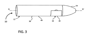
エアロゾル発生システム10は、エアロゾル発生装置12と、マウスピース14と、カートリッジ16とを備える。例示的なエアロゾル発生装置12は、ハウジング20と、保持機構18と、ドアユニット21とを備える。エアロゾル発生装置12およびマウスピース14は、単一の細長いユニットとして一緒に形成されてもよい。エアロゾル発生装置12およびマウスピース14は、分離したユニットとして形成されてもよい。こうした場合、マウスピース14は、エアロゾル発生装置12のハウジング20と螺合的に係合する。
The
以下の文章において、エアロゾル発生装置12およびマウスピース14が別個のユニットとして形成される場合の実施形態が記述されている。この文章で説明される原理は、マウスピースがハウジングと一体型である実施形態に等しく適用可能である。
In the following text, an embodiment is described in which the
エアロゾル発生装置12のハウジング20は、長軸方向軸X-X’に沿って延びる。ハウジング20は、カートリッジ16が中に受容されるチャンバー32を備える。チャンバー32は、ハウジング20のマウスピース端の近位である。チャンバー32は、ハウジング20の内部内に画定されている。ハウジング20は、チャンバー32へのアクセスを可能にする挿入窓34を備える。
The
ハウジング20は、カートリッジチャンバー32および電気構成要素22を備える。ハウジング20は、電気構成要素22を支持し、かつ据え付ける。電気構成要素22は、電源24(例えば、リチウム電池)と、制御回路26と、カートリッジ電気コネクター28とを含む。制御回路26は、電源24およびカートリッジ電気コネクター28の各々と電気的接続している。制御回路26は、電源24からカートリッジ電気コネクター28への電流の供給を選択的に可能にする。カートリッジ電気コネクター28は、チャンバー32の内周30に取り付けられている。カートリッジ電気コネクター28は、カートリッジがチャンバー32内に設置されている時に、カートリッジ16を電源24に接続し、かつ制御回路26に接続する。カートリッジ電気コネクター28は、カートリッジ16への電流の供給を容易にする。
The
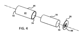
例示的な実施形態において、カートリッジ16は、液体容器46と、メッシュタイプの発熱体48と、液体移動機構50とを備える。メッシュタイプの発熱体48は、液体容器46の一方の端に位置付けられている。液体移動機構50は、メッシュタイプの発熱体48に接触する。
In an exemplary embodiment, the
以下に記述する、カートリッジ16の実施例は、液体容器46と、メッシュタイプの発熱体48と、液体移動機構50とを備える。こうしたカートリッジを図4に示す。この文章で説明される原理は、カートリッジがコイルタイプの発熱体、または当業界で周知の任意の他の霧化要素を備える実施形態に等しく適用可能である。
The
カートリッジ16は、例えば国際特許公開公報第2016/174179号に記載のタイプのものであってもよい。液体容器46は、eリキッドを貯蔵および担持する円筒状の液体貯蔵媒体である。液体容器46は液体移動機構50を包含する。液体容器46は閉端部52および開端部54を有する。液体移動機構50は多孔性浸漬材料で作製されている。液体移動機構50は液体移動端56を含む。液体移動機構50は、液体移動端56が液体容器46の開端部54と当接するように、液体容器46内に同軸に位置付けられている。液体移動機構50は、液体を液体容器46からヒーター48に移動させ、ここで液体はその後気化される。
The
発熱体48は、液体容器46の開端部54の上に配置された平坦なメッシュタイプのヒーターユニットである。発熱体48は液体容器46の開端部54を密封する。発熱体48の少なくとも一つの電気的接続部分58は、液体容器46の外部表面43を超えて延び、その結果、カートリッジ16がエアロゾル発生装置12のカートリッジチャンバー32の中に位置付けられている時に、電気的接続部分58はカートリッジ電気コネクター28に接続する。
The
エアロゾル発生装置12のハウジング20は挿入窓34を形成し、これを通してカートリッジ16、チャンバー32、または両方はアクセス可能である。挿入窓34は、エアロゾル発生装置のハウジング20内の切り抜きとして形成されてもよい(例えば、図1を参照のこと)。挿入窓34は、エアロゾル形成装置12のハウジング20のカートリッジチャンバー32へのアクセスを容易にする。
The
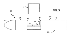
挿入窓34aは、マルチパート分割配設として形成されてもよい。マルチパート分割配設として形成された挿入窓34aを有するエアロゾル発生装置12aが図5に示されている。挿入窓34aは、ハウジング20aの手動改変に伴い開く。ハウジング20aは、第一の摺動部材36と、第二の摺動部材38と、接続部材40とを含む。第一の摺動部材36および第二の摺動部材38は、第一の取り付け端42および第二の取り付け端44をそれぞれ含む。第一の摺動部材36の第一の取り付け端42は、第二の摺動部材38の第二の取り付け端44にスナップ嵌めで取り付けられている。接続部材40は、開口を有する実質的に湾曲したセクションである。接続部材40は、同軸に位置付けられていて、かつ第一の摺動部材36および第二の摺動部材38の各々の少なくとも一部分に摺動可能に取り付けられている。第一の摺動部材36および第二の摺動部材38は、接続部材40に対して摺動するように相互に取り外され、かつ相互から直線的に離されている。第一の摺動部材36および第二の摺動部材38のこうした移動は、カートリッジチャンバー32へのアクセスを容易にする挿入窓34aを形成する。
The
以下の記述において、切り抜き挿入窓34を有する実施形態が記述されている。しかしながら、この文章で説明される原理の多くは、挿入窓がマルチパート分割配設として形成されている実施形態に等しく適用可能である。
In the following description, an embodiment having a cut-out
カートリッジ16をチャンバー32内に保持するために、保持機構18が提供されている。保持機構18は、軸方向のプッシュタイプ保持システム18であってもよい。保持機構18は、半径方向のプッシュタイプ保持システム18bであってもよい。カートリッジ16の構造および配設は、保持機構18の各タイプに対して異なっていてもよい。
A
例示的な軸方向のプッシュタイプ保持システム18は、二つの軸方向ばね60および底部プレート61を備える。軸方向ばね60は、カートリッジチャンバー32内でハウジング20に取り付けられている。底部プレート61は、軸方向ばね60の自由端に取り付けられている。軸方向ばね60および底部プレート61は、軸方向ばね60がエアロゾル発生装置12の長軸方向軸X-X’に沿ってばね作用を促進するように位置付けられている。軸方向ばね60および底部プレート61は、チャンバー32の遠位端に位置付けられている。
The exemplary axial push-
カートリッジ16をチャンバー32の中に設置するために、カートリッジ16の遠位端部分62は当初、挿入窓34を通して、かつチャンバー32の中に押され、その結果遠位端部分62は完全にチャンバー32内に位置付けられている。遠位端部分62は底部プレート61と接触する。次に、カートリッジ16は底部プレート61に対して軸方向に押される。マウスピース端部分64はチャンバー32に入り、かつチャンバー32内に位置付けられている。マウスピース端部分64は、チャンバー32内に位置付けられている。カートリッジ16の外部表面43は、ハウジング20の外部表面49に当接する。電気的接続部分58とカートリッジ電気コネクター28の間の電気的接触が確立され、維持される。
To install the
言い換えれば、カートリッジ16をエアロゾル発生装置12に設置するために、カートリッジ16は当初、エアロゾル発生装置12の挿入窓34を通して押される。カートリッジ16はチャンバー32に入る。次に、カートリッジ16は、チャンバー32を通して摺動するようにさらに押され、ばね60を作動させる。カートリッジ16上に位置付けられた発熱体48の電気的接続部分58は、ハウジング20のカートリッジチャンバー32の中に位置付けられたカートリッジ電気コネクター28と接触する。
In other words, to install the
カートリッジ16をチャンバー32から設置解除するために、カートリッジ16のマウスピース端部分64に、アクセススロットを通して手動でアクセスし、チャンバー32から引き出される。底部プレート61を介した軸方向ばね60のばね作用は、チャンバー32からのカートリッジ16の設置解除を生じさせる。
To release the
例示的な半径方向のプッシュタイプ保持システム18bは、二つの半径方向ばね68と、支持プレート70と、二つの保持レバー72と、排出配設74とを備える。半径方向ばね68は、挿入窓34と反対側のハウジング20bの内周30に取り付けられている。カートリッジ電気コネクター28との半径方向ばね68の接触を回避するために、半径方向ばね68は、カートリッジ電気コネクター28の中の離隔した穴内に位置付けられている。この文脈における離隔した穴は、穴の内周と半径方向ばね68の間に間隙を残すように構成されている穴を意味する。このようにして、カートリッジ電気コネクター28への電流の供給は妨害されない。支持プレート70は、半径方向ばね68の自由端に取り付けられている。
The exemplary radial push-
保持レバー72の各々は、第一の端76および第二の端78を含む。各保持レバー72の第二の端78は、ハウジング20bの内周30に据え付けられている。保持レバー72は、ねじりばね(図示せず)を介してハウジング20に据え付けられている。
Each of the retaining levers 72 includes a
排出配設74は、ばねタイプの作動スイッチ80および二つの押しピン82を含む。作動スイッチ80は、エアロゾル発生装置12bのハウジング20bの外部表面49上に位置付けられている。各押しピン82は、ハウジング20bを通って延びて、各保持レバー72に接触する。作動スイッチ80を押すと、押しピン82は保持押しピンレバー72を押す。保持レバー72のこうした押圧は、保持レバー72の旋回移動を容易にする。これは、カートリッジ16bのノッチ部分84から保持レバー72を係脱するためである(以下に記述)。
The
半径方向のプッシュタイプ保持システムで使用されるカートリッジは、二つのノッチ部分84を備える。ノッチ部分84は、保持レバー72と協働して、カートリッジ16bをチャンバー32の中に保持するように適合されている。
A cartridge used in a radial push type retention system includes two notched portions 84. The notched portions 84 are adapted to cooperate with the
カートリッジ16bをカートリッジチャンバー32の中に設置するために、カートリッジ16bは、挿入窓34を通して半径方向に(すなわち、エアロゾル発生装置12bの長軸方向軸X-X’に対して横断する方向に)押される。カートリッジ16bがチャンバー32の内側に押されると、カートリッジ16bは支持プレート70に接触する。カートリッジ16bは、半径方向ばね68を圧縮するようにさらに押され、その結果各保持レバー72の第一の端76はカートリッジ16bのノッチ部分84と係合する。保持レバー72との、カートリッジ16bのこうした配設は、カートリッジ16bをチャンバー32内に保持する。
To install the
カートリッジチャンバー32からカートリッジ16bを設置解除するために、作動スイッチ80が押される。こうした作動スイッチ80の押圧は、保持レバー72の旋回を生じさせ、これはカートリッジ16bのノッチ部分84からの、保持レバー72の第一の端76の取り外しを生じさせる。次に半径方向ばね68は支持プレート70を押し、これはカートリッジ16bを半径方向に押す。こうした半径方向の押しは、チャンバー32からの、カートリッジ16bの取り外しを生じさせる。
To unseat the
一部の例示的な実施形態において、ハウジング20の周辺窓34を覆い/露出し、カートリッジ16へのアクセスを制限/可能にするために、ドアユニット21が提供されている。ドアユニット21には、挿入窓34が切り抜きとして形成された任意のハウジング20が提供されてもよい。
In some exemplary embodiments, a door unit 21 is provided to cover/expose the
ドアユニット21は、旋回軸を中心として旋回する旋回タイプのドアであってもよい(図10を参照のこと)。ドアユニット21は、ハウジング20の外部表面49に沿って摺動する摺動ドアであってもよい(図11を参照のこと)。ドアユニット21は、ハウジング20から引き離される場合がある引き離しタイプのドアであってもよい(図12を参照のこと)。
The door unit 21 may be a pivot-type door that pivots about a pivot axis (see FIG. 10). The door unit 21 may be a sliding door that slides along the
旋回タイプのドアユニット21cは、周辺窓34の近位にあるハウジング20cに旋回可能に取り付けられている。旋回タイプのドアユニット21cは、ハウジング20cの周辺窓34を通したカートリッジ16cへのアクセスを可能にする/制限するために、旋回軸を中心として旋回する。
The pivoting
摺動ドアユニット21dは、周辺窓34の近位にあるハウジング20dに摺動可能に取り付けられている。摺動ドアユニット21dは、ハウジング20dの周辺窓34を通したカートリッジ16dへのアクセスを可能にする/制限するために、ハウジング20dの長軸方向軸X-X’に沿って摺動する。
The sliding
カートリッジ16eにアクセスすることを可能にするために、引き離しタイプのドアユニット21eがカートリッジチャンバー32から引き出される。カートリッジ16eを交換した後、引き離しドアは、ハウジング20eとスナップ嵌めするようにカートリッジチャンバー32の中の周辺窓34を通して押される。これは、ハウジング20eの周辺窓34を通したカートリッジ16eへのアクセスを制限する。
To allow access to the
上述の特定の実施形態および実施例は本発明を例示するが、本発明を限定しない。本発明の他の実施形態がなされてもよく、また本明細書に記載の具体的な実施形態および実施例は網羅的なものでないことが理解される。 The specific embodiments and examples described above illustrate the invention but do not limit it. It is understood that other embodiments of the invention may be made and that the specific embodiments and examples described herein are not exhaustive.
Claims (9)
ハウジングであって、前記ハウジングが、マウスピース端と、遠位端と、前記マウスピース端と前記遠位端の間の側壁と、前記ハウジング内のチャンバーとを画定し、前記チャンバーが液体容器を受容するように適合されていて、前記ハウジングが、前記液体容器を前記ハウジング内に保持するように適合された保持手段を備え、前記保持手段が磁気保持機構を備え、前記保持手段が、半径方向のプッシュタイプ保持システムをさらに備える、ハウジングと、
前記ハウジング内に位置付けられた電源と、を備え、
前記ハウジングの前記側壁が挿入窓を画定し、この挿入窓を通して液体容器をチャンバーの内側に位置付けることができる、エアロゾル発生装置。 An aerosol generating device, comprising:
a housing defining a mouthpiece end, a distal end, a sidewall between the mouthpiece end and the distal end, and a chamber within the housing, the chamber adapted to receive a liquid container, the housing comprising retention means adapted to retain the liquid container within the housing, the retention means comprising a magnetic retention mechanism, the retention means further comprising a radial push type retention system;
a power source positioned within the housing;
The side wall of the housing defines an insertion window through which a liquid container can be positioned inside the chamber.
請求項1~6のいずれか一項に記載のエアロゾル発生装置と、
液体容器であって、液体エアロゾル形成基体を備える液体容器を備える、エアロゾル発生システム。 1. An aerosol generation system comprising:
An aerosol generating device according to any one of claims 1 to 6,
An aerosol generating system comprising a liquid container, the liquid container comprising a liquid aerosol-forming substrate.
Priority Applications (1)
| Application Number | Priority Date | Filing Date | Title |
|---|---|---|---|
| JP2023157444A JP2023166609A (en) | 2018-04-17 | 2023-09-22 | Aerosol-generating system |
Applications Claiming Priority (3)
| Application Number | Priority Date | Filing Date | Title |
|---|---|---|---|
| EP18167841 | 2018-04-17 | ||
| EP18167841.8 | 2018-04-17 | ||
| PCT/EP2019/060023 WO2019202048A1 (en) | 2018-04-17 | 2019-04-17 | An aerosol-generating system |
Related Child Applications (1)
| Application Number | Title | Priority Date | Filing Date |
|---|---|---|---|
| JP2023157444A Division JP2023166609A (en) | 2018-04-17 | 2023-09-22 | Aerosol-generating system |
Publications (3)
| Publication Number | Publication Date |
|---|---|
| JP2021520799A JP2021520799A (en) | 2021-08-26 |
| JP2021520799A5 JP2021520799A5 (en) | 2022-04-15 |
| JP7666817B2 true JP7666817B2 (en) | 2025-04-22 |
Family
ID=62017274
Family Applications (2)
| Application Number | Title | Priority Date | Filing Date |
|---|---|---|---|
| JP2020555221A Active JP7666817B2 (en) | 2018-04-17 | 2019-04-17 | Aerosol Generation System |
| JP2023157444A Pending JP2023166609A (en) | 2018-04-17 | 2023-09-22 | Aerosol-generating system |
Family Applications After (1)
| Application Number | Title | Priority Date | Filing Date |
|---|---|---|---|
| JP2023157444A Pending JP2023166609A (en) | 2018-04-17 | 2023-09-22 | Aerosol-generating system |
Country Status (6)
| Country | Link |
|---|---|
| US (1) | US12115306B2 (en) |
| EP (1) | EP3781240B1 (en) |
| JP (2) | JP7666817B2 (en) |
| KR (1) | KR102761817B1 (en) |
| CN (1) | CN111918567A (en) |
| WO (1) | WO2019202048A1 (en) |
Families Citing this family (25)
| Publication number | Priority date | Publication date | Assignee | Title |
|---|---|---|---|---|
| CN110403241B (en) * | 2018-04-28 | 2021-02-23 | 深圳御烟实业有限公司 | Aerosol-generating device and system |
| US11838997B2 (en) * | 2018-11-05 | 2023-12-05 | Juul Labs, Inc. | Cartridges for vaporizer devices |
| US20210023315A1 (en) * | 2019-03-29 | 2021-01-28 | Remedio Laboratories, Inc. | Controlled-dose medicinal liquid vaping device |
| EP4114215A1 (en) * | 2020-03-04 | 2023-01-11 | JT International S.A. | Aerosol generation device, and associated removable cartridge and aerosol generation set |
| US11278688B2 (en) * | 2020-03-12 | 2022-03-22 | Max Azevedo | Inhaling device for heavy metal salts and a method of use thereof for medical treatment |
| GB202012179D0 (en) * | 2020-08-05 | 2020-09-16 | Nicoventures Trading Ltd | Aerosol provision device |
| GB202012177D0 (en) * | 2020-08-05 | 2020-09-16 | Nicoventures Trading Ltd | Aerosol provision device |
| EP3981267B1 (en) * | 2020-10-06 | 2023-07-12 | JT International SA | Aerosol generation device with ejection mechanism |
| EP3981268B1 (en) * | 2020-10-06 | 2023-08-23 | JT International SA | Aerosol generation device |
| EP3981266B1 (en) * | 2020-10-06 | 2023-07-19 | JT International SA | Aerosol generation device with ejection mechanism using leverage |
| US11856986B2 (en) * | 2020-10-19 | 2024-01-02 | Rai Strategic Holdings, Inc. | Customizable panel for aerosol delivery device |
| GB202016760D0 (en) * | 2020-10-22 | 2020-12-09 | Nicoventures Trading Ltd | Refilling device |
| WO2022136151A1 (en) * | 2020-12-22 | 2022-06-30 | Philip Morris Products S.A. | Aerosol-generating device with cartridge insertion in a single orientation |
| US12569008B2 (en) | 2021-01-18 | 2026-03-10 | Altria Client Services Llc | Heat-not-burn (HNB) aerosol generating devices and capsules |
| US12011034B2 (en) * | 2021-01-18 | 2024-06-18 | Altria Client Services Llc | Capsules including embedded heaters and heat-not-burn (HNB) aerosol-generating devices |
| KR102579818B1 (en) * | 2021-03-02 | 2023-09-15 | 주식회사 케이티앤지 | Device for generating aerosol |
| US12543784B2 (en) * | 2021-03-24 | 2026-02-10 | Rai Strategic Holdings, Inc. | Aerosol delivery device |
| US12419350B2 (en) * | 2021-09-10 | 2025-09-23 | Imperial Tobacco Limited | Aerosol generating apparatus having a push-push mechanism |
| EP4154739B1 (en) * | 2021-09-27 | 2025-07-30 | Imperial Tobacco Limited | Aerosol generating apparatus |
| GB202202623D0 (en) * | 2022-02-25 | 2022-04-13 | Nicoventures Trading Ltd | Aerosol provision device |
| KR102810442B1 (en) * | 2022-06-17 | 2025-05-23 | 주식회사 케이티앤지 | Aerosol generating device |
| KR102771330B1 (en) * | 2022-09-14 | 2025-02-26 | 주식회사 케이티앤지 | Aerosol generating device |
| EP4727388A1 (en) * | 2023-06-13 | 2026-04-22 | Nicoventures Trading Limited | Aerosol delivery subsystems and methods |
| WO2025229591A1 (en) * | 2024-05-01 | 2025-11-06 | Itc Limited | An enhanced cartridge for efficiently monitoring liquid level in an aerosol generating device |
| CN121445125A (en) * | 2024-07-31 | 2026-02-03 | 爱奇迹创造有限公司 | Heating non-combustion atomizing device and aerosol generating system |
Citations (2)
| Publication number | Priority date | Publication date | Assignee | Title |
|---|---|---|---|---|
| WO2018002994A1 (en) | 2016-06-27 | 2018-01-04 | 日本たばこ産業株式会社 | Cartridge for aerosol inhaler, aerosol inhaler provided with same, and heat-generating sheet for aerosol inhaler |
| WO2018016805A1 (en) | 2016-07-16 | 2018-01-25 | 석인선 | Modularized vaporizer |
Family Cites Families (33)
| Publication number | Priority date | Publication date | Assignee | Title |
|---|---|---|---|---|
| JP2005034021A (en) * | 2003-07-17 | 2005-02-10 | Seiko Epson Corp | Electronic Cigarette |
| CN2760984Y (en) | 2004-06-22 | 2006-03-01 | 李成珠 | Substitution of tobacco smoking |
| DE102012103482A1 (en) * | 2012-04-20 | 2013-10-24 | Alfred Von Schuckmann | Device for inhaling powdery substances |
| US8881737B2 (en) | 2012-09-04 | 2014-11-11 | R.J. Reynolds Tobacco Company | Electronic smoking article comprising one or more microheaters |
| US10058122B2 (en) | 2012-10-25 | 2018-08-28 | Matthew Steingraber | Electronic cigarette |
| US20150367366A1 (en) * | 2012-12-06 | 2015-12-24 | Aerodesigns, Inc. | Aerosol dispenser with edible cartridge |
| WO2014150826A1 (en) | 2013-03-15 | 2014-09-25 | Aerodesigns, Inc. | Aerosol dispenser with edible cartridge |
| CA2866283C (en) * | 2013-09-30 | 2016-02-09 | Darrin B. Farrow | Vaporization device and method of preparation and use |
| US10039321B2 (en) * | 2013-11-12 | 2018-08-07 | Vmr Products Llc | Vaporizer |
| US9451791B2 (en) * | 2014-02-05 | 2016-09-27 | Rai Strategic Holdings, Inc. | Aerosol delivery device with an illuminated outer surface and related method |
| KR20240032162A (en) * | 2014-02-10 | 2024-03-08 | 필립모리스 프로덕츠 에스.에이. | An aerosol-generating system having a heater assembly and a cartridge for an aerosol-generating system having a fluid permeable heater assembly |
| HK1226257A1 (en) * | 2014-02-10 | 2017-09-29 | Philip Morris Products S.A. | An aerosol-generating system comprising a device and a cartridge, in which the device ensures electrical contact with the cartridge |
| SI3166426T1 (en) | 2014-07-11 | 2018-10-30 | Philip Morris Products S.A. | Aerosol-generating system comprising cartridge detection |
| EP3200633B1 (en) | 2014-10-02 | 2025-04-02 | Cue Vapor Ltd | Disposable tank electronic cigarette, method of manufacture and method of use |
| CN107105767B (en) | 2014-11-14 | 2021-01-01 | Jt国际公司 | Containers for smoke generating equipment |
| US20160150828A1 (en) * | 2014-12-02 | 2016-06-02 | Gabriel Marc Goldstein | Vaporizing reservoir |
| CN204560971U (en) | 2015-04-08 | 2015-08-19 | 华健 | A kind of device realizing increasing function of odor on electronic cigarette or tobacco smoke |
| US10602774B2 (en) * | 2015-04-22 | 2020-03-31 | Altria Client Services Llc | E-vapor devices including pre-sealed cartridges |
| PL3288403T3 (en) | 2015-04-30 | 2023-04-24 | Philip Morris Products S.A. | Cartridge for an aerosol-generating system |
| PL3313216T3 (en) * | 2015-06-29 | 2019-07-31 | Philip Morris Products S.A. | Cartridge for an aerosol-generating system |
| JP6882273B2 (en) * | 2015-10-22 | 2021-06-02 | フィリップ・モーリス・プロダクツ・ソシエテ・アノニム | Aerosol generation system |
| US10398178B2 (en) * | 2015-11-06 | 2019-09-03 | Mark Scatterday | Electronic vaporizer |
| PL3167728T3 (en) * | 2015-11-12 | 2020-10-05 | Fontem Holdings 1 B.V. | Electronic smoking device with cavity for liquid reservoir |
| EP3393559B1 (en) * | 2015-12-22 | 2022-03-09 | Philip Morris Products S.A. | Aerosol-generating system with motor |
| GB201605357D0 (en) * | 2016-03-30 | 2016-05-11 | British American Tobacco Co | Apparatus for heating aerosol generating material and a cartridge for the apparatus |
| MX2018011469A (en) | 2016-03-31 | 2019-01-10 | Philip Morris Products Sa | Aerosol generating system with separate capsule and vaporizing unit. |
| GB201615602D0 (en) * | 2016-09-14 | 2016-10-26 | British American Tobacco Investments Ltd | Receptacle Section |
| GB201615601D0 (en) | 2016-09-14 | 2016-10-26 | British American Tobacco Investments Ltd | Receptacle section |
| CN110167367B (en) * | 2017-01-31 | 2023-03-14 | 菲利普莫里斯生产公司 | Aerosol generating device |
| GB201717486D0 (en) | 2017-10-24 | 2017-12-06 | Nicoventures Holdings Ltd | Mechanism for hatch of electronic aerosol provision device |
| WO2020023547A1 (en) * | 2018-07-23 | 2020-01-30 | Wellness Insight Technologies, Inc. | System for analyzing and controlling consumable media dosing information |
| IL267118B (en) * | 2019-06-05 | 2022-01-01 | Kalo Arie | Vaporizing system and disposable capsules for use therewith |
| US11278688B2 (en) * | 2020-03-12 | 2022-03-22 | Max Azevedo | Inhaling device for heavy metal salts and a method of use thereof for medical treatment |
-
2019
- 2019-04-17 JP JP2020555221A patent/JP7666817B2/en active Active
- 2019-04-17 US US17/048,388 patent/US12115306B2/en active Active
- 2019-04-17 CN CN201980021970.0A patent/CN111918567A/en active Pending
- 2019-04-17 KR KR1020207032574A patent/KR102761817B1/en active Active
- 2019-04-17 WO PCT/EP2019/060023 patent/WO2019202048A1/en not_active Ceased
- 2019-04-17 EP EP19717498.0A patent/EP3781240B1/en active Active
-
2023
- 2023-09-22 JP JP2023157444A patent/JP2023166609A/en active Pending
Patent Citations (2)
| Publication number | Priority date | Publication date | Assignee | Title |
|---|---|---|---|---|
| WO2018002994A1 (en) | 2016-06-27 | 2018-01-04 | 日本たばこ産業株式会社 | Cartridge for aerosol inhaler, aerosol inhaler provided with same, and heat-generating sheet for aerosol inhaler |
| WO2018016805A1 (en) | 2016-07-16 | 2018-01-25 | 석인선 | Modularized vaporizer |
Also Published As
| Publication number | Publication date |
|---|---|
| JP2023166609A (en) | 2023-11-21 |
| US20210145050A1 (en) | 2021-05-20 |
| EP3781240A1 (en) | 2021-02-24 |
| JP2021520799A (en) | 2021-08-26 |
| WO2019202048A1 (en) | 2019-10-24 |
| EP3781240C0 (en) | 2024-10-16 |
| CN111918567A (en) | 2020-11-10 |
| KR20210003152A (en) | 2021-01-11 |
| US12115306B2 (en) | 2024-10-15 |
| BR112020019461A2 (en) | 2021-01-05 |
| EP3781240B1 (en) | 2024-10-16 |
| KR102761817B1 (en) | 2025-02-03 |
Similar Documents
| Publication | Publication Date | Title |
|---|---|---|
| JP7666817B2 (en) | Aerosol Generation System | |
| US11388929B2 (en) | Aerosol generating device with securing means | |
| JP7358414B2 (en) | Power system for portable aerosol generators | |
| KR101667124B1 (en) | Extractor for an aerosol-generating device | |
| US12089635B2 (en) | Extractor for an aerosol-generating device | |
| US20170231285A1 (en) | Aerosol-generating device and system | |
| JP2020534857A (en) | Aerosol generator | |
| RU2765361C1 (en) | Aerosol generating device | |
| RU2780738C2 (en) | Aerosol generating system | |
| BR112020019461B1 (en) | Aerosol Generating Device and Aerosol Generating System | |
| WO2023208953A1 (en) | Aerosol provision system | |
| JP7717817B2 (en) | Non-flammable aerosol delivery device | |
| RU2834335C2 (en) | Power supply system for portable aerosol generating device | |
| EP4716480A1 (en) | Aerosol-generating device comprising a set of airflow-regulating valves | |
| CN117979846A (en) | Aerosol generating device | |
| HK1227646B (en) | Power supply system for portable aerosol-generating device |
Legal Events
| Date | Code | Title | Description |
|---|---|---|---|
| A521 | Request for written amendment filed |
Free format text: JAPANESE INTERMEDIATE CODE: A523 Effective date: 20220406 |
|
| A621 | Written request for application examination |
Free format text: JAPANESE INTERMEDIATE CODE: A621 Effective date: 20220406 |
|
| A131 | Notification of reasons for refusal |
Free format text: JAPANESE INTERMEDIATE CODE: A131 Effective date: 20230215 |
|
| A521 | Request for written amendment filed |
Free format text: JAPANESE INTERMEDIATE CODE: A523 Effective date: 20230510 |
|
| A02 | Decision of refusal |
Free format text: JAPANESE INTERMEDIATE CODE: A02 Effective date: 20230606 |
|
| A521 | Request for written amendment filed |
Free format text: JAPANESE INTERMEDIATE CODE: A523 Effective date: 20230922 |
|
| A911 | Transfer to examiner for re-examination before appeal (zenchi) |
Free format text: JAPANESE INTERMEDIATE CODE: A911 Effective date: 20231003 |
|
| A912 | Re-examination (zenchi) completed and case transferred to appeal board |
Free format text: JAPANESE INTERMEDIATE CODE: A912 Effective date: 20231027 |
|
| A521 | Request for written amendment filed |
Free format text: JAPANESE INTERMEDIATE CODE: A523 Effective date: 20241115 |
|
| A61 | First payment of annual fees (during grant procedure) |
Free format text: JAPANESE INTERMEDIATE CODE: A61 Effective date: 20250403 |
|
| R150 | Certificate of patent or registration of utility model |
Ref document number: 7666817 Country of ref document: JP Free format text: JAPANESE INTERMEDIATE CODE: R150 |