JP7551730B2 - Surface estimation method, surface estimation device, and recording medium - Google Patents
Surface estimation method, surface estimation device, and recording medium Download PDFInfo
- Publication number
- JP7551730B2 JP7551730B2 JP2022506992A JP2022506992A JP7551730B2 JP 7551730 B2 JP7551730 B2 JP 7551730B2 JP 2022506992 A JP2022506992 A JP 2022506992A JP 2022506992 A JP2022506992 A JP 2022506992A JP 7551730 B2 JP7551730 B2 JP 7551730B2
- Authority
- JP
- Japan
- Prior art keywords
- points
- region
- image
- dimensional
- unit
- Prior art date
- Legal status (The legal status is an assumption and is not a legal conclusion. Google has not performed a legal analysis and makes no representation as to the accuracy of the status listed.)
- Active
Links
Images








Classifications
-
- G—PHYSICS
- G02—OPTICS
- G02B—OPTICAL ELEMENTS, SYSTEMS OR APPARATUS
- G02B23/00—Telescopes, e.g. binoculars; Periscopes; Instruments for viewing the inside of hollow bodies; Viewfinders; Optical aiming or sighting devices
- G02B23/24—Instruments or systems for viewing the inside of hollow bodies, e.g. fibrescopes
- G02B23/2407—Optical details
- G02B23/2415—Stereoscopic endoscopes
-
- G—PHYSICS
- G01—MEASURING; TESTING
- G01B—MEASURING LENGTH, THICKNESS OR SIMILAR LINEAR DIMENSIONS; MEASURING ANGLES; MEASURING AREAS; MEASURING IRREGULARITIES OF SURFACES OR CONTOURS
- G01B11/00—Measuring arrangements characterised by the use of optical techniques
- G01B11/02—Measuring arrangements characterised by the use of optical techniques for measuring length, width or thickness
- G01B11/026—Measuring arrangements characterised by the use of optical techniques for measuring length, width or thickness by measuring distance between sensor and object
-
- G—PHYSICS
- G01—MEASURING; TESTING
- G01B—MEASURING LENGTH, THICKNESS OR SIMILAR LINEAR DIMENSIONS; MEASURING ANGLES; MEASURING AREAS; MEASURING IRREGULARITIES OF SURFACES OR CONTOURS
- G01B11/00—Measuring arrangements characterised by the use of optical techniques
- G01B11/02—Measuring arrangements characterised by the use of optical techniques for measuring length, width or thickness
- G01B11/03—Measuring arrangements characterised by the use of optical techniques for measuring length, width or thickness by measuring coordinates of points
-
- G—PHYSICS
- G01—MEASURING; TESTING
- G01B—MEASURING LENGTH, THICKNESS OR SIMILAR LINEAR DIMENSIONS; MEASURING ANGLES; MEASURING AREAS; MEASURING IRREGULARITIES OF SURFACES OR CONTOURS
- G01B11/00—Measuring arrangements characterised by the use of optical techniques
- G01B11/24—Measuring arrangements characterised by the use of optical techniques for measuring contours or curvatures
-
- G—PHYSICS
- G06—COMPUTING OR CALCULATING; COUNTING
- G06T—IMAGE DATA PROCESSING OR GENERATION, IN GENERAL
- G06T7/00—Image analysis
- G06T7/0002—Inspection of images, e.g. flaw detection
- G06T7/0012—Biomedical image inspection
-
- G—PHYSICS
- G06—COMPUTING OR CALCULATING; COUNTING
- G06T—IMAGE DATA PROCESSING OR GENERATION, IN GENERAL
- G06T7/00—Image analysis
- G06T7/50—Depth or shape recovery
-
- G—PHYSICS
- G06—COMPUTING OR CALCULATING; COUNTING
- G06T—IMAGE DATA PROCESSING OR GENERATION, IN GENERAL
- G06T7/00—Image analysis
- G06T7/50—Depth or shape recovery
- G06T7/55—Depth or shape recovery from multiple images
- G06T7/593—Depth or shape recovery from multiple images from stereo images
-
- G—PHYSICS
- G06—COMPUTING OR CALCULATING; COUNTING
- G06T—IMAGE DATA PROCESSING OR GENERATION, IN GENERAL
- G06T2207/00—Indexing scheme for image analysis or image enhancement
- G06T2207/10—Image acquisition modality
- G06T2207/10068—Endoscopic image
Landscapes
- Physics & Mathematics (AREA)
- General Physics & Mathematics (AREA)
- Engineering & Computer Science (AREA)
- Computer Vision & Pattern Recognition (AREA)
- Health & Medical Sciences (AREA)
- Theoretical Computer Science (AREA)
- General Health & Medical Sciences (AREA)
- Radiology & Medical Imaging (AREA)
- Optics & Photonics (AREA)
- Surgery (AREA)
- Astronomy & Astrophysics (AREA)
- Medical Informatics (AREA)
- Quality & Reliability (AREA)
- Nuclear Medicine, Radiotherapy & Molecular Imaging (AREA)
- Image Analysis (AREA)
- Length Measuring Devices By Optical Means (AREA)
- Image Processing (AREA)
- Instruments For Viewing The Inside Of Hollow Bodies (AREA)
Description
本発明は、面推定方法、面推定装置、および記録媒体に関する。 The present invention relates to a surface estimation method, a surface estimation device, and a recording medium.
ボイラー、パイプ、および航空機エンジン等の内部の傷および腐食等の観察および検査に工業用の内視鏡装置が使用されている。この内視鏡装置では、多様な観察物を観察および検査するための複数種類の光学アダプターが用意されている。光学アダプターは、内視鏡の先端部分に装着され、かつ交換可能である。このような内視鏡装置を使用した検査において、被写体の欠陥および傷の大きさを定量的に計測したいという要望がある。この要望に応えるために、3次元計測機能が搭載された内視鏡装置が存在する。 Industrial endoscope devices are used to observe and inspect the internal damage and corrosion of boilers, pipes, aircraft engines, etc. For these endoscope devices, several types of optical adapters are available for observing and inspecting a variety of objects. The optical adapters are attached to the tip of the endoscope and are replaceable. In inspections using such endoscope devices, there is a demand for quantitatively measuring the size of defects and damage in the subject. To meet this demand, there are endoscope devices equipped with three-dimensional measurement functions.
例えば、ユーザーによって画像上で指定された点の情報に基づいて被写体の幾何学的な大きさを計測する機能が内視鏡装置に搭載されている。例えば、面基準計測では、ユーザーによって指定された3つ以上の点に基づいて基準面が推定され、かつユーザーによって指定された計測点と基準面との間の3次元距離が計測される。基準面は、被写体の表面を近似する。For example, an endoscope device is equipped with a function for measuring the geometric size of a subject based on information about points specified on an image by a user. For example, in surface-based measurement, a reference plane is estimated based on three or more points specified by the user, and the three-dimensional distance between the measurement point specified by the user and the reference plane is measured. The reference plane approximates the surface of the subject.
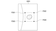
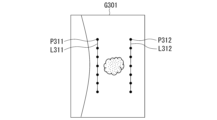
特許文献1に開示された装置は、平面または曲面を基準面として使用し、かつ面基準計測を実行する。図67および図68は、特許文献1における基準面を推定するための3つ以上の点を被写体の画像G301に設定する例を示す。The device disclosed in
図67において、点P301、点P302、点P303、および点P304が画像G301に設定される。4つの点の各々は正方形の頂点に配置されている。図68において、線L311上の2つ以上の点P311および線L312上の2つ以上の点P312が画像G301に設定される。In Fig. 67, points P301, P302, P303, and P304 are set in image G301. Each of the four points is located at a vertex of a square. In Fig. 68, two or more points P311 on line L311 and two or more points P312 on line L312 are set in image G301.
被写体の表面が曲面である場合、特許文献1に開示された装置は基準面を正しく推定できない可能性がある。図69および図70は、誤った基準面が推定される例を示す。If the surface of the subject is curved, the device disclosed in
図69において、点P321、点P322、および点P323が球SP301の表面上に設定される。球SP301をZ軸に平行な方向に見た場合、3つの点の各々は三角形の頂点に配置されている。3つの点のZ方向における高さが同じである場合、3つの点は平面上にある。そのため、その平面が基準面として誤って推定される。In FIG. 69, points P321, P322, and P323 are set on the surface of sphere SP301. When sphere SP301 is viewed in a direction parallel to the Z axis, each of the three points is located at the vertices of a triangle. If the three points have the same height in the Z direction, the three points are on a plane. Therefore, the plane is erroneously estimated as the reference plane.
図70において、線L331および線L332が円筒CY301の表面上に設定され、かつ線L331上の2つ以上の点P331および線L332上の2つ以上の点P332が設定される。線L331および線L332が円筒CY301の中心軸に平行である場合、2つ以上の点P331および2つ以上の点P332は平面上にある。そのため、その平面が基準面として誤って推定される。 In Figure 70, lines L331 and L332 are set on the surface of a cylinder CY301, and two or more points P331 on line L331 and two or more points P332 on line L332 are set. If lines L331 and L332 are parallel to the central axis of cylinder CY301, then two or more points P331 and two or more points P332 are on a plane. Therefore, that plane is erroneously estimated as the reference plane.
本発明は、基準面の精度を向上させることができる面推定方法、面推定装置、および記録媒体を提供することを目的とする。 The present invention aims to provide a surface estimation method, a surface estimation device, and a recording medium that can improve the accuracy of a reference surface.
本発明の第1の態様によれば、面推定方法は、生成ステップ、領域設定ステップ、推定ステップ、および計測ステップを有する。前記生成ステップにおいて、被写体の2次元画像に基づいて前記被写体上の3つ以上の点の3次元座標が算出され、かつ前記3つ以上の点の前記3次元座標を含む3次元画像データが生成される。前記領域設定ステップにおいて、3次元の領域および2次元の領域の一方である基準領域が設定される。前記3次元の領域は、3つ以上の点を含み、かつ3次元空間に設定される。前記3次元空間は、前記3次元画像データに含まれる前記3次元座標を含む。前記2次元の領域は、前記生成ステップにおいて算出された3次元座標が関連付けられた前記2次元画像上の3つ以上の点を含み、かつ前記2次元画像に設定される。前記基準領域の前記3つ以上の点は、三角形を形成する3つの点で構成される1つ以上の組を含む。前記推定ステップにおいて、前記基準領域に含まれる前記3つ以上の点に対応する前記3次元画像データの3つ以上の点に基づいて、前記被写体の表面を近似し前記基準領域と異なる基準面が推定される。前記計測ステップにおいて、前記被写体の前記2次元画像または前記3次元画像データ上の計測点と、前記基準面との3次元距離が計測される。 According to a first aspect of the present invention, a surface estimation method includes a generating step, an area setting step , an estimating step , and a measuring step . In the generating step, three-dimensional coordinates of three or more points on the object are calculated based on a two-dimensional image of the object, and three-dimensional image data including the three-dimensional coordinates of the three or more points is generated. In the area setting step, a reference area that is one of a three-dimensional area and a two-dimensional area is set. The three-dimensional area includes three or more points and is set in a three-dimensional space. The three-dimensional space includes the three-dimensional coordinates included in the three-dimensional image data. The two-dimensional area includes three or more points on the two-dimensional image associated with the three-dimensional coordinates calculated in the generating step , and is set in the two-dimensional image. The three or more points of the reference area include one or more sets of three points forming a triangle. In the estimating step, a reference surface that approximates the surface of the object and is different from the reference area is estimated based on three or more points of the three-dimensional image data corresponding to the three or more points included in the reference area . In the measuring step, a three-dimensional distance between a measurement point on the two-dimensional image or the three-dimensional image data of the subject and the reference surface is measured.
本発明の第2の態様によれば、第1の態様において、前記領域設定ステップにおいて、前記3次元の領域である前記基準領域が前記3次元空間に設定されてもよい。According to a second aspect of the present invention, in the first aspect, in the area setting step, the reference area, which is a three-dimensional area, may be set in the three-dimensional space.
本発明の第3の態様によれば、第1の態様において、前記領域設定ステップにおいて、前記2次元の領域である前記基準領域が前記2次元画像に設定されてもよい。According to a third aspect of the present invention, in the first aspect, in the area setting step, the reference area, which is a two-dimensional area, may be set in the two-dimensional image.
本発明の第4の態様によれば、第2の態様において、前記領域設定ステップにおいて、前記3次元画像データに含まれる前記3次元座標に対応する前記3つ以上の点の連続性が判断されてもよい。前記基準領域は、前記連続性を持つと判断された前記3つ以上の点のみを含んでもよい。According to a fourth aspect of the present invention, in the second aspect, in the region setting step, the continuity of the three or more points corresponding to the three-dimensional coordinates included in the three-dimensional image data may be determined. The reference region may include only the three or more points determined to have the continuity.
本発明の第5の態様によれば、第1の態様において、前記基準領域は、凸集合ではない領域を含んでもよい。According to a fifth aspect of the present invention, in the first aspect, the reference region may include a region that is not a convex set.
本発明の第6の態様によれば、面推定方法は、生成ステップ、領域設定ステップ、および推定ステップを有する。前記生成ステップにおいて、被写体の2次元画像に基づいて前記被写体上の3つ以上の点の3次元座標が算出され、かつ前記3つ以上の点の前記3次元座標を含む3次元画像データが生成される。前記領域設定ステップにおいて、3次元の領域および2次元の領域の一方である基準領域が設定される。前記3次元の領域は、3つ以上の点を含み、かつ3次元空間に設定される。前記3次元空間は、前記3次元画像データに含まれる前記3次元座標を含む。前記2次元の領域は、3つ以上の点を含み、かつ前記2次元画像に設定される。前記基準領域の前記3つ以上の点は、三角形を形成する3つの点で構成される1つ以上の組を含む。前記推定ステップにおいて、前記基準領域に含まれる前記3つ以上の点に対応する前記3次元画像データの3つ以上の点に基づいて、前記被写体の表面を近似する基準面が推定される。前記基準領域は、2つ以上の領域を含んでもよい。 According to a sixth aspect of the present invention , a surface estimation method includes a generating step, a region setting step, and an estimating step. In the generating step, three-dimensional coordinates of three or more points on the object are calculated based on a two-dimensional image of the object, and three-dimensional image data including the three-dimensional coordinates of the three or more points is generated. In the region setting step, a reference region that is one of a three-dimensional region and a two-dimensional region is set. The three-dimensional region includes three or more points and is set in a three-dimensional space. The three-dimensional space includes the three-dimensional coordinates included in the three-dimensional image data. The two-dimensional region includes three or more points and is set in the two-dimensional image. The three or more points of the reference region include one or more sets of three points that form a triangle. In the estimating step, a reference surface that approximates the surface of the object is estimated based on three or more points of the three-dimensional image data that correspond to the three or more points included in the reference region. The reference region may include two or more regions.
本発明の第7の態様によれば、第1の態様において、前記面推定方法は、画像表示ステップ、位置入力ステップ、および状態判断ステップをさらに有してもよい。前記画像表示ステップにおいて、前記3次元画像データの画像および前記2次元画像の一方がディスプレイに表示されてもよい。前記位置入力ステップにおいて、入力装置を通して入力された位置情報が受け付けられてもよい。前記位置情報は、前記ディスプレイに表示された前記3次元画像データの前記画像または前記2次元画像上の位置を示してもよい。前記状態判断ステップにおいて、前記被写体の状態が判断されてもよい。前記領域設定ステップにおいて、前記位置情報が示す前記位置と、前記状態とに基づいて前記基準領域の境界が判断されてもよい。 According to the seventh aspect of the present invention, in the first aspect, the surface estimation method may further include an image display step, a position input step, and a state determination step. In the image display step, one of the image of the three-dimensional image data and the two-dimensional image may be displayed on a display. In the position input step, position information input through an input device may be accepted. The position information may indicate a position on the image of the three-dimensional image data or the two-dimensional image displayed on the display. In the state determination step, the state of the subject may be determined. In the area setting step, the boundary of the reference area may be determined based on the position indicated by the position information and the state.
本発明の第8の態様によれば、面推定方法は、生成ステップ、領域設定ステップ、および推定ステップを有する。前記生成ステップにおいて、被写体の2次元画像に基づいて前記被写体上の3つ以上の点の3次元座標が算出され、かつ前記3つ以上の点の前記3次元座標を含む3次元画像データが生成される。前記領域設定ステップにおいて、3次元の領域および2次元の領域の一方である基準領域が設定される。前記3次元の領域は、3つ以上の点を含み、かつ3次元空間に設定される。前記3次元空間は、前記3次元画像データに含まれる前記3次元座標を含む。前記2次元の領域は、3つ以上の点を含み、かつ前記2次元画像に設定される。前記基準領域の前記3つ以上の点は、三角形を形成する3つの点で構成される1つ以上の組を含む。前記推定ステップにおいて、前記基準領域に含まれる前記3つ以上の点に対応する前記3次元画像データの3つ以上の点に基づいて、前記被写体の表面を近似する基準面が推定される。前記基準領域は、凸集合ではない領域を含む。前記基準領域の境界は、第1の境界と、前記第1の境界よりも内側にある第2の境界とを含んでもよい。 According to an eighth aspect of the present invention , a surface estimation method includes a generating step, a region setting step, and an estimating step. In the generating step, three-dimensional coordinates of three or more points on the object are calculated based on a two-dimensional image of the object, and three-dimensional image data including the three-dimensional coordinates of the three or more points is generated. In the region setting step, a reference region that is one of a three-dimensional region and a two-dimensional region is set. The three-dimensional region includes three or more points and is set in a three-dimensional space. The three-dimensional space includes the three-dimensional coordinates included in the three-dimensional image data. The two-dimensional region includes three or more points and is set in the two-dimensional image. The three or more points of the reference region include one or more sets of three points that form a triangle. In the estimating step, a reference surface that approximates the surface of the object is estimated based on three or more points of the three-dimensional image data that correspond to the three or more points included in the reference region. The reference region includes a region that is not a convex set. The boundary of the reference region may include a first boundary and a second boundary that is located inside the first boundary.
本発明の第9の態様によれば、第6の態様において、前記領域設定ステップにおいて、前記3次元画像データに含まれる前記3次元座標に対応する前記3つ以上の点が2つ以上の領域に分割されてもよい。前記基準領域の境界は、前記2つ以上の領域に含まれる1つ以上の領域の境界を含んでもよい。According to a ninth aspect of the present invention, in the sixth aspect, in the region setting step, the three or more points corresponding to the three-dimensional coordinates included in the three-dimensional image data may be divided into two or more regions. The boundary of the reference region may include the boundary of one or more regions included in the two or more regions.
本発明の第10の態様によれば、第6の態様において、前記基準領域の大きさおよび前記基準領域の位置の少なくとも一方を示す領域情報が記録媒体に予め記録されてもよい。前記領域設定ステップにおいて、前記領域情報に基づいて前記基準領域の前記大きさおよび前記基準領域の前記位置の少なくとも一方が設定されてもよい。According to a tenth aspect of the present invention, in the sixth aspect, area information indicating at least one of the size of the reference area and the position of the reference area may be recorded in advance on a recording medium. In the area setting step, at least one of the size of the reference area and the position of the reference area may be set based on the area information.
本発明の第11の態様によれば、第6の態様において、前記面推定方法は、前記3次元画像データの画像および前記2次元画像の一方をディスプレイに表示する画像表示ステップをさらに有してもよい。前記領域設定ステップにおいて、前記3次元画像データの前記画像または前記2次元画像上の3つ以上の点が入力装置を通して入力されてもよい。前記領域設定ステップにおいて、入力された前記3つ以上の点を含む前記基準領域が設定されてもよい。According to an eleventh aspect of the present invention, in the sixth aspect, the surface estimation method may further include an image display step of displaying one of the image of the three-dimensional image data and the two-dimensional image on a display. In the region setting step, three or more points on the image of the three-dimensional image data or the two-dimensional image may be input through an input device. In the region setting step, the reference region including the three or more input points may be set.
本発明の第12の態様によれば、第11の態様において、前記領域設定ステップにおいて、入力された前記3つ以上の点を結ぶ線分に基づいて前記基準領域が設定されてもよい。According to the 12th aspect of the present invention, in the 11th aspect, in the area setting step, the reference area may be set based on a line segment connecting the three or more input points.
本発明の第13の態様によれば、第6の態様において、前記面推定方法は、前記3次元画像データの画像および前記2次元画像の一方をディスプレイに表示する画像表示ステップをさらに有してもよい。前記領域設定ステップにおいて、ユーザーが前記3次元画像データの前記画像または前記2次元画像において指定した線上の3つ以上の点が入力装置を通して入力されてもよい。前記領域設定ステップにおいて、前記線上の前記3つ以上の点を含む前記基準領域が設定されてもよい。According to a thirteenth aspect of the present invention, in the sixth aspect, the surface estimation method may further include an image display step of displaying one of the image of the three-dimensional image data and the two-dimensional image on a display. In the region setting step, three or more points on a line specified by a user in the image of the three-dimensional image data or the two-dimensional image may be input through an input device. In the region setting step, the reference region including the three or more points on the line may be set.
本発明の第14の態様によれば、第6の態様において、前記推定ステップにおいて、前記基準領域に含まれる4つ以上の点から前記3つ以上の点が選択されてもよい。前記推定ステップにおいて、選択された前記3つ以上の点に対応する前記3次元画像データの3つ以上の点に基づいて、前記基準面が推定されてもよい。According to a fourteenth aspect of the present invention, in the sixth aspect, in the estimation step, the three or more points may be selected from four or more points included in the reference area. In the estimation step, the reference surface may be estimated based on three or more points of the three-dimensional image data corresponding to the three or more selected points.
本発明の第15の態様によれば、第6の態様において、前記面推定方法は、前記3次元画像データの画像および前記2次元画像の一方をディスプレイに表示し、かつ前記基準領域を前記3次元画像データの前記画像または前記2次元画像上に表示する画像表示ステップをさらに有してもよい。According to the fifteenth aspect of the present invention, in the sixth aspect, the surface estimation method may further include an image display step of displaying one of the image of the three-dimensional image data and the two-dimensional image on a display, and displaying the reference area on the image of the three-dimensional image data or the two-dimensional image.
本発明の第16の態様によれば、第6の態様において、前記面推定方法は、前記3次元画像データの画像をディスプレイに表示し、かつ前記基準面の推定に使用された前記3次元画像データの前記3つ以上の点を前記3次元画像データの前記画像上に表示する画像表示ステップをさらに有してもよい。According to the 16th aspect of the present invention, in the 6th aspect, the surface estimation method may further include an image display step of displaying an image of the three-dimensional image data on a display and displaying the three or more points of the three-dimensional image data used in estimating the reference surface on the image of the three-dimensional image data.
本発明の第17の態様によれば、第6の態様において、前記面推定方法は、前記2次元画像をディスプレイに表示し、かつ前記基準面の推定に使用された前記3次元画像データの前記3つ以上の点に対応する3つ以上の点を前記2次元画像上に表示する画像表示ステップをさらに有してもよい。According to the 17th aspect of the present invention, in the 6th aspect, the surface estimation method may further include an image display step of displaying the two-dimensional image on a display and displaying three or more points on the two-dimensional image corresponding to the three or more points of the three-dimensional image data used to estimate the reference surface.
本発明の第18の態様によれば、第6の態様において、前記面推定方法は、分割ステップおよび画像表示ステップをさらに有してもよい。前記分割ステップにおいて、前記3次元画像データに含まれる前記3次元座標に対応する3つ以上の点が2つ以上の領域に分割されてもよい。前記画像表示ステップにおいて、前記3次元画像データの画像および前記2次元画像の一方がディスプレイに表示され、かつ前記2つ以上の領域の画像が前記ディスプレイに表示されてもよいAccording to an eighteenth aspect of the present invention, in the sixth aspect, the surface estimation method may further include a division step and an image display step. In the division step, three or more points corresponding to the three-dimensional coordinates included in the three-dimensional image data may be divided into two or more regions. In the image display step, one of an image of the three-dimensional image data and the two-dimensional image may be displayed on a display, and images of the two or more regions may be displayed on the display.
本発明の第19の態様によれば、第6の態様において、前記面推定方法は、マップ生成ステップおよび画像表示ステップをさらに有してもよい。前記マップ生成ステップにおいて、前記3次元画像データが示す前記被写体の3次元形状における曲率の分布を示す曲率マップが生成されてもよい。前記画像表示ステップにおいて、前記3次元画像データの画像および前記2次元画像の一方がディスプレイに表示され、かつ前記曲率マップの画像が前記ディスプレイに表示されてもよい。According to a nineteenth aspect of the present invention, in the sixth aspect, the surface estimation method may further include a map generation step and an image display step. In the map generation step, a curvature map indicating a distribution of curvature in the three-dimensional shape of the subject represented by the three-dimensional image data may be generated. In the image display step, one of an image of the three-dimensional image data and the two-dimensional image may be displayed on a display, and an image of the curvature map may be displayed on the display.
本発明の第20の態様によれば、第6の態様において、前記面推定方法は、前記3次元画像データの画像および前記2次元画像の一方をディスプレイに表示し、かつ前記基準面に対応する領域を前記3次元画像データの前記画像または前記2次元画像上に表示する画像表示ステップをさらに有してもよい。According to the twentieth aspect of the present invention, in the sixth aspect, the surface estimation method may further include an image display step of displaying one of the image of the three-dimensional image data and the two-dimensional image on a display, and displaying an area corresponding to the reference surface on the image of the three-dimensional image data or the two-dimensional image.
本発明の第21の態様によれば、第6の態様において、前記面推定方法は、前記3次元画像データの画像および前記2次元画像の一方に基づいて前記被写体の前記表面における異常な領域を検出する異常検出ステップをさらに有してもよい。前記領域設定ステップにおいて、前記異常な領域に対応する領域を除く前記基準領域が設定されてもよい。According to a twenty-first aspect of the present invention, in the sixth aspect, the surface estimation method may further include an abnormality detection step of detecting an abnormal area on the surface of the subject based on one of the image of the three-dimensional image data and the two-dimensional image. In the area setting step, the reference area excluding an area corresponding to the abnormal area may be set.
本発明の第22の態様によれば、第6の態様において、前記面推定方法は、前記基準面に基づいて前記被写体の大きさを計測する計測ステップをさらに有してもよい。According to the 22nd aspect of the present invention, in the 6th aspect, the surface estimation method may further include a measurement step of measuring the size of the subject based on the reference surface.
本発明の第23の態様によれば、第22の態様において、前記計測ステップにおいて、前記基準面と前記被写体の前記表面上の点との間の3次元距離が計測されてもよい。According to the 23rd aspect of the present invention, in the 22nd aspect, in the measurement step, a three-dimensional distance between the reference plane and a point on the surface of the subject may be measured.
本発明の第24の態様によれば、第6の態様において、前記推定ステップにおいて、前記基準面の幾何学的な特徴がさらに推定されてもよい。According to the 24th aspect of the present invention, in the 6th aspect, the estimation step may further include estimating geometric characteristics of the reference surface.
本発明の第25の態様によれば、面推定方法は、読み出しステップ、領域設定ステップ、推定ステップ、および計測ステップを有する。前記読み出しステップにおいて、被写体の2次元画像に基づいて算出された前記被写体上の3つ以上の点の3次元座標を含む3次元画像データが記録媒体から読み出される。前記領域設定ステップにおいて、3次元の領域および2次元の領域の一方である基準領域が設定される。前記3次元の領域は、3つ以上の点を含み、かつ3次元空間に設定される。前記3次元空間は、前記3次元画像データに含まれる前記3次元座標を含む。前記2次元の領域は、前記3次元画像データに含まれる3次元座標が関連付けられた前記2次元画像上の3つ以上の点を含み、かつ前記2次元画像に設定される。前記基準領域の前記3つ以上の点は、三角形を形成する3つの点で構成される1つ以上の組を含む。前記推定ステップにおいて、前記基準領域に含まれる前記3つ以上の点に対応する前記3次元画像データの3つ以上の点に基づいて、前記被写体の表面を近似し前記基準領域と異なる基準面が推定される。前記計測ステップにおいて、前記被写体の前記2次元画像または前記3次元画像データ上の計測点と、前記基準面との3次元距離が計測される。 According to a twenty-fifth aspect of the present invention, a surface estimation method includes a reading step, a region setting step , an estimation step , and a measurement step . In the reading step, three-dimensional image data including three-dimensional coordinates of three or more points on the object calculated based on a two-dimensional image of the object is read from a recording medium. In the region setting step, a reference region that is one of a three-dimensional region and a two-dimensional region is set. The three-dimensional region includes three or more points and is set in a three-dimensional space. The three-dimensional space includes the three-dimensional coordinates included in the three-dimensional image data. The two-dimensional region includes three or more points on the two-dimensional image associated with the three-dimensional coordinates included in the three-dimensional image data and is set in the two-dimensional image. The three or more points of the reference region include one or more sets of three points forming a triangle. In the estimation step, a reference surface that approximates the surface of the object and is different from the reference region is estimated based on three or more points of the three-dimensional image data corresponding to the three or more points included in the reference region. In the measuring step, a three-dimensional distance between a measurement point on the two-dimensional image or the three-dimensional image data of the subject and the reference surface is measured.
本発明の第26の態様によれば、面推定装置は、生成部、領域設定部、推定部、および計測部を有する。前記生成部は、被写体の2次元画像に基づいて前記被写体上の3つ以上の点の3次元座標を算出し、かつ前記3つ以上の点の前記3次元座標を含む3次元画像データを生成する。前記領域設定部は、3次元の領域および2次元の領域の一方である基準領域を設定する。前記3次元の領域は、3つ以上の点を含み、かつ3次元空間に設定される。前記3次元空間は、前記3次元画像データに含まれる前記3次元座標を含む。前記2次元の領域は、前記生成部によって算出された3次元座標が関連付けられた前記2次元画像上の3つ以上の点を含み、かつ前記2次元画像に設定される。前記基準領域の前記3つ以上の点は、三角形を形成する3つの点で構成される1つ以上の組を含む。前記推定部は、前記基準領域に含まれる前記3つ以上の点に対応する前記3次元画像データの3つ以上の点に基づいて、前記被写体の表面を近似し前記基準領域と異なる基準面を推定する。前記計測部は、前記被写体の前記2次元画像または前記3次元画像データ上の計測点と、前記基準面との3次元距離を計測する。 According to a twenty-sixth aspect of the present invention, a surface estimation device includes a generating unit, a region setting unit , an estimating unit , and a measuring unit . The generating unit calculates three-dimensional coordinates of three or more points on the object based on a two-dimensional image of the object, and generates three-dimensional image data including the three-dimensional coordinates of the three or more points. The region setting unit sets a reference region that is one of a three-dimensional region and a two-dimensional region. The three-dimensional region includes three or more points, and is set in a three-dimensional space. The three-dimensional space includes the three-dimensional coordinates included in the three-dimensional image data. The two-dimensional region includes three or more points on the two-dimensional image associated with the three-dimensional coordinates calculated by the generating unit , and is set in the two-dimensional image. The three or more points of the reference region include one or more sets of three points forming a triangle. The estimating unit approximates the surface of the object and estimates a reference surface different from the reference region based on three or more points of the three-dimensional image data corresponding to the three or more points included in the reference region . The measurement unit measures a three-dimensional distance between a measurement point on the two-dimensional image or the three-dimensional image data of the subject and the reference plane.
本発明の第27の態様によれば、生成ステップ、領域設定ステップ、推定ステップ、および計測ステップをコンピュータに実行させるためのプログラムが記録されたコンピュータ読み取り可能な記録媒体が提供される。前記生成ステップにおいて、被写体の2次元画像に基づいて前記被写体上の3つ以上の点の3次元座標が算出され、かつ前記3つ以上の点の前記3次元座標を含む3次元画像データが生成される。前記領域設定ステップにおいて、3次元の領域および2次元の領域の一方である基準領域が設定される。前記3次元の領域は、3つ以上の点を含み、かつ3次元空間に設定される。前記3次元空間は、前記3次元画像データに含まれる前記3次元座標を含む。前記2次元の領域は、前記生成ステップにおいて算出された3次元座標が関連付けられた前記2次元画像上の3つ以上の点を含み、かつ前記2次元画像に設定される。前記基準領域の前記3つ以上の点は、三角形を形成する3つの点で構成される1つ以上の組を含む。前記推定ステップにおいて、前記基準領域に含まれる前記3つ以上の点に対応する前記3次元画像データの3つ以上の点に基づいて、前記被写体の表面を近似し前記基準領域と異なる基準面が推定される。前記計測ステップにおいて、前記被写体の前記2次元画像または前記3次元画像データ上の計測点と、前記基準面との3次元距離が計測される。 According to a 27th aspect of the present invention, there is provided a computer-readable recording medium having a program recorded thereon for causing a computer to execute a generating step, an area setting step , an estimating step , and a measuring step . In the generating step, three-dimensional coordinates of three or more points on the object are calculated based on a two-dimensional image of the object, and three-dimensional image data including the three-dimensional coordinates of the three or more points is generated. In the area setting step, a reference area that is one of a three-dimensional area and a two-dimensional area is set. The three-dimensional area includes three or more points and is set in a three-dimensional space. The three-dimensional space includes the three-dimensional coordinates included in the three-dimensional image data. The two-dimensional area includes three or more points on the two-dimensional image associated with the three-dimensional coordinates calculated in the generating step , and is set in the two-dimensional image. The three or more points of the reference area include one or more sets of three points forming a triangle. In the estimating step, a reference surface that approximates the surface of the object and is different from the reference area is estimated based on three or more points of the three-dimensional image data corresponding to the three or more points included in the reference area . In the measuring step, a three-dimensional distance between a measurement point on the two-dimensional image or the three-dimensional image data of the subject and the reference surface is measured.
上記の各態様によれば、面推定方法、面推定装置、および記録媒体は、基準面の精度を向上させることができる。 According to each of the above aspects, the surface estimation method, the surface estimation device, and the recording medium can improve the accuracy of the reference surface.
図面を参照し、本発明の実施形態を説明する。 An embodiment of the present invention is described with reference to the drawings.
(第1の実施形態)
図1は、本発明の第1の実施形態の面推定装置7の構成を示す。図1に示す面推定装置7は、生成部70、領域設定部71、および面推定部72を有する。
First Embodiment
1 shows the configuration of a surface estimating device 7 according to a first embodiment of the present invention. The surface estimating device 7 shown in FIG.
生成部70は、被写体の2次元画像に基づいて被写体上の3つ以上の点の3次元座標を算出し、かつその3つ以上の点の3次元座標を含む点群データ(3次元画像データ)を生成する(生成ステップ)。領域設定部71は、3次元の領域および2次元の領域の一方である基準領域を設定する(領域設定ステップ)。その3次元の領域は、3つ以上の点を含み、かつ3次元空間に設定される。その3次元空間は、点群データに含まれる3次元座標を含む。その2次元の領域は、3つ以上の点を含み、かつ被写体の2次元画像に設定される。基準領域の3つ以上の点は、三角形を形成する3つの点で構成される1つ以上の組を含む。面推定部72は、基準領域に含まれる3つ以上の点に対応する点群データの3つ以上の点に基づいて、被写体の表面を近似する基準面を推定する(推定ステップ)。The generating
図1に示す各部は、プロセッサおよび論理回路の少なくとも1つで構成されてもよい。例えば、プロセッサは、CPU(Central Processing Unit)、DSP(Digital Signal Processor)、およびGPU(Graphics Processing Unit)の少なくとも1つである。例えば、論理回路は、ASIC(Application Specific Integrated Circuit)およびFPGA(Field-Programmable Gate Array)の少なくとも1つである。図1に示す各部は、1つまたは複数のプロセッサを含むことができる。図1に示す各部は、1つまたは複数の論理回路を含むことができる。Each unit shown in FIG. 1 may be composed of at least one of a processor and a logic circuit. For example, the processor is at least one of a CPU (Central Processing Unit), a DSP (Digital Signal Processor), and a GPU (Graphics Processing Unit). For example, the logic circuit is at least one of an ASIC (Application Specific Integrated Circuit) and an FPGA (Field-Programmable Gate Array). Each unit shown in FIG. 1 may include one or more processors. Each unit shown in FIG. 1 may include one or more logic circuits.
面推定装置7のコンピュータがプログラムを読み込み、かつ読み込まれたプログラムを実行してもよい。そのプログラムは、生成部70、領域設定部71、および面推定部72の動作を規定する命令を含む。つまり、生成部70、領域設定部71、および面推定部72の機能はソフトウェアにより実現されてもよい。The computer of the surface estimation device 7 may load a program and execute the loaded program. The program includes instructions that define the operation of the
上記のプログラムは、コンピュータ読み取り可能な記録媒体に記録されてもよい。そのプログラムは、そのプログラムを保持するコンピュータから、伝送媒体を経由して、あるいは伝送媒体中の伝送波により面推定装置7に伝送されてもよい。プログラムを伝送する「伝送媒体」は、情報を伝送する機能を有する媒体である。情報を伝送する機能を有する媒体は、インターネット等のネットワーク(通信網)および電話回線等の通信回線(通信線)を含む。上述したプログラムは、前述した機能の一部を実現してもよい。さらに、上述したプログラムは、差分ファイル(差分プログラム)であってもよい。コンピュータに既に記録されているプログラムと差分プログラムとの組合せが、前述した機能を実現してもよい。The above program may be recorded on a computer-readable recording medium. The program may be transmitted from a computer that holds the program to the surface estimation device 7 via a transmission medium, or by a transmission wave in the transmission medium. A "transmission medium" that transmits the program is a medium that has a function of transmitting information. Media that have a function of transmitting information include networks (communication networks) such as the Internet and communication lines (communication lines) such as telephone lines. The above program may realize some of the functions described above. Furthermore, the above program may be a difference file (difference program). A combination of a program already recorded in a computer and a difference program may realize the functions described above.
図2を使用して、第1の実施形態における面推定処理について説明する。図2は、面推定処理の手順を示す。The surface estimation process in the first embodiment will be described using Figure 2. Figure 2 shows the procedure for the surface estimation process.
生成部70は、被写体の2次元画像(2D画像)に基づいて被写体上の3つ以上の点の3次元座標(3D座標)を算出し、かつその3つ以上の点の3D座標を含む点群データを生成する(ステップS1)。ステップS1は、生成ステップに対応する。The generating
被写体の2D画像がステレオ画像である場合、1枚の2D画像は、第1の視点から見た被写体の画像と、第1の視点と異なる第2の視点から見た被写体の画像とを含む。生成部70は、その2D画像の各画素に対応する3D座標を算出する。生成部70は、被写体上の3つ以上の点の3D座標を含む点群データを生成する。点群データにおいて3つ以上の点の各々の3D座標は2D画像上の点と関連付けられている。具体的には、点群データにおける3D座標は、2D画像上の画素と関連付けられている。例えば、点群データは、3D座標と、2D画像上の画素の位置情報とを含む。When the 2D image of the subject is a stereo image, one 2D image includes an image of the subject seen from a first viewpoint and an image of the subject seen from a second viewpoint different from the first viewpoint. The
生成部70は、2枚以上の画像を使用することにより、かつSfM(Structure from Motion)を適用することにより、被写体上の3つ以上の点の3D座標を算出してもよい。生成部70は、空間的な位相が互いに異なる2つ以上の縞パターンが投影された被写体の2枚以上の2D画像を使用することにより、かつ位相シフト法を適用することにより、被写体上の3つ以上の点の3D座標を算出してもよい。生成部70は、明部および暗部がランダムに配置されたパターン光が照射された被写体の1枚の2D画像を使用することにより、被写体上の3つ以上の点の3D座標を算出してもよい。点群データを生成する方法は上記の方法に限らない。The generating
生成部70は、点群データをディスプレイに表示するための3次元画像(3D画像)を生成してもよい。3D画像は、点群データが示す3次元形状(3D形状)の画像である。3D画像は、各画素のカラーデータを含む。3D画像の各画素は、3D座標と関連付けられている。生成部70は、互いに異なる2つ以上の視点の各々に対応する3D画像を生成してもよい。The generating
ステップS1の後、領域設定部71は、3次元の領域および2次元の領域の一方である基準領域を設定する(ステップS2)。ステップS2は、領域設定ステップに対応する。After step S1, the
図3は、点群データの3D画像の例を示す。生成部70は、点群データをメッシュデータに変換し、かつそのメッシュデータにテクスチャを付加する。生成部70は、この処理を実行することにより3D画像G1を生成する。生成部70は、点群データをメッシュデータに変換せずに3D画像を生成してもよい。
Figure 3 shows an example of a 3D image of point cloud data. The
3D画像G1において、テクスチャが付加された点群データPD1が示されている。図3に示す例では、領域設定部71は3次元の基準領域R1を設定する。基準領域R1は立方体であり、体積を持つ。基準領域R1は、直方体、球、または円筒などであってもよい。基準領域R1の形状はこれらの例に限らない。In the 3D image G1, point cloud data PD1 with texture added is shown. In the example shown in FIG. 3, the
生成部70は、入力装置を通して入力された情報に基づいて、基準領域R1の位置および基準領域R1の大きさの少なくとも一方を設定する。あるいは、生成部70は、基準領域R1の位置および基準領域R1の大きさの少なくとも一方を自動で設定する。図3に示す例では、基準領域R1を説明するために3D画像G1が使用される。生成部70が3D画像G1を生成する必要はない。The generating
図4は、3次元空間(3D空間)における点群データを模式的に示す。点群データの3D座標は、3D空間SP1において定義され、かつX座標、Y座標、およびZ座標を含む。点群データにおける2つ以上の点CP1が図4に示されている。図4に示す例では、領域設定部71は3次元の基準領域R2を3D空間SP1に設定する。基準領域R2は、点群データにおける3つ以上の点CP1を含む。基準領域R2における3つ以上の点CP1は3次元状に広がる。
Figure 4 shows a schematic diagram of point cloud data in a three-dimensional space (3D space). The 3D coordinates of the point cloud data are defined in the 3D space SP1 and include an X coordinate, a Y coordinate, and a Z coordinate. Two or more points CP1 in the point cloud data are shown in Figure 4. In the example shown in Figure 4, the
基準領域R2における3つ以上の点CP1は、三角形を形成する3つの点で構成される1つ以上の組を含む。例えば、基準領域R2における点CP1a、点CP1b、および点CP1cは三角形T1を形成する。基準領域R2において、三角形を形成する3つの点で構成される多くの組が存在する。The three or more points CP1 in the reference region R2 include one or more sets of three points that form a triangle. For example, points CP1a, CP1b, and CP1c in the reference region R2 form a triangle T1. There are many sets of three points that form a triangle in the reference region R2.
3D空間SP1における任意の仮想直線が基準領域R2における1つ以上の点CP1を通る場合であっても、その仮想直線が通らない1つ以上の点CP1が基準領域R2内に必ず存在する。図4において、仮想直線L1および仮想直線L2が示されている。仮想直線L1および仮想直線L2の各々は、基準領域R2における3つ以上の点CP1のうちの一部のみを通る。基準領域R2を通る任意の仮想直線は、基準領域R2における3つ以上の点CP1のうちの一部のみを通る。Even if any virtual line in the 3D space SP1 passes through one or more points CP1 in the reference region R2, there are always one or more points CP1 in the reference region R2 through which the virtual line does not pass. In FIG. 4, virtual lines L1 and L2 are shown. Each of the virtual lines L1 and L2 passes through only a portion of the three or more points CP1 in the reference region R2. Any virtual line that passes through the reference region R2 passes through only a portion of the three or more points CP1 in the reference region R2.
図5は、被写体の2D画像の例を示す。図5に示す例では、領域設定部71は2次元の基準領域R3を被写体の2D画像G2に設定する。基準領域R3は正方形であり、面積を持つ。基準領域R3は、3つ以上の頂点を持つ多角形であってもよい。基準領域R3は、円または楕円などであってもよい。基準領域R3の形状はこれらの例に限らない。
Figure 5 shows an example of a 2D image of a subject. In the example shown in Figure 5, the
生成部70は、入力装置を通して入力された情報に基づいて、基準領域R3の位置および基準領域R3の大きさの少なくとも一方を設定する。あるいは、生成部70は、基準領域R3の位置および基準領域R3の大きさの少なくとも一方を自動で設定する。The generating
基準領域R3は、被写体の表面上の3つ以上の点を含む。被写体の2D画像上の点は、点群データにおける点の3D座標と関連付けられている。そのため、基準領域R3における3つ以上の点の各々は、点群データにおける点の3D座標と関連付けられている。基準領域R3における3つ以上の点は2次元状に広がる。そのため、基準領域R3の3つ以上の点に対応する点群データの3つ以上の点は3次元状に広がる。 The reference region R3 includes three or more points on the surface of the subject. The points on the 2D image of the subject are associated with the 3D coordinates of a point in the point cloud data. Thus, each of the three or more points in the reference region R3 is associated with the 3D coordinates of a point in the point cloud data. The three or more points in the reference region R3 extend in two dimensions. Thus, the three or more points in the point cloud data that correspond to the three or more points in the reference region R3 extend in three dimensions.
ステップS2の後、面推定部72は、基準領域に含まれる3つ以上の点に対応する点群データの3つ以上の点に基づいて、被写体の表面を近似する基準面を推定する(ステップS3)。ステップS3は、推定ステップに対応する。ステップS3が実行されたとき、面推定処理が終了する。After step S2, the
基準領域が3次元の領域である場合、基準領域は点群データにおける3つ以上の点を含む。面推定部72は、その3つ以上の点の各々の3D座標を点群データから取得する。面推定部72は、基準領域における3つ以上の点の3D座標に基づいて基準面を推定する。When the reference region is a three-dimensional region, the reference region includes three or more points in the point cloud data. The
基準領域が2次元の領域である場合、基準領域は被写体の2D画像上の3つ以上の点を含む。被写体の2D画像上の点は、点群データにおける点の3D座標と関連付けられている。面推定部72は、基準領域における3つ以上の点の各々と関連付けられた3D座標を点群データから取得する。面推定部72は、基準領域における3つ以上の点に対応する点群データの3つ以上の点の3D座標に基づいて基準面を推定する。When the reference region is a two-dimensional region, the reference region includes three or more points on the 2D image of the subject. The points on the 2D image of the subject are associated with 3D coordinates of points in the point cloud data. The
例えば、面推定部72は、最小二乗法を使用することにより、平面である基準面を推定する。面推定部72は、RANSAC(Random Sample Consensus)のようなロバスト推定のアルゴリズムを使用することにより基準面を推定してもよい。面推定部72は、Deep Learningのような機械学習を使用することにより基準面を推定してもよい。基準面は、球面、円筒面、または2次曲面などであってもよい。面推定部72が平面を推定する場合、基準領域は3つ以上の点を含む。面推定部72が球面を推定する場合、基準領域は4つ以上の点を含む。面推定部72が円筒面を推定する場合、基準領域は5つ以上の点を含む。基準面の形状は上記の例に限らない。For example, the
面推定装置7は、生成部70の代わりに、被写体の2次元画像に基づいて算出された被写体上の3つ以上の点の3次元座標を含む点群データを記録媒体から読み出す読み出し部を有してもよい。読み出し部は、図2に示すステップS1を実行せずに、点群データを記録媒体から読み出してもよい(読み出しステップ)。生成部70と同様の機能を有する処理部は、点群データを生成し、記録媒体に点群データを記録する。面推定装置7と異なる装置が処理部を有してもよい。Instead of the generating
第1の実施形態において、面推定装置7は、3次元または2次元の基準領域を設定する。基準領域は、3次元状または2次元状に広がる3つ以上の点を含む。そのため、基準面の推定に使用される点群データの3つ以上の点が平面上または直線上で偏って位置する可能性が減る。したがって、面推定装置7は、基準面の精度を向上させることができる。In the first embodiment, the surface estimation device 7 sets a three-dimensional or two-dimensional reference area. The reference area includes three or more points that extend in a three-dimensional or two-dimensional manner. This reduces the possibility that three or more points of the point cloud data used to estimate the reference surface are unevenly positioned on a plane or a straight line. Therefore, the surface estimation device 7 can improve the accuracy of the reference surface.
(第2の実施形態)
本発明の第2の実施形態を説明する。以下では、面推定装置が内視鏡装置である例を説明する。面推定装置は、面推定機能を有する装置でありさえすればよく、内視鏡装置に限らない。面推定装置は、特定の装置またはシステムに実装された組み込み機器であってもよい。面推定装置は、クラウド上の環境であってもよい。被写体は、工業製品である。
Second Embodiment
A second embodiment of the present invention will be described. In the following, an example will be described in which the surface estimation device is an endoscope device. The surface estimation device is not limited to an endoscope device as long as it is a device having a surface estimation function. The surface estimation device may be an embedded device implemented in a specific device or system. The surface estimation device may be an environment on a cloud. The subject is an industrial product.
図6は、第2の実施形態の内視鏡装置1の外観を示す。図7は、内視鏡装置1の内部構成を示す。内視鏡装置1は、被写体を撮像し、画像を生成する。検査者は、種々の被写体の観察を実施するために、挿入部2の先端に装着される光学アダプターの交換と、内蔵された映像処理プログラムの選択と、映像処理プログラムの追加とを実施することが可能である。
Figure 6 shows the external appearance of the
図6に示す内視鏡装置1は、挿入部2、本体部3、操作部4、および表示部5を有する。The
挿入部2は、被写体の内部に挿入される。挿入部2は、先端20から基端部にわたって屈曲可能な細長い管状である。挿入部2は、被写体を撮像し、かつ撮像信号を本体部3に出力する。挿入部2の先端20には、光学アダプターが装着される。例えば、単眼の光学アダプターが挿入部2の先端20に装着される。本体部3は、挿入部2を収納する収納部を備えた制御装置である。操作部4は、内視鏡装置1に対するユーザーの操作を受け付ける。表示部5は、表示画面を有し、かつ挿入部2で取得された被写体の画像および操作メニュー等を表示画面に表示する。The insertion section 2 is inserted into the subject. The insertion section 2 is a long, thin tube that is bendable from the
操作部4は、ユーザーインタフェース(入力装置)である。例えば、操作部4は、ボタン、スイッチ、キー、マウス、ジョイスティック、タッチパッド、トラックボール、およびタッチパネルの少なくとも1つである。表示部5は、LCD(Liquid Crystal Display)等のモニタ(ディスプレイ)である。表示部5は、タッチパネルであってもよい。その場合、操作部4および表示部5は一体化される。ユーザーは、体の一部(例えば、指)または道具を使用することにより表示部5の画面をタッチする。The
図7に示す本体部3は、内視鏡ユニット8、CCU(Camera Control Unit)9、および制御装置10を有する。内視鏡ユニット8は、図示していない光源装置および湾曲装置を有する。光源装置は、観察に必要な照明光を供給する。湾曲装置は、挿入部2に内蔵された湾曲機構を湾曲させる。挿入部2の先端20には撮像素子28が内蔵されている。撮像素子28は、イメージセンサである。撮像素子28は、光学アダプターによって形成された被写体の光学像を光電変換し、かつ撮像信号を生成する。CCU9は、撮像素子28を駆動する。撮像素子28から出力された撮像信号がCCU9に入力される。CCU9は、撮像素子28により取得された撮像信号に対して、増幅およびノイズ除去等を含む前処理を施す。CCU9は、前処理が施された撮像信号をNTSC信号等の映像信号に変換する。
The
制御装置10は、映像信号処理回路12、ROM(Read Only Memory)13、RAM(Random Access Memory)14、カードインタフェース15、外部機器インタフェース16、制御インタフェース17、およびCPU(Central Processing Unit)18を有する。The
映像信号処理回路12は、CCU9から出力された映像信号に対して、所定の映像処理を施す。例えば、映像信号処理回路12は、視認性向上に関わる映像処理を実行する。例えば、その映像処理は、色再現、階調補正、ノイズ抑制、および輪郭強調などである。映像信号処理回路12は、CCU9から出力された映像信号と、CPU18によって生成されたグラフィック画像信号とを合成する。グラフィック画像信号は、操作画面の画像および計測情報等を含む。計測情報は、点群データの3D画像または計測結果等を含む。映像信号処理回路12は、合成された映像信号を表示部5に出力する。また、映像信号処理回路12は、CCU9から出力された映像信号に基づく画像データをCPU18に出力する。The video
ROM13は、CPU18が内視鏡装置1の動作を制御するためのプログラムが記録された不揮発性の記録媒体である。RAM14は、CPU18が内視鏡装置1の制御のために使用する情報を一時的に記憶する揮発性の記録媒体である。CPU18は、ROM13に記録されたプログラムに基づいて内視鏡装置1の動作を制御する。
着脱可能な記録媒体であるメモリカード42がカードインタフェース15に接続される。カードインタフェース15は、メモリカード42に記憶されている制御処理情報および画像情報等を制御装置10に取り込む。また、カードインタフェース15は、内視鏡装置1によって生成された制御処理情報および画像情報等をメモリカード42に記録する。A
USB機器等の外部機器が外部機器インタフェース16に接続される。例えば、パーソナルコンピュータ(PC)41が外部機器インタフェース16に接続される。外部機器インタフェース16は、PC41へ情報を送信し、かつPC41から情報を受信する。これによって、PC41のモニタが情報を表示することができる。また、ユーザーは、PC41に指示を入力することにより、内視鏡装置1の制御に関する操作を実施することができる。An external device such as a USB device is connected to the
制御インタフェース17は、操作部4、内視鏡ユニット8、およびCCU9と動作制御のための通信を実行する。制御インタフェース17は、ユーザーによって操作部4に入力された指示をCPU18に通知する。制御インタフェース17は、光源装置および湾曲装置を制御するための制御信号を内視鏡ユニット8に出力する。制御インタフェース17は、撮像素子28を制御するための制御信号をCCU9に出力する。The
CPU18が実行するプログラムは、コンピュータ読み取り可能な記録媒体に記録されてもよい。この記録媒体に記録されたプログラムを内視鏡装置1以外のコンピュータが読み込み、かつ実行してもよい。例えば、PC41がプログラムを読み込んで実行してもよい。PC41は、プログラムに従って、内視鏡装置1を制御するための制御情報を内視鏡装置1に送信することにより内視鏡装置1を制御してもよい。あるいは、PC41は、内視鏡装置1から映像信号を取得し、かつ取得された映像信号を処理してもよい。The program executed by the
上記のように、内視鏡装置1は、撮像素子28およびCPU18を有する。撮像素子28は、被写体を撮像し、かつ撮像信号を生成する。撮像信号は、被写体の画像を含む。したがって、撮像素子28は、被写体を撮像することにより生成された、その被写体の画像を取得する。撮像素子28によって取得された画像は映像信号処理回路12を経由してCPU18に入力される。As described above, the
撮像素子28は、被写体の画像を取得する画像取得部の機能を有する。画像取得部は、画像入力装置であってもよい。例えば、PC41が面推定装置として動作する場合、画像取得部は、内視鏡装置1と通信を実行する通信インタフェース(通信機)である。画像取得部は無線通信機であってもよい。画像取得部は、画像が記録された記録媒体から画像を読み出す読み出し回路であってもよい。The
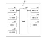
図8は、CPU18の機能構成を示す。制御部180、生成部181、領域設定部182、表示制御部183、位置算出部184、点設定部185、および面推定部186によってCPU18の機能が構成されている。図8に示すブロックの少なくとも1つがCPU18とは別の回路で構成されてもよい。
Figure 8 shows the functional configuration of
図8に示す各部は、プロセッサおよび論理回路の少なくとも1つで構成されてもよい。図8に示す各部は、1つまたは複数のプロセッサを含むことができる。図8に示す各部は、1つまたは複数の論理回路を含むことができる。Each unit shown in FIG. 8 may be composed of at least one of a processor and a logic circuit. Each unit shown in FIG. 8 may include one or more processors. Each unit shown in FIG. 8 may include one or more logic circuits.
制御部180は、被写体の2D画像(画像データ)を映像信号処理回路12から取得し、かつ図8に示す各部が実行する処理を制御する。The
生成部181は、図1に示す生成部70の機能と同じ機能を持つ。生成部181は、被写体の2D画像に基づいて被写体上の3つ以上の点の3D座標を算出し、かつその3つ以上の点の3D座標を含む点群データを生成する(生成ステップ)。生成部181は、第1の実施形態で説明した方法と同じ方法で点群データを生成することができる。また、生成部181は、点群データを表示部5に表示するための3D画像を生成する。The generating
領域設定部182は、図1に示す領域設定部71と同じ機能を持つ。領域設定部182は、3次元の領域および2次元の領域の一方である基準領域を設定する(領域設定ステップ)。領域設定部182は、第1の実施形態で説明した方法と同じ方法で基準領域を設定することができる。The
表示制御部183は、撮像素子28によって取得された被写体の2D画像と、生成部181によって生成された点群データの3D画像とを表示部5に表示する。例えば、表示制御部183は、映像信号処理回路12によって実行される処理を制御する。表示制御部183は、映像信号処理回路12によって処理された映像信号を映像信号処理回路12から表示部5へ出力させる。その映像信号は、被写体の2D画像の各画素のカラーデータを含む。表示部5は、映像信号処理回路12から出力された映像信号に基づいて被写体の2D画像を表示する。The
あるいは、表示制御部183は、3D映像信号を、映像信号処理回路12を経由して表示部5へ出力する。3D映像信号は、点群データの3D画像の各画素のカラーデータを含む。表示部5は、映像信号処理回路12から出力された3D映像信号に基づいて点群データの3D画像を表示する。具体的には、表示制御部183は、点群データの3D画像を表示するためのグラフィック画像信号を生成する。表示制御部183は、生成されたグラフィック画像信号を映像信号処理回路12に出力する。映像信号処理回路12は、CCU9から出力された映像信号と、CPU18から出力されたグラフィック画像信号とを合成する。映像信号処理回路12は、合成された映像信号を表示部5に出力する。表示部5は、被写体の2D画像および点群データの3D画像を表示する。Alternatively, the
表示制御部183は、各種情報を表示部5に表示する。つまり、表示制御部183は、画像上に各種情報を表示する。各種情報は、計測結果等を含む。各種情報は、カーソルを含んでもよい。カーソルは、ユーザーが画像上の特定の点を指定するためのマークである。The
例えば、表示制御部183は、各種情報のグラフィック画像信号を生成する。表示制御部183は、生成されたグラフィック画像信号を映像信号処理回路12に出力する。映像信号処理回路12は、CCU9から出力された映像信号と、CPU18から出力されたグラフィック画像信号とを合成する。これにより、各種情報が画像に重畳される。映像信号処理回路12は、合成された映像信号を表示部5に出力する。表示部5は、各種情報が重畳された画像を表示する。For example, the
ユーザーは、操作部4を操作することにより、画像上の位置を示す位置情報を操作部4に入力する。操作部4は、ユーザーが操作部4に入力した位置情報を出力する。操作部4に入力された位置情報は、入力部である制御インタフェース17に入力される。その位置情報は、制御インタフェース17からCPU18に出力される。位置算出部184は、操作部4に入力された位置情報に基づいて画像上の位置を算出する。
By operating the
例えば、カーソルが画像上に表示される場合、位置情報は、カーソルが表示される位置を示す。表示制御部183は、位置算出部184によって算出された位置にカーソルを表示する。For example, when a cursor is displayed on an image, the position information indicates the position at which the cursor is to be displayed. The
表示部5および操作部4がタッチパネルである場合、ユーザーは表示部5の画面をタッチすることにより画像上の位置を操作部4に入力してもよい。その場合、操作部4は、その位置を示す位置情報を出力する。If the
点設定部185は、被写体上の点を、操作部4を通して受け付ける。例えば、ユーザーは、カーソルを画像上の所望の位置に移動させ、かつ所定の操作を実行する。このとき、点設定部185は、その位置に対応する点を受け付ける。表示部5および操作部4がタッチパネルである場合、ユーザーは表示部5の画面をタッチすることにより画像上の点を操作部4に入力する。点設定部185は、その点を受け付ける。点設定部185は、受け付けられた点を示す点情報を生成する。The
点設定部185が被写体の2D画像上の点を受け付けた場合、点情報はその点に対応する画素の座標を含む。その画素の座標は、点群データにおける3D座標と関連付けられている。点設定部185が点群データの3D画像上の点を受け付けた場合、点情報はその点の3D座標を含む。When the
点設定部185は、基準点を受け付ける。基準点は、基準領域を設定するための基準位置を示す。The
点設定部185が被写体の2D画像上の点を受け付けた場合、点設定部185は、受け付けられた点をその2D画像に設定する。点設定部185が点群データの3D画像上の点を受け付けた場合、点設定部185は、受け付けられた点をその3D画像に設定する。点設定部185によって設定された点の位置情報は、RAM14に保持される。点が特定の画像に関連付けられることにより、その点が設定される。When the
面推定部186は、基準領域に含まれる3つ以上の点に対応する点群データの3つ以上の点に基づいて、被写体の表面を近似する基準面を推定する(推定ステップ)。面推定部186は、第1の実施形態で説明した方法と同じ方法で基準面を推定することができる。The
図9を使用することにより、第2の実施形態における面推定処理について説明する。図9は、面推定処理の手順を示す。 We will explain the surface estimation process in the second embodiment by using Figure 9. Figure 9 shows the steps of the surface estimation process.
生成部181は、被写体の2D画像に基づいて被写体上の3つ以上の点の3D座標を算出し、かつその3つ以上の点の3D座標を含む点群データを生成する。また、生成部181は、点群データの3D画像を生成する(ステップS101)。ステップS101は、生成ステップに対応する。The generating
ステップS101の後、表示制御部183は、被写体の2D画像および点群データの3D画像を表示部5に表示する(ステップS102)。表示制御部183は、被写体の2D画像のみを表示部5に表示してもよい。After step S101, the
図10は、ステップS102において表示部5に表示される画像の例を示す。被写体の2D画像G11および点群データの3D画像G12が表示部5に表示される。3D画像G12の視点を変更する指示が操作部4を通して入力された場合、生成部181は、変更された視点から見た被写体に対応する点群データの新たな3D画像を生成してもよい。表示制御部183は、3D画像G12の代わりにその新たな3D画像を表示部5に表示してもよい。
Figure 10 shows an example of an image displayed on the
図10に示す例では、2D画像G11および3D画像G12が表示部5の画面の水平方向に並べられている。2D画像G11および3D画像G12の配置は、この例に限らない。例えば、2D画像G11および3D画像G12が表示部5の画面の垂直方向に並べられてもよい。このとき、2D画像G11および3D画像G12は90度回転してもよい。2D画像G11の一部および3D画像G12の一部が互いに重なってもよい。In the example shown in FIG. 10, the 2D image G11 and the 3D image G12 are arranged in the horizontal direction on the screen of the
被写体の2D画像がステレオ画像である場合、その2D画像は、第1の視点から見た被写体の第1の画像と、第1の視点と異なる第2の視点から見た被写体の第2の画像とを含む。表示制御部183は、第1の画像および第2の画像を表示部5に表示してもよい。あるいは、表示制御部183は、第1の画像および第2の画像の一方のみを表示部5に表示してもよい。
When the 2D image of the subject is a stereo image, the 2D image includes a first image of the subject seen from a first viewpoint and a second image of the subject seen from a second viewpoint different from the first viewpoint. The
ステップS102の後、点設定部185は、被写体の2D画像上の2つの基準点を、操作部4を通して受け付け、かつ受け付けられた2つの基準点の各々を示す点情報を生成する(ステップS103)。After step S102, the
図11は、ステップS103において表示部5に表示される画像の例を示す。図10に示す2D画像G11と同じ2D画像G11および図10に示す3D画像G12と同じ3D画像G12が表示部5に表示される。
Figure 11 shows an example of an image displayed on the
カーソルが2D画像G11上に表示される例では、ユーザーは、カーソルを2D画像G11上の所望の位置に移動させ、かつ所定の操作を実行する。このとき、点設定部185は、その位置に対応する点を受け付ける。表示部5および操作部4がタッチパネルである例では、ユーザーは表示部5の画面をタッチする。このとき、点設定部185は、タッチされた位置に対応する点を受け付ける。In an example in which the cursor is displayed on the 2D image G11, the user moves the cursor to a desired position on the 2D image G11 and performs a predetermined operation. At this time, the
図11に示す例では、点設定部185は基準点P11および基準点P12を受け付ける。基準点P11を示すマークおよび基準点P12を示すマークが2D画像G11上に表示されてもよい。11, the
ステップS103の後、領域設定部182は、点情報が示す2つの基準点に基づいて基準領域を設定する(ステップS104)。ステップS104は、領域設定ステップに対応する。After step S103, the
領域設定部182は、2次元の基準領域を被写体の2D画像に設定する。例えば、領域設定部182は、図11に示す基準点P11および基準点P12に基づいて基準領域R11を2D画像G11に設定する。図11に示す例では、基準領域R11の形状は長方形である。基準点P11および基準点P12は、基準領域R11の対角線上の頂点である。The
領域設定部182によって設定された基準領域の情報は、RAM14に保持される。その情報は、基準領域の位置および基準領域の大きさを含む。基準領域が被写体の2D画像に関連付けられることにより、その基準領域が設定される。Information about the reference area set by the
ステップS104の後、表示制御部183は、基準領域を被写体の2D画像上に表示する(ステップS105)。After step S104, the
具体的には、表示制御部183は、基準領域を表示するためのグラフィック画像信号を生成する。表示制御部183は、生成されたグラフィック画像信号を映像信号処理回路12に出力する。映像信号処理回路12は、CCU9から出力された映像信号と、CPU18から出力されたグラフィック画像信号とを合成する。映像信号処理回路12は、合成された映像信号を表示部5に出力する。表示部5は、基準領域が重畳された被写体の2D画像を表示する。
Specifically, the
図12は、ステップS105において表示部5に表示される画像の例を示す。図10に示す2D画像G11と同じ2D画像G11および図10に示す3D画像G12と同じ3D画像G12が表示部5に表示される。基準領域R11が2D画像G11上に表示される。
Figure 12 shows an example of an image displayed on the
図12に示す例では、基準領域R11の輪郭を示す線(枠)が2D画像G11上に表示される。図12に示す例では、基準領域R11内の被写体の表面が視認できる。基準領域R11の内側が所定の色または模様で表示されてもよい。このとき、基準領域R11内の被写体の表面が視認できなくてもよい。ユーザーが基準領域R11の位置および大きさを確認できる限り、基準領域R11を表示する方法は上記の方法に限らない。In the example shown in FIG. 12, a line (frame) indicating the outline of the reference region R11 is displayed on the 2D image G11. In the example shown in FIG. 12, the surface of the subject within the reference region R11 can be seen. The inside of the reference region R11 may be displayed in a predetermined color or pattern. In this case, the surface of the subject within the reference region R11 does not have to be seen. As long as the user can confirm the position and size of the reference region R11, the method of displaying the reference region R11 is not limited to the above method.
表示制御部183は、ステップS102において被写体の2D画像を表示部5に表示し、かつステップS105において基準領域をその2D画像上に表示する(画像表示ステップ)。ユーザーは、自身が望む位置に基準領域が設定されたか否かを確認することができる。The
ステップS105の後、面推定部186は、基準領域に含まれる3つ以上の点に対応する点群データの3つ以上の点に基づいて、被写体の表面を近似する基準面を推定する(ステップS106)。ステップS106は、推定ステップに対応する。After step S105, the
面推定部186は、被写体の2D画像の基準領域における全ての画素を抽出する。被写体の2D画像における画素は、点群データにおける3D座標と関連付けられている。面推定部186は、抽出された画素の各々の3D座標を点群データから取得する。面推定部186は、取得された3D座標を使用することにより基準面を推定する。The
面推定部186は、推定ステップにおいて、基準領域に含まれる4つ以上の点から3つ以上の点を選択してもよい。面推定部186は、推定ステップにおいて、選択された3つ以上の点に対応する点群データの3つ以上の点に基づいて、被写体の表面を近似する基準面を推定してもよい。In the estimation step, the
つまり、面推定部186は、被写体の2D画像の基準領域における全ての画素のうちの一部を抽出してもよい。例えば、面推定部186は、その2D画像の基準領域における全ての画素のうち所定の割合(例えば50%)以上を抽出してもよい。抽出された画素は、三角形を形成する3つの画素で構成される1つ以上の組を含む。抽出された画素の全てを通る直線は存在しない。That is, the
ステップS106の後、表示制御部183は、基準面を被写体の2D画像上に表示する(ステップS107)。ステップS107が実行されたとき、面推定処理が終了する。After step S106, the
具体的には、表示制御部183は、基準面を表示するためのグラフィック画像信号を生成する。表示制御部183は、生成されたグラフィック画像信号を映像信号処理回路12に出力する。映像信号処理回路12は、CCU9から出力された映像信号と、CPU18から出力されたグラフィック画像信号とを合成する。映像信号処理回路12は、合成された映像信号を表示部5に出力する。表示部5は、基準面が重畳された被写体の2D画像を表示する。
Specifically, the
図13は、ステップS107において表示部5に表示される画像の例を示す。図10に示す2D画像G11と同じ2D画像G11および図10に示す3D画像G12と同じ3D画像G12が表示部5に表示される。基準面F11が2D画像G11上に表示される。
Figure 13 shows an example of an image displayed on the
例えば、表示制御部183は、2D画像G11における各画素と関連付けられた3D座標を点群データから取得する。表示制御部183は、その3D座標を持つ点と基準面との間の3次元距離(3D距離)を算出する。その3D距離が所定距離よりも小さい場合、表示制御部183はその点に対応する2D画像G11上の画素を抽出する。表示制御部183は、2D画像G11の全体または一部の画素を使用することにより上記の処理を繰り返す。表示制御部183は、抽出された画素を含む領域を基準面として表示するためのグラフィック画像信号を生成する。For example, the
図13に示す例では、抽出された画素を含む領域の輪郭を示す線(枠)が基準面F11として2D画像G11上に表示される。図13に示す例では、基準面F11を示す線内の被写体の表面が視認できる。その線の内側が所定の色または模様で表示されてもよい。このとき、その線内の被写体の表面が視認できなくてもよい。ユーザーが基準面F11の位置を確認できる限り、基準面F11を表示する方法は上記の方法に限らない。ユーザーは、基準面F11が被写体の表面を正確に近似できているか否かを確認することができる。In the example shown in FIG. 13, a line (frame) indicating the outline of the area including the extracted pixels is displayed on the 2D image G11 as the reference plane F11. In the example shown in FIG. 13, the surface of the subject within the line indicating the reference plane F11 can be seen. The inside of the line may be displayed in a specified color or pattern. In this case, the surface of the subject within the line does not have to be seen. As long as the user can confirm the position of the reference plane F11, the method of displaying the reference plane F11 is not limited to the above method. The user can confirm whether the reference plane F11 accurately approximates the surface of the subject.
図13に示す例では、図12に示す基準領域R11は表示されていない。基準領域R11および基準面F11が2D画像G11上に表示されてもよい。In the example shown in Figure 13, the reference region R11 shown in Figure 12 is not displayed. The reference region R11 and the reference plane F11 may be displayed on the 2D image G11.
表示制御部183は、ステップS102において被写体の2D画像を表示部5に表示し、かつステップS107において基準面に対応する領域をその2D画像上に表示する(画像表示ステップ)。ユーザーは、基準面が被写体の表面を正確に近似できているか否かを確認することができる。The
点設定部185がステップS103において基準点を受け付けた後、ユーザーはその基準点を変更してもよい。例えば、ユーザーは基準点の新たな位置を示す位置情報を操作部4に入力する。その位置情報は、制御インタフェース17を経由してCPU18に出力される。領域設定部182は、その位置情報に基づいて基準点を変更する。After the
基準領域の大きさおよび基準領域の位置の少なくとも一方を示す領域情報が記録媒体に予め記録されてもよい。領域設定部182は、ステップS104において、領域情報に基づいて基準領域の大きさおよび基準領域の位置の少なくとも一方を設定してもよい。Region information indicating at least one of the size of the reference region and the position of the reference region may be pre-recorded on the recording medium. In step S104, the
例えば、メモリカード42は領域情報を記憶する。領域情報は、カードインタフェース15を経由してメモリカード42からRAM14に転送される。領域設定部182は、領域情報をRAM14から読み出す。For example, the
領域設定部182が基準領域の大きさを設定する例を説明する。ユーザーは被写体の2D画像上の基準点を指定し、かつ点設定部185はその基準点を受け付ける。領域設定部182は、点設定部185によって受け付けられた基準点を中心に持つ長方形を2D画像に設定する。領域情報は、基準領域の水平方向の画素数および基準領域の垂直方向の画素数を示す。領域設定部182は、領域情報に基づいてその長方形の水平方向の画素数およびその長方形の垂直方向の画素数を設定する。ユーザーが基準領域の大きさを指定する度にその大きさを示す領域情報が記録媒体に記録されてもよい。An example in which the
領域設定部182が基準領域の位置を設定する例を説明する。領域情報は、被写体の2D画像上の所定の位置を示す。例えば、その所定の位置はその2D画像の中心である。領域設定部182は、領域情報が示す位置に基準領域を設定する。このとき、領域設定部182は、基準領域の大きさをユーザーによって指定された大きさに設定する。ユーザーが基準領域の位置(基準点)を指定する度にその位置を示す領域情報が記録媒体に記録されてもよい。領域設定部182は、領域情報に基づいて基準領域の大きさおよび基準領域の位置を設定してもよい。An example in which the
2つ以上の領域情報が記録媒体に予め記録されてもよい。領域設定部182は、ステップS104において、操作部4を通して入力された情報に基づいて2つ以上の領域情報のうちの1つを選択してもよい。領域設定部182は、ステップS104において、選択された領域情報に基づいて基準領域の大きさおよび基準領域の位置の一方を設定してもよい。Two or more pieces of region information may be pre-recorded on the recording medium. In step S104, the
2つ以上の領域情報は、互いに異なる大きさを示す。例えば、第1の領域情報は第1の大きさを示し、かつ第2の領域情報は第1の大きさと異なる第2の大きさを示す。あるいは、2つ以上の領域情報は、互いに異なる位置を示す。例えば、第1の領域情報は第1の位置を示し、かつ第2の領域情報は第1の位置と異なる第2の位置を示す。ユーザーは第1の領域情報および第2の領域情報の一方を選択し、かつ選択結果を操作部4に入力する。その選択結果は、制御インタフェース17を経由してCPU18に出力される。領域設定部182は、ユーザーによって選択された領域情報に基づいて基準領域の大きさまたは基準領域の位置を設定する。
Two or more pieces of area information indicate sizes different from each other. For example, the first area information indicates a first size, and the second area information indicates a second size different from the first size. Alternatively, two or more pieces of area information indicate positions different from each other. For example, the first area information indicates a first position, and the second area information indicates a second position different from the first position. The user selects one of the first area information and the second area information, and inputs the selection result to the
領域設定部182がステップS104において基準領域を設定した後、ユーザーは任意のタイミングで基準領域の大きさおよび基準領域の位置の少なくとも一方を変更してもよい。そのタイミングは、基準領域がステップS105において表示された後、または基準面がステップS107において表示された後であってもよい。例えば、ユーザーは大きさおよび位置の少なくとも一方を示す情報を操作部4に入力する。その情報は、制御インタフェース17を経由してCPU18に出力される。領域設定部182は、その情報に基づいて基準領域の大きさおよび基準領域の位置の少なくとも一方を変更する。After the
図9に示す面推定処理において、領域設定部182は、2つの基準点に基づいて基準領域を設定する。基準点の数は2つに限らない。上述したように、領域設定部182は、1つの基準点を中心に持つ基準領域を設定してもよい。In the surface estimation process shown in FIG. 9, the
領域設定部182は、基準点を使用せずに基準領域を設定してもよい。したがって、ステップS103が実行される必要はない。CPU18は、位置算出部184および点設定部185の機能を有する必要はない。基準点を使用せずに基準領域を設定する方法については、第10の実施形態において説明する。The
表示制御部183は、点群データの3D画像を表示部5に表示してもよく、かつ基準面の推定に使用された点群データの3つ以上の点をその3D画像上に表示してもよい(画像表示ステップ)。3次元の基準領域に含まれる3つ以上の点が基準面の推定に使用される。表示制御部183は、その3つ以上の点を点群データから抽出し、かつその3つ以上の点をその3D画像上に表示する。例えば、その点に対応する画素が所定の色で表示される。The
表示制御部183は、被写体の2D画像を表示部5に表示してもよく、かつ基準面の推定に使用された点群データの3つ以上の点に対応する3つ以上の点をその2D画像上に表示してもよい(画像表示ステップ)。2次元の基準領域に含まれる3つ以上の点に対応する点群データの3つ以上の点が基準面の推定に使用される。表示制御部183は、その3つ以上の点を点群データから抽出する。表示制御部183は、点群データから抽出された3つ以上の点の各々に対応する点を基準領域から抽出し、かつその点をその2D画像上に表示する。例えば、その点に対応する画素が所定の色で表示される。The
基準領域の表示は必須ではない。したがって、ステップS105が実行される必要はない。基準面の表示は必須ではない。したがって、ステップS107が実行される必要はない。Display of the reference area is not required. Therefore, step S105 does not need to be executed. Display of the reference surface is not required. Therefore, step S107 does not need to be executed.
基準点の設定、基準領域の表示、および基準面の表示が不要である場合、画像の表示は必須ではない。したがって、ステップS102が実行される必要はない。CPU18は、表示制御部183の機能を有する必要はない。If it is not necessary to set a reference point, display a reference area, or display a reference surface, displaying an image is not essential. Therefore, step S102 does not need to be executed. The
面推定部186は、ステップS106において、基準面の幾何学的な特徴を推定してもよい。例えば、基準面が円筒面である場合、面推定部186は、円筒の直径を推定してもよい。基準面が球面である場合、面推定部186は、球の直径を推定してもよい。In step S106, the
面推定部186は、基準面の傾きを推定してもよい。その傾きは、所定の平面と基準面との間の角度で表現される。例えば、その所定の平面は、内視鏡の視線に垂直である。The
面推定部186は、基準面の種類を推定してもよい。その種類は、平面、円筒面、および球面などのうちの1つである。面推定部186は、基準面が平面であると仮定して基準面を推定する。このとき、面推定部186は、基準面と被写体の表面との間の距離などに基づいて推定誤差を算出する。同様に、面推定部186は、基準面が円筒面または球面などであると仮定して基準面を推定し、かつ推定誤差を算出する。面推定部186は、最も小さな推定誤差を持つ基準面を最終的な基準面として得る。これと同時に、面推定部186は、その基準面の種類を得る。The
基準面の推定結果はその基準面の式のパラメータを含んでもよい。 The reference surface estimate may include parameters of the reference surface equation.
表示制御部183は、基準面の幾何学的な特徴の推定結果を表示部5に表示してもよい。その推定結果は、表示制御部183によって生成されるグラフィック画像信号に含まれる。The
面推定処理における処理の順番は、図9に示す順番に限らない。例えば、ステップS101が実行される前に被写体の2D画像が表示部5に表示されてもよい。The order of processing in the surface estimation process is not limited to the order shown in Figure 9. For example, a 2D image of the subject may be displayed on the
第2の実施形態において、内視鏡装置1は、2次元の基準領域を被写体の2D画像に設定する。基準領域は、2次元状に広がる3つ以上の点を含む。そのため、基準面の推定に使用される点群データの3つ以上の点が平面上または直線上に偏って位置する可能性が減る。したがって、内視鏡装置1は、基準面の精度を向上させることができる。In the second embodiment, the
(第2の実施形態の第1の変形例)
本発明の第2の実施形態の第1の変形例を説明する。図10から図13に示す例では、被写体の2D画像および点群データの3D画像が表示部5に表示され、かつその2D画像が2次元の基準領域の設定に使用される。表示部5に表示される画像と、基準領域の設定に使用される画像との組み合わせはこの例に限らない。第2の実施形態の第1の変形例において、点群データの3D画像が表示部5に表示され、かつその3D画像が3次元の基準領域の設定に使用される。
(First Modification of the Second Embodiment)
A first modified example of the second embodiment of the present invention will be described. In the example shown in Figures 10 to 13, a 2D image of a subject and a 3D image of point cloud data are displayed on the
第2の実施形態の第1の変形例における面推定処理を説明する。第2の実施形態の第1の変形例における面推定処理は、図9に従って実行される。以下では、第2の実施形態における面推定処理と同じ処理の説明を省略する。 The surface estimation process in the first variant of the second embodiment will be described. The surface estimation process in the first variant of the second embodiment is performed according to FIG. 9. In the following, the description of the same processes as the surface estimation process in the second embodiment will be omitted.
表示制御部183は、ステップS102において、点群データの3D画像を表示部5に表示する(画像表示ステップ)。ステップS102において被写体の2D画像は表示されない。点設定部185は、ステップS103において、点群データの3D画像上の3つの基準点を、操作部4を通して受け付け、かつ受け付けられた3つの基準点の各々を示す点情報を生成する。In step S102, the
図14は、ステップS103において表示部5に表示される画像の例を示す。図10に示す3D画像G12と同じ3D画像G12が表示部5に表示される。
Figure 14 shows an example of an image displayed on the
カーソルが3D画像G12上に表示される例では、ユーザーは、カーソルを3D画像G12上の所望の位置に移動させ、かつ所定の操作を実行する。このとき、点設定部185は、その位置に対応する点を受け付ける。表示部5および操作部4がタッチパネルである例では、ユーザーは表示部5の画面をタッチする。このとき、点設定部185は、タッチされた位置に対応する点を受け付ける。In an example where the cursor is displayed on the 3D image G12, the user moves the cursor to a desired position on the 3D image G12 and performs a predetermined operation. At this time, the
図14に示す例では、点設定部185は基準点P21および基準点P22を受け付ける。基準点P21を示すマークおよび基準点P22を示すマークが3D画像G12上に表示されてもよい。14, the
領域設定部182は、ステップS104において、点群データの3D座標を定義する3D空間に3次元の基準領域を設定する。図14に示す例では、領域設定部182は、基準点P21および基準点P22に基づいて長方形RC21を算出する。基準点P21および基準点P22は、長方形RC21の対角線上の頂点である。In step S104, the
2つの基準点が設定された後、ユーザーは3番目の基準点を指定する。図15は、3番目の基準点が指定されるときに表示部5に表示される画像の例を示す。点群データの3D画像G13が表示部5に表示される。表示部5および操作部4がタッチパネルである例では、ユーザーは図14に示す3D画像G12上でスワイプ操作を実施し、3D画像G12の視点を変更する。3D画像G13は、図14に示す3D画像G12に写っている被写体の断面を示す。After the two reference points are set, the user specifies a third reference point. FIG. 15 shows an example of an image displayed on the
ユーザーは、3D画像G13上に表示されたカーソルを使用することにより、あるいは表示部5の画面をタッチすることにより、基準点P23を指定する。点設定部185は基準点P23を受け付ける。基準点P23を示すマークが3D画像G13上に表示されてもよい。表示部5および操作部4がタッチパネルである例では、ユーザーは、ピンチ操作を実施することにより3D画像G13を拡大または縮小してもよい。The user specifies the reference point P23 by using a cursor displayed on the 3D image G13 or by touching the screen of the
図14および図15に示す例では、領域設定部182は、基準点P21、基準点P22、および基準点P23に基づいて基準領域R21を算出する。領域設定部182は、点群データの3D座標を定義する3D空間に基準領域R21を設定する。図15に示す例では、基準領域R21の形状は直方体である。その直方体の1つの面は、図14に示す長方形RC21によって定義される。その直方体の高さは、長方形RC21と基準点P23との間の3D距離と同じである。14 and 15, the
領域設定部182によって設定された基準領域の情報は、RAM14に保持される。その情報は、基準領域の位置および基準領域の大きさを含む。基準領域が点群データに関連付けられることにより、その基準領域が設定される。Information about the reference area set by the
表示制御部183は、ステップS105において、基準領域を点群データの3D画像上に表示する(画像表示ステップ)。表示部5は、基準領域が重畳された3D画像を表示する。ユーザーは、自身が望む位置に基準領域が設定されたか否かを確認することができる。In step S105, the
面推定部186は、ステップS106において、基準領域に含まれる3つ以上の点に対応する点群データの3つ以上の点に基づいて基準面を推定する。例えば、面推定部186は、基準領域における全ての点を抽出する。面推定部186は、抽出された点の各々の3D座標を使用することにより基準面を推定する。面推定部186は、基準領域における点のうちの一部を抽出してもよい。例えば、面推定部186は、基準領域における全ての点のうち所定の割合(例えば50%)以上を抽出してもよい。抽出された点は、三角形を形成する3つの点で構成される1つ以上の組を含む。抽出された点の全てを通る直線は存在しない。In step S106, the
表示制御部183は、ステップS107において、基準面を点群データの3D画像上に表示する。表示部5は、基準面が重畳された3D画像を表示する。ユーザーは、基準面が被写体の表面を正確に近似できているか否かを確認することができる。In step S107, the
図16は、ステップS107において表示部5に表示される画像の例を示す。点群データの3D画像G14が表示部5に表示される。
Figure 16 shows an example of an image displayed on the
例えば、表示制御部183は、点群データにおける各点と基準面との間の3D距離を算出する。点と基準面との間の3D距離が所定距離よりも小さい場合、表示制御部183はその点を抽出する。表示制御部183は、点群データの全体または一部における点を使用することにより上記の処理を繰り返す。表示制御部183は、抽出された点を含む領域を基準面として表示するためのグラフィック画像信号を生成する。For example, the
図16に示す例では、抽出された点を含む領域が基準面F21として3D画像G14上に表示される。例えば、基準面F21は、被写体の表面の色と異なる色で表示される。ユーザーが基準面F21の位置を確認できる限り、基準面F21を表示する方法は上記の方法に限らない。ユーザーは、基準面F21が被写体の表面を正確に近似できているか否かを確認することができる。In the example shown in FIG. 16, an area including the extracted points is displayed on the 3D image G14 as a reference plane F21. For example, the reference plane F21 is displayed in a color different from the color of the surface of the subject. As long as the user can confirm the position of the reference plane F21, the method of displaying the reference plane F21 is not limited to the above method. The user can confirm whether the reference plane F21 accurately approximates the surface of the subject.
図14から図16に示す例では、点群データの3D画像が表示部5に表示され、かつその3D画像が基準領域の設定に使用される。被写体の2D画像および点群データの3D画像が表示部5に表示され、かつその3D画像が基準領域の設定に使用されてもよい。14 to 16, a 3D image of the point cloud data is displayed on the
被写体の表面に凹部または凸部が形成されており、かつその凹部または凸部を除く部分を近似する基準面が要求される場合がある。基準領域が被写体の2D画像に設定される場合、その基準領域が凹部または凸部の画素を含む可能性がある。そのため、基準面の精度が悪化する可能性がある。被写体の表面に段差が形成されており、かつ基準領域がその段差の画素を含む場合も、基準面の精度が悪化する可能性がある。 There are cases where a concave or convex portion is formed on the surface of a subject, and a reference surface is required that approximates the portion excluding the concave or convex portion. When a reference region is set on a 2D image of the subject, the reference region may include pixels of the concave or convex portion. This may result in a deterioration in the accuracy of the reference surface. If a step is formed on the surface of the subject, and the reference region includes pixels of the step, the accuracy of the reference surface may also deteriorate.
第2の実施形態の第1の変形例において、領域設定部182は3次元の基準領域を設定する。図15に示す例では、領域設定部182は、被写体の凹部に対応する点を多く含まない基準領域R21を設定する。そのため、内視鏡装置1は、基準面の精度を向上させることができる。In a first modified example of the second embodiment, the
(第2の実施形態の第2の変形例)
本発明の第2の実施形態の第2の変形例を説明する。第2の実施形態の第2の変形例において、3次元の基準領域が設定される。その基準領域は、連続性を持つ3つ以上の点の集合である。
(Second Modification of the Second Embodiment)
A second modification of the second embodiment of the present invention will be described. In the second modification of the second embodiment, a three-dimensional reference region is set. The reference region is a set of three or more points having continuity.
第2の実施形態の第2の変形例における面推定処理を説明する。第2の実施形態の第2の変形例における面推定処理は、図9に従って実行される。以下では、第2の実施形態の第1の変形例における面推定処理と同じ処理の説明を省略する。 The surface estimation process in the second variant of the second embodiment will be described. The surface estimation process in the second variant of the second embodiment is performed according to FIG. 9. In the following, the description of the same process as the surface estimation process in the first variant of the second embodiment will be omitted.
領域設定部182は、ステップS104において、点群データに含まれる3次元座標に対応する3つ以上の点の連続性を判断する。領域設定部182は、連続性を持つと判断された3つ以上の点のみを含む基準領域を設定する。In step S104, the
具体的には、領域設定部182は、3次元の判断領域を設定する。判断領域の設定方法は、第2の実施形態の第1の変形例で説明した基準領域の設定方法と同じである。領域設定部182は、判断領域における点の連続性を判断する。例えば、領域設定部182は、互いに隣接する2点間の3D距離を使用する。領域設定部182は、その3D距離に基づいて、判断領域における各点を分類する。
Specifically, the
点群データに対応する各点を分類する簡易的な方法としてセグメンテーションがある。例えば、領域設定部182は、Euclidean Cluster Extractionをセグメンテーションに使用することができる。これは、オープンソースであるPCL(Point Cloud Library)に搭載されている機能である。Segmentation is a simple method for classifying points corresponding to point cloud data. For example, the
領域設定部182は、この機能を使用することにより、各点から所定距離以内にある点を近傍点と判断する。1つの点およびその近傍点は、同じ物体上にある。例えば、被写体が、互いに離れた第1の物体および第2の物体を有する場合、点群データに対応する各点は、第1の物体上の点および第2の物体上の点のいずれか1つに分類される。領域設定部182は、点群データに含まれる3次元座標に対応する3つ以上の点の各々を2つ以上の物体のうちの1つに割り当てる。これにより、領域設定部182は、点群データにおける3つ以上の点を2つ以上の領域に分割する。上記の例では、点群データにおける3つ以上の点は、第1の物体上の点からなる第1の領域と、第2の物体上の点からなる第2の領域とに分割される。被写体が1つの物体のみである場合、領域設定部182は、点群データにおける全ての点を1つの物体に割り当てる。By using this function, the
領域設定部182は、判断領域において上記のセグメンテーションを実行する。これにより、領域設定部182は、判断領域における各点を1つ以上の物体のいずれか1つに割り当てる。領域設定部182は、セグメンテーションの結果に基づいて、判断領域における点が連続的な表面を構成するか否かを判断する。1つの物体に割り当てられた2つ以上の点は被写体の連続的な表面を構成する。つまり、その2つ以上の点は連続性を持つ。2つの物体の間では被写体の表面は不連続である。つまり、その2つの物体の間では点は連続性を失う。領域設定部182は、1つの物体を選択し、かつ選択された物体に含まれる3つ以上の点を判断領域から抽出する。領域設定部182は、抽出された3つ以上の点を含む基準領域を設定する。基準領域は、判断領域における点の全てまたは一部を含む。The
図17および図18は、基準領域の例を示す。以下では、点群データの3D画像を参照し、基準領域を説明する。 Figures 17 and 18 show examples of reference areas. Below, the reference areas are explained with reference to a 3D image of the point cloud data.
図10に示す3D画像G12と同じ3D画像G12が図17に示されている。3D画像G15が図17に示されている。3D画像G15は、3D画像G12に写っている被写体の断面を示す。領域設定部182は、被写体の凹部とその周辺との点の全てを物体OB31に割り当てる。領域設定部182は、物体OB31内の点を含む基準領域R31を設定する。
A 3D image G12 that is the same as the 3D image G12 shown in Fig. 10 is shown in Fig. 17. A 3D image G15 is shown in Fig. 17. The 3D image G15 shows a cross-section of the subject shown in the 3D image G12. The
3D画像G12aおよび3D画像G16が図18に示されている。3D画像G16は、3D画像G12aに写っている被写体の断面を示す。領域設定部182は、被写体の凹部とその周辺との点を物体OB32または物体OB33に割り当てる。物体OB32および物体OB33は互いにつながっていない。領域設定部182は、物体OB32内の点を含む基準領域R32を設定する。基準領域R32は、物体OB33内の点を含まない。物体OB33内の点は基準面の推定に使用されない。
3D image G12a and 3D image G16 are shown in FIG. 18. 3D image G16 shows a cross-section of the subject shown in 3D image G12a.
2枚以上の2D画像を使用することにより点群データを生成する方法では、1枚の2D画像に写っている領域が他の2D画像に写っていない場合がある。そのため、その領域における点の3D座標を算出できない場合がある。その場合、図18に示すように点群データが示す被写体の表面が不連続になる。 In a method for generating point cloud data by using two or more 2D images, an area that appears in one 2D image may not appear in the other 2D images. As a result, it may not be possible to calculate the 3D coordinates of a point in that area. In that case, the surface of the subject shown in the point cloud data will be discontinuous, as shown in Figure 18.
第2の実施形態の第2の変形例において、被写体の連続的な表面に対応する点のみに基づいて基準面が推定される。そのため、内視鏡装置1は、基準面の精度を向上させることができる。In the second modification of the second embodiment, the reference plane is estimated based only on points corresponding to continuous surfaces of the subject. Therefore, the
(第2の実施形態の第3の変形例)
本発明の第2の実施形態の第3の変形例を説明する。第2の実施形態の第3の変形例において、2つ以上の視点の各々から見た点群データの3D画像が表示部5に表示され、かつ基準面がその3D画像上に表示される。
(Third Modification of the Second Embodiment)
A third modified example of the second embodiment of the present invention will be described. In the third modified example of the second embodiment, a 3D image of point cloud data viewed from each of two or more viewpoints is displayed on the
第2の実施形態の第3の変形例における面推定処理を説明する。第2の実施形態の第3の変形例における面推定処理は、図9に従って実行される。以下では、第2の実施形態の第1の変形例における面推定処理と同じ処理の説明を省略する。 The surface estimation process in the third modified example of the second embodiment will be described. The surface estimation process in the third modified example of the second embodiment is performed according to FIG. 9. In the following, the description of the same process as the surface estimation process in the first modified example of the second embodiment will be omitted.
生成部181は、ステップS101において、2つ以上の視点の各々から見た点群データの3D画像を生成する。以下では、生成部181が3枚の3D画像を生成する例を説明する。3枚の3D画像を生成するための視線の3つの方向は互いに垂直であってもよい。例えば、生成部181は、X軸に平行に見た点群データの3D画像、Y軸に平行に見た点群データの3D画像、およびZ軸に平行に見た点群データの3D画像を生成してもよい。In step S101, the
表示制御部183は、ステップS102において、3枚の3D画像を表示部5に表示する。表示制御部183は、ステップS107において、基準面を各3D画像上に表示する。表示部5は、基準面が重畳された3D画像を表示する。In step S102, the
図19は、ステップS107において表示部5に表示される画像の例を示す。3D画像G17、3D画像G18、および3D画像G19が表示部5に表示される。3D画像G17は、第1の視点から見た点群データの3D画像である。3D画像G18は、第1の視点と異なる第2の視点から見た点群データの3D画像である。3D画像G19は、第1の視点および第2の視点と異なる第3の視点から見た点群データの3D画像である。
Figure 19 shows an example of an image displayed on the
表示制御部183は、図16に示す基準面F21を表示するための処理と同様の処理を実行する。表示制御部183は、基準面F41を3D画像G17、3D画像G18、および3D画像G19上に表示する。The
表示制御部183は、被写体の表面または基準面に平行な方向に見た点群データの3D画像を表示部5に表示してもよい。これにより、ユーザーが基準面を確認することが容易になる。The
生成部181は、点群データにおける点の一部を抽出し、かつ抽出された点を含む3D画像を生成してもよい。表示制御部183は、その3D画像を表示部5に表示してもよい。The
例えば、生成部181は、点群データにおける全ての点の第1の3D画像を生成する。第1の3D画像は、第1の視点から見た点群データの3D画像である。生成部181は、点群データから抽出された点を含む第2の3D画像を生成する。第2の3D画像は、第1の視点と異なる第2の視点から見た点群データの3D画像である。表示制御部183は、第1の3D画像および第2の3D画像を表示部5に表示する。このとき、表示制御部183は、拡大された第2の3D画像を表示部5に表示してもよい。表示制御部183は、基準面を第1の3D画像および第2の3D画像上に表示する。For example, the
第2の実施形態の第3の変形例において、基準面が、2つ以上の視点の各々から見た点群データの3D画像上に表示される。ユーザーは、基準面が被写体の表面を正確に近似できているか否かを確認することができる。In a third variation of the second embodiment, a reference surface is displayed on a 3D image of the point cloud data as viewed from each of two or more viewpoints. A user can check whether the reference surface accurately approximates the surface of the subject.
(第3の実施形態)
本発明の第3の実施形態を説明する。第3の実施形態の内視鏡装置1は3次元計測機能を持つ。
Third Embodiment
A third embodiment of the present invention will now be described. An
第3の実施形態において、図8に示すCPU18は、図20に示すCPU18aに変更される。図20は、CPU18aの機能構成を示す。制御部180、生成部181、領域設定部182、表示制御部183、位置算出部184、点設定部185、面推定部186、および計測部187によってCPU18aの機能が構成されている。図20に示すブロックの少なくとも1つがCPU18aとは別の回路で構成されてもよい。図8に示す構成と同じ構成の説明を省略する。In the third embodiment, the
図20に示す各部は、プロセッサおよび論理回路の少なくとも1つで構成されてもよい。図20に示す各部は、1つまたは複数のプロセッサを含むことができる。図20に示す各部は、1つまたは複数の論理回路を含むことができる。Each unit shown in FIG. 20 may be composed of at least one of a processor and a logic circuit. Each unit shown in FIG. 20 may include one or more processors. Each unit shown in FIG. 20 may include one or more logic circuits.
計測部187は、基準面に基づいて被写体の大きさを計測する(計測ステップ)。例えば、計測部187は、面基準計測を実行する。つまり、計測部187は、計測ステップにおいて、基準面と被写体の表面上の点との間の3D距離を計測する。The
点設定部185は、第2の実施形態と同様に基準点を受け付ける。基準点は、基準領域を設定するための基準位置を示す。さらに、点設定部185は、計測点を受け付け、かつ受け付けられた計測点を示す点情報を生成する。計測点は、被写体の大きさを計測する位置を示す。ユーザーは、画像上に表示されたカーソルを使用することにより、あるいは表示部5の画面をタッチすることにより、計測点を指定する。The
計測部187は、基準面と、点情報が示す計測点との間の3D距離を算出する。これにより、計測部187は、被写体の表面における凹部の深さまたは被写体の表面における凸部の高さを計測することができる。The
図21を使用することにより、第3の実施形態における3次元計測(3D計測)について説明する。図21は、3D計測の手順を示す。図9に示す処理と同じ処理の説明を省略する。 Three-dimensional measurement (3D measurement) in the third embodiment will be described using Fig. 21. Fig. 21 shows the procedure for 3D measurement. The description of the same process as that shown in Fig. 9 will be omitted.
ステップS107の後、点設定部185は、被写体の2D画像上の1つの計測点を、操作部4を通して受け付け、かつ受け付けられた計測点を示す点情報を生成する(ステップS108)。After step S107, the
ステップS108の後、計測部187は、ステップS106において推定された基準面と、点情報が示す計測点とに基づいて被写体の大きさを計測する(ステップS109)。ステップS109は、計測ステップに対応する。After step S108, the
ステップS109の後、表示制御部183は、計測結果を被写体の2D画像上に表示する(ステップS110)。計測結果は、ステップS109において計測された大きさを示す。ステップS110が実行されたとき、3D計測が終了する。After step S109, the
具体的には、表示制御部183は、計測結果を表示するためのグラフィック画像信号を生成する。表示制御部183は、生成されたグラフィック画像信号を映像信号処理回路12に出力する。映像信号処理回路12は、CCU9から出力された映像信号と、CPU18aから出力されたグラフィック画像信号とを合成する。映像信号処理回路12は、合成された映像信号を表示部5に出力する。表示部5は、計測結果が重畳された被写体の2D画像を表示する。例えば、被写体の大きさを示す文字が被写体の2D画像上に表示される。表示制御部183は、計測結果を点群データの3D画像上に表示してもよい。Specifically, the
計測部187は、ステップS109において、基準面と被写体の表面上の2つ以上の点の各々との間の3D距離を計測してもよい。表示制御部183は、ステップS110(計測結果表示ステップ)において、計測された3D距離の最大値を表示部5に表示してもよい。In step S109, the
具体的には、計測部187は、2次元の基準領域に外接する円内の点の全てまたは一部を被写体の2D画像から抽出する。円の代わりに正方形または長方形などが使用されてもよい。被写体の2D画像上の点は、点群データにおける点の3D座標と関連付けられている。計測部187は、抽出された各点と関連付けられた3D座標を点群データから取得する。Specifically, the
あるいは、計測部187は、3次元の基準領域に外接する球内の点の全てまたは一部を点群データから抽出する。球の代わりに立方体または円筒などが使用されてもよい。計測部187は、抽出された各点の3D座標を点群データから取得する。Alternatively, the
計測部187は、基準面と、抽出された各点との間の3D距離を算出する。計測部187は、算出された3D距離の最大値を計測結果として得る。これにより、計測部187は、被写体の表面における凹部の深さまたは被写体の表面における凸部の高さを正確に計測することができる。The
ユーザーは、計測モードを指定してもよい。例えば、ステップS103が実行される前、ユーザーは、操作部4を操作することにより、計測モードを示すモード情報を操作部4に入力する。そのモード情報は、制御インタフェース17を経由してCPU18aに出力される。制御部180は、そのモード情報に基づいて計測モードを設定する。第3の実施形態に示す例では、モード情報は面基準計測を示す。モード情報は、計測を含まないモードを示してもよい。その場合、図9に示す面推定処理が実行される。The user may specify a measurement mode. For example, before step S103 is executed, the user operates the
点設定部185がステップS103において基準点を受け付けた後、ユーザーはその基準点を変更してもよい。After the
基準領域の大きさおよび基準領域の位置の少なくとも一方を示す領域情報が記録媒体に予め記録されてもよい。領域設定部182は、ステップS104において、領域情報に基づいて基準領域の大きさおよび基準領域の位置の少なくとも一方を設定してもよい。Region information indicating at least one of the size of the reference region and the position of the reference region may be pre-recorded on the recording medium. In step S104, the
2つ以上の領域情報が記録媒体に予め記録されてもよい。領域設定部182は、ステップS104において、操作部4を通して入力された情報に基づいて2つ以上の領域情報のうちの1つを選択してもよい。領域設定部182は、ステップS104において、選択された領域情報に基づいて基準領域の大きさおよび基準領域の位置の一方を設定してもよい。Two or more pieces of region information may be pre-recorded on the recording medium. In step S104, the
領域設定部182がステップS104において基準領域を設定した後、ユーザーは任意のタイミングで基準領域の大きさおよび基準領域の位置の少なくとも一方を変更してもよい。そのタイミングは、基準領域がステップS105において表示された後、または基準面がステップS107において表示された後であってもよい。After the
領域設定部182は、基準点を使用せずに基準領域を設定してもよい。したがって、ステップS103が実行される必要はない。計測部187が計測に使用する点を被写体の2D画像または点群データから抽出する場合、ステップS108が実行される必要はない。CPU18aは、位置算出部184および点設定部185の機能を有する必要はない。The
表示制御部183は、点群データの3D画像を表示部5に表示してもよく、かつ基準面の推定に使用された点群データの3つ以上の点をその3D画像上に表示してもよい。表示制御部183は、被写体の2D画像を表示部5に表示してもよく、かつ基準面の推定に使用された点群データの3つ以上の点に対応する3つ以上の点をその2D画像上に表示してもよい。The
基準領域の表示は必須ではない。したがって、ステップS105が実行される必要はない。基準面の表示は必須ではない。したがって、ステップS107が実行される必要はない。計測結果の表示は必須ではない。したがって、ステップS110が実行される必要はない。 Display of the reference area is not required. Therefore, step S105 does not need to be executed. Display of the reference surface is not required. Therefore, step S107 does not need to be executed. Display of the measurement results is not required. Therefore, step S110 does not need to be executed.
基準点の設定、基準領域の表示、基準面の表示、および計測結果の表示が不要である場合、画像の表示は必須ではない。したがって、ステップS102が実行される必要はない。CPU18aは、表示制御部183の機能を有する必要はない。If it is not necessary to set a reference point, display a reference area, display a reference surface, or display a measurement result, displaying an image is not essential. Therefore, step S102 does not need to be executed. The
3D計測における処理の順番は、図21に示す順番に限らない。例えば、ステップS101が実行される前に被写体の2D画像が表示部5に表示されてもよい。The order of processing in 3D measurement is not limited to the order shown in Figure 21. For example, a 2D image of the subject may be displayed on the
第3の実施形態において、内視鏡装置1は、被写体の大きさを計測する。基準面が正確に推定されるため、内視鏡装置1は、正確な計測結果を得ることができる。In the third embodiment, the
(第4の実施形態)
本発明の第4の実施形態を説明する。第4の実施形態の内視鏡装置1は、図8に示すCPU18または図20に示すCPU18aを有する。
Fourth Embodiment
A fourth embodiment of the present invention will now be described. An
被写体の表面において、所定の領域とそれの周辺との間で高さまたは深さが異なる場合がある。所定の領域は、凹部、凸部、または段差などである。算出された基準面が、その所定の領域とそれの周辺とを含む表面を近似する場合、その基準面の精度が悪化する。第4の実施形態において、面推定部186は、その所定の領域を除く表面を近似する基準面を推定する。
On the surface of a subject, there may be a difference in height or depth between a specified area and its surroundings. The specified area may be a concave portion, a convex portion, or a step. If the calculated reference surface approximates a surface including the specified area and its surroundings, the accuracy of the reference surface deteriorates. In the fourth embodiment, the
領域設定部182は、凸集合ではない領域を含む基準領域を設定する。ユークリッド空間において凸(convex)である物体は、次のように定義される。その物体に含まれる任意の2点を結ぶ線分が定義され、その線分上の任意の点がその物体に含まれる場合、その物体は凸である。The
図22および図23を使用することにより、第4の実施形態における基準領域を説明する。図22に示す基準領域R51は、点P51、点P52、および点P53を含む。線分L51は点P51および点P52を結ぶ。点P53は線分L51上にある。点P53は基準領域R51に含まれる。点P53以外の線分L51上の点は図22に示されていない。線分L51上の全ての点は基準領域R51に含まれる。図22において、点P51、点P52、および点P53以外の点は示されていない。基準領域R51内の任意の2点を結ぶ線分上の点は必ず基準領域R51に含まれる。言い換えると、基準領域R51内の任意の2点を結ぶ線分は基準領域R51外の領域を通らない。したがって、基準領域R51は凸集合である。22 and 23, the reference region in the fourth embodiment will be described. The reference region R51 shown in FIG. 22 includes points P51, P52, and P53. A line segment L51 connects points P51 and P52. Point P53 is on line segment L51. Point P53 is included in the reference region R51. Points on line segment L51 other than point P53 are not shown in FIG. 22. All points on line segment L51 are included in the reference region R51. Points other than points P51, P52, and P53 are not shown in FIG. 22. Points on a line segment connecting any two points in the reference region R51 are always included in the reference region R51. In other words, a line segment connecting any two points in the reference region R51 does not pass through an area outside the reference region R51. Therefore, the reference region R51 is a convex set.
図23に示す基準領域R52は、点P54、点P55、および点P56を含む。線分L52は点P54および点P55を結ぶ。点P56は線分L52上にある。点P56は基準領域R52に含まれない。線分L52上の点の一部は基準領域R52に含まれない。言い換えると、線分L52は基準領域R52外の領域を通る。したがって、基準領域R52は凸集合ではない。領域設定部182は、基準領域R52のような基準領域を設定する。凸集合である領域は2次元の領域に限らず、3次元の領域であってもよい。
The reference region R52 shown in FIG. 23 includes points P54, P55, and P56. Line segment L52 connects points P54 and P55. Point P56 is on line segment L52. Point P56 is not included in the reference region R52. Some of the points on line segment L52 are not included in the reference region R52. In other words, line segment L52 passes through an area outside the reference region R52. Therefore, the reference region R52 is not a convex set. The
以下では、点群データの3D画像を参照し、基準領域を説明する。図24は、基準領域の第1の例を示す。第1の例における基準領域は、2つの球の間の領域(球殻)である。2つの球の中心は同じであり、かつ2つの球の直径は互いに異なる。The following describes the reference area with reference to a 3D image of the point cloud data. Figure 24 shows a first example of the reference area. The reference area in the first example is the area between two spheres (spherical shell). The centers of the two spheres are the same, and the diameters of the two spheres are different from each other.
3D画像G61が図24に示されている。ユーザーは、3D画像G61上に表示されたカーソルを使用することにより、あるいは表示部5の画面をタッチすることにより、基準点P61および基準点P62を指定する。点設定部185は基準点P61および基準点P62を受け付ける。
3D image G61 is shown in Figure 24. The user specifies reference points P61 and P62 by using a cursor displayed on the 3D image G61 or by touching the screen of the
領域設定部182は、基準点P61および基準点P62を結ぶ線分を直径として持つ第1の球を算出する。領域設定部182は、第2の球を算出する。第1の球の中心と第2の球の中心とは、同じである。第2の球の直径は、第1の球の直径よりも小さい。領域設定部182は、第1の球と第2の球との間の領域を基準領域R61として設定する。面推定部186は、基準領域R61に含まれる3つ以上の点に基づいて基準面を推定する。
The
基準領域R61の境界は、第1の境界R61aと、第1の境界R61aよりも内側にある第2の境界R61bとを含む。第1の境界R61aは相対的に外側にあり、かつ第2の境界R61bは相対的に内側にある。第1の境界R61aは、第2の境界R61bを囲む。第1の境界R61aは、第1の球と同じである。第2の境界R61bは、第2の球と同じである。 The boundaries of the reference region R61 include a first boundary R61a and a second boundary R61b that is located more inward than the first boundary R61a. The first boundary R61a is relatively outward, and the second boundary R61b is relatively inward. The first boundary R61a surrounds the second boundary R61b. The first boundary R61a is the same as the first sphere. The second boundary R61b is the same as the second sphere.
領域R62が図24に示されている。領域R62の高さまたは深さは領域R62の周辺の領域のそれと異なる。第1の境界R61aおよび第2の境界R61bは領域R62の周辺にある。基準領域R61は領域R62を囲む。領域R62内の点は基準領域R61に含まれない。そのため、面推定部186は、基準面を正確に推定することができる。Region R62 is shown in FIG. 24. The height or depth of region R62 is different from that of the regions surrounding region R62. A first boundary R61a and a second boundary R61b are on the periphery of region R62. A reference region R61 surrounds region R62. Points within region R62 are not included in reference region R61. Therefore, the
ユーザーは第1の球または第2の球の大きさを修正してもよい。表示部5および操作部4がタッチパネルである例では、ユーザーは、ドラッグ操作を実施することにより第1の球または第2の球の大きさを修正してもよい。The user may modify the size of the first sphere or the second sphere. In an example in which the
図24に示す例では、ユーザーは2つの基準点を指定する。図25は、ユーザーが1つの基準点を指定する例を示す。In the example shown in Figure 24, the user specifies two reference points. Figure 25 shows an example where the user specifies one reference point.
図24に示す3D画像G61と同じ3D画像G61が図25に示されている。ユーザーは、3D画像G61上に表示されたカーソルを使用することにより、あるいは表示部5の画面をタッチすることにより、基準点P63を指定する。点設定部185は基準点P63を受け付ける。
A 3D image G61 that is the same as the 3D image G61 shown in Fig. 24 is shown in Fig. 25. The user specifies a reference point P63 by using a cursor displayed on the 3D image G61 or by touching the screen of the
領域設定部182は、基準点P63を中心に持つ第1の球および第2の球を算出する。第2の球の直径は、第1の球の直径よりも小さい。領域設定部182は、第1の球と第2の球との間の領域を基準領域R63として設定する。The
領域設定部182が図24または図25に示す方法を使用することにより基準領域を設定した後、領域設定部182は一部の領域を基準領域から除いてもよい。図26は、一部の領域を基準領域から除く方法を示す。After the
図10に示す3D画像G12と同じ3D画像G12が表示部5に表示される。基準領域R64が設定された後、ユーザーは基準領域R64から除く領域を指定する。表示部5および操作部4がタッチパネルである例では、ユーザーは、ピンチ操作を実施することにより一部の領域を基準領域R64から除いてもよい。基準領域R64の境界は、第1の境界R64aと、第1の境界R64aよりも内側にある第2の境界R64bとを含む。
A 3D image G12 identical to the 3D image G12 shown in FIG. 10 is displayed on the
図27は、基準領域の第2の例を示す。第2の例における基準領域は、直方体の辺の周辺の領域のみを含む。3D画像G63が図27に示されている。ユーザーは、3D画像G63上に表示されたカーソルを使用することにより、あるいは表示部5の画面をタッチすることにより、基準点P64および基準点P65を指定する。点設定部185は基準点P64および基準点P65を受け付ける。
Figure 27 shows a second example of a reference area. The reference area in the second example includes only the area around the edges of a rectangular parallelepiped. A 3D image G63 is shown in Figure 27. The user specifies reference points P64 and P65 by using a cursor displayed on the 3D image G63 or by touching the screen of the
領域設定部182は、基準点P64および基準点P65に基づいて長方形を算出する。基準点P64および基準点P65は、その長方形の対角線上の頂点である。基準点P64および基準点P65が設定された後、ユーザーは、3D画像G63上に表示されたカーソルを使用することにより、あるいは表示部5の画面をタッチすることにより、基準点P66を指定する。点設定部185は基準点P66を受け付ける。The
領域設定部182は、基準点P64、基準点P65、および基準点P66に基づいて直方体を算出する。その直方体の1つの面は、基準点P64および基準点P65に基づいて算出された長方形によって定義される。その直方体の高さは、その長方形と基準点P66との間の3D距離と同じである。The
領域設定部182は、その直方体の各辺を中心軸として持つ円筒を算出する。その直方体は6つの辺を持つため、領域設定部182は6つの円筒を算出する。領域設定部182は、6つの円筒内の領域の集合である基準領域R65を設定する。基準領域R65に含まれる領域の形状は円筒に限らない。面推定部186は、基準領域R65に含まれる3つ以上の点に基づいて基準面を推定する。The
領域設定部182は、凸集合ではない2次元の基準領域を設定してもよい。例えば、領域設定部182は、被写体の2D画像上の第1の円および第2の円を算出してもよい。第1の円の中心と第2の円の中心とは、同じである。第2の円の直径は、第1の円の直径よりも小さい。領域設定部182は、第1の円と第2の円との間の領域を基準領域として設定してもよい。円の代わりに正方形または長方形などが使用されてもよい。The
面推定部186は、基準領域に含まれる3つ以上の点に対応する点群データにおける3つ以上の点に基づいて基準面を推定する。例えば、面推定部186は、基準領域における全ての点を抽出する。面推定部186は、抽出された点の各々の3D座標を使用することにより基準面を推定する。面推定部186は、基準領域における点のうちの一部を抽出してもよい。The
具体的には、面推定部186は、図9または図21に示すステップS106において、基準領域に含まれる4つ以上の点から3つ以上の点を選択する。面推定部186は、ステップS106において、選択された3つ以上の点に対応する点群データの3つ以上の点に基づいて基準面を推定する。基準面の推定に使用される点の数が減るため、面推定部186は、基準面を推定するための処理負荷を減らすことができる。Specifically, in step S106 shown in FIG. 9 or FIG. 21, the
面推定部186が3つ以上の点を選択するためには基準領域は4つ以上の点を含む必要がある。基準領域の4つ以上の点は、三角形を形成する3つの点で構成される1つ以上の組を含む。基準領域の4つ以上の点の全てを通る直線は存在しない。In order for the
図28および図29は、基準面の推定に使用される点の例を示す。図を簡単にするために2次元の基準領域が使用される例を説明する。以下の説明は、3次元の基準領域が使用される場合に適用されてもよい。28 and 29 show examples of points used to estimate the reference plane. To simplify the illustration, an example is described in which a two-dimensional reference region is used. The following description may also be applied when a three-dimensional reference region is used.
基準領域R71が図28に示されている。面推定部186は、基準領域R71における全ての点(2D画像の画素)のうち一部の点(2D画像の画素)を規則正しく抽出する。図28において、抽出される点のみが示されており、抽出されない点は省略されている。図28に示す例では、面推定部186は、簡単な処理を実行することにより、点を一様にかつ広範囲に抽出することができる。
The reference region R71 is shown in Figure 28. The
基準領域R72が図29に示されている。面推定部186は、基準領域R72における全ての点(2D画像の画素)のうち一部の点(2D画像の画素)をランダムに抽出する。図29において、抽出される点のみが示されており、抽出されない点は省略されている。周期的な凹凸パターンが被写体の表面上にある場合、図28に示す例ではそのパターンの周期と抽出される点の周期とが一致する可能性がある。そのため、特定のパターンと一致する領域の点のみが抽出され、基準面の精度が悪化する可能性がある。図29に示す例では、特定のパターンと一致しない領域の点も抽出されるため、基準面の精度が向上する。
The reference region R72 is shown in FIG. 29. The
面推定部186は、基準領域の境界に近い部分の点を主に抽出してもよい。第1の密度は第2の密度よりも高い。第1の密度は、基準領域の境界に近い部分において点が抽出される密度を示す。第2の密度は、基準領域の境界から遠い部分において点が抽出される密度を示す。これにより、面推定部186は、基準領域の境界に近い部分の点を多く使用することができる。また、面推定部186は、基準面の推定に使用される点の数を全体的に抑えることができ、かつ点を広範囲に抽出することができる。The
面推定部186は、上記の方法を使用することにより基準領域の境界の内部の点を抽出してもよく、かつ基準領域の境界上の点の全てまたは一部を抽出してもよい。The
第4の実施形態において、凸集合ではない領域を含む基準領域が設定される。内視鏡装置1は、周辺の領域と異なる形状を持つ領域における点を基準領域から除くことができる。そのため、内視鏡装置1は、基準面の精度を向上させることができる。In the fourth embodiment, a reference area is set that includes an area that is not a convex set. The
(第5の実施形態)
本発明の第5の実施形態を説明する。第5の実施形態の内視鏡装置1は、図8に示すCPU18または図20に示すCPU18aを有する。
Fifth Embodiment
A fifth embodiment of the present invention will now be described. An
第5の実施形態において、基準領域は2つ以上の領域を含む。その2つ以上の領域は互いに離れている。基準領域に含まれる2つ以上の領域の各々は、3つ以上の点を含む。基準領域は、3つ以上の点を含む領域と、1つまたは2つの点を含む領域とを含んでもよい。1つの領域に含まれる3つ以上の点は、三角形を形成する3つの点で構成される1つ以上の組を含む。あるいは、基準領域の全体における3つ以上の点は、三角形を形成する3つの点で構成される1つ以上の組を含む。In a fifth embodiment, the reference region includes two or more regions. The two or more regions are separated from each other. Each of the two or more regions included in the reference region includes three or more points. The reference region may include a region including three or more points and a region including one or two points. The three or more points included in one region include one or more sets of three points that form a triangle. Alternatively, the three or more points in the entire reference region include one or more sets of three points that form a triangle.
基準領域に含まれる各領域において、3つ以上の点の全てを通る直線は存在しない。あるいは、2つ以上の領域を含む基準領域の全体において、全ての点を通る直線は存在しない。言い換えると、基準領域に含まれる1つの領域において全ての点が直線上にある場合であっても、その直線は基準領域に含まれる他の領域における1つ以上の点を通らない。In each region included in the reference region, there is no straight line that passes through all three or more points. Alternatively, there is no straight line that passes through all points in the entire reference region that includes two or more regions. In other words, even if all points in one region included in the reference region are on a straight line, the straight line does not pass through one or more points in other regions included in the reference region.
図30は、基準領域の例を示す。図を簡単にするために2次元の基準領域が使用される例を説明する。以下の説明は、3次元の基準領域が使用される場合に適用されてもよい。 Figure 30 shows an example of a reference region. To simplify the illustration, an example is described in which a two-dimensional reference region is used. The following description may also be applied when a three-dimensional reference region is used.
被写体の2D画像G81が図30に示されている。ユーザーは、2D画像G81上に表示されたカーソルを使用することにより、あるいは表示部5の画面をタッチすることにより、基準点P81、基準点P82、基準点P83、および基準点P84を指定する。点設定部185は、基準点P81、基準点P82、基準点P83、および基準点P84を受け付ける。
A 2D image G81 of a subject is shown in Figure 30. The user specifies reference points P81, P82, P83, and P84 by using a cursor displayed on the 2D image G81 or by touching the screen of the
領域設定部182は、基準点P81を中心に持つ領域R81を設定する。領域設定部182は、所定の値を直径として持つ円を領域81として設定する。円の代わりに正方形または長方形などが使用されてもよい。同様に、領域設定部182は、基準点P82を中心に持つ領域R82、基準点P83を中心に持つ領域R83、および基準点P84を中心に持つ領域R84を設定する。基準領域は、領域R81、領域R82、領域R83、および領域R84を含む。領域R81、領域R82、領域R83、および領域R84は互いに離れている。The
領域R85が図30に示されている。領域R85の高さまたは深さは領域R85の周辺の領域のそれと異なる。領域R81、領域R82、領域R83、および領域R84は、領域R85を囲む位置に配置されている。領域R85内の点は基準領域に含まれない。そのため、面推定部186は、基準面を正確に推定することができる。Region R85 is shown in FIG. 30. The height or depth of region R85 is different from that of the regions surrounding region R85. Regions R81, R82, R83, and R84 are arranged in positions surrounding region R85. Points within region R85 are not included in the reference region. Therefore, the
図30に示す例では、ユーザーは4つの基準点を指定する。図31は、ユーザーが1つの基準点を指定する例を示す。In the example shown in Figure 30, the user specifies four reference points. Figure 31 shows an example where the user specifies one reference point.
図30に示す2D画像G81と同じ2D画像G81が図31に示されている。図30に示す領域R85と同じ領域R85が図31に示されている。ユーザーは、2D画像G81上に表示されたカーソルを使用することにより、あるいは表示部5の画面をタッチすることにより、基準点P85を指定する。点設定部185は、基準点P85を受け付ける。
A 2D image G81 that is the same as the 2D image G81 shown in Fig. 30 is shown in Fig. 31. A region R85 that is the same as the region R85 shown in Fig. 30 is shown in Fig. 31. The user specifies a reference point P85 by using a cursor displayed on the 2D image G81 or by touching the screen of the
領域設定部182は、基準点P85の周辺の点を中心に持つ領域R86、領域R87、領域R88、および領域R89を設定する。例えば、領域設定部182は、基準点P85から所定の距離だけ離れた4つの点を抽出する。領域設定部182は、抽出された各点を中心に持つ領域を設定する。The
第5の実施形態において、2つ以上の領域を含む基準領域が設定される。内視鏡装置1は、周辺の領域と異なる形状を持つ領域を含まない基準領域を設定することができる。そのため、内視鏡装置1は、基準面の精度を向上させることができる。In the fifth embodiment, a reference area including two or more areas is set. The
(第6の実施形態)
本発明の第6の実施形態を説明する。第6の実施形態において、基準領域の境界は被写体の表面の状態に基づいて設定される。
Sixth Embodiment
A sixth embodiment of the present invention will now be described. In the sixth embodiment, the boundary of the reference area is set based on the surface condition of the subject.
第6の実施形態において、図8に示すCPU18は、図32に示すCPU18bに変更される。図32は、CPU18bの機能構成を示す。制御部180、生成部181、領域設定部182、表示制御部183、位置算出部184、点設定部185、面推定部186、および状態判断部188によってCPU18bの機能が構成されている。図32に示すブロックの少なくとも1つがCPU18bとは別の回路で構成されてもよい。図8に示す構成と同じ構成の説明を省略する。In the sixth embodiment, the
図32に示す各部は、プロセッサおよび論理回路の少なくとも1つで構成されてもよい。図32に示す各部は、1つまたは複数のプロセッサを含むことができる。図32に示す各部は、1つまたは複数の論理回路を含むことができる。Each unit shown in FIG. 32 may be composed of at least one of a processor and a logic circuit. Each unit shown in FIG. 32 may include one or more processors. Each unit shown in FIG. 32 may include one or more logic circuits.
表示制御部183は、点群データの3D画像および被写体の2D画像の一方を表示部5に表示する(画像表示ステップ)。点設定部185は、操作部4を通して入力された位置情報を受け付ける(位置入力ステップ)。位置情報は、表示部5に表示された点群データの3D画像または被写体の2D画像上の位置を示す。状態判断部188は、被写体の状態を判断する(状態判断ステップ)。領域設定部182は、領域設定ステップにおいて、位置情報が示す位置と、被写体の状態とに基づいて基準領域の境界を判断する。The
図33を使用することにより、第6の実施形態における面推定処理について説明する。図33は、面推定処理の手順を示す。図9に示す処理と同じ処理の説明を省略する。 Using Figure 33, we will explain the surface estimation process in the sixth embodiment. Figure 33 shows the procedure for the surface estimation process. We will omit the explanation of the same process as that shown in Figure 9.
表示制御部183は、ステップS102において点群データの3D画像を表示部5に表示する。ステップS102は、画像表示ステップに対応する。In step S102, the
点設定部185は、ステップS103において点群データの3D画像上の2つの基準点を、操作部4を通して受け付け、かつ受け付けられた2つの基準点の各々を示す点情報を生成する。ステップS103は、位置入力ステップに対応する。In step S103, the
ステップS103において入力される2つの基準点は、点群データの3D画像上の画素位置を示す。したがって、ステップS103において位置情報が入力され、かつ点設定部185はその位置情報を受け付ける。点設定部185は、位置情報が示す2つの基準点の3D座標を含む点情報を生成する。The two reference points input in step S103 indicate pixel positions on the 3D image of the point cloud data. Therefore, position information is input in step S103, and the
ステップS103の後、状態判断部188は、被写体の状態を判断する(ステップS111)。ステップS111は、状態判断ステップに対応する。After step S103, the
状態判断部188は、点群データ、点群データの3D画像、および被写体の2D画像のうちの少なくとも1つを使用することにより、被写体の状態を判断する。状態判断部188は、その状態に基づいて3D画像上の領域を2つ以上の領域(セグメント)に分割する。The
例えば、状態判断部188は、点群データを使用することにより、被写体の3D形状の特徴を判断する。状態判断部188は、その特徴に基づいて、点群データに含まれる3次元座標に対応する3つ以上の点を2つ以上の領域に分割する。例えば、状態判断部188は、Euclidean Cluster Extractionを使用することにより、3つ以上の点の各々を2つ以上の領域のうちの1つに割り当てる。状態判断部188は、各領域を点群データの3D画像上の領域と関連付ける。これにより、状態判断部188は、その3D画像上の領域を2つ以上の領域に分割する。For example, the
状態判断部188は、点群データに基づいて被写体の表面に垂直な法線を算出し、かつ法線方向の変化に基づいて被写体のエッジまたは段差を検出してもよい。状態判断部188は、点群データにおける3つ以上の点を第1の領域および第2の領域に分割してもよい。例えば、第1の領域は、エッジまたは段差上の点からなる。第2の領域は、そのエッジまたは段差以外の部分上の点からなる。状態判断部188は、各領域を点群データの3D画像上の領域と関連付けることにより、その3D画像上の領域を2つの領域に分割してもよい。The
状態判断部188は、被写体の2D画像または点群データの3D画像を使用することにより、被写体の状態を判断してもよい。例えば、状態判断部188は、被写体の2D画像または点群データの3D画像に画像処理を施すことにより、被写体のエッジを検出してもよい。状態判断部188は、被写体の2D画像における3つ以上の点を第1の領域および第2の領域に分割してもよい。例えば、第1の領域は、エッジ上の点からなる。第2の領域は、そのエッジ以外の部分上の点からなる。状態判断部188は、被写体の2D画像上の各領域を点群データの3D画像上の領域と関連付けることにより、その3D画像上の領域を2つの領域に分割してもよい。同様に、状態判断部188は、点群データの3D画像における3つ以上の点を第1の領域および第2の領域に分割してもよい。The
状態判断部188は、被写体の2D画像または点群データの3D画像の明るさまたは色に基づいて被写体の特徴を判断してもよい。状態判断部188は、被写体のステレオ画像にマッチング処理を施してもよく、かつそのマッチング処理において得られた相関値に基づいて被写体の特徴を検出してもよい。状態判断部188は、WatershedアルゴリズムまたはDeep Learning等を使用することにより、被写体の特徴を判断してもよい。The
ステップS111の後、領域設定部182は、2つの基準点の位置および被写体の状態に基づいて基準領域を設定する(ステップS104a)。ステップS104aは、領域設定ステップに対応する。After step S111, the
領域設定部182は、点群データの3D座標を定義する3D空間に3次元の基準領域を設定する。例えば、領域設定部182は、2つの基準点の位置に基づいて基準領域の外側の境界を設定する。領域設定部182は、被写体の状態に基づいて基準領域の内側の境界を設定する。例えば、被写体の表面に異常な領域が存在する場合がある。その領域の高さまたは深さはその部分の周辺の領域のそれと異なる。領域設定部182は、基準領域の内側の境界を設定することにより、その部分を基準領域から除く。これにより、領域設定部182は、その部分を含まない基準領域を設定することができる。ステップS104aの後、ステップS105が実行される。The
図34は、表示部5に表示される画像の例を示す。3D画像G91が表示部5に表示される。ユーザーは、3D画像G91上に表示されたカーソルを使用することにより、あるいは表示部5の画面をタッチすることにより、基準点P91および基準点P92を指定する。点設定部185は、基準点P91および基準点P92を受け付ける。
Figure 34 shows an example of an image displayed on the
領域設定部182は、基準点P91および基準点P92を結ぶ線分を直径として持つ球SP91を算出する。領域設定部182は、球SP91を基準領域の外側の境界として設定する。The
図35は、点群データの3D画像上の2つ以上の領域を示す。状態判断部188は、被写体の状態に基づいて3D画像上の領域を2つ以上の領域に分割する。図35は、その2つ以上の領域を示す。図35に示す例では、3D画像上の被写体の領域は、領域R91、領域R92、および領域R93に分割されている。
Figure 35 shows two or more regions on a 3D image of point cloud data. The
領域設定部182は、球SP91内の2つ以上の領域のうち最も大きな体積を持つ領域を基準領域として設定する。基準領域として設定された領域以外の領域は基準領域に含まれない。領域R91の一部および領域R92が球SP91内にある。球SP91内の領域R91は基準領域に含まれる。領域R92は基準領域に含まれない。領域設定部182は、領域R92の境界を基準領域の内側の境界として設定する。The
上記の例では、状態判断部188は、点群データに含まれる3次元座標に対応する3つ以上の点を2つ以上の領域に分割する。基準領域の境界は、2つ以上の領域に含まれる1つ以上の領域の境界を含む。In the above example, the
上記の2つ以上の領域の各々は、3つ以上の点を含む。上記の2つ以上の領域は、3つ以上の点を含む領域と、1つまたは2つの点を含む領域とを含んでもよい。基準領域は、3つ以上の点を含む領域を含む。Each of the two or more regions includes three or more points. The two or more regions may include a region including three or more points and a region including one or two points. The reference region includes a region including three or more points.
図35に示す例では、状態判断部188は、点群データに含まれる3つ以上の点を3つの領域に分割する。基準領域の境界は、領域R92の境界を含む。状態判断部188が、領域R92および領域R93を囲む基準領域を設定してもよく、かつその基準領域の境界が領域R92の境界および領域R93の境界を含んでもよい。35, the
基準領域の外側の境界は、直方体、立方体、または円筒などであってもよい。基準領域の形状はこれらの例に限らない。 The outer boundary of the reference area may be a rectangular prism, a cube, or a cylinder, etc. The shape of the reference area is not limited to these examples.
図34に示す例では、ユーザーは2つの基準点を指定する。図36は、ユーザーが1つの基準点を指定する例を示す。In the example shown in Figure 34, the user specifies two reference points. Figure 36 shows an example where the user specifies one reference point.
図34に示す3D画像G91と同じ3D画像G91が図36に示されている。ユーザーは、3D画像G91上に表示されたカーソルを使用することにより、あるいは表示部5の画面をタッチすることにより、基準点P93を指定する。点設定部185は基準点P93を受け付ける。
A 3D image G91 that is the same as the 3D image G91 shown in Fig. 34 is shown in Fig. 36. The user specifies a reference point P93 by using a cursor displayed on the 3D image G91 or by touching the screen of the
領域設定部182は、基準点P93を中心に持つ球SP92を算出する。球SP92の直径は所定の長さである。領域設定部182は、球SP92を基準領域の外側の境界として設定する。状態判断部188は、図35に示す領域R92の境界を基準領域の内側の境界として設定する。The
領域設定部182が基準領域の外側の境界を設定した後、状態判断部188は、その境界内のみの領域を2つ以上の領域に分割してもよい。図34に示す例では、領域設定部182が球SP91を基準領域の外側の境界として設定した後、状態判断部188はその境界内の領域を2つ以上の領域に分割してもよい。点群データの全体を処理する場合と比較して、処理負荷が減る。After the
点群データの3D画像の代わりに被写体の2D画像が使用されてもよい。以下では、被写体の2D画像が使用される例を説明する。 A 2D image of the subject may be used instead of the 3D image of the point cloud data. Below, an example in which a 2D image of the subject is used is described.
表示制御部183は、ステップS102において被写体の2D画像を表示部5に表示する。点設定部185は、ステップS103において被写体の2D画像上の1つ以上の基準点を、操作部4を通して受け付け、かつ受け付けられた1つ以上の基準点の各々を示す点情報を生成する。In step S102, the
状態判断部188は、ステップS111において、被写体の2D画像を使用することにより被写体の状態を判断する。状態判断部188は、その判断の結果に基づいて2D画像上の領域を2つ以上の領域に分割する。In step S111, the
領域設定部182は、ステップS104aにおいて、2次元の基準領域を被写体の2D画像に設定する。例えば、領域設定部182は、基準点の位置に基づいて基準領域の外側の境界を設定する。領域設定部182は、被写体の状態に基づいて基準領域の内側の境界を設定する。In step S104a, the
CPU18bは、図20に示す計測部187を有してもよい。ステップS107が実行された後、図21に示すステップS108、ステップS109、およびステップS110が実行されてもよい。The
点設定部185がステップS103において基準点を受け付けた後、ユーザーはその基準点を変更してもよい。ステップS103において設定される基準点の数は2つに限らない。After the
基準領域の大きさおよび基準領域の位置の少なくとも一方を示す領域情報が記録媒体に予め記録されてもよい。領域設定部182は、ステップS104aにおいて、領域情報に基づいて基準領域の大きさおよび基準領域の位置の少なくとも一方を設定してもよい。例えば、領域設定部182は、領域情報に基づいて基準領域の外側の境界の大きさおよび基準領域の外側の境界の位置の少なくとも一方を設定してもよい。Region information indicating at least one of the size of the reference region and the position of the reference region may be pre-recorded on the recording medium. In step S104a, the
2つ以上の領域情報が記録媒体に予め記録されてもよい。領域設定部182は、ステップS104aにおいて、操作部4を通して入力された情報に基づいて2つ以上の領域情報のうちの1つを選択してもよい。領域設定部182は、ステップS104aにおいて、選択された領域情報に基づいて基準領域の大きさおよび基準領域の位置の一方を設定してもよい。Two or more pieces of region information may be pre-recorded on the recording medium. In step S104a, the
領域設定部182がステップS104aにおいて基準領域を設定した後、ユーザーは任意のタイミングで基準領域の大きさおよび基準領域の位置の少なくとも一方を変更してもよい。そのタイミングは、基準領域がステップS105において表示された後、または基準面がステップS107において表示された後であってもよい。After the
表示制御部183は、点群データの3D画像を表示部5に表示してもよく、かつ基準面の推定に使用された点群データの3つ以上の点をその3D画像上に表示してもよい。表示制御部183は、被写体の2D画像を表示部5に表示してもよく、かつ基準面の推定に使用された点群データの3つ以上の点に対応する3つ以上の点をその2D画像上に表示してもよい。The
基準領域の表示は必須ではない。したがって、ステップS105が実行される必要はない。基準面の表示は必須ではない。したがって、ステップS107が実行される必要はない。Display of the reference area is not required. Therefore, step S105 does not need to be executed. Display of the reference surface is not required. Therefore, step S107 does not need to be executed.
面推定処理における処理の順番は、図33に示す順番に限らない。例えば、ステップS102またはステップS103が実行される前にステップS111が実行されてもよい。ステップS101が実行される前に、被写体の2D画像を使用することによりステップS111が実行されてもよい。The order of processing in the surface estimation process is not limited to the order shown in FIG. 33. For example, step S111 may be performed before step S102 or step S103 is performed. Step S111 may be performed by using a 2D image of the subject before step S101 is performed.
第6の実施形態において、被写体の表面の状態に基づいて基準領域が設定される。内視鏡装置1は、異常な領域を含まない基準領域を容易に設定することができる。そのため、内視鏡装置1は、基準面の精度を向上させることができる。In the sixth embodiment, a reference area is set based on the surface condition of the subject. The
(第6の実施形態の第1の変形例)
本発明の第6の実施形態の第1の変形例を説明する。第6の実施形態の第1の変形例において、状態判断部188は、点群データに含まれる3次元座標に対応する3つ以上の点を2つ以上の領域に分割する。表示制御部183はその2つ以上の領域の画像を表示部5に表示し、かつ点設定部185はその画像上の基準点を受け付ける。
(First Modification of the Sixth Embodiment)
A first modified example of the sixth embodiment of the present invention will be described. In the first modified example of the sixth embodiment, the
図37を使用することにより、第6の実施形態の第1の変形例における面推定処理について説明する。図37は、面推定処理の手順を示す。図33に示す処理と同じ処理の説明を省略する。 Using Figure 37, we will explain the surface estimation process in the first modified example of the sixth embodiment. Figure 37 shows the procedure for the surface estimation process. We will omit the explanation of the same process as that shown in Figure 33.
ステップS101の後、ステップS111において、状態判断部188は、被写体の状態を判断する。これにより、状態判断部188は、点群データに含まれる3次元座標に対応する3つ以上の点を2つ以上の領域に分割する。After step S101, in step S111, the
ステップS111の後、表示制御部183は、点群データの3D画像および2つ以上の領域の画像を表示部5に表示する(ステップS102a)。具体的には、表示制御部183は、点群データの3D画像および2つ以上の領域の画像を表示するためのグラフィック画像信号を生成する。2つ以上の領域の画像は、各画素のカラーデータを含む。表示制御部183は、生成されたグラフィック画像信号を、映像信号処理回路12を通して表示部5に出力する。表示部5は、点群データの3D画像および2つ以上の領域の画像を表示する。After step S111, the
ステップS102aの後、点設定部185は、2つ以上の領域の画像上の2つの基準点を、操作部4を通して受け付け、かつ受け付けられた基準点を示す点情報を生成する(ステップS103a)。ステップS103aの後、ステップS104aが実行される。After step S102a, the
図38は、表示部5に表示される画像の例を示す。図34に示す3D画像G91と同じ3D画像G91および2つ以上の領域の画像G92が表示部5に表示される。図38に示す例では、画像G92の領域は、領域R94、領域R95、および領域R96に分割されている。
Figure 38 shows an example of an image displayed on the
ユーザーは、画像G92を参照し、基準点の位置を判断する。3D画像G91および画像G92を比較することにより、ユーザーは、被写体の特徴を判断することができる。例えば、ユーザーは、領域R95および領域R96が凹部または凸部であると判断することができる。ユーザーは、領域R95および領域R96に対応する領域を含まない基準領域を設定するための基準点の位置を判断する。例えば、ユーザーは、最も広い領域R94上の基準点を指定する。The user refers to image G92 and determines the location of the reference point. By comparing 3D image G91 and image G92, the user can determine the characteristics of the subject. For example, the user can determine that regions R95 and R96 are concave or convex. The user determines the location of the reference point for setting a reference region that does not include the regions corresponding to regions R95 and R96. For example, the user specifies a reference point on the widest region R94.
ユーザーは、画像G92上に表示されたカーソルを使用することにより、あるいは表示部5の画面をタッチすることにより、基準点P94および基準点P95を指定する。点設定部185は基準点P94および基準点P95を受け付ける。
The user specifies reference point P94 and reference point P95 by using a cursor displayed on image G92 or by touching the screen of
領域設定部182は、基準点P94および基準点P95を結ぶ線分を直径として持つ球SP93を算出する。領域設定部182は、球SP93を基準領域の外側の境界として設定する。The
領域設定部182は、球SP93内の2つ以上の領域のうち最も大きな体積を持つ領域を基準領域として設定する。基準領域として設定された領域以外の領域は基準領域に含まれない。領域R94の一部および領域R95が球SP93内にある。球SP93内の領域R94は基準領域に含まれる。領域R95は基準領域に含まれない。領域設定部182は、領域R95の境界を基準領域の内側の境界として設定する。The
基準領域の外側の境界は、直方体、立方体、または円筒などであってもよい。基準領域の形状はこれらの例に限らない。 The outer boundary of the reference area may be a rectangular prism, a cube, or a cylinder, etc. The shape of the reference area is not limited to these examples.
表示制御部183は、ステップS102aにおいて、点群データの3D画像の代わりに被写体の2D画像を表示部5に表示してもよい。In step S102a, the
CPU18bは、図20に示す計測部187を有してもよい。ステップS107が実行された後、図21に示すステップS108、ステップS109、およびステップS110が実行されてもよい。The
点設定部185がステップS103aにおいて基準点を受け付けた後、ユーザーはその基準点を変更してもよい。ステップS103aにおいて設定される基準点の数は2つに限らない。After the
領域設定部182がステップS104aにおいて基準領域を設定した後、ユーザーは任意のタイミングで基準領域の大きさおよび基準領域の位置の少なくとも一方を変更してもよい。そのタイミングは、基準領域がステップS105において表示された後、または基準面がステップS107において表示された後であってもよい。After the
表示制御部183は、点群データの3D画像を表示部5に表示してもよく、かつ基準面の推定に使用された点群データの3つ以上の点をその3D画像上に表示してもよい。表示制御部183は、被写体の2D画像を表示部5に表示してもよく、かつ基準面の推定に使用された点群データの3つ以上の点に対応する3つ以上の点をその2D画像上に表示してもよい。The
表示制御部183は、点群データにおける3つ以上の点を分割することにより生成された2つ以上の領域の画像を表示部5に表示してもよい。表示制御部183は、基準面の推定に使用された点群データの3つ以上の点に対応する3つ以上の点をその画像上に表示してもよい。The
基準領域の表示は必須ではない。したがって、ステップS105が実行される必要はない。基準面の表示は必須ではない。したがって、ステップS107が実行される必要はない。Display of the reference area is not required. Therefore, step S105 does not need to be executed. Display of the reference surface is not required. Therefore, step S107 does not need to be executed.
第6の実施形態の第1の変形例において、被写体の表面の状態に基づいて基準領域が設定される。内視鏡装置1は、異常な領域を含まない基準領域を容易に設定することができる。そのため、内視鏡装置1は、基準面の精度を向上させることができる。In a first modified example of the sixth embodiment, a reference area is set based on the surface condition of the subject. The
(第6の実施形態の第2の変形例)
本発明の第6の実施形態の第2の変形例を説明する。第6の実施形態の第2の変形例において、曲率マップが基準領域の設定に使用される。曲率マップは、点群データが示す被写体の3D形状における曲率の分布を示す。例えば、曲率マップは、点の3D座標と、その点における曲率とを含む。基準領域は、曲率が所定の範囲に収まる領域を含む。
(Second Modification of the Sixth Embodiment)
A second modified example of the sixth embodiment of the present invention will be described. In the second modified example of the sixth embodiment, a curvature map is used to set a reference region. The curvature map indicates the distribution of curvature in the 3D shape of the subject represented by the point cloud data. For example, the curvature map includes 3D coordinates of points and the curvatures at the points. The reference region includes a region in which the curvature falls within a predetermined range.
第6の実施形態の第2の変形例における面推定処理を説明する。第6の実施形態の第2の変形例における面推定処理は、図33に従って実行される。以下では、第6の実施形態における面推定処理と同じ処理の説明を省略する。 The surface estimation process in the second modified example of the sixth embodiment will be described. The surface estimation process in the second modified example of the sixth embodiment is performed according to FIG. 33. In the following, the description of the same processes as the surface estimation process in the sixth embodiment will be omitted.
状態判断部188は、ステップS111において、点群データの各点における曲率を算出し、かつ曲率マップを生成する。状態判断部188は、曲率マップに基づいて被写体の状態を判断する。具体的には、状態判断部188は、以下の方法を使用することにより被写体の表面の曲率を判断する。In step S111, the
状態判断部188は、点群データの3D画像上の基準点を中心に持つ3次元の判断領域を3D空間に設定する。状態判断部188は、判断領域における各点と関連付けられた曲率を曲率マップから取得する。状態判断部188は、基準点における曲率と、判断領域における各点の曲率との差を算出する。The
領域設定部182は、ステップS104aにおいて、その差が所定の範囲に収まる点を判断領域から抽出する。領域設定部182は、3つ以上の点を判断領域から抽出する。領域設定部182は、抽出された3つ以上の点を含む基準領域を設定する。基準領域は、判断領域における点の全てまたは一部を含む。In step S104a, the
点群データの3D画像の代わりに被写体の2D画像が使用されてもよい。以下では、被写体の2D画像が使用される例を説明する。 A 2D image of the subject may be used instead of the 3D image of the point cloud data. Below, an example in which a 2D image of the subject is used is described.
状態判断部188は、ステップS111において、点群データの各点における曲率を算出し、かつ曲率マップを生成する。状態判断部188は、点設定部185によって受け付けられた基準点を中心に持つ2次元の判断領域を被写体の2D画像に設定する。その後、点群データの3D画像が使用される例における処理と同様の処理が実行され、基準領域が被写体の2D画像に設定される。In step S111, the
表示制御部183は、曲率マップの画像を表示部5に表示してもよく、かつ基準面の推定に使用された点群データの3つ以上の点に対応する3つ以上の点をその画像上に表示してもよい。The
第6の実施形態の第2の変形例において、基準領域は、安定した曲率を持つ表面の3つ以上の点を含む。内視鏡装置1は、異常な領域を含まない基準領域を設定することができる。そのため、内視鏡装置1は、基準面の精度を向上させることができる。In a second variant of the sixth embodiment, the reference region includes three or more points on a surface with a stable curvature. The
(第6の実施形態の第3の変形例)
本発明の第6の実施形態の第3の変形例を説明する。第6の実施形態の第3の変形例において、表示制御部183は曲率マップの画像を表示部5に表示し、かつ点設定部185はその画像上の基準点を受け付ける。
(Third Modification of the Sixth Embodiment)
A third modified example of the sixth embodiment of the present invention will now be described. In the third modified example of the sixth embodiment, the
図39を使用することにより、第6の実施形態の第3の変形例における面推定処理について説明する。図39は、面推定処理の手順を示す。図33に示す処理と同じ処理の説明を省略する。 Using Figure 39, we will explain the surface estimation process in the third modified example of the sixth embodiment. Figure 39 shows the procedure for the surface estimation process. We will omit the explanation of the same process as that shown in Figure 33.
ステップS101の後、状態判断部188は、点群データの各点における曲率を算出し、かつ曲率マップを生成する(ステップS112)。After step S101, the
ステップS112の後、表示制御部183は、点群データの3D画像および曲率マップの画像を表示部5に表示する(ステップS102b)。具体的には、表示制御部183は、点群データの3D画像および曲率マップの画像を表示するためのグラフィック画像信号を生成する。曲率マップの画像は、各画素のカラーデータを含む。表示制御部183は、生成されたグラフィック画像信号を、映像信号処理回路12を通して表示部5に出力する。表示部5は、点群データの3D画像および曲率マップの画像を表示する。After step S112, the
ステップS102bの後、点設定部185は、曲率マップの画像上の1つの基準点を、操作部4を通して受け付け、かつ受け付けられた基準点を示す点情報を生成する(ステップS103b)。After step S102b, the
図40は、ステップS103bにおいて表示部5に表示される画像の例を示す。点群データの3D画像G93および曲率マップの画像G94が表示部5に表示される。画像G94の画素は、その画素における曲率に対応する色で表示される。例えば、大きな曲率を持つ画素は濃い色で表示され、かつ小さな曲率を持つ画素は薄い色で表示される。
Figure 40 shows an example of an image displayed on the
ユーザーは、画像G94を参照し、基準点の位置を判断する。3D画像G93および画像G94を比較することにより、ユーザーは、被写体の特徴を判断することができる。例えば、曲率マップの画像G94上の領域R97および領域R98の曲率は、それらの周辺の領域の曲率よりも高い。そのため、ユーザーは、領域R97および領域R98が凹部または凸部であると判断することができる。ユーザーは、領域R97および領域R98に対応する領域を含まない基準領域を設定するための基準点の位置を判断する。The user refers to image G94 and determines the position of the reference point. By comparing 3D image G93 and image G94, the user can determine the characteristics of the subject. For example, the curvature of regions R97 and R98 on image G94 of the curvature map is higher than the curvature of the regions surrounding them. Therefore, the user can determine that regions R97 and R98 are concave or convex. The user determines the position of the reference point for setting a reference region that does not include the regions corresponding to regions R97 and R98.
ユーザーは、画像G94上に表示されたカーソルを使用することにより、あるいは表示部5の画面をタッチすることにより、基準点P96を指定する。点設定部185は基準点P96を受け付ける。
The user specifies the reference point P96 by using the cursor displayed on the image G94 or by touching the screen of the
ステップS103bの後、状態判断部188は、点設定部185によって受け付けられた基準点に対応する点群データの点を算出する。状態判断部188は、算出された点を中心に持つ3次元の判断領域を3D空間に設定する。状態判断部188は、判断領域における各点と関連付けられた曲率を曲率マップから取得する。状態判断部188は、基準点における曲率と、判断領域における各点の曲率との差を算出する(ステップS111b)。ステップS111bの後、ステップS104aが実行される。After step S103b, the
点群データの3D画像の代わりに被写体の2D画像が使用されてもよい。以下では、被写体の2D画像が使用される例を説明する。 A 2D image of the subject may be used instead of the 3D image of the point cloud data. Below, an example in which a 2D image of the subject is used is described.
点設定部185が曲率マップの画像上の基準点を受け付けた後、状態判断部188は、その基準点に対応する被写体の2D画像上の点を算出する。状態判断部188は、算出された点を中心に持つ2次元の判断領域を被写体の2D画像に設定する。その後、点群データの3D画像が使用される例における処理と同様の処理が実行され、基準領域が被写体の2D画像に設定される。After the
第6の実施形態の第3の変形例において、基準領域は、安定した曲率を持つ表面の3つ以上の点を含む。内視鏡装置1は、異常な領域を含まない基準領域を設定することができる。そのため、内視鏡装置1は、基準面の精度を向上させることができる。In a third variant of the sixth embodiment, the reference region includes three or more points on a surface with a stable curvature. The
(第7の実施形態)
本発明の第7の実施形態を説明する。第7の実施形態の内視鏡装置1は、図8に示すCPU18または図20に示すCPU18aを有する。
Seventh Embodiment
A seventh embodiment of the present invention will now be described. An
第7の実施形態において、ユーザーは、点群データの3D画像または被写体の2D画像上の3つ以上の点を指定する。その3つ以上の点を結ぶ線分に基づいて基準領域が設定される。In the seventh embodiment, the user specifies three or more points on a 3D image of the point cloud data or a 2D image of the subject. A reference region is set based on a line segment connecting the three or more points.
表示制御部183は、点群データの3D画像および被写体の2D画像の一方を表示部5に表示する(画像表示ステップ)。点群データの3D画像または被写体の2D画像上の3つ以上の点が操作部4を通して入力される(領域設定ステップ)。領域設定部182は、入力された3つ以上の点を含む基準領域を設定する(領域設定ステップ)。The
領域設定部182は、領域設定ステップにおいて、入力された3つ以上の点を結ぶ線分に基づいて基準領域を設定する。In the area setting step, the
第7の実施形態における面推定処理を説明する。第7の実施形態における面推定処理は、図9または図21に従って実行される。以下では、第2の実施形態または第3の実施形態における面推定処理と同じ処理の説明を省略する。 The surface estimation process in the seventh embodiment will be described. The surface estimation process in the seventh embodiment is performed according to FIG. 9 or FIG. 21. In the following, the description of the same process as the surface estimation process in the second or third embodiment will be omitted.
表示制御部183は、ステップS102において、点群データの3D画像を表示部5に表示する。ステップS102は、画像表示ステップに対応する。In step S102, the
点設定部185は、ステップS103において、点群データの3D画像上の3つ以上の基準点を、操作部4を通して受け付け、かつ受け付けられた3つ以上の基準点の各々を示す点情報を生成する。ステップS103は、領域設定ステップに対応する。In step S103, the
領域設定部182は、ステップS104において、点情報が示す3つ以上の基準点に基づいて基準領域を設定する。ステップS104は、領域設定ステップに対応する。In step S104, the
図41は、表示部5に表示される画像の例を示す。3D画像G101が表示部5に表示される。ユーザーは、3D画像G101上に表示されたカーソルを使用することにより、あるいは表示部5の画面をタッチすることにより、基準点P101、基準点P102、および基準点P103を指定する。点設定部185は、基準点P101、基準点P102、および基準点P103を受け付ける。
Figure 41 shows an example of an image displayed on the
領域設定部182は、2つの基準点を結ぶ線分を算出する。図41に示す例では、領域設定部182は、線分L101、線分L102、および線分L103を算出する。線分L101は、基準点P101および基準点P102を結ぶ。線分L102は、基準点P102および基準点P103を結ぶ。線分L103は、基準点P103および基準点P101を結ぶ。線分L101、線分L102、および線分L103の各々が3D画像G101上に表示されてもよい。The
領域設定部182は、線分L101、線分L102、および線分L103の各々を中心軸として持つ3つの円筒を算出する。領域設定部182は、3つの円筒内の領域の集合である基準領域R101を設定する。基準領域R101に含まれる領域の形状は円筒に限らない。面推定部186は、基準領域R101に含まれる3つ以上の点に基づいて基準面を推定する。The
図42は、表示部5に表示される画像の他の例を示す。図41に示す3D画像G101と同じ3D画像G101が表示部5に表示される。ユーザーは、3D画像G101上に表示されたカーソルを使用することにより、あるいは表示部5の画面をタッチすることにより、基準点P104、基準点P105、基準点P106、および基準点P107を指定する。点設定部185は、基準点P104、基準点P105、基準点P106、および基準点P107を受け付ける。
Figure 42 shows another example of an image displayed on the
領域設定部182は、2つの基準点を結ぶ線分を算出する。図42に示す例では、領域設定部182は、線分L104、線分L105、線分L106、および線分L107を算出する。線分L104は、基準点P104および基準点P105を結ぶ。線分L105は、基準点P105および基準点P106を結ぶ。線分L106は、基準点P106および基準点P107を結ぶ。線分L107は、基準点P107および基準点P104を結ぶ。線分L104、線分L105、線分L106、および線分L107の各々が3D画像G101上に表示されてもよい。The
領域設定部182は、線分L104、線分L105、線分L106、および線分L107の各々を中心軸として持つ4つの円筒を算出する。領域設定部182は、4つの円筒内の領域の集合である基準領域R102を設定する。基準領域R102に含まれる領域の形状は円筒に限らない。面推定部186は、基準領域R102に含まれる3つ以上の点に基づいて基準面を推定する。The
点群データの3D画像の代わりに被写体の2D画像が使用されてもよい。以下では、被写体の2D画像が使用される例を説明する。 A 2D image of the subject may be used instead of the 3D image of the point cloud data. Below, an example in which a 2D image of the subject is used is described.
表示制御部183は、ステップS102において、被写体の2D画像を表示部5に表示する。点設定部185は、ステップS103において、被写体の2D画像上の3つ以上の基準点を、操作部4を通して受け付け、かつ受け付けられた3つ以上の基準点の各々を示す点情報を生成する。領域設定部182は、ステップS104において、点情報が示す3つ以上の基準点に基づいて基準領域を設定する。In step S102, the
点設定部185がステップS103において基準点を受け付けた後、ユーザーはその基準点を変更してもよい。ステップS103において設定される基準点の数は3つまたは4つに限らない。After the
表示制御部183は、点群データの3D画像を表示部5に表示してもよく、かつ基準面の推定に使用された点群データの3つ以上の点をその3D画像上に表示してもよい。表示制御部183は、被写体の2D画像を表示部5に表示してもよく、かつ基準面の推定に使用された点群データの3つ以上の点に対応する3つ以上の点をその2D画像上に表示してもよい。The
基準領域の表示は必須ではない。したがって、ステップS105が実行される必要はない。基準面の表示は必須ではない。したがって、ステップS107が実行される必要はない。Display of the reference area is not required. Therefore, step S105 does not need to be executed. Display of the reference surface is not required. Therefore, step S107 does not need to be executed.
第7の実施形態において、ユーザーによって指定された3つ以上の点を含む基準領域が設定される。そのため、被写体の形状または画像の構図に応じて、基準領域の自由度が高まる。内視鏡装置1は、基準領域を容易に設定することができる。In the seventh embodiment, a reference area is set that includes three or more points specified by the user. This increases the degree of freedom of the reference area depending on the shape of the subject or the composition of the image. The
(第8の実施形態)
本発明の第8の実施形態を説明する。第8の実施形態の内視鏡装置1は、図8に示すCPU18または図20に示すCPU18aを有する。
Eighth embodiment
An eighth embodiment of the present invention will now be described. An
第8の実施形態において、ユーザーは、点群データの3D画像または被写体の2D画像をなぞることにより、画像上の線を指定する。指定された線上の3つ以上の点に基づいて基準領域が設定される。In the eighth embodiment, a user specifies a line on the image by tracing a 3D image of the point cloud data or a 2D image of the subject. A reference area is set based on three or more points on the specified line.
表示制御部183は、点群データの3D画像および被写体の2D画像の一方を表示部5に表示する(画像表示ステップ)。ユーザーが点群データの3D画像または被写体の2D画像において指定した線上の3つ以上の点が操作部4を通して入力される(領域設定ステップ)。領域設定部182は、その線上の3つ以上の点を含む基準領域を設定する(領域設定ステップ)。The
第8の実施形態における面推定処理を説明する。第8の実施形態における面推定処理は、図9または図21に従って実行される。以下では、第2の実施形態または第3の実施形態における面推定処理と同じ処理の説明を省略する。The surface estimation process in the eighth embodiment will be described. The surface estimation process in the eighth embodiment is performed according to FIG. 9 or FIG. 21. In the following, the description of the same process as the surface estimation process in the second or third embodiment will be omitted.
表示制御部183は、ステップS102において、点群データの3D画像を表示部5に表示する。ステップS102は、画像表示ステップに対応する。In step S102, the
ユーザーは、点群データの3D画像をなぞることにより、線を描く。点設定部185は、ステップS103において、その線上の3つ以上の基準点を、操作部4を通して受け付け、かつ受け付けられた3つ以上の基準点の各々を示す点情報を生成する。ステップS103は、領域設定ステップに対応する。The user draws a line by tracing the 3D image of the point cloud data. In step S103, the
領域設定部182は、ステップS104において、点情報が示す3つ以上の基準点に基づいて基準領域を設定する。ステップS104は、領域設定ステップに対応する。In step S104, the
図43は、表示部5に表示される画像の例を示す。図41に示す3D画像G101と同じ3D画像G101が表示部5に表示される。表示部5および操作部4がタッチパネルである例では、ユーザーは表示部5の画面を線状になぞることにより線L111を描く。3D画像G101上のカーソルが表示される例では、ユーザーは、カーソルを3D画像G101上で線状に移動させることにより線L111を描いてもよい。点設定部185は、線L111上の全ての基準点を受け付ける。点設定部185は、線L111上の一部の基準点を受け付けてもよい。線L111は、閉じた線である必要はない。
Figure 43 shows an example of an image displayed on the
領域設定部182は、線L111を中心軸として持ち、かつ円を断面として持つ基準領域R111を設定する。基準領域R111の断面の形状は円に限らない。面推定部186は、基準領域R111に含まれる3つ以上の点に基づいて基準面を推定する。The
点群データの3D画像の代わりに被写体の2D画像が使用されてもよい。以下では、被写体の2D画像が使用される例を説明する。 A 2D image of the subject may be used instead of the 3D image of the point cloud data. Below, an example in which a 2D image of the subject is used is described.
表示制御部183は、ステップS102において、被写体の2D画像を表示部5に表示する。ユーザーは、被写体の2D画像をなぞることにより、線を描く。点設定部185は、ステップS103において、その線上の3つ以上の基準点を、操作部4を通して受け付け、かつ受け付けられた3つ以上の基準点の各々を示す点情報を生成する。領域設定部182は、ステップS104において、点情報が示す3つ以上の基準点に基づいて基準領域を設定する。In step S102, the
表示制御部183は、点群データの3D画像を表示部5に表示してもよく、かつ基準面の推定に使用された点群データの3つ以上の点をその3D画像上に表示してもよい。表示制御部183は、被写体の2D画像を表示部5に表示してもよく、かつ基準面の推定に使用された点群データの3つ以上の点に対応する3つ以上の点をその2D画像上に表示してもよい。The
基準領域の表示は必須ではない。したがって、ステップS105が実行される必要はない。基準面の表示は必須ではない。したがって、ステップS107が実行される必要はない。Display of the reference area is not required. Therefore, step S105 does not need to be executed. Display of the reference surface is not required. Therefore, step S107 does not need to be executed.
第8の実施形態において、ユーザーが画像をなぞることにより指定された線上の3つ以上の点を含む基準領域が設定される。そのため、被写体の形状または画像の構図に応じて、基準領域の自由度が高まる。内視鏡装置1は、基準領域を容易に設定することができる。In the eighth embodiment, a reference area including three or more points on a line specified by the user tracing the image is set. This increases the degree of freedom of the reference area depending on the shape of the subject or the composition of the image. The
(第9の実施形態)
本発明の第9の実施形態を説明する。第9の実施形態において、点群データの3D画像または被写体の2D画像が表示部5に表示され、かつ点群データにおける2つ以上の領域の画像が表示部5に表示される。ユーザーは、2つ以上の領域の画像を参照し、かつ点群データの3D画像上の基準点を指定する。
Ninth embodiment
A ninth embodiment of the present invention will be described. In the ninth embodiment, a 3D image of point cloud data or a 2D image of a subject is displayed on the
第9の実施形態において、図8に示すCPU18は、図44に示すCPU18cに変更される。図44は、CPU18cの機能構成を示す。制御部180、生成部181、領域設定部182、表示制御部183、位置算出部184、点設定部185、面推定部186、および分割部189によってCPU18cの機能が構成されている。図44に示すブロックの少なくとも1つがCPU18cとは別の回路で構成されてもよい。図8に示す構成と同じ構成の説明を省略する。In the ninth embodiment, the
図44に示す各部は、プロセッサおよび論理回路の少なくとも1つで構成されてもよい。図44に示す各部は、1つまたは複数のプロセッサを含むことができる。図44に示す各部は、1つまたは複数の論理回路を含むことができる。Each unit shown in FIG. 44 may be composed of at least one of a processor and a logic circuit. Each unit shown in FIG. 44 may include one or more processors. Each unit shown in FIG. 44 may include one or more logic circuits.
分割部189は、図32に示す状態判断部188の機能の一部を有する。分割部189は、点群データに含まれる3次元座標に対応する3つ以上の点を2つ以上の領域に分割する(分割ステップ)。表示制御部183は、点群データの画像および被写体の2D画像の一方を表示部5に表示し、かつ2つ以上の領域の画像を表示部5に表示する(画像表示ステップ)。The
図45を使用することにより、第9の実施形態における面推定処理について説明する。図45は、面推定処理の手順を示す。図9に示す処理と同じ処理の説明を省略する。 Using Figure 45, we will explain the surface estimation process in the ninth embodiment. Figure 45 shows the procedure for the surface estimation process. We will omit the explanation of the same process as that shown in Figure 9.
ステップS101の後、分割部189は、点群データに含まれる3次元座標に対応する3つ以上の点を2つ以上の領域に分割する(ステップS121)。ステップS121は、分割ステップに対応する。分割部189は、第6の実施形態における方法と同じ方法を使用することにより、点群データにおける3つ以上の点を2つ以上の領域に分割する。After step S101, the
ステップS121の後、表示制御部183は、点群データの3D画像および2つ以上の領域の画像を表示部5に表示する(ステップS102c)。ステップS102cは、画像表示ステップに対応する。ステップS102cは、図37に示すステップS102aと同じである。ステップS102cの後、ステップS103が実行される。After step S121, the
図46は、表示部5に表示される画像の例を示す。図34に示す3D画像G91と同じ3D画像G91および図38に示す画像G92と同じ画像G92が表示部5に表示される。図46に示す例では、画像G92の領域は、領域R94、領域R95、および領域R96に分割されている。
Figure 46 shows an example of an image displayed on the
ユーザーは、画像G92を参照し、基準点の位置を判断する。3D画像G91および画像G92を比較することにより、ユーザーは、被写体の特徴を判断することができる。例えば、ユーザーは、領域R95および領域R96が凹部または凸部であると判断することができる。ユーザーは、領域R95および領域R96に対応する領域を含まない基準領域を設定するための基準点の位置を判断する。例えば、ユーザーは、最も広い領域R94に対応する3D画像G91の領域上の基準点を指定する。The user refers to image G92 and determines the location of the reference point. By comparing 3D image G91 and image G92, the user can determine the characteristics of the subject. For example, the user can determine that regions R95 and R96 are concave or convex. The user determines the location of the reference point for setting a reference region that does not include the regions corresponding to regions R95 and R96. For example, the user specifies a reference point on the region of 3D image G91 that corresponds to the widest region R94.
ユーザーは、3D画像G91上に表示されたカーソルを使用することにより、あるいは表示部5の画面をタッチすることにより、基準点P121および基準点P122を指定する。点設定部185は基準点P121および基準点P122を受け付ける。The user specifies the reference points P121 and P122 by using a cursor displayed on the 3D image G91 or by touching the screen of the
領域設定部182は、基準点P121および基準点P122を結ぶ線分を直径として持つ球SP121を算出する。領域設定部182は、球SP121を基準領域の境界として設定する。領域設定部182は、領域R95に対応する3D画像G91の領域を基準領域から除いてもよい。The
基準領域は、直方体、立方体、または円筒などであってもよい。基準領域の形状はこれらの例に限らない。The reference area may be a rectangular parallelepiped, a cube, a cylinder, etc. The shape of the reference area is not limited to these examples.
表示制御部183は、ステップS102cにおいて、点群データの3D画像の代わりに被写体の2D画像を表示部5に表示してもよい。In step S102c, the
CPU18cは、図20に示す計測部187を有してもよい。ステップS107が実行された後、図21に示すステップS108、ステップS109、およびステップS110が実行されてもよい。The
点設定部185がステップS103において基準点を受け付けた後、ユーザーはその基準点を変更してもよい。ステップS103において設定される基準点の数は2つに限らない。After the
領域設定部182がステップS104において基準領域を設定した後、ユーザーは任意のタイミングで基準領域の大きさおよび基準領域の位置の少なくとも一方を変更してもよい。そのタイミングは、基準領域がステップS105において表示された後、または基準面がステップS107において表示された後であってもよい。After the
表示制御部183は、点群データの3D画像を表示部5に表示してもよく、かつ基準面の推定に使用された点群データの3つ以上の点をその3D画像上に表示してもよい。表示制御部183は、被写体の2D画像を表示部5に表示してもよく、かつ基準面の推定に使用された点群データの3つ以上の点に対応する3つ以上の点をその2D画像上に表示してもよい。The
基準領域の表示は必須ではない。したがって、ステップS105が実行される必要はない。基準面の表示は必須ではない。したがって、ステップS107が実行される必要はない。Display of the reference area is not required. Therefore, step S105 does not need to be executed. Display of the reference surface is not required. Therefore, step S107 does not need to be executed.
第9の実施形態において、点群データにおける2つ以上の領域の画像が表示部5に表示される。ユーザーは、その画像を参照することにより、基準点の指定に適した領域を判断することができる。In the ninth embodiment, images of two or more areas in the point cloud data are displayed on the
(第9の実施形態の変形例)
本発明の第9の実施形態の変形例を説明する。第9の実施形態の変形例において、点群データの3D画像または被写体の2D画像が表示部5に表示され、かつ曲率マップの画像が表示部5に表示される。曲率マップは、点群データが示す被写体の3D形状における曲率の分布を示す。例えば、曲率マップは、点の3D座標と、その点における曲率とを含む。ユーザーは、曲率マップの画像を参照し、かつ点群データの3D画像上の基準点を指定する。
(Modification of the ninth embodiment)
A modification of the ninth embodiment of the present invention will be described. In the modification of the ninth embodiment, a 3D image of point cloud data or a 2D image of a subject is displayed on the
第9の実施形態の変形例において、図8に示すCPU18は、図47に示すCPU18dに変更される。図47は、CPU18dの機能構成を示す。制御部180、生成部181、領域設定部182、表示制御部183、位置算出部184、点設定部185、面推定部186、および曲率算出部190によってCPU18dの機能が構成されている。図47に示すブロックの少なくとも1つがCPU18dとは別の回路で構成されてもよい。図8に示す構成と同じ構成の説明を省略する。In a modified example of the ninth embodiment, the
図47に示す各部は、プロセッサおよび論理回路の少なくとも1つで構成されてもよい。図47に示す各部は、1つまたは複数のプロセッサを含むことができる。図47に示す各部は、1つまたは複数の論理回路を含むことができる。Each unit shown in FIG. 47 may be composed of at least one of a processor and a logic circuit. Each unit shown in FIG. 47 may include one or more processors. Each unit shown in FIG. 47 may include one or more logic circuits.
曲率算出部190は、図32に示す状態判断部188の機能の一部を有する。曲率算出部190は、点群データの各点における曲率を算出し、かつ曲率マップを生成する(マップ生成ステップ)。表示制御部183は、点群データの3D画像および被写体の2D画像の一方を表示部5に表示し、かつ曲率マップの画像を表示部5に表示する(画像表示ステップ)。The
図48を使用することにより、第9の実施形態の変形例における面推定処理について説明する。図48は、面推定処理の手順を示す。図9に示す処理と同じ処理の説明を省略する。 Using Figure 48, we will explain the surface estimation process in a modified example of the ninth embodiment. Figure 48 shows the procedure for the surface estimation process. We will omit the explanation of the same process as shown in Figure 9.
ステップS101の後、曲率算出部190は、点群データの各点における曲率を算出し、かつ曲率マップを生成する(ステップS122)。ステップS122は、マップ生成ステップに対応する。曲率算出部190は、第6の実施形態の第2の変形例における方法と同じ方法を使用することにより、曲率マップを生成する。After step S101, the
ステップS122の後、表示制御部183は、点群データの3D画像および曲率マップの画像を表示部5に表示する(ステップS102d)。ステップS102dは、画像表示ステップに対応する。ステップS102dは、図39に示すステップS102bと同じである。ステップS102dの後、ステップS103が実行される。After step S122, the
図49は、表示部5に表示される画像の例を示す。図40に示す3D画像G93と同じ3D画像G93および図40に示す画像G94と同じ画像G94が表示部5に表示される。
Figure 49 shows an example of an image displayed on the
ユーザーは、画像G94を参照し、基準点の位置を判断する。3D画像G93および画像G94を比較することにより、ユーザーは、被写体の特徴を判断することができる。例えば、曲率マップの画像G94上の領域R97および領域R98の曲率は、それらの周辺の領域の曲率よりも高い。そのため、ユーザーは、領域R97および領域R98が凹部または凸部であると判断することができる。ユーザーは、領域R97および領域R98に対応する領域を含まない基準領域を設定するための基準点の位置を判断する。The user refers to image G94 and determines the position of the reference point. By comparing 3D image G93 and image G94, the user can determine the characteristics of the subject. For example, the curvature of regions R97 and R98 on image G94 of the curvature map is higher than the curvature of the regions surrounding them. Therefore, the user can determine that regions R97 and R98 are concave or convex. The user determines the position of the reference point for setting a reference region that does not include the regions corresponding to regions R97 and R98.
ユーザーは、3D画像G93上に表示されたカーソルを使用することにより、あるいは表示部5の画面をタッチすることにより、基準点P123および基準点P124を指定する。点設定部185は基準点P123および基準点P124を受け付ける。The user specifies the reference points P123 and P124 by using a cursor displayed on the 3D image G93 or by touching the screen of the
領域設定部182は、基準点P123および基準点P124を結ぶ線分を直径として持つ球SP122を算出する。領域設定部182は、球SP122を基準領域の境界として設定する。The
基準領域は、直方体、立方体、または円筒などであってもよい。基準領域の形状はこれらの例に限らない。The reference area may be a rectangular parallelepiped, a cube, a cylinder, etc. The shape of the reference area is not limited to these examples.
表示制御部183は、ステップS102dにおいて、点群データの3D画像の代わりに被写体の2D画像を表示部5に表示してもよい。In step S102d, the
CPU18dは、図20に示す計測部187を有してもよい。ステップS107が実行された後、図21に示すステップS108、ステップS109、およびステップS110が実行されてもよい。The
点設定部185がステップS103において基準点を受け付けた後、ユーザーはその基準点を変更してもよい。ステップS103において設定される基準点の数は2つに限らない。After the
領域設定部182がステップS104において基準領域を設定した後、ユーザーは任意のタイミングで基準領域の大きさおよび基準領域の位置の少なくとも一方を変更してもよい。そのタイミングは、基準領域がステップS105において表示された後、または基準面がステップS107において表示された後であってもよい。After the
表示制御部183は、点群データの3D画像を表示部5に表示してもよく、かつ基準面の推定に使用された点群データの3つ以上の点をその3D画像上に表示してもよい。表示制御部183は、被写体の2D画像を表示部5に表示してもよく、かつ基準面の推定に使用された点群データの3つ以上の点に対応する3つ以上の点をその2D画像上に表示してもよい。The
基準領域の表示は必須ではない。したがって、ステップS105が実行される必要はない。基準面の表示は必須ではない。したがって、ステップS107が実行される必要はない。Display of the reference area is not required. Therefore, step S105 does not need to be executed. Display of the reference surface is not required. Therefore, step S107 does not need to be executed.
第9の実施形態の変形例において、曲率マップの画像が表示部5に表示される。ユーザーは、その画像を参照することにより、基準点の指定に適した領域を判断することができる。In a variant of the ninth embodiment, an image of the curvature map is displayed on the
(第10の実施形態)
本発明の第10の実施形態を説明する。第10の実施形態において、被写体の表面における異常な領域が自動的に検出され、その領域に対応する領域を除く基準領域が設定される。ユーザーが基準点を指定する必要はない。
Tenth Embodiment
A tenth embodiment of the present invention will be described. In the tenth embodiment, an abnormal region on the surface of a subject is automatically detected, and a reference region is set excluding the region corresponding to the abnormal region. The user does not need to specify a reference point.
第10の実施形態において、図8に示すCPU18は、図50に示すCPU18eに変更される。図50は、CPU18eの機能構成を示す。制御部180、生成部181、領域設定部182、表示制御部183、面推定部186、および異常検出部191によってCPU18eの機能が構成されている。図50に示すブロックの少なくとも1つがCPU18eとは別の回路で構成されてもよい。図8に示す構成と同じ構成の説明を省略する。In the tenth embodiment, the
図50に示す各部は、プロセッサおよび論理回路の少なくとも1つで構成されてもよい。図50に示す各部は、1つまたは複数のプロセッサを含むことができる。図50に示す各部は、1つまたは複数の論理回路を含むことができる。Each unit shown in FIG. 50 may be composed of at least one of a processor and a logic circuit. Each unit shown in FIG. 50 may include one or more processors. Each unit shown in FIG. 50 may include one or more logic circuits.
異常検出部191は、点群データの3D画像および被写体の2D画像の一方に基づいて被写体の表面における異常な領域を検出する(異常検出ステップ)。領域設定部182は、異常な領域に対応する領域を除く基準領域を設定する(領域設定ステップ)。The
図51を使用することにより、第10の実施形態における面推定処理について説明する。図51は、面推定処理の手順を示す。図9に示す処理と同じ処理の説明を省略する。 Using Figure 51, we will explain the surface estimation process in the tenth embodiment. Figure 51 shows the procedure for the surface estimation process. We will omit the explanation of the same process as that shown in Figure 9.
ステップS101の後、表示制御部183は、被写体の2D画像を表示部5に表示する(ステップS102e)。After step S101, the
ステップS102eの後、異常検出部191は、被写体の2D画像に基づいて被写体の表面における異常な領域を検出する(ステップS131)。ステップS131は、異常検出ステップに対応する。After step S102e, the
異常検出部191は、異常の認識モデルを使用することにより、異常な領域を被写体の2D画像から検出する。例えば、異常の認識モデルは、Deep Learningのような機械学習を通して取得される。異常は、欠陥または傷などである。異常検出部191は、異常の種類および異常な領域の位置を得る。The
ステップS131の後、領域設定部182は、異常な領域に対応する領域を除く基準領域を被写体の2D画像に設定する(ステップS104e)。ステップS104eは、領域設定ステップに対応する。ステップS104eの後、ステップS105が実行される。After step S131, the
図52および図53は、表示部5に表示される画像の例を示す。被写体の2D画像G131が表示部5に表示される。異常検出部191は、2D画像G131を処理することにより、凸状の異常物AO131を検出する。
Figures 52 and 53 show examples of images displayed on the
領域設定部182は、異常物AO131の周辺の長方形RC131を算出する。領域設定部182は、長方形RC131から長方形RC131の外側に所定の距離だけ離れた第1の境界を設定する。また、領域設定部182は、長方形RC131から長方形RC131の内側に所定の距離だけ離れた第2の境界を設定する。これにより、領域設定部182は、第1の境界および第2の境界を含む基準領域R131を2D画像G131に設定する。The
基準領域R131の境界は、3つ以上の頂点を持つ多角形であってもよい。基準領域R131の境界は、円または楕円などであってもよい。基準領域R131の形状はこれらの例に限らない。The boundary of the reference region R131 may be a polygon having three or more vertices. The boundary of the reference region R131 may be a circle or an ellipse, etc. The shape of the reference region R131 is not limited to these examples.
被写体の2D画像の代わりに点群データの3D画像が使用されてもよい。以下では、点群データの3D画像が使用される例を説明する。 A 3D image of point cloud data may be used instead of a 2D image of the subject. Below, an example is described in which a 3D image of point cloud data is used.
表示制御部183は、ステップS102eにおいて、点群データの3D画像を表示部5に表示する。異常検出部191は、ステップS131において、点群データの3D画像に基づいて被写体の表面における異常な領域を検出する。領域設定部182は、ステップS104eにおいて、異常な領域に対応する領域を除く基準領域を3D空間に設定する。In step S102e, the
CPU18eは、図20に示す計測部187を有してもよい。ステップS107が実行された後、図21に示すステップS108、ステップS109、およびステップS110が実行されてもよい。The
制御部180は、異常検出部191によって検出された異常の種類に基づいて計測モードを設定してもよい。例えば、凸状または凹状の異常物が検出された場合、制御部180は、高さまたは深さを計測するために計測モードを面基準計測に設定してもよい。The
基準領域の大きさを示す領域情報が記録媒体に予め記録されてもよい。領域設定部182は、ステップS104eにおいて、領域情報に基づいて基準領域の大きさを設定してもよい。Region information indicating the size of the reference region may be pre-recorded on the recording medium. In step S104e, the
2つ以上の領域情報が記録媒体に予め記録されてもよい。領域設定部182は、ステップS104eにおいて、操作部4を通して入力された情報に基づいて2つ以上の領域情報のうちの1つを選択してもよい。領域設定部182は、ステップS104eにおいて、選択された領域情報に基づいて基準領域の大きさを設定してもよい。Two or more pieces of region information may be pre-recorded on the recording medium. In step S104e, the
領域設定部182がステップS104eにおいて基準領域を設定した後、ユーザーは任意のタイミングで基準領域の大きさおよび基準領域の位置の少なくとも一方を変更してもよい。そのタイミングは、基準領域がステップS105において表示された後、または基準面がステップS107において表示された後であってもよい。After the
表示制御部183は、点群データの3D画像を表示部5に表示してもよく、かつ基準面の推定に使用された点群データの3つ以上の点をその3D画像上に表示してもよい。表示制御部183は、被写体の2D画像を表示部5に表示してもよく、かつ基準面の推定に使用された点群データの3つ以上の点に対応する3つ以上の点をその2D画像上に表示してもよい。The
基準領域の表示は必須ではない。したがって、ステップS105が実行される必要はない。基準面の表示は必須ではない。したがって、ステップS107が実行される必要はない。Display of the reference area is not required. Therefore, step S105 does not need to be executed. Display of the reference surface is not required. Therefore, step S107 does not need to be executed.
基準領域の表示および基準面の表示が不要である場合、画像の表示は必須ではない。したがって、ステップS102eが実行される必要はない。CPU18eは、表示制御部183の機能を有する必要はない。If display of the reference area and display of the reference surface are not necessary, display of the image is not required. Therefore, step S102e does not need to be executed.
第10の実施形態において、内視鏡装置1は、異常な領域を含まない基準領域を設定することができる。そのため、内視鏡装置1は、基準面の精度を向上させることができる。In the tenth embodiment, the
(第11の実施形態)
本発明の第11の実施形態を説明する。第11の実施形態において、偏差マップが表示部5に表示される。偏差マップは、点群データに含まれる3D座標に対応する点と基準面との間の3D距離の分布を示す。
Eleventh Embodiment
An eleventh embodiment of the present invention will be described. In the eleventh embodiment, a deviation map is displayed on the
第11の実施形態において、図8に示すCPU18は、図54に示すCPU18fに変更される。図54は、CPU18fの機能構成を示す。制御部180、生成部181、領域設定部182、表示制御部183、位置算出部184、点設定部185、面推定部186、および偏差算出部192によってCPU18fの機能が構成されている。図54に示すブロックの少なくとも1つがCPU18fとは別の回路で構成されてもよい。図8に示す構成と同じ構成の説明を省略する。In the eleventh embodiment, the
図54に示す各部は、プロセッサおよび論理回路の少なくとも1つで構成されてもよい。図54に示す各部は、1つまたは複数のプロセッサを含むことができる。図54に示す各部は、1つまたは複数の論理回路を含むことができる。Each unit shown in FIG. 54 may be composed of at least one of a processor and a logic circuit. Each unit shown in FIG. 54 may include one or more processors. Each unit shown in FIG. 54 may include one or more logic circuits.
偏差算出部192は、点群データにおける各点と基準面との間の3D距離を算出することにより偏差を算出する。偏差算出部192は、偏差の分布を示す偏差マップを生成する(マップ生成ステップ)。表示制御部183は、点群データの3D画像および被写体の2D画像の一方を表示部5に表示し、かつ偏差マップを点群データの3D画像または被写体の2D画像上に表示する(画像表示ステップ)。The
図55を使用することにより、第11の実施形態における面推定処理について説明する。図55は、面推定処理の手順を示す。図9に示す処理と同じ処理の説明を省略する。 Using Figure 55, we will explain the surface estimation process in the 11th embodiment. Figure 55 shows the procedure for the surface estimation process. We will omit the explanation of the same process as that shown in Figure 9.
ステップS101の後、表示制御部183は、点群データの3D画像を表示部5に表示する(ステップS102f)。ステップS102fの後、ステップS103が実行される。After step S101, the
ステップS106の後、偏差算出部192は、点群データの各点における偏差を算出し、かつ偏差マップを生成する(ステップS141)。ステップS141は、マップ生成ステップに対応する。After step S106, the
ステップS141の後、表示制御部183は、偏差マップの画像を表示部5に表示する(ステップS142)。具体的には、表示制御部183は、偏差マップの画像が重畳された点群データの3D画像を表示するためのグラフィック画像信号を生成する。偏差マップの画像は、各画素のカラーデータを含む。表示制御部183は、生成されたグラフィック画像信号を、映像信号処理回路12を通して表示部5に出力する。表示部5は、偏差マップの画像が重畳された点群データの3D画像を表示する。After step S141, the
ステップS142は、画像表示ステップに対応する。ステップS142が実行されたとき、面推定処理が終了する。 Step S142 corresponds to an image display step. When step S142 is executed, the surface estimation process ends.
図56は、表示部5に表示される画像の例を示す。点群データの3D画像G141が表示部5に表示され、かつ偏差マップの画像G142が3D画像G141上に表示される。画像G142の画素は、その画素における偏差に対応する色で表示される。例えば、大きな偏差を持つ画素は濃い色で表示され、かつ小さな偏差を持つ画素は薄い色で表示される。図56において、基準領域および基準面は省略されている。
Figure 56 shows an example of an image displayed on the
ユーザーは、画像G142を参照することにより、基準面が被写体の表面と一致しているか否かを確認することができる。大きな偏差を持つ領域が基準領域に含まれる場合、基準面の精度が悪化する可能性がある。基準領域および画像G142が3D画像G141上に表示された場合、ユーザーは大きな偏差を持つ領域が基準領域に含まれるか否かを確認することができる。By referring to image G142, the user can check whether the reference surface coincides with the surface of the subject. If the reference area includes an area with a large deviation, the accuracy of the reference surface may deteriorate. If the reference area and image G142 are displayed on the 3D image G141, the user can check whether the reference area includes an area with a large deviation.
表示制御部183は、ステップS102fにおいて、点群データの3D画像の代わりに被写体の2D画像を表示部5に表示してもよい。In step S102f, the
CPU18fは、図20に示す計測部187を有してもよい。ステップS107、ステップS141、またはステップS142が実行された後、図21に示すステップS108、ステップS109、およびステップS110が実行されてもよい。The
点設定部185がステップS103において基準点を受け付けた後、ユーザーはその基準点を変更してもよい。After the
基準領域の大きさおよび基準領域の位置の少なくとも一方を示す領域情報が記録媒体に予め記録されてもよい。領域設定部182は、ステップS104において、領域情報に基づいて基準領域の大きさおよび基準領域の位置の少なくとも一方を設定してもよい。例えば、領域設定部182は、領域情報に基づいて基準領域の外側の境界の大きさおよび基準領域の外側の境界の位置の少なくとも一方を設定してもよい。Region information indicating at least one of the size of the reference region and the position of the reference region may be pre-recorded on the recording medium. In step S104, the
2つ以上の領域情報が記録媒体に予め記録されてもよい。領域設定部182は、ステップS104において、操作部4を通して入力された情報に基づいて2つ以上の領域情報のうちの1つを選択してもよい。領域設定部182は、ステップS104において、選択された領域情報に基づいて基準領域の大きさおよび基準領域の位置の一方を設定してもよい。Two or more pieces of region information may be pre-recorded on the recording medium. In step S104, the
領域設定部182がステップS104において基準領域を設定した後、ユーザーは任意のタイミングで基準領域の大きさおよび基準領域の位置の少なくとも一方を変更してもよい。そのタイミングは、基準領域がステップS105において表示された後、または偏差マップがステップS142において表示された後であってもよい。After the
領域設定部182は、基準点を使用せずに基準領域を設定してもよい。したがって、ステップS103が実行される必要はない。CPU18fは、位置算出部184および点設定部185の機能を有する必要はない。The
表示制御部183は、点群データの3D画像を表示部5に表示してもよく、かつ基準面の推定に使用された点群データの3つ以上の点をその3D画像上に表示してもよい。表示制御部183は、被写体の2D画像を表示部5に表示してもよく、かつ基準面の推定に使用された点群データの3つ以上の点に対応する3つ以上の点をその2D画像上に表示してもよい。The
基準領域の表示は必須ではない。したがって、ステップS105が実行される必要はない。Displaying the reference area is not required. Therefore, step S105 does not need to be performed.
第11の実施形態において、偏差マップの画像が表示部5に表示される。ユーザーは、その画像を参照することにより、基準面が被写体の表面を正確に近似できているか否かを確認することができる。In the eleventh embodiment, an image of the deviation map is displayed on the
(第12の実施形態)
本発明の第12の実施形態を説明する。以下では、図7に示すPC41が面推定装置である例を説明する。PC41は、被写体の2D画像を内視鏡装置1から取得し、かつ面推定処理を実行する。
Twelfth embodiment
A twelfth embodiment of the present invention will be described. In the following, an example in which the
内視鏡装置1の外部機器インタフェース16は、PC41と通信を実行する。具体的には、外部機器インタフェース16は、1枚以上の被写体の2D画像をPC41に送信する。PC41は、その2D画像を内視鏡装置1から受信する。The
例えば、外部機器インタフェース16はケーブルあるいは無線でPC41と接続される。外部機器インタフェース16とPC41との間の通信は、LAN(Local Area Network)またはインターネットを経由して実行されてもよい。For example, the
図57は、PC41の構成を示す。図57に示すPC41は、通信部43、CPU44、および表示部45を有する。
Figure 57 shows the configuration of a
通信部43は、内視鏡装置1の外部機器インタフェース16と通信を実行する。具体的には、通信部43は、1枚以上の被写体の2D画像を外部機器インタフェース16から受信する。CPU44は、面推定処理を実行する。表示部45は、LCD等のモニタ(ディスプレイ)である。表示部45は、表示画面を有し、かつ画像および操作メニュー等を表示画面に表示する。The
図58は、CPU44の機能構成を示す。制御部440、生成部441、領域設定部442、表示制御部443、位置算出部444、点設定部445、面推定部446、および通信制御部447によってCPU44の機能が構成されている。図58に示すブロックの少なくとも1つがCPU44とは別の回路で構成されてもよい。
Figure 58 shows the functional configuration of
図58に示す各部は、プロセッサおよび論理回路の少なくとも1つで構成されてもよい。図58に示す各部は、1つまたは複数のプロセッサを含むことができる。図58に示す各部は、1つまたは複数の論理回路を含むことができる。Each unit shown in FIG. 58 may be composed of at least one of a processor and a logic circuit. Each unit shown in FIG. 58 may include one or more processors. Each unit shown in FIG. 58 may include one or more logic circuits.
制御部440は、各部が実行する処理を制御する。生成部441は、図8に示す生成部181の機能と同じ機能を持つ。領域設定部442は、図8に示す領域設定部182の機能と同じ機能を持つ。表示制御部443は、図8に示す表示制御部183の機能と同じ機能を持つ。位置算出部444は、図8に示す位置算出部184の機能と同じ機能を持つ。点設定部445は、図8に示す点設定部185の機能と同じ機能を持つ。面推定部446は、図8に示す面推定部186の機能と同じ機能を持つ。通信制御部447は、通信部43を制御することにより、内視鏡装置1の外部機器インタフェース16と通信を実行する。
The
CPU44は、図9に示す面推定処理を実行する。CPU44は、図20に示す計測部187の機能を持ってもよい。CPU44が計測部187の機能を持つ場合、CPU44は、図21に示す3D計測を実行してもよい。CPU44は、図32に示す状態判断部188の機能を持ってもよい。CPU44が状態判断部188の機能を持つ場合、CPU44は、図33、図37、または図39に示す面推定処理を実行してもよい。
The
CPU44は、図44に示す分割部189の機能を持ってもよい。CPU44が分割部189の機能を持つ場合、CPU44は、図45に示す面推定処理を実行してもよい。CPU44は、図47に示す曲率算出部190の機能を持ってもよい。CPU44が曲率算出部190の機能を持つ場合、CPU44は、図48に示す面推定処理を実行してもよい。
The
CPU44は、図50に示す異常検出部191の機能を持ってもよい。CPU44が異常検出部191の機能を持つ場合、CPU44は、図51に示す面推定処理を実行してもよい。CPU44は、図54に示す偏差算出部192の機能を持ってもよい。CPU44が偏差算出部192の機能を持つ場合、CPU44は、図55に示す面推定処理を実行してもよい。
The
CPU44は、CPU44の動作を規定する命令を含むプログラムを読み込み、かつ読み込まれたプログラムを実行してもよい。つまり、CPU44の機能はソフトウェアにより実現されてもよい。The
内視鏡装置1が被写体の2D画像に基づいて点群データを生成し、かつ内視鏡装置1の外部機器インタフェース16がその2D画像およびその点群データをPC41に送信してもよい。PC41の通信部43は、その2D画像およびその点群データを外部機器インタフェース16から受信してもよい。したがって、CPU44が生成部181を有する必要はない。The
第12の実施形態において、PC41は、基準面の精度を向上させることができる。 In the 12th embodiment, PC41 can improve the accuracy of the reference surface.
(関連技術)
工業用内視鏡を使用する検査では3D計測が実行される。3D計測において、ユーザーは、内視鏡の視野に捉えられた計測対象物と内視鏡先端の間の構図を調整し、かつ画像を取得する。ユーザーは、取得された画像上で所望の複数の点(座標)を入力し、かつ計測結果を得る。
Related Technology
Inspection using an industrial endoscope involves 3D measurement. In 3D measurement, a user adjusts the composition between a measurement target captured in the field of view of the endoscope and the tip of the endoscope, acquires an image, and inputs multiple desired points (coordinates) on the acquired image to obtain measurement results.
3D計測の方法の1つとしてステレオ計測がある。ステレオ計測において、第1の視点から見た被写体の第1の画像と、第1の視点と異なる第2の視点から見た被写体の第2の画像とを含むステレオ画像が使用される。ステレオ計測において、マッチング処理が実行され、かつ第1の画像上の点に対応する第2の画像上の点が検出される。One method of 3D measurement is stereo measurement. In stereo measurement, stereo images are used that include a first image of an object seen from a first viewpoint and a second image of the object seen from a second viewpoint different from the first viewpoint. In stereo measurement, a matching process is performed and points in the second image that correspond to points in the first image are detected.
ユーザーが点を入力する画像には、正確な計測を阻害する様々な要因が含まれている場合がある。これらの要因は、総称してマッチング阻害要因と呼ばれる。また、マッチング阻害要因が含まれる画像上の領域はマッチング阻害領域と呼ばれる。 The image in which the user inputs points may contain various factors that hinder accurate measurement. These factors are collectively called matching inhibition factors. Furthermore, the area on the image that contains matching inhibition factors is called a matching inhibition area.
ユーザーが誤ってマッチング阻害領域における点を入力した場合、装置はその点の正確な3D座標を計算できず、かつ正確な計測結果を得ることができない。そのため、ユーザーが点を入力するときには、計測を実行できる領域と計測を実行できないマッチング阻害領域とをユーザーに通知することが重要である。そのとき、装置はそれらの領域を可視化する方法などの方法を使用することができる。 If the user mistakenly inputs a point in a matching-inhibiting area, the device cannot calculate the exact 3D coordinates of that point and cannot obtain accurate measurement results. Therefore, when the user inputs a point, it is important to inform the user of the areas where measurements can be performed and the matching-inhibiting areas where measurements cannot be performed. At that time, the device can use methods such as a method of visualizing those areas.
マッチング阻害要因の具体例として、オクルージョンと呼ばれる現象、または光学系に付着した不要な物体などがある。また、被写体の表面に照射された照明光の鏡面反射が発生し、反射光の光学像が画像に写る場合がある。照明光の鏡面反射を原因とするこの現象もマッチング阻害要因の例である。以下では、その現象は注目要因と呼ばれる。 Specific examples of matching impediments include a phenomenon called occlusion, or unwanted objects attached to the optical system. In addition, specular reflection of illumination light irradiated onto the surface of a subject may occur, causing an optical image of the reflected light to appear in the image. This phenomenon caused by specular reflection of illumination light is also an example of a matching impediment. In the following, this phenomenon is called an attention factor.
注目要因の発生頻度は他のマッチング阻害要因の発生頻度よりも高い。また、ステレオ画像に含まれる2枚の画像の一方のみが表示され、ステレオ画像に含まれる2枚の画像の他方に注目要因が発生している場合、ユーザーは、表示されていない画像における注目要因に気付きにくい。そのため、注目要因が発生した領域を検出し、その領域をユーザーに通知することが重要である。 The occurrence frequency of attention factors is higher than the occurrence frequency of other matching-impeding factors. Furthermore, when only one of the two images included in a stereo image is displayed and an attention factor occurs in the other of the two images included in the stereo image, it is difficult for the user to notice the attention factor in the image that is not displayed. Therefore, it is important to detect the area where the attention factor occurs and notify the user of that area.
注目要因が発生した場合であってもユーザーが正確に点を入力するためには、主に以下の2つの方法が考えられる。 There are two main ways that users can input points accurately even when an attention-grabbing factor occurs:
第1の方法は、ステレオ画像において計測可能領域の全体にマッチング処理を適用する方法である。計測可能領域は、第1の画像および第2の画像間で共通の視野を持つ領域である。例えば、第1の方法は、ユーザーが入力した点の信頼度を可視化する方法を含む。その信頼度は、ステレオ画像の計測可能領域の全体に適用されたマッチング処理を通して得られる。あるいは、第1の方法は、そのマッチング処理を通して得られた被写体の3D形状を表示する方法などを含む。The first method is a method of applying a matching process to the entire measurable area in the stereo images. The measurable area is an area having a common field of view between the first image and the second image. For example, the first method includes a method of visualizing the reliability of a point input by a user. The reliability is obtained through a matching process applied to the entire measurable area of the stereo images. Alternatively, the first method includes a method of displaying the 3D shape of the subject obtained through the matching process.
しかしながら、これらの方法では、計測可能領域の全ての点におけるマッチング処理が必要であるため、一般的に処理時間が長い。そのため、画像が取得されてから、注目要因が発生した領域がユーザーに通知されるまでの待ち時間が長くなるという欠点がある。However, these methods generally require a long processing time because matching processing is required for all points in the measurable area. This has the disadvantage of a long waiting time from when the image is acquired until the user is notified of the area where the attention factor occurs.
第2の方法は、注目要因が発生した場合でも正確なマッチング処理が実行されるようにアルゴリズムを工夫する方法である。第2の方法では、入力された点に対応する正確な3D座標を計算することが理想である。マッチング処理において、ステレオ画像における第1の画像および第2の画像の輝度または色の情報を使用することにより計算が実行されることが多い。注目要因によって生じた明るい部分の模様が被写体の模様よりも強い場合、一般的にはマッチングミスを回避することは難しい。仮に、注目要因が発生した領域上の点に基づいて正確なマッチング処理を実行できるアルゴリズムが存在したとしても、正確性と処理時間とを両立させることは難しい。 The second method is a method of devising an algorithm so that accurate matching processing can be performed even when an attention factor occurs. In the second method, it is ideal to calculate accurate 3D coordinates corresponding to the input point. In the matching processing, the calculation is often performed by using the brightness or color information of the first image and the second image in the stereo image. If the pattern of the bright part caused by the attention factor is stronger than the pattern of the subject, it is generally difficult to avoid matching errors. Even if there is an algorithm that can perform accurate matching processing based on points on the area where the attention factor occurs, it is difficult to balance accuracy and processing time.
したがって、第1の方法および第2の方法と異なる方法を使用することにより、注目要因が発生した領域を短い処理時間で検出することが必要である。特に、工業用内視鏡のような組み込み機器では、計算リソースに制限がある。そのため、処理時間の改善の必要性が高い。また、ライブで表示される画像において一定の時間間隔でマッチング阻害領域を検出できることが望ましい。これにより装置は、構図を調整する段階で、画像が計測に適しているか否かをユーザーに通知することができる。 Therefore, it is necessary to detect the area where the attention factor occurs in a short processing time by using a method different from the first method and the second method. In particular, in embedded devices such as industrial endoscopes, there are limitations on the computational resources. Therefore, there is a high need to improve the processing time. In addition, it is desirable to be able to detect matching inhibition areas at regular time intervals in images displayed live. This allows the device to notify the user whether the image is suitable for measurement or not at the stage of adjusting the composition.
上記の処理時間への要求に応えるために、3D座標の計算結果を使用せずに被写体の2D画像を使用することにより、注目要因が発生した領域を短い処理時間で検出する方法がある。例えば、その方法は、日本国特許第6253380号公報(参考文献)に開示されている。In order to meet the above-mentioned processing time requirements, there is a method for detecting the area where the attention factor occurs in a short processing time by using a 2D image of the subject without using the calculation results of 3D coordinates. For example, this method is disclosed in Japanese Patent No. 6253380 (reference document).
上記の参考文献では、ステレオ画像における第1の画像および第2の画像を使用することにより、各画像に含まれる不要な成分を検出する方法が開示されている。その不要な成分は、マッチング阻害領域と必ずしも一致しない。具体的には、不要な成分を検出する方法として以下の方法が開示されている。The above reference discloses a method for detecting unnecessary components contained in each image by using a first image and a second image in a stereo image. The unnecessary components do not necessarily coincide with the matching inhibition region. Specifically, the following method is disclosed as a method for detecting unnecessary components.
互いに異なる視差を有する複数の画像が取得される。複数の画像に含まれる各画像が基準画像に設定され、その基準画像と他の1枚以上の画像との差分である相対差分が算出される。相対差分の情報を使用することにより各画像に含まれる不要な成分が検出される。 Multiple images with different parallax are acquired. Each image in the multiple images is set as a reference image, and a relative difference between the reference image and one or more other images is calculated. Unwanted components contained in each image are detected using the relative difference information.
また、上記の方法に加えて、相対差分が算出される前にステレオ画像に含まれる2枚の画像の位置合わせ処理を実行してもよいことが開示されている。 In addition to the above method, it is also disclosed that an alignment process for two images contained in a stereo image may be performed before the relative difference is calculated.
(関連技術の課題)
参考文献に開示された技術では、互いに異なる視差を持つ複数の画像に含まれる各画像が基準画像に設定され、その基準画像と他の1つ以上の画像との差分が算出される。この方法が工業用内視鏡に適用される場合、処理時間と検出精度との観点でマッチング阻害領域の検出性能が低下する可能性がある。以下では、これらの観点について説明する。
(Issues in related art)
In the technology disclosed in the reference document, each image included in a plurality of images having different parallaxes is set as a reference image, and the difference between the reference image and one or more other images is calculated. When this method is applied to an industrial endoscope, the detection performance of the matching inhibition region may be degraded in terms of processing time and detection accuracy. These aspects will be described below.
(1)処理時間の観点
組み込み機器である工業用内視鏡における計算リソースに制限がある。また、ライブで表示される画像において一定の時間間隔でマッチング阻害領域を検出できることが望ましい。そのため、短い処理時間が望まれている。
(1) Processing time: The computational resources of an industrial endoscope, which is an embedded device, are limited. It is also desirable to be able to detect matching inhibition areas at regular time intervals in live images. For this reason, a short processing time is desirable.
参考文献で開示されている方法では、ステレオ画像に含まれる2枚の画像の各々が基準画像として設定され、同じ処理が2回繰り返される。そのため、処理が冗長であり、かつ長い処理時間が必要である。In the method disclosed in the reference document, each of the two images included in the stereo image is set as a reference image, and the same process is repeated twice. Therefore, the process is redundant and requires a long processing time.
(2)検出精度の観点
参考文献に開示された技術では、照明光の鏡面反射を原因とする注目要因が発生した領域を検出することは想定されていない。工業用内視鏡では、内視鏡と被写体との間の距離が様々である状態で撮影が実行されるため、参考文献に開示されている2枚の画像の位置合わせ処理が適している。
(2) From the viewpoint of detection accuracy The technology disclosed in the reference document does not assume the detection of an area where an attention factor caused by specular reflection of illumination light occurs. In an industrial endoscope, image capturing is performed with various distances between the endoscope and the subject, so the registration process of two images disclosed in the reference document is suitable.
工業用内視鏡では、照明光学系とステレオ観察光学系とが互いに物理的に近い。そのため、特に被写体が内視鏡に近い場合、ステレオ画像に含まれる2枚の画像の間で輝度の差が生じやすい。仮に、長い処理時間で実行される高精度な位置合わせ処理がその2枚の画像に適用された後、その2枚の画像の間で輝度の差は残る。そのため、その2枚の画像の間で輝度の差を持つ領域がマッチング阻害領域として誤って検出される可能性がある。In industrial endoscopes, the illumination optical system and the stereo observation optical system are physically close to each other. Therefore, a difference in brightness is likely to occur between the two images included in the stereo image, especially when the subject is close to the endoscope. If a high-precision alignment process that takes a long processing time is applied to the two images, the difference in brightness between the two images remains. Therefore, there is a possibility that the area with a difference in brightness between the two images will be erroneously detected as a matching-inhibiting area.
その輝度の差を持つ領域の全体において注目要因が発生しているとは限らない。注目要因が発生した領域を検出するためには、その輝度の差を持つ領域の全体を検出する必要はない。 The attention factor does not necessarily occur in the entire area with that brightness difference. In order to detect the area where the attention factor occurs, it is not necessary to detect the entire area with that brightness difference.
被写体の特定の撮影条件において、位置合わせ処理が実行された2枚の画像の間で位置のズレが生じる可能性がある。このズレが生じた領域では、その2枚の画像の間で輝度の差が生じる。そのため、その輝度の差を持つ領域がマッチング阻害領域として誤って検出される可能性がある。 Under certain shooting conditions of a subject, there is a possibility that a misalignment may occur between the two images after the registration process has been performed. In the area where this misalignment occurs, a difference in brightness occurs between the two images. Therefore, there is a possibility that the area with this difference in brightness may be erroneously detected as a matching inhibition area.
関連発明は、照明光の鏡面反射を原因とする注目要因が発生した領域を短い処理時間でかつ高い精度で検出することができる方法を提供することを目的とする。The related invention aims to provide a method for detecting areas where attention factors caused by specular reflection of illumination light occur in a short processing time with high accuracy.
(関連発明の実施形態)
関連発明の実施形態を説明する。関連発明の実施形態の内視鏡装置1は、図8に示すCPU18の代わりに図59に示すCPU18gを有する。図59は、CPU18gの機能構成を示す。制御部200、特徴点処理部201、分割部202、差分算出部203、判断部204、領域検出部205、および表示制御部206によってCPU18gの機能が構成されている。図59に示すブロックの少なくとも1つがCPU18gとは別の回路で構成されてもよい。
(Embodiments of the Related Invention)
An embodiment of the related invention will be described. An
図59に示す各部は、プロセッサおよび論理回路の少なくとも1つで構成されてもよい。図59に示す各部は、1つまたは複数のプロセッサを含むことができる。図59に示す各部は、1つまたは複数の論理回路を含むことができる。Each unit shown in FIG. 59 may be composed of at least one of a processor and a logic circuit. Each unit shown in FIG. 59 may include one or more processors. Each unit shown in FIG. 59 may include one or more logic circuits.
制御部200は、被写体のステレオ画像(画像データ)を映像信号処理回路12から取得し、かつ図59に示す各部が実行する処理を制御する。ステレオ画像は、第1の視点から見た被写体の第1の画像と、第1の視点と異なる第2の視点から見た被写体の第2の画像とを含む。The
特徴点処理部201は、第1の画像上の3つ以上の特徴点を検出し、かつ各特徴点に対応する第2の画像上の点を検出する。特徴点処理部201は、第1の画像上の特徴点と第2の画像上の点とを関連付ける。The feature
分割部202は、第1の画像上の特徴点と関連付けられた第2の画像上の点に基づいて第2の画像にドロネー三角形分割を実行する。これにより、分割部202は、第2の画像に1つ以上の三角形の領域を設定する。分割部202は、2枚の画像の間で関連付けられた点の関係に基づいて第1の画像に1つ以上の三角形の領域を設定する。また、分割部202は、第1の画像における三角形の形状と第2の画像における三角形の形状とを一致させるために、第2の画像における三角形を変形させる。The
差分算出部203は、第1の画像の画素値と第2の画像の画素値との間の差分を画素毎に算出する。これにより、差分算出部203は、2枚の画像の間の輝度の差分を算出する。差分算出部203は、差分が所定の閾値を超えている画素を含む領域を第1の画像から抽出する。抽出された領域は、照明光の鏡面反射を原因とする注目要因が発生した領域の候補である。The
判断部204は、抽出された領域のうち似た特徴を持つ2つの領域のペアが存在するか否かを判断する。以下では、この判断はペアリング判断と呼ばれる。注目要因がステレオ画像において発生した場合、このペアが存在するという特徴がある。そのペアが存在する場合、判断部204は、そのペアに含まれる領域を、注目要因が発生した領域として検出する。The
また、判断部204は、第1の画像において、予め設定された輝度の基準値を超える輝度を持つ領域を検出する。その領域の少なくとも一部が、ペアリング判断において検出された2つの領域と重なる場合、判断部204は、ペアリング判断において検出された2つの領域と、高輝度を持つ領域とを、注目要因が発生した領域として検出する。In addition, the
表示制御部206は、ステレオ画像を表示部5に表示し、かつ注目要因が発生した領域をステレオ画像上に表示する。The
図60を使用することにより、注目要因が発生した領域を検出する処理について説明する。図60は、その処理の手順を示す。 Using Figure 60, we will explain the process of detecting the area where the attention factor occurs. Figure 60 shows the procedure for this process.
特徴点処理部201は、第1の画像上の特徴点を検出し、かつ各特徴点に対応する第2の画像上の点を検出する(ステップS201)。The feature
ステップS201の詳細を説明する。図61は、ステレオ画像の例を示す。図61に示すステレオ画像は、第1の画像G201および第2の画像G202を含む。特徴点処理部201は、第1の画像G201上の特徴点P201、特徴点P202、および特徴点P203を検出する。特徴点処理部201は、第2の画像G202上の点P211を検出し、かつ点P211を特徴点P201と関連付ける。特徴点処理部201は、第2の画像G202上の点P212を検出し、かつ点P212を特徴点P202と関連付ける。特徴点処理部201は、第2の画像G202上の点P213を検出し、かつ点P213を特徴点P203と関連付ける。図61に示す例では、3つの特徴点が検出される。特徴点の数は3つに限らない。Details of step S201 will be described. FIG. 61 shows an example of a stereo image. The stereo image shown in FIG. 61 includes a first image G201 and a second image G202. The feature
特徴点処理部201は、第1の画像および第2の画像を使用するマッチング処理における誤差が小さいことが期待される点を特徴点として検出する。特徴点処理部201は、その目的のために、以下の指標をチェックすることにより特徴点の適切性を判断する。例えば、特徴点処理部201は、ユニークネスレシオ、視差の連続性、画像の一貫性、および再投影誤差などを指標として使用する。The feature
ユニークネスレシオは、第2の画像上の2つの点の類似性を示す。具体的には、ユニークネスレシオは、第1の点と第2の点との類似性を示す。第1の点は、第1の画像上の特徴点と最も似ている点である。第2の点は、その特徴点と2番目に似ている点である。視差の連続性は、局所的な範囲において許容される視差の関係を示す。特徴点における視差と、その特徴点の周辺の点における視差とがほぼ同じである場合、視差の連続性がある。特徴点における視差と、その特徴点の周辺の点における視差とが大きく異なる場合、視差の連続性がない。 The uniqueness ratio indicates the similarity between two points on the second image. Specifically, the uniqueness ratio indicates the similarity between a first point and a second point. The first point is the point that is most similar to the feature point on the first image. The second point is the point that is second most similar to that feature point. Disparity continuity indicates the relationship of disparity that is acceptable in a local range. If the disparity at a feature point is almost the same as the disparity at points surrounding that feature point, there is disparity continuity. If the disparity at a feature point is significantly different from the disparity at points surrounding that feature point, there is no disparity continuity.
画像の一貫性は、マッチング処理を通して関連付けられる2つの点の関係を示す。具体的には、2回のマッチング処理が実行される。第1の画像上の点に対応する第2の画像上の点が第1のマッチング処理を通して検出される。また、第2の画像上のその点に対応する第1の画像上の点が第2のマッチング処理を通して検出される。画像の一貫性は、2つの点が一致する程度を示す。2つの点の一方は、第1のマッチング処理に使用された第1の画像上の点である。2つの点の他方は、第2のマッチング処理を通して検出された第1の画像上の点である。2回のマッチング処理において、1枚の画像の全体を使用する必要はない。 Image consistency indicates the relationship between two points that are associated through a matching process. Specifically, two matching processes are performed. A point on the second image that corresponds to a point on the first image is detected through the first matching process. Also, a point on the first image that corresponds to that point on the second image is detected through the second matching process. Image consistency indicates the degree to which two points match. One of the two points is a point on the first image that was used in the first matching process. The other of the two points is a point on the first image that was detected through the second matching process. It is not necessary to use an entire image in the two matching processes.
再投影誤差は、マッチング処理を通して検出された点とエピポーララインとの間のズレ量を示す。 The reprojection error indicates the amount of deviation between the points detected through the matching process and the epipolar line.
特徴点処理部201は、上記の指標の全てを使用する必要はない。特徴点処理部201は、1つ以上の指標に基づいて特徴点の適切性を判断する。The feature
特徴点処理部201は、何らかの特徴を持つ点を第1の画像から検出することにより特徴点を検出してもよい。あるいは、第1の画像が予め格子状に分割され、特徴点処理部201は、2つの境界線の交点を特徴点の候補として検出してもよい。The feature
ステップS201の後、分割部202は、第2の画像に1つ以上の三角形の領域を設定し、かつ2枚の画像の間における点の関係に基づいて第1の画像に1つ以上の三角形の領域を設定する(ステップS202)。After step S201, the
ステップS202の詳細を説明する。分割部202は、第2の画像にドロネー三角形分割を実行することにより、第2の画像に1つ以上の三角形の領域を設定する。各三角形の頂点は、ステップS201において検出された第1の画像上の特徴点と関連付けられている。図62は、三角形が設定された画像の例を示す。第2の画像G203の領域は、2つ以上の三角形の領域を含む。Details of step S202 will be described. The
分割部202は、第2の画像上の1つの三角形の3つの頂点に対応する第1の画像上の3つの特徴点を特定する。分割部202は、その3つの特徴点を頂点として持つ三角形を第1の画像に設定する。分割部202は、第2の画像上の三角形と第1の画像上の三角形とを関連付ける。分割部202は、第2の画像上の全ての三角形を対象に上記の処理を実行する。The
図63は、第1の画像および第2の画像の各々に設定された三角形を示す。第1の画像の一部である画像G204および第2の画像の一部である画像G205が図63に示されている。画像G204上の三角形T201および画像G205上の三角形T202は互いに関連付けられている。分割部202は、三角形T202の形状を変形させ、三角形T201の形状と三角形T202の形状とを一致させる。分割部202は、この処理を第2の画像上の全ての三角形に施すことにより、第2の画像の変形画像を生成する。
Figure 63 shows triangles set in each of the first image and the second image. Image G204, which is a part of the first image, and image G205, which is a part of the second image, are shown in Figure 63. Triangle T201 on image G204 and triangle T202 on image G205 are associated with each other. The
ステップS202の後、差分算出部203は、第1の画像および第2の画像の間の輝度の差分を算出する(ステップS203)。After step S202, the
ステップS203の詳細を説明する。差分算出部203は、第1の画像と、ステップS202において生成された第2の画像の変形画像とを使用することにより輝度の差分を算出する。差分算出部203は、差分が所定の閾値を超えている画素を含む領域を第1の画像から抽出する。例えば、差分算出部203は、第1の画像の画素値から第2の画像の変形画像の画素値を減算することにより差分を算出する。差分算出部203は、正の差分が所定の閾値よりも大きな画素を含む領域を第1の画像から抽出する。また、差分算出部203は、負の差分が所定の閾値よりも小さな画素を含む領域を第1の画像から抽出する。Details of step S203 will be described. The
図64および図65は、第1の画像の例を示す。図64に示す第1の画像G206の領域は、領域R201および領域R202を含む。領域R201は、正の差分が所定の閾値よりも大きな画素を含む。領域R202は、負の差分が所定の閾値よりも小さな画素を含む。図65に示す第1の画像G207の領域は、領域R203および領域R204を含む。領域R203は、正の差分が所定の閾値よりも大きな画素を含む。領域R204は、負の差分が所定の閾値よりも小さな画素を含む。 Figures 64 and 65 show examples of a first image. The regions of the first image G206 shown in Figure 64 include regions R201 and R202. Region R201 includes pixels whose positive difference is greater than a predetermined threshold. Region R202 includes pixels whose negative difference is less than a predetermined threshold. The regions of the first image G207 shown in Figure 65 include regions R203 and R204. Region R203 includes pixels whose positive difference is greater than a predetermined threshold. Region R204 includes pixels whose negative difference is less than a predetermined threshold.
ステップS203の後、判断部204は、ペアリング判断を実行する。これにより、判断部204は、ステップS203において抽出された領域のうち似た特徴を持つ2つの領域のペアが存在するか否かを判断する(ステップS204)。After step S203, the
ステップS204の詳細を説明する。図64に示す例では、判断部204は、領域R201および領域R202の特徴が互いに似ているか否かを判断する。図65に示す例では、判断部204は、領域R203および領域R204の特徴が互いに似ているか否かを判断する。判断部204は、以下の指標を使用することによりペアリング判断を実行する。Details of step S204 will be described. In the example shown in FIG. 64, the
判断部204は、2つの領域の輝度の差分の符号が互いに異なるか否かを判断する。1つの領域の輝度の差分が正であり、かつ他の1つの領域の輝度の差分が負である場合、判断部204は、2つの領域の特徴が互いに似ていると判断する。The
判断部204は、2つの領域の間の距離を判断する。2つの領域が互いに近い場合、判断部204は、2つの領域の特徴が互いに似ていると判断する。The
判断部204は、2つの領域の形状を比較する。2つの領域の形状が互いに似ている場合、判断部204は、2つの領域の特徴が互いに似ていると判断する。The
判断部204は、2つの領域の方向(角度)を比較する。例えば、判断部204は、各領域を、各領域に外接する矩形に近似し、その矩形の長軸および短軸の角度を比較する。2つの領域の方向が互いに近い場合、判断部204は、2つの領域の特徴が互いに似ていると判断する。The
判断部204は、2つの領域の面積を比較する。2つの領域の面積が互いに近い場合、判断部204は、2つの領域の特徴が互いに似ていると判断する。The
判断部204は、上記の指標の全てを使用する必要はない。判断部204は、1つ以上の指標に基づいて2つの領域の特徴が互いに似ているか否かを判断する。判断部204は、そのペアに含まれる領域を、注目要因が発生した領域として検出する。The
ステップS204の後、判断部204は、第1の画像において、予め設定された輝度の基準値を超える輝度を持つ領域を検出する(ステップS205)。After step S204, the
ステップS205の詳細を説明する。例えば、判断部204は、画素値が基準値を超えるか否かを画素毎に判断する。基準値の例は、250である。判断部204は、基準値を超える画素値を持つ画素が含まれる領域を検出する。検出された領域は、高輝度を持つ。判断部204は、高輝度を持つ領域の少なくとも一部が、ペアリング判断において検出された2つの領域と重なるか否かを判断する。高輝度を持つ領域が重なりを持つ場合、判断部204は、高輝度を持つ領域と、ペアリング判断において検出された2つの領域との和集合を、注目要因が発生した領域として検出する。高輝度を持つ領域が重なりを持たない場合、判断部204は、ペアリング判断において検出された2つの領域のみを、注目要因が発生した領域として検出する。
Details of step S205 will be described. For example, the
図66は、注目要因が発生した領域の例を示す。領域R205は、基準値を超える輝度を持つ画素を含む。領域R206および領域R207は、ペアリング判断において検出されたペアである。領域R205の一部は領域R206と重なり、かつ領域R205の他の一部は領域R207と重なる。そのため、判断部204は、領域R205、領域R206、および領域R207の和集合を、注目要因が発生した領域として検出する。
Figure 66 shows an example of a region where a factor of interest has occurred. Region R205 includes pixels with a brightness exceeding a reference value. Regions R206 and R207 are a pair detected in the pairing judgment. A part of region R205 overlaps with region R206, and another part of region R205 overlaps with region R207. Therefore,
ステップS205の後、判断部204は、注目要因が発生した領域を凸曲線(凸な閉曲線)で囲む。判断部204は、凸曲線で囲まれた領域を、注目要因が発生した領域として最終的に検出する(ステップS206)。After step S205, the
図66に示す例では、領域R205、領域R206、および領域R207は、凸曲線L201で囲まれる。判断部204は、凸曲線L201で囲まれた領域の全てを、注目要因が発生した領域として検出する。凸曲線L201で囲まれた領域は、領域R205、領域R206、および領域R207を含む。また、凸曲線L201で囲まれた領域は、領域R205、領域R206、および領域R207以外の領域を含む。
In the example shown in FIG. 66, regions R205, R206, and R207 are surrounded by a convex curve L201. The
ステップS205が実行されずにステップS206が実行されてもよい。高輝度を持つ領域が存在する場合、凸曲線で囲まれた領域は、高輝度を持つ領域の少なくとも一部を含む。Step S206 may be executed without executing step S205. If an area with high brightness exists, the area surrounded by the convex curve includes at least a portion of the area with high brightness.
ステップS206の後、表示制御部206は、ステレオ画像を表示部5に表示し、かつ注目要因が発生した領域をステレオ画像上に表示する(ステップS207)。ステップS207が実行されたとき、図60に示す処理が終了する。After step S206, the
具体的には、表示制御部206は、注目要因が発生した領域を表示するためのグラフィック画像信号を生成する。表示制御部206は、生成されたグラフィック画像信号を映像信号処理回路12に出力する。映像信号処理回路12は、CCU9から出力された映像信号と、CPU18gから出力されたグラフィック画像信号とを合成する。映像信号処理回路12は、合成された映像信号を表示部5に出力する。表示部5は、注目要因が発生した領域が重畳されたステレオ画像を表示する。例えば、ステレオ画像に含まれる第1の画像が表示部5に表示され、かつ注目要因が発生した領域が第1の画像上に表示される。Specifically, the
注目要因が発生した領域がステレオ画像上に表示される。そのため、ユーザーは、注目要因が発生した領域における点を入力することを避けることができる。マッチング阻害領域における点の入力が回避されるため、ステレオ計測の精度が向上する。 The area where the attention factor occurs is displayed on the stereo image. This allows the user to avoid inputting points in the area where the attention factor occurs. Since the input of points in matching-inhibiting areas is avoided, the accuracy of stereo measurement is improved.
高輝度を持つ領域はマッチング処理に適していない場合が多い。高輝度を持つ領域が、ペアリング判断において検出された2つの領域と重ならない場合であっても、表示制御部206は、ユーザーへの注意喚起のために高輝度を持つ領域をステレオ画像上に表示してもよい。ユーザーは、高輝度を持つ領域における点を入力することを避けることができる。Areas with high luminance are often not suitable for matching processing. Even if an area with high luminance does not overlap with two areas detected in the pairing judgment, the
関連発明の実施形態において、ステレオ画像に含まれる2枚の画像の各々が基準画像として設定され、かつマッチング処理が2回実行される必要はない。そのため、内視鏡装置1は、注目要因が発生した領域を短い処理時間で検出することができる。関連発明の実施形態において、ペアリング判断が実行される。そのため、内視鏡装置1は、注目要因が発生した領域を高精度に検出することができる。
In an embodiment of the related invention, each of the two images included in the stereo image is set as a reference image, and there is no need to perform the matching process twice. Therefore, the
以上、本発明の好ましい実施形態を説明したが、本発明はこれら実施形態およびその変形例に限定されることはない。本発明の趣旨を逸脱しない範囲で、構成の付加、省略、置換、およびその他の変更が可能である。また、本発明は前述した説明によって限定されることはなく、添付のクレームの範囲によってのみ限定される。 Although the preferred embodiments of the present invention have been described above, the present invention is not limited to these embodiments and their variations. Addition, omission, substitution, and other modifications of the configuration are possible without departing from the spirit of the present invention. Furthermore, the present invention is not limited by the above description, but is limited only by the scope of the attached claims.
本発明の各実施形態によれば、面推定方法、面推定装置、および記録媒体は、基準面の精度を向上させることができる。According to each embodiment of the present invention, the surface estimation method, the surface estimation device, and the recording medium can improve the accuracy of the reference surface.
1 内視鏡装置
2 挿入部
3 本体部
4 操作部
5,45 表示部
7 面推定装置
8 内視鏡ユニット
9 CCU
10 制御装置
12 映像信号処理回路
13 ROM
14 RAM
15 カードインタフェース
16 外部機器インタフェース
17 制御インタフェース
18,18a,18b,18c,18d,18e,18f,18g,44 CPU
20 先端
28 撮像素子
41 PC
42 メモリカード
43 通信部
70,181,441 生成部
71,182,442 領域設定部
72,186,446 面推定部
180,200,440 制御部
183,206,443 表示制御部
184,444 位置算出部
185,445 点設定部
187 計測部
188 状態判断部
189,202 分割部
190 曲率算出部
191 異常検出部
192 偏差算出部
201 特徴点処理部
203 差分算出部
204 判断部
205 領域検出部
447 通信制御部
10
14 RAM
15
20
42
Claims (27)
3次元の領域および2次元の領域の一方である基準領域を設定し、前記3次元の領域は、3つ以上の点を含み、かつ3次元空間に設定され、前記3次元空間は、前記3次元画像データに含まれる前記3次元座標を含み、前記2次元の領域は、前記生成ステップにおいて算出された3次元座標が関連付けられた前記2次元画像上の3つ以上の点を含み、かつ前記2次元画像に設定され、前記基準領域の前記3つ以上の点は、三角形を形成する3つの点で構成される1つ以上の組を含む領域設定ステップと、
前記基準領域に含まれる前記3つ以上の点に対応する前記3次元画像データの3つ以上の点に基づいて、前記被写体の表面を近似し前記基準領域と異なる基準面を推定する推定ステップと、
前記被写体の前記2次元画像または前記3次元画像データ上の計測点と、前記基準面との3次元距離を計測する計測ステップと、
を有する面推定方法。 a generating step of calculating three-dimensional coordinates of three or more points on an object based on a two-dimensional image of the object, and generating three-dimensional image data including the three-dimensional coordinates of the three or more points;
a region setting step of setting a reference region which is one of a three-dimensional region and a two-dimensional region, the three-dimensional region including three or more points and being set in a three-dimensional space, the three-dimensional space including the three-dimensional coordinates included in the three-dimensional image data, the two-dimensional region including three or more points on the two-dimensional image associated with the three-dimensional coordinates calculated in the generation step and being set on the two-dimensional image, the three or more points of the reference region including one or more sets of three points forming a triangle;
an estimation step of approximating a surface of the subject and estimating a reference plane different from the reference area based on three or more points of the three-dimensional image data corresponding to the three or more points included in the reference area;
a measuring step of measuring a three-dimensional distance between a measurement point on the two-dimensional image or the three-dimensional image data of the subject and the reference plane;
A surface estimation method having the following structure.
請求項1に記載の面推定方法。 The surface estimating method according to claim 1 , wherein in the region setting step, the reference region which is a three-dimensional region is set in the three-dimensional space.
請求項1に記載の面推定方法。 The surface estimating method according to claim 1 , wherein in the region setting step, the reference region which is a two-dimensional region is set in the two-dimensional image.
前記基準領域は、前記連続性を持つと判断された前記3つ以上の点のみを含む
請求項2に記載の面推定方法。 In the region setting step, continuity of the three or more points corresponding to the three-dimensional coordinates included in the three-dimensional image data is determined,
The surface estimating method according to claim 2 , wherein the reference region includes only the three or more points determined to have the continuity.
請求項1に記載の面推定方法。 The method of claim 1 , wherein the reference region includes a region that is not a convex set.
3次元の領域および2次元の領域の一方である基準領域を設定し、前記3次元の領域は、3つ以上の点を含み、かつ3次元空間に設定され、前記3次元空間は、前記3次元画像データに含まれる前記3次元座標を含み、前記2次元の領域は、3つ以上の点を含み、かつ前記2次元画像に設定され、前記基準領域の前記3つ以上の点は、三角形を形成する3つの点で構成される1つ以上の組を含む領域設定ステップと、
前記基準領域に含まれる前記3つ以上の点に対応する前記3次元画像データの3つ以上の点に基づいて、前記被写体の表面を近似する基準面を推定する推定ステップと、
を有し、
前記基準領域は、2つ以上の領域を含む
面推定方法。 a generating step of calculating three-dimensional coordinates of three or more points on an object based on a two-dimensional image of the object, and generating three-dimensional image data including the three-dimensional coordinates of the three or more points;
a region setting step of setting a reference region which is one of a three-dimensional region and a two-dimensional region, the three-dimensional region including three or more points and being set in a three-dimensional space, the three-dimensional space including the three-dimensional coordinates included in the three-dimensional image data, the two-dimensional region including three or more points and being set in the two-dimensional image, the three or more points of the reference region including one or more sets of three points forming a triangle;
an estimation step of estimating a reference surface that approximates a surface of the subject based on three or more points of the three-dimensional image data corresponding to the three or more points included in the reference area;
having
The reference region includes two or more regions.
入力装置を通して入力された位置情報を受け付け、前記位置情報は、前記ディスプレイに表示された前記3次元画像データの前記画像または前記2次元画像上の位置を示す位置入力ステップと、
前記被写体の状態を判断する状態判断ステップと、
をさらに有し、
前記領域設定ステップにおいて、前記位置情報が示す前記位置と、前記状態とに基づいて前記基準領域の境界が判断される
請求項1に記載の面推定方法。 an image display step of displaying one of the image of the three-dimensional image data and the two-dimensional image on a display;
a position input step of receiving position information inputted through an input device, the position information indicating a position on the image or the two-dimensional image of the three-dimensional image data displayed on the display;
a state determination step of determining a state of the subject;
and
The surface estimating method according to claim 1 , wherein in the region setting step, a boundary of the reference region is determined based on the position indicated by the position information and the state.
3次元の領域および2次元の領域の一方である基準領域を設定し、前記3次元の領域は、3つ以上の点を含み、かつ3次元空間に設定され、前記3次元空間は、前記3次元画像データに含まれる前記3次元座標を含み、前記2次元の領域は、3つ以上の点を含み、かつ前記2次元画像に設定され、前記基準領域の前記3つ以上の点は、三角形を形成する3つの点で構成される1つ以上の組を含む領域設定ステップと、
前記基準領域に含まれる前記3つ以上の点に対応する前記3次元画像データの3つ以上の点に基づいて、前記被写体の表面を近似する基準面を推定する推定ステップと、
を有し、
前記基準領域は、凸集合ではない領域を含み、
前記基準領域の境界は、第1の境界と、前記第1の境界よりも内側にある第2の境界とを含む
面推定方法。 a generating step of calculating three-dimensional coordinates of three or more points on an object based on a two-dimensional image of the object, and generating three-dimensional image data including the three-dimensional coordinates of the three or more points;
a region setting step of setting a reference region which is one of a three-dimensional region and a two-dimensional region, the three-dimensional region including three or more points and being set in a three-dimensional space, the three-dimensional space including the three-dimensional coordinates included in the three-dimensional image data, the two-dimensional region including three or more points and being set in the two-dimensional image, the three or more points of the reference region including one or more sets of three points forming a triangle;
an estimation step of estimating a reference surface that approximates a surface of the subject based on three or more points of the three-dimensional image data corresponding to the three or more points included in the reference area;
having
the reference region includes a region that is not a convex set;
The boundary of the reference region includes a first boundary and a second boundary located inside the first boundary.
前記基準領域の境界は、前記2つ以上の領域に含まれる1つ以上の領域の境界を含む
請求項6に記載の面推定方法。 In the region setting step, the three or more points corresponding to the three-dimensional coordinates included in the three-dimensional image data are divided into two or more regions;
The surface estimation method according to claim 6 , wherein the boundary of the reference region includes a boundary of one or more regions included in the two or more regions.
前記領域設定ステップにおいて、前記領域情報に基づいて前記基準領域の前記大きさおよび前記基準領域の前記位置の少なくとも一方が設定される
請求項6に記載の面推定方法。 Area information indicating at least one of a size of the reference area and a position of the reference area is recorded in advance on a recording medium;
The surface estimating method according to claim 6 , wherein in the region setting step, at least one of the size of the reference region and the position of the reference region is set based on the region information.
前記領域設定ステップにおいて、前記3次元画像データの前記画像または前記2次元画像上の3つ以上の点が入力装置を通して入力され、
前記領域設定ステップにおいて、入力された前記3つ以上の点を含む前記基準領域が設定される
請求項6に記載の面推定方法。 The method further includes an image display step of displaying one of the image of the three-dimensional image data and the two-dimensional image on a display;
In the region setting step, three or more points on the image of the three-dimensional image data or the two-dimensional image are inputted through an input device,
The surface estimating method according to claim 6 , wherein in the region setting step, the reference region including the three or more input points is set.
請求項11に記載の面推定方法。 The surface estimating method according to claim 11 , wherein in the area setting step, the reference area is set based on a line segment connecting the three or more input points.
前記領域設定ステップにおいて、ユーザーが前記3次元画像データの前記画像または前記2次元画像において指定した線上の3つ以上の点が入力装置を通して入力され、
前記領域設定ステップにおいて、前記線上の前記3つ以上の点を含む前記基準領域が設定される
請求項6に記載の面推定方法。 The method further includes an image display step of displaying one of the image of the three-dimensional image data and the two-dimensional image on a display;
In the region setting step, three or more points on a line designated by a user in the image of the three-dimensional image data or the two-dimensional image are inputted through an input device,
The surface estimating method according to claim 6 , wherein in the region setting step, the reference region including the three or more points on the line is set.
前記推定ステップにおいて、選択された前記3つ以上の点に対応する前記3次元画像データの3つ以上の点に基づいて、前記基準面が推定される
請求項6に記載の面推定方法。 In the estimation step, the three or more points are selected from four or more points included in the reference region,
The surface estimating method according to claim 6 , wherein in the estimating step, the reference surface is estimated based on three or more points of the three-dimensional image data corresponding to the three or more selected points.
請求項6に記載の面推定方法。 The surface estimation method according to claim 6 , further comprising an image display step of displaying one of the image of the three-dimensional image data and the two-dimensional image on a display, and displaying the reference region on the image of the three-dimensional image data or the two-dimensional image.
請求項6に記載の面推定方法。 The surface estimation method according to claim 6, further comprising an image display step of displaying an image of the three-dimensional image data on a display and displaying the three or more points of the three-dimensional image data used in estimating the reference surface on the image of the three-dimensional image data.
請求項6に記載の面推定方法。 The surface estimation method according to claim 6, further comprising an image display step of displaying the two-dimensional image on a display and displaying three or more points on the two-dimensional image corresponding to the three or more points of the three-dimensional image data used to estimate the reference surface.
前記3次元画像データの画像および前記2次元画像の一方をディスプレイに表示し、かつ前記2つ以上の領域の画像を前記ディスプレイに表示する画像表示ステップと、
をさらに有する
請求項6に記載の面推定方法。 a dividing step of dividing three or more points corresponding to the three-dimensional coordinates included in the three-dimensional image data into two or more regions;
an image display step of displaying one of the image of the three-dimensional image data and the two-dimensional image on a display, and displaying images of the two or more regions on the display;
The surface estimation method of claim 6 , further comprising:
前記3次元画像データの画像および前記2次元画像の一方をディスプレイに表示し、かつ前記曲率マップの画像を前記ディスプレイに表示する画像表示ステップと、
をさらに有する
請求項6に記載の面推定方法。 a map generating step of generating a curvature map indicating a distribution of curvature in the three-dimensional shape of the object represented by the three-dimensional image data;
an image display step of displaying one of the image of the three-dimensional image data and the two-dimensional image on a display, and displaying an image of the curvature map on the display;
The surface estimation method of claim 6 , further comprising:
請求項6に記載の面推定方法。 The surface estimation method according to claim 6, further comprising an image display step of displaying one of the image of the three-dimensional image data and the two-dimensional image on a display, and displaying an area corresponding to the reference surface on the image of the three-dimensional image data or the two-dimensional image.
前記領域設定ステップにおいて、前記異常な領域に対応する領域を除く前記基準領域が設定される
請求項6に記載の面推定方法。 an anomaly detection step of detecting an abnormal area on the surface of the subject based on one of the three-dimensional image data and the two-dimensional image;
The surface estimating method according to claim 6 , wherein in the region setting step, the reference region is set excluding a region corresponding to the abnormal region.
請求項6に記載の面推定方法。 The plane estimating method according to claim 6 , further comprising a measuring step of measuring a size of the subject based on the reference plane.
請求項22に記載の面推定方法。 The surface estimating method according to claim 22 , wherein in the measuring step, a three-dimensional distance between the reference surface and a point on the surface of the object is measured.
請求項6に記載の面推定方法。 The surface estimation method according to claim 6 , wherein in the estimation step, geometric characteristics of the reference surface are further estimated.
3次元の領域および2次元の領域の一方である基準領域を設定し、前記3次元の領域は、3つ以上の点を含み、かつ3次元空間に設定され、前記3次元空間は、前記3次元画像データに含まれる前記3次元座標を含み、前記2次元の領域は、前記3次元画像データに含まれる3次元座標が関連付けられた前記2次元画像上の3つ以上の点を含み、かつ前記2次元画像に設定され、前記基準領域の前記3つ以上の点は、三角形を形成する3つの点で構成される1つ以上の組を含む領域設定ステップと、
前記基準領域に含まれる前記3つ以上の点に対応する前記3次元画像データの3つ以上の点に基づいて、前記被写体の表面を近似し前記基準領域と異なる基準面を推定する推定ステップと、
前記被写体の前記2次元画像または前記3次元画像データ上の計測点と、前記基準面との3次元距離を計測する計測ステップと、
を有する面推定方法。 a reading step of reading, from a recording medium, three-dimensional image data including three-dimensional coordinates of three or more points on an object calculated based on a two-dimensional image of the object;
a region setting step of setting a reference region which is one of a three-dimensional region and a two-dimensional region, the three-dimensional region including three or more points and being set in a three-dimensional space, the three-dimensional space including the three-dimensional coordinates included in the three-dimensional image data, the two-dimensional region including three or more points on the two-dimensional image associated with the three-dimensional coordinates included in the three-dimensional image data and being set on the two-dimensional image, the three or more points of the reference region including one or more sets of three points forming a triangle;
an estimation step of approximating a surface of the subject and estimating a reference plane different from the reference area based on three or more points of the three-dimensional image data corresponding to the three or more points included in the reference area;
a measuring step of measuring a three-dimensional distance between a measurement point on the two-dimensional image or the three-dimensional image data of the subject and the reference plane;
A surface estimation method having the following structure.
3次元の領域および2次元の領域の一方である基準領域を設定し、前記3次元の領域は、3つ以上の点を含み、かつ3次元空間に設定され、前記3次元空間は、前記3次元画像データに含まれる前記3次元座標を含み、前記2次元の領域は、前記生成部によって算出された3次元座標が関連付けられた前記2次元画像上の3つ以上の点を含み、かつ前記2次元画像に設定され、前記基準領域の前記3つ以上の点は、三角形を形成する3つの点で構成される1つ以上の組を含む領域設定部と、
前記基準領域に含まれる前記3つ以上の点に対応する前記3次元画像データの3つ以上の点に基づいて、前記被写体の表面を近似し前記基準領域と異なる基準面を推定する推定部と、
前記被写体の前記2次元画像または前記3次元画像データ上の計測点と、前記基準面との3次元距離を計測する計測部と、
を有する面推定装置。 a generating unit that calculates three-dimensional coordinates of three or more points on an object based on a two-dimensional image of the object, and generates three-dimensional image data including the three-dimensional coordinates of the three or more points;
a region setting unit that sets a reference region which is one of a three-dimensional region and a two-dimensional region, the three-dimensional region including three or more points and being set in a three-dimensional space, the three-dimensional space including the three-dimensional coordinates included in the three-dimensional image data, the two-dimensional region including three or more points on the two-dimensional image associated with the three-dimensional coordinates calculated by the generation unit and being set on the two-dimensional image, the three or more points of the reference region including one or more sets of three points forming a triangle;
an estimation unit that approximates a surface of the subject and estimates a reference surface different from the reference area based on three or more points of the three-dimensional image data corresponding to the three or more points included in the reference area;
a measurement unit that measures a three-dimensional distance between a measurement point on the two-dimensional image or the three-dimensional image data of the subject and the reference plane;
A surface estimation device having the following structure.
3次元の領域および2次元の領域の一方である基準領域を設定し、前記3次元の領域は、3つ以上の点を含み、かつ3次元空間に設定され、前記3次元空間は、前記3次元画像データに含まれる前記3次元座標を含み、前記2次元の領域は、前記生成ステップにおいて算出された3次元座標が関連付けられた前記2次元画像上の3つ以上の点を含み、かつ前記2次元画像に設定され、前記基準領域の前記3つ以上の点は、三角形を形成する3つの点で構成される1つ以上の組を含む領域設定ステップと、
前記基準領域に含まれる前記3つ以上の点に対応する前記3次元画像データの3つ以上の点に基づいて、前記被写体の表面を近似し前記基準領域と異なる基準面を推定する推定ステップと、
前記被写体の前記2次元画像または前記3次元画像データ上の計測点と、前記基準面との3次元距離を計測する計測ステップと、
をコンピュータに実行させるためのプログラムが記録されたコンピュータ読み取り可能な記録媒体。 a generating step of calculating three-dimensional coordinates of three or more points on an object based on a two-dimensional image of the object, and generating three-dimensional image data including the three-dimensional coordinates of the three or more points;
a region setting step of setting a reference region which is one of a three-dimensional region and a two-dimensional region, the three-dimensional region including three or more points and being set in a three-dimensional space, the three-dimensional space including the three-dimensional coordinates included in the three-dimensional image data, the two-dimensional region including three or more points on the two-dimensional image associated with the three-dimensional coordinates calculated in the generation step and being set on the two-dimensional image, the three or more points of the reference region including one or more sets of three points forming a triangle;
an estimation step of approximating a surface of the subject and estimating a reference plane different from the reference area based on three or more points of the three-dimensional image data corresponding to the three or more points included in the reference area;
a measuring step of measuring a three-dimensional distance between a measurement point on the two-dimensional image or the three-dimensional image data of the subject and the reference plane;
A computer-readable recording medium having a program recorded thereon for causing a computer to execute the above.
Applications Claiming Priority (1)
| Application Number | Priority Date | Filing Date | Title |
|---|---|---|---|
| PCT/JP2020/009973 WO2021181448A1 (en) | 2020-03-09 | 2020-03-09 | Plane estimation method, plane estimation device, and recording medium |
Publications (2)
| Publication Number | Publication Date |
|---|---|
| JPWO2021181448A1 JPWO2021181448A1 (en) | 2021-09-16 |
| JP7551730B2 true JP7551730B2 (en) | 2024-09-17 |
Family
ID=77671253
Family Applications (1)
| Application Number | Title | Priority Date | Filing Date |
|---|---|---|---|
| JP2022506992A Active JP7551730B2 (en) | 2020-03-09 | 2020-03-09 | Surface estimation method, surface estimation device, and recording medium |
Country Status (3)
| Country | Link |
|---|---|
| US (1) | US12487443B2 (en) |
| JP (1) | JP7551730B2 (en) |
| WO (1) | WO2021181448A1 (en) |
Families Citing this family (5)
| Publication number | Priority date | Publication date | Assignee | Title |
|---|---|---|---|---|
| WO2022190366A1 (en) * | 2021-03-12 | 2022-09-15 | オリンパス株式会社 | Shape measurement system for endoscope and shape measurement method for endoscope |
| WO2025070011A1 (en) * | 2023-09-28 | 2025-04-03 | 富士フイルム株式会社 | Information processing system, image processing device, optical device, information processing method, and program |
| JP2026017662A (en) * | 2024-07-24 | 2026-02-05 | 株式会社エビデント | Three-dimensional image display device, three-dimensional image display method, and program |
| JP2026023064A (en) * | 2024-07-31 | 2026-02-13 | 株式会社エビデント | Three-dimensional image display device, three-dimensional image display method, and program |
| JP2026050130A (en) * | 2024-09-09 | 2026-03-19 | 株式会社エビデント | Three-dimensional shape information display device, three-dimensional shape information display method, and program |
Citations (4)
| Publication number | Priority date | Publication date | Assignee | Title |
|---|---|---|---|---|
| JP2011039918A (en) | 2009-08-17 | 2011-02-24 | Sony Corp | Apparatus and method for processing image and program |
| WO2014084181A1 (en) | 2012-11-30 | 2014-06-05 | シャープ株式会社 | Image measurement device |
| JP2018533722A (en) | 2015-09-25 | 2018-11-15 | ゼネラル・エレクトリック・カンパニイ | Method and apparatus for measuring features on or near a subject |
| JP2019121136A (en) | 2017-12-29 | 2019-07-22 | 富士通株式会社 | Information processing apparatus, information processing system and information processing method |
Family Cites Families (10)
| Publication number | Priority date | Publication date | Assignee | Title |
|---|---|---|---|---|
| US6459481B1 (en) * | 1999-05-06 | 2002-10-01 | David F. Schaack | Simple system for endoscopic non-contact three-dimentional measurement |
| JP3414683B2 (en) * | 1999-11-16 | 2003-06-09 | 株式会社国際電気通信基礎技術研究所 | METHOD AND APPARATUS FOR MEASURING SURFACE MOTION OF OBJECT |
| US10586341B2 (en) * | 2011-03-04 | 2020-03-10 | General Electric Company | Method and device for measuring features on or near an object |
| US9984474B2 (en) * | 2011-03-04 | 2018-05-29 | General Electric Company | Method and device for measuring features on or near an object |
| JP6502511B2 (en) * | 2015-09-09 | 2019-04-17 | シャープ株式会社 | Calculation device, control method of calculation device, and calculation program |
| JP6730029B2 (en) * | 2015-12-28 | 2020-07-29 | シャープ株式会社 | Image processing device, image processing method, image processing program, and imaging device |
| JP7098271B2 (en) | 2016-02-08 | 2022-07-11 | ゼネラル・エレクトリック・カンパニイ | How to automatically identify points of interest on a visible object |
| WO2017199285A1 (en) * | 2016-05-16 | 2017-11-23 | オリンパス株式会社 | Image processing device and image processing method |
| JP7378232B2 (en) * | 2019-06-24 | 2023-11-13 | キヤノン株式会社 | Image processing device and its control method |
| JP7327083B2 (en) * | 2019-10-30 | 2023-08-16 | 富士通株式会社 | Region clipping method and region clipping program |
-
2020
- 2020-03-09 JP JP2022506992A patent/JP7551730B2/en active Active
- 2020-03-09 WO PCT/JP2020/009973 patent/WO2021181448A1/en not_active Ceased
-
2022
- 2022-09-07 US US17/939,041 patent/US12487443B2/en active Active
Patent Citations (4)
| Publication number | Priority date | Publication date | Assignee | Title |
|---|---|---|---|---|
| JP2011039918A (en) | 2009-08-17 | 2011-02-24 | Sony Corp | Apparatus and method for processing image and program |
| WO2014084181A1 (en) | 2012-11-30 | 2014-06-05 | シャープ株式会社 | Image measurement device |
| JP2018533722A (en) | 2015-09-25 | 2018-11-15 | ゼネラル・エレクトリック・カンパニイ | Method and apparatus for measuring features on or near a subject |
| JP2019121136A (en) | 2017-12-29 | 2019-07-22 | 富士通株式会社 | Information processing apparatus, information processing system and information processing method |
Also Published As
| Publication number | Publication date |
|---|---|
| WO2021181448A1 (en) | 2021-09-16 |
| US12487443B2 (en) | 2025-12-02 |
| US20230003991A1 (en) | 2023-01-05 |
| JPWO2021181448A1 (en) | 2021-09-16 |
Similar Documents
| Publication | Publication Date | Title |
|---|---|---|
| JP7551730B2 (en) | Surface estimation method, surface estimation device, and recording medium | |
| US20230047211A1 (en) | Method and system for automatic characterization of a three-dimensional (3d) point cloud | |
| JP5713159B2 (en) | Three-dimensional position / orientation measurement apparatus, method and program using stereo images | |
| CN115272271A (en) | Pipeline defect detecting and positioning ranging system based on binocular stereo vision | |
| Stamos et al. | Integration of range and image sensing for photo-realistic 3D modeling | |
| US20100328308A1 (en) | Three Dimensional Mesh Modeling | |
| AU2018369622A1 (en) | System and methods for extrinsic calibration of cameras and diffractive optical elements | |
| US10964044B2 (en) | Method of operating measurement device, measurement device, and recording medium | |
| US11055865B2 (en) | Image acquisition device and method of operating image acquisition device | |
| CN108510528B (en) | Method and device for registration and fusion of visible light and infrared image | |
| US11232568B2 (en) | Three-dimensional image display method, three-dimensional image display device, and recording medium | |
| US11120543B2 (en) | Measurement processing device | |
| JP7116925B2 (en) | Observation device operating method, observation device, and program | |
| US12333644B2 (en) | Image display method, display control device, and recording medium for displaying shape image of subject and coordinates estimated from two-dimensional coordinates in reference image projected thereon | |
| JP2002336188A (en) | Endoscope system for measurement | |
| WO2010004417A2 (en) | Method for distributed and minimum-support point matching in two or more images of 3d scene taken with video or stereo camera. | |
| JP6789899B2 (en) | Measuring device and operating method of measuring device | |
| CN117255931A (en) | Image processing device, image processing method, and image processing program | |
| US20250180353A1 (en) | Image-processing method, image-processing device, and recording medium | |
| JP2020161080A (en) | Image processing equipment and programs | |
| JP2011059009A (en) | Position measuring object, position measuring system, arithmetic unit for position measurement, and program | |
| JP7720180B2 (en) | Image processing method, image processing device, and program | |
| JP7513496B2 (en) | IMAGE DISPLAY METHOD, DISPLAY CONTROL DEVICE, AND PROGRAM | |
| JP7024401B2 (en) | Information processing equipment, programs, and information processing methods | |
| WO2026090498A1 (en) | Methods, storage media, and systems for removing inaccuracies in monocular depth estimates |
Legal Events
| Date | Code | Title | Description |
|---|---|---|---|
| A621 | Written request for application examination |
Free format text: JAPANESE INTERMEDIATE CODE: A621 Effective date: 20230306 |
|
| A131 | Notification of reasons for refusal |
Free format text: JAPANESE INTERMEDIATE CODE: A131 Effective date: 20240130 |
|
| A601 | Written request for extension of time |
Free format text: JAPANESE INTERMEDIATE CODE: A601 Effective date: 20240326 |
|
| A521 | Request for written amendment filed |
Free format text: JAPANESE INTERMEDIATE CODE: A523 Effective date: 20240529 |
|
| TRDD | Decision of grant or rejection written | ||
| A01 | Written decision to grant a patent or to grant a registration (utility model) |
Free format text: JAPANESE INTERMEDIATE CODE: A01 Effective date: 20240806 |
|
| A61 | First payment of annual fees (during grant procedure) |
Free format text: JAPANESE INTERMEDIATE CODE: A61 Effective date: 20240904 |
|
| R150 | Certificate of patent or registration of utility model |
Ref document number: 7551730 Country of ref document: JP Free format text: JAPANESE INTERMEDIATE CODE: R150 |