Pipeline defect detecting and positioning ranging system based on binocular stereo vision
Technical Field
The invention belongs to the technical field of target detection and multi-view vision positioning in computer vision, and particularly relates to a pipeline defect detection and positioning ranging system based on binocular stereo vision.
Background
Pipeline transportation is an indispensable link in the urbanization process, and in order to ensure the safe and smooth pipeline transportation, the pipeline must be regularly subjected to defect detection. However, in the conventional manual pipeline inspection, human vision is mainly used, and under the condition of long-time work, the efficiency and accuracy of defect identification are reduced, and potential safety hazards also exist. Most of the existing pipeline detection robots only rely on a monocular camera to collect images, and the defects of the pipelines cannot be accurately detected, measured and positioned.
With the continuous improvement of computer image processing capability, computer vision is widely applied, and the combination of computer vision and a robot system becomes an important means for improving the intelligence of a robot. In current practical industrial application, a two-dimensional vision technology is usually adopted to be combined with a robot, but the depth information of an object can hardly be obtained from a two-dimensional image, and the three-dimensional information of the target is difficult to obtain. Therefore, it is necessary to reconstruct three-dimensional information of an object from a two-dimensional image so as to more comprehensively and truly reflect an objective object. Binocular stereo vision is an important branch of the computer vision field, which captures a scene simultaneously by using two cameras separated by a short distance, simulates human eyes to acquire images of the same scene from two different observation angles, and restores three-dimensional information of each point in the original image by analyzing parallax of the two images. Because the binocular vision has the advantages of high efficiency, high precision, non-contact measurement and the like, the binocular vision can be widely applied to target identification and positioning.
The target detection technology based on deep learning is an important branch in the field of computer vision, and compared with the traditional target detection method, the target detection method not only improves the recognition speed, but also improves the recognition accuracy. The deep learning carries out self-training and learning through the convolutional neural network, automation of a feature extraction process can be realized, construction and training of the deep learning network are completed, a weight file is obtained, detection and identification of a target can be realized, and the method has the advantages of stability, high precision, high efficiency, automatic detection and the like.
Aiming at the problems of the traditional pipeline defect detection method, how to accurately detect, measure and position the defects of the pipeline by using a binocular vision system is the problem which needs to be solved at present.
Disclosure of Invention
Aiming at the defects in the prior art, the invention aims to provide a pipeline defect detection and positioning ranging system based on binocular stereo vision, which realizes three-dimensional reconstruction of images captured by a binocular camera and positioning ranging of detected targets through the binocular stereo vision technology, realizes target detection of pipeline defects by combining a deep learning technology, enables the system to have the characteristics of full-automatic, non-contact measurement, positioning accuracy and high real-time performance, and improves the efficiency and accuracy of defect identification.
The invention provides the following technical scheme:
a pipeline defect detection and positioning ranging system based on binocular stereo vision comprises a binocular camera image capturing module, a camera calibration module, a stereo correction module, a deep learning target detection module and a stereo matching and depth calculation module;
the binocular camera image capturing module is used for capturing and collecting image data of the left camera and the right camera, realizing real-time capturing of a pipeline image, collecting pipeline defect image data and providing a data source for a pipeline defect data set;
the camera calibration module is used for correcting the image captured by the binocular camera to obtain an image with relatively small distortion, inputting the image coordinate and world coordinate of the known characteristic point of the calibration plate, establishing a geometric model of camera imaging, determining the relation between the pixel coordinate of the camera image and the three-dimensional coordinate of the scene point, and outputting the relation as the internal and external parameters and the distortion coefficient of the camera;
the stereo correction module adopts a visual system with an intersecting optical axis structure, changes the relative positions of two cameras by decomposing a rotation matrix and a row alignment correction rotation matrix, enables corresponding points in two images to be on the same horizontal polar line, acquires corrected camera parameters by using a mathematical physics method on the basis of original data of the cameras, changes two-dimensional search into one-dimensional search, reduces a matching search space, improves the search rate of stereo matching, and finally finishes image correction by a correction mapping lookup table, cuts and stores the images;
a deep learning target detection module, which self-establishes a pipe defect data set through the pipe defect data collected by the binocular camera image capture module, trains a deep learning network based on a target detection algorithm, and the network deduces and predicts the image, inputting an RGB three-channel image captured by a left camera after stereo correction, and outputting a defect semantic label class, a recognition frame center coordinate (x, y) and a width and height (w, h) recognized in a left camera image, wherein the semantic label, the recognition frame center coordinate and the width and height data are used as object recognition information;
and the stereo matching and depth calculating module is used for inputting the stereo corrected left and right camera images of the binocular camera and the pipeline defect detection information obtained by identifying the deep learning object, processing the images by a stereo matching algorithm to obtain a disparity map of the stereo corrected left camera of the binocular camera, converting the disparity map into a depth map by depth calculation, and finally outputting the disparity map into a space three-dimensional coordinate mapped to an actual three-dimensional space by the identified object in the stereo corrected left camera image of the binocular camera by combining the pipeline defect detection information.
Preferably, the image data of the left camera and the right camera are captured and collected through a binocular camera image capturing module; establishing a camera imaging geometric model and correcting lens distortion through a camera calibration module to obtain internal and external parameters and a distortion coefficient of a camera; the coplanar line alignment of the left image and the right image is realized through a stereo correction module, so that the planes of the left image and the right image are parallel to a base line, and corresponding points in the left image and the right image are on the same horizontal polar line; training a deep learning network based on a target detection algorithm through a deep learning target detection module to realize detection and identification of the defects of the pipeline and obtain object identification information; and obtaining the spatial three-dimensional coordinate of the pipeline defect through the three-dimensional matching and depth calculation module, and realizing accurate positioning and ranging of the pipeline defect.
Preferably, the binocular camera image capturing module, the camera calibration module, the stereo correction module, the deep learning target detection module and the stereo matching and depth calculation module realize target detection and positioning ranging of pipeline defects through the following steps:
the method comprises the following steps: calibrating a binocular camera, establishing a camera imaging geometric model, determining the mutual relation between the three-dimensional geometric position of a certain point on the surface of a space object and the corresponding point in an image, solving the internal reference, the external reference and the distortion coefficient of left and right cameras of the binocular camera by using the image coordinates and the world coordinates of the known characteristic points of a calibration plate, taking the internal reference, the external reference and the distortion coefficient of the left and right cameras of the binocular camera as camera calibration parameters, and correcting the image shot by the binocular camera by adjusting the internal reference, the external reference and the distortion coefficient to obtain an image with relatively small distortion;
preferably, the step one is realized by the following steps:
step 1.1: a chessboard calibration plate composed of black and white squares at intervals is manufactured, a binocular camera is used for shooting and sampling the chessboard calibration plate for multiple times under multiple positions, angles and postures, so that the single-plane chessboard is imaged clearly in the left camera and the right camera, extracting angular point information of each calibration picture to obtain image coordinates of all inner angular points on the calibration picture and space three-dimensional coordinates of all inner angular points on the calibration board image;
step 1.2: establishing a camera imaging geometric model, and determining the correlation between the three-dimensional geometric position of a certain point on the surface of a space object and the corresponding point in the image, wherein the geometric model parameters are camera calibration parameters and comprise internal and external parameters and a distortion coefficient;
and an external parameter matrix W reflecting the conversion between the coordinate system of the camera and the coordinate system of the world, wherein R is a rotation matrix of a right camera relative to a left camera of the binocular camera, and t is a translation vector of the right camera relative to the left camera of the binocular cameraAn intrinsic parameter matrix M reflecting the transformation between the pixel coordinate system and the camera coordinate system, where f is the focal length of the lens and u is the focal length of the lens 0 ,v 0 ) Is the coordinate of the origin of the image coordinate system in the pixel coordinate system, d x 、f y And (3) for the size of each pixel point in the directions of the x axis and the y axis of the image coordinate system:
step 1.3: taking the image coordinates of all inner corner points on the calibration image obtained in the step 1.1 and the space three-dimensional coordinates of all inner corner points on the calibration plate image as input, solving and outputting the internal reference, external reference and distortion coefficients of the left camera and the right camera of the binocular camera through experiments and calculation according to the geometric model of camera imaging;
step 1.4: calibrating internal and external parameters of the binocular camera in the step 1.3 to be used as known constants, and solving 5 distortion parameters k by using coordinate relations before and after correction according to coordinate information obtained in the step 1.1 1 、k 2 、k 3 、p 1 、p 2 And (3) carrying out distortion correction:
wherein (x) p ,y p ) Is the original coordinates of the image, (x) tcorr ,y tcorr ) Is the coordinates after image correction, and is described approximately by taylor series expansion at r = 0.
Step two: performing stereo correction through epipolar constraint to enable corresponding points in the two images to be on the same horizontal epipolar line, acquiring corrected camera parameters, calling OpenCV to acquire parameters of left and right corrected cameras in real time to finish correction, and finally acquiring corrected images through correction mapping;
preferably, the step two is implemented as follows:
step 2.1: dividing binocular camera rotation matrix R into synthesis rotation matrix R of left camera and right camera 1 And r 2 The left camera and the right camera respectively rotate by half, so that the optical axes of the left camera and the right camera are parallel, and the imaging surfaces of the left camera and the right camera are coplanar;
step 2.2: inputting a composite rotation matrix r of left and right cameras 1 And r 2 Calling cvStereoRectify function in OpenCV and outputting left and right camera row alignment correction rotation matrix R according to original left and right camera internal parameter matrix, translation vector t and chessboard image size 1 And R 2 And the internal reference matrix M of the left camera and the right camera after correction l And M r And the corrected left and right camera projection matrix P l And P r And a reprojection matrix Q;
step 2.3: and 3, taking the output matrix in the step 2.2 as a known constant, searching a floating point position on a corresponding source image of each shaped pixel position on the target image by adopting reverse mapping through a correction lookup mapping table of left and right views, interpolating each shaped value of surrounding source pixels, cutting the image after the corrected image is assigned, and storing a correction result.
Step three: acquiring a large number of pipeline defect images in advance through a binocular camera, building a pipeline defect data set, screening and enhancing the data set to optimize the data set, carrying out image annotation on the pipeline defect images based on the self-built data set, starting to train a deep convolutional neural network model after the annotation is completed, deducing the obtained weights after the training is completed, analyzing a detection result to obtain a weight file for detecting the pipeline defects, capturing the images in real time through a binocular camera image capturing module during actual use, and detecting pipeline defect targets based on the weight file to obtain pipeline defect detection information;
preferably, the third step is implemented as follows:
step 3.1: data acquisition, namely acquiring a large number of images in advance through a binocular camera, shooting images containing pipeline defects, and self-establishing a pipeline defect data set;
step 3.2: screening and enhancing data, namely primarily screening the pipeline defect data set, removing invalid data, performing data enhancement operation on the primarily screened image, and optimizing the pipeline defect data set so as to improve the training effect;
step 3.3: image labeling, labeling possible targets, generating a labeled file, organizing a training directory, and constructing a training set, a verification set and a test set required by training;
step 3.4: image training, wherein model iteration is carried out on the basis of a pre-training model, training results are detected through jutter, and parameters are adjusted to prevent overfitting;
step 3.5: image inference, which is to infer the weight obtained after image training, analyze the detection result by using the actually shot picture, and if the detection effect is good, perform target detection by using the weight file obtained by training;
step 3.6: and target detection, namely aggregating and forming a convolutional neural network of image characteristics on different image fine granularities through images captured by a binocular camera in real time, mixing and combining the image characteristics, transmitting the image characteristics to a prediction layer, predicting the image characteristics, generating a boundary frame and predicting the type, and finally obtaining pipeline defect detection information.
Preferably, the neural network of the target detection algorithm specifically includes:
1. data enhancement, namely, randomly pasting the reduced image to a COCO 2017 data set to increase the number of the data set, and simultaneously, further generalizing the enhanced data set in the modes of random scaling, random cutting and random arrangement;
2. focus interleaved stitching, scaling the image uniformly to the size of (3,640,640) as input, copying four copies, slicing the four pictures into four (3,320,320) slices by slicing operation, connecting the four slices in depth by using Concat, outputting (12,20,320), performing convolution kernel number 32 convolution layer to generate output (32,320,320), and finally inputting the result to the next convolution layer through batch _ borm and leak _ relu;
3. the method comprises the following steps that (1) a backhaul, which is a classical residual error structure, comprises a convolutional layer of 1 × 1 and a convolutional layer of 3 × 3, and finally is added with an initial input through the residual error structure, a CSP divides the original input into two branches, convolution operation is respectively carried out to halve the number of channels, a branch 1 carries out the operation of the convolutional × N, and then a Concat branch 1 and a branch 2 are carried out, so that the input and the output of the bowleneckCSP are the same in size, and the purpose is to enable a model to learn more characteristics;
4. and (6) selecting Neck: the network layer mixes and combines the image features and passes the image features to the prediction layer. The most important is the SPP structure, the input of the SPP is 512 multiplied by 20, 256 multiplied by 20 is output after 1 multiplied by 1 convolutional layer, then three parallel MaxPools are used for sampling, the result is added with the initial characteristic of the result to output 1024 multiplied by 20, and finally 512 convolutional kernels are used for restoring the result to 512 multiplied by 20;
5. head: and predicting the image characteristics, generating a boundary box and predicting the category.
Step four: the method comprises the steps of taking left and right camera images of a binocular camera after stereo correction and pipeline defect detection information obtained through deep learning object recognition as input quantities, transmitting the input quantities to a stereo matching and depth calculation module, taking a central coordinate of a recognition frame in the pipeline defect detection information as a reference quantity, processing the images through the stereo matching and depth calculation module, outputting the processed images, and mapping recognized pipeline defects in the left camera image of the binocular camera after stereo correction to space three-dimensional coordinates in an actual three-dimensional space.
Preferably, the step four is implemented as follows:
step 4.1: taking left and right camera images of a binocular camera after stereo correction as input, performing matching cost calculation in a preset parallax range, wherein the purpose of the matching cost calculation is to measure the correlation between a pixel to be matched and a candidate pixel, whether the two pixels are homonymy points or not, the matching cost can be calculated through a matching cost function, the lower the cost is, the larger the correlation is, the higher the probability of homonymy points is, and the calculation formula is as follows:
matching cost calculation of binocular camera left and right camera images subjected to stereo correction in a preset parallax range can be achieved through a formula, and matching cost of each pixel point of an original image in the preset parallax range is obtained;
step 4.2: the method comprises the following steps of taking the matching cost of each pixel point calculated in a preset parallax range as input, carrying out cost aggregation, and simply finding the optimal parallax of each pixel to enable the global energy function of the whole image to be minimum by adopting the idea of a global stereo matching algorithm, namely a global energy optimization strategy, wherein the definition of the global energy function is as follows:
E(d)=E data (d)+E smooth (d);
the method of path cost aggregation is adopted, namely, the matching costs under all parallaxes of the pixels are subjected to one-dimensional aggregation on all paths around the pixels to obtain path cost values under the paths, then all the path cost values are added to obtain the matching cost values after the pixels are aggregated, and the path cost calculation method of the pixels p along a certain path r is as follows:
wherein p represents a pixel, r represents a path, d represents parallax, p-r represents a pixel in the p path of the pixel, L represents an aggregation cost value of a certain path, lr (p-r, d) represents a cost value when the parallax of a previous pixel in the path is d, lr (p-r, d-1) represents a cost value when the parallax of a previous pixel in the path is d-1, lr (p-r, d + 1) represents a cost value when the parallax of a previous pixel in the path is d +1, min represents the parallax of a previous pixel in the path, and i L r (p-r, i) represents the minimum of all cost values of the last pixel in the path;
the first item is a matching cost value C and belongs to a data item;
the second item is a smooth item, the value accumulated on the path cost is taken, no punishment is made, and P is made 1 Punishment and do P 2 Punishing the value with the minimum cost in the three cases; p 1 In order to adapt to inclined or curved surfaces, P 2 Then the purpose is to preserve the discontinuity. P 2 It is often dynamically adjusted according to the gray level difference of the adjacent pixels as shown in the following formula:
P 2 is' P 2 Is generally set to be much larger than P 1 Number of (1), I bq And I bq Representing the gray values of pixels p and q, respectively;
the third term is to ensure that the new path cost value Lr does not exceed a certain numerical upper limit,
the total path cost value S can be calculated by the following formula:
the cost aggregation of multiple paths can be realized through various calculations, and a multi-path cost aggregation value of each pixel in a preset parallax range is obtained;
step 4.3: performing parallax calculation by taking a multipath cost aggregation value of each pixel in a preset parallax range as input, wherein the parallax calculation is to determine an optimal parallax value of each pixel through a cost matrix S after cost aggregation, and a Winner-take-al algorithm is adopted, namely, in the cost values of all parallaxes of a certain pixel, the parallax corresponding to the minimum cost value is selected as the optimal parallax, and finally the parallax of each pixel after cost aggregation is obtained;
step 4.4: performing parallax optimization by taking the parallax of each pixel after cost aggregation as input, wherein the purpose of parallax optimization is to further optimize the parallax image obtained in the last step, improve the quality of the parallax image, and comprise rejecting error matching, improving parallax precision and inhibiting noise;
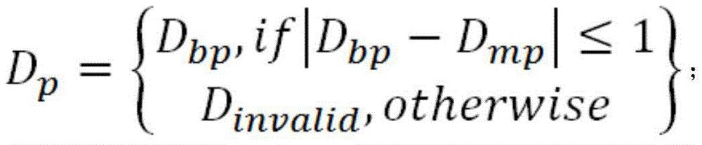
the method is characterized in that left and right images are exchanged in position, namely the left image is changed into a right image, the right image is changed into a left image, stereo matching is performed again to obtain another Zhang Shicha image, because each value in the disparity map reflects the corresponding relation between two pixels, according to the disparity constraint of disparity, the same-name-point pixel of each pixel in the right image and the disparity value corresponding to the pixel are found through the disparity map of the left image, if the absolute value of the difference between the two disparity values is less than 1, the uniqueness constraint is satisfied and is retained, otherwise, the uniqueness constraint is not satisfied and is removed, meanwhile, a connected domain detection method is adopted to remove isolated abnormal points, small blocks caused by error matching in the disparity map are removed, small isolated speckles are filtered, and the formula of the consistency check is as follows:
improving the parallax precision, obtaining the sub-pixel precision by adopting a sub-pixel optimization technology and a quadratic curve interpolation method, and performing quadratic curve fitting on the cost value of the optimal parallax and the cost values of the front parallax and the rear parallax, wherein the parallax value corresponding to the extreme point of the curve is a new sub-pixel parallax value; the parallax error optimization can be realized through the steps, and finally the parallax error image of the binocular camera after the stereo correction is obtained;
step 4.5: the disparity map of the binocular camera after stereo correction is used as input, depth calculation can be carried out, and a pixel depth calculation formula is as follows:
where f is the focal length, b is the baseline length, d is the parallax, c xr And c xl The column coordinates of the two camera principal points are subjected to depth calculation to obtain a depth map of a binocular camera left camera image subjected to stereo correction, and a spatial three-dimensional coordinate mapped to an actual three-dimensional space by the identified pipeline defect in the binocular camera left camera image subjected to stereo correction can be finally obtained by combining pipeline defect detection information obtained by deep learning target detection.
Compared with the prior art, the invention has the following beneficial effects:
(1) The pipeline defect detecting, positioning and ranging system based on binocular stereo vision realizes three-dimensional reconstruction of images captured by a binocular camera and positioning and ranging of detected targets through the binocular stereo vision technology, realizes target detection of pipeline defects by combining a deep learning technology, and has the characteristics of full automation, non-contact measurement, positioning accuracy, high real-time performance and the like.
(2) The binocular stereo vision-based pipeline defect detecting, positioning and ranging system can realize non-contact measurement of pipeline defects, and has the characteristics of wide monitoring range, good real-time performance, high accuracy and accurate positioning.
(3) The invention relates to a binocular stereo vision-based pipeline defect detection and positioning ranging system, which trains a deep learning network based on a target detection algorithm through a deep learning target detection module, realizes detection and identification of pipeline defects and obtains object identification information.
(4) According to the binocular stereo vision-based pipeline defect detecting, positioning and ranging system, the three-dimensional space coordinates of the pipeline defects are obtained through the stereo matching and depth calculating module, and accurate positioning and ranging of the pipeline defects are achieved.
Drawings
In order to more clearly illustrate the technical solutions of the embodiments of the present invention, the drawings that are required to be used in the embodiments will be briefly described below, it should be understood that the following drawings only illustrate some embodiments of the present invention and therefore should not be considered as limiting the scope, and that those skilled in the art can also obtain other related drawings based on the drawings without inventive efforts.
Fig. 1 is an overall framework diagram of the present invention.
Fig. 2 is a flow chart of the operation of the present invention.
FIG. 3 is a deep learning object detection module workflow diagram of the present invention.
FIG. 4 is a flowchart of the stereo matching and depth calculation module of the present invention.
Detailed Description
In order to make the objects, technical solutions and advantages of the embodiments of the present invention more apparent, the technical solutions of the embodiments of the present invention will be described in detail and completely with reference to the accompanying drawings. It is to be understood that the described embodiments are only a few embodiments of the present invention, and not all embodiments. All other embodiments, which can be obtained by a person skilled in the art without any inventive step based on the embodiments of the present invention, are within the scope of the present invention.
Thus, the following detailed description of the embodiments of the present invention, as presented in the figures, is not intended to limit the scope of the invention, as claimed, but is merely representative of selected embodiments of the invention. All other embodiments, which can be obtained by a person skilled in the art without any inventive step based on the embodiments of the present invention, are within the scope of the present invention.
The first embodiment is as follows:
as shown in fig. 1, a binocular stereo vision-based pipeline defect detection and positioning ranging system comprises a binocular camera image capturing module, a camera calibration module, a stereo correction module, a deep learning target detection module, and a stereo matching and depth calculation module;
the binocular camera image capturing module is used for capturing and collecting image data of the left camera and the right camera, realizing real-time capturing of a pipeline image, collecting pipeline defect image data and providing a data source for a pipeline defect data set;
the camera calibration module is used for correcting the image captured by the binocular camera to obtain an image with relatively small distortion, inputting the image coordinate and world coordinate of the known characteristic point of the calibration plate, establishing a geometric model of camera imaging, determining the relation between the pixel coordinate of the camera image and the three-dimensional coordinate of the scene point, and outputting the relation as the internal and external parameters and the distortion coefficient of the camera;
the stereo correction module adopts a visual system with an intersected optical axis structure, changes the relative positions of two cameras by decomposing a rotation matrix and a row alignment correction rotation matrix to enable corresponding points in two images to be on the same horizontal polar line, acquires corrected camera parameters by using a mathematical physics method on the basis of original data of the cameras, changes two-dimensional search into one-dimensional search, reduces a matching search space, improves the search rate of stereo matching, and finally finishes image correction through a correction mapping lookup table, cuts and stores the images;
a deep learning target detection module, which self-establishes a pipe defect data set through the pipe defect data collected by the binocular camera image capture module, trains a deep learning network based on a target detection algorithm, and the network deduces and predicts the image, inputting an RGB three-channel image captured by a left camera after stereo correction, and outputting a defect semantic label class, a recognition frame center coordinate (x, y) and a width and height (w, h) recognized in a left camera image, wherein the semantic label, the recognition frame center coordinate and the width and height data are used as object recognition information;
the stereoscopic matching and depth calculating module takes the stereoscopic corrected left and right camera images of the binocular camera and the pipeline defect detection information obtained through the deep learning object identification as input, obtains a parallax image of the stereoscopic corrected left camera of the binocular camera after the stereoscopic matching algorithm is processed, converts the parallax image into a depth image through depth calculation, and finally outputs the three-dimensional space coordinates mapped to the actual three-dimensional space by the identified object in the stereoscopic corrected left camera image of the binocular camera in combination with the pipeline defect detection information.
Capturing and collecting image data of a left camera and a right camera through a binocular camera image capturing module; establishing a camera imaging geometric model and correcting lens distortion through a camera calibration module to obtain internal and external parameters and a distortion coefficient of a camera; the coplanar line alignment of the left image and the right image is realized through a stereo correction module, so that the planes of the left image and the right image are parallel to a base line, and corresponding points in the left image and the right image are on the same horizontal polar line; training a deep learning network based on a target detection algorithm through a deep learning target detection module to realize detection and identification of the defects of the pipeline and obtain object identification information; and obtaining the spatial three-dimensional coordinates of the pipeline defects through the three-dimensional matching and depth calculating module, and realizing accurate positioning and ranging of the pipeline defects.
Referring to fig. 2, the binocular camera image capturing module, the camera calibration module, the stereo correction module, the deep learning target detection module, and the stereo matching and depth calculation module are connected through the following steps, the target detection and positioning ranging of the pipeline defects are realized:
the method comprises the following steps: calibrating a binocular camera, establishing a camera imaging geometric model, determining the mutual relation between the three-dimensional geometric position of a certain point on the surface of a space object and the corresponding point in an image, solving the internal reference, the external reference and the distortion coefficient of left and right cameras of the binocular camera by using the image coordinates and the world coordinates of the known characteristic points of a calibration plate, taking the internal reference, the external reference and the distortion coefficient of the left and right cameras of the binocular camera as camera calibration parameters, and correcting the image shot by the binocular camera by adjusting the internal reference, the external reference and the distortion coefficient to obtain an image with relatively small distortion;
the first step is realized by the following steps:
step 1.1: making a chessboard calibration plate consisting of black and white square intervals, shooting and sampling the chessboard grid calibration plate for multiple times by using a binocular camera at multiple positions, multiple angles and multiple postures, so that the single-plane chessboard grid is clearly imaged in left and right cameras, and extracting angular point information of each calibration picture to obtain image coordinates of all inner angular points on the calibration picture and space three-dimensional coordinates of all inner angular points on the calibration plate image;
step 1.2: establishing a camera imaging geometric model, and determining the correlation between the three-dimensional geometric position of a certain point on the surface of a space object and the corresponding point in the image, wherein the geometric model parameters are camera calibration parameters and comprise internal and external parameters and a distortion coefficient;
an external parameter matrix W reflecting the conversion between a camera coordinate system and a world coordinate system, wherein R is a rotation matrix of a right camera relative to a left camera of the binocular camera, t is a translation vector of the right camera relative to the left camera of the binocular camera, an internal parameter matrix M reflecting the conversion between a pixel coordinate system and the camera coordinate system, wherein f is a lens focal length, (u) is a coordinate system of a camera, and 0 ,v 0 ) As the coordinates of the origin of the image coordinate system in the pixel coordinate system, d x 、d y And (3) for the size of each pixel point in the directions of the x axis and the y axis of the image coordinate system:
step 1.3: taking the image coordinates of all inner corner points on the calibration image obtained in the step 1.1 and the spatial three-dimensional coordinates of all inner corner points on the calibration plate image as input, solving and outputting the internal reference, external reference and distortion coefficients of the left camera and the right camera of the binocular camera through experiments and calculation according to a geometric model of camera imaging;
step 1.4: calibrating internal and external parameters of the binocular camera in the step 1.3 to be used as known constants, and solving 5 distortion parameters k by using coordinate relations before and after correction according to coordinate information obtained in the step 1.1 1 、k 2 、k 3 、p 1 、p 2 And (3) carrying out distortion correction:
wherein (x) p ,y p ) Is the original coordinates of the image, (x) tcorr ,y tcorr ) After image correctionCoordinates, approximately described by a taylor series expansion at r = 0.
Step two: performing stereo correction through epipolar constraint to enable corresponding points in the two images to be on the same horizontal epipolar line, acquiring corrected camera parameters, calling OpenCV to acquire parameters of left and right corrected cameras in real time to finish correction, and finally acquiring corrected images through correction mapping;
the second step is realized by the following steps:
step 2.1: dividing binocular camera rotation matrix R into synthesis rotation matrix R of left camera and right camera 1 And r 2 The left camera and the right camera respectively rotate by half, so that the optical axes of the left camera and the right camera are parallel, and the imaging surfaces of the left camera and the right camera are coplanar;
step 2.2: inputting a composite rotation matrix r of left and right cameras 1 And r 2 Calling cvStereoRectify function in OpenCV and outputting left and right camera row alignment correction rotation matrix R according to original left and right camera internal parameter matrix, translation vector t and chessboard image size 1 And R 2 And the internal reference matrix M of the left camera and the right camera after correction l And M r And a projection matrix P of the left camera and the right camera after correction l And P r And a reprojection matrix Q;
step 2.3: and (3) taking the output matrix in the step 2.2 as a known constant, searching a mapping table through correction of left and right views, adopting reverse mapping to find out a floating point position on a corresponding source image of each shaped pixel position on a target image, interpolating each shaped value of surrounding source pixels, cutting the image after the corrected image is assigned, and storing a correction result.
Step three: acquiring a large number of pipeline defect images in advance through a binocular camera, building a pipeline defect data set, screening and enhancing the data set to optimize the data set, carrying out image annotation on the pipeline defect images based on the self-built data set, starting to train a deep convolutional neural network model after the annotation is completed, deducing the obtained weights after the training is completed, analyzing a detection result to obtain a weight file for detecting the pipeline defects, capturing the images in real time through a binocular camera image capturing module during actual use, and detecting pipeline defect targets based on the weight file to obtain pipeline defect detection information;
referring to fig. 3, the third step is implemented as follows:
step 3.1: acquiring data, namely acquiring a large number of images in advance through a binocular camera, shooting images containing pipeline defects, and building a pipeline defect data set by self;
step 3.2: screening and enhancing data, namely primarily screening the pipeline defect data set, removing invalid data, performing data enhancement operation on the primarily screened image, and optimizing the pipeline defect data set so as to improve the training effect;
step 3.3: image labeling, labeling possible targets, generating a labeled file, organizing a training directory, and constructing a training set, a verification set and a test set required by training;
step 3.4: image training, wherein model iteration is carried out on the basis of a pre-training model, training results are detected through jutter, and parameters are adjusted to prevent overfitting;
step 3.5: image inference, which is to infer the weight obtained after image training, analyze the detection result by using the actually shot picture, and if the detection effect is good, perform target detection by using the weight file obtained by training;
step 3.6: and target detection, namely aggregating and forming a convolutional neural network of image characteristics on different image fine granularities through images captured by a binocular camera in real time, mixing and combining the image characteristics, transmitting the image characteristics to a prediction layer, predicting the image characteristics, generating a boundary frame and predicting the type, and finally obtaining pipeline defect detection information.
The neural network of the YOLOv5 target detection algorithm disclosed by the invention specifically comprises the following steps:
1. data enhancement, namely, randomly pasting the reduced image to a COCO 2017 data set to increase the number of the data set, and simultaneously, further generalizing the enhanced data set in the modes of random scaling, random cutting and random arrangement;
2. focus interleaved stitching, scaling the image uniformly to the size of (3,640,640) as input, copying four copies, cutting the four pictures into four slices (3,320,320) by a slicing operation, connecting the four slices in depth by using Concat, outputting (12,20,320), generating an output (32,320,320) by a convolution layer with 32 convolution kernels, and finally inputting the result to the next convolution layer through batch _ borm and leave _ relu;
3. the method comprises the following steps that (1) Backbone, aggregating and forming a convolutional neural network of image features on different image fine granularities, wherein Bottleneck is a classical residual error structure, namely a 1 × 1 convolutional layer and a 3 × 3 convolutional layer, finally adding an initial input through the residual error structure, dividing the original input into two branches by CSP (chip size protocol), performing convolution operation to reduce the number of channels to half respectively, performing Bottleneck × N operation on the branch 1, and then performing Concat branch 1 and branch 2 to enable the input and the output of the Bottleneck CSP to be the same in size, so that a model can learn more features;
4. and (6) selecting the Neck: the network layer mixes and combines the image features and passes the image features to the prediction layer. The most important is the SPP structure, the input of the SPP is 512 multiplied by 20, 256 multiplied by 20 is output after 1 multiplied by 1 convolutional layer, then three parallel MaxPools are used for sampling, the result is added with the initial characteristic of the result to output 1024 multiplied by 20, and finally 512 convolutional kernels are used for restoring the result to 512 multiplied by 20;
5. head: and predicting the image characteristics, generating a boundary box and predicting the category.
For YOLOv5, the weight files of each class are consistent with backlight, rock and Head. The only difference is in the depth and width settings of the model, and the network structure of the model can be adjusted by only modifying the two parameters, wherein the parameter of yolov5l is the default parameter.
Step four: the method comprises the steps of taking left and right camera images of a binocular camera after stereo correction and pipeline defect detection information obtained through deep learning object recognition as input quantities, transmitting the input quantities to a stereo matching and depth calculation module, taking a central coordinate of a recognition frame in the pipeline defect detection information as a reference quantity, processing the images through the stereo matching and depth calculation module, outputting the processed images, and mapping recognized pipeline defects in the left camera image of the binocular camera after stereo correction to space three-dimensional coordinates in an actual three-dimensional space.
With reference to fig. 4, the fourth step is implemented as follows:
step 4.1: taking left and right camera images of a binocular camera after stereo correction as input, performing matching cost calculation in a preset parallax range, wherein the purpose of the matching cost calculation is to measure the correlation between a pixel to be matched and a candidate pixel, whether the two pixels are homonymy points or not, the matching cost can be calculated through a matching cost function, the lower the cost is, the larger the correlation is, the higher the probability of homonymy points is, and the calculation formula is as follows:
matching cost calculation of binocular camera left and right images subjected to stereo correction in a preset parallax range can be achieved through a formula, and the matching cost of each pixel point of an original image in the preset parallax range is obtained;
and 4.2: the method comprises the following steps of taking the matching cost of each pixel point calculated in a preset parallax range as input, carrying out cost aggregation, and simply finding the optimal parallax of each pixel to enable the global energy function of the whole image to be minimum by adopting the idea of a global stereo matching algorithm, namely a global energy optimization strategy, wherein the definition of the global energy function is as follows:
E(d)=E data (d)+E smooth (d);
adopting a path cost aggregation method, namely performing one-dimensional aggregation on matching costs under all parallaxes of pixels on all paths around the pixels to obtain path cost values under the paths, then adding all the path cost values to obtain the matched cost values after the pixels are aggregated, wherein the path cost calculation method of the pixels p along a certain path r is as follows:
wherein p represents a pixel, r represents a path, d represents parallax, p-r represents a pixel in the p path of the pixel, L represents a certain path aggregation cost value, lr (p-r, d) represents the cost value when the parallax of the last pixel in the path is d, lr (p-r, d-1) represents the cost value when the parallax of the last pixel in the path is d-1, lr (p-r, d + 1) represents the cost value when the parallax of the last pixel in the path is d +1, min i L r (p-r, i) represents the minimum of all cost values of the last pixel in the path;
the first item is a matching cost value C and belongs to a data item; the second item is a smooth item, the value accumulated on the path cost is taken, no punishment is made, and P is made 1 Punishment and do P 2 Punishing the value with the minimum cost in the three cases; p is 1 In order to adapt to inclined or curved surfaces, P 2 Then the purpose is to preserve the discontinuity. P 2 It is often dynamically adjusted according to the gray level difference of the adjacent pixels, as shown in the following formula:
P 2 is' P 2 Is generally set to be much larger than P 1 Number of (1), I bp And I bq Representing the gray values of pixels p and q, respectively; the third term is to ensure that the new path cost value Lr does not exceed a certain numerical upper limit,
the total path cost value S can be calculated by the following formula:
the cost aggregation of multiple paths can be realized through various calculations, and a multi-path cost aggregation value of each pixel in a preset parallax range is obtained;
step 4.3: performing parallax calculation by taking a multipath cost aggregation value of each pixel in a preset parallax range as input, wherein the parallax calculation is to determine an optimal parallax value of each pixel through a cost matrix S after cost aggregation, and a Winner-take-all algorithm is adopted, namely, in the cost values of all parallaxes of a certain pixel, a parallax corresponding to the minimum cost value is selected as the optimal parallax, and finally, the parallax of each pixel after cost aggregation is obtained;
step 4.4: performing parallax optimization by taking the parallax of each pixel after cost aggregation as input, wherein the purpose of parallax optimization is to further optimize the parallax image obtained in the last step, improve the quality of the parallax image, and comprise rejecting error matching, improving parallax precision and inhibiting noise;
the method is characterized in that left and right images are exchanged in position, namely the left image is changed into the right image, the right image is changed into the left image, stereo matching is performed again to obtain another Zhang Shicha image, each value in the disparity map reflects the corresponding relation between two pixels, according to the disparity map of the left image, a homonym point pixel of each pixel in the right image and a disparity value corresponding to the pixel are found through the disparity map of the left image, if the absolute value of the difference between the two disparity values is less than 1, the uniqueness constraint is satisfied and retained, otherwise, the uniqueness constraint is not satisfied and the disparity is eliminated, meanwhile, a connected domain detection method is adopted to eliminate the isolated abnormal constant points, small clusters caused by the error matching in the disparity map are removed, and small isolated speckles are filtered, and the formula for the consistency check is as follows:
improving the parallax precision, obtaining the sub-pixel precision by adopting a sub-pixel optimization technology and a quadratic curve interpolation method, and performing quadratic curve fitting on the cost value of the optimal parallax and the cost values of the front parallax and the rear parallax, wherein the parallax value corresponding to the extreme point of the curve is a new sub-pixel parallax value; the median filtering is adopted for noise suppression, so that the parallax result is smoother, the noise in the parallax image is eliminated to a certain extent, and the parallax filling effect is achieved;
step 4.5: the disparity map of the binocular camera after stereo correction is used as input, depth calculation can be carried out, and a pixel depth calculation formula is as follows:
where f is the focal length, b is the baseline length, d is the parallax, c xr And c xl The column coordinates of the two camera principal points are subjected to depth calculation to obtain a depth map of a binocular camera left camera image subjected to stereo correction, and a spatial three-dimensional coordinate mapped to an actual three-dimensional space by the identified pipeline defect in the binocular camera left camera image subjected to stereo correction can be finally obtained by combining pipeline defect detection information obtained by deep learning target detection.
Through the steps, the space three-dimensional coordinates of the pipeline defects are obtained, namely, the target detection and the positioning ranging of the pipeline defects are realized, the three-dimensional reconstruction of images captured by a binocular camera and the positioning ranging of the detected targets are realized through a binocular stereo vision technology, the target detection of the pipeline defects is realized by combining a deep learning technology, and the method has the characteristics of full automation, non-contact measurement, positioning accuracy, high real-time performance and the like.
The device obtained by the technical scheme is a binocular stereo vision-based pipeline defect detection and positioning ranging system, and the binocular camera image capturing module, the camera calibration module, the stereo correction module, the deep learning target detection module and the stereo matching and depth calculation module are arranged, so that the working process is as follows: the target detection and positioning ranging of the pipeline defects can be realized by the first step, the second step, the third step and the fourth step.
The above description is only a preferred embodiment of the present invention, and is not intended to limit the present invention, and it will be apparent to those skilled in the art that various modifications and variations can be made in the present invention; any modification, equivalent replacement, or improvement made within the spirit and principle of the present invention should be included in the protection scope of the present invention.