JP7344228B2 - Aerosol-generating articles and apparatus for forming aerosol-generating articles - Google Patents
Aerosol-generating articles and apparatus for forming aerosol-generating articles Download PDFInfo
- Publication number
- JP7344228B2 JP7344228B2 JP2020568762A JP2020568762A JP7344228B2 JP 7344228 B2 JP7344228 B2 JP 7344228B2 JP 2020568762 A JP2020568762 A JP 2020568762A JP 2020568762 A JP2020568762 A JP 2020568762A JP 7344228 B2 JP7344228 B2 JP 7344228B2
- Authority
- JP
- Japan
- Prior art keywords
- aerosol
- wrapper
- forming substrate
- substantially non
- flammable
- Prior art date
- Legal status (The legal status is an assumption and is not a legal conclusion. Google has not performed a legal analysis and makes no representation as to the accuracy of the status listed.)
- Active
Links
Images


Classifications
-
- A—HUMAN NECESSITIES
- A24—TOBACCO; CIGARS; CIGARETTES; SIMULATED SMOKING DEVICES; SMOKERS' REQUISITES
- A24C—MACHINES FOR MAKING CIGARS OR CIGARETTES
- A24C5/00—Making cigarettes; Making tipping materials for, or attaching filters or mouthpieces to, cigars or cigarettes
- A24C5/005—Treatment of cigarette paper
-
- A—HUMAN NECESSITIES
- A24—TOBACCO; CIGARS; CIGARETTES; SIMULATED SMOKING DEVICES; SMOKERS' REQUISITES
- A24D—CIGARS; CIGARETTES; TOBACCO SMOKE FILTERS; MOUTHPIECES OF CIGARS OR CIGARETTES; MANUFACTURE OF TOBACCO SMOKE FILTERS OR MOUTHPIECES
- A24D1/00—Cigars; Cigarettes
- A24D1/02—Cigars; Cigarettes with special covers
- A24D1/025—Cigars; Cigarettes with special covers the covers having material applied to defined areas, e.g. bands for reducing the ignition propensity
-
- A—HUMAN NECESSITIES
- A24—TOBACCO; CIGARS; CIGARETTES; SIMULATED SMOKING DEVICES; SMOKERS' REQUISITES
- A24D—CIGARS; CIGARETTES; TOBACCO SMOKE FILTERS; MOUTHPIECES OF CIGARS OR CIGARETTES; MANUFACTURE OF TOBACCO SMOKE FILTERS OR MOUTHPIECES
- A24D1/00—Cigars; Cigarettes
- A24D1/20—Cigarettes specially adapted for simulated smoking devices
-
- D—TEXTILES; PAPER
- D21—PAPER-MAKING; PRODUCTION OF CELLULOSE
- D21H—PULP COMPOSITIONS; PREPARATION THEREOF NOT COVERED BY SUBCLASSES D21C OR D21D; IMPREGNATING OR COATING OF PAPER; TREATMENT OF FINISHED PAPER NOT COVERED BY CLASS B31 OR SUBCLASS D21G; PAPER NOT OTHERWISE PROVIDED FOR
- D21H27/00—Special paper not otherwise provided for, e.g. made by multi-step processes
- D21H27/30—Multi-ply
-
- D—TEXTILES; PAPER
- D21—PAPER-MAKING; PRODUCTION OF CELLULOSE
- D21H—PULP COMPOSITIONS; PREPARATION THEREOF NOT COVERED BY SUBCLASSES D21C OR D21D; IMPREGNATING OR COATING OF PAPER; TREATMENT OF FINISHED PAPER NOT COVERED BY CLASS B31 OR SUBCLASS D21G; PAPER NOT OTHERWISE PROVIDED FOR
- D21H5/00—Special paper or cardboard not otherwise provided for
- D21H5/02—Patterned paper
- D21H5/06—Apparatus
-
- D—TEXTILES; PAPER
- D21—PAPER-MAKING; PRODUCTION OF CELLULOSE
- D21H—PULP COMPOSITIONS; PREPARATION THEREOF NOT COVERED BY SUBCLASSES D21C OR D21D; IMPREGNATING OR COATING OF PAPER; TREATMENT OF FINISHED PAPER NOT COVERED BY CLASS B31 OR SUBCLASS D21G; PAPER NOT OTHERWISE PROVIDED FOR
- D21H5/00—Special paper or cardboard not otherwise provided for
- D21H5/12—Special paper or cardboard not otherwise provided for characterised by the use of special fibrous materials
- D21H5/14—Special paper or cardboard not otherwise provided for characterised by the use of special fibrous materials of cellulose fibres only
- D21H5/16—Tobacco or cigarette paper
Landscapes
- Cigarettes, Filters, And Manufacturing Of Filters (AREA)
- Manufacturing Of Cigar And Cigarette Tobacco (AREA)
- Resistance Heating (AREA)
- Nozzles (AREA)
- Containers And Packaging Bodies Having A Special Means To Remove Contents (AREA)
- Catching Or Destruction (AREA)
Description
本発明は、エアロゾル発生装置の発熱体または一体型の発熱体によって加熱された時に吸入可能なエアロゾルを発生するためのエアロゾル形成基体を備えるエアロゾル発生物品に関する。本発明はまた、こうしたエアロゾル発生物品を製造するための装置、およびこうしたエアロゾル発生物品を製造するための方法にも関する。 The present invention relates to an aerosol-generating article comprising an aerosol-forming substrate for generating an inhalable aerosol when heated by a heating element of an aerosol-generating device or an integrated heating element. The invention also relates to apparatus for making such aerosol-generating articles and methods for making such aerosol-generating articles.
たばこが燃焼するよりはむしろ加熱される多くの喫煙物品が、当技術分野において提唱されてきた。こうした加熱式喫煙物品の一つの目的は、従来の紙巻たばこにおけるたばこの燃焼および熱分解性分解によって生成されるタイプの周知の有害な煙成分を減少させることである。 Many smoking articles have been proposed in the art in which the tobacco is heated rather than burned. One purpose of such heated smoking articles is to reduce known harmful smoke components of the type produced by tobacco combustion and pyrolytic decomposition in conventional cigarettes.
典型的に、こうした加熱式喫煙物品においてエアロゾルは、熱源の中、熱源の周囲、または熱源の下流に位置していてもよい物理的に分離されたエアロゾル形成基体または材料に、熱源からの熱を伝達することによって生成される。喫煙中、揮発性化合物は、熱源からの熱伝達によってエアロゾル形成基体から放出され、喫煙物品を通して引き出された空気中に混入される。放出された化合物が冷えるにつれて、これらは凝縮してユーザーによって吸入されるエアロゾルを形成する。 Typically, in such heated smoking articles, the aerosol transfers heat from the heat source to a physically separated aerosol-forming substrate or material that may be located in, around, or downstream from the heat source. Generated by communicating. During smoking, volatile compounds are released from the aerosol-forming substrate by heat transfer from the heat source and become entrained in the air drawn through the smoking article. As the released compounds cool, they condense to form an aerosol that is inhaled by the user.
多くの先行技術の文書で、加熱式喫煙物品を消費または喫煙するためのエアロゾル発生装置が開示されている。こうした装置には、例えばエアロゾル発生装置の一つ以上の電気発熱体から加熱式喫煙物品のエアロゾル形成基体への熱伝達によってエアロゾルが生成される電気加熱式エアロゾル発生装置が含まれる。こうした電気式喫煙システムの一つの利点は、副流煙を著しく低減しつつ、使用者が喫煙を選択的に一時停止および再開できるようにすることである。 Many prior art documents disclose aerosol generating devices for consuming or smoking heated smoking articles. Such devices include, for example, electrically heated aerosol generators in which an aerosol is produced by heat transfer from one or more electrical heating elements of the aerosol generator to an aerosol-forming substrate of a heated smoking article. One advantage of such electric smoking systems is that they allow users to selectively pause and resume smoking while significantly reducing sidestream smoke.
電気式喫煙システムで使用される電気加熱式紙巻たばこの例は、US2005/0172976A1号に開示されている。電気加熱式紙巻たばこは、電気式喫煙システムの再使用可能なライターの紙巻たばこレシーバの中に挿入されるように構築される。ライターは、発熱体が紙巻たばこに沿って位置付けられるように、紙巻きたばこをスライドできる形で受けるように配置されている、複数の電気抵抗性のある発熱体を含むヒーター取付具にエネルギーを供給する電源を含む。US2005/0172976A1号に開示されている電気式喫煙システムで使用される電気加熱式紙巻たばこは、パルス加熱を使用して電気加熱式紙巻たばこにエネルギーを提供しうる。 An example of an electrically heated cigarette for use in an electrical smoking system is disclosed in US 2005/0172976A1. Electrically heated cigarettes are constructed to be inserted into a cigarette receiver of a reusable lighter of an electric smoking system. The lighter supplies energy to a heater fixture that includes a plurality of electrically resistive heating elements that are arranged to slidably receive the cigarette such that the heating elements are positioned along the cigarette. Includes power supply. The electrically heated cigarette used in the electrical smoking system disclosed in US 2005/0172976A1 may use pulsed heating to provide energy to the electrically heated cigarette.
上述の通り、US2005/0172976A1号に開示されている電気加熱式紙巻たばこは、複数の外部発熱体を備える電気式喫煙システムで使用するためのものである。内部発熱体を有するエアロゾル発生装置を備えた電気式喫煙システムも公知である。使用時に、内部発熱体がエアロゾル形成基体と直接接触するように、こうした電気式喫煙システムのエアロゾル発生装置の内部発熱体が加熱式喫煙物品のエアロゾル形成基体の中に挿入される。 As mentioned above, the electrically heated cigarette disclosed in US 2005/0172976A1 is for use in an electrical smoking system comprising multiple external heating elements. Electric smoking systems with aerosol generators having internal heating elements are also known. In use, the internal heating element of the aerosol generator of such electric smoking systems is inserted into the aerosol-forming substrate of the heated smoking article such that the internal heating element is in direct contact with the aerosol-forming substrate.
エアロゾル発生装置の内部発熱体と加熱式喫煙物品のエアロゾル形成基体との間の直接接触が、エアロゾル形成基体を加熱して、吸入可能なエアロゾルを形成するための効率的な手段を提供することができる。こうした構成では、内部発熱体からの熱は、内部発熱体が作動した時にエアロゾル形成基体の少なくとも一部にほぼ瞬間的に伝達されることができ、またこれによってエアロゾルの急速な発生が促進されうる。さらに、エアロゾルを発生させるために必要とされる全体的な加熱エネルギーは、エアロゾル形成基体が外部発熱体と直接接触せず、かつエアロゾル形成基体の初期加熱が対流または放射によって起こる、外部ヒーター要素を備える喫煙システムにおける場合よりも低くなりうる。エアロゾル発生装置の内部発熱体がエアロゾル形成基体と直接接触している場合、内部発熱体と直接接触しているエアロゾル形成基体の部分の初期加熱は伝導によって達成される。 Direct contact between the internal heating element of the aerosol generator and the aerosol-forming substrate of the heated smoking article may provide an efficient means for heating the aerosol-forming substrate to form an inhalable aerosol. can. In such a configuration, heat from the internal heating element can be almost instantaneously transferred to at least a portion of the aerosol-forming substrate when the internal heating element is activated, and this can facilitate rapid generation of aerosol. . Furthermore, the overall heating energy required to generate an aerosol is reduced by using an external heating element, where the aerosol-forming substrate is not in direct contact with an external heating element, and where the initial heating of the aerosol-forming substrate occurs by convection or radiation. may be lower than in equipped smoking systems. When the internal heating element of the aerosol generator is in direct contact with the aerosol-forming substrate, the initial heating of the portion of the aerosol-forming substrate that is in direct contact with the internal heating element is accomplished by conduction.
代替的な加熱式喫煙物品では、エアロゾルは、加熱式喫煙物品の一部を形成し、エアロゾル形成基体または材料に隣接した熱源からの熱伝達によって発生される。熱源は、エアロゾル形成基体または材料の中、その周り、または最も典型的にはその上流に位置していてもよい。 In alternative heated smoking articles, the aerosol is generated by heat transfer from a heat source that forms part of the heated smoking article and is adjacent to the aerosol-forming substrate or material. The heat source may be located in, around, or most typically upstream of the aerosol-forming substrate or material.
加熱式喫煙物品の熱源がエアロゾル形成基体と直接接触している場合、熱源と直接接触しているエアロゾル形成基体の部分の初期加熱は伝導によって達成される。 When the heat source of the heated smoking article is in direct contact with the aerosol-forming substrate, the initial heating of the portion of the aerosol-forming substrate that is in direct contact with the heat source is accomplished by conduction.
本発明は、先行技術のエアロゾル発生物品の少なくとも代替を提供する。特に、本発明は、内部または外部発熱体によって加熱された時に吸入可能なエアロゾルを発生させるためのエアロゾル形成基体を備えるエアロゾル発生物品に関する。本発明はまた、こうしたエアロゾル発生物品を製造するための装置および方法に関する。 The present invention provides at least an alternative to prior art aerosol generating articles. In particular, the present invention relates to an aerosol-generating article comprising an aerosol-forming substrate for generating an inhalable aerosol when heated by an internal or external heating element. The present invention also relates to apparatus and methods for manufacturing such aerosol-generating articles.
本発明の態様は、添付の特許請求の範囲による、発熱体を備えるエアロゾル発生装置で使用するためのエアロゾル発生物品、発熱体を備えるエアロゾル発生物品、およびエアロゾル形成基体を囲むためのエンボス加工されたラッパーを形成するための装置および方法を提供する。 Aspects of the present invention provide an aerosol-generating article for use in an aerosol-generating device comprising a heating element, an aerosol-generating article comprising a heating element, and an embossed article for surrounding an aerosol-forming substrate, according to the appended claims. Apparatus and methods for forming wrappers are provided.
本発明の態様によると、発熱体を備えるエアロゾル発生装置で使用するためのエアロゾル発生物品が提供されており、エアロゾル発生物品は、エアロゾル形成基体と、エアロゾル形成基体を囲み、内表面および外表面を含む、実質的に不燃性のラッパーとを備え、ラッパーの内表面は、ラッパーがエアロゾル形成基体の周りに巻かれた時に、ラッパーの外表面の一部分と重なるように構成された少なくとも部分的にテクスチャ加工を施した表面を有する。このようにして、テクスチャ加工を施した表面は、ラッパーの外表面に接着されうる。理論に束縛されることを望むものではないが、テクスチャ加工を施した表面は、接着剤を塗布することができる表面積を増大させ、それによってラッパーの内表面と外表面との間の接着力を増大させる。それ故に、テクスチャ加工を施した表面が接着剤によって外表面に接着される場合、ラッパーの内表面と外表面の分離が回避される。 According to an aspect of the invention, an aerosol-generating article for use in an aerosol-generating device that includes a heating element is provided, the aerosol-generating article including an aerosol-forming substrate, surrounding the aerosol-forming substrate, and having an inner surface and an outer surface. a substantially non-flammable wrapper, the inner surface of the wrapper being at least partially textured and configured to overlap a portion of the outer surface of the wrapper when the wrapper is wrapped around the aerosol-forming substrate. It has a processed surface. In this way, the textured surface can be adhered to the outer surface of the wrapper. Without wishing to be bound by theory, it is believed that the textured surface increases the surface area to which adhesive can be applied, thereby increasing the adhesive force between the inner and outer surfaces of the wrapper. increase Separation of the inner and outer surfaces of the wrapper is therefore avoided when the textured surface is adhered to the outer surface by means of an adhesive.
本発明のさらなる態様によると、たばこおよびニコチン供与源のうちの一つ以上を含むエアロゾル形成基体と、エアロゾル形成基体の上流端にあり、作動した時にエアロゾルを形成するようにエアロゾル形成基体を加熱するように配置される、発熱体と、エアロゾル形成基体および発熱体の少なくとも一部分を囲む実質的に不燃性のラッパーであって、内表面および外表面を含む、実質的に不燃性のラッパーとを備え、ラッパーの内表面が、ラッパーがエアロゾル形成基体の周りに巻かれた時に、ラッパーの外表面の一部分に重なるように構成された少なくとも部分的にテクスチャ加工を施した表面を有する、エアロゾル発生物品が提供されている。それ故に、テクスチャ加工を施した表面が接着剤によって外表面に接着される場合、ラッパーの内表面と外表面の分離が回避される。 According to a further aspect of the invention, an aerosol-forming substrate comprising one or more of a tobacco and a nicotine source, the aerosol-forming substrate being at an upstream end of the aerosol-forming substrate and heating the aerosol-forming substrate to form an aerosol when actuated; a heating element and a substantially non-flammable wrapper surrounding at least a portion of the aerosol-forming substrate and the heating element, the substantially non-flammable wrapper including an inner surface and an outer surface, the substantially non-flammable wrapper being arranged to an aerosol-generating article, wherein the inner surface of the wrapper has an at least partially textured surface configured to overlap a portion of the outer surface of the wrapper when the wrapper is wrapped around an aerosol-forming substrate; provided. Separation of the inner and outer surfaces of the wrapper is therefore avoided when the textured surface is adhered to the outer surface by means of an adhesive.
本明細書で使用される場合、「実質的に不燃性のラッパー」とは、熱伝導性の不燃性層を含むラッパーを記述するために使用される。 As used herein, "substantially non-flammable wrapper" is used to describe a wrapper that includes a thermally conductive non-flammable layer.
ある特定の実施形態において、少なくとも部分的にテクスチャ加工を施した表面はエンボス加工される。より具体的には、エンボス加工された表面は、実質的に不燃性のラッパーの材料の隆起部分および陥没部分のパターンを含む。 In certain embodiments, the at least partially textured surface is embossed. More specifically, the embossed surface includes a pattern of raised and recessed portions of substantially non-combustible wrapper material.
ある特定の実施形態において、実質的に不燃性のラッパーの材料の隆起部分および陥没部分のパターンは、規則的なパターンである。 In certain embodiments, the pattern of raised and depressed portions of the substantially non-flammable wrapper material is a regular pattern.
本明細書で使用される場合、「規則的なパターン」という用語は、実質的に不燃性のラッパーの材料の隆起部分および陥没部分の規則的な配列を含むパターンを記述するために使用される。 As used herein, the term "regular pattern" is used to describe a pattern that includes a regular array of raised and depressed portions of substantially non-combustible wrapper material. .
ある特定の実施形態において、実質的に不燃性のラッパーの材料の隆起部分および陥没部分のパターンは、不規則なパターンである。 In certain embodiments, the pattern of raised and recessed portions of the material of the substantially non-combustible wrapper is an irregular pattern.
本明細書で使用される場合、「不規則なパターン」という用語は、実質的に不燃性のラッパーの材料の隆起部分および陥没部分の非繰り返しまたはランダムな配列を含むパターンを記述するために使用される。 As used herein, the term "irregular pattern" is used to describe a pattern that includes a non-repetitive or random arrangement of raised and recessed portions of substantially non-combustible wrapper material. be done.
ある特定の実施形態において、テクスチャ加工を施した表面は、ラッパーを変形させることによって形成される。例えば、テクスチャ加工を施した表面は、ラッパーをエンボス加工、スタンピング、またはプレスすることによって形成されうる。 In certain embodiments, the textured surface is formed by deforming the wrapper. For example, a textured surface can be formed by embossing, stamping, or pressing the wrapper.
ある特定の実施形態において、実質的に不燃性のラッパーは滑らかな外表面を有する。すなわち、内表面のテクスチャは、ラッパーの部分的な厚さを通して延びる。このようにして、ユーザーに見える外側ラッパーの視覚的完全性は無傷のままである。内表面のテクスチャ加工を施した表面は、製品の全体的な外観には影響を与えない。 In certain embodiments, the substantially non-flammable wrapper has a smooth outer surface. That is, the inner surface texture extends through the partial thickness of the wrapper. In this way, the visual integrity of the outer wrapper visible to the user remains intact. The textured inner surface does not affect the overall appearance of the product.
ある特定の実施形態において、テクスチャ加工を施した表面を有する実質的に不燃性のラッパーの部分は、エアロゾル形成基体の外周の周りに少なくとも部分的に延びる。より具体的には、実質的に不燃性のラッパーの内表面は、テクスチャ加工を施した部分と滑らかな部分とを含む。さらにより具体的には、実質的に不燃性のラッパーは、テクスチャ加工を施した部分の長軸方向のストライプと、滑らかな部分の長軸方向のストライプとを含む。 In certain embodiments, a portion of the substantially non-flammable wrapper having a textured surface extends at least partially around the perimeter of the aerosol-forming substrate. More specifically, the inner surface of the substantially non-flammable wrapper includes a textured portion and a smooth portion. Even more specifically, the substantially non-flammable wrapper includes longitudinal stripes of textured portions and longitudinal stripes of smooth portions.
ある特定の実施形態において、テクスチャ加工を施した部分は、実質的に不燃性のラッパーの端に沿って延びる。より具体的には、テクスチャ加工を施した部分は、実質的に不燃性のラッパーの長軸方向の端に沿って延びる。このようにして、テクスチャ加工を施した部分は、ラッパーがエアロゾル形成基体を囲む時にラッパーの対向する端の外表面と重なる、ラッパーの内表面の部分を形成する。それ故に、内側ラッパー上のテクスチャは、エアロゾル形成基体と接触するラッパーの部分には影響を与えない。より具体的には、実質的に不燃性のラッパーの内表面の滑らかな部分は、エアロゾル形成基体と接触し、実質的に不燃性のラッパーの内表面のテクスチャ加工を施した部分は、ラッパーがエアロゾル形成基体を囲む時に実質的に不燃性のラッパーの外表面の一部分と共にラッパーの継ぎ目を形成する。このようにして、ラッパーの継ぎ目の接着強度が、エアロゾル形成基体との境界面のラッパー表面を変えることなく改善される。 In certain embodiments, the textured portion extends along an edge of the substantially non-combustible wrapper. More specifically, the textured portion extends along a longitudinal edge of the substantially non-combustible wrapper. In this way, the textured portion forms a portion of the inner surface of the wrapper that overlaps the outer surface of the opposite end of the wrapper when the wrapper surrounds the aerosol-forming substrate. Therefore, the texture on the inner wrapper does not affect the portion of the wrapper that comes into contact with the aerosol-forming substrate. More specifically, the smooth portion of the inner surface of the substantially non-flammable wrapper contacts the aerosol-forming substrate, and the textured portion of the inner surface of the substantially non-flammable wrapper contacts the aerosol-forming substrate, and the textured portion of the inner surface of the substantially non-flammable wrapper allows A wrapper seam is formed with a portion of the wrapper's outer surface that is substantially non-flammable when surrounding the aerosol-forming substrate. In this way, the adhesive strength of the wrapper seam is improved without changing the wrapper surface at the interface with the aerosol-forming substrate.
ある特定の実施形態において、テクスチャ加工を施した部分は、約10ミリメートル~約20ミリメートルの幅である。より具体的には、テクスチャ加工を施した部分は15ミリメートルの幅であってもよい。部分の幅は、実質的に不燃性のラッパーの横断方向(短)寸法にわたって測定される。このようにして、テクスチャ加工を施した部分は、エアロゾル形成基体の周りに巻かれた時に、ラッパーの端間の重なりに提供される。それ故に、テクスチャ加工を施した部分は、ラッパーの内表面と外表面との間の継ぎ目の一つの表面を形成する。 In certain embodiments, the textured portion is about 10 millimeters to about 20 millimeters wide. More specifically, the textured portion may be 15 millimeters wide. The width of the section is measured across the transverse (minor) dimension of the substantially non-combustible wrapper. In this way, the textured portion is provided in the overlap between the ends of the wrapper when wrapped around the aerosol-forming substrate. The textured portion therefore forms one surface of the seam between the inner and outer surfaces of the wrapper.
ある特定の実施形態において、テクスチャ加工を施した部分は、ラッパーがエアロゾル形成基体を囲む時にラッパーの外表面によって完全に覆われる。このようにして、テクスチャ加工を施した部分は、エアロゾル形成基体を囲む時に、ラッパーの内表面または外表面を妨害しない。 In certain embodiments, the textured portion is completely covered by the outer surface of the wrapper when the wrapper surrounds the aerosol-forming substrate. In this way, the textured portion does not interfere with the inner or outer surface of the wrapper when surrounding the aerosol-forming substrate.
ある特定の実施形態において、テクスチャ加工を施した表面を有する実質的に不燃性のラッパーの内表面の部分は、実質的に不燃性のラッパーの外表面の一部分と重なる。より具体的には、テクスチャ加工を施した表面を有する実質的に不燃性のラッパーの内表面の部分は、実質的に不燃性のラッパーの外表面の一部分と重なってこれに接着される。ある特定の実施形態において、接着剤は、内表面の重なり合う部分が実質的に不燃性のラッパーの外表面に接着される前に、テクスチャ加工を施した表面を有する実質的に不燃性のラッパーの内表面に塗布される。このようにして、重なり合う内表面と外表面との間の接着は、滑らかな表面を重ねる場合と比較して改善される。 In certain embodiments, a portion of the inner surface of the substantially non-flammable wrapper having a textured surface overlaps a portion of the outer surface of the substantially non-flammable wrapper. More specifically, a portion of the inner surface of the substantially non-flammable wrapper having a textured surface overlaps and is adhered to a portion of the outer surface of the substantially non-flammable wrapper. In certain embodiments, the adhesive is applied to a substantially non-flammable wrapper having a textured surface before the overlapping portions of the inner surface are adhered to the outer surface of the substantially non-flammable wrapper. Applied to the inner surface. In this way, the adhesion between overlapping inner and outer surfaces is improved compared to overlapping smooth surfaces.
ある特定の実施形態において、テクスチャ加工を施した表面を有する実質的に不燃性のラッパーの内表面の部分と、内表面のテクスチャ加工を施した部分が重なる実質的に不燃性のラッパーの外表面の部分とは、接着時にラップの継ぎ目を一緒に形成する。 In certain embodiments, a portion of the inner surface of the substantially non-flammable wrapper having a textured surface and an outer surface of the substantially non-flammable wrapper where the textured portion of the inner surface overlaps. The pieces will form a lap seam together when glued.
ある特定の実施形態において、実質的に不燃性のラッパーは金属の熱伝導性層を含む。 In certain embodiments, the substantially non-flammable wrapper includes a thermally conductive layer of metal.
ある特定の実施形態において、少なくとも実質的に不燃性のラッパーの内表面は金属である。金属表面は一般に、表面が非多孔性(または不浸透性)であるため、接着剤を塗布する時に問題を呈する。その結果、金属内表面を実質的に不燃性のラッパーの外表面に接着することは、継ぎ目の開き、または継ぎ目における実質的に不燃性のラッパーの接着剤の類似の欠如をもたらし、ばらばらになる傾向を有するという結果になりかねない。 In certain embodiments, the interior surface of the at least substantially non-flammable wrapper is metal. Metal surfaces generally present problems when applying adhesives because the surface is non-porous (or impermeable). As a result, gluing the metal inner surface to the outer surface of the substantially non-flammable wrapper results in seam opening, or a similar lack of adhesive of the substantially non-flammable wrapper at the seam, causing it to fall apart. This may result in having a tendency.
ある特定の実施形態において、金属内表面のテクスチャ加工を施した部分は、ラッパーの対向する端の外表面に接着剤で接合される。このようにして、実質的に不燃性ラッパーの内表面のテクスチャ加工を施した部分は、ラッパーがエアロゾル形成基体を囲む時に実質的に不燃性のラッパーの外側部分とのより大きな接着を確実にする。 In certain embodiments, the textured portion of the inner metal surface is adhesively bonded to the outer surface of the opposite end of the wrapper. In this way, the textured portion of the inner surface of the substantially non-flammable wrapper ensures greater adhesion with the outer portion of the substantially non-flammable wrapper as the wrapper surrounds the aerosol-forming substrate. .
ある特定の実施形態において、金属の熱伝導性層は、金属化紙および金属箔のうちの一つ以上を含む。さらにより具体的には、ラッパーはアルミ箔を含む。 In certain embodiments, the metallic thermally conductive layer includes one or more of metallized paper and metal foil. Even more specifically, the wrapper includes aluminum foil.
本明細書で使用される場合、「金属化紙」という用語は、紙基体上に担持される金属を記述するために使用される。例えば、紙は、蒸着金属を含む。 As used herein, the term "metalized paper" is used to describe metals supported on a paper substrate. For example, paper contains vapor-deposited metals.
ある特定の実施形態において、実質的に不燃性のラッパーは二つの層を含む。より具体的には、ラッパーは、少なくとも二つの層を含み、そのうち、エアロゾル形成基体に対して最も内側の層が少なくとも部分的にテクスチャ加工を施した表面を含む。 In certain embodiments, the substantially non-flammable wrapper includes two layers. More specifically, the wrapper includes at least two layers, of which the innermost layer relative to the aerosol-forming substrate includes an at least partially textured surface.
ある特定の実施形態において、実質的に不燃性のラッパーは、金属の熱伝導性材料の層と、熱絶縁材料の層とを含みうる。 In certain embodiments, the substantially non-combustible wrapper can include a layer of metallic thermally conductive material and a layer of thermally insulating material.
ある特定の実施形態において、実質的に不燃性のラッパーは低空隙率の紙を含む。 In certain embodiments, the substantially non-flammable wrapper comprises low porosity paper.
ある特定の実施形態において、実質的に不燃性のラッパーは、紙の層と金属箔の層とを含みうる。さらにより具体的には、実質的に不燃性のラッパーは、積層プロセスによって一緒に結合される紙層と金属箔層とを含みうる。 In certain embodiments, the substantially non-flammable wrapper can include a layer of paper and a layer of metal foil. Even more specifically, the substantially non-flammable wrapper may include a paper layer and a metal foil layer bonded together by a lamination process.
ある特定の実施形態において、紙層はプラグラップであってもよい。 In certain embodiments, the paper layer may be plug wrap.
ある特定の実施形態において、紙層は、約45グラム/平方メートル(gsm-1)の坪量を有する紙で形成されてもよい。 In certain embodiments, the paper layer may be formed of paper having a basis weight of about 45 grams per square meter (gsm -1 ).
ある特定の実施形態において、紙層は、65マイクロメートル(μm)の厚さを有する紙で形成されてもよい。 In certain embodiments, the paper layer may be formed of paper having a thickness of 65 micrometers (μm).
ある特定の実施形態において、金属箔層は、約17グラム/平方メートル(gsm-1)の坪量を有するアルミ箔で形成されてもよい。 In certain embodiments, the metal foil layer may be formed of aluminum foil having a basis weight of about 17 grams per square meter (gsm -1 ).
ある特定の実施形態において、金属箔層は、6.3マイクロメートル(μm)の厚さを有するアルミ箔で形成されてもよい。 In certain embodiments, the metal foil layer may be formed of aluminum foil having a thickness of 6.3 micrometers (μm).
ある特定の実施形態において、二層の積層された紙およびアルミニウムの実質的に不燃性のラッパーは、約62グラム/平方メートル(gsm-1)の坪量を有する。 In certain embodiments, the two-layer laminated paper and aluminum substantially non-flammable wrapper has a basis weight of about 62 grams per square meter (gsm -1 ).
ある特定の実施形態において、二層の積層された紙およびアルミニウムの実質的に不燃性のラッパーは、71.3マイクロメートル(μm)の厚さを有する。 In certain embodiments, the two-layer laminated paper and aluminum substantially non-flammable wrapper has a thickness of 71.3 micrometers (μm).
ある特定の実施形態において、実質的に不燃性のラッパーは、エアロゾル形成基体の長さの少なくとも一部分上に延びる。ある特定の実施形態において、実質的に不燃性のラッパーはエアロゾル形成基体の全長に延びる。実質的に不燃性のラッパーがエアロゾル形成基体と接触する熱伝導性の内層または表面(金属層または表面など)を含む場合、内層または表面は、エアロゾル形成基体に沿って上流から下流端まで導電効果を有する。 In certain embodiments, the substantially non-flammable wrapper extends over at least a portion of the length of the aerosol-forming substrate. In certain embodiments, the substantially non-flammable wrapper extends the entire length of the aerosol-forming substrate. If the substantially nonflammable wrapper includes a thermally conductive inner layer or surface (such as a metal layer or surface) in contact with the aerosol-forming substrate, the inner layer or surface has a conductive effect along the aerosol-forming substrate from the upstream to the downstream end. has.
特定の実施形態において、実質的に不燃性のラッパーは、エアロゾル形成基体の長さ、およびエアロゾル形成基体の上流端にある発熱体上に延びる。このようにして、エアロゾル発生物品が一体型の熱源を備える場合、熱源は実質的に不燃性のラッパーによって物品内に保持される。加えて、熱伝導性の内層または表面は、その周りに巻かれた場合に熱源の点火を防止する。 In certain embodiments, a substantially non-flammable wrapper extends the length of the aerosol-forming substrate and over the heating element at the upstream end of the aerosol-forming substrate. In this manner, when an aerosol generating article includes an integral heat source, the heat source is retained within the article by the substantially non-flammable wrapper. Additionally, the thermally conductive inner layer or surface prevents the heat source from igniting when wrapped around it.
ある特定の実施形態において、実質的に不燃性のラッパーは通気されない。 In certain embodiments, the substantially non-flammable wrapper is not vented.
ある特定の実施形態において、実質的に不燃性のラッパーは通気される。一体型の熱源を備える実施形態では、実質的に不燃性のラッパーにおける通気により、エアロゾル形成物品を通して空気が流れることが可能になる。 In certain embodiments, the substantially non-flammable wrapper is vented. In embodiments with an integral heat source, venting in the substantially non-flammable wrapper allows air to flow through the aerosol-forming article.
ある特定の実施形態において、エアロゾル形成基体はたばこを含む。こうした実施形態では、エアロゾル発生物品は加熱式喫煙物品である。 In certain embodiments, the aerosol-forming substrate comprises tobacco. In such embodiments, the aerosol generating article is a heated smoking article.
ある特定の実施形態において、エアロゾル形成基体はニコチン供与源を含む。こうした実施形態では、エアロゾル発生物品は加熱式喫煙物品である。 In certain embodiments, the aerosol-forming substrate includes a nicotine source. In such embodiments, the aerosol generating article is a heated smoking article.
さらなる態様によると、本発明は、エアロゾル形成基体を囲むためのエンボス加工されたラッパーを形成するための装置を提供しており、装置は、一対のニップローラーを備え、対のローラーの一方は、エンボス加工されたパターンを生成するためのプロファイル付き表面を含むエンボス加工ローラーであり、対のローラーの多方は、滑らかな表面のローラーであり、対のローラーは、エンボス加工ローラーと滑らかな表面のローラーとの間で実質的に不燃性のラッパー材料のウェブを受けるように構成(適合、配置)され、エンボス加工ローラーは、対のローラーの間を通過するにつれて、実質的に不燃性のラッパー材料のウェブの幅の一部分にテクスチャ加工を施したパターンを形成するように構成される。 According to a further aspect, the invention provides an apparatus for forming an embossed wrapper for surrounding an aerosol-forming substrate, the apparatus comprising a pair of nip rollers, one of the pair of rollers comprising: An embossing roller that includes a profiled surface for producing an embossed pattern, one of the paired rollers is a smooth surfaced roller, and the paired roller is an embossing roller and a smooth surfaced roller. The embossing roller is configured (fitted, arranged) to receive the web of substantially non-flammable wrapper material between the pair of rollers, and the embossing roller is configured (fitted, arranged) to receive the web of substantially non-flammable wrapper material between the pair of rollers; The web is configured to form a textured pattern over a portion of its width.
ある特定の実施形態において、エンボス加工ローラーの表面と滑らかな表面のローラーの表面との間の距離は調節可能である。このようにして、不燃性材料のウェブに対するエンボス加工ローラーの圧力は調節可能である。実質的に不燃性のラッパー上のエンボス加工の深さは、このようにして制御することができる。 In certain embodiments, the distance between the embossing roller surface and the smooth surface roller surface is adjustable. In this way, the pressure of the embossing roller against the web of non-combustible material is adjustable. The depth of embossing on the substantially non-flammable wrapper can be controlled in this way.
ある特定の実施形態において、エンボス加工ローラーの表面は複数の歯を有する。 In certain embodiments, the surface of the embossing roller has multiple teeth.
ある特定の実施形態において、エンボス加工ローラーの表面は、ローラーの横断方向幅の一部分にわたって複数の歯を有する。より具体的には、エンボス加工ローラーの表面は、滑らかな部分と、その横断方向幅にわたって歯を含む部分とを有する。 In certain embodiments, the surface of the embossing roller has a plurality of teeth across a portion of the transverse width of the roller. More specifically, the surface of the embossing roller has a smooth portion and a toothed portion across its transverse width.
ある特定の実施形態において、歯は任意の適切なプロファイルのものである。より具体的には、歯はローラーの表面上に横断方向に延びうる。より具体的には、歯は、エンボス加工ローラーの表面の三角形の陥凹部によって分離され、ラッパー材料のウェブの移動方向に対して横断方向に延びてもよい。別の方法として、歯はエンボス加工ローラーの表面上に円周方向および横断方向の両方に延びてもよい。 In certain embodiments, the teeth are of any suitable profile. More specifically, the teeth may extend transversely on the surface of the roller. More specifically, the teeth may be separated by triangular recesses in the surface of the embossing roller and extend transversely to the direction of travel of the web of wrapper material. Alternatively, the teeth may extend both circumferentially and transversely on the surface of the embossing roller.
ある特定の実施形態において、歯は1ミリメートル以上の高さである。実質的に不燃性のラッパーの外層または表面は、カウンターローラーの滑らかな表面に面し、またローラー間の距離は、歯のサイズに関係なく、エンボス加工の深さが適宜調節されうるように調節可能であり、また、実質的に不燃性のラッパーの外層または表面はエンボス加工ローラーによって変化しない。 In certain embodiments, the teeth are one millimeter or more tall. The outer layer or surface of the substantially non-combustible wrapper faces the smooth surface of the counter roller, and the distance between the rollers is adjusted such that the depth of embossing can be adjusted accordingly, regardless of tooth size. The outer layer or surface of the wrapper, which is possible and substantially non-flammable, is not altered by the embossing roller.
ある特定の実施形態において、エンボス加工ローラーのプロファイル付き表面は、10ミリメートル~20ミリメートルの幅である。例えば、プロファイル付き表面は15ミリメートルの幅である。典型的には、ローラーのエンボス加工表面は、0.5ミリメートル~10ミリメートルの幅、または1ミリメートル~8ミリメートルの幅、または1ミリメートル~6ミリメートルの幅、または1ミリメートル~5ミリメートルの幅、または2ミリメートル~5ミリメートルの幅である。ローラーのこのプロファイル付き表面は、ラッパーの内表面上のテクスチャ加工を施した表面に対応しうる。それ故に、ラッパーの内表面上のテクスチャ加工を施した表面は、典型的には、0.5ミリメートル~10ミリメートルの幅、または1ミリメートル~8ミリメートルの幅、または1ミリメートル~6ミリメートルの幅、または1ミリメートル~5ミリメートルの幅、または2ミリメートル~5ミリメートルの幅であってもよい。また、典型的には、1ミリメートル~2ミリメートルの幅、例えば1.5ミリメートルの幅である。 In certain embodiments, the profiled surface of the embossing roller is 10 mm to 20 mm wide. For example, the profiled surface is 15 millimeters wide. Typically, the embossed surface of the roller is 0.5 mm to 10 mm wide, or 1 mm to 8 mm wide, or 1 mm to 6 mm wide, or 1 mm to 5 mm wide, or The width is between 2 mm and 5 mm. This profiled surface of the roller may correspond to the textured surface on the inner surface of the wrapper. Therefore, the textured surface on the inner surface of the wrapper is typically between 0.5 mm and 10 mm wide, or between 1 mm and 8 mm wide, or between 1 mm and 6 mm wide; Alternatively, it may have a width of 1 mm to 5 mm, or a width of 2 mm to 5 mm. It is also typically 1 mm to 2 mm wide, for example 1.5 mm wide.
ある特定の実施形態において、エンボス加工ローラーは、約10ミリメートル~約40ミリメートルの外径を有する。より具体的には、エンボス加工ローラーは、約30ミリメートルの外径を有する。 In certain embodiments, the embossing roller has an outer diameter of about 10 millimeters to about 40 millimeters. More specifically, the embossing roller has an outer diameter of about 30 millimeters.
ある特定の実施形態において、エンボス加工ローラーは、約8ミリメートル~約36ミリメートルのコア径を有する。より具体的には、エンボス加工ローラーは約26ミリメートルのコア径を有する。 In certain embodiments, the embossing roller has a core diameter of about 8 millimeters to about 36 millimeters. More specifically, the embossing roller has a core diameter of about 26 millimeters.
ある特定の実施形態において、滑らかな表面のローラーは、約8ミリメートル~約36ミリメートルのコア径を有する。より具体的には、エンボス加工ローラーは約26ミリメートルのコア径を有する。 In certain embodiments, the smooth surface roller has a core diameter of about 8 millimeters to about 36 millimeters. More specifically, the embossing roller has a core diameter of about 26 millimeters.
ある特定の実施形態において、エンボス加工ローラーは、異なるプロファイル付き表面を有する(各歯の設計に対して少なくとも一つ)別のエンボス加工ローラーと互換性がある。より具体的には、各エンボス加工ローラーは、同一の直径の中空コア(約8ミリメートル~約36ミリメートル、好ましくは26ミリメートル)を含む。このようにして、エンボス加工ローラーは、例えば、捲縮機器上に固定することができる同一のシャフト上に簡単かつ迅速に取り付けることができる。エンボス加工ローラーは、シャフトに対してその回転を阻止するために、コッターピンを介してシャフトに固定されうる。 In certain embodiments, the embossing roller is compatible with another embossing roller (at least one for each tooth design) having a different profiled surface. More specifically, each embossing roller includes a hollow core of the same diameter (about 8 millimeters to about 36 millimeters, preferably 26 millimeters). In this way, the embossing roller can be easily and quickly mounted on the same shaft, which can be fixed on the crimping device, for example. The embossing roller may be secured to the shaft via a cotter pin to prevent its rotation relative to the shaft.
特定の実施形態では、ローラーのシャフトは自由に動く、または電動であってもよい。自由に動くシャフトは、設置を容易にするのに役立つ。 In certain embodiments, the roller shaft may be free moving or motorized. A free-moving shaft helps facilitate installation.
ある特定の実施形態において、エンボス加工ローラーおよび滑らかな表面のローラーはそれぞれ、中空コアを有する。このようにして、対のローラーは、例えば、たばこ捲縮機器に固定することができるそれぞれのシャフトに簡単かつ迅速に取り付けることができる。 In certain embodiments, the embossing roller and smooth surface roller each have a hollow core. In this way, the pairs of rollers can be easily and quickly attached to respective shafts that can be fixed to tobacco crimping equipment, for example.
ある特定の実施形態において、対のローラーのそれぞれは、コッターピンでシャフトに固定される。ピンは、実質的に不燃性のラッパー材料のウェブがエンボス加工ローラーとカウンター(滑らかな)ローラーとの間を通過する際のローラーの回転を防止する。 In certain embodiments, each pair of rollers is secured to the shaft with a cotter pin. The pin prevents rotation of the embossing roller and the counter (smooth) roller as the web of substantially non-flammable wrapper material passes between the embossing roller and the counter (smooth) roller.
ある特定の実施形態において、エンボス加工ローラーおよび滑らかな表面のローラーのうち一つのまたはそれぞれのシャフトは、自由に動く、または電動であってもよい。より具体的には、エンボス加工ローラーおよび滑らかな表面のローラーのうちの一つのまたはそれぞれのシャフトは、自由に動きうる。この自由な動きは、装置をより大きな機器(例えば、たばこ捲縮機器など)に設置することを容易にする。 In certain embodiments, the shaft of one or each of the embossing roller and smooth surface roller may be free moving or motorized. More specifically, the shaft of one or each of the embossing roller and the smooth surface roller is free to move. This free movement makes it easy to install the device in larger equipment, such as tobacco crimping equipment.
ある特定の実施形態において、対のエンボス加工ローラーは、エアロゾル形成基体を実質的に不燃性のラッパーで巻く前に、ラッパー材料の供給経路上のたばこ捲縮機器上に設置される。こうした機器では、ラッパー材料はまずボビン上に送達されるため、連続的なボビンからのラッパーを一緒に接合する必要性がある。こうした実施形態では、少なくとも一つの接合センサーが提供される。こうした接合センサーを妨げないように、対のローラーは、実質的に不燃性のラッパー材料のウェブの移動方向に接合センサーの直後に取り付けられる。 In certain embodiments, a pair of embossing rollers is installed on the tobacco crimping equipment on the wrapper material feed path prior to wrapping the aerosol-forming substrate with the substantially non-flammable wrapper. In such equipment, the wrapper material is first delivered onto the bobbin, thus creating a need to join the wrappers from successive bobbins together. In such embodiments, at least one junction sensor is provided. To avoid interfering with such a bond sensor, a pair of rollers is mounted immediately after the bond sensor in the direction of travel of the web of substantially non-flammable wrapper material.
ある特定の実施形態において、プラグラップの上層(紙側)は、カウンター(滑らかな表面の)ローラー(上部ローラー)と接触し、内層(アルミニウム側)はエンボス加工ローラー(下部ローラー)と接触する。このために、内層(アルミニウム側)のみが、ラッパーが対のローラーの間を通過するにつれてテクスチャ加工を施される。 In certain embodiments, the top layer (paper side) of the plug wrap contacts a counter (smooth surface) roller (top roller) and the inner layer (aluminum side) contacts an embossing roller (bottom roller). For this purpose, only the inner layer (aluminum side) is textured as the wrapper passes between the pair of rollers.
こうした処理は、喫煙物品ユーザーに見える外層に影響を与えず、ロッドの外側に影響を与えないため、ラッパーの視覚的な品質はエンボス加工によって影響を受けない。 The visual quality of the wrapper is not affected by the embossing, as such treatment does not affect the outer layer visible to the user of the smoking article and does not affect the outside of the rod.
ある特定の実施形態において、二つのローラーとラッピング材料との間の接触圧力は調節可能である。これは、例えば、二つのローラー間の距離、そのためそれらの間の接触圧力を変更するように、エンドレスねじを動かすことによって行うことができる。このようにして、ラッパー材料のエンボス加工の深さは調節可能である。ラッパー材料上のエンボス加工の深さを変えることによって、接着剤が塗布される場合のラッパーの外層と内層との間の接着強度が制御可能である。 In certain embodiments, the contact pressure between the two rollers and the wrapping material is adjustable. This can be done, for example, by moving an endless screw so as to change the distance between the two rollers and therefore the contact pressure between them. In this way, the depth of embossing of the wrapper material is adjustable. By varying the depth of embossing on the wrapper material, the bond strength between the outer and inner layers of the wrapper when adhesive is applied can be controlled.
本発明のなおさらなる態様では、実質的に不燃性のラッパーの内表面をエンボス加工することと、エンボス加工されたラッパー上にエアロゾル形成基体のロッドを形成することと、エアロゾル形成基体をエンボス加工されたラッパーで囲むことと、接着剤を、ラッパーの外表面の一部分と重なる、エンボス加工された内表面の一部分に塗布することと、ラッパーを、エンボス加工された内表面の重なり合う部分をラッパーの外表面に接着することによってエアロゾル形成基体の周りに閉じることと、を含む、エアロゾル発生物品を形成する方法が提供されている。 Still further aspects of the invention include embossing an inner surface of a substantially non-flammable wrapper, forming rods of aerosol-forming substrate on the embossed wrapper, and applying adhesive to a portion of the embossed inner surface that overlaps a portion of the outer surface of the wrapper; and applying adhesive to a portion of the embossed inner surface that overlaps a portion of the outer surface of the wrapper; A method of forming an aerosol-generating article is provided that includes closing around an aerosol-forming substrate by adhering to a surface.
本発明のなおさらなる態様では、加熱式喫煙物品のエアロゾル形成基体を囲むためのエンボス加工されたラッパーを形成する方法が提供されており、方法は、実質的に不燃性のラッパー材料のウェブを一対のニップローラーに通過させることであって、対のローラーの一方は、その表面の横断部分にわたってプロファイル付き表面を含むエンボス加工ローラーであって、対のローラーの他方は、滑らかな表面のローラーである、通過させることと、不燃性材料のウェブの一方の側をその幅の一部分にわたって変形させてテクスチャ加工を施した表面を生成することと、エアロゾル形成基体をテクスチャ加工を施した表面を含む不燃性材料の側上に位置させることと、不燃性材料のウェブをエアロゾル形成基体の周りに巻くことと、不燃性材料のウェブのテクスチャ加工を施した表面を、不燃性材料のウェブの外側の滑らかな表面に接着することと、を含む。 In a still further aspect of the invention, a method of forming an embossed wrapper for surrounding an aerosol-forming substrate of a heated smoking article is provided, the method comprising: forming a pair of webs of substantially non-flammable wrapper material; nip rollers, one of the pair of rollers being an embossing roller comprising a profiled surface across a transverse portion of its surface, and the other of the pair of rollers being a smooth surfaced roller. , deforming one side of a web of non-flammable material over a portion of its width to produce a textured surface; wrapping the web of non-flammable material around the aerosol-forming substrate; and wrapping the textured surface of the web of non-flammable material on the outside of the web of non-flammable material; adhering to a surface.
ある特定の実施形態において、テクスチャ加工を施した表面は、実質的に不燃性のラッパー材料のウェブの幅の約10ミリメートル~約20ミリメートルを含む。 In certain embodiments, the textured surface comprises about 10 millimeters to about 20 millimeters of the width of the web of substantially non-flammable wrapper material.
ある特定の実施形態において、実質的に不燃性のラッパー材料のウェブの残りの幅は滑らかである。 In certain embodiments, the remaining width of the web of substantially non-flammable wrapper material is smooth.
ある特定の実施形態において、方法は、不燃性材料のウェブをエアロゾル形成基体の周りに巻く前に、接着剤をテクスチャ加工を施した表面に塗布することを含む。 In certain embodiments, the method includes applying an adhesive to the textured surface prior to wrapping the web of non-flammable material around the aerosol-forming substrate.
ある特定の実施形態において、方法は、巻かれたエアロゾル形成基体を切断して、巻かれたエアロゾル形成基体の個別のロッドを形成することを含む。 In certain embodiments, the method includes cutting the rolled aerosol-forming substrate to form individual rods of the rolled aerosol-forming substrate.
ある特定の実施形態において、方法は、巻かれたエアロゾル形成基体の個別のロッドそれぞれを、冷却要素、スペーサー要素、フィルター要素、熱源およびマウスピースのうちの一つ以上と組み合わせることを含む。 In certain embodiments, the method includes combining each individual rod of rolled aerosol-forming substrate with one or more of a cooling element, a spacer element, a filter element, a heat source, and a mouthpiece.
本明細書で使用される「エアロゾル形成基体」という用語は、エアロゾルを形成することができる揮発性化合物を加熱に応じて放出することができる基体を記述するために使用される。本明細書に説明されるエアロゾル発生物品のエアロゾル形成基体から発生されるエアロゾルは、可視または不可視であってもよく、またベイパー(例えば、室温にて通常は液体または固体である物質の、気体状態にある物質の微粒子)ならびに気体および凝縮されたベイパーの液体の液滴を含んでもよい。 As used herein, the term "aerosol-forming substrate" is used to describe a substrate that is capable of releasing volatile compounds upon heating that can form an aerosol. Aerosols generated from the aerosol-forming substrates of the aerosol-generating articles described herein may be visible or invisible, and may be vapors (e.g., gaseous states of substances that are normally liquid or solid at room temperature). may include fine particles of substances present in the atmosphere) as well as droplets of gas and condensed vapor liquid.
本明細書で使用される「上流」および「下流」という用語は、ユーザーがその使用中にエアロゾル発生物品を吸う方向に関連して、エアロゾル発生物品の要素、または要素の部分の相対的位置を説明するために使用される。 As used herein, the terms "upstream" and "downstream" refer to the relative position of an element, or portion of an element, of an aerosol-generating article with respect to the direction in which a user inhales the aerosol-generating article during its use. used to explain.
エアロゾル発生物品は、それを通してエアロゾルがエアロゾル発生物品を出て、ユーザーに送達される近位端と、遠位端の二つの端を含む。使用において、ユーザーは、エアロゾル発生物品によって発生されるエアロゾルを吸入するために近位端で引き出してもよい。 The aerosol-generating article includes two ends, a proximal end through which aerosol exits the aerosol-generating article and is delivered to a user, and a distal end. In use, a user may withdraw at the proximal end to inhale the aerosol generated by the aerosol generating article.
近位端はまた、口側の端または下流端と呼ばれてもよく、遠位端の下流にある。遠位端はまた、上流端と呼ばれてもよく、近位端の上流にある。 The proximal end may also be referred to as the proximal end or downstream end, and is downstream of the distal end. The distal end may also be referred to as the upstream end and is upstream of the proximal end.
本明細書で使用される「エアロゾル冷却要素」という用語は、大きい表面積および低い引き出し抵抗を有する要素を説明するために使用される。使用時に、エアロゾル形成基体から放出された揮発性化合物によって形成されたエアロゾルは、ユーザーによって吸入される前にエアロゾル冷却要素を通って、かつエアロゾル冷却要素によって冷却される。引き出し抵抗が高いフィルターおよびその他のマウスピースとは対照的に、エアロゾル冷却要素は低い引き出し抵抗を有する。エアロゾル発生物品内のチャンバーおよび空洞はまた、エアロゾル冷却要素であるとは見なされない。 As used herein, the term "aerosol cooling element" is used to describe an element that has a large surface area and low withdrawal resistance. In use, the aerosol formed by the volatile compounds released from the aerosol-forming substrate passes through and is cooled by the aerosol cooling element before being inhaled by the user. In contrast to filters and other mouthpieces that have high withdrawal resistance, aerosol cooling elements have low withdrawal resistance. Chambers and cavities within the aerosol generating article are also not considered to be aerosol cooling elements.
ある特定の実施形態において、エアロゾル発生物品は、ユーザーの口を通してユーザーの肺の中へと直接吸入可能なエアロゾルを発生させる喫煙物品である。より具体的には、エアロゾル発生物品は、ユーザーの口を通してユーザーの肺の中へと直接吸入可能なニコチン含有エアロゾルを発生させる喫煙物品である。 In certain embodiments, the aerosol-generating article is a smoking article that generates an aerosol that can be inhaled directly through the user's mouth and into the user's lungs. More specifically, an aerosol-generating article is a smoking article that generates a nicotine-containing aerosol that can be inhaled directly into the user's lungs through the user's mouth.
本明細書で使用される「エアロゾル発生装置」という用語は、エアロゾル発生物品のエアロゾル形成基体と相互作用してエアロゾルを発生する装置を記述するために使用される。より具体的には、エアロゾル発生装置は、エアロゾル発生物品のエアロゾル形成基体と相互作用して、ユーザーの口を通してユーザーの肺の中へと直接吸入可能なエアロゾルを発生する喫煙装置である。エアロゾル発生装置は、喫煙物品のためのホルダーであってもよい。 As used herein, the term "aerosol generating device" is used to describe a device that interacts with an aerosol-forming substrate of an aerosol-generating article to generate an aerosol. More specifically, an aerosol-generating device is a smoking device that interacts with an aerosol-forming substrate of an aerosol-generating article to generate an aerosol that can be inhaled directly through the user's mouth and into the user's lungs. The aerosol generating device may be a holder for smoking articles.
誤解を避けるために、以下の記述において、「発熱体」という用語は、一つ以上の発熱体を意味するために使用される。 For the avoidance of doubt, in the following description the term "heating element" is used to mean one or more heating elements.
望ましい実施形態において、エアロゾル形成基体は、エアロゾル発生物品の上流端に位置する。 In a preferred embodiment, the aerosol-forming substrate is located at the upstream end of the aerosol-generating article.
「長軸方向」という用語は、エアロゾル発生物品に関して本明細書で使用される時、エアロゾル発生物品の下流端と上流端との間の方向を記述するために使用され、エアロゾル発生物品に関して「横断方向」という用語は、長軸方向と直角を成す方向を記述するために使用される。 The term "longitudinal" when used herein with respect to an aerosol-generating article is used to describe the direction between the downstream and upstream ends of the aerosol-generating article, and with respect to an aerosol-generating article is used to describe the direction between the downstream and upstream ends of the aerosol-generating article; The term "direction" is used to describe a direction perpendicular to the longitudinal direction.
「直径」という用語は、エアロゾル発生物品に関連して本明細書で使用される時、エアロゾル発生物品の横断方向における最大寸法を記述するために使用される。「長さ」という用語は、エアロゾル発生物品に関連して本明細書で使用される時、エアロゾル発生物品の長軸方向における最大寸法を記述するために使用される。 The term "diameter" when used herein in connection with an aerosol-generating article is used to describe the largest dimension in the transverse direction of the aerosol-generating article. The term "length" when used herein in connection with an aerosol-generating article is used to describe the greatest longitudinal dimension of the aerosol-generating article.
ある特定の実施形態において、エアロゾル形成基体は固体エアロゾル形成基体である。エアロゾル形成基体は固体成分と液体成分の両方を含んでもよい。 In certain embodiments, the aerosol-forming substrate is a solid aerosol-forming substrate. The aerosol-forming substrate may include both solid and liquid components.
ある特定の実施形態において、エアロゾル形成基体はニコチンを含む。より具体的には、エアロゾル形成基体は、たばこを含む。 In certain embodiments, the aerosol-forming substrate comprises nicotine. More specifically, the aerosol-forming substrate includes tobacco.
別の方法として、または追加的に、エアロゾル形成基体はエアロゾル形成材料を含む非たばこを含んでもよい。 Alternatively or additionally, the aerosol-forming substrate may include a non-tobacco containing aerosol-forming material.
エアロゾル形成基体が固体のエアロゾル形成基体である場合、固体のエアロゾル形成基体は、薬草の葉、たばこ葉、たばこの茎、膨化たばこおよび均質化したたばこのうち一つまたは複数を含む、例えば、粉末、顆粒、ペレット、断片、より糸、細片またはシートのうち一つまたは複数を含みうる。 When the aerosol-forming substrate is a solid aerosol-forming substrate, the solid aerosol-forming substrate comprises one or more of herbal leaves, tobacco leaves, tobacco stems, puffed tobacco and homogenized tobacco, e.g. powdered , granules, pellets, fragments, threads, strips or sheets.
ある特定の実施形態において、固体のエアロゾル形成基体は、たばこまたは非たばこ揮発性風味化合物を含んでもよく、これは固体のエアロゾル形成基体の加熱に応じて放出される。固体エアロゾル形成基体はまた、例えば追加的なたばこ揮発性風味化合物または非たばこ揮発性風味化合物を含む一つ以上のカプセルを含有してもよく、このようなカプセルは固体エアロゾル形成基体の加熱中に溶融してもよい。 In certain embodiments, the solid aerosol-forming substrate may include tobacco or non-tobacco volatile flavor compounds that are released upon heating of the solid aerosol-forming substrate. The solid aerosol-forming substrate may also contain one or more capsules containing, for example, additional tobacco volatile flavor compounds or non-tobacco volatile flavor compounds, such capsules being removed during heating of the solid aerosol-forming substrate. May be melted.
ある特定の実施形態において、固体エアロゾル形成基体は、熱的に安定な担体上に提供されてもよく、またはその中に包埋されてもよい。担体は、粉末、顆粒、ペレット、断片、撚糸、細片またはシートの形態を取ってもよい。固体エアロゾル形成基体は、例えばシート、発泡体、ゲル、またはスラリーの形態で担体の表面上に堆積されてもよい。固体エアロゾル形成基体は担体の表面全体の上に堆積されてもよく、または別の方法として、使用中に不均一な風味送達を提供するためのパターンで堆積されてもよい。 In certain embodiments, a solid aerosol-forming substrate may be provided on or embedded within a thermally stable carrier. The carrier may take the form of a powder, granules, pellets, fragments, threads, strips or sheets. The solid aerosol-forming substrate may be deposited on the surface of the carrier, for example in the form of a sheet, foam, gel, or slurry. The solid aerosol-forming substrate may be deposited over the entire surface of the carrier, or alternatively in a pattern to provide non-uniform flavor delivery during use.
ある特定の実施形態において、エアロゾル形成基体は均質化したたばこ材料を含む。 In certain embodiments, the aerosol-forming substrate comprises homogenized tobacco material.
本明細書で使用される「均質化したたばこ材料」という用語は、粒子状のたばこを凝集することによって形成される材料を意味する。 As used herein, the term "homogenized tobacco material" refers to material formed by agglomerating particulate tobacco.
ある特定の実施形態において、エアロゾル形成基体は、均質化したたばこ材料のシートの集合体を含む。 In certain embodiments, the aerosol-forming substrate comprises a collection of sheets of homogenized tobacco material.
本明細書に使用される「シート」という用語は、実質的にその厚さより大きい幅および長さを有する薄層状の要素を意味する。 The term "sheet" as used herein means a laminar element having a width and length substantially greater than its thickness.
本明細書で使用される場合、「テクスチャ加工を施した」という用語は、受動的にテクスチャを施した表面に対して「能動的に」テクスチャを施した表面を記述するために使用されるため、「テクスチャ加工を施した」という用語は、人工的に生成された(表面上に)、固有または天然の表面状態ではないテクスチャを施した表面を記述するために使用される。一例として、「繊維紙」は、紙に対する受動的または天然の表面、したがって本明細書で使用されるようにテクスチャ加工を施していない場合があり、エンボス加工された、粗面化された、折り目を付けられた、エッチング加工された、などは全て、これらの表面が能動的なテクスチャ加工を施す工程の結果であるため、(表面に)テクスチャ加工が施される。 As used herein, the term "textured" is used to describe an "actively" textured surface as opposed to a passively textured surface. , the term "textured" is used to describe a textured surface that is artificially generated (on the surface) and is not an inherent or natural surface condition. As an example, "fiber paper" refers to a passive or natural surface to paper, which may therefore be untextured as used herein, and may include embossed, roughened, folded Marked, etched, etc. are all textured because these surfaces are the result of an active texturing process.
本明細書に使用される「集められた」という用語は、巻き込まれ、折り畳まれ、または別途エアロゾル発生物品の長軸方向軸に対して実質的に横断方向に圧縮され、または収縮したシートを説明するために使用される。 As used herein, the term "gathered" describes sheets that are rolled, folded, or otherwise compressed or deflated substantially transversely to the longitudinal axis of the aerosol-generating article. used to.
均質化したたばこ材料のシートの集合体を含むエアロゾル形成基体の使用は有利なことに、たばこ材料の断片を含むエアロゾル形成基体(すなわち、ロッドの端からのたばこ材料の断片の喪失がある)と比較して「端の緩み」のリスクを著しく低減させる。端部の緩みは、不利なことに、エアロゾル発生物品と併用するためのエアロゾル発生装置や製造設備のより頻繁な清掃の必要性につながりうる。 The use of an aerosol-forming substrate comprising a collection of homogenized sheets of tobacco material is advantageous in that the aerosol-forming substrate comprises fragments of tobacco material (i.e. there is loss of fragments of tobacco material from the end of the rod). In comparison, the risk of "loose ends" is significantly reduced. Loose ends can disadvantageously lead to the need for more frequent cleaning of aerosol generating equipment and manufacturing equipment for use with aerosol generating articles.
また、均質化したたばこ材料シートの集合体を含むエアロゾル形成基体は有利なことに、たばこ材料の断片を含むエアロゾル形成基体よりも著しく低い重量標準偏差を示す。特定の長さの均質化したたばこ材料シートの集合体を含むエアロゾル形成基体の重量は、集められてエアロゾル形成基体を形成する均質化したたばこ材料シートの密度、幅、厚さによって決定される。こうして、特定の長さの均質化したたばこ材料のシートの集合体を含むエアロゾル形成基体の重量は、均質化したたばこ材料シートの密度および寸法を制御することによって調節されうる。これは、同一の寸法のエアロゾル形成基体間の重量の一貫性のなさを低減し、その結果、その重量が、たばこ材料の断片を含むエアロゾル形成基体と比較して選択された許容範囲外である、低いエアロゾル形成基体の不合格率をもたらす。 Also, an aerosol-forming substrate comprising an aggregate of homogenized sheets of tobacco material advantageously exhibits a significantly lower weight standard deviation than an aerosol-forming substrate comprising fragments of tobacco material. The weight of an aerosol-forming substrate comprising a collection of homogenized sheets of tobacco material of a particular length is determined by the density, width, and thickness of the homogenized sheets of tobacco material that are assembled to form the aerosol-forming substrate. Thus, the weight of an aerosol-forming substrate comprising a collection of sheets of homogenized tobacco material of a particular length can be adjusted by controlling the density and dimensions of the sheets of homogenized tobacco material. This reduces weight inconsistencies between aerosol-forming substrates of the same dimensions, such that their weights are outside the selected tolerance range compared to aerosol-forming substrates containing pieces of tobacco material. , resulting in low aerosol-forming substrate rejection rates.
また、均質化したたばこ材料シートの集合体を含むエアロゾル形成基体は有利なことに、たばこ材料の断片を含むエアロゾル形成基体よりも均一な密度を示す。 Also, an aerosol-forming substrate comprising a homogenized aggregate of sheets of tobacco material advantageously exhibits a more uniform density than an aerosol-forming substrate comprising fragments of tobacco material.
エアロゾル発生物品で使用するためのエアロゾル形成基体は、当業界で公知であってもよく、例えば、WO2013/09840A2号で開示されているものである。 Aerosol-forming substrates for use in aerosol-generating articles may be known in the art, such as those disclosed in WO 2013/09840A2.
エアロゾル発生物品で使用するための均質化したたばこのシートの集合体を含むエアロゾル形成基体は、当業界で公知の方法(例えばWO2012/164009A2号で開示されている方法)によって製造されうる。 Aerosol-forming substrates comprising assemblies of homogenized tobacco sheets for use in aerosol-generating articles may be manufactured by methods known in the art, such as those disclosed in WO 2012/164009A2.
エアロゾル発生物品は、支持要素、エアロゾル冷却要素およびマウスピースのうちの一つ以上を備えうる。より具体的には、マウスピースは、エアロゾル発生物品の下流端に位置する。 The aerosol generating article may include one or more of a support element, an aerosol cooling element, and a mouthpiece. More specifically, the mouthpiece is located at the downstream end of the aerosol generating article.
支持要素は中空の管状要素を備えてもよい。ある特定の実施形態において、支持要素は中空のセルロースアセテートチューブを含む。 The support element may comprise a hollow tubular element. In certain embodiments, the support element comprises a hollow cellulose acetate tube.
支持要素はエアロゾル発生物品の外径とほぼ等しい外径を有することが好ましい。 Preferably, the support element has an outer diameter approximately equal to the outer diameter of the aerosol generating article.
支持要素は、およそ5ミリメートル~およそ12ミリメートルの外径、例えばおよそ5ミリメートル~およそ10ミリメートルの外径、またはおよそ6ミリメートル~およそ8ミリメートルの外径を有してもよい。好ましい実施形態において、支持要素は7.2ミリメートルプラスまたはマイナス(±)10パーセントの外径を有する。 The support element may have an outer diameter of about 5 mm to about 12 mm, such as an outer diameter of about 5 mm to about 10 mm, or an outer diameter of about 6 mm to about 8 mm. In a preferred embodiment, the support element has an outer diameter of 7.2 millimeters plus or minus (±) 10 percent.
支持要素は、およそ5ミリメートル~およそ15ミリメートルの間の長さを有してもよい。好ましい実施形態において、支持要素は、およそ8ミリメートルの長さを有する。 The support element may have a length between approximately 5 mm and approximately 15 mm. In a preferred embodiment, the support element has a length of approximately 8 millimeters.
エアロゾル発生物品の支持要素は、エアロゾル形成基質の中へのエアロゾル生成装置の発熱体の挿入の間、エアロゾル発生物品内でエアロゾル形成基質の下流への移動に抵抗する。これは、エアロゾル発生装置の発熱体がエアロゾル形成基質の中に完全に挿入されることを確実にし、およびエアロゾル発生物品のエアロゾル形成基質の不均等および非効率的な加熱を回避するのを補助し得る。 The support element of the aerosol-generating article resists downstream movement of the aerosol-forming substrate within the aerosol-generating article during insertion of the heating element of the aerosol-generating device into the aerosol-forming substrate. This helps ensure that the heating element of the aerosol generator is fully inserted into the aerosol-forming substrate and avoids uneven and inefficient heating of the aerosol-forming substrate of the aerosol-generating article. obtain.
エアロゾル冷却要素は支持要素の下流に位置する。いくつかの実施形態において、エアロゾル冷却要素は、金属箔、ポリマー材料および実質的に非多孔性の紙またはボール紙から成る群より選択される集合された材料シートを含んでもよい。一部の実施形態において、エアロゾル冷却要素は、ポリエチレン(PE)、ポリプロピレン(PP)、ポリ塩化ビニル(PVC)、ポリエチレンテレフタレート(PET)、ポリ乳酸(PLA)、セルロースアセテート(CA)およびアルミ箔から成る群から選択される材料シートの集合体を含んでもよい。 The aerosol cooling element is located downstream of the support element. In some embodiments, the aerosol cooling element may include assembled sheets of material selected from the group consisting of metal foil, polymeric materials, and substantially non-porous paper or cardboard. In some embodiments, the aerosol cooling element is made of polyethylene (PE), polypropylene (PP), polyvinyl chloride (PVC), polyethylene terephthalate (PET), polylactic acid (PLA), cellulose acetate (CA), and aluminum foil. may include a collection of sheets of material selected from the group consisting of:
ある特定の実施形態において、エアロゾル冷却要素は、生物分解性の集合された材料シートを含む。例えば、非多孔性の紙のシートの集合体、またはポリ乳酸またはMater-Bi(登録商標)の等級(デンプンベースのコポリエステルの市販のファミリー)などの生物分解性高分子材料シートの集合体。より具体的には、エアロゾル冷却要素は、ポリ乳酸のシートの集合体を含む。 In certain embodiments, the aerosol cooling element includes a biodegradable assembled sheet of material. For example, an assembly of sheets of non-porous paper or an assembly of sheets of biodegradable polymeric material such as polylactic acid or Mater-Bi® grades (a commercially available family of starch-based copolyesters). More specifically, the aerosol cooling element includes a collection of sheets of polylactic acid.
エアロゾル冷却要素は、エアロゾル発生物品の外径にほぼ等しい外径を有してもよい。 The aerosol cooling element may have an outer diameter approximately equal to the outer diameter of the aerosol generating article.
エアロゾル冷却要素は、およそ5ミリメートル~およそ10ミリメートルの間、例えばおよそ6ミリメートル~およそ8ミリメートル間の外径を有してもよい。好ましい実施形態において、エアロゾル冷却要素は7.2ミリメートルプラスまたはマイナス(±10)パーセントの外径を有する。 The aerosol cooling element may have an outer diameter between approximately 5 mm and approximately 10 mm, such as between approximately 6 mm and approximately 8 mm. In a preferred embodiment, the aerosol cooling element has an outer diameter of 7.2 millimeters plus or minus (±10) percent.
エアロゾル冷却要素は、およそ5ミリメートル~およそ25ミリメートルの長さを有してもよい。好ましい実施形態において、エアロゾル冷却要素は、およそ18ミリメートルの長さを有する。 The aerosol cooling element may have a length of approximately 5 millimeters to approximately 25 millimeters. In a preferred embodiment, the aerosol cooling element has a length of approximately 18 millimeters.
エアロゾル冷却要素は、支持要素の下流に直接位置しても、および支持要素に隣接してもよい。 The aerosol cooling element may be located directly downstream of, and adjacent to, the support element.
エアロゾル冷却要素は、支持要素とエアロゾル発生物品の最端の下流端に位置するマウスピースとの間に位置してもよい。 The aerosol cooling element may be located between the support element and the mouthpiece located at the extreme downstream end of the aerosol generating article.
マウスピースは、エアロゾル冷却要素の下流に直接位置しても、エアロゾル冷却要素に隣接してもよい。 The mouthpiece may be located directly downstream of the aerosol cooling element or adjacent to the aerosol cooling element.
マウスピースはフィルターを含んでもよい。フィルターは、一つ以上の適切な濾過材料で形成されてもよい。多くのこのような濾過材料は当技術分野で公知である。ある特定の実施形態において、マウスピースはセルロースアセテートトウで形成されるフィルターを含んでもよい。 The mouthpiece may include a filter. The filter may be formed of one or more suitable filtration materials. Many such filter materials are known in the art. In certain embodiments, the mouthpiece may include a filter formed of cellulose acetate tow.
マウスピースはエアロゾル発生物品の外径にほぼ等しい外径を有してもよい。 The mouthpiece may have an outer diameter approximately equal to the outer diameter of the aerosol generating article.
マウスピースは、およそ5ミリメートル~およそ10ミリメートルの間、例えばおよそ6ミリメートル~およそ8ミリメートルの間の径の外径を有してもよい。特定の実施形態において、マウスピースは7.2ミリメートルプラスまたはマイナス(±)10パーセントの外径を有する。 The mouthpiece may have an outer diameter of between approximately 5 mm and approximately 10 mm, such as between approximately 6 mm and approximately 8 mm. In certain embodiments, the mouthpiece has an outer diameter of 7.2 millimeters plus or minus (±) 10 percent.
マウスピースは、およそ5ミリメートル~およそ20ミリメートルの間の長さを有してもよい。好ましい実施形態において、マウスピースは、およそ14ミリメートルの長さを有する。 The mouthpiece may have a length between approximately 5 millimeters and approximately 20 millimeters. In a preferred embodiment, the mouthpiece has a length of approximately 14 millimeters.
マウスピースは、およそ5ミリメートル~およそ14ミリメートルの間の長さを有してもよい。ある特定の実施形態において、マウスピースは、およそ7ミリメートルの長さを有する。 The mouthpiece may have a length between approximately 5 millimeters and approximately 14 millimeters. In certain embodiments, the mouthpiece has a length of approximately 7 millimeters.
エアロゾル形成基体、支持要素およびエアロゾル冷却要素、ならびに存在する場合、前側プラグおよびマウスピースなどのエアロゾル発生物品の任意のその他の要素は、エアロゾル発生基体を囲む実質的に不燃性のラッパーに加えて外側ラッパーによって囲まれる。外側ラッパーは任意の適切な材料または材料の組み合わせから形成されてもよい。より具体的には、外側ラッパーは紙巻たばこ用紙である。 The aerosol-forming substrate, the support element and the aerosol cooling element, and any other elements of the aerosol-generating article, such as the front plug and mouthpiece, if present, are external in addition to the substantially non-flammable wrapper surrounding the aerosol-generating substrate. Surrounded by wrappers. The outer wrapper may be formed from any suitable material or combination of materials. More specifically, the outer wrapper is cigarette paper.
ある特定の実施形態において、発熱体は、発熱体を点火することによって作動しうる可燃性炭素質熱源、化学的熱源またはヒートシンクのうちの一つ以上であってもよい。 In certain embodiments, the heating element may be one or more of a combustible carbonaceous heat source, a chemical heat source, or a heat sink that can be activated by igniting the heating element.
本発明の実施形態を添付図面を参照しながら、以下でさらに説明する。 Embodiments of the invention will be further described below with reference to the accompanying drawings.
可能な限り、図面全体を通して同じ特徴を描写するために同様の数字が使用される。 Wherever possible, like numerals are used throughout the drawings to depict the same features.
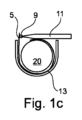
図1a~1eは、実質的に不燃性のラッパー3を有するエアロゾル形成基体20の連続的なラッピングを図示する。図示した実施形態では、実質的に不燃性のラッパーは、積層プロセスによって一緒に結合されてラッパー3を形成する二つの層で形成される。外層は、坪量45グラム/平方メートル(gsm-1)、および厚さ65マイクロメートル(μm)の紙プラグラップである。内層は、坪量17グラム/平方メートル(gsm-1)、および厚さ6.3マイクロメートル(μm)のアルミ箔である。実質的に不燃性のラッパーは、71.3マイクロメートル(μm)の合計厚さを有する。図1aに示すように、エアロゾル形成基体20は、コンベヤーまたはガニチュール13上のラッパー材料の開いたウェブ上に、方向Aに送達される。ラッパー材料3のウェブは、エンボス加工ローラーがラッパーの内表面にテクスチャ加工を施してエンボス加工された部分5を形成する一対のローラー(図示せず)から送達される。エンボス加工された部分5は、ラッパー3の横断方向幅にわたって部分的に延びる。ラッパー3の長軸方向の寸法は、図面の平面に対して垂直である。図1bにおいて、実質的に不燃性のラッパーの一つの端は、エアロゾル形成基体20上に方向Bに折り畳まれる。図1cにおいて、接着剤は、実質的に不燃性のラッパー3の対向する端の内表面上のエンボス加工された部分5に接着剤アプリケータ11によって塗布される。エンボス加工された部分5は、図1dにおける実質的に不燃性のラッパー3の外側紙表面の部分4上に方向Cに折り畳まれる。ここで、アルミ箔層の内表面のエンボス加工された部分5は、実質的に不燃性のラッパー3の紙の外層の部分4と接触する。
1a-1e illustrate continuous wrapping of an aerosol-forming
図1eに示すように、垂直圧力は、実質的に不燃性のラッパー3上に直接Dの方向に加えられて、アルミ箔層のエンボス加工された部分5と実質的に不燃性のラッパー3の紙層の部分4との間の接着を確実にする。エンボス加工された部分5は、非多孔性アルミ箔が、ラッパー部分5とラッパー部分4との間のラップの継ぎ目の領域内にアルミ箔と実質的に不燃性のラッパー3の外側紙との間の問題のない接着のための十分な表面積を有することを確実にする。エンボス加工された部分5がない場合、接着された後に外側の紙表面上にプレスされる内表面である、実質的に不燃性のラッパー3の金属のアルミ箔層は、多孔性ではなく、ラッパー材料の接着に関する問題が生じる。こうした配置では、ラッパーのアルミニウム層は接着剤を吸収するのに十分に多孔性ではなく、したがって、たばこ捲縮機器を出るエアロゾル発生物品上に弱い接着剤の継ぎ目をもたらす。ラッパーの金属のアルミ箔層と紙層との間の弱い接着剤の継ぎ目のために、エアロゾル発生物品の形成を取り扱う捲縮機器およびコンバイナー機器は、性能の低下を体験する可能性がある。例えば、コンバイナーおよび捲縮機の両方は、不良な製品を除去するためにダウンタイムおよび廃棄物の増大を体験し、潜在的に大量の損失をもたらしうる。本発明の実質的に不燃性のラッパー3は、ラッパー内に弱い接着剤の継ぎ目を有する製品で体験する潜在的損失を軽減する。
As shown in FIG. 1e, vertical pressure is applied in the direction D directly onto the substantially
図1eに示すように、エアロゾル形成基体20は、エアロゾル形成基体20および紙プラグラップの外層と接触する、金属の熱伝導性層で形成された実質的に不燃性のラッパー3で巻かれる。層は、積層プロセスで一緒に結合されて、実質的に不燃性のラッパー3を形成しうる。
As shown in FIG. 1e, the aerosol-forming
内側アルミニウム層は、エアロゾル形成基体20と接触する内側層である。この層は熱伝導性機能を有する。別の方法として、または追加的に、内側アルミニウム層は、一体型の熱源上に延びる場合に製品点火を防止しうる。
The inner aluminum layer is the inner layer that contacts the aerosol-forming
実質的に不燃性のラッパー3の外層は紙で作製される。この層は外側にあるため、この層の視覚的な態様および質的な見た目が高水準なものであることが重要である。実質的に不燃性のラッパー3の内層のエンボス加工の部分的な厚さは、紙外層の外観がエンボス加工パターンによって変更されないことを意味する。
The outer layer of the substantially
図2は、本発明の一実施形態によるエアロゾル発生物品10を図示したものである。エアロゾル発生物品10は、同軸に整列して配置された四つの要素、すなわちエアロゾル形成基体20、支持要素30、エアロゾル冷却要素40、およびマウスピース50を含む。これらの四つの要素は連続的に配置され、また外側ラッパー60によって囲まれて、エアロゾル発生物品10を形成する。エアロゾル発生10は、ユーザーが使用中にユーザーの口の中に挿入する近位端または口側端70と、口側端70に対してエアロゾル発生物品10の反対側の端に位置する遠位端80とを有する。
FIG. 2 illustrates an aerosol-generating
使用時に、空気は、ユーザーによってエアロゾル発生物品を通して遠位端80から口側端70に吸い込まれる。エアロゾル発生物品の遠位端80はまた、エアロゾル発生物品10の上流端として記述されてもよく、エアロゾル発生物品10の口側端70はまた、エアロゾル発生物品10の下流端として記述されてもよい。口側端70と遠位端80の間に位置するエアロゾル発生物品10の要素を、口側端70の上流にあると記述することができ、または別の方法として、遠位端80の下流にあると記述することができる。
In use, air is drawn through the aerosol-generating article from the
エアロゾル形成基体20は、エアロゾル発生物品10の最遠の遠位端または上流端に位置する。図2に図示した実施形態において、エアロゾル形成基体20は、実質的に不燃性のラッパー3によって囲まれた、捲縮した均質化したたばこ材料シートの集合体を含む。均質化したたばこ材料の捲縮したシートはエアロゾル形成体としてグリセリンを含む。実質的に不燃性のラッパー3は、紙の外層およびアルミニウムの内層を有する積層プラグラップで形成される。内側アルミニウム層は、実質的に不燃性のラッパー3がエアロゾル形成基体20を囲む時に、紙の外層の一部分と重なる内層のエンボス加工された領域を提供するように、その横断方向幅の一部分にわたってエンボス加工される(テクスチャ加工を施される)。アルミニウムの内層は、塗布される接着剤に対して不浸透性である。アルミニウムの内層の内表面にテクスチャ加工を施すことにより、紙の外層への内層の接着が増大する。増大した接着は、エアロゾル発生物品10の組み立て中の、実質的に不燃性のラッパー3の端間のラップの継ぎ目の開き、または部分的開口を防止する。
Aerosol-forming
支持要素30はエアロゾル形成基体20のすぐ下流に位置し、エアロゾル形成基体20に隣接する。図2に示す実施形態において、支持要素は中空のセルロースアセテートチューブである。支持要素30は、エアロゾル発生装置の発熱体によって貫通されることができるように、エアロゾル発生物品10の最遠の遠位端80にエアロゾル形成基体20を位置させる。支持要素30は、エアロゾル発生装置の発熱体がエアロゾル形成基体20の中へと挿入された時に、エアロゾル形成基体20がエアロゾル冷却要素40の方へエアロゾル発生物品10内に下流へと押し込まれるのを防ぐように作用する。支持要素30はまた、エアロゾル発生物品10のエアロゾル冷却要素40がエアロゾル形成基体20から間隙を介するためのスペーサーとして作用する。
エアロゾル冷却要素40は支持要素30のすぐ下流に位置し、支持要素30に隣接する。使用においては、エアロゾル形成基体20から放出される揮発性物質は、エアロゾル発生物品10の口側端70に向かって、エアロゾル冷却要素40に沿って通過する。揮発性物質は、エアロゾル冷却要素40内で冷却されて、ユーザーが吸入するエアロゾルを形成してもよい。図2に図示した実施形態において、エアロゾル冷却要素は、ラッパー90によって囲まれたポリ乳酸の捲縮したシートの集合体を含む。ポリ乳酸の捲縮したシートの集合体は、エアロゾル冷却要素40の長さに沿って延びる複数の長軸方向チャネルを画定する。
マウスピース50はエアロゾル冷却要素40のすぐ下流に位置し、かつエアロゾル冷却要素40に当接する。図2に図示した実施形態において、マウスピース50は低濾過効率の従来のセルロースアセテートトウフィルターを含む。
エアロゾル発生物品10を組み立てるために、最初にエアロゾル形成基体20が、図1に示す工程に従って、実質的に不燃性のラッパー3内に巻かれうる。次に、巻かれたエアロゾル形成基体20を含む、上述の四つの要素が、外側ラッパー60内に整列されて、緊密に巻かれる。図2に図示した実施形態において、外側ラッパーは従来の紙巻たばこ用紙である。図2に示す通り、穿孔の随意の列は、エアロゾル発生物品10の支持要素30を囲む外側ラッパー60の領域において提供される。
To assemble the aerosol-generating
図2に図示した実施形態において、エアロゾル発生物品10の外側ラッパー60の遠位端部分はチッピングペーパー(図示せず)の帯によって囲まれている。
In the embodiment illustrated in FIG. 2, the distal end portion of the
図2に図示したエアロゾル発生物品10は、ユーザーによって喫煙または消費されるために発熱体を含むエアロゾル発生装置と係合するように設計されている。使用時に、エアロゾル発生装置の発熱体は、エアロゾルを形成するのに十分な温度までエアロゾル発生物品10のエアロゾル形成基体20を加熱し、このエアロゾルがエアロゾル発生物品10を介して下流に引き出され、使用者によって吸入される。
The aerosol-generating
図3は、本発明の一実施形態によるエアロゾル発生物品100を図示したものである。エアロゾル発生物品100は、一体型の熱源25、エアロゾル形成基体20、支持要素30、エアロゾル冷却要素40およびマウスピース50という、同軸に整列して配置される五つの要素を備える。これらの五つの要素は連続的に配置され、また外側ラッパー60によって囲まれて、エアロゾル発生物品10を形成する。図3に図示したエアロゾル発生物品100は、エアロゾル形成基体20の遠位端に一体型の熱源25を含み、これがエアロゾル形成基体20に当接するという点で、図2のエアロゾル発生物品10とは異なっている。実質的に不燃性のラッパー3は、この実施形態ではエアロゾル形成基体20および一体型の熱源25の全長を囲む。炭素熱源25である一体型の熱源25を覆うことによって、実質的に不燃性のラッパー3は、一体型の熱源の点火を防止する。ラッパー3は、点火または作動の前に熱源25から部分的に除去される必要がありうる。
FIG. 3 illustrates an aerosol-generating article 100 according to one embodiment of the invention. Aerosol-generating article 100 comprises five elements arranged in coaxial alignment: an
図3に図示したエアロゾル発生物品100は、ユーザーが物品を喫煙または消費するために、ユーザーに一体型の熱源25を点火させるように設計されている。使用時に、一体型の熱源25は、エアロゾルを形成するのに十分な温度までエアロゾル発生物品100のエアロゾル形成基体20を加熱し、このエアロゾルがエアロゾル発生物品100を介して下流に引き出され、ユーザーによって吸入される。
The aerosol generating article 100 illustrated in FIG. 3 is designed for a user to ignite an
図4は、本発明による装置の一部を形成する一対のローラー(ローラーおよびカウンターローラー)を示している。対のローラーは、エンボス加工表面部分26と滑らかな表面部分28とを有するエンボス加工ローラー27を含む。エンボス加工ローラー表面の一部のみがエンボス加工歯31を含む。使用時に、エンボス加工ローラー27は、ラッパー材料(図示せず)の内側アルミ箔層と接触し、歯31を含むエンボス加工表面部分26は、接着剤が塗布されて二つの部分が図1a~1eに示すように重なった時にラッパー材料の外表面と重なる実質的に不燃性のラッパーの内層の領域を覆う。滑らかな表面のローラー29であるカウンターローラーは、ラッパー材料の外層と接触することになる。滑らかな表面のローラー29は、実質的に不燃性のラッパーの外層がエンボス加工プロセスによって変更されないことを確実にする。
Figure 4 shows a pair of rollers (roller and counterroller) forming part of the device according to the invention. The pair of rollers includes an
一対のローラー27、29のそれぞれは、エアロゾル形成基体捲縮機(図示せず)の下流にある捲縮機器(図示せず)上に取り付け可能なシャフト33a、33b上に取り付けられる。ローラーのシャフト33a、33bは、自由に動く、または電動であってもよい。シャフトが自由に動く場合、ローラーは設置しやすい。
Each of the pair of
ハンドルを使用してオペレーターによって操作されるエンドレスねじ(図示せず)が提供されてもよく、これは、エンボス加工ローラー27と滑らかな表面のローラー29との間の距離の調節を可能にする。ローラー27の表面とローラー29の表面との間の距離を調節することで、ローラー27とローラー29との間を通過する実質的に不燃性のラッパー3の内表面上のエンボス加工の深さが変化する。
An endless screw (not shown) operated by the operator using a handle may be provided, which allows adjustment of the distance between the embossing
図5は、図4の対のローラーを通した処理後の実質的に不燃性のラッパー3のウェブの内表面を図示している。エンボス加工された部分5は、ウェブの全長に沿って延び、実質的に不燃性のラッパーのウェブの横断方向幅にわたって部分的に延びる。実質的に不燃性のラッパー3のウェブの内表面の滑らかな部分2は、滑らかなままである。このようにして、実質的に不燃性のラッパー3の内表面の滑らかな部分は、ラッパー3がエアロゾル形成基体のロッドを囲む時に、エアロゾル形成基体のロッドと密着した接触を形成する。
FIG. 5 illustrates the inner surface of the web of substantially
図6a~8bは、本発明による装置の一部を形成するエンボス加工ローラーのプロファイル付き部分を描写するものである。図9~12bは、本発明による装置の一部を形成するエンボス加工ローラーの代替的なプロファイル付き部分を描写するものである。図13~19は、本発明による装置の一部を形成するエンボス加工ローラーのさらなる代替的なプロファイル付き部分を描写するものである。エンボス加工ローラーの各実施形態における類似の特徴は、因数100だけ大きい、類似の参照番号によって示されている。 Figures 6a-8b depict a profiled section of an embossing roller forming part of an apparatus according to the invention. Figures 9-12b depict alternative profiled portions of an embossing roller forming part of an apparatus according to the invention. Figures 13-19 depict further alternative profiled portions of embossing rollers forming part of an apparatus according to the invention. Similar features in each embodiment of the embossing roller are indicated by similar reference numerals that are increased by a factor of 100.
図6aは、エンボス加工ローラー27のプロファイル付き部分26の端面平面図である。図6bは、プロファイル付き部分26の斜視図である。図6aを参照すると、プロファイル付き部分26の表面は、複数の歯31を含み、隣接した歯31は、エンボス加工ローラー27の外周全体の周りに陥凹部39によって分離されている。45個の歯がエンボス加工ローラー27の外周の周りに配置され、各歯は、エンボス加工ローラーの中空コア35の中心点41を含むローラー27の長軸方向軸から測定して8度の円周角を占める。歯の点に対して測定されるエンボス加工ローラー27の直径は30ミリメートルである。陥凹部39の底部に対して測定されるエンボス加工ローラー27の直径は、28ミリメートルである。図6a~8に図示した実施形態では、歯31は、隣接した陥凹部39の基部から歯31の点まで2ミリメートルの高さである。
FIG. 6a is an end plan view of the profiled
図6bは、プロファイル付き部分26の幅にわたって横断方向に延びる図6aに示す歯のプロファイル付き部分26を示している。当然のことながら、エンボス加工ローラーのプロファイル付き部分26のみが実施形態に示されており、エンボス加工ローラー27の残りの横断方向幅の滑らかな表面は図示されていない。中空コア35は、エンボス加工ローラー27がシャフト(図4の33a、33bを参照)に嵌合することを可能にし、またフランジ37を位置させることによって、シャフトおよびローラー27が一緒に回転することを確実にする。
FIG. 6b shows the profiled
図7は、図6aの線A-Aに沿ったエンボス加工ローラー27のプロファイル付き部分26の断面図である。中空コア35は、位置決めフランジ37を除いて26ミリメートルの直径を有する。歯31および隣接した陥凹部39は、プロファイル付き部分26の幅にわたって延びる。
Figure 7 is a cross-sectional view of the profiled
図8aおよび8bは、Cとして示される領域で取られた図7のプロファイル付き部分の分解図である。各歯31は、陥凹部39の基部において結合された第一の面41および第二の面43を有する。第一の歯31aの第一の面41、および隣接した第二の歯31bの第二の面43は、図示する実施形態では、互いに90度の角度αにある。
8a and 8b are exploded views of the profiled section of FIG. 7 taken in the area designated as C. Each
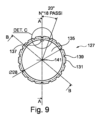
図9は、本発明による装置の一部を形成するエンボス加工ローラー127のプロファイル付き部分126の端面平面図を示している。図9は、エンボス加工ローラー127のプロファイル付き部分126の端面平面図である。図10は、プロファイル付き部分126の斜視図である。図9を参照すると、プロファイル付き部分126の表面は、複数の歯131を含み、隣接した歯131は、エンボス加工ローラー127の外周全体の周りに陥凹部139によって分離されている。各歯131は、平坦な点(先端)を有する。18個の歯131が、エンボス加工ローラー127の外周の周りに配置され、各歯は、エンボス加工ローラーの中空コア135の中心点141を含むローラー127の長軸方向軸から測定して20度の円周角を占める。歯の平坦な点に対して測定されるエンボス加工ローラー127の直径は30ミリメートルである。陥凹部139の底部に対して測定されるエンボス加工ローラー127の直径は、28ミリメートルである。図9~12bに図示した実施形態では、歯131は、隣接した陥凹部139の基部から歯131の平坦な点まで高さ2ミリメートルである。
FIG. 9 shows an end plan view of a profiled
図10は、プロファイル付き部分126の幅にわたって横断方向に延びる図9に示す歯のプロファイル付き部分126を示している。当然のことながら、エンボス加工ローラーのプロファイル付き部分126のみが実施形態に示されており、エンボス加工ローラー127の残りの横断方向幅の滑らかな表面は図示されていない。中空コア135は、エンボス加工ローラー127がシャフト(図4の33a、33bを参照)に嵌合することを可能にし、またフランジ137を位置させることによって、シャフトおよびローラー27が一緒に回転することを確実にする。
FIG. 10 shows the profiled
図11aは、図9の線A-Aで取ったエンボス加工ローラー127のプロファイル付き部分126の断面図であり、図11bは、図9の線B-Bで取ったエンボス加工ローラー127のプロファイル付き部分126の断面図である。中空コア135は、位置決めフランジ137を除いて、26ミリメートルの直径を有する。歯131および隣接した陥凹部139は、プロファイル付き部分126の幅にわたって延びる。
11a is a cross-sectional view of the profiled
図12aは、Cとして示される領域で取られた図11aのプロファイル付き部分の分解図である。各歯131は、陥凹部139の基部において結合された第一の面141および第二の面143を有する。Dとして示される領域で取られた図11bのプロファイル付き部分の分解図である、図12bに図示した通り、第一の歯131aの第一の面141および隣接した第二の歯131bの第二の面143は、図示する実施形態では互いに90度の角度βにある。
FIG. 12a is an exploded view of the profiled section of FIG. 11a taken in the area designated as C. Each
図13は、本発明による装置のなおさらなる実施形態の一部を形成するエンボス加工ローラー227のプロファイル付き部分226の端面平面図を示している。
FIG. 13 shows an end plan view of a profiled
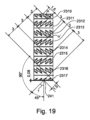
図13は、エンボス加工ローラー227のプロファイル付き部分226の端面平面図である。プロファイル付き部分226の表面は、複数の歯231を含み、隣接した歯231は、エンボス加工ローラー227の外周全体の周りに陥凹部239によって分離されている。図19に最もよく示されるように、各歯231は、その軸が中心点241を含むプロファイル付き部分226の長軸方向軸からオフセットされた先端を有する。オフセット角度γは、図示した実施形態では45度である。このようにして、各歯231の先端は、横断寸法および円周寸法の両方を有する。図19はまた、プロファイル付き部分226の横断方向幅にわたって延びる歯の列を示している。歯の列、2310、2311、2312、2313、2314、2315、2316、2317は、各歯231の先端に沿って測定した時に3ミリメートルの寸法である。隣接した列それぞれにおける歯231の先端は、互いに90度の角度α’にある。
FIG. 13 is an end plan view of the profiled
図13は、エンボス加工ローラー227の外周の周りに列に配置された90個の歯231を示しており、各歯は、エンボス加工ローラーの中空コア235の中心点241を含むローラー227の長軸方向軸から測定して4度の円周角を占めている。歯の点に対して測定されるエンボス加工ローラー227の直径は30ミリメートルである。陥凹部239の底部に対して測定されるエンボス加工ローラー227の直径は、29ミリメートルである。図13~19に図示した実施形態では、歯231は、隣接した陥凹部239の基部から歯231の点まで1ミリメートルの高さである。
FIG. 13 shows ninety
図15は、プロファイル付き部分226の幅にわたって横断方向に延びる歯の列231を含むプロファイル付き部分226を示している。当然のことながら、エンボス加工ローラーのプロファイル付き部分226のみが実施形態に示されており、エンボス加工ローラー227の残りの横断方向幅の滑らかな表面は図示されていない。中空コア235は、エンボス加工ローラー227がシャフト(図4の33a、33bを参照)に嵌合することを可能にし、図16に示す位置決めフランジ237は、シャフトおよびローラー227が一緒に回転することを確実にする。
FIG. 15 shows profiled
図16は、図13の線A-Aに沿って取られたエンボス加工ローラー227のプロファイル付き部分226の断面図である。中空コア235は、位置決めフランジ237を除いて26ミリメートルの直径を有する。歯231および隣接した陥凹部239は、プロファイル付き部分226の幅にわたって延びる。
FIG. 16 is a cross-sectional view of the profiled
図17は、Dとして示される領域で取られた図16のプロファイル付き部分226の分解図である。各歯231は、陥凹部239の基部において結合された第一の面241および第二の面243を有する。第一の歯231aの第一の面243、および隣接した第二の歯231bの第二の面241は、図示する実施形態では互いに90度の角度δにある。
FIG. 17 is an exploded view of the profiled
図14は、図13の領域Bで取られた分解図である。プロファイル付き部分226は、歯の列2310および2311を含み、歯の列が設定される点は、互いに90度の角度にある。
FIG. 14 is an exploded view taken in area B of FIG. Profiled
一緒に陥凹部239を形成する隣接した歯の面241および243は、互いに角度δにある。
Adjacent tooth surfaces 241 and 243, which together form
分かる通り、歯の様々なプロファイルが想定される。各歯の高さは、実質的に不燃性のラッパーの内側熱伝導性層の厚さよりも小さい。このようにして、エンボス加工ローラーは、実質的に不燃性のラッパーの外表面に影響を与えることなく、実質的に不燃性のラッパーの内表面にテクスチャ加工を施すことができる。エンボス加工された表面は、実質的に不燃性のラッパーの厚さ全体を通して、貫通またはそうでなければ破断されない。このようにして、エンボス加工された表面は、実質的に不燃性のラッパーの内層上にテクスチャ加工を施した表面部分を提供し、外層の品質または外観に影響を与えることなく、実質的に不燃性のラッパーの重なり合う層間の接着を改善する。 As can be seen, various tooth profiles are envisaged. The height of each tooth is less than the thickness of the inner thermally conductive layer of the substantially non-flammable wrapper. In this manner, the embossing roller can texture the inner surface of the substantially non-flammable wrapper without affecting the outer surface of the substantially non-flammable wrapper. The embossed surface does not penetrate or otherwise break through the entire thickness of the substantially non-flammable wrapper. In this way, the embossed surface provides a textured surface area on the inner layer of the wrapper that is substantially non-flammable, without affecting the quality or appearance of the outer layer. improves the adhesion between overlapping layers of the plastic wrapper.
エンボス加工されたローラー上の歯の高さは、1ミリメートル以上としうる。実質的に不燃性のラッパーの外層はカウンターローラーの滑らかな表面に対して保持されるため、そして、歯のサイズに関係なく、外層の品質または外観に影響を与えることなくエンボス加工の深さが適宜調節可能でありうるようにローラー間の距離は調整可能であるため、歯の比較的大きな高さ寸法が可能である。 The height of the teeth on the embossed roller may be one millimeter or more. The outer layer of the virtually non-combustible wrapper is held against the smooth surface of the counter roller so that, regardless of tooth size, the depth of embossing can be achieved without affecting the quality or appearance of the outer layer. Since the distance between the rollers is adjustable so that it can be adjusted accordingly, relatively large height dimensions of the teeth are possible.
異なる歯のプロファイルを有する様々なエンボス加工ローラーはそれぞれ、捲縮機器上に固定できる同一のシャフト上に簡単かつ迅速に取り付けることができるように、同一の直径(約8ミリメートル~約36ミリメートル、好ましくは26ミリメートル)の中空コアを有する。ローラーは、シャフトに対するローラーの回転を防止するために、コッターピンを使用してシャフトに固定されうる。 The various embossing rollers with different tooth profiles each have the same diameter (about 8 mm to about 36 mm, preferably has a hollow core of 26 mm). The roller may be secured to the shaft using a cotter pin to prevent rotation of the roller relative to the shaft.
本発明のエアロゾル形成物品を製造するプロセスの間、実質的に不燃性のラッパー材料はエアロゾル形成基体の周りで閉じられ、重なり合う端は接着剤(例えば糊付け)を使用して互いに接着される。接着プロセスは、エアロゾル形成基体を捲縮する(「捲縮機器」(図示しない)によって)ことが関与するより大きなプロセスの一部であってもよく、これは、エアロゾル形成基体および実質的に不燃性のラッパー材料をコンベヤー(図1a~1eの13)上に投入し、コンベヤーは巻かれたエアロゾル形成基体のロッドを排出する。次に、巻かれたエアロゾル形成基体のロッドは、最終製品を形成するように、フィルターおよびその他の構成要素を巻かれたエアロゾル形成基体のロッドと組み合わせる「コンバイナー機器」で使用される。 During the process of making an aerosol-forming article of the invention, a substantially non-flammable wrapper material is closed around the aerosol-forming substrate and the overlapping edges are adhered to each other using an adhesive (eg, gluing). The bonding process may be part of a larger process that involves crimping (by a "crimping device" (not shown)) an aerosol-forming substrate and a substantially non-flammable The plastic wrapper material is deposited onto the conveyor (13 in Figures 1a-1e), which discharges the rolled rod of aerosol-forming substrate. The rod of rolled aerosol-forming substrate is then used in a "combiner device" that combines filters and other components with the rod of wound aerosol-forming substrate to form the final product.
製造プロセスは、実質的に不燃性のラッパーをエアロゾル形成基体のロッドの長軸方向軸の周りに折り畳み、次に、実質的に不燃性のラッパーの内層の内表面の一方の端に沿って継ぎ目に接着剤を塗布した後、実質的に不燃性のラッパーの他方の端の上面上の接着された領域をプレスすることで進みうる。 The manufacturing process involves folding the substantially non-flammable wrapper around the longitudinal axis of the rod of the aerosol-forming substrate and then folding a seam along one edge of the inner surface of the inner layer of the substantially non-flammable wrapper. After applying the adhesive, one may proceed by pressing the adhesive area on the top surface of the other end of the substantially non-flammable wrapper.
図4に示す対のローラーを使用して、例えば、エアロゾル形成基体と接触している層であり、接着プロセスの後に実質的に不燃性のラッパーの外側層と重なる実質的に不燃性のラッパーの内層をエンボス加工して、実質的に不燃性のラッパーの内層の内表面の粗面プロファイルを生成する。エンボス加工は、外層の外表面と重なる領域内の実質的に不燃性のラッパーの内層の表面の接触面積を増大させる。これは、継ぎ目における実質的に不燃性のラッパーの良好な結合を提供する。 Using the pair of rollers shown in FIG. 4, for example, the layer of the substantially non-flammable wrapper that is in contact with the aerosol-forming substrate and which overlaps the outer layer of the substantially non-flammable wrapper after the bonding process. The inner layer is embossed to produce a roughened surface profile of the inner surface of the inner layer of the wrapper that is substantially non-flammable. The embossing increases the contact area of the surface of the inner layer of the substantially non-flammable wrapper in the area that overlaps the outer surface of the outer layer. This provides good bonding of the substantially non-flammable wrapper at the seams.
エアロゾル形成基体を実質的に不燃性のラッパーで巻く間、実質的に不燃性のラッパー材料のウェブは、対のローラーの間で捲縮機器によって引き出されうる。対のローラーのエンボス加工ローラーおよび滑らかな表面のローラーの軸は、実質的に不燃性のラッパー材料のウェブの移動方向と直交するように配向されうる。 While wrapping the aerosol-forming substrate with the substantially non-flammable wrapper, a web of substantially non-flammable wrapper material may be drawn between a pair of rollers by a crimping device. The axes of the embossing roller and the smooth surface roller of the roller pair may be oriented perpendicular to the direction of travel of the web of substantially non-flammable wrapper material.
エンボス加工ローラーのプロファイル付き部分は、ラッパーがエアロゾル形成基体の周りで閉じられた時に、外層に重なる領域内に実質的に不燃性のラッパーの内層上にテクスチャ加工を施した部分を作り出すが、必ずしもすべての内層表面を覆うものではない。このようにして、内層の滑らかな内表面は、エアロゾル形成基体との密着した接触を形成しうる。 The profiled portion of the embossing roller creates, but does not necessarily require, a textured portion on the inner layer of the wrapper that is substantially non-flammable in the area that overlaps the outer layer when the wrapper is closed around the aerosol-forming substrate. It does not cover all inner layer surfaces. In this way, the smooth inner surface of the inner layer can form intimate contact with the aerosol-forming substrate.
エンボス加工ローラー上の歯の高さは、外層の外観がエンボス加工プロセスによって変化しないようなものである。別の方法として、または追加的に、エンボス加工ローラーと滑らかな表面のローラーとの間の距離は、外層の外観がエンボス加工プロセスによって変化しないようなものである。 The height of the teeth on the embossing roller is such that the appearance of the outer layer is not changed by the embossing process. Alternatively or additionally, the distance between the embossing roller and the smooth surface roller is such that the appearance of the outer layer is not changed by the embossing process.
実質的に不燃性のラッパーの滑らかな外層に対する内層のエンボス加工された非多孔性(例えば、金属)部分の改善された接着の結果として、エアロゾル形成基体のラッパーのロッドの品質が改善され、廃棄物または不合格の製品の量が減少しうる。 As a result of improved adhesion of the embossed non-porous (e.g. metal) portion of the inner layer to the smooth outer layer of the substantially non-flammable wrapper, the quality of the rods of the wrapper on the aerosol-forming substrate is improved, making it easier to dispose of. The amount of waste or rejected product may be reduced.
本明細書の記述および特許請求の範囲全体を通して、「備える」および「含む」およびそれらの変形は、「含むが、これらに限定されない」を意味し、その他の部分、添加物、構成要素、整数または工程を除外することを意図しない(および除外しない)ことを意味する。本明細書の記述および特許請求の範囲全体を通して、単数形は複数形を包含するが、そうでないことを文脈が要求する場合はその限りではない。特に、不定冠詞が使用される場合、本明細書は、複数ならびに単数を企図するとして理解されるべきであるが、そうでないことを文脈が要求する場合はその限りではない。 Throughout the description and claims of this specification, "comprising" and "including" and variations thereof mean "including, but not limited to," other moieties, additives, components, integers, etc. or does not mean (and does not exclude) a process. Throughout the description and claims of this specification, the singular encompasses the plural unless the context otherwise requires. In particular, when the indefinite article is used, the specification is to be understood as contemplating the plural as well as the singular, unless the context otherwise requires.
本発明の特定の態様、実施形態または実施例と併せて説明される機能、整数、特徴、化合物、化学的部分または基は、それらと不適合でない限り、本明細書に記載される任意の他の態様、実施形態または実施例に適用できることが理解されるべきである。本明細書に開示される特徴のすべて(付随する請求項、要約および図面を含む)、および/または開示される任意の方法またはプロセスのすべての工程は、こうした特徴および/または工程の少なくとも一部が相互に排他的である場合を除き、任意の組み合わせで組み合わせられてもよい。本発明は、いかなる前述の実施形態の詳細にも制限されない。本発明は、本明細書(すべての添付の請求項、要約および図面を含む)に開示された特徴の任意の新規のもの、もしくは任意の組み合わせ、または開示された任意の方法もしくはプロセスの任意の新規のものもしくは任意の新規の組み合わせに拡大解釈する。 A feature, integer, characteristic, compound, chemical moiety or group described in conjunction with a particular aspect, embodiment or example of the invention may be used in conjunction with any other feature described herein, unless it is incompatible therewith. It should be understood that any aspect, embodiment or example may apply. All of the features disclosed herein (including the accompanying claims, abstract, and drawings) and/or all steps of any method or process disclosed may include at least some of such features and/or steps. may be combined in any combination unless they are mutually exclusive. The invention is not limited to the details of any previously described embodiments. The invention resides in any novelty or combination of features disclosed in this specification (including any appended claims, abstract and drawings) or any method or process disclosed. Extend interpretation to new things or arbitrary new combinations.
Claims (14)
エアロゾル形成基体と、
前記エアロゾル形成基体を囲み、内表面および外表面を含む、実質的に不燃性のラッパーと、を含み、
前記ラッパーの前記内表面が、前記ラッパーが前記エアロゾル形成基体の周りに巻かれた時に、前記ラッパーの前記外表面の一部分と重なるように構成された少なくとも部分的にテクスチャ加工を施した表面であって、接着剤が塗布された前記少なくとも部分的にテクスチャ加工を施した表面を有し、前記少なくとも部分的にテクスチャ加工を施した表面が前記エアロゾル形成基体の前記周りに部分的に延びる、エアロゾル発生物品。 An aerosol-generating article for use in an aerosol-generating device including a heating element, the aerosol-generating article comprising:
an aerosol-forming substrate;
a substantially non-flammable wrapper surrounding the aerosol-forming substrate and including an inner surface and an outer surface;
the inner surface of the wrapper is an at least partially textured surface configured to overlap a portion of the outer surface of the wrapper when the wrapper is wrapped around the aerosol-forming substrate; the at least partially textured surface having an adhesive applied thereto , the at least partially textured surface extending partially around the circumference of the aerosol-forming substrate; Goods.
前記エアロゾル形成基体の上流端にあり、作動した時にエアロゾルを形成するように前記エアロゾル形成基体を加熱するように配置される、発熱体と、
前記エアロゾル形成基体および前記発熱体の少なくとも一部分を囲む実質的に不燃性のラッパーであって、前記ラッパーが内表面および外表面を含む、実質的に不燃性のラッパーと、を含み、
前記ラッパーの前記内表面が、前記ラッパーが前記エアロゾル形成基体の周りに巻かれた時に、前記ラッパーの前記外表面の一部分と重なるように構成された少なくとも部分的にテクスチャ加工を施した表面であって、接着剤が塗布された前記少なくとも部分的にテクスチャ加工を施した表面を有し、前記少なくとも部分的にテクスチャ加工を施した表面が前記エアロゾル形成基体の前記周りに部分的に延びる、エアロゾル発生物品。 an aerosol-forming substrate comprising one or more of tobacco and a nicotine source;
a heating element at the upstream end of the aerosol-forming substrate and positioned to heat the aerosol-forming substrate to form an aerosol when activated;
a substantially non-flammable wrapper surrounding at least a portion of the aerosol-forming substrate and the heating element, the wrapper including an inner surface and an outer surface;
the inner surface of the wrapper is an at least partially textured surface configured to overlap a portion of the outer surface of the wrapper when the wrapper is wrapped around the aerosol-forming substrate; the at least partially textured surface having an adhesive applied thereto , the at least partially textured surface extending partially around the circumference of the aerosol-forming substrate; Goods.
Applications Claiming Priority (3)
| Application Number | Priority Date | Filing Date | Title |
|---|---|---|---|
| EP18180249 | 2018-06-27 | ||
| EP18180249.7 | 2018-06-27 | ||
| PCT/EP2019/066548 WO2020002165A1 (en) | 2018-06-27 | 2019-06-21 | Aerosol-generating article and apparatus for forming an aerosol-generating article |
Publications (2)
| Publication Number | Publication Date |
|---|---|
| JP2021530200A JP2021530200A (en) | 2021-11-11 |
| JP7344228B2 true JP7344228B2 (en) | 2023-09-13 |
Family
ID=62814919
Family Applications (1)
| Application Number | Title | Priority Date | Filing Date |
|---|---|---|---|
| JP2020568762A Active JP7344228B2 (en) | 2018-06-27 | 2019-06-21 | Aerosol-generating articles and apparatus for forming aerosol-generating articles |
Country Status (9)
| Country | Link |
|---|---|
| US (1) | US12114690B2 (en) |
| EP (1) | EP3813572B1 (en) |
| JP (1) | JP7344228B2 (en) |
| KR (1) | KR102841359B1 (en) |
| CN (1) | CN112218548B (en) |
| ES (1) | ES3034782T3 (en) |
| MX (1) | MX2020013333A (en) |
| PL (1) | PL3813572T3 (en) |
| WO (1) | WO2020002165A1 (en) |
Families Citing this family (20)
| Publication number | Priority date | Publication date | Assignee | Title |
|---|---|---|---|---|
| GB202009165D0 (en) * | 2020-06-16 | 2020-07-29 | Nicoventures Trading Ltd | Article for use in a non-combustile aerosol provision system |
| GB202009163D0 (en) * | 2020-06-16 | 2020-07-29 | Nicoventures Trading Ltd | Article for use in non-combustible aerosol provision system |
| JPWO2022102049A1 (en) | 2020-11-12 | 2022-05-19 | ||
| EP4245158A1 (en) | 2020-11-12 | 2023-09-20 | Japan Tobacco Inc. | Flavor generating article |
| WO2022102046A1 (en) | 2020-11-12 | 2022-05-19 | 日本たばこ産業株式会社 | Flavor-generating article |
| WO2022112576A1 (en) * | 2020-11-27 | 2022-06-02 | Philip Morris Products S.A. | Aerosol-generating article having wrapper comprising an embossed portion |
| EP4250966B1 (en) * | 2020-11-27 | 2026-04-01 | Philip Morris Products S.A. | Aerosol-generating article having a wrapper |
| WO2022112575A1 (en) * | 2020-11-27 | 2022-06-02 | Philip Morris Products S.A. | Aerosol-generating article comprising a wrapper |
| US20240365846A1 (en) * | 2021-04-12 | 2024-11-07 | Philip Morris Products S.A. | Aerosol-generating article comprising a dual-layer wrapping structure |
| BR112023020951A2 (en) * | 2021-04-12 | 2023-12-12 | Philip Morris Products Sa | AEROSOL GENERATING ARTICLE COMPRISING AN ENCLOSURE WITH AN OVERLAPPING REGION |
| WO2022224435A1 (en) * | 2021-04-23 | 2022-10-27 | 日本たばこ産業株式会社 | Method for producing cartridge for flavor inhaler |
| KR102854664B1 (en) * | 2021-10-29 | 2025-09-03 | 주식회사 케이티앤지 | Cigarette and device for generating aerosol with the same |
| WO2023089803A1 (en) | 2021-11-22 | 2023-05-25 | 日本たばこ産業株式会社 | Flavor-generating substance and smoking system |
| US20250031749A1 (en) * | 2021-11-29 | 2025-01-30 | Philip Morris Products S.A. | Aerosol-generating article having wrapper comprising an adhesive |
| KR20230101132A (en) * | 2021-12-29 | 2023-07-06 | 주식회사 케이티앤지 | Medium segment, aerosol forming article and system comprising the same |
| EP4616736A1 (en) | 2022-11-11 | 2025-09-17 | Japan Tobacco Inc. | Flavor-generating article and flavor inhalation system |
| KR20250088583A (en) | 2022-11-11 | 2025-06-17 | 니뽄 다바코 산교 가부시키가이샤 | Flavor producing article |
| KR20250122499A (en) | 2022-12-26 | 2025-08-13 | 니뽄 다바코 산교 가부시키가이샤 | Flavor inhalation system |
| EP4648627A1 (en) | 2023-01-12 | 2025-11-19 | N2B Limited | Smoking capsule with resistive heating element |
| DE102023132802A1 (en) * | 2023-11-24 | 2025-05-28 | Marcel P. HOFSAESS | Shrink cap and method for producing a shrink cap |
Citations (6)
| Publication number | Priority date | Publication date | Assignee | Title |
|---|---|---|---|---|
| JP2013521814A (en) | 2010-03-22 | 2013-06-13 | ブリティッシュ アメリカン タバコ (インヴェストメンツ) リミテッド | Low-ignition smoking article wrapper, smoking article, and method and apparatus for producing the same |
| JP2015502159A (en) | 2011-12-23 | 2015-01-22 | タンパピエル ゲゼルシャフト ミット ベシュレンクテル ハフツングTannpapier GmbH | Mouthpiece lining paper formed as a film / foil of cigarettes with filters |
| JP2016523567A (en) | 2013-07-18 | 2016-08-12 | フィリップ・モーリス・プロダクツ・ソシエテ・アノニム | Method of manufacturing airflow directing segments for smoking articles |
| WO2017036951A1 (en) | 2015-08-31 | 2017-03-09 | British American Tobacco (Investments) Limited | Article for use with apparatus for heating smokable material |
| WO2018007257A1 (en) | 2016-07-07 | 2018-01-11 | Jt International S.A. | Smoking article and method of manufacturing same |
| JP2018514194A (en) | 2015-03-31 | 2018-06-07 | フィリップ・モーリス・プロダクツ・ソシエテ・アノニム | Smoking article comprising a wrapper having a plurality of protrusions on the inner surface |
Family Cites Families (16)
| Publication number | Priority date | Publication date | Assignee | Title |
|---|---|---|---|---|
| US2890704A (en) * | 1954-11-10 | 1959-06-16 | William R Lamm | Cigarette |
| US4955397A (en) * | 1989-07-10 | 1990-09-11 | Brown & Williamson Tobacco Corporation | Cigarette |
| EP1318728A2 (en) * | 2000-09-18 | 2003-06-18 | Rothmans, Benson & Hedges Inc. | Low sidestream smoke cigarette with non-combustible treatment material |
| US20050172976A1 (en) | 2002-10-31 | 2005-08-11 | Newman Deborah J. | Electrically heated cigarette including controlled-release flavoring |
| KR100728489B1 (en) * | 2005-11-24 | 2007-06-14 | 박신택 | Tabacco have incombustible sheet |
| JP2011205916A (en) * | 2010-03-29 | 2011-10-20 | British American Tobacco (Investments) Ltd | Smoking article and method of manufacturing smoking article |
| GB2479775A (en) * | 2010-04-22 | 2011-10-26 | British American Tobacco Co | Embossing smoking article wrappers |
| CA2837953C (en) | 2011-05-31 | 2020-06-16 | Philip Morris Products S.A. | Rods for use in smoking articles |
| EP2731717A1 (en) | 2011-07-12 | 2014-05-21 | Dow Corning Corporation | Lanthanide complexes with imidazole ligands for condensation reactions |
| EP2757912B1 (en) * | 2011-09-20 | 2022-08-10 | R. J. Reynolds Tobacco Company | Segmented smoking article with substrate cavity |
| TW201438607A (en) * | 2012-10-16 | 2014-10-16 | British American Tobacco Co | Smoking article wrapper and method of making a smoking article |
| PL2961286T3 (en) * | 2013-02-27 | 2018-01-31 | Philip Morris Products Sa | Smoking article having hidden indicia |
| UA119333C2 (en) * | 2013-12-05 | 2019-06-10 | Філіп Морріс Продактс С.А. | HEATING PRODUCT GENERATED BY AEROSOL WITH HEAT DISTRIBUTION WRAP |
| UA118857C2 (en) | 2013-12-05 | 2019-03-25 | Філіп Морріс Продактс С.А. | Thermal laminate rods for use in aerosol-generating articles |
| DE102015118595A1 (en) * | 2015-10-30 | 2017-06-01 | Axagarius Gmbh & Co. Kg | Marked filter paper for use as a test substrate in the case of standardized methods for assessing the ignition tendency of cigarettes |
| WO2018037048A1 (en) * | 2016-08-26 | 2018-03-01 | Philip Morris Products S.A. | Aerosol-generating article comprising an aerosol-forming substrate and a heat-conducting element |
-
2019
- 2019-06-21 KR KR1020207034989A patent/KR102841359B1/en active Active
- 2019-06-21 ES ES19732652T patent/ES3034782T3/en active Active
- 2019-06-21 WO PCT/EP2019/066548 patent/WO2020002165A1/en not_active Ceased
- 2019-06-21 CN CN201980037941.3A patent/CN112218548B/en active Active
- 2019-06-21 PL PL19732652.3T patent/PL3813572T3/en unknown
- 2019-06-21 US US17/251,357 patent/US12114690B2/en active Active
- 2019-06-21 EP EP19732652.3A patent/EP3813572B1/en active Active
- 2019-06-21 MX MX2020013333A patent/MX2020013333A/en unknown
- 2019-06-21 JP JP2020568762A patent/JP7344228B2/en active Active
Patent Citations (6)
| Publication number | Priority date | Publication date | Assignee | Title |
|---|---|---|---|---|
| JP2013521814A (en) | 2010-03-22 | 2013-06-13 | ブリティッシュ アメリカン タバコ (インヴェストメンツ) リミテッド | Low-ignition smoking article wrapper, smoking article, and method and apparatus for producing the same |
| JP2015502159A (en) | 2011-12-23 | 2015-01-22 | タンパピエル ゲゼルシャフト ミット ベシュレンクテル ハフツングTannpapier GmbH | Mouthpiece lining paper formed as a film / foil of cigarettes with filters |
| JP2016523567A (en) | 2013-07-18 | 2016-08-12 | フィリップ・モーリス・プロダクツ・ソシエテ・アノニム | Method of manufacturing airflow directing segments for smoking articles |
| JP2018514194A (en) | 2015-03-31 | 2018-06-07 | フィリップ・モーリス・プロダクツ・ソシエテ・アノニム | Smoking article comprising a wrapper having a plurality of protrusions on the inner surface |
| WO2017036951A1 (en) | 2015-08-31 | 2017-03-09 | British American Tobacco (Investments) Limited | Article for use with apparatus for heating smokable material |
| WO2018007257A1 (en) | 2016-07-07 | 2018-01-11 | Jt International S.A. | Smoking article and method of manufacturing same |
Also Published As
| Publication number | Publication date |
|---|---|
| US20210244079A1 (en) | 2021-08-12 |
| MX2020013333A (en) | 2021-03-09 |
| KR20210024455A (en) | 2021-03-05 |
| EP3813572B1 (en) | 2025-06-04 |
| ES3034782T3 (en) | 2025-08-22 |
| EP3813572A1 (en) | 2021-05-05 |
| EP3813572C0 (en) | 2025-06-04 |
| PL3813572T3 (en) | 2025-08-18 |
| WO2020002165A1 (en) | 2020-01-02 |
| BR112020024275A2 (en) | 2021-02-23 |
| CN112218548B (en) | 2023-04-04 |
| US12114690B2 (en) | 2024-10-15 |
| JP2021530200A (en) | 2021-11-11 |
| CN112218548A (en) | 2021-01-12 |
| KR102841359B1 (en) | 2025-08-01 |
Similar Documents
| Publication | Publication Date | Title |
|---|---|---|
| JP7344228B2 (en) | Aerosol-generating articles and apparatus for forming aerosol-generating articles | |
| US12433320B2 (en) | Method and apparatus for manufacturing a crimped web | |
| JP6820990B2 (en) | Smoking goods and related manufacturing methods | |
| JP7162536B2 (en) | Electrically-operated aerosol-generating system with tubular aerosol-generating article having improved airflow | |
| KR102400324B1 (en) | Non-tobacco nicotine-containing article | |
| EP3076811B1 (en) | Heated aerosol generating article with thermal spreading endpiece | |
| AU2014359188A1 (en) | Thermal laminate rods for use in aerosol-generating articles | |
| JP2015519915A (en) | Smoking articles for use with internal heating elements | |
| KR20160096590A (en) | Heated aerosol generating article with thermal spreading wrap | |
| WO2019030272A1 (en) | Aerosol-generating article having rod with multiple sheets of tobacco material | |
| RS57128B1 (en) | Thermally conducting rods for use in aerosol-generating articles | |
| TW201334715A (en) | Aerosol-generating article having biodegradeble flavour-generating component | |
| RU2791707C2 (en) | Aerosol generating unit (versions), device and method for forming aerosol generating unit embossed wrap and method for forming aerosol generating unit | |
| JP7692060B2 (en) | Components for use in flammable aerosol delivery systems | |
| TW202306502A (en) | Aerosol generating system | |
| BR112020024275B1 (en) | AEROSOL GENERATOR ARTICLE | |
| HK1223518B (en) | Heated aerosol generating article with thermal spreading endpiece |
Legal Events
| Date | Code | Title | Description |
|---|---|---|---|
| A521 | Request for written amendment filed |
Free format text: JAPANESE INTERMEDIATE CODE: A523 Effective date: 20210121 |
|
| A621 | Written request for application examination |
Free format text: JAPANESE INTERMEDIATE CODE: A621 Effective date: 20220617 |
|
| A977 | Report on retrieval |
Free format text: JAPANESE INTERMEDIATE CODE: A971007 Effective date: 20230414 |
|
| A131 | Notification of reasons for refusal |
Free format text: JAPANESE INTERMEDIATE CODE: A131 Effective date: 20230417 |
|
| A521 | Request for written amendment filed |
Free format text: JAPANESE INTERMEDIATE CODE: A523 Effective date: 20230718 |
|
| TRDD | Decision of grant or rejection written | ||
| A01 | Written decision to grant a patent or to grant a registration (utility model) |
Free format text: JAPANESE INTERMEDIATE CODE: A01 Effective date: 20230803 |
|
| A61 | First payment of annual fees (during grant procedure) |
Free format text: JAPANESE INTERMEDIATE CODE: A61 Effective date: 20230901 |
|
| R150 | Certificate of patent or registration of utility model |
Ref document number: 7344228 Country of ref document: JP Free format text: JAPANESE INTERMEDIATE CODE: R150 |