CN112218548A - Aerosol-generating articles and apparatus for forming aerosol-generating articles - Google Patents
Aerosol-generating articles and apparatus for forming aerosol-generating articles Download PDFInfo
- Publication number
- CN112218548A CN112218548A CN201980037941.3A CN201980037941A CN112218548A CN 112218548 A CN112218548 A CN 112218548A CN 201980037941 A CN201980037941 A CN 201980037941A CN 112218548 A CN112218548 A CN 112218548A
- Authority
- CN
- China
- Prior art keywords
- aerosol
- wrapper
- forming substrate
- generating article
- combustible
- Prior art date
- Legal status (The legal status is an assumption and is not a legal conclusion. Google has not performed a legal analysis and makes no representation as to the accuracy of the status listed.)
- Granted
Links
Images


Classifications
-
- A—HUMAN NECESSITIES
- A24—TOBACCO; CIGARS; CIGARETTES; SIMULATED SMOKING DEVICES; SMOKERS' REQUISITES
- A24C—MACHINES FOR MAKING CIGARS OR CIGARETTES
- A24C5/00—Making cigarettes; Making tipping materials for, or attaching filters or mouthpieces to, cigars or cigarettes
- A24C5/005—Treatment of cigarette paper
-
- A—HUMAN NECESSITIES
- A24—TOBACCO; CIGARS; CIGARETTES; SIMULATED SMOKING DEVICES; SMOKERS' REQUISITES
- A24D—CIGARS; CIGARETTES; TOBACCO SMOKE FILTERS; MOUTHPIECES OF CIGARS OR CIGARETTES; MANUFACTURE OF TOBACCO SMOKE FILTERS OR MOUTHPIECES
- A24D1/00—Cigars; Cigarettes
- A24D1/02—Cigars; Cigarettes with special covers
- A24D1/025—Cigars; Cigarettes with special covers the covers having material applied to defined areas, e.g. bands for reducing the ignition propensity
-
- A—HUMAN NECESSITIES
- A24—TOBACCO; CIGARS; CIGARETTES; SIMULATED SMOKING DEVICES; SMOKERS' REQUISITES
- A24D—CIGARS; CIGARETTES; TOBACCO SMOKE FILTERS; MOUTHPIECES OF CIGARS OR CIGARETTES; MANUFACTURE OF TOBACCO SMOKE FILTERS OR MOUTHPIECES
- A24D1/00—Cigars; Cigarettes
- A24D1/20—Cigarettes specially adapted for simulated smoking devices
-
- D—TEXTILES; PAPER
- D21—PAPER-MAKING; PRODUCTION OF CELLULOSE
- D21H—PULP COMPOSITIONS; PREPARATION THEREOF NOT COVERED BY SUBCLASSES D21C OR D21D; IMPREGNATING OR COATING OF PAPER; TREATMENT OF FINISHED PAPER NOT COVERED BY CLASS B31 OR SUBCLASS D21G; PAPER NOT OTHERWISE PROVIDED FOR
- D21H27/00—Special paper not otherwise provided for, e.g. made by multi-step processes
- D21H27/30—Multi-ply
-
- D—TEXTILES; PAPER
- D21—PAPER-MAKING; PRODUCTION OF CELLULOSE
- D21H—PULP COMPOSITIONS; PREPARATION THEREOF NOT COVERED BY SUBCLASSES D21C OR D21D; IMPREGNATING OR COATING OF PAPER; TREATMENT OF FINISHED PAPER NOT COVERED BY CLASS B31 OR SUBCLASS D21G; PAPER NOT OTHERWISE PROVIDED FOR
- D21H5/00—Special paper or cardboard not otherwise provided for
- D21H5/02—Patterned paper
- D21H5/06—Apparatus
-
- D—TEXTILES; PAPER
- D21—PAPER-MAKING; PRODUCTION OF CELLULOSE
- D21H—PULP COMPOSITIONS; PREPARATION THEREOF NOT COVERED BY SUBCLASSES D21C OR D21D; IMPREGNATING OR COATING OF PAPER; TREATMENT OF FINISHED PAPER NOT COVERED BY CLASS B31 OR SUBCLASS D21G; PAPER NOT OTHERWISE PROVIDED FOR
- D21H5/00—Special paper or cardboard not otherwise provided for
- D21H5/12—Special paper or cardboard not otherwise provided for characterised by the use of special fibrous materials
- D21H5/14—Special paper or cardboard not otherwise provided for characterised by the use of special fibrous materials of cellulose fibres only
- D21H5/16—Tobacco or cigarette paper
Landscapes
- Cigarettes, Filters, And Manufacturing Of Filters (AREA)
- Manufacturing Of Cigar And Cigarette Tobacco (AREA)
- Resistance Heating (AREA)
- Nozzles (AREA)
- Containers And Packaging Bodies Having A Special Means To Remove Contents (AREA)
- Catching Or Destruction (AREA)
Abstract
The present invention relates to an aerosol-generating article (10) for use with an aerosol-generating device comprising a heating element, or with an integral heat source, the aerosol-generating article (10) comprising: an aerosol-forming substrate (20); a substantially non-combustible wrapper (3) surrounding the aerosol-forming substrate (20) and comprising an inner surface and an outer surface, wherein the inner surface of the wrapper (3) has an at least partially textured surface (5) configured to overlap a portion of the outer surface (4) of the wrapper (3) when the wrapper (3) is wrapped around the aerosol-forming substrate (20). The invention also relates to an apparatus and a method for forming an aerosol-generating article (10).
Description
Technical Field
The present invention relates to an aerosol-generating article comprising an aerosol-forming substrate for generating an inhalable aerosol when heated by a heating element or an integral heating element of an aerosol-generating device. The invention also relates to an apparatus for manufacturing such an aerosol-generating article and to a method of manufacturing such an aerosol-generating article.
Background
Many smoking articles in which tobacco is heated rather than combusted are proposed in the art. One purpose of such heated smoking articles is to reduce harmful smoke constituents of the known type produced by the combustion and pyrolytic degradation of tobacco in conventional cigarettes.
Typically in such heated smoking articles, the aerosol is generated by transferring heat from a heat source to a physically separate aerosol-forming substrate or material, which may be located within, around or downstream of the heat source. During smoking, volatile compounds are released from the aerosol-forming substrate by heat transfer from the heat source and become entrained in the air drawn through the smoking article. As the released compound cools, the compound condenses to form an aerosol that is inhaled by the user.
A number of prior art documents disclose aerosol-generating devices for consuming or smoking heated smoking articles. Such devices include, for example, electrically heated aerosol-generating devices in which an aerosol is generated by transferring heat from one or more electrical heating elements of the aerosol-generating device to an aerosol-forming substrate of a heated smoking article. One advantage of such electrical smoking systems is that they greatly reduce sidestream smoke, while allowing the user to selectively suspend and resume smoking.
An example of an electrically heated cigarette for use in an electrical smoking system is disclosed in US 2005/0172976 a 1. The electrically heated cigarette is configured to be insertable into a cigarette receptacle of a reusable lighter of an electrical smoking system. The lighter includes a power source that supplies energy to a heater fixture that includes a plurality of resistive heating elements arranged to slidably receive the cigarette such that the heating elements are positioned alongside the cigarette. The electrically heated cigarette used in the electrical smoking system disclosed in US 2005/0172976 a1 may use pulsed heating to provide energy to the electrically heated cigarette.
As mentioned above, the electrically heated cigarette disclosed in US 2005/0172976 a1 is used in an electrical smoking system comprising a plurality of external heating elements. Electronic smoking systems comprising aerosol-generating devices with internal heating elements are also known. In use, the internal heating element of the aerosol-generating device of such an electrical smoking system is inserted into the aerosol-forming substrate of the heated smoking article such that the internal heating element is in direct contact with the aerosol-forming substrate.
Direct contact between an internal heating element of an aerosol-generating device and an aerosol-forming substrate of a heated smoking article may provide an effective means for heating the aerosol-forming substrate to form an inhalable aerosol. In such a configuration, heat from the internal heating element may be delivered almost immediately to at least a portion of the aerosol-forming substrate when the internal heating element is actuated, and this may facilitate rapid generation of an aerosol. Furthermore, the total heating energy required to generate the aerosol may be lower than in a smoking system comprising an external heater element, whether or not the aerosol-forming substrate is not in direct contact with the external heater element, and the initial heating of the aerosol-forming substrate occurs by convection or radiation. In the case where the internal heating element of the aerosol-generating device is in direct contact with the aerosol-forming substrate, the initial heating of the portion of the aerosol-forming substrate in direct contact with the internal heating element will be achieved by conduction.
In alternative heated smoking articles, the aerosol is generated by heat transfer from a heat source forming part of the heated smoking article, the heat source being adjacent to the aerosol-forming substrate or material. The heat source may be located within, around or most typically upstream of the aerosol-forming substrate or material.
Where the heat source of the heated smoking article is in direct contact with the aerosol-forming substrate, initial heating of the portion of the aerosol-forming substrate in direct contact with the heat source will be achieved by conduction.
Disclosure of Invention
The present invention provides at least an alternative to prior art aerosol-generating articles. In particular, the present invention relates to an aerosol-generating article comprising an aerosol-forming substrate for generating an inhalable aerosol when heated by an internal or external heating element. The invention also relates to an apparatus and a method for manufacturing such an aerosol-generating article.
Aspects of the invention provide an aerosol-generating article for use with an aerosol-generating device comprising a heating element, an aerosol-generating article comprising a heating element, and an apparatus and method for forming an embossed package for enclosing an aerosol-forming substrate according to the appended claims.
According to an aspect of the present invention, there is provided an aerosol-generating article for use with an aerosol-generating device comprising a heating element, the aerosol-generating article comprising: an aerosol-forming substrate; a substantially non-flammable wrapper surrounding the aerosol-forming substrate and comprising an inner surface and an outer surface, wherein the inner surface of the wrapper has an at least partially textured surface configured to overlap a portion of the outer surface of the wrapper when the wrapper is wrapped around the aerosol-forming substrate. In this manner, the textured surface may be bonded to the outer surface of the wrapper. Without wishing to be bound by theory, the textured surface increases the surface area over which the adhesive can be applied, thereby increasing the adhesion between the inner and outer surfaces of the wrapper material. Thus, when the textured surface is bonded to the outer surface by the adhesive, separation of the inner and outer surfaces of the wrapper is avoided.
According to another aspect of the present invention there is provided an aerosol-generating article comprising: an aerosol-forming substrate comprising one or more of tobacco and a nicotine source; a heating element at an upstream end of the aerosol-forming substrate and arranged to heat the aerosol-forming substrate so as to form an aerosol when actuated; a substantially non-combustible wrapper surrounding the aerosol-forming substrate and at least a portion of the heating element, the wrapper comprising an inner surface and an outer surface; wherein the inner surface of the wrapper has an at least partially textured surface configured to overlap a portion of the outer surface of the wrapper when the wrapper is wrapped around the aerosol-forming substrate. Thus, when the textured surface is bonded to the outer surface by the adhesive, separation of the inner and outer surfaces of the wrapper is avoided.
As used herein, "substantially non-combustible package" is used to describe a package comprising a thermally conductive non-combustible layer.
In certain embodiments, the at least partially textured surface is embossed. More specifically, the embossing surface comprises a pattern of raised and recessed portions of a substantially non-combustible wrapper material.
In certain embodiments, the pattern of raised and recessed portions of the substantially non-combustible wrapper material is a regular pattern.
As used herein, the term "regular pattern" is used to describe a pattern comprising a regular array of raised and recessed portions of a substantially non-combustible wrapper material.
In certain embodiments, the pattern of raised and recessed portions of the substantially non-combustible wrapper material is an irregular pattern.
As used herein, the term "irregular pattern" is used to describe a pattern comprising a non-repeating or random array of raised and recessed portions of a substantially non-flammable wrapper material.
In certain embodiments, the textured surface is formed by deforming the wrapper. For example, the textured surface may be formed by embossing, or pressing the wrapper.
In certain embodiments, the substantially non-combustible wrapper has a smooth outer surface. That is, the texture of the inner surface extends through a portion of the thickness of the wrapper. In this way, the visual integrity of the overwrap visible to the user remains unchanged. The textured surface of the inner surface does not affect the overall appearance of the product.
In certain embodiments, the substantially non-combustible wrapper having a textured surface extends partially around the circumference of the aerosol-forming substrate. More specifically, the inner surface of the substantially non-combustible wrapper includes a textured portion and a smooth portion. More specifically, the substantially non-combustible wrapper includes a longitudinal strip of textured portions and a longitudinal strip of smooth portions.
In certain embodiments, the textured portion extends along an edge of the substantially non-combustible wrapper. More specifically, the textured portion extends along a longitudinal edge of the substantially non-combustible wrapper. In this way, the textured portion forms a portion of the inner surface of the wrapper which will overlap the outer surface of the opposite edge of the wrapper when the wrapper is wrapped around the aerosol-forming substrate. Thus, the texture on the inner package does not affect the portion of the package in contact with the aerosol-forming substrate. More specifically, a smooth portion of the inner surface of the substantially non-combustible wrapper is in contact with the aerosol-forming substrate, and a textured portion of the inner surface of the substantially non-combustible wrapper forms a wrapper seam with a portion of the outer surface of the substantially non-combustible wrapper when the wrapper surrounds the aerosol-forming substrate. In this way, the adhesive strength of the wrapper seam is increased without altering the wrapper surface at the interface with the aerosol-forming substrate.
In certain embodiments, the textured portion has a width of between about 10 millimeters and about 20 millimeters. More specifically, the width of the textured portion may be 15 mm. The width of this portion is measured across the transverse (shorter) dimension of the substantially non-combustible wrapper. In this way, when the wrapper is wrapped around the aerosol-forming substrate, a textured portion is provided at the overlap between the edges of the wrapper. Thus, the textured portion forms one surface of the seam between the inner and outer surfaces of the wrapper.
In certain embodiments, the textured portion is completely covered by the outer surface of the wrapper when the wrapper surrounds the aerosol-forming substrate. In this way, the textured portion does not damage the inner or outer surface of the wrapper when the wrapper surrounds the aerosol-forming substrate.
In certain embodiments, a portion of the inner surface of the substantially non-combustible wrapper having the textured surface overlaps a portion of the outer surface of the substantially non-combustible wrapper. More specifically, a portion of the inner surface of the substantially non-combustible wrapper having a textured surface overlaps and is bonded to a portion of the outer surface of the substantially non-combustible wrapper. In certain embodiments, the adhesive is applied to the inner surface of the substantially non-combustible wrapper having a textured surface prior to bonding the overlapping portion of the inner surface to the outer surface of the substantially non-combustible wrapper. In this way, the adhesion between the inner and outer surfaces of the overlap is improved compared to the smooth surfaces of the overlap.
In certain embodiments, the portion of the inner surface of the substantially non-combustible wrapper having the textured surface and the portion of the outer surface of the substantially non-combustible wrapper overlapping the textured portion of the inner surface form a lap seam when bonded.
In certain embodiments, the substantially non-combustible package comprises a metallic thermally conductive layer.
In certain embodiments, the inner surface of the at least substantially non-combustible wrapper is metallic. Metal surfaces often present challenges when applying adhesives because the surface is non-porous (or impermeable). Thus, bonding the metal inner surface to the outer surface of the substantially non-combustible wrapper may result in the seam opening or a similar adhesive deficiency of the substantially non-combustible wrapper at the seam, causing it to tend to separate.
In certain embodiments, the textured portion of the metal inner surface is bonded to the outer surface of the opposite edge of the wrapper. In this way, the textured portion of the inner surface of the substantially non-combustible wrapper ensures greater adhesion to the outer portion of the substantially non-combustible wrapper when the wrapper surrounds the aerosol-forming substrate.
In certain embodiments, the metallic thermally conductive layer comprises one or more of: metallized paper and metal foil. More specifically, the package comprises an aluminium foil.
As used herein, the term "metallized paper" is used to describe a metal supported on a paper substrate. For example, a vapor deposited metal containing paper.
In certain embodiments, the substantially non-combustible wrapper comprises two layers. More particularly, the package comprises at least two layers, wherein the innermost layer against the aerosol-forming substrate comprises an at least partially textured surface.
In certain embodiments, the substantially non-combustible package can include a layer of metallic heat conductive material and a layer of thermal insulation material.
In certain embodiments, the substantially non-combustible wrapper comprises a low porosity paper.
In certain embodiments, the substantially non-combustible package may include a paper layer and a metal foil layer. More specifically, the substantially non-combustible package may include a paper layer and a metal foil layer bonded together by a lamination process.
In certain embodiments, the paper layer may be a filter segment wrapper.
In certain embodiments, the paper layer may be formed from a basis weight of about 45 grams per square meter (gsm)-1) The paper of (2).
In certain embodiments, the paper layer may be formed of paper having a thickness of 65 micrometers (μm).
In certain embodiments, the metal foil layer may be formed from a basis weight of about 17 grams per square meter (gsm)-1) The aluminum foil of (1).
In certain embodiments, the metal foil layer may be formed of aluminum foil having a thickness of 6.3 micrometers (μm).
In certain embodiments, the basis weight of the substantially non-combustible wrapper of two-layer laminated paper and aluminum is about 62 grams per square meter (gsm)-1)。
In certain embodiments, the substantially non-combustible wrapper of two layers of laminated paper and aluminum has a thickness of 71.3 micrometers (μm).
In certain embodiments, the substantially non-combustible wrapper extends over at least a portion of the length of the aerosol-forming substrate. In certain embodiments, the substantially non-combustible wrapper extends the entire length of the aerosol-forming substrate. When the substantially non-combustible package comprises a thermally conductive inner layer or surface (e.g. a metal layer or surface) in contact with the aerosol-forming substrate, the inner layer or surface has a thermally conductive effect along the aerosol-forming substrate from the upstream end to the downstream end.
In certain embodiments, the substantially non-combustible wrapper extends over the length of the aerosol-forming substrate and the heating element at the upstream end of the aerosol-forming substrate. In this way, when the aerosol-generating article comprises an integral heat source, the heat source is retained in the article by the substantially non-combustible wrapper. In addition, the thermally conductive inner layer or surface prevents it from glowing when wrapped around a heat source.
In certain embodiments, the substantially non-combustible package is non-ventilated.
In certain embodiments, the substantially non-combustible package is ventilated. In embodiments that include an integral heat source, ventilation in the substantially non-combustible package allows air to flow through the aerosol-forming article.
In certain embodiments, the aerosol-forming substrate comprises tobacco. In such embodiments, the aerosol-generating article is a heated smoking article.
In certain embodiments, the aerosol-forming substrate comprises a nicotine source. In such embodiments, the aerosol-generating article is a heated smoking article.
According to another aspect, the present invention provides an apparatus for forming an embossed wrapper for surrounding an aerosol-forming substrate, the apparatus comprising a pair of nip rollers, one roller of the pair of nip rollers being an embossing roller comprising a contoured surface for forming an embossed pattern and the other roller of the pair of nip rollers being a smooth-surfaced roller, the pair of rollers being configured (adapted, arranged) to receive a substantially non-combustible web of wrapper material between the embossing roller and the smooth-surfaced roller, the embossing roller being configured to form a textured pattern in a portion of the width of the substantially non-combustible web of wrapper material as the substantially non-combustible web of wrapper material passes between the pair of rollers.
In certain embodiments, the distance between the surface of the patterned roll and the surface smooth roll is adjustable. In this way, the pressure of the embossing roll against the non-combustible web of material is adjustable. In this way the depth of the embossment on the substantially non-combustible wrapper can be controlled.
In certain embodiments, the surface of the patterned roll has a plurality of teeth.
In certain embodiments, the surface of the patterned roll has a plurality of teeth across a portion of the lateral width of the roll. More specifically, the surface of the embossing roll has a smooth portion and a portion including teeth over its transverse width.
In certain embodiments, the teeth have any suitable profile. More specifically, the teeth may extend transversely across the surface of the roller. More specifically, the teeth may be separated by triangular recesses in the surface of the embossing roll and extend transversely with respect to the direction of travel of the web of wrapper material. Alternatively, the teeth may extend circumferentially and laterally on the surface of the embossing roll.
In certain embodiments, the height of the teeth is 1 millimeter or greater. The outer layer or surface of the substantially non-combustible wrapper faces the smooth surface of the counter roller and the distance between the rollers is adjustable, so that the embossing depth can be adjusted accordingly regardless of the size of the teeth, and the outer layer or surface of the substantially non-combustible wrapper is not altered by the embossing roller.
In certain embodiments, the width of the contoured surface of the patterned roll is between 10 millimeters and 20 millimeters. For example, the width of the contour surface is 15 mm. Typically, the width of the embossing surface of the roller is between 0.5 mm and 10 mm; or between 1 mm and 8 mm; or between 1 mm and 6 mm; or between 1 mm and 5 mm; or between 2 mm and 5 mm. This contoured surface of the roller may correspond to a textured surface on the interior surface of the wrapper. Thus, the width of the textured surface on the inner surface of the wrapper may typically be between 0.5 mm and 10 mm; or between 1 mm and 8 mm; or between 1 mm and 6 mm; or between 1 mm and 5 mm; or between 2 mm and 5 mm. Typically the width is also between 1 mm and 2 mm, for example 1.5 mm.
In certain embodiments, the outer diameter of the patterned roll is between about 10 millimeters to about 40 millimeters. More specifically, the outer diameter of the embossing roll is about 30 millimeters.
In certain embodiments, the core diameter of the patterned roll is from about 8 millimeters to about 36 millimeters. More specifically, the core diameter of the embossing roll is about 26 millimeters.
In certain embodiments, the core diameter of the surface smoothing roll is from about 8 millimeters to about 36 millimeters. More specifically, the core diameter of the embossing roll is about 26 millimeters.
In certain embodiments, an embossing roll can be interchanged with another embossing roll having a different profile surface (at least one per tooth design). More specifically, each embossing roller comprises a hollow core of the same diameter (between about 8 mm and about 36 mm, preferably 26 mm). In this way, the embossing roller can be easily and quickly mounted on the same shaft, which can be fixed to, for example, a crimper. The patterned roll may be secured to the shaft by a cotter pin to prevent rotation relative to the shaft.
In certain embodiments, the shaft of the roller may be free to move or motorized. A freely moving shaft helps to make the installation easier.
In certain embodiments, both the embossing roll and the smooth-surfaced roll have a hollow core. In this way, the pair of rollers can be easily and quickly mounted onto the respective shaft, which can be fixed to, for example, a tobacco crimper.
In certain embodiments, each of the pair of rollers is secured to the shaft with a cotter pin. The pin prevents the roll from rotating as the substantially non-combustible web of wrapper material passes between the embossing roll and the counter (smoothing) roll.
In certain embodiments, the shaft of one or each of the embossing and smoothing rolls may be free to move or motorized. More specifically, the shaft of one or each of the embossing roll and the smooth surface roll may be freely movable. This free movement facilitates easy installation of the apparatus into larger machines (e.g., tobacco crimpers).
In certain embodiments, a pair of embossing rollers are mounted on the tobacco crimper on the feed path of the wrapper material prior to wrapping the aerosol-forming substrate with the substantially non-combustible wrapper. In such machines, the packages on successive bobbins need to be spliced together, since the package material is initially conveyed on the bobbin. In such an embodiment, at least one splice sensor is provided. In order not to disturb such a splice sensor, the pair of rollers is mounted in the travelling direction of the web of essentially non-combustible wrapper material immediately after the splice sensor.
In certain embodiments, the upper layer (paper side) of the plug segment wrapping is in contact with a counter (smooth surface) roller (top roller) and the inner layer (aluminum side) is in contact with an embossing roller (bottom roller). Thus, only the inner layer (aluminum side) will be textured as the wrapper passes between the pair of rollers.
Such treatment has no effect on the outer layer visible to the user of the smoking article and therefore on the outside of the rod, so that the visual quality of the wrapper is not affected by the embossing.
In certain embodiments, the contact pressure between the two rollers and the wrapper material is adjustable. This can be achieved, for example, by moving the ring screw to change the distance between the two rollers and thus the contact pressure between them. In this way, the embossing depth of the wrapper material is adjustable. By varying the depth of the embossment on the wrapper material, the strength of the bond between the outer and inner layers of the wrapper when the adhesive is applied can be controlled.
In a further aspect of the invention, there is provided a method of forming an aerosol-generating article, the method comprising: embossing the inner surface of the substantially non-combustible wrapper; a rod forming an aerosol-forming substrate on the embossed wrapper; surrounding the aerosol-forming substrate with an embossed wrapper; applying an adhesive to a portion of the embossed inner surface that overlaps a portion of the outer surface of the wrapper; the wrapper is closed around the aerosol-forming substrate by adhering overlapping portions of the embossed inner surface to the outer surface of the wrapper.
In a further aspect of the invention there is provided a method of forming an embossed wrapper for surrounding an aerosol-forming substrate of a heated smoking article, the method comprising: passing a web of substantially non-combustible wrapper material through a pair of nip rollers, one of the pair of nip rollers being an embossing roller comprising a contoured surface across a transverse portion of its surface, the other of the pair of nip rollers being a smooth-surfaced roller; deforming one side of a web of non-combustible material across a portion of its width to form a textured surface; positioning an aerosol-forming substrate on a side of a non-combustible material comprising a textured surface; and packaging the non-combustible material web material around the aerosol-forming substrate and bonding the textured surface of the non-combustible material web material to the outer smooth surface of the non-combustible material web material.
In certain embodiments, the textured surface comprises a substantially non-flammable wrapper material web having a width of about 10 millimeters to about 20 millimeters.
In certain embodiments, the remaining width of the web of substantially non-flammable wrapper material is smooth.
In certain embodiments, the method comprises applying an adhesive to the textured surface prior to packaging the web of non-combustible material around the aerosol-forming substrate.
In certain embodiments, the method comprises cutting the packaged aerosol-forming substrate to form discrete rods of packaged aerosol-forming substrate.
In certain embodiments, the method comprises combining each discrete rod of the packaged aerosol-forming substrate with one or more of: a cooling element, a spacer element, a filter element, a heat source, and a mouthpiece.
As used herein, the term 'aerosol-forming substrate' is used to describe a substrate that is capable of releasing volatile compounds that can form an aerosol when heated. The aerosol produced by the aerosol-forming substrate of the aerosol-generating article described herein may be visible or invisible, and may comprise vapour (e.g. fine particulate matter in the gaseous state, which is typically a liquid or solid at room temperature) as well as droplets of gas and condensed vapour.
As used herein, the terms "upstream" and "downstream" are used to describe the relative position of an element or portion of an element of an aerosol-generating article with respect to the direction in which a user draws on the aerosol-generating article during use thereof.
The aerosol-generating article comprises two ends: the distal end and the aerosol exit the aerosol-generating article and are delivered to the proximal end of the user. In use, a user may draw on the proximal end in order to inhale an aerosol generated by the aerosol-generating article.
The proximal end may also be referred to as the mouth end or downstream end and is located downstream of the distal end. The distal end may also be referred to as the upstream end and is located upstream of the proximal end.
As used herein, the term "aerosol-cooling element" is used to describe an element having a large surface area and a low resistance to draw. In use, an aerosol formed from volatile compounds released from the aerosol-forming substrate passes through and is cooled by the aerosol-cooling element and is then inhaled by a user. The aerosol-cooling element has a lower resistance to draw than high resistance to draw filters and other mouthpieces. The chambers and cavities within the aerosol-generating article are also not considered aerosol-cooling elements.
In certain embodiments, the aerosol-generating article is a smoking article that generates an aerosol that can be inhaled directly into the lungs of a user through the mouth of the user. More specifically, aerosol-generating articles are smoking articles that generate an aerosol comprising nicotine that can be inhaled directly into the lungs of a user through the mouth of the user.
As used herein, the term "aerosol-generating device" is used to describe a device that interacts with an aerosol-forming substrate of an aerosol-generating article to generate an aerosol. More specifically, an aerosol-generating device is a smoking device that interacts with an aerosol-forming substrate of an aerosol-generating article to generate an aerosol that can be inhaled directly into the lungs of a user through the mouth of the user. The aerosol-generating device may be a holder for a smoking article.
For the avoidance of doubt, in the following description, the term "heating element" is used to denote one or more heating elements.
In a preferred embodiment, the aerosol-forming substrate is located at the upstream end of the aerosol-generating article.
As used herein, the term "longitudinal" with respect to an aerosol-generating article is used to describe the direction between the upstream and downstream ends of the aerosol-generating article and the term "transverse" with respect to the aerosol-generating article is used to describe a direction perpendicular to the longitudinal direction.
As used herein, the term "diameter" with respect to an aerosol-generating article is used to describe the largest dimension in the transverse direction of the aerosol-generating article. As used herein, the term "length" with respect to an aerosol-generating article is used to describe the largest dimension in the longitudinal direction of the aerosol-generating article.
In certain embodiments, the aerosol-forming substrate is a solid aerosol-forming substrate. The aerosol-forming substrate may comprise solid and liquid components.
In certain embodiments, the aerosol-forming substrate comprises nicotine. More specifically, the aerosol-forming substrate comprises tobacco.
Alternatively or additionally, the aerosol-forming substrate may comprise a non-tobacco containing aerosol-forming material.
If the aerosol-forming substrate is a solid aerosol-forming substrate, the solid aerosol-forming substrate may comprise, for example, one or more of: a powder, pellet, chip, strand, stick or sheet comprising one or more of the following: herbaceous plant leaves, tobacco rib material, flat tobacco and homogenized tobacco.
In certain embodiments, the solid aerosol-forming substrate may contain tobacco or non-tobacco volatile flavour compounds that are released upon heating of the solid aerosol-forming substrate. The solid aerosol-forming substrate may also comprise one or more capsules, for example comprising additional tobacco volatile aroma compounds or non-tobacco volatile aroma compounds, and such capsules may be melted during heating of the solid aerosol-forming substrate.
In certain embodiments, the solid aerosol-forming substrate may be disposed on or embedded in a thermally stable carrier. The carrier may take the form of a powder, pellet, chip, strand, stick or sheet. The solid aerosol-forming substrate may be deposited on the surface of the carrier in the form of, for example, a sheet, a foam, a gel or a slurry. The solid aerosol-forming substrate may be deposited over the entire surface of the carrier or, alternatively, may be deposited in a pattern so as to provide uneven flavour delivery during use.
In certain embodiments, the aerosol-forming substrate comprises a homogenised tobacco material.
As used herein, the term "homogenized tobacco material" refers to a material formed by agglomerating particulate tobacco.
In certain embodiments, the aerosol-forming substrate comprises a gathered sheet of homogenised tobacco material.
As used herein, the term "sheet" means a layered element having a width and length that is substantially greater than its thickness.
As used herein, the term "textured" is used to describe an "active" textured surface as opposed to a passive textured surface, and thus the term "textured" is used to describe a textured surface that has been artificially created (on the surface) rather than an inherent or natural surface condition. For example, "fibrous paper" may be a passive or natural surface of the paper and thus not a textured surface as used herein, while embossing, roughening, scoring, etching, etc. are texturing (surface) as these surfaces are the result of an active texturing step.
As used herein, the term "gathered" is used to describe a sheet that is rolled, folded, or otherwise compressed or shrunk generally transverse to the longitudinal axis of the aerosol-generating article.
The use of an aerosol-forming substrate comprising a gathered sheet of homogenised tobacco material advantageously significantly reduces the risk of "loose ends" (i.e. fragments of tobacco material being lost from the end of the rod) compared to an aerosol-forming substrate comprising fragments of tobacco material. Loose ends may disadvantageously result in the need to more frequently clean aerosol-generating devices and manufacturing equipment used with aerosol-generating articles.
The aerosol-forming substrate comprising the gathered sheet of homogenized tobacco material also advantageously exhibits a significantly lower standard deviation in weight than an aerosol-forming substrate comprising fragments of tobacco material. The weight of the aerosol-forming substrate comprising an aggregated specific length of homogenized tobacco material sheet is determined by the density, width and thickness of the homogenized tobacco material sheets aggregated to form the aerosol-forming substrate. Thus, the weight of the aerosol-forming substrate comprising an aggregated homogenized tobacco material sheet of a particular length may be adjusted by controlling the density and size of the homogenized tobacco material sheet. This reduces the weight inconsistency between aerosol-forming substrates of the same size and therefore results in a lower rejection rate for aerosol-forming substrates whose weight falls outside the selected acceptance range compared to aerosol-forming substrates comprising fragments of tobacco material.
The aerosol-forming substrate comprising the gathered sheet of homogenised tobacco material also exhibits a more uniform density than the aerosol-forming substrate comprising the pieces of tobacco material.
Aerosol-forming substrates for aerosol-generating articles are known in the art, for example, those disclosed in WO2013/09840a 2.
Aerosol-forming substrates comprising aggregated sheets of homogenised tobacco for use in aerosol-generating articles may be prepared by methods known in the art (for example the methods disclosed in WO2012/164009 a 2).
The aerosol-generating article may comprise one or more of a support element, an aerosol-cooling element and a mouthpiece. More specifically, the mouthpiece is located at the downstream end of the aerosol-generating article.
The support element may comprise a hollow tubular element. In certain embodiments, the support element comprises a hollow cellulose acetate tube.
Preferably, the outer diameter of the support element is substantially equal to the outer diameter of the aerosol-generating article.
The outer diameter of the support element may be between about 5 millimeters and about 12 millimeters, such as between about 5 millimeters and about 10 millimeters or between about 6 millimeters and about 8 millimeters. In a preferred embodiment, the outer diameter of the support element is 7.2 mm plus or minus (+/-) 10%.
The support element may have a length of between about 5 millimeters and about 15 millimeters. In a preferred embodiment, the length of the support element is about 8 mm.
During insertion of the heating element of the aerosol-generating device into the aerosol-forming substrate, the support element of the aerosol-generating article resists downstream movement of the aerosol-forming substrate within the aerosol-generating article. This may help ensure that the heating element of the aerosol-generating device is fully inserted into the aerosol-forming substrate, and thus avoid uneven and inefficient heating of the aerosol-forming substrate of the aerosol-generating article.
The aerosol-cooling element may be located downstream of the support element. In some embodiments, the aerosol-cooling element may comprise a sheet of aggregated material selected from the group consisting of: metal foils, polymeric materials and substantially non-porous paper or cardboard. In some embodiments, the aerosol-cooling element may comprise a gathered sheet of material selected from the group consisting of: polyethylene (PE), polypropylene (PP), polyvinyl chloride (PVC), polyethylene terephthalate (PET), polylactic acid (PLA), Cellulose Acetate (CA), and aluminum foil.
In certain embodiments, the aerosol-cooling element comprises a gathered sheet of biodegradable material. For example, gathered sheets of non-porous paper or of biodegradable polymeric material, e.g. polylactic acid or Grades (commercially available starch-based copolyester family). More specifically, the aerosol-cooling element comprises a gathered sheet of polylactic acid.
The aerosol-cooling element may have an outer diameter approximately equal to the outer diameter of the aerosol-generating article.
The aerosol-cooling element may have an outer diameter of about 5 mm to about 10 mm, for example about 6 mm to about 8 mm. In a preferred embodiment, the aerosol-cooling element has an outer diameter of 7.2 mm plus or minus (+/-) 10%.
The aerosol-cooling element may have a length of between about 5 millimeters and about 25 millimeters. In a preferred embodiment, the aerosol-cooling element has a length of about 18 mm.
The aerosol-cooling element may be located immediately downstream of and abutting the support element.
The aerosol-cooling element may be located between the support element and a mouthpiece located at the most downstream end of the aerosol-generating article.
The mouthpiece may be located immediately downstream of and abutting the aerosol-cooling element.
The mouthpiece may comprise a filter. The filter may be formed from one or more suitable filter materials. Many such filter materials are known in the art. In certain embodiments, the mouthpiece may comprise a filter formed from cellulose acetate tow.
The mouthpiece may have an outer diameter approximately equal to the outer diameter of the aerosol-generating article.
The mouthpiece may have an outer diameter of about 5 mm to about 10 mm, for example about 6 mm to about 8 mm. In certain embodiments, the outer diameter of the mouthpiece is 7.2 millimeters plus or minus (+/-) 10%.
The mouthpiece may have a length of between about 5 mm and about 20 mm. In a preferred embodiment, the mouthpiece is about 14 mm in length.
The mouthpiece may have a length of between about 5 mm and about 14 mm. In certain embodiments, the mouthpiece is about 7 millimeters in length.
In addition to the substantially non-combustible package surrounding the aerosol-forming substrate, the support element and the aerosol-cooling element of the aerosol-generating article, as well as any other elements, such as the front filter segment and the mouthpiece (if present), are surrounded by an outer package. The outer wrapper may be formed of any suitable material or combination of materials. More specifically, the outer wrapper is cigarette paper.
In certain embodiments, the heating element may be one or more of the following: a carbonaceous heat source (which may be operated by igniting a heating element), a chemical heat source, or a heat sink.
Drawings
Embodiments of the invention will be further described hereinafter with reference to the accompanying drawings, in which:
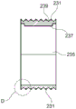
figures 1a to 1e are schematic cross-sectional views of one embodiment of an aerosol-generating article showing a substantially non-combustible wrapper applied to an aerosol-forming substrate;
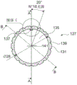
figure 2 is a schematic cross-sectional view of an embodiment of an aerosol-generating article for use with an aerosol-generating device comprising a heating element;
figure 3 is a schematic cross-sectional view of an embodiment of an aerosol-generating article comprising an integral heating element;
FIG. 4 is a schematic view of an embodiment of a pair of rollers (roll and pair of rolls) forming part of an apparatus according to the invention;
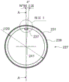
FIG. 5 is a web of substantially non-combustible wrapper material having a textured profile formed by the pair of rolls of FIG. 4;
fig. 6a and 6b show a profile portion of an embossing roll forming part of an embodiment of the apparatus according to the invention;
FIG. 7 is a cross-sectional view of the contoured portion of FIG. 6a taken along line A-A;
FIGS. 8a and 8b are exploded views of the outlined part of FIG. 7 taken in the area indicated as C;
FIG. 9 shows an end plan view of a contoured portion of the patterned roll forming part of another embodiment of an apparatus according to the present invention;
FIG. 10 shows the profile section of FIG. 9 in a perspective view;
FIG. 11a is a cross-sectional view of the contoured portion of FIG. 9 taken along line A-A;
FIG. 11B is a cross-sectional view of the contoured portion of FIG. 9 taken along line B-B;
FIG. 12a is an exploded view of the contoured portion of FIG. 11a taken in the area designated C;
FIG. 12b is an exploded view of the contoured portion of FIG. 11b taken in the area indicated as D;
FIG. 13 shows an end plan view of a contoured portion of an embossing roll forming part of yet another embodiment of an apparatus according to the present invention;
FIG. 14 shows an exploded view of the outlined part of FIG. 13 taken in the area indicated as B;
FIG. 15 shows the profile section of FIG. 13 in a perspective view;
FIG. 16 is a cross-sectional view of the contoured portion of FIG. 13 taken along line A-A;
FIG. 17 is an exploded view of the contoured portion of FIG. 16 taken in the area indicated as D;
FIG. 18 shows a top plan view of the contoured portion of FIG. 13; and is
Fig. 19 is an exploded view of the contoured portion of fig. 18 taken in the area designated C.
Wherever possible, the same numbers are used throughout the drawings to refer to the same features.
Detailed Description
Figures 1a to 1e show sequential packaging of an aerosol-forming substrate 20 with a substantially non-combustible wrapper 3. In the depicted embodiment, the substantially non-combustible wrapper is formed from two layers that are joined together by a lamination process to form wrapper 3. The outer layer was 45 grams per square meter (gsm)-1) Basis weight and a paper filter segment wrapper of 65 micrometers (μm) thickness. The inner layer was 17 grams per square meter (gsm)-1) Basis weight and 6.3 micrometer (mum) thickness of aluminum foil. The total thickness of the substantially non-combustible wrapper was 71.3 micrometers (μm). As shown in figure 1a, an aerosol-forming substrate 20 is delivered in direction a onto an open web of wrapper material on a conveyor or garniture 13. The web of wrapper material 3 is delivered from a pair of rolls (not shown) where the embossing roll has caused the inside of the wrapper to rollThe surface is textured to form embossed portions 5. The embossed portion 5 extends partially across the transverse width of the wrapper 3. The longitudinal dimension of wrapper 3 is perpendicular to the plane of the figure. In fig. 1B, one edge of the substantially non-combustible wrapper is folded onto the aerosol-forming substrate 20 in direction B. In figure 1c, adhesive is applied by an adhesive applicator 11 to the embossed portions 5 on the inner surface of the opposite edges of the substantially non-combustible wrapper 3. The embossed portion 5 is folded in direction C onto a portion 4 of the outer paper surface of the substantially non-combustible wrapper 3 in figure 1 d. Now the embossed portion 5 of the inner surface of the aluminium foil layer is in contact with the paper outer portion 4 of the substantially non-combustible wrapper 3.
As shown in fig. 1e, vertical pressure is applied directly on the substantially non-combustible wrapper 3 in direction D to ensure adhesion between the embossed portion 5 of the aluminium foil layer and the paper layer portion 4 of the substantially non-combustible wrapper 3. The embossed portion 5 ensures that the non-porous aluminium foil has a sufficient surface area for successful bonding of the aluminium foil and the paper exterior of the substantially non-combustible wrapper 3 in the region of the lap seam between the wrapper portions 5 and 4. Without the embossed portion 5, the metal aluminium foil layer of the essentially non-combustible wrapper 3, which is the inner surface that is glued and then pressed against the outer surface of the paper, is not porous, thereby creating problems in the gluing of the wrapper material. In such an arrangement, the aluminium layer of the wrapper is not sufficiently porous to absorb the glue, thus creating a weak glue line on the aerosol-generating article exiting the tobacco crimper. The performance of the formed crimpers and combiners for handling aerosol-generating articles may be reduced due to the weaker glue seam between the aluminum metal foil layer and the paper layer of the package. For example, both the combiner and crimper may experience increased down time and waste to remove defective products, resulting in potentially large losses. The substantially non-combustible wrapper 3 of the present invention mitigates losses that may be incurred in products having weak glue lines in the wrapper.
As shown in figure 1e, the aerosol-forming substrate 20 is packaged in a substantially non-combustible wrapper 3 formed from a thermally conductive layer of metal and an outer layer of paper filter segment wrapper in contact with the aerosol-forming substrate 20. The layers may be bonded together during the lamination process to form a substantially non-combustible wrapper 3.
The aluminium inner layer is the inner layer in contact with the aerosol-forming substrate 20. This layer has a heat conducting function. Alternatively or additionally, the aluminum inner layer may prevent the product from glowing when extended over the integral heat source.
The outer layer of the substantially non-combustible wrapper 3 is made of paper. Since the layer is located on the outside, it is important that the visual appearance and the qualitative appearance of the layer have to have a high standard. The local thickness of the embossment of the inner layer of the substantially non-combustible wrapper 3 means that the appearance of the outer layer of paper is not altered by the embossment pattern.
Figure 2 shows an aerosol-generating article 10 according to an embodiment of the present invention. The aerosol-generating article 10 comprises four elements arranged in coaxial alignment: an aerosol-forming substrate 20, a support element 30, an aerosol-cooling element 40 and a mouthpiece 50. These four elements are arranged in sequence and surrounded by an outer wrapper 60 to form the aerosol-generating article 10. The aerosol-generating article 10 has a proximal or mouth end 70 into which a user inserts during use into his or her mouth, and a distal end 80 located at the end of the aerosol-generating article 10 opposite the mouth end 70.
In use, air is drawn through the aerosol-generating article from the distal end 80 to the mouth end 70 by a user. The distal end 80 of the aerosol-generating article may also be described as the upstream end of the aerosol-generating article 10, and the mouth end 70 of the aerosol-generating article 10 may also be described as the downstream end of the aerosol-generating article 10. The elements of the aerosol-generating article 10 positioned between the mouth end 70 and the distal end 80 may be described as being upstream of the mouth end 70, or alternatively downstream of the distal end 80.
The aerosol-forming substrate 20 is positioned at the very distal or upstream end of the aerosol-generating article 10. In the embodiment shown in figure 2, the aerosol-forming substrate 20 comprises a gathered sheet of crimped homogenised tobacco material surrounded by a substantially non-combustible wrapper 3. A crimped sheet of homogenised tobacco material comprises glycerin as an aerosol former. The substantially non-combustible wrapper 3 is formed from a laminated filter segment wrapper having an outer layer of paper and an inner layer of aluminium. The inner layer of aluminum is embossed (textured) over a portion of its transverse width to provide an embossed area of the inner layer that will overlap a portion of the outer layer of paper when the substantially non-combustible wrapper 3 is wrapped around the aerosol-forming substrate 20. The aluminum inner layer is impermeable to the applied adhesive. By texturing the inner surface of the aluminum inner layer, the adhesion of the inner layer to the outer layer of paper is increased. This increased adhesive force prevents the lap seam between the edges of the substantially non-combustible wrapper 3 from opening or partially opening during assembly of the aerosol-generating article 10.
The support element 30 is located immediately downstream of the aerosol-forming substrate 20 and abuts the aerosol-forming substrate 20. In the embodiment shown in fig. 2, the support element is a hollow cellulose acetate tube. The support element 30 positions the aerosol-forming substrate 20 at the distal extremity 80 of the aerosol-generating article 10 such that it is penetrable by a heating element of the aerosol-generating device. The support element 30 serves to prevent the aerosol-forming substrate 20 from being pushed downstream within the aerosol-generating article 10 towards the aerosol-cooling element 40 when a heating element of an aerosol-generating device is inserted into the aerosol-forming substrate 20. The support element 30 also acts as a spacer to space the aerosol-cooling element 40 of the aerosol-generating article 10 from the aerosol-forming substrate 20.
The aerosol-cooling element 40 is located immediately downstream of the support element 30 and abuts the support element 30. In use, volatile material released from the aerosol-forming substrate 20 passes along the aerosol-cooling element 40 towards the mouth end 70 of the aerosol-generating article 10. The volatile material can be cooled within the aerosol-cooling element 40 to form an aerosol for inhalation by a user. In the embodiment illustrated in fig. 2, the aerosol-cooling element comprises a rolled and gathered polylactic acid sheet surrounded by a wrapper 90. The crimped and gathered polylactic acid sheet defines a plurality of longitudinal channels extending along the length of the aerosol-cooling element 40.
The mouthpiece 50 is positioned immediately downstream of the aerosol-cooling element 40 and against the aerosol-cooling element 40. In the embodiment illustrated in figure 2, the mouthpiece 50 comprises a conventional low filtration efficiency cellulose acetate tow filter.
To assemble the aerosol-generating article 10, the aerosol-forming substrate 20 may first be packaged in a substantially non-combustible wrapper 3 according to the steps shown in figure 1. The four elements described above (including the wrapped aerosol-forming substrate 20) are then aligned and tightly packed within the outer wrapper 60. In the embodiment shown in figure 2, the outer wrapper is a conventional cigarette paper. As shown in fig. 2, an optional row of perforations is provided in the region of the outer wrapper 60 surrounding the support element 30 of the aerosol-generating article 10.
In the embodiment illustrated in fig. 2, the distal end of the outer wrapper 60 of the aerosol-generating article 10 is surrounded by a spliced paper strap (not shown).
The aerosol-generating article 10 illustrated in figure 2 is designed to engage with an aerosol-generating device comprising a heating element for drawing or consumption by a user. In use, the heating element of the aerosol-generating device heats the aerosol-forming substrate 20 of the aerosol-generating article 10 to a sufficient temperature to form an aerosol which is drawn downstream through the aerosol-generating article 10 and inhaled by a user.
Figure 3 shows an aerosol-generating article 100 according to an embodiment of the present invention. The aerosol-generating article 100 comprises five elements arranged in coaxial alignment: an integrated heat source 25, an aerosol-forming substrate 20, a support element 30, an aerosol-cooling element 40 and a mouthpiece 50. These five elements are arranged in sequence and surrounded by an outer wrapper 60 to form the aerosol-generating article 10. The aerosol-generating article 100 shown in figure 3 differs from the aerosol-generating article 10 of figure 2 in that it comprises an integral heat source 25 at the distal end of the aerosol-forming substrate 20, and the integral heat source abuts the aerosol-forming substrate 20. In this embodiment, the substantially non-combustible wrapper 3 surrounds the entire length of the aerosol-forming substrate 20 and the integral heat source 25. By covering the integral heat source 25 as a carbon heat source 25, the substantially non-combustible wrapper 3 prevents the integral heat source from glowing. It may be necessary to partially remove package 3 from heat source 25 prior to ignition or activation.
The aerosol-generating article 100 shown in figure 3 is designed to enable a user to ignite the integral heat source 25 in order for the article to be smoked or consumed by the user. In use, the integrated heat source 25 heats the aerosol-forming substrate 20 of the aerosol-generating article 100 to a sufficient temperature to form an aerosol, which is drawn downstream through the aerosol-generating article 100 and inhaled by a user.
Figure 4 shows a pair of rollers (roller and counter-roller) forming part of an apparatus according to the invention. The counter roll comprises an embossing roll 27 having an embossing surface portion 26 and a smooth surface portion 28. Only a portion of the surface of the embossing roll comprises embossing teeth 31. In use, the embossing roll 27 will contact the inner aluminium foil layer (not shown) of the wrapper material and the embossed surface portion 26 comprising the teeth 31 covers the area of the inner layer of the substantially non-combustible wrapper which will overlap the outer surface of the wrapper material when the adhesive is applied and the two portions overlap as shown in figures 1a to 1 e. The counter roll, i.e. the smooth surface roll 29, will be in contact with the outer layer of the wrapper material. Smooth surface roller 29 ensures that the outer layer of the substantially non-flammable wrapper is not altered by the embossing process.
Each of the pair of rollers 27, 29 is mounted to a shaft 33a, 33b which may be mounted to a crimper (not shown) downstream of an aerosol-forming substrate crimping machine (not shown). The shafts 33a, 33b of the rollers may be freely movable or motorized. The roller is easy to mount if the shaft can move freely.
A ring screw (not shown) may be provided which is operated by the operator using a handle and allows the distance between the embossing roller 27 and the smooth-surface roller 29 to be adjusted. Adjusting the distance between the surfaces of rollers 27, 29 may vary the depth of embossing on the inner surface of substantially non-combustible wrapper 3 passing between rollers 27, 29.
Figure 5 shows the inner surface of the web of substantially non-combustible packages 3 after treatment by the pair of rollers of figure 4. The embossed portion 5 extends along the entire length of the web and partially across the transverse width of the web of the substantially non-combustible wrapper. The smooth portion 2 of the inner surface of the web of substantially non-combustible wrapper 3 remains smooth. In this way, when the wrapper 3 surrounds the rod of aerosol-forming substrate, a smooth portion of the inner surface of the substantially non-combustible wrapper 3 will come into intimate contact with the rod of aerosol-forming substrate.
Fig. 6a to 8b depict the profile portion of an embossing roller forming part of an apparatus according to the invention. Fig. 9 to 12b depict an alternative profile portion of an embossing roll forming part of an apparatus according to the invention. Fig. 13 to 19 depict another alternative profile portion of an embossing roll forming part of an apparatus according to the present invention. Like features in each embodiment of the patterned roll are denoted by like reference numerals, increased by a factor of 100.
Fig. 6a is an end plan view of the contoured portion 26 of the embossing roll 27. Fig. 6b is a perspective view of the contoured portion 26. Referring to fig. 6a, the surface of the profiled section 26 comprises a plurality of teeth 31, adjacent teeth 31 being separated by recesses 39 around the entire circumference of the embossing roll 27. 45 teeth are arranged around the circumference of the embossing roller 27, each tooth occupying a circumferential angle of 8 degrees measured from the longitudinal axis of the roller 27 including the centre point 41 of the hollow core 35 of the embossing roller. The diameter of the embossing roll 27 to the tip of the teeth was measured to be 30 mm. The diameter of the emboss roller 27 to the bottom of the recess 39 was measured to be 28 mm. In the embodiment depicted in fig. 6a to 8, the height of the tooth 31 from the base of the adjacent recess 39 to the tip of the tooth 31 is 2 mm.
Fig. 6b shows the profile portion 26 of the tooth shown in fig. 6a, which extends transversely across the width of the profile portion 26. It should be understood that only the contoured portion 26 of the patterned roll is shown in this embodiment and the smooth surface of the remaining transverse width of the patterned roll 27 is not shown. The hollow core 35 allows the embossing roller 27 to be fitted onto the shaft (see 33a, 33b in fig. 4) and the positioning flange 37 ensures that the shaft and the roller 27 rotate together.
Fig. 7 is a cross-sectional view of the contoured portion 26 of the patterned roll 27 of fig. 6a, taken along line a-a. The hollow core 35 has a diameter of 26 mm (excluding the positioning flange 37). The teeth 31 and adjacent recesses 39 extend across the width of the profile section 26.
Fig. 8a and 8b are exploded views of the outlined part of fig. 7 taken in the area indicated as C. The first and second surfaces 41, 43 of each tooth 31 join at the base of the recess 39. In the depicted embodiment, the first face 41 of a first tooth 31a and the second face 43 of an adjacent second tooth 31b are at an angle α of 90 degrees to each other.
Fig. 9 shows an end plan view of a contoured portion 126 of an embossing roll 127 forming part of the apparatus according to the invention. Fig. 9 is an end plan view of the contoured portion 126 of the patterned roll 127. Fig. 10 is a perspective view of the contoured portion 126. Referring to fig. 9, the surface of the contoured portion 126 includes a plurality of teeth 131, with adjacent teeth 131 separated by recesses 139 around the entire circumference of the patterned roll 127. Each tooth 131 has a flat tip (end). The 18 teeth 131 are arranged around the circumference of the patterned roll 127, each tooth occupying a circumferential angle of 20 degrees measured from the longitudinal axis of the roll 127 including the center point 141 of the hollow core 135 of the patterned roll. The diameter of the patterned roll 127 to the flat tip of the teeth was measured to be 30 millimeters. The diameter of the emboss roller 127 to the bottom of the recess 139 was measured to be 28 mm. In the embodiment depicted in fig. 9-12 b, the height of the tooth 131 from the base of the adjacent recess 139 to the flat tip of the tooth 131 is 2 millimeters.
Fig. 10 shows the profile portion 126 of the tooth shown in fig. 9, which extends transversely across the width of the profile portion 126. It should be understood that only the contoured portion 126 of the patterned roll is shown in this embodiment and the smooth surface of the remaining transverse width of the patterned roll 127 is not shown. The hollow core 135 allows the embossing roller 127 to be fitted onto the shaft (see 33a, 33b in fig. 4) and the positioning flange 137 ensures that the shaft and the roller 27 rotate together.
Fig. 11a is a cross-sectional view of the contoured portion 126 of the patterned roll 127 of fig. 9 taken along line a-a, and fig. 11B is a cross-sectional view of the contoured portion 126 of the patterned roll 127 of fig. 9 taken along line B-B. The hollow core 135 has a diameter of 26 mm (excluding the positioning flange 137). The teeth 131 and adjacent recesses 139 extend across the width of the profile portion 126.
Fig. 12a is an exploded view of the outlined part of fig. 11a taken in the area indicated as C. The first and second faces 141, 143 of each tooth 131 engage at the base of the recess 139. As shown in fig. 12b, which is an exploded view of the contoured portion of fig. 11b taken in the area designated D, in the depicted embodiment, the first face 141 of a first tooth 131a and the second face 143 of an adjacent second tooth 131b are at an angle β of 90 degrees to each other.
Fig. 13 shows an end plan view of a contoured portion 226 of an embossing roll 227 forming part of yet another embodiment of an apparatus according to the present invention.
Fig. 13 is an end plan view of the contoured portion 226 of the patterned roll 227. The surface of the contoured portion 226 includes a plurality of teeth 231, with adjacent teeth 231 separated by a recess 239 around the entire circumference of the patterned roll 227. As best shown in fig. 19, the tip of each tooth 231 is offset from the longitudinal axis of the contoured portion 226, which includes the center point 241. In the depicted embodiment, the offset angle γ is 45 degrees. In this manner, the tip of each tooth 231 has both a transverse dimension and a circumferential dimension. Fig. 19 also depicts rows of teeth extending across the lateral width of the contoured portion 226. The rows of teeth 2310, 2311, 2312, 2313, 2314, 2315, 2316, 2317 have a dimension of 3 millimeters as measured along the end of each tooth 231. The tips of the teeth 231 in each adjacent row are at an angle α' of 90 degrees to each other.
Fig. 13 shows 90 teeth 231 arranged in rows around the circumference of the embossing roller 227, each tooth occupying a circumferential angle of 4 degrees measured from the longitudinal axis of the roller 227 including the center point 241 of the hollow core 235 of the embossing roller. The diameter of the embossing roll 227 to the tip of the teeth was measured to be 30 mm. The diameter of the embossing roller 227 to the bottom of the recess 239 was measured to be 29 mm. In the embodiment depicted in fig. 13-19, the height of the tooth 231 from the base of the adjacent recess 239 to the tip of the tooth 231 is 1 millimeter.
Fig. 15 shows the profile portion 226 including a row 231 of teeth extending transversely across the width of the profile portion 226. It should be understood that only the contoured portion 226 of the patterned roll is shown in this embodiment, and the smooth surface of the remaining transverse width of the patterned roll 227 is not shown. The hollow core 235 allows the embossing roller 227 to be fitted to a shaft (see 33a, 33b in fig. 4), and the locating flange 237 shown in fig. 16 ensures that the shaft and roller 227 rotate together.
Fig. 16 is a cross-sectional view of the contoured portion 226 of the patterned roll 227 of fig. 13 taken along line a-a. The hollow core 235 has a diameter of 26 mm (excluding the locating flange 237). The teeth 231 and adjacent recesses 239 extend across the width of the profile portion 226.
Fig. 17 is an exploded view of the contoured portion 226 of fig. 16 taken in the area designated D. The first face 241 and the second face 243 of each tooth 231 join at the base of the recess 239. In the depicted embodiment, the first face 243 of a first tooth 231a and the second face 241 of an adjacent second tooth 231b are at an angle δ of 90 degrees to each other.
Fig. 14 is an exploded view taken at area B in fig. 13. The contoured portion 226 includes rows of teeth 2310 and 2311, the tips of which are disposed at a 90 degree angle to each other.
The faces 241 and 243 of adjacent teeth that together form the recess 239 are at an angle δ to each other.
It can be seen that a variety of tooth profiles are contemplated. The height of each tine is less than the thickness of the inner conductive layer of the substantially non-combustible wrapper. In this manner, the embossing roll can texture the inner surface of the substantially non-flammable wrapper without affecting the outer surface of the substantially non-flammable wrapper. The embossed surface does not penetrate or otherwise penetrate through the entire thickness of the substantially non-combustible wrapper. In this manner, the embossed surface provides a textured surface portion on the inner layer of the substantially non-combustible wrapper to improve adhesion between overlapping layers of the substantially non-combustible wrapper without affecting the quality or appearance of the outer layer.
The height of the teeth on the patterned roll may be 1 millimeter or greater. A relatively large height dimension of the teeth is possible because the outer layer of the essentially non-combustible wrapper is fixed against the smooth surface of the counter roller and, since the distance between the rollers is adjustable, the depth of the embossing can be adjusted accordingly without affecting the quality or appearance of the outer layer, regardless of the size of the teeth.
The various embossing rollers with different tooth profiles have a hollow core of the same diameter (about 8 mm to about 36 mm, preferably 26 mm) so that they can be easily and quickly mounted on the same shaft that can be fixed to the crimper. A cotter pin may be used to secure the roller to the shaft to prevent rotation of the roller relative to the shaft.
In the manufacture of the aerosol-forming article of the invention, the substantially non-combustible wrapper material may be closed around the aerosol-forming substrate and the overlapping edges adhered to one another using an adhesive (e.g. glue). The gluing process may be part of a larger process involving crimping of the aerosol-forming substrate (by a "crimper", not shown) which inputs the aerosol-forming substrate and the substantially non-combustible wrapper material onto a conveyor (13 in figures 1a to 1 e) and outputs a rod of the wrapped aerosol-forming substrate. The rod of packaged aerosol-forming substrate is then used in a "combiner" which bonds the filter and other components to the rod of packaged aerosol-forming substrate to form the final product.
The manufacturing process can be carried out in the following way: the substantially non-combustible wrapper is folded about the longitudinal axis of the rod of the aerosol-forming substrate, seam glue is then applied along one edge of the inner surface of the inner layer of the substantially non-combustible wrapper (e.g. the surface in contact with the aerosol-forming substrate), and the glued area is then pressed against the top surface of the other edge of the substantially non-combustible wrapper.
For example, using a pair of rollers as shown in figure 4, the inner layer of the substantially non-combustible wrapper (i.e. the layer which is in contact with the aerosol-forming substrate and which overlaps the outer layer of the substantially non-combustible wrapper after the gluing process) is embossed to form a rough profile of the inner surface of the inner layer of the substantially non-combustible wrapper. The embossing increases the contact area of the surface of the inner layer of the substantially non-combustible wrapper in the region overlapping the outer surface of the outer layer. This provides better bonding of the substantially non-flammable wrapper at the seam.
During packaging of the aerosol-forming substrate in the substantially non-combustible wrapper, the web of substantially non-combustible wrapper material may be pulled between a pair of rollers by a crimper. The axes of the embossing roll and smooth surface roll of the pair of rolls may be oriented orthogonal to the direction of travel of the substantially non-combustible web of wrapper material.
The contoured portion of the patterned roll forms a textured portion in an area on the inner layer of the substantially non-combustible wrapper that will overlap the outer layer when the wrapper is closed around the aerosol-forming substrate, but does not necessarily cover all of the inner layer surface. In this way, the smooth inner surface of the inner layer may be in intimate contact with the aerosol-forming substrate.
The height of the teeth on the embossing roll is such that the appearance of the outer layer is not altered by the embossing process. Alternatively or additionally, the distance between the embossing roll and the smooth surface roll is such that the appearance of the outer layer is not altered by the embossing process.
Due to the improved adhesion of the embossed non-porous (e.g. metal) portion of the inner layer to the smooth outer layer of the substantially non-combustible wrapper, the quality of the rod of the wrapper aerosol-forming substrate may be improved and the number of discarded or rejected products may be reduced.
Throughout the detailed description and claims of this specification, the words "comprise" and "comprise", and variations thereof, mean "including but not limited to", and are not intended to (and do not) exclude other moieties, additives, components, integers or steps. Throughout the description and claims of this specification, the singular encompasses the plural unless the context otherwise requires. In particular, where the indefinite article is used, the specification is to be understood as contemplating plurality as well as singularity, unless the context requires otherwise.
Features, integers, characteristics, compounds, chemical moieties or groups described in conjunction with a particular aspect, embodiment or example of the invention are to be understood to be applicable to any other aspect, embodiment or example described herein unless incompatible therewith. All of the features disclosed in this specification (including any accompanying claims, abstract and drawings), and/or all of the steps of any method or process so disclosed, may be combined in any combination, except combinations where at least some of such features and/or steps are mutually exclusive. The invention is not limited to the details of any of the foregoing embodiments. The invention extends to any novel one, or any novel combination, of the features disclosed in this specification (including any accompanying claims, abstract and drawings), or to any novel one, or any novel combination, of the steps of any method or process so disclosed.
Claims (15)
1. An aerosol-generating article for use with an aerosol-generating device comprising a heating element, the aerosol-generating article comprising:
an aerosol-forming substrate;
a substantially non-combustible wrapper surrounding the aerosol-forming substrate and comprising an inner surface and an outer surface;
wherein the inner surface of the wrapper has an at least partially textured surface configured to overlap a portion of the outer surface of the wrapper when the wrapper is wrapped around the aerosol-forming substrate.
2. An aerosol-generating article comprising
An aerosol-forming substrate comprising one or more of tobacco and a nicotine source;
a heating element at an upstream end of the aerosol-forming substrate and arranged to heat the aerosol-forming substrate so as to form an aerosol when actuated;
a substantially non-combustible wrapper surrounding the aerosol-forming substrate and at least a portion of the heating element, the wrapper comprising an inner surface and an outer surface;
wherein the inner surface of the wrapper has an at least partially textured surface configured to overlap a portion of the outer surface of the wrapper when the wrapper is wrapped around the aerosol-forming substrate.
3. An aerosol-generating article according to claim 1 or 2, wherein the at least partially textured surface is embossed.
4. An aerosol-generating article according to any one of claims 1 to 3, wherein the at least partially textured surface extends partially around the circumference of the aerosol-forming substrate.
5. An aerosol-generating article according to any one of claims 1 to 4, wherein the textured portion has a width of between about 10 millimeters and about 20 millimeters.
6. An aerosol-generating article according to any one of claims 1 to 4, wherein the textured surface has a width of between 0.5 mm to 10 mm; or between 1 mm and 8 mm; or between 1 mm and 6 mm; or between 1 mm and 5 mm; or between 2 mm and 5 mm.
7. An aerosol-generating article according to any one of claims 1 to 6, wherein at least the inner surface of the wrapper is metallic.
8. An aerosol-generating article according to claim 7, wherein the textured portion of the metal inner surface is bonded to the outer surface of the opposing edge of the wrapper.
9. An aerosol-generating article according to any one of claims 1 to 8, wherein the wrapper comprises two layers: being the innermost layer of a package according to any one of claims 1 to 8 and an outer layer surrounding the innermost layer.
10. An aerosol-generating article according to any of claims 1 to 9, wherein the wrapper extends over at least a portion of the length of the aerosol-forming substrate.
11. An aerosol-generating article according to any one of claims 1 to 10, wherein the aerosol-forming substrate comprises tobacco.
12. An aerosol-generating article according to any of claims 1 to 11, wherein the aerosol-forming substrate comprises a nicotine source.
13. An apparatus for forming an embossed wrapper for surrounding an aerosol-forming substrate, the apparatus comprising a pair of nip rollers, one roller of the pair of nip rollers being an embossing roller, the embossing roller comprising a contoured surface for forming an embossed pattern, and the other roller of the pair of nip rollers being a smooth-surfaced roller, the pair of rollers being configured (adapted, arranged) to receive a substantially non-combustible wrapper material web between the embossing roller and the smooth-surfaced roller, the embossing roller being configured to form a textured pattern in a portion of the width of the substantially non-combustible wrapper material web as the substantially non-combustible wrapper material web passes between the pair of rollers.
14. A method of forming an embossed wrapper for enclosing an aerosol-forming substrate of a heated smoking article, the method comprising: passing a web of substantially non-combustible wrapper material through a pair of nip rollers, one of the pair of nip rollers being an embossing roller comprising a contoured surface across a transverse portion of its surface, the other of the pair of nip rollers being a smooth-surfaced roller; deforming one side of the web of non-combustible material across a portion of its width to form a textured surface; positioning an aerosol-forming substrate on a side of a non-combustible material comprising the textured surface; and packaging the non-combustible material web material around the aerosol-forming substrate and bonding the textured surface of the non-combustible material web to an outer smooth surface of the non-combustible material web.
15. A method of forming an aerosol-generating article, the method comprising: embossing the inner surface of the substantially non-combustible wrapper; a rod forming an aerosol-forming substrate on the embossed wrapper; surrounding the aerosol-forming substrate with the embossed wrapper; applying adhesive to a portion of the embossed inner surface that overlaps a portion of the outer surface of the wrapper; closing the wrapper around the aerosol-forming substrate by adhering the overlapping portion of the embossed inner surface to the outer surface of the wrapper.
Applications Claiming Priority (3)
| Application Number | Priority Date | Filing Date | Title |
|---|---|---|---|
| EP18180249 | 2018-06-27 | ||
| EP18180249.7 | 2018-06-27 | ||
| PCT/EP2019/066548 WO2020002165A1 (en) | 2018-06-27 | 2019-06-21 | Aerosol-generating article and apparatus for forming an aerosol-generating article |
Publications (2)
| Publication Number | Publication Date |
|---|---|
| CN112218548A true CN112218548A (en) | 2021-01-12 |
| CN112218548B CN112218548B (en) | 2023-04-04 |
Family
ID=62814919
Family Applications (1)
| Application Number | Title | Priority Date | Filing Date |
|---|---|---|---|
| CN201980037941.3A Active CN112218548B (en) | 2018-06-27 | 2019-06-21 | Aerosol-generating article and apparatus for forming an aerosol-generating article |
Country Status (9)
| Country | Link |
|---|---|
| US (1) | US12114690B2 (en) |
| EP (1) | EP3813572B1 (en) |
| JP (1) | JP7344228B2 (en) |
| KR (1) | KR102841359B1 (en) |
| CN (1) | CN112218548B (en) |
| ES (1) | ES3034782T3 (en) |
| MX (1) | MX2020013333A (en) |
| PL (1) | PL3813572T3 (en) |
| WO (1) | WO2020002165A1 (en) |
Cited By (1)
| Publication number | Priority date | Publication date | Assignee | Title |
|---|---|---|---|---|
| CN117295413A (en) * | 2021-12-29 | 2023-12-26 | 韩国烟草人参公社 | Media segments, aerosol-generating articles and systems including the same |
Families Citing this family (19)
| Publication number | Priority date | Publication date | Assignee | Title |
|---|---|---|---|---|
| GB202009165D0 (en) * | 2020-06-16 | 2020-07-29 | Nicoventures Trading Ltd | Article for use in a non-combustile aerosol provision system |
| GB202009163D0 (en) * | 2020-06-16 | 2020-07-29 | Nicoventures Trading Ltd | Article for use in non-combustible aerosol provision system |
| JPWO2022102049A1 (en) | 2020-11-12 | 2022-05-19 | ||
| EP4245158A1 (en) | 2020-11-12 | 2023-09-20 | Japan Tobacco Inc. | Flavor generating article |
| WO2022102046A1 (en) | 2020-11-12 | 2022-05-19 | 日本たばこ産業株式会社 | Flavor-generating article |
| WO2022112576A1 (en) * | 2020-11-27 | 2022-06-02 | Philip Morris Products S.A. | Aerosol-generating article having wrapper comprising an embossed portion |
| EP4250966B1 (en) * | 2020-11-27 | 2026-04-01 | Philip Morris Products S.A. | Aerosol-generating article having a wrapper |
| WO2022112575A1 (en) * | 2020-11-27 | 2022-06-02 | Philip Morris Products S.A. | Aerosol-generating article comprising a wrapper |
| US20240365846A1 (en) * | 2021-04-12 | 2024-11-07 | Philip Morris Products S.A. | Aerosol-generating article comprising a dual-layer wrapping structure |
| BR112023020951A2 (en) * | 2021-04-12 | 2023-12-12 | Philip Morris Products Sa | AEROSOL GENERATING ARTICLE COMPRISING AN ENCLOSURE WITH AN OVERLAPPING REGION |
| WO2022224435A1 (en) * | 2021-04-23 | 2022-10-27 | 日本たばこ産業株式会社 | Method for producing cartridge for flavor inhaler |
| KR102854664B1 (en) * | 2021-10-29 | 2025-09-03 | 주식회사 케이티앤지 | Cigarette and device for generating aerosol with the same |
| WO2023089803A1 (en) | 2021-11-22 | 2023-05-25 | 日本たばこ産業株式会社 | Flavor-generating substance and smoking system |
| US20250031749A1 (en) * | 2021-11-29 | 2025-01-30 | Philip Morris Products S.A. | Aerosol-generating article having wrapper comprising an adhesive |
| EP4616736A1 (en) | 2022-11-11 | 2025-09-17 | Japan Tobacco Inc. | Flavor-generating article and flavor inhalation system |
| KR20250088583A (en) | 2022-11-11 | 2025-06-17 | 니뽄 다바코 산교 가부시키가이샤 | Flavor producing article |
| KR20250122499A (en) | 2022-12-26 | 2025-08-13 | 니뽄 다바코 산교 가부시키가이샤 | Flavor inhalation system |
| EP4648627A1 (en) | 2023-01-12 | 2025-11-19 | N2B Limited | Smoking capsule with resistive heating element |
| DE102023132802A1 (en) * | 2023-11-24 | 2025-05-28 | Marcel P. HOFSAESS | Shrink cap and method for producing a shrink cap |
Citations (6)
| Publication number | Priority date | Publication date | Assignee | Title |
|---|---|---|---|---|
| US2890704A (en) * | 1954-11-10 | 1959-06-16 | William R Lamm | Cigarette |
| CN1474660A (en) * | 2000-09-18 | 2004-02-11 | �ָ��š���ɭ������˹����˾ | Low sidestream cigarettes with non-combustible treatments |
| US20050172976A1 (en) * | 2002-10-31 | 2005-08-11 | Newman Deborah J. | Electrically heated cigarette including controlled-release flavoring |
| CN103929989A (en) * | 2011-09-20 | 2014-07-16 | R.J.雷诺兹烟草公司 | Segmented smoking article with substrate cavity |
| WO2015082648A1 (en) * | 2013-12-05 | 2015-06-11 | Philip Morris Products S.A. | Heated aerosol generating article with thermal spreading wrap |
| WO2018037048A1 (en) * | 2016-08-26 | 2018-03-01 | Philip Morris Products S.A. | Aerosol-generating article comprising an aerosol-forming substrate and a heat-conducting element |
Family Cites Families (16)
| Publication number | Priority date | Publication date | Assignee | Title |
|---|---|---|---|---|
| US4955397A (en) * | 1989-07-10 | 1990-09-11 | Brown & Williamson Tobacco Corporation | Cigarette |
| KR100728489B1 (en) * | 2005-11-24 | 2007-06-14 | 박신택 | Tabacco have incombustible sheet |
| MX2012010754A (en) | 2010-03-22 | 2013-02-27 | British American Tobacco Co | Lip smoking article wrapper, smoking article, method and apparatus. |
| JP2011205916A (en) * | 2010-03-29 | 2011-10-20 | British American Tobacco (Investments) Ltd | Smoking article and method of manufacturing smoking article |
| GB2479775A (en) * | 2010-04-22 | 2011-10-26 | British American Tobacco Co | Embossing smoking article wrappers |
| CA2837953C (en) | 2011-05-31 | 2020-06-16 | Philip Morris Products S.A. | Rods for use in smoking articles |
| EP2731717A1 (en) | 2011-07-12 | 2014-05-21 | Dow Corning Corporation | Lanthanide complexes with imidazole ligands for condensation reactions |
| AT512347B1 (en) | 2011-12-23 | 2013-09-15 | Tannpapier Gmbh | AS A FILM TRAINED MOUTHPIECE OF A FILTER CIGARETTE |
| TW201438607A (en) * | 2012-10-16 | 2014-10-16 | British American Tobacco Co | Smoking article wrapper and method of making a smoking article |
| PL2961286T3 (en) * | 2013-02-27 | 2018-01-31 | Philip Morris Products Sa | Smoking article having hidden indicia |
| WO2015007556A1 (en) | 2013-07-18 | 2015-01-22 | Philip Morris Products S.A. | Method of manufacturing an airflow directing segment for a smoking article |
| UA118857C2 (en) | 2013-12-05 | 2019-03-25 | Філіп Морріс Продактс С.А. | Thermal laminate rods for use in aerosol-generating articles |
| KR20170133329A (en) | 2015-03-31 | 2017-12-05 | 필립모리스 프로덕츠 에스.에이. | A smoking article comprising a wrapper having a plurality of projections provided on an inner surface |
| US20170055581A1 (en) | 2015-08-31 | 2017-03-02 | British American Tobacco (Investments) Limited | Article for use with apparatus for heating smokable material |
| DE102015118595A1 (en) * | 2015-10-30 | 2017-06-01 | Axagarius Gmbh & Co. Kg | Marked filter paper for use as a test substrate in the case of standardized methods for assessing the ignition tendency of cigarettes |
| JP7018925B2 (en) | 2016-07-07 | 2022-02-14 | ジェイティー インターナショナル エス.エイ. | Smoking products and their manufacturing methods |
-
2019
- 2019-06-21 KR KR1020207034989A patent/KR102841359B1/en active Active
- 2019-06-21 ES ES19732652T patent/ES3034782T3/en active Active
- 2019-06-21 WO PCT/EP2019/066548 patent/WO2020002165A1/en not_active Ceased
- 2019-06-21 CN CN201980037941.3A patent/CN112218548B/en active Active
- 2019-06-21 PL PL19732652.3T patent/PL3813572T3/en unknown
- 2019-06-21 US US17/251,357 patent/US12114690B2/en active Active
- 2019-06-21 EP EP19732652.3A patent/EP3813572B1/en active Active
- 2019-06-21 MX MX2020013333A patent/MX2020013333A/en unknown
- 2019-06-21 JP JP2020568762A patent/JP7344228B2/en active Active
Patent Citations (6)
| Publication number | Priority date | Publication date | Assignee | Title |
|---|---|---|---|---|
| US2890704A (en) * | 1954-11-10 | 1959-06-16 | William R Lamm | Cigarette |
| CN1474660A (en) * | 2000-09-18 | 2004-02-11 | �ָ��š���ɭ������˹����˾ | Low sidestream cigarettes with non-combustible treatments |
| US20050172976A1 (en) * | 2002-10-31 | 2005-08-11 | Newman Deborah J. | Electrically heated cigarette including controlled-release flavoring |
| CN103929989A (en) * | 2011-09-20 | 2014-07-16 | R.J.雷诺兹烟草公司 | Segmented smoking article with substrate cavity |
| WO2015082648A1 (en) * | 2013-12-05 | 2015-06-11 | Philip Morris Products S.A. | Heated aerosol generating article with thermal spreading wrap |
| WO2018037048A1 (en) * | 2016-08-26 | 2018-03-01 | Philip Morris Products S.A. | Aerosol-generating article comprising an aerosol-forming substrate and a heat-conducting element |
Cited By (1)
| Publication number | Priority date | Publication date | Assignee | Title |
|---|---|---|---|---|
| CN117295413A (en) * | 2021-12-29 | 2023-12-26 | 韩国烟草人参公社 | Media segments, aerosol-generating articles and systems including the same |
Also Published As
| Publication number | Publication date |
|---|---|
| US20210244079A1 (en) | 2021-08-12 |
| MX2020013333A (en) | 2021-03-09 |
| KR20210024455A (en) | 2021-03-05 |
| EP3813572B1 (en) | 2025-06-04 |
| ES3034782T3 (en) | 2025-08-22 |
| EP3813572A1 (en) | 2021-05-05 |
| EP3813572C0 (en) | 2025-06-04 |
| PL3813572T3 (en) | 2025-08-18 |
| WO2020002165A1 (en) | 2020-01-02 |
| BR112020024275A2 (en) | 2021-02-23 |
| CN112218548B (en) | 2023-04-04 |
| US12114690B2 (en) | 2024-10-15 |
| JP2021530200A (en) | 2021-11-11 |
| JP7344228B2 (en) | 2023-09-13 |
| KR102841359B1 (en) | 2025-08-01 |
Similar Documents
| Publication | Publication Date | Title |
|---|---|---|
| CN112218548B (en) | Aerosol-generating article and apparatus for forming an aerosol-generating article | |
| CN107072291B (en) | Method and apparatus for manufacturing a curled web | |
| EP3850956B1 (en) | Method for manufacturing aerosol-generation rod, and aerosol-generation article comprising aerosol-generation rod | |
| EP3076811B1 (en) | Heated aerosol generating article with thermal spreading endpiece | |
| TWI639393B (en) | Thermally conducting rods for use in aerosol-generating articles and method of forming the same | |
| KR102157508B1 (en) | Flavoured rods for use in aerosol-generating articles | |
| CN105722415B (en) | Non-tobacco nicotine-containing products | |
| KR102436108B1 (en) | Heated aerosol generating article with thermal spreading wrap | |
| CN105744850B (en) | Thermal lamination strips for aerosol-generating articles | |
| AU2018200641A1 (en) | Blended rods for use in aerosol-generating articles | |
| JP7595005B2 (en) | Tobacco rods for flavor inhalers | |
| RU2791707C2 (en) | Aerosol generating unit (versions), device and method for forming aerosol generating unit embossed wrap and method for forming aerosol generating unit | |
| BR112020024275B1 (en) | AEROSOL GENERATOR ARTICLE | |
| JP2023541117A (en) | Aerosol generating articles | |
| HK1223518B (en) | Heated aerosol generating article with thermal spreading endpiece |
Legal Events
| Date | Code | Title | Description |
|---|---|---|---|
| PB01 | Publication | ||
| PB01 | Publication | ||
| SE01 | Entry into force of request for substantive examination | ||
| SE01 | Entry into force of request for substantive examination | ||
| GR01 | Patent grant | ||
| GR01 | Patent grant |