JP7334682B2 - vehicle air conditioning system - Google Patents
vehicle air conditioning system Download PDFInfo
- Publication number
- JP7334682B2 JP7334682B2 JP2020102381A JP2020102381A JP7334682B2 JP 7334682 B2 JP7334682 B2 JP 7334682B2 JP 2020102381 A JP2020102381 A JP 2020102381A JP 2020102381 A JP2020102381 A JP 2020102381A JP 7334682 B2 JP7334682 B2 JP 7334682B2
- Authority
- JP
- Japan
- Prior art keywords
- evaporator
- equipment
- refrigerant
- air
- heat medium
- Prior art date
- Legal status (The legal status is an assumption and is not a legal conclusion. Google has not performed a legal analysis and makes no representation as to the accuracy of the status listed.)
- Active
Links
Images


Classifications
-
- B—PERFORMING OPERATIONS; TRANSPORTING
- B60—VEHICLES IN GENERAL
- B60H—ARRANGEMENTS OF HEATING, COOLING, VENTILATING OR OTHER AIR-TREATING DEVICES SPECIALLY ADAPTED FOR PASSENGER OR GOODS SPACES OF VEHICLES
- B60H1/00—Heating, cooling or ventilating devices
- B60H1/00357—Air-conditioning arrangements specially adapted for particular vehicles
- B60H1/00371—Air-conditioning arrangements specially adapted for particular vehicles for vehicles carrying large numbers of passengers, e.g. buses
-
- B—PERFORMING OPERATIONS; TRANSPORTING
- B60—VEHICLES IN GENERAL
- B60H—ARRANGEMENTS OF HEATING, COOLING, VENTILATING OR OTHER AIR-TREATING DEVICES SPECIALLY ADAPTED FOR PASSENGER OR GOODS SPACES OF VEHICLES
- B60H1/00—Heating, cooling or ventilating devices
- B60H1/00507—Details, e.g. mounting arrangements, desaeration devices
- B60H1/00592—Add-on devices, e.g. heat/cooling boxes, compartment dividers, upgrade sets
-
- B—PERFORMING OPERATIONS; TRANSPORTING
- B60—VEHICLES IN GENERAL
- B60H—ARRANGEMENTS OF HEATING, COOLING, VENTILATING OR OTHER AIR-TREATING DEVICES SPECIALLY ADAPTED FOR PASSENGER OR GOODS SPACES OF VEHICLES
- B60H1/00—Heating, cooling or ventilating devices
- B60H1/32—Cooling devices
- B60H1/3204—Cooling devices using compression
- B60H1/323—Cooling devices using compression characterised by comprising auxiliary or multiple systems, e.g. plurality of evaporators, or by involving auxiliary cooling devices
-
- B—PERFORMING OPERATIONS; TRANSPORTING
- B60—VEHICLES IN GENERAL
- B60K—ARRANGEMENT OR MOUNTING OF PROPULSION UNITS OR OF TRANSMISSIONS IN VEHICLES; ARRANGEMENT OR MOUNTING OF PLURAL DIVERSE PRIME-MOVERS IN VEHICLES; AUXILIARY DRIVES FOR VEHICLES; INSTRUMENTATION OR DASHBOARDS FOR VEHICLES; ARRANGEMENTS IN CONNECTION WITH COOLING, AIR INTAKE, GAS EXHAUST OR FUEL SUPPLY OF PROPULSION UNITS IN VEHICLES
- B60K11/00—Arrangement in connection with cooling of propulsion units
- B60K11/02—Arrangement in connection with cooling of propulsion units with liquid cooling
- B60K11/04—Arrangement or mounting of radiators, radiator shutters, or radiator blinds
-
- B—PERFORMING OPERATIONS; TRANSPORTING
- B60—VEHICLES IN GENERAL
- B60H—ARRANGEMENTS OF HEATING, COOLING, VENTILATING OR OTHER AIR-TREATING DEVICES SPECIALLY ADAPTED FOR PASSENGER OR GOODS SPACES OF VEHICLES
- B60H1/00—Heating, cooling or ventilating devices
- B60H1/00271—HVAC devices specially adapted for particular vehicle parts or components and being connected to the vehicle HVAC unit
- B60H1/00278—HVAC devices specially adapted for particular vehicle parts or components and being connected to the vehicle HVAC unit for the battery
-
- B—PERFORMING OPERATIONS; TRANSPORTING
- B60—VEHICLES IN GENERAL
- B60H—ARRANGEMENTS OF HEATING, COOLING, VENTILATING OR OTHER AIR-TREATING DEVICES SPECIALLY ADAPTED FOR PASSENGER OR GOODS SPACES OF VEHICLES
- B60H1/00—Heating, cooling or ventilating devices
- B60H1/00507—Details, e.g. mounting arrangements, desaeration devices
- B60H1/00557—Details of ducts or cables
- B60H1/00571—Details of ducts or cables of liquid ducts, e.g. for coolant liquids or refrigerants
-
- B—PERFORMING OPERATIONS; TRANSPORTING
- B60—VEHICLES IN GENERAL
- B60H—ARRANGEMENTS OF HEATING, COOLING, VENTILATING OR OTHER AIR-TREATING DEVICES SPECIALLY ADAPTED FOR PASSENGER OR GOODS SPACES OF VEHICLES
- B60H1/00—Heating, cooling or ventilating devices
- B60H1/00007—Combined heating, ventilating, or cooling devices
- B60H1/00207—Combined heating, ventilating, or cooling devices characterised by the position of the HVAC devices with respect to the passenger compartment
- B60H2001/00221—Devices in the floor or side wall area of the passenger compartment
-
- B—PERFORMING OPERATIONS; TRANSPORTING
- B60—VEHICLES IN GENERAL
- B60H—ARRANGEMENTS OF HEATING, COOLING, VENTILATING OR OTHER AIR-TREATING DEVICES SPECIALLY ADAPTED FOR PASSENGER OR GOODS SPACES OF VEHICLES
- B60H1/00—Heating, cooling or ventilating devices
- B60H1/00007—Combined heating, ventilating, or cooling devices
- B60H1/00207—Combined heating, ventilating, or cooling devices characterised by the position of the HVAC devices with respect to the passenger compartment
- B60H2001/00235—Devices in the roof area of the passenger compartment
-
- B—PERFORMING OPERATIONS; TRANSPORTING
- B60—VEHICLES IN GENERAL
- B60H—ARRANGEMENTS OF HEATING, COOLING, VENTILATING OR OTHER AIR-TREATING DEVICES SPECIALLY ADAPTED FOR PASSENGER OR GOODS SPACES OF VEHICLES
- B60H1/00—Heating, cooling or ventilating devices
- B60H1/00271—HVAC devices specially adapted for particular vehicle parts or components and being connected to the vehicle HVAC unit
- B60H2001/00307—Component temperature regulation using a liquid flow
-
- B—PERFORMING OPERATIONS; TRANSPORTING
- B60—VEHICLES IN GENERAL
- B60H—ARRANGEMENTS OF HEATING, COOLING, VENTILATING OR OTHER AIR-TREATING DEVICES SPECIALLY ADAPTED FOR PASSENGER OR GOODS SPACES OF VEHICLES
- B60H1/00—Heating, cooling or ventilating devices
- B60H1/00642—Control systems or circuits; Control members or indication devices for heating, cooling or ventilating devices
- B60H1/00814—Control systems or circuits characterised by their output, for controlling particular components of the heating, cooling or ventilating installation
- B60H1/00878—Control systems or circuits characterised by their output, for controlling particular components of the heating, cooling or ventilating installation the components being temperature regulating devices
- B60H2001/00949—Control systems or circuits characterised by their output, for controlling particular components of the heating, cooling or ventilating installation the components being temperature regulating devices comprising additional heating/cooling sources, e.g. second evaporator
Landscapes
- Engineering & Computer Science (AREA)
- Mechanical Engineering (AREA)
- Physics & Mathematics (AREA)
- Thermal Sciences (AREA)
- Chemical & Material Sciences (AREA)
- Combustion & Propulsion (AREA)
- Transportation (AREA)
- Air-Conditioning For Vehicles (AREA)
- Cooling, Air Intake And Gas Exhaust, And Fuel Tank Arrangements In Propulsion Units (AREA)
- Sorption Type Refrigeration Machines (AREA)
Description
本開示は、車室内を空調する車両空調システムに関する。 The present disclosure relates to a vehicle air-conditioning system for air-conditioning the interior of a vehicle.
従来、空調機に含まれる冷凍サイクルの吸熱作用等を利用して車両の室内の空調およびバッテリの温調を行う空調システムが知られている(例えば、特許文献1参照)。 2. Description of the Related Art Conventionally, there has been known an air conditioning system that air-conditions the interior of a vehicle and controls the temperature of a battery by utilizing the endothermic action of a refrigeration cycle included in an air conditioner (see, for example, Patent Document 1).
ところで、本発明者らは、空調機によって車載機器の冷却を行う車両空調システムにおいて、室内を複数の空調ゾーンに分けるとともに、当該複数の空調ゾーンそれぞれに対応して設けた複数の空調機によって複数の空調ゾーンの空調を行うことを検討している。 By the way, the inventors of the present invention have proposed a vehicle air-conditioning system that cools in-vehicle equipment using air conditioners. are considering air-conditioning the air-conditioned zones of
しかしながら、複数の空調機それぞれで車載機器の冷却を行う場合、車載機器からの吸熱によって複数の空調機での室内からの吸熱量が制限されるので、室内の快適性を思うように確保できないことがある。例えば、車両のドア近傍の空調ゾーンは、車両のドアから離れた空調ゾーンに比べて、ドアの開閉に伴う換気ロスが生じ易い。このため、車載機器の冷却に伴って複数の空調機での室内からの吸熱量が制限されると、車両のドア近傍の空調ゾーンの温度が思うように低下せず、室内の快適性が低下してしまう。これらは、本発明者らの鋭意検討の末に見出された。 However, when each of the multiple air conditioners cools the in-vehicle equipment, the heat absorption from the in-vehicle equipment limits the amount of heat absorbed from the room by the multiple air conditioners, making it difficult to ensure the comfort of the interior. There is For example, an air conditioning zone near a vehicle door is more likely to experience ventilation loss due to opening and closing the door than an air conditioning zone further away from the vehicle door. For this reason, if the amount of heat absorbed from the room by multiple air conditioners is limited as the onboard equipment is cooled, the temperature in the air conditioning zone near the vehicle door will not drop as expected, reducing the comfort of the room. Resulting in. These were found after the inventors' intensive studies.
本開示は、室内の空調を行う複数の空調機を備える車両空調システムにおいて、対象機器の冷却を行う場合であっても、車両のドアに近い空調ゾーンにおける快適性を確保することを目的とする。 An object of the present disclosure is to ensure comfort in an air-conditioning zone near the door of a vehicle even when cooling target equipment in a vehicle air-conditioning system that includes multiple air conditioners for air-conditioning a room. .
請求項1に記載の発明は、
車両の室内に設定された複数の空調ゾーン(Z)を空調する車両空調システムであって、
複数の空調ゾーンのそれぞれに対応して設けられた複数の空調機(10、10A、10B、10C、10X、20、20A、20B、20C、20D、20X)と、
車両に搭載された対象機器を冷却する冷却機(30)と、を備え、
複数の空調機のそれぞれは、蒸気圧縮式の冷凍サイクル(RC1、RC2)を含み、冷媒の蒸発による吸熱作用により複数の空調ゾーンに吹き出す空気を冷却するものであり、
冷却機は、対象機器と熱交換させる熱媒体が流れる冷却回路(31、31A、31B、31C)を含み、複数の空調機のうち少なくとも一部における吸熱作用を利用して熱媒体を冷却することで対象機器の温度を調整するものであり、
複数の空調機のうち、車両のドア(D1、D2、D3)によって室外と隔てられるドア側ゾーン(Zd、Zd1、Zd2、Zd3)を空調するものをドア側空調機(10、10A、10B、10C、10X)とし、車両のサイドパネル(SP)によって室外と隔てられるパネル側ゾーン(Zp、Zp1、Zp2、Zp3、Zp4)を空調するものをパネル側空調機(20、20A、20B、20C、20X)としたとき、複数の空調機によって室内の冷房および対象機器の温調それぞれを行う機器温調時の熱媒体からの吸熱量が、パネル側空調機に比べてドア側空調機の方が小さくなっており、
ドア側空調機(10X)は、ドア側ゾーンに吹き出す前の空気から吸熱して冷媒を蒸発させる第1室内蒸発器(14)と、冷媒流れに対して第1室内蒸発器と並列に設けられるとともに熱媒体から吸熱して冷媒を蒸発させる第1機器用蒸発器(16)と、を含み、
パネル側空調機(20X)は、パネル側ゾーンに吹き出す前の空気から吸熱して冷媒を蒸発させる第2室内蒸発器(24)と、冷媒流れに対して第2室内蒸発器と並列に設けられるとともに熱媒体から吸熱して冷媒を蒸発させる第2機器用蒸発器(26)と、を含み、
機器温調時における熱媒体からの吸熱量が、第2機器用蒸発器に比べて第1機器用蒸発器の方が小さい。
The invention according to
A vehicle air conditioning system for air conditioning a plurality of air conditioning zones (Z) set in a vehicle interior,
a plurality of air conditioners (10, 10A, 10B, 10C, 10X, 20, 20A, 20B, 20C, 20D, 20X) provided corresponding to each of the plurality of air conditioning zones;
a cooler (30) for cooling the target device mounted on the vehicle,
Each of the plurality of air conditioners includes a vapor compression refrigeration cycle (RC1, RC2), and cools the air blown out to the plurality of air conditioning zones by the endothermic action of refrigerant evaporation,
The cooler includes a cooling circuit (31, 31A, 31B, 31C) through which a heat medium that exchanges heat with the target equipment flows, and cools the heat medium by utilizing the endothermic action of at least part of the plurality of air conditioners. to adjust the temperature of the target equipment,
Door-side air conditioners (10, 10A, 10B, 10, 10A, 10B, 10C, 10X), and panel-side air conditioners (20, 20A, 20B, 20C, 20, 20A, 20B, 20C, 20X), the door-side air conditioner absorbs more heat from the heat medium than the panel-side air conditioner when the temperature of the target equipment is controlled and the indoor air is cooled by a plurality of air conditioners. is getting smaller,
The door-side air conditioner (10X) is provided in parallel with the first indoor evaporator (14) for absorbing heat from the air before being blown into the door-side zone and evaporating the refrigerant. and a first device evaporator (16) that absorbs heat from the heat medium and evaporates the refrigerant,
The panel-side air conditioner (20X) is provided in parallel with the second indoor evaporator (24) for absorbing heat from the air before blowing out to the panel-side zone and evaporating the refrigerant, and the second indoor evaporator with respect to the refrigerant flow. and a second device evaporator (26) that absorbs heat from the heat medium and evaporates the refrigerant,
The amount of heat absorbed from the heat medium during temperature control of the equipment is smaller in the first equipment evaporator than in the second equipment evaporator.
これによると、ドア側空調機は、機器温調時に、熱媒体からの吸熱量が抑えられることで、ドア側ゾーンに吹き出す空気からの吸熱量が大きくなる。このため、対象機器の冷却を行う場合であっても、車両のドアに近い空調ゾーンにおける快適性を確保することができる。 According to this, in the door-side air conditioner, the amount of heat absorbed from the heat medium is suppressed during the temperature control of the device, so that the amount of heat absorbed from the air blown into the door-side zone increases. Therefore, even when the target device is cooled, it is possible to ensure comfort in the air conditioning zone near the door of the vehicle.
ここで、サイドパネルは、車両の側面を構成するパネルである。なお、車両によっては、非常時に車両から乗員を脱出させるための非常口および非常口を開閉する開閉部材が設けられているものがある。この非常口の開閉部材は、非常時を除き常時閉鎖状態となるものであり、実質的に車両の側面を構成する。このため、本開示では、非常口および開閉部材は、サイドパネルの一部を構成するものとする。すなわち、非常口および開閉部材が設けられている車両のサイドパネルには、非常口および開閉部材が含まれる。 Here, the side panel is a panel that constitutes the side surface of the vehicle. Some vehicles are provided with an emergency exit for escaping from the vehicle in an emergency and an opening/closing member for opening/closing the emergency exit. The opening/closing member of the emergency exit is always closed except in an emergency, and substantially constitutes the side surface of the vehicle. Therefore, in the present disclosure, the emergency exit and the opening/closing member constitute part of the side panel. That is, the side panel of the vehicle provided with the emergency exit and the opening/closing member includes the emergency exit and the opening/closing member.
なお、各構成要素等に付された括弧付きの参照符号は、その構成要素等と後述する実施形態に記載の具体的な構成要素等との対応関係の一例を示すものである。 It should be noted that the reference numerals in parentheses attached to each component etc. indicate an example of the correspondence relationship between the component etc. and specific components etc. described in the embodiments described later.
以下、本開示の実施形態について図面を参照して説明する。なお、以下の実施形態において、先行する実施形態で説明した事項と同一もしくは均等である部分には、同一の参照符号を付し、その説明を省略する場合がある。また、実施形態において、構成要素の一部だけを説明している場合、構成要素の他の部分に関しては、先行する実施形態において説明した構成要素を適用することができる。以下の実施形態は、特に組み合わせに支障が生じない範囲であれば、特に明示していない場合であっても、各実施形態同士を部分的に組み合わせることができる。 Hereinafter, embodiments of the present disclosure will be described with reference to the drawings. In the following embodiments, the same or equivalent parts as those described in the preceding embodiments are denoted by the same reference numerals, and description thereof may be omitted. Moreover, when only some of the components are described in the embodiments, the components described in the preceding embodiments can be applied to the other parts of the components. The following embodiments can be partially combined with each other, even if not explicitly stated, as long as there is no problem with the combination.
(第1実施形態)
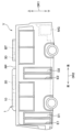
本実施形態について、図1~図4を参照して説明する。本実施形態では、本開示の車両空調システムをバス車両Vの空調システム1に適用した例について説明する。図1、図2等に示す各矢印は、上下を示す矢印がバス車両Vの上下方向DR1、前後を示す矢印がバス車両Vの前後方向DR2、左右を示す矢印がバス車両Vの幅方向DR3を示している。
(First embodiment)
This embodiment will be described with reference to FIGS. 1 to 4. FIG. In this embodiment, an example in which the vehicle air conditioning system of the present disclosure is applied to an
図1および図2に示すように、バス車両Vは、幅方向DR3の左側の側面のうち、前方部分および中央部分の2か所に対して乗降口E1、E2が設けられている。乗降口E1、E2のそれぞれには、ドアD1、D2が設けられている。このD1、D2は、乗員が乗降する際に開閉される乗降ドアである。ドアD1、D2は、折り戸型ドアで構成されている。なお、ドアD1、D2は、開き戸型ドア、引き戸型ドア等で構成されていてもよい。 As shown in FIGS. 1 and 2, the bus V is provided with entrances E1 and E2 at two locations, a front portion and a central portion, on the left side surface in the width direction DR3. Doors D1 and D2 are provided at the entrances E1 and E2, respectively. D1 and D2 are doors that are opened and closed when passengers get on and off. Doors D1 and D2 are configured as folding doors. Note that the doors D1 and D2 may be composed of a hinged door, a sliding door, or the like.
バス車両Vは、幅方向DR3の右側の側面に乗降ドアが設けられておらず、幅方向DR3の右側の側面の全体がサイドパネルSPで覆われている。サイドパネルSPは、バス車両Vの側面を構成するパネルである。これにより、バス車両Vは、幅方向DR3の左側からの乗降が可能になっている。なお、本開示では、バス車両Vの側面に設定される窓や非常口の開閉ドア等は、サイドパネルSPの一部を構成するものとする。 The bus vehicle V is not provided with a boarding/alighting door on the right side surface in the width direction DR3, and the entire right side surface in the width direction DR3 is covered with a side panel SP. The side panel SP is a panel that constitutes the side surface of the bus vehicle V. As shown in FIG. As a result, the bus V can be boarded and alighted from the left side in the width direction DR3. In addition, in this disclosure, the windows set on the side surface of the bus vehicle V, the opening/closing door of the emergency exit, and the like constitute a part of the side panel SP.
バス車両Vは、電気エネルギを駆動源として走行する電気自動車として構成されている。バス車両Vには、走行用電動機MGおよび走行用電動機MGに供給する電力が蓄えられたバッテリBTが搭載されている。 The bus vehicle V is configured as an electric vehicle that runs using electrical energy as a drive source. The bus vehicle V is equipped with an electric motor MG for traveling and a battery BT storing electric power to be supplied to the electric motor MG for traveling.
バッテリBTは、充放電可能な複数の電池セルを電気的に直列に接続した直列接続体で構成されている。なお、バッテリBTは、複数の電池セルの一部が並列に接続されていてもよい。 The battery BT is composed of a series connection body in which a plurality of chargeable/dischargeable battery cells are electrically connected in series. Battery BT may have a plurality of battery cells partially connected in parallel.
バッテリBTは、図示しない電力変換装置および走行用電動機MGに接続されている。電力変換装置は、例えば、バッテリBTから供給された直流電流を交流電流に変換し、この交流電流を走行用電動機MG等の各種電気負荷に供給する装置である。 The battery BT is connected to a power conversion device (not shown) and a traction motor MG. The power conversion device is, for example, a device that converts a direct current supplied from the battery BT into an alternating current and supplies the alternating current to various electric loads such as the traction motor MG.
バッテリBTは、バス車両Vの天井部分に配置されている。具体的には、バッテリBTは、バス車両VのルーフパネルRP上に設置されている。バッテリBTを天井部分に配置することで、バス車両Vは、バス車両Vの床の段差が低減され、乗員が乗り降りし易くなっている。 The battery BT is arranged in the ceiling portion of the bus vehicle V. As shown in FIG. Specifically, the battery BT is installed on the roof panel RP of the bus vehicle V. As shown in FIG. By arranging the battery BT in the ceiling portion, the bus V has a reduced level difference on the floor of the bus V, making it easier for passengers to get on and off.
バッテリBTは、バス車両Vに搭載された発熱機器である。バッテリBTは、バス車両Vの走行中の電力供給等を行うと自己発熱することで、バッテリBTが過度に高温になることがある。また、バッテリBTは、夏季における駐車中等にもバッテリBTが過度に高温になることがある。バッテリBTが過度に高温になると、電池セルの劣化が促進されることで電池寿命が大幅に低下してしまう。このため、バッテリBTが過度に高温にならないように、バッテリBTの温度を調整する必要がある。 The battery BT is a heat-generating device mounted on the bus vehicle V. As shown in FIG. The battery BT generates heat by supplying electric power while the bus V is running, and the temperature of the battery BT may become excessively high. Also, the battery BT may become excessively hot during parking in summer. When the temperature of the battery BT becomes excessively high, deterioration of the battery cells is accelerated, resulting in a significant reduction in battery life. Therefore, it is necessary to adjust the temperature of the battery BT so that the temperature of the battery BT does not become excessively high.
これらを加味し、バス車両Vは、室内を空調する機器を利用してバッテリBTの温度を調整可能になっている。換言すれば、バス車両Vの空調システム1は、室内の空調だけでなく、バッテリBTを対象機器としてバッテリBTの温度を調整可能に構成されている。
In consideration of these, the bus vehicle V can adjust the temperature of the battery BT using equipment for air-conditioning the interior of the vehicle. In other words, the air-
バス車両Vには、図2に示すように、バス車両Vの室内に複数の空調ゾーンZが設定されている。具体的には、バス車両Vには、室内左側のドア側ゾーンZdと室内右側のパネル側ゾーンZpといった2つの空調ゾーンZが設定されている。ドア側ゾーンZdは、バス車両Vの室内のうち、ドアD1、D2によって室外と隔てられる空調ゾーンZである。パネル側ゾーンZpは、バス車両Vの室内のうち、サイドパネルSPによって室外と隔てられる空調ゾーンZである。 A plurality of air-conditioning zones Z are set in the interior of the bus V, as shown in FIG. Specifically, the bus V has two air-conditioning zones Z, a door-side zone Zd on the left side of the room and a panel-side zone Zp on the right side of the room. The door-side zone Zd is an air-conditioning zone Z in the interior of the bus vehicle V that is separated from the exterior by doors D1 and D2. The panel-side zone Zp is an air-conditioning zone Z in the interior of the bus vehicle V that is separated from the exterior by the side panel SP.
空調システム1は、複数の空調ゾーンZのそれぞれに対応して複数の空調機10、20が設けられている。すなわち、空調システム1は、ドア側ゾーンZdに対応するドア側空調機10、パネル側ゾーンZpに対応するパネル側空調機20が設けられている。図3に示すように、ドア側空調機10およびパネル側空調機20のそれぞれは、蒸気圧縮式の冷凍サイクルRC1、RC2を含んでいる。
The
ドア側空調機10は、第1圧縮機11、第1放熱器12、第1室内膨張弁13、第1室内蒸発器14を備える。パネル側空調機20は、第2圧縮機21、第2放熱器22、第2室内膨張弁23、第2室内蒸発器24、第2機器用膨張弁25、第2機器用蒸発器26、第2室内側開閉弁27、第2機器側開閉弁28を備える。
The door-
第1圧縮機11および第2圧縮機21は、冷媒を圧縮して吐出する機器である。第1圧縮機11および第2圧縮機21は、圧縮機構を電動モータで駆動する電動圧縮機で構成されている。第1圧縮機11および第2圧縮機21は、冷媒の吐出能力が後述する制御装置100からの制御信号に応じて制御される。
The first compressor 11 and the
第1放熱器12および第2放熱器22は、第1圧縮機11および第2圧縮機21から吐出された冷媒を外部に放熱させる機器である。第1放熱器12および第2放熱器22は、出口側での冷媒が過冷却度を有するサブクール状態となるように、凝縮部121、221、受液部122、222、過冷却部123、223を有する。凝縮部121、221は、冷媒を外部に放熱させることで冷媒を凝縮させる熱交換器である。受液部122、222は、凝縮部121、221を通過した冷媒の気液を分離するとともに、サイクル内で余剰となる冷媒を貯留する気液分離器である。過冷却部123、223は、受液部122、222に貯留された液冷媒を外部に放熱させることで冷却する熱交換器である。
The
第1室内膨張弁13および第2室内膨張弁23は、第1放熱器12および第2放熱器22を通過した冷媒を所望の圧力まで減圧膨張させる減圧部である。第1室内膨張弁13および第2室内膨張弁23は、第1室内蒸発器14および第2室内蒸発器24の冷媒出口側の過熱度が所定値になるように絞り開度を調整する温度式膨張弁で構成されている。なお、第1室内膨張弁13および第2室内膨張弁23は、機械式の膨張弁に限らず電動式の膨張弁で構成されていてもよい。
The first
第1室内蒸発器14および第2室内蒸発器24は、第1室内膨張弁13および第2室内膨張弁23で減圧された冷媒を蒸発させる熱交換器である。第1室内蒸発器14および第2室内蒸発器24には、第1室内ファン141および第2室内ファン241が併設されている。第1室内ファン141および第2室内ファン241は、羽根車を電動モータによって回転させる電動ファンで構成されている。
The first
第1室内ファン141は、ドア側ゾーンZdに空気を送風する送風ファンである。第1室内蒸発器14は、第1室内膨張弁13で減圧された冷媒を第1室内ファン141から送風される空気と熱交換させて冷媒を蒸発させる。すなわち、第1室内蒸発器14は、ドア側ゾーンZdに吹き出す前の空気から吸熱して冷媒を蒸発させる。これにより、第1室内蒸発器14にて冷却および除湿された空気がドア側ゾーンZdに向けて吹き出される。
The first
第2室内ファン241は、パネル側ゾーンZpに空気を送風する送風ファンである。第2室内蒸発器24は、第2室内膨張弁23で減圧された冷媒を第2室内ファン241から送風される空気と熱交換させて冷媒を蒸発させる。すなわち、第2室内蒸発器24はパネル側ゾーンZpに吹き出す前の空気から吸熱して冷媒を蒸発させる。これにより、第2室内蒸発器24にて冷却および除湿された空気がパネル側ゾーンZpに向けて吹き出される。
The second
ここで、パネル側空調機20には、第2機器用膨張弁25および第2機器用蒸発器26が設けられている。第2機器用膨張弁25および第2機器用蒸発器26は、冷媒流れに対して第2室内膨張弁23および第2室内蒸発器24と並列に設けられている。
Here, the panel-
第2機器用膨張弁25は、第2放熱器22を通過した冷媒を所望の圧力まで減圧膨張させる減圧部である。第2機器用膨張弁25は、第2放熱器22と第2室内膨張弁23とをつなぐ冷媒配管から分岐した冷媒配管に設けられている。第2機器用膨張弁25は、冷媒流れに対して第2室内膨張弁23と並列に設けられている。第2機器用膨張弁25は、第2機器用蒸発器26の冷媒出口側の過熱度が所定値になるように絞り開度を調整する温度式膨張弁で構成されている。なお、第2機器用膨張弁25は、機械式の膨張弁に限らず電動式の膨張弁で構成されていてもよい。
The second
第2機器用蒸発器26は、第2機器用膨張弁25で減圧された冷媒を蒸発させるチラーである。第2機器用蒸発器26は、第2機器用膨張弁25で減圧された冷媒を流す冷媒流路261、後述の冷却回路31を循環する熱媒体を流す熱媒体流路262を有する。
The
第2機器用蒸発器26は、冷媒流路261を流れる冷媒を熱媒体流路262と熱交換させて冷媒を蒸発させる。熱媒体流路262を流れる熱媒体は、冷媒流路261を流れる冷媒から吸熱されることで冷却される。
The
図示しないが、第2室内蒸発器24および第2機器用蒸発器26のうち一方の蒸発器の冷媒出口側には、一方の蒸発器における圧力を所望の圧力に調整するための蒸発圧力調整弁が設けられている。これにより、第2室内蒸発器24および第2機器用蒸発器26の冷媒の圧力をそれぞれの熱負荷に応じて調整することが可能となっている。
Although not shown, on the refrigerant outlet side of one of the second
パネル側空調機20には、第2室内側開閉弁27および第2機器側開閉弁28が設けられている。第2室内側開閉弁27および第2機器側開閉弁28は、第2放熱器22を通過した後の冷媒の流路を切り替える流路切替弁として機能する。第2室内側開閉弁27および第2機器側開閉弁28は、電磁弁であり、後述する制御装置100からの制御信号に応じて制御される。
The panel-
第2室内側開閉弁27は、第2放熱器22を通過した冷媒を第2室内膨張弁23に導く冷媒配管に設けられている。第2室内側開閉弁27は、第2室内蒸発器24への冷媒の流れを許容する状態と、第2室内蒸発器24への冷媒の流れを遮断する状態とを切り替える切替部である。
The second indoor opening/closing
第2機器側開閉弁28は、第2放熱器22を通過した冷媒を第2機器用膨張弁25に導く冷媒配管に設けられている。第2機器側開閉弁28は、第2機器用蒸発器26への冷媒の流れを許容する第2許容状態と、第2機器用蒸発器26への冷媒の流れを遮断する第2遮断状態とを切り替えるドア側切替部である。
The second device side on-off
一方、ドア側空調機10は、室内に吹き出す空気から吸熱する第1室内蒸発器14を有するだけで、熱媒体から吸熱する吸熱器を含んでいない。すなわち、ドア側空調機10には、第2機器用膨張弁25および第2機器用蒸発器26に相当する構成が設けられていない。
On the other hand, the door-
空調システム1には、前述の冷却回路31を含む冷却機30が設けられている。冷却機30は、バッテリBTを対象機器として冷却する。冷却機30は、複数の空調機10、20の一部における吸熱作用を利用して熱媒体を冷却することでバッテリBTの温度を調整する。熱媒体は、例えば、エチレングリコール等を含む不凍液を採用することができる。
The
冷却機30は、熱媒体を循環させる冷却回路31を備える。冷却回路31には、循環ポンプ32、第2機器用蒸発器26の熱媒体流路262、三方弁33、バッテリ冷却部34、ラジエータ35が設けられている。
The cooler 30 includes a
循環ポンプ32は、熱媒体を第2機器用蒸発器26の熱媒体流路262に圧送する電動ポンプである。循環ポンプ32は、後述する制御装置100からの制御信号に応じて圧送能力が制御される。
The
第2機器用蒸発器26の熱媒体流路262の出口側には、三方弁33の流入口が接続されている。三方弁33は、1つの流入口と2つの流出口とを有し、2つの流出口の選択的に開閉可能な電気式の三方流量調整弁である。三方弁33は、後述する制御装置100からの制御信号に応じて制御される。
The inlet of the three-
三方弁33の一方の流出口側には、バッテリ冷却部34の入口に接続されている。バッテリ冷却部34は、バッテリBTを構成する複数の電池セルに接触するように配置された複数の熱交換流路を有し、熱交換流路を流れる熱媒体と電池セルとを熱交換させることによってバッテリBTを冷却する。
One outlet side of the three-
このようなバッテリ冷却部34は、隣り合う電池セルの間に熱交換流路を配置することによって実現可能である。なお、バッテリ冷却部34は、電池セルを収容するケースに熱交換流路を設けること等によって、バッテリBTと一体に形成されていてもよい。
Such a
三方弁33の他方の流出口側には、ラジエータ35の入口に接続されている。ラジエータ35は、第2機器用蒸発器26を通過した熱媒体を外気と熱交換させて放熱させる熱交換器である。
The other outlet side of the three-
バッテリ冷却部34およびラジエータ35は、バッテリ冷却部34およびラジエータ35の出口側に設けられた合流部を介して循環ポンプ32の吸入口に接続されている。バッテリ冷却部34およびラジエータ35は、熱媒体流れに対して並列に接続されている。
The
次に、空調システム1の電子制御部である制御装置100について説明する。制御装置100は、プロセッサ、メモリを有するコンピュータとその周辺回路で構成されている。制御装置100は、メモリに記憶されたプログラムに基づいて各種演算、処理を行い、その出力側に接続された機器を制御する。なお、制御装置100のメモリは、非遷移的実体的記憶媒体で構成されている。
Next, the
制御装置100の出力側には、第1圧縮機11、第1室内ファン141、第2圧縮機21、第2室内ファン241、第2室内側開閉弁27、第2機器側開閉弁28、循環ポンプ32、三方弁33等が接続されている。本実施形態では、制御装置100のうち、ドア側空調機10およびパネル側空調機20を制御するソフトウエアおよびハードウエアが、空調制御部100aを構成している。
On the output side of the
制御装置100の入力側には、制御装置100は、空調制御用および電池温調用のセンサ群101が接続されている。このセンサ群101は、内気温センサ、外気温センサ、日射センサ、各蒸発器14、16、24の冷媒出口側の圧力および温度を検出するPTセンサ、バッテリBTの温度を検出するバッテリ温度センサ等が含まれている。制御装置100には、センサ群101の検出信号が入力される。これにより、空調システム1は、センサ群101で検出した物理量に対応して、室内に送風される送風空気の温度およびバッテリBTの温度等を調整することができる。
An input side of the
また、制御装置100の入力側には、種々の入力操作に用いられる操作パネル102が接続されている。操作パネル102は、インストルメントパネル付近に配置されており、各種操作スイッチを有している。制御装置100には、操作パネル102に設けられた各種操作スイッチからの操作信号が入力される。
An
操作パネル102の各種操作スイッチには、オートスイッチ、運転モード切替スイッチ、風量設定スイッチ、温度設定スイッチ、吹出モード切替スイッチ等が含まれている。空調システム1は、操作パネル102による入力を受け付けることで、空調システム1の運転モードを適宜切り替えることができる。具体的には、制御装置100は、第2室内側開閉弁27および第2機器側開閉弁28を制御してパネル側空調機20の冷媒の流れ方を変更することで、空調システム1の運転モードを切り替える。
Various operation switches of the
以下、空調システム1の作動について説明する。空調システム1は、運転モードとして、室内冷房および機器温調を実行可能に構成されている。室内冷房は、ドア側空調機10およびパネル側空調機20によって室内の冷房を行う運転モードである。機器温調は、ドア側空調機10およびパネル側空調機20によって室内の冷房およびバッテリBTの温調それぞれを行う運転モードである。以下では、室内冷房および機器温調の空調システム1の作動を説明する。
The operation of the
<室内冷房>
室内冷房は、第1室内蒸発器14および第2室内蒸発器24で所望の温度に冷却した空気をバス車両Vの室内に吹き出す運転モードである。室内冷房は、例えば、運転モード切替スイッチによって運転モードが冷房モードに設定されると空調システム1によって実行される。
<Indoor cooling>
The indoor cooling is an operation mode in which air cooled to a desired temperature by the first
制御装置100は、室内冷房時における各種機器の作動状態をセンサ群101の検出信号および操作パネル102の操作信号を用いて適宜決定する。例えば、制御装置100は、第2室内側開閉弁27が開状態となり、第2機器側開閉弁28が閉状態となるように、各開閉弁17、18を制御する。制御装置100は、各圧縮機11、21、各室内ファン141、241等の他の機器に対する制御信号について、センサ群101の検出信号および操作パネル102の操作信号を用いて適宜決定する。
The
ドア側空調機10では、室内冷房時に、第1圧縮機11から吐出された高圧冷媒が第1放熱器12の凝縮部121に流入して放熱する。凝縮部121を通過した冷媒は、受液部122に流入して気液が分離される。そして、受液部122で分離された液冷媒は過冷却部123に流入して放熱する。
In the door-
過冷却部123から流出した冷媒は、第1室内膨張弁13に流入し、第1室内膨張弁13にて所望の圧力となるまで減圧される。第1室内膨張弁13で減圧された冷媒は、第1室内蒸発器14に流入する。
The refrigerant that has flowed out of the
第1室内蒸発器14に流入した冷媒は、第1室内ファン141からの送風空気から吸熱して蒸発する。すなわち、第1室内蒸発器14に流入した冷媒は、ドア側ゾーンZdに吹き出す前の空気から吸熱して蒸発する。これにより、ドア側ゾーンZdには、第1室内蒸発器14で所望の温度に冷却された空気が吹き出される。
The refrigerant that has flowed into the first
第1室内蒸発器14を通過した冷媒は、第1圧縮機11に吸入される。第1圧縮機11に吸入された冷媒は、第1圧縮機11にて再び高圧冷媒となるまで圧縮される。
The refrigerant that has passed through the first
一方、パネル側空調機20では、ドア側空調機10と同様に、第2圧縮機21から吐出された高圧冷媒が第2放熱器22の凝縮部221に流入して放熱する。凝縮部221を通過した冷媒は、受液部222に流入して気液が分離される。そして、受液部222で分離された液冷媒は過冷却部223に流入して放熱する。
On the other hand, in the panel-
過冷却部223から流出した冷媒は、第2室内膨張弁23に流入し、第2室内膨張弁23にて所望の圧力となるまで減圧される。なお、室内冷房時は、第2機器側開閉弁28が閉状態になっているので、冷媒が第2機器用膨張弁25に流入せず、冷媒の全量が第2室内膨張弁23にて減圧される。
The refrigerant that has flowed out of the
第2室内膨張弁23で減圧された冷媒は、第2室内蒸発器24に流入する。第2室内蒸発器24に流入した冷媒は、第2室内ファン241からの送風空気から吸熱して蒸発する。すなわち、第2室内蒸発器24に流入した冷媒は、パネル側ゾーンZpに吹き出す前の空気から吸熱して蒸発する。これにより、パネル側ゾーンZpには、第2室内蒸発器24で所望の温度に冷却された空気が吹き出される。
The refrigerant decompressed by the second
第2室内蒸発器24を通過した冷媒は、第2圧縮機21に吸入される。第2圧縮機21に吸入された冷媒は、第2圧縮機21にて再び高圧冷媒となるまで圧縮される。
The refrigerant that has passed through the second
以上の如く、室内冷房時には、第1室内蒸発器14で冷却された空気をドア側ゾーンZdに吹き出すとともに、第2室内蒸発器24で冷却された空気をパネル側ゾーンZpに吹き出すことによって、室内の冷房が実現される。
As described above, when the room is cooled, the air cooled by the first
<機器温調>
機器温調は、第1室内蒸発器14および第2室内蒸発器24で所望の温度に冷却した空気をバス車両Vの室内に吹き出しつつ、冷媒の蒸発潜熱を利用して対象機器であるバッテリBTの温度を調整する運転モードである。機器温調は、例えば、オートスイッチがオンされた状態で、バッテリBTの温度が適正温度の上限を上回ると空調システム1によって実行される。なお、機器温調の実行条件は、上述のものと異なっていてもよい。
<Equipment temperature control>
Equipment temperature control is performed by blowing air cooled to a desired temperature by the first
制御装置100は、機器温調時における各種機器の作動状態をセンサ群101の検出信号および操作パネル102の操作信号を用いて適宜決定する。例えば、制御装置100は、第2室内側開閉弁27および第2機器側開閉弁28それぞれが開状態となるように各開閉弁27、28を制御する。制御装置100は、第2機器用蒸発器26の熱媒体流路262を通過した熱媒体の全量がバッテリ冷却部34に流れるように、三方弁33を制御する。制御装置100は、各圧縮機11、21、各室内ファン141、241、循環ポンプ32等の他の機器に対する制御信号について、センサ群101の検出信号および操作パネル102の操作信号を用いて適宜決定する。
The
機器冷却時には、ドア側空調機10では、第1圧縮機11から吐出された高圧冷媒が、室内冷房時と同様に第1放熱器12に流入して放熱する。放熱器12から流出した冷媒は、第1室内膨張弁13に流入する。
During cooling of the equipment, in the door-
第1室内膨張弁13に流入した冷媒は、第1室内膨張弁13にて所望の圧力となるまで減圧された後、第1室内蒸発器14に流入する。第1室内蒸発器14に流入した冷媒は、第1室内ファン141からの送風空気から吸熱して蒸発する。これにより、ドア側ゾーンZdには、第1室内蒸発器14で所望の温度に冷却された空気が吹き出される。
The refrigerant that has flowed into the first
第1室内蒸発器14を通過した冷媒は、第1圧縮機11に吸入される。第1圧縮機11に吸入された冷媒は、第1圧縮機11にて再び高圧冷媒となるまで圧縮される。
The refrigerant that has passed through the first
一方、パネル側空調機20では、室内冷房時と同様に、第2圧縮機21から吐出された高圧冷媒が第2放熱器22に流入して放熱する。第2放熱器22から流出した冷媒は、第2室内膨張弁23および第2機器用膨張弁25に流入する。
On the other hand, in the panel-
第2室内膨張弁23に流入した冷媒は、第2室内膨張弁23にて所望の圧力となるまで減圧される。第2室内膨張弁23で減圧された冷媒は、第2室内蒸発器24に流入する。
The refrigerant that has flowed into the second
第2室内蒸発器24に流入した冷媒は、第2室内ファン241からの送風空気から吸熱して蒸発する。すなわち、第2室内蒸発器24に流入した冷媒は、パネル側ゾーンZpに吹き出す前の空気から吸熱して蒸発する。これにより、パネル側ゾーンZpには、第2室内蒸発器24で所望の温度に冷却された空気が吹き出される。
The refrigerant that has flowed into the second
一方、第2機器用膨張弁25に流入した冷媒は、第2機器用膨張弁25にて所望の圧力となるまで減圧された後、第2機器用蒸発器26に流入する。第2機器用蒸発器26に流入した冷媒は、冷却回路31を流れる熱媒体から吸熱して蒸発する。これにより、冷却回路31を流れる熱媒体が第2機器用蒸発器26の熱媒体流路262を通過する際に冷却される。
On the other hand, the refrigerant that has flowed into the second
第2室内蒸発器24を通過した冷媒および第2機器用蒸発器26を通過した冷媒は、第2圧縮機21に吸入される。第2圧縮機21に吸入された冷媒は、第2圧縮機21にて再び高圧冷媒となるまで圧縮される。
The refrigerant that has passed through the second
ここで、第2機器用蒸発器26で冷却された熱媒体は、バッテリ冷却部34に流れ、バッテリBTから吸熱する。これにより、バッテリBTが冷却される。すなわち、機器温調時には、第2機器用蒸発器26における冷媒の蒸発による吸熱作用を利用してバッテリBTが冷却される。
Here, the heat medium cooled by the
以上の如く、機器温調時には、各室内蒸発器14、24で冷却された空気を各ゾーンZd、Zpに吹き出すとともに、第2機器用蒸発器26にて冷却された熱媒体をバッテリ冷却部34に供給することで、室内の冷房およびバッテリBTの冷却が実現される。
As described above, during the device temperature control, the air cooled by the
以上説明した空調システム1は、バス車両Vの室内を複数の空調ゾーンZに分けるとともに、当該複数の空調ゾーンZそれぞれに対応して設けた複数の空調機10、20によって複数の空調ゾーンZの空調を行うように構成されている。具体的には、バス車両Vは、幅方向DR3の一方の側面にドアDが1つ以上設けられ、幅方向の他方の側面にサイドパネルSPが設けられ、幅方向DR3の一方側にドア側ゾーンZdが設定され、幅方向DR3の他方側にパネル側ゾーンZpが設定されている。これによると、各々の空調ゾーンZに適した空調風を提供することができるので、室内の快適性を確保することが可能となる。
The air-
ここで、空調ゾーンZのうち、バス車両VのドアD1、D2近傍のドア側ゾーンZdは、バス車両VのドアD1、D2から離れたパネル側ゾーンZpに比べて、ドアD1、D2の開閉に伴う換気ロスが生じ易い、温度が低くなり難い。 Here, in the air-conditioning zone Z, the door side zone Zd near the doors D1 and D2 of the bus vehicle V is more likely to open and close the doors D1 and D2 than the panel side zone Zp away from the doors D1 and D2 of the bus vehicle V. Ventilation loss is likely to occur, and the temperature is difficult to decrease.
このことを考慮して、本実施形態の空調システム1は、パネル側空調機20が第2機器用蒸発器26を含み、ドア側空調機10が熱媒体から吸熱する吸熱器を含んでいない。このような構成では、機器温調時における熱媒体からの吸熱量が、図4に示すように、パネル側空調機20に比べてドア側空調機10の方が小さくなる。
In consideration of this, in the
ドア側空調機10は、機器温調時に、熱媒体から吸熱しないので、ドア側ゾーンZdに吹き出す空気からの吸熱量が大きくなり、ドア側ゾーンZdの温度を充分に低下させることができる。すなわち、ドア側空調機10は、冷凍サイクルRC1の吸熱作用をドア側ゾーンZdに吹き出す空気に集中させることができる。このため、バッテリBTの冷却を行う場合であっても、バス車両VのドアD1、D2に近いドア側ゾーンZdにおける快適性を確保することができる。すなわち、空調システム1によれば、乗降ドアによる乗降口E1、E2の開閉に起因する換気ロスが生じ易い空調ゾーンZの快適性を確保することができる。
Since the door-
(第1実施形態の変形例)
第1実施形態では、バス車両Vとして、幅方向DR3の左側の側面のうち、前方部分および中央部分の2か所に乗降口E1、E2およびドアD1、D2が設けられているものを例示したが、バス車両Vは、これに限定されない。
(Modified example of the first embodiment)
In the first embodiment, the bus V is provided with entrances E1 and E2 and doors D1 and D2 at two locations, a front portion and a central portion, on the left side surface in the width direction DR3. However, the bus vehicle V is not limited to this.
バス車両Vは、例えば、幅方向DR3の一方の側面に対して1つのドアが設けられ、他方の側面にサイドパネルSPが設けられていてもよい。具体的には、バス車両Vは、図5に示すように、幅方向DR3の左側の側面のうち、前方部分の1か所に乗降口E1およびドアD1が設けられていてもよい。この場合、室内前方にドア側ゾーンZdおよび室内後方にパネル側ゾーンZpを設定し、ドア側ゾーンZdをドア側空調機10で空調しつつ、パネル側ゾーンZpをパネル側空調機20で空調することで、第1実施形態と同様の効果を得ることができる。なお、バス車両Vは、例えば、幅方向DR3の右側の側面に対して1つ以上のドアが設けられていてもよい。 For example, the bus V may be provided with one door on one side in the width direction DR3 and a side panel SP on the other side. Specifically, as shown in FIG. 5, the bus V may be provided with an entrance E1 and a door D1 at one point in the front portion of the left side surface in the width direction DR3. In this case, a door-side zone Zd is set at the front of the room and a panel-side zone Zp is set at the rear of the room. Thus, the same effects as those of the first embodiment can be obtained. In addition, the bus vehicle V may be provided with one or more doors on the right side surface in the width direction DR3, for example.
バス車両Vは、例えば、幅方向DR3の両側の側面のうち前方または後方の一方に1つ以上のドアが設けられ、他方にサイドパネルSPが設けられていてもよい。具体的には、バス車両Vは、図6に示すように、幅方向DR3の両側の側面のうち、前方部分の2か所に乗降口E1、E2およびドアD1、D2が設けられていてもよい。この場合、室内前方にドア側ゾーンZdおよび室内後方にパネル側ゾーンZpを設定し、ドア側ゾーンZdをドア側空調機10で空調しつつ、パネル側ゾーンZpをパネル側空調機20で空調することで、第1実施形態と同様の効果を得ることができる。バス車両Vは、例えば、幅方向DR3の両側の側面のうち、室内後方にドアが設けられていてもよい。 For example, the bus vehicle V may be provided with one or more doors on one of the front and rear sides of both side surfaces in the width direction DR3, and a side panel SP on the other side. Specifically, as shown in FIG. 6, the bus V is provided with entrances E1 and E2 and doors D1 and D2 at two front portions of both side surfaces in the width direction DR3. good. In this case, a door-side zone Zd is set at the front of the room and a panel-side zone Zp is set at the rear of the room. Thus, the same effects as those of the first embodiment can be obtained. The bus vehicle V may be provided with a door at the rear of the room, for example, among the side surfaces on both sides in the width direction DR3.
(第2実施形態)
次に、第2実施形態について、図7を参照して説明する。本実施形態では、第1実施形態と異なる部分について主に説明する。
(Second embodiment)
Next, a second embodiment will be described with reference to FIG. In this embodiment, portions different from the first embodiment will be mainly described.
本実施形態では、室内の前後、左右の4か所に空調ゾーンZが設定されているバス車両Vに空調システム1を適用した例について説明する。図7に示すように、バス車両Vは、幅方向DR3の左側の側面のうち、前方部分および中央部分の2か所に対して乗降口E1、E2およびドアD1、D2が設けられている。バス車両Vには、室内左側における前方の第1ドア側ゾーンZd1、後方の第2ドア側ゾーンZd2、室内右側の前方の第1パネル側ゾーンZp1、後方の第2パネル側ゾーンZp2といった4つの空調ゾーンZが設定されている。
In this embodiment, an example will be described in which the
空調システム1は、4つの空調ゾーンZのそれぞれに対応して第1ドア側空調機10A、第2ドア側空調機10B、第1パネル側空調機20A、第2パネル側空調機20Bが設けられている。なお、各ドア側空調機10A、10Bは、第1実施形態で説明したドア側空調機10と同様に構成される。また、各パネル側空調機20A、20Bは、第1実施形態で説明したパネル側空調機20と同様に構成される。
The air-
その他の構成は、第1実施形態と同様である。本実施形態の空調システム1は、第1実施形態と共通の構成または均等な構成から奏される効果を第1実施形態と同様に得ることができる。
Other configurations are the same as those of the first embodiment. The air-
本実施形態の空調システム1は、室内の前後、左右の4か所に空調ゾーンZが設定されているので、室内の前後、左右の各空間に適した空調風を提供することができるので、室内の快適性を充分に確保することが可能となる。
The air-
(第2実施形態の変形例)
第2実施形態では、バス車両Vとして、幅方向DR3の左側の側面のうち、前方部分および中央部分の2か所に乗降口E1、E2およびドアD1、D2が設けられているものを例示したが、バス車両Vは、これに限定されない。
(Modification of Second Embodiment)
In the second embodiment, the bus V is provided with entrances E1, E2 and doors D1, D2 at two locations, the front portion and the center portion, on the left side surface in the width direction DR3. However, the bus vehicle V is not limited to this.
バス車両Vは、例えば、幅方向DR3の両側の側面のうち前方または後方の一方に1つ以上のドアが設けられ、他方にサイドパネルSPが設けられていてもよい。具体的には、バス車両Vは、図8に示すように、幅方向DR3の両側の側面のうち、前方部分の2か所に乗降口E1、E2およびドアD1、D2が設けられていてもよい。この場合、室内前方に第1ドア側ゾーンZd1、第2ドア側ゾーンZd2を設定し、各ドア側ゾーンZd1、Zd2を各ドア側空調機10A、10Bで空調することで、第2実施形態と同様に、室内前方に適した空調風を提供することができる。また、室内後方に第1パネル側ゾーンZp1、第2パネル側ゾーンZp2を設定し、各パネル側ゾーンZp1、Zp2を各パネル側空調機20A、20Bで空調することで、第2実施形態と同様に、室内後方に適した空調風を提供することができる。なお、バス車両Vは、例えば、幅方向DR3の両側の側面のうち、後方部分に対して1つ以上のドアが設けられていてもよい。
For example, the bus vehicle V may be provided with one or more doors on one of the front and rear sides of both side surfaces in the width direction DR3, and a side panel SP on the other side. Specifically, as shown in FIG. 8, the bus V is provided with entrances E1 and E2 and doors D1 and D2 at two front portions of both side surfaces in the width direction DR3. good. In this case, a first door-side zone Zd1 and a second door-side zone Zd2 are set in front of the room, and the door-side zones Zd1 and Zd2 are air-conditioned by the door-
バス車両Vは、例えば、幅方向DR3の一方の側面に対して1つのドアが設けられ、他方の側面にサイドパネルSPが設けられていてもよい。 For example, the bus V may be provided with one door on one side in the width direction DR3 and a side panel SP on the other side.
具体的には、バス車両Vは、図9に示すように、幅方向DR3の左側の側面のうち、前方部分の1か所に乗降口E1およびドアD1が設けられていてもよい。この場合、室内左側の前方にドア側ゾーンZdを設定し、ドア側ゾーンZdをドア側空調機10で空調することで、室内左側の前方の空間に適した空調風を提供することができる。また、室内左側の前方に第1パネル側ゾーンZp1を設定し、室内後方に第2パネル側ゾーンZp2、第3パネル側ゾーンZp3を設定する。そして、各パネル側ゾーンZp1、Zp2、Zp3を各パネル側空調機20A、20B、20Cで空調することで、室内の各箇所に適した空調風を提供することができる。
Specifically, as shown in FIG. 9, the bus vehicle V may be provided with an entrance E1 and a door D1 at one point in the front part of the left side surface in the width direction DR3. In this case, by setting the door-side zone Zd in front of the left side of the room and air-conditioning the door-side zone Zd with the door-
また、バス車両Vは、図10に示すように、幅方向DR3の左側の側面のうち、後方部分の1か所に乗降口E1およびドアD1が設けられていてもよい。この場合、室内左側の後方にドア側ゾーンZdを設定し、ドア側ゾーンZdをドア側空調機10で空調することで、室内左側の後方の空間に適した空調風を提供することができる。また、室内前方に第1パネル側ゾーンZp1、第2パネル側ゾーンZp2を設定し、室内右側の後方に第3パネル側ゾーンZp3を設定する。そして、各パネル側ゾーンZp1、Zp2、Zp3を各パネル側空調機20A、20B、20Cで空調することで、室内の各箇所に適した空調風を提供することができる。なお、バス車両Vは、例えば、幅方向DR3の右側の側面に対して1つ以上のドアが設けられていてもよい。
In addition, as shown in FIG. 10, the bus V may be provided with an entrance E1 and a door D1 at one location in the rear portion of the left side surface in the width direction DR3. In this case, by setting the door-side zone Zd at the rear left side of the room and air-conditioning the door-side zone Zd with the door-
(第3実施形態)
次に、第3実施形態について、図11を参照して説明する。本実施形態では、第2実施形態と異なる部分について主に説明する。
(Third Embodiment)
Next, a third embodiment will be described with reference to FIG. In this embodiment, portions different from the second embodiment will be mainly described.
本実施形態では、室内の幅方向DR3の両側に3か所ずつ空調ゾーンZが設定されているバス車両Vに空調システム1を適用した例について説明する。図11に示すように、バス車両Vは、幅方向DR3の左側の側面のうち、前方部分、中央部分、後方部分の3か所に対して乗降口E1、E2、E3およびドアD1、D2、D3が設けられている。バス車両Vの室内左側には、前方に第1ドア側ゾーンZd1、後方に第2ドア側ゾーンZd2、中央に第3ドア側ゾーンZd3といった3つの空調ゾーンZが設定されている。また、室内右側には、前方に第1パネル側ゾーンZp1、後方に第2パネル側ゾーンZp2、中央に第3パネル側ゾーンZp3といった3つの空調ゾーンZが設定されている。
In this embodiment, an example will be described in which the
空調システム1は、6つの空調ゾーンZのそれぞれに対応して第1ドア側空調機10A、第2ドア側空調機10B、第3ドア側空調機10C、第1パネル側空調機20A、第2パネル側空調機20B、第3パネル側空調機20Cが設けられている。なお、各ドア側空調機10A、10B、10Cは、第1実施形態で説明したドア側空調機10と同様に構成される。また、各パネル側空調機20A、20B、20Cは、第1実施形態で説明したパネル側空調機20と同様に構成される。
The air-
その他の構成は、第2実施形態と同様である。本実施形態の空調システム1は、第1、第2実施形態と共通の構成または均等な構成から奏される効果を第1、第2実施形態と同様に得ることができる。
Other configurations are the same as those of the second embodiment. The air-
本実施形態の空調システム1は、室内の幅方向DR3の両側に3か所ずつ空調ゾーンZが設定されているので室内の前後、左右、中央の各空間に適した空調風を提供することができるので、室内の快適性を充分に確保することが可能となる。
The air-
(第3実施形態の変形例)
第3実施形態では、バス車両Vとして、幅方向DR3の左側の側面のうち、前方部分、中央部分、後方部分の3か所に乗降口E1、E2、E3およびドアD1、D2、D3が設けられているものを例示したが、バス車両Vは、これに限定されない。
(Modified example of the third embodiment)
In the third embodiment, the bus vehicle V is provided with entrances E1, E2, and E3 and doors D1, D2, and D3 at three locations on the left side in the width direction DR3: the front portion, the center portion, and the rear portion. However, the bus vehicle V is not limited to this.
バス車両Vは、例えば、図12に示すように、幅方向DR3の左側の側面のうち前方および後方にドアD1、D2が設けられ、左側の側面の中央部分および右側の側面にサイドパネルSPが設けられていてもよい。この場合、室内左側の前方に第1ドア側ゾーンZd1、後方に第2ドア側ゾーンZd2を設定し、各ドア側ゾーンZd1、Zd2を各ドア側空調機10A、10Bで空調することで、室内左側の前方および後方に適した空調風を提供することができる。また、室内左側の中央部分に第1パネル側ゾーンZp1を設定し、室内右側の前方に第2パネル側ゾーンZp2、後方に第3パネル側ゾーンZp3、中央に第4パネル側ゾーンZp4を設定する。そして、各パネル側ゾーンZp1、Zp2、Zp3、Zp4を各パネル側空調機20A、20B、20C、20Dで空調することで、室内左側の中央部分および室内右側に適した空調風を提供することができる。なお、バス車両Vは、例えば、幅方向DR3の右側の側面に対して1つ以上のドアが設けられていてもよい。
For example, as shown in FIG. 12, the bus V is provided with doors D1 and D2 on the front and rear sides of the left side in the width direction DR3, and side panels SP on the central portion and the right side of the left side. may be provided. In this case, a first door-side zone Zd1 is set at the front of the left side of the room, and a second door-side zone Zd2 is set at the rear. Suitable conditioned air can be provided forward and rearward on the left side. In addition, the first panel side zone Zp1 is set in the central part of the left side of the room, the second panel side zone Zp2 is set in front of the right side of the room, the third panel side zone Zp3 is set in the rear, and the fourth panel side zone Zp4 is set in the center. . By air-conditioning the panel-side zones Zp1, Zp2, Zp3, and Zp4 with the panel-
また、バス車両Vは、例えば、図13に示すように、幅方向DR3の両側の側面のうち、前方部分の2か所に乗降口E1、E2およびドアD1、D2が設けられていてもよい。この場合、室内前方に第1ドア側ゾーンZd1、第2ドア側ゾーンZd2を設定し、各ドア側ゾーンZd1、Zd2を各ドア側空調機10A、10Bで空調することで、室内前方に適した空調風を提供することができる。また、室内中央に第1パネル側ゾーンZp1、第2パネル側ゾーンZp2を設定し、室内後方に第3パネル側ゾーンZp3、第4パネル側ゾーンZp4を設定する。そして、各パネル側ゾーンZp1、Zp2、Zp3、Zp4を各パネル側空調機20A、20B、20C、20Dで空調することで、室内中央および室内後方に適した空調風を提供することができる。
Further, as shown in FIG. 13, for example, the bus V may be provided with entrances E1 and E2 and doors D1 and D2 at two front portions of both side surfaces in the width direction DR3. . In this case, a first door-side zone Zd1 and a second door-side zone Zd2 are set in front of the room, and the door-side zones Zd1 and Zd2 are air-conditioned by the door-
また、バス車両Vは、例えば、図14に示すように、幅方向DR3の左側の側面のうち前方および中央にドアD1、D2が設けられ、左側の側面の後方部分および右側の側面にサイドパネルSPが設けられていてもよい。この場合、室内左側の前方に第1ドア側ゾーンZd1、中央に第2ドア側ゾーンZd2を設定し、各ドア側ゾーンZd1、Zd2を各ドア側空調機10A、10Bで空調することで、室内左側の前方および中央に適した空調風を提供することができる。また、室内左側の後方に第1パネル側ゾーンZp1を設定し、室内右側の前方に第2パネル側ゾーンZp2、後方に第3パネル側ゾーンZp3、中央に第4パネル側ゾーンZp4を設定する。そして、各パネル側ゾーンZp1、Zp2、Zp3、Zp4を各パネル側空調機20A、20B、20C、20Dで空調することで、室内左側の中央部分および室内右側に適した空調風を提供することができる。なお、バス車両Vは、例えば、幅方向DR3の右側の側面に対して1つ以上のドアが設けられていてもよい。
Further, as shown in FIG. 14, for example, the bus vehicle V is provided with doors D1 and D2 on the front and center of the left side in the width direction DR3, and side panels on the rear part of the left side and the right side. An SP may be provided. In this case, a first door-side zone Zd1 is set in front of the left side of the room, and a second door-side zone Zd2 is set in the center. A conditioned wind suitable for the left front and center can be provided. Also, the first panel side zone Zp1 is set in the rear left side of the room, the second panel side zone Zp2 is set in the front right side of the room, the third panel side zone Zp3 is set in the rear, and the fourth panel side zone Zp4 is set in the center. By air-conditioning the panel-side zones Zp1, Zp2, Zp3, and Zp4 with the panel-
(第4実施形態)
次に、第4実施形態について、図15~図17を参照して説明する。本実施形態では、第1実施形態と異なる部分について主に説明する。
(Fourth embodiment)
Next, a fourth embodiment will be described with reference to FIGS. 15 to 17. FIG. In this embodiment, portions different from the first embodiment will be mainly described.
本実施形態の空調システム1は、ドア側空調機10Xおよびパネル側空調機20Xに熱媒体から吸熱する吸熱器が設けられている。本実施形態のパネル側空調機20Xは、第1実施形態で説明したものと同様に構成されているため、パネル側空調機20Xに関する説明を省略する。
In the
図15に示すように、本実施形態のドア側空調機10Xには、第1機器用膨張弁15および第1機器用蒸発器16が設けられている。第1機器用膨張弁15および第1機器用蒸発器16は、冷媒流れに対して第1室内膨張弁13および第1室内蒸発器14と並列に設けられている。
As shown in FIG. 15 , a door-
第1機器用膨張弁15は、第1放熱器12を通過した冷媒を所望の圧力まで減圧膨張させる減圧部である。第1機器用膨張弁15は、第1放熱器12と第1室内膨張弁13とをつなぐ冷媒配管から分岐した冷媒配管に設けられている。第1機器用膨張弁15は、冷媒流れに対して第1室内膨張弁13と並列に設けられている。第1機器用膨張弁15は、第1機器用蒸発器16の冷媒出口側の過熱度が所定値になるように絞り開度を調整する温度式膨張弁で構成されている。なお、第1機器用膨張弁15は、機械式の膨張弁に限らず電動式の膨張弁で構成されていてもよい。
The first
第1機器用蒸発器16は、第1機器用膨張弁15で減圧された冷媒を蒸発させるチラーである。第1機器用蒸発器16は、第1機器用膨張弁15で減圧された冷媒を流す冷媒流路161、後述の冷却回路31を循環する熱媒体を流す熱媒体流路162を有する。
The
第1機器用蒸発器16は、冷媒流路161を流れる冷媒を熱媒体流路162と熱交換させて冷媒を蒸発させる。熱媒体流路162を流れる熱媒体は、冷媒流路161を流れる冷媒から吸熱されることで冷却される。
The
図示しないが、第1室内蒸発器14および第1機器用蒸発器16のうち一方の蒸発器の冷媒出口側には、一方の蒸発器における圧力を所望の圧力に調整するための蒸発圧力調整弁が設けられている。これにより、第1室内蒸発器14および第1機器用蒸発器16の冷媒の圧力をそれぞれの熱負荷に応じて調整することが可能となっている。
Although not shown, on the refrigerant outlet side of one of the first
ドア側空調機10Xには、第1室内側開閉弁17および第1機器側開閉弁18が設けられている。第1室内側開閉弁17および第1機器側開閉弁18は、第1放熱器12を通過した後の冷媒の流路を切り替える流路切替弁として機能する。第1室内側開閉弁17および第1機器側開閉弁18は、電磁弁であり、後述する制御装置100からの制御信号に応じて制御される。
The door-
第1室内側開閉弁17は、第1放熱器12を通過した冷媒を第1室内膨張弁13に導く冷媒配管に設けられている。第1室内側開閉弁17は、第1室内蒸発器14への冷媒の流れを許容する状態と、第1室内蒸発器14の冷媒の流れを遮断する状態とを切り替える切替部である。
The first indoor opening/closing
第1機器側開閉弁18は、第1放熱器12を通過した冷媒を第1機器用膨張弁15に導く冷媒配管に設けられている。第1機器側開閉弁18は、第1機器用蒸発器16への冷媒の流れを許容する第1許容状態と、第1機器用蒸発器16への冷媒の流れを遮断する第1遮断状態とを切り替えるパネル側切替部である。
The first device side on-off
冷却機30の冷却回路31Aには、循環ポンプ32、第1機器用蒸発器16の熱媒体流路162、第2機器用蒸発器26の熱媒体流路262、三方弁33、バッテリ冷却部34、ラジエータ35が設けられている。冷却回路31Aには、循環ポンプ32の下流に、第1機器用蒸発器16および第2機器用蒸発器26が熱媒体の流れに対して直列に接続されている。
The
具体的には、第1機器用蒸発器16は、第2機器用蒸発器26を通過した後の熱媒体が流入するように、冷却回路31Aにおいて第2機器用蒸発器26の熱媒体流れ下流側に配置されている。すなわち、第1機器用蒸発器16は、熱媒体の入口側が第2機器用蒸発器26の出口側に接続されている。
Specifically, the
このように構成される空調システム1は、制御装置100が各室内側開閉弁17、27、各機器側開閉弁18、28を制御してドア側空調機10Xおよびパネル側空調機20Xの冷媒の流れ方を変更することで、空調システム1の運転モードを切り替える。
In the
本実施形態の制御装置100は、室内冷房時に、第1室内側開閉弁17および第2室内側開閉弁27が開状態となり、第1機器側開閉弁18および第2機器側開閉弁28が閉状態となるように、各開閉弁17、18、27、28を制御する。
In the
また、制御装置100は、機器温調時に、第1室内側開閉弁17、第2室内側開閉弁27、第1機器側開閉弁18、第2機器側開閉弁28それぞれが開状態となるように、各開閉弁17、18、27、28を制御する。
Further, the
制御装置100は、例えば、機器温調の開始時に図16に示す処理を実行する。この処理は、機器温調時に実行される開始処理の一部である。図16に示す制御ルーチンは、制御装置100によって周期的または不定期に実行される。
The
図16に示すように、制御装置100は、ステップS100にて、センサ群101、操作パネル102等から入力される各種信号を読み込む。続いて、制御装置100は、ステップS110にて、バッテリBTの温度が所定の高温側閾値THthよりも大きいか否かを判定する。高温側閾値THthは、バッテリBTの冷却を開始することが望ましい温度に設定されている。例えば、高温側閾値THthは、バッテリBTの適正温度の上限に設定される。なお、ステップS110の判定処理は、上記のものと異なる処理になっていてもよい。
As shown in FIG. 16, in step S100, the
バッテリBTの温度が高温側閾値THthよりも大きい場合、制御装置100は、ステップS120にて、第1機器側開閉弁18および第2機器側開閉弁28それぞれを実質的に同じタイミングで開状態に切り替える。
If the temperature of the battery BT is higher than the high temperature side threshold THth, the
制御装置100は、各機器側開閉弁18、28を制御した後に本処理を抜ける。また、ステップS110でバッテリBTの温度が高温側閾値THth以下の場合、制御装置100は、ステップS120をスキップして、本処理を抜ける。
The
また、制御装置100は、例えば、機器温調の停止時に図17に示す処理を実行する。この処理は、機器温調時に実行される停止処理の一部である。図17に示す制御ルーチンは、制御装置100によって周期的または不定期に実行される。
Further, the
図17に示すように、制御装置100は、ステップS200にて、センサ群101、操作パネル102等から入力される各種信号を読み込む。続いて、制御装置100は、ステップS210にて、バッテリBTの温度が所定の低温側閾値TLthよりも小さいか否かを判定する。低温側閾値TLthは、バッテリBTの冷却を停止することが望ましい温度に設定されている。低温側閾値TLthは、例えば、バッテリBTの適正温度の下限に設定される。なお、ステップS210の判定処理は、上記のものと異なる処理になっていてもよい。
As shown in FIG. 17, in step S200, the
バッテリBTの温度が低温側閾値TLthよりも小さい場合、制御装置100は、ステップS220にて、第1機器側開閉弁18および第2機器側開閉弁28それぞれが実質的に同じタイミングで閉状態となるように、各機器側開閉弁18、28を制御する。
When the temperature of the battery BT is lower than the low temperature side threshold TLth, the
制御装置100は、各機器側開閉弁18、28を制御した後に本処理を抜ける。また、ステップS210でバッテリBTの温度が低温側閾値TLth以上の場合、制御装置100は、ステップS220をスキップして、本処理を抜ける。
The
上記の処理が実行されることで、ドア側空調機10Xでは、機器温調時に、第1放熱器12から流出した冷媒が第1室内膨張弁13および第1機器用膨張弁15に流入する。
By executing the above process, in the door-
第1室内膨張弁13に流入した冷媒は、第1室内膨張弁13にて所望の圧力となるまで減圧された後、第1室内蒸発器14に流入する。第1室内蒸発器14に流入した冷媒は、第1室内ファン141からの送風空気から吸熱して蒸発する。これにより、ドア側ゾーンZdには、第1室内蒸発器14で所望の温度に冷却された空気が吹き出される。
The refrigerant that has flowed into the first
一方、第1機器用膨張弁15に流入した冷媒は、第1機器用膨張弁15にて所望の圧力となるまで減圧された後、第1機器用蒸発器16に流入する。第1機器用蒸発器16に流入した冷媒は、冷却回路31Aを流れる熱媒体から吸熱して蒸発する。これにより、冷却回路31Aを流れる熱媒体が第1機器用蒸発器16の熱媒体流路162を通過する際に冷却される。
On the other hand, the refrigerant that has flowed into the first
第1室内蒸発器14を通過した冷媒および第1機器用蒸発器16を通過した冷媒は、第1圧縮機11に吸入される。第1圧縮機11に吸入された冷媒は、第1圧縮機11にて再び高圧冷媒となるまで圧縮される。
The refrigerant that has passed through the first
ここで、第1機器用蒸発器16で冷却された熱媒体は、バッテリ冷却部34に流れ、バッテリBTから吸熱する。これにより、バッテリBTが冷却される。すなわち、機器温調時には、第2機器用蒸発器26だけでなく、第1機器用蒸発器16における吸熱作用を利用してバッテリBTが冷却される。
Here, the heat medium cooled by the
以上の如く、機器温調時には、各室内蒸発器14、24で冷却された空気を各ゾーンZd、Zpに吹き出すとともに、各機器用蒸発器16、26で冷却された熱媒体をバッテリ冷却部34に供給することで、室内の冷房およびバッテリBTの冷却を行うことができる。
As described above, at the time of equipment temperature control, the air cooled by the
その他の構成は、第1実施形態と同様である。本実施形態の空調システム1は、第1実施形態と共通の構成または均等な構成から奏される効果を第1実施形態と同様に得ることができる。
Other configurations are the same as those of the first embodiment. The air-
本実施形態の空調システム1は、第1機器用蒸発器16および第2機器用蒸発器26が冷却回路31Aにおいて熱媒体流れに対して直列に配置されている。これによると、各機器用蒸発器16、26で冷却された熱媒体がバッテリ冷却部34に供給されるので、バッテリBTを充分に冷却することができる。
In the
特に、第1機器用蒸発器16は、第2機器用蒸発器26を通過した後の熱媒体が流入するように、冷却回路31において第2機器用蒸発器26の熱媒体流れ下流側に配置されている。これによると、第1機器用蒸発器16は、第2機器用蒸発器26に流入する熱媒体よりも低温となる熱媒体が流入するので、第2機器用蒸発器26に比べて、蒸発器前後での熱媒体の温度差が小さくなる。このため、機器温調時における熱媒体からの吸熱量は、第2機器用蒸発器26に比べて第1機器用蒸発器16の方が小さくなる。
In particular, the
したがって、ドア側空調機10Xは、図18に示すように、機器温調時に熱媒体からの吸熱量がパネル側空調機20Xに比べて小さいので、ドア側ゾーンZdに吹き出す空気からの吸熱量が大きくなり、ドア側ゾーンZdの温度を充分に低下させることができる。このため、バッテリBTの冷却を行う場合であっても、バス車両VのドアD1、D2に近いドア側ゾーンZdにおける快適性を確保することができる。すなわち、空調システム1によれば、乗降ドアによる乗降口E1、E2の開閉によって換気ができない空調ゾーンZの快適性を確保することができる。
Therefore, as shown in FIG. 18, the door-
(第4実施形態の変形例)
第4実施形態では、空調システム1を適用するバス車両Vについて特に説明していないが、バス車両Vは、例えば、図19に示すように、第1実施形態と同様に構成されていてもよい。また、バス車両Vは、図20に示すように、第2実施形態と同様に構成されていたり、図21に示すように、第3実施形態と同様に構成されていたりしてもよい。なお、バス車両Vは、第1実施形態の変形例に構成されたもの、第2実施形態の変形例に構成されたもの、第3実施形態の変形例で示したもの等と同様に構成されていてもよい。このことは、以降の実施形態においても同様である。
(Modified example of the fourth embodiment)
Although the fourth embodiment does not specifically describe the bus V to which the
(第5実施形態)
次に、第5実施形態について、図22、図23を参照して説明する。本実施形態では、第4実施形態と異なる部分について主に説明する。
(Fifth embodiment)
Next, a fifth embodiment will be described with reference to FIGS. 22 and 23. FIG. In this embodiment, portions different from the fourth embodiment will be mainly described.
図22に示すように、冷却機30の冷却回路31Bには、循環ポンプ32の下流に、第1機器用蒸発器16および第2機器用蒸発器26が熱媒体の流れに対して並列に接続されている。
As shown in FIG. 22, in the
冷却回路31Bは、第1機器用蒸発器16側に熱媒体を流す第1冷却管311および第2機器用蒸発器26側に熱媒体を流す第2冷却管312を有している。冷却回路31Bは、循環ポンプ32の下流において第1冷却管311および第2冷却管312の二手に分岐し、分岐した第1冷却管311および第2冷却管312が三方弁33の手前で合流している。
The
具体的には、第1冷却管311および第2冷却管312は、第1機器用蒸発器16と第2機器用蒸発器26の熱媒体流れ上流側に設けられた分岐部313に接続されている。この分岐部313は、循環ポンプ32の下流に設けられている。
Specifically, the
また、第1冷却管311および第2冷却管312は、第1機器用蒸発器16と第2機器用蒸発器26の熱媒体流れ下流側に設けられた合流部314に接続されている。この合流部314は、三方弁33の上流に設けられている。
In addition, the
第1冷却管311は、第2冷却管312よりも熱媒体が流れる際の圧力損失が大きくなる構造になっている。具体的には、第1冷却管311は、第2冷却管312に比較して圧力損失が大きくなるように、熱媒体の流れを阻害する抵抗体315が設けられている。抵抗体315は、例えば、オリフィス、キャピラリチューブ等で構成することができる。抵抗体315は、第1冷却管311における第1機器用蒸発器16の下流に設けられている。なお、抵抗体315は、第1冷却管311における第1機器用蒸発器16の上流に設けられていたり、第1機器用蒸発器16と一体に構成されていたりしてもよい。
The
その他の構成は、第4実施形態と同様である。本実施形態の空調システム1は、第4実施形態と共通の構成または均等な構成から奏される効果を第4実施形態と同様に得ることができる。
Other configurations are the same as those of the fourth embodiment. The air-
本実施形態の空調システム1は、第1機器用蒸発器16および第2機器用蒸発器26が冷却回路31Bにおいて熱媒体流れに対して並列に配置されている。これによると、各機器用蒸発器16、26で冷却された熱媒体がバッテリ冷却部34に供給されるので、バッテリBTを充分に冷却することができる。
In the
特に、第1冷却管311は、第2冷却管312と異なり、抵抗体315が設けられている。これにより、第1冷却管311は、図23に示すように、第2冷却管312に比べて圧力損失が大きくなっている。
In particular, unlike the
このように構成される第1冷却管311は、第2冷却管312に比べて熱媒体の流量が少なくなる。これにより、第1機器用蒸発器16は、第2機器用蒸発器26に比べて、熱媒体からの吸熱量が少なくなる。
The
したがって、ドア側空調機10Xは、機器温調時に、熱媒体からの吸熱量が少ないので、ドア側ゾーンZdに吹き出す空気からの吸熱量が大きくなり、ドア側ゾーンZdの温度を充分に低下させることができる。このため、バッテリBTの冷却を行う場合であっても、バス車両VのドアD1、D2に近いドア側ゾーンZdにおける快適性を確保することができる。すなわち、空調システム1によれば、乗降ドアによる乗降口E1、E2の開閉に起因する換気ロスが生じ易い空調ゾーンZの快適性を確保することができる。
Therefore, in the door-
(第5実施形態の変形例)
第5実施形態では、第1冷却管311に抵抗体315を追加することで、第1冷却管311の圧力損失を大きくする構造を実現したものを例示したが、当該構造は、これ以外の手段によって実現されていてもよい。
(Modified example of the fifth embodiment)
In the fifth embodiment, by adding the
例えば、図24および図25に示すように、第1冷却管311における管の曲り部分311aの曲げ角θ1を、第2冷却管312における管の曲り部分312aの曲げ角θ2よりも大きくすることで、上記の構造が実現されていてもよい。なお、図26に示すように、第1冷却管311の曲げ角θ1の総和を、第2冷却管312の曲げ角θ2の総和よりも大きくすることで、第1冷却管311の圧力損失を大きくする構造が実現されていてもよい。
For example, as shown in FIGS. 24 and 25, by making the bending angle θ1 of the
また、例えば、図27および図28に示すように、第1冷却管311における円弧状の曲げ部311bの曲率半径R1を、第2冷却管312における円弧状の曲げ部312bの曲率半径R2よりも小さいくすることで、上記の構造が実現されていてもよい。
Further, for example, as shown in FIGS. 27 and 28, the radius of curvature R1 of the arc-shaped
さらに、例えば、図29および図30に示すように、管内径に対する管長さの比として示される有効長さL/Dが、第2冷却管312に比べて第1冷却管311の方が大きくなる構造とすることで、上記の構造が実現されていてもよい。
Further, for example, as shown in FIGS. 29 and 30, the effective length L/D, shown as the ratio of tube length to tube inner diameter, is greater for
(第6実施形態)
次に、第6実施形態について、図31、図32を参照して説明する。本実施形態では、第4実施形態と異なる部分について主に説明する。
(Sixth embodiment)
Next, a sixth embodiment will be described with reference to FIGS. 31 and 32. FIG. In this embodiment, portions different from the fourth embodiment will be mainly described.
図31に示すように、バス車両Vは、バッテリBTが天井部分および床下部分それぞれに配置されている。すなわち、バッテリBTは、バス車両Vの天井部分に配置される第1電池パックBP1とバス車両Vの床下部分に配置される第2電池パックBP2を含んでいる。 As shown in FIG. 31, the bus V has batteries BT arranged in the ceiling portion and the underfloor portion, respectively. That is, the battery BT includes a first battery pack BP1 arranged in the ceiling portion of the bus V and a second battery pack BP2 arranged in the underfloor portion of the bus V. As shown in FIG.
第1電池パックBP1および第2電池パックBP2は、それぞれ電池セルを電気的に直列に接続した直列接続体で構成されている。なお、第1電池パックBP1および第2電池パックBP2は、複数の電池セルの一部が並列に接続されていてもよい。 1st battery pack BP1 and 2nd battery pack BP2 are comprised by the series connection body which electrically connected the battery cell in series, respectively. Some of the battery cells of the first battery pack BP1 and the second battery pack BP2 may be connected in parallel.
バッテリBTは、第1電池パックBP1に比べて第2電池パックBP2の方が、電池セルの数が少なくなっている。すなわち、バス車両Vには、天井部分に比べて床下部分の方が、電池セルの数が少なくなっている。第1電池パックBP1は、第2電池パックBP2に比べて電池セルの数が多いことで、熱容量が大きくなっている。本実施形態では、第1電池パックBP1が車両の天井側に配置される天井側機器を構成し、第2電池パックBP2が車両の床下部分に配置される床下側機器を構成している。 In the battery BT, the number of battery cells is smaller in the second battery pack BP2 than in the first battery pack BP1. That is, the bus V has fewer battery cells in the underfloor portion than in the ceiling portion. The first battery pack BP1 has a larger number of battery cells than the second battery pack BP2, and thus has a large heat capacity. In this embodiment, the first battery pack BP1 constitutes a ceiling-side device arranged on the ceiling side of the vehicle, and the second battery pack BP2 constitutes an under-floor device arranged on the under-floor portion of the vehicle.
図32に示すように、冷却機30の冷却回路31Cは、互いに独立した第1回路部31CAおよび第2回路部31CBを有している。すなわち、第1回路部31CAおよび第2回路部31CBは、互いに独立した回路として構成されている。 As shown in FIG. 32, the cooling circuit 31C of the cooler 30 has a first circuit section 31CA and a second circuit section 31CB that are independent of each other. That is, the first circuit section 31CA and the second circuit section 31CB are configured as circuits independent of each other.
第1回路部31CAは、床下部分に配置された第2電池パックBP2と熱交換させる熱媒体が流れる回路である。第1回路部31CAには、第1機器用蒸発器16の熱媒体流路162が含まれている。換言すれば、第1機器用蒸発器16は、第1回路部31CAを流れる熱媒体が通過するように第1回路部31CAに配置されている。具体的には、第1回路部31CAは、第1循環ポンプ32A、第1機器用蒸発器16の熱媒体流路162、第1三方弁33A、第1バッテリ冷却部34A、第1ラジエータ35Aを備える。
The first circuit portion 31CA is a circuit through which a heat medium for exchanging heat with the second battery pack BP2 arranged in the underfloor portion flows. The heat
第2回路部31CBは、天井部分に配置された第1電池パックBP1と熱交換させる熱媒体が流れる回路である。第2回路部31CBには、第2機器用蒸発器26の熱媒体流路262が含まれている。換言すれば、第2機器用蒸発器26は、第2回路部31CBを流れる熱媒体が通過するように第2回路部31CBに配置されている。具体的には、第2回路部31CBは、第2循環ポンプ32B、第2機器用蒸発器26の熱媒体流路262、第2三方弁33B、第2バッテリ冷却部34B、第2ラジエータ35Bを備える。第2回路部31CBは、第1電池パックBP1と同様に天井部分に配置されている。一方、第1回路部31CAは、第1バッテリ冷却部34Aが第2電池パックBP2と同様に床下部分に配置され、その他の構成が天井部分に配置されている。このため、第1機器用蒸発器16の熱媒体流路162から第1バッテリ冷却部34Aまでの長さは、第2機器用蒸発器26から第2バッテリ冷却部34Bまでの長さよりも大きくなっている。
The second circuit portion 31CB is a circuit through which a heat medium for exchanging heat with the first battery pack BP1 arranged on the ceiling portion flows. The heat
ここで、第1循環ポンプ32Aおよび第2循環ポンプ32Bは、第1実施形態で説明した循環ポンプ32と同様に構成されている。第1三方弁33Aおよび第2三方弁33Bは、第1実施形態で説明した三方弁33と同様に構成されている。第1バッテリ冷却部34Aおよび第2バッテリ冷却部34Bは、第1実施形態で説明したバッテリ冷却部34と同様に構成されている。第1ラジエータ35Aおよび第2ラジエータ35Bは、第1実施形態で説明したラジエータ35と同様に構成されている。
Here, the
その他の構成は、第4実施形態と同様である。本実施形態の空調システム1は、第4実施形態と共通の構成または均等な構成から奏される効果を第4実施形態と同様に得ることができる。
Other configurations are the same as those of the fourth embodiment. The air-
本実施形態の冷却回路31Cは、互いに独立した第1回路部31CAおよび第2回路部31CBを有する。第1機器用蒸発器16は、第1回路部31CAを流れる熱媒体が通過するように第1回路部31CAに配置されている。そして、第2機器用蒸発器26は、第2回路部31CBを流れる熱媒体が通過するように第2回路部31CBに配置されている。このように、冷却回路31Cが、第1機器用蒸発器16での吸熱量と第2機器用蒸発器26での吸熱量とが独立して調整可能になっていれば。各機器用蒸発器16、26で冷却された熱媒体によってバッテリBTを充分に冷却することができる。
31 C of cooling circuits of this embodiment have the 1st circuit part 31CA and 2nd circuit part 31CB which were mutually independent. The
特に、冷却回路31Cは、第2回路部31CBに天井部分に配置される第1電池パックBP1と熱交換させる熱媒体が流れ、第1回路部31CAに床下部分に配置される第2電池パックBP2と熱交換させる熱媒体が流れる回路構成になっている。 In particular, in the cooling circuit 31C, a heat medium for exchanging heat with the first battery pack BP1 arranged in the ceiling portion flows in the second circuit portion 31CB, and the second battery pack BP2 arranged in the underfloor portion flows in the first circuit portion 31CA. It has a circuit configuration in which a heat medium for exchanging heat with flows.
バス車両Vでは、日射の影響や自然対流等により、天井部分に配置される第1電池パックBP1は床下部分に配置される第2電池パックBP2よりも温度が高くなり易い。換言すれば、日射の影響や自然対流等により、第2電池パックBP2は第1電池パックBP1よりも温度が高くなり難い。 In the bus V, the temperature of the first battery pack BP1 arranged in the ceiling portion tends to be higher than that of the second battery pack BP2 arranged in the underfloor portion due to the influence of solar radiation, natural convection, and the like. In other words, the temperature of the second battery pack BP2 is less likely to become higher than that of the first battery pack BP1 due to the influence of solar radiation, natural convection, and the like.
このため、第2回路部31CBに第1電池パックBP1と熱交換させる熱媒体を流し、第1回路部31CAに第2電池パックBP2と熱交換させる熱媒体を流せば、第2機器用蒸発器26に流入する熱媒体よりも低温となる熱媒体が第1機器用蒸発器16に流入する。これにより、第1機器用蒸発器16は、第2機器用蒸発器26に比べて、蒸発器前後での熱媒体の温度差が小さくなる。また、第1機器用蒸発器16から第1バッテリ冷却部34Aまでの長さは、第2機器用蒸発器26から第2バッテリ冷却部34Bまでの長さよりも大きいので、第2機器用蒸発器26に比べて第1機器用蒸発器16の方が熱媒体の流量が少なくなり易い。したがって、機器温調時における熱媒体からの吸熱量は、パネル側空調機20Xに比べてドア側空調機10Xの方が小さくなり易い。
Therefore, if a heat medium for exchanging heat with the first battery pack BP1 is supplied to the second circuit section 31CB and a heat medium for exchanging heat with the second battery pack BP2 is supplied to the first circuit section 31CA, the
また、第1電池パックBP1は、電池セルの数が多いことで、第2電池パックBP2よりも熱容量が大きくなっている。これによれば、第2電池パックBP2は、第1電池パックBP1に比べて温度が下がり易くなるので、機器冷却時には、第1機器用蒸発器16に対して、第2機器用蒸発器26に流入する熱媒体よりも低温となる熱媒体が流入し易くなる。これにより、第1機器用蒸発器16は、第2機器用蒸発器26に比べて、蒸発器前後での熱媒体の温度差が小さくなる。したがって、機器温調時における熱媒体からの吸熱量は、第2機器用蒸発器26に比べて第1機器用蒸発器16の方が充分に小さくなる。
Also, the first battery pack BP1 has a larger number of battery cells, and thus has a larger heat capacity than the second battery pack BP2. According to this, the temperature of the second battery pack BP2 decreases more easily than the temperature of the first battery pack BP1. A heat medium having a lower temperature than the inflowing heat medium can easily flow. As a result, the temperature difference between the heat medium before and after the evaporator of the
さらに、冷却回路31Cは、第2回路部31CBに比べて第1回路部31CAの方が、熱媒体と熱交換させる電池セルの数が少なくなるように構成されている。これによれば、第1回路部31CAは、冷却対象となる電池セルの数が少なく、第2回路部31CBに比べて熱媒体が低温になり易くなる。このため、機器冷却時には、第1機器用蒸発器16に対して、第2機器用蒸発器26に流入する熱媒体よりも低温となる熱媒体が流入し易くなる。これにより、第1機器用蒸発器16は、第2機器用蒸発器26に比べて、蒸発器前後での熱媒体の温度差が小さくなる。したがって、機器温調時における熱媒体からの吸熱量は、第2機器用蒸発器26に比べて第1機器用蒸発器16の方が充分に小さくなる。
Furthermore, the cooling circuit 31C is configured such that the number of battery cells that exchange heat with the heat medium is smaller in the first circuit section 31CA than in the second circuit section 31CB. According to this, the number of battery cells to be cooled is small in the first circuit unit 31CA, and the temperature of the heat medium tends to be lower than in the second circuit unit 31CB. Therefore, during equipment cooling, the heat medium having a lower temperature than the heat medium flowing into the
したがって、ドア側空調機10Xは、機器温調時に、熱媒体からの吸熱量が少ないので、ドア側ゾーンZdに吹き出す空気からの吸熱量が大きくなり、ドア側ゾーンZdの温度を充分に低下させることができる。このため、バッテリBTの冷却を行う場合であっても、バス車両VのドアD1、D2に近いドア側ゾーンZdにおける快適性を確保することができる。すなわち、空調システム1によれば、乗降ドアによる乗降口E1、E2の開閉に起因する換気ロスが生じ易い空調ゾーンZの快適性を確保することができる。
Therefore, in the door-
(第6実施形態の変形例)
機器温調時における熱媒体からの吸熱量が、第2機器用蒸発器26に比べて第1機器用蒸発器16の方が小さい構成になっていれば、空調システム1は、第6実施形態と異なる構成になっていてもよい。例えば、第1電池パックBP1と第2電池パックBP2とが同様の位置に配置されていてもよい。また、第1電池パックBP1と第2電池パックBP2とが同数の電池セルで構成されていてもよい。
(Modified example of the sixth embodiment)
If the
(第7実施形態)
次に、第7実施形態について、図33、図34を参照して説明する。本実施形態では、第4実施形態と異なる部分について主に説明する。
(Seventh embodiment)
Next, a seventh embodiment will be described with reference to FIGS. 33 and 34. FIG. In this embodiment, portions different from the fourth embodiment will be mainly described.
本実施形態の空調システム1は、機器温調時における熱媒体からの吸熱量が第2機器用蒸発器26に比べて第1機器用蒸発器16の方が小さくなるように、制御装置100によって各機器用蒸発器16、26における冷媒の流量が制御される。
In the
制御装置100は、機器温調時に、第1機器側開閉弁18が開状態となっている時間が、第2機器側開閉弁28が開状態となっている時間よりも短くなるように、各機器側開閉弁18、28を制御する。第1機器側開閉弁18が開状態となっている時間は、第1機器用蒸発器16への冷媒の流れを許容する第1許容状態となっている時間である。また、第2機器側開閉弁28が開状態となっている時間は、第2機器側開閉弁28が第2機器用蒸発器26への冷媒の流れを許容する第2許容状態となっている時間である。
The
制御装置100は、例えば、機器温調の開始時に図33に示す処理を実行する。この処理は、機器温調時に実行される開始処理の一部であって、第4実施形態で説明した図16に示す処理に対応している。なお、図33に示す制御ルーチンは、制御装置100によって周期的または不定期に実行される。
The
図33に示すように、制御装置100は、ステップS300にて、センサ群101、操作パネル102等から入力される各種信号を読み込む。続いて、制御装置100は、ステップS310にて、バッテリBTの温度が第1高温側閾値THth1よりも大きいか否かを判定する。第1高温側閾値THth1は、バッテリBTの冷却を開始することが望ましい温度に設定されている。例えば、第1高温側閾値THth1は、バッテリBTの適正温度の上限よりも若干低い温度に設定される。
As shown in FIG. 33, in step S300, the
バッテリBTの温度が第1高温側閾値THth1よりも大きい場合、制御装置100は、ステップS320にて、第2機器側開閉弁28を開状態に切り替える。すなわち、制御装置100は、第2機器側開閉弁28が第2遮断状態から第2許容状態に切り替わるように、第2機器側開閉弁28を制御する。
If the temperature of the battery BT is higher than the first high temperature side threshold THth1, the
続いて、制御装置100は、第2機器側開閉弁28を第2許容状態に切り替えてから第1設定時間が経過したか否かを判定する。具体的には、制御装置100は、ステップS330にて、バッテリBTの温度が第2高温側閾値THth2よりも大きいか否かを判定する。第2高温側閾値THth2は、第1高温側閾値THth1よりも大きい温度に設定されている。例えば、第2高温側閾値THth2は、バッテリBTの適正温度の上限に設定される。
Subsequently, the
バッテリBTの温度が第2高温側閾値THth2よりも大きい場合、制御装置100は、ステップS340にて、第1機器側開閉弁18を開状態に切り替える。すなわち、制御装置100は、第1機器側開閉弁18が第1遮断状態から第1許容状態に切り替わるように、第1機器側開閉弁18を制御する。
If the temperature of the battery BT is higher than the second high temperature side threshold THth2, the
制御装置100は、各機器側開閉弁18、28を制御した後に本処理を抜ける。また、ステップS310でバッテリBTの温度が第1高温側閾値THth1以下となる場合、制御装置100は、ステップS320~ステップS340をスキップして、本処理を抜ける。
The
また、制御装置100は、例えば、機器温調の停止時に図34に示す処理を実行する。この処理は、機器温調時に実行される停止処理の一部であって、第4実施形態で説明した図17に示す処理に対応している。なお、図34に示す制御ルーチンは、制御装置100によって周期的または不定期に実行される。
Further, the
図34に示すように、制御装置100は、ステップS400にて、センサ群101、操作パネル102等から入力される各種信号を読み込む。続いて、制御装置100は、ステップS410にて、バッテリBTの温度が第1低温側閾値TLth1よりも小さいか否かを判定する。第1低温側閾値TLth1は、バッテリBTの冷却を停止することが望ましい温度に設定されている。例えば、第1低温側閾値TLth1は、バッテリBTの適正温度の下限よりも若干高い温度に設定される。
As shown in FIG. 34, in step S400, the
バッテリBTの温度が第1低温側閾値TLth1よりも小さい場合、制御装置100は、ステップS420にて、第1機器側開閉弁18を閉状態に切り替える。すなわち、制御装置100は、第1機器側開閉弁18が第1許容状態から第1遮断状態に切り替わるように、第1機器側開閉弁18を制御する。
When the temperature of the battery BT is lower than the first low temperature side threshold TLth1, the
続いて、制御装置100は、ステップS430にて、第1機器側開閉弁18を第1遮断状態に切り替えてから第2設定時間が経過したか否かを判定する。具体的には、制御装置100は、ステップS430にて、バッテリBTの温度が第2低温側閾値TLth2よりも小さいか否かを判定する。第2低温側閾値TLth2は、第1低温側閾値TLth1よりも小さい温度に設定されている。例えば、第2低温側閾値TLth2は、バッテリBTの適正温度の下限に設定される。
Subsequently, in step S430, the
バッテリBTの温度が第2低温側閾値TLth2よりも小さい場合、制御装置100は、ステップS440にて、第2機器側開閉弁28を閉状態に切り替える。すなわち、制御装置100は、第2機器側開閉弁28が第2許容状態から第2遮断状態に切り替わるように、第2機器側開閉弁28を制御する。
If the temperature of the battery BT is lower than the second low temperature side threshold TLth2, the
制御装置100は、各機器側開閉弁18、28を制御した後に本処理を抜ける。また、ステップS410でバッテリBTの温度が第1低温側閾値TLth1以下となる場合、制御装置100は、ステップS420~S440をスキップして、本処理を抜ける。
The
上記の処理が実行されることで、機器温調時には、第1機器用蒸発器16を通過する冷媒の流量が第2機器用蒸発器26を通過する冷媒の流量に比べて少なくなる。すなわち、機器温調時には、第1室内蒸発器14を通過する冷媒の流量が第2室内蒸発器24を通過する冷媒の流量に比べて多くなる。
By executing the above process, the flow rate of the refrigerant passing through the
その他の構成は、第4実施形態と同様である。本実施形態の空調システム1は、第4実施形態と共通の構成または均等な構成から奏される効果を第4実施形態と同様に得ることができる。
Other configurations are the same as those of the fourth embodiment. The air-
本実施形態の制御装置100は、機器温調時に、第1機器側開閉弁18が第1許容状態になっている時間が、第2機器側開閉弁28が第2許容状態になっている時間よりも短くなるように、各機器側開閉弁18、28が制御される。これによると、機器温調時における冷媒の流量は、第2機器用蒸発器26に比べて第1機器用蒸発器16の方が少なくなるので、機器温調時における熱媒体からの吸熱量について、第2機器用蒸発器26に比べて第1機器用蒸発器16の方を小さくすることができる。
In the
したがって、ドア側空調機10Xは、機器温調時に、熱媒体からの吸熱量が少ないので、ドア側ゾーンZdに吹き出す空気からの吸熱量が大きくなり、ドア側ゾーンZdの温度を充分に低下させることができる。このため、バッテリBTの冷却を行う場合であっても、バス車両VのドアD1、D2に近いドア側ゾーンZdにおける快適性を確保することができる。すなわち、空調システム1によれば、乗降ドアによる乗降口E1、E2の開閉に起因する換気ロスが生じ易い空調ゾーンZの快適性を確保することができる。
Therefore, in the door-
(第7実施形態の変形例)
第7実施形態では、機器温調の開始時および停止時における各機器側開閉弁18、28の動作タイミングをずらすことで、機器温調時に第1機器用蒸発器16を通過する冷媒流量を少なくする制御処理を例示したが、この制御処理は、これに限定されない。制御装置100が実行する制御処理は、機器温調時に第1機器用蒸発器16を通過する冷媒流量を少なくするようになっていれば、他の処理になっていてもよい。例えば、制御装置100が実行する制御処理は、機器温調の開始時および停止時の一方における各機器側開閉弁18、28の動作タイミングをずらすことで、機器温調時に第1機器用蒸発器16を通過する冷媒流量を少なくするようになっていてもよい。
(Modified example of the seventh embodiment)
In the seventh embodiment, by shifting the operation timings of the device side on-off
また、第7実施形態で示した制御装置100が実行する制御処理は、第4実施形態に限らず、第5実施形態や第6実施形態で示した空調システム1にも適用可能である。
Further, the control process executed by the
(第8実施形態)
次に、第8実施形態について、図35~図37を参照して説明する。本実施形態では、第4実施形態と異なる部分について主に説明する。
(Eighth embodiment)
Next, an eighth embodiment will be described with reference to FIGS. 35 to 37. FIG. In this embodiment, portions different from the fourth embodiment will be mainly described.
本実施形態の空調システム1は、ドア側空調機10Xの冷凍サイクルRC1とパネル側空調機20の冷凍サイクルRC1とで冷媒が流れる際の圧力損失が異なる構造になっている。
The air-
ドア側空調機10Xは、図35に示すように、第1機器用蒸発器16の出口側に、冷媒の流れを妨げる圧損体19が設けられている。圧損体19は、例えば、オリフィス等で構成されている。なお、圧損体19は、蒸発圧力調整弁に設けられていてもよい。
As shown in FIG. 35, the door-
第1実施形態と同様に構成されている。本実施形態では、第1室内蒸発器14を通過した冷媒と第1機器用蒸発器16を通過した冷媒との合流箇所を第1合流箇所MP1とする。そして、本実施形態では、第1室内蒸発器14の入口側から第1合流箇所MP1までの圧力損失をΔPD1とし、第1機器用蒸発器16の入口側から第1合流箇所MP1までの圧力損失をΔPD2としている。
It is configured in the same manner as in the first embodiment. In the present embodiment, the junction point of the refrigerant that has passed through the first
一方、パネル側空調機20Xは、図36に示すように、第1実施形態と同様に構成されている。本実施形態では、第2室内蒸発器24を通過した冷媒と第2機器用蒸発器26を通過した冷媒との合流箇所を第2合流箇所MP2とする。そして、本実施形態では、第2室内蒸発器24の入口側から第2合流箇所MP2までの圧力損失をΔPP1とし、第2機器用蒸発器26の入口側から第2合流箇所MP2までの圧力損失をΔPP2としている。
On the other hand, as shown in FIG. 36, the panel-
ドア側空調機10Xには、第1機器用蒸発器16の出口側に、冷媒の流れを妨げる圧損体19が設けられており、第1機器用蒸発器16の入口側から第1合流箇所MP1までの圧力損失ΔPD2が大きくなっている。このため、空調システム1では、図37に示すように、圧力損失ΔPD1に対する圧力損失ΔPD2の比である第1圧損比ΔPDが圧力損失ΔPP1に対する圧力損失ΔPP2の比である第2圧損比ΔPPよりも大きくなっている。
The door-
その他の構成は、第4実施形態と同様である。本実施形態の空調システム1は、第4実施形態と共通の構成または均等な構成から奏される効果を第4実施形態と同様に得ることができる。
Other configurations are the same as those of the fourth embodiment. The air-
特に、本実施形態では、第1圧損比ΔPDが第2圧損比ΔPPよりも大きくなっている。これによれば、機器温調時には、第1機器用蒸発器16に冷媒が流れ難くなり、第1室内蒸発器14に冷媒が流れ易くなる。このため、機器温調時における熱媒体からの吸熱量が、第2機器用蒸発器26に比べて第1機器用蒸発器16の方が小さい構成を各空調機10X、20Xの冷凍サイクルにおける圧力損失を調整することで簡易に実現することができる。
In particular, in the present embodiment, the first pressure loss ratio ΔPD is larger than the second pressure loss ratio ΔPP. This makes it difficult for the refrigerant to flow into the
(第8実施形態の変形例)
第8実施形態では、第1機器用蒸発器16の出口側に圧損体19を追加することで、圧力損失ΔPD2を大きくする構造を実現したものを例示したが、当該構造は、これ以外の手段によって実現されていてもよい。例えば、第1機器用蒸発器16の出口側の冷媒配管の曲げ角を第2機器用蒸発器26の出口側の冷媒配管の曲げ角よりも大きくすることで上記の構造が実現されていてもよい。また、第1機器用蒸発器16の出口側の冷媒配管における円弧状の曲げ部の曲率半径を第2機器用蒸発器26の出口側の冷媒配管における曲げ部の曲率半径よりも小さくすることで上記の構造が実現されていてもよい。さらに、第1機器用蒸発器16の出口側の冷媒配管における有効長さL/Dを第2機器用蒸発器26の出口側の冷媒配管における有効長さL/Dよりも大きくすることで上記の構造が実現されていてもよい。
(Modification of the eighth embodiment)
In the eighth embodiment, the
ここで、機器温調時における熱媒体からの吸熱量が、第2機器用蒸発器26に比べて第1機器用蒸発器16の方が小さい構成は、図38に示すように、第2機器用蒸発器26に比べて第1機器用蒸発器16の蒸発性能を低下させることでも実現することができる。このような構成は、第2機器用蒸発器26に比べて第1機器用蒸発器16の体格を大きくしたり、インナフィンのフィンピッチを小さくしたりすることで実現可能である。
Here, the configuration in which the amount of heat absorbed from the heat medium during temperature control of the equipment is smaller in the
また、第8実施形態で示した構成は、第4実施形態に限らず、第5実施形態や第6実施形態で示した空調システム1にも適用可能である。
Moreover, the configuration shown in the eighth embodiment is applicable not only to the fourth embodiment, but also to the
(他の実施形態)
以上、本開示の代表的な実施形態について説明したが、本開示は、上述の実施形態に限定されることなく、例えば、以下のように種々変形可能である。
(Other embodiments)
Although representative embodiments of the present disclosure have been described above, the present disclosure is not limited to the above-described embodiments, and can be modified in various ways, for example, as follows.
上述の実施形態の第1放熱器12および第2放熱器22は、受液部122、222および過冷却部123、223を含んでいるが、これに限らず、受液部122、222および過冷却部123、223が含まれていなくてもよい。
The
上述の実施形態のドア側空調機10Xは、第1室内蒸発器14と第1機器用蒸発器16とが冷媒流れに対して並列に接続されているが、これに限らず、例えば、第1室内蒸発器14と第1機器用蒸発器16とが冷媒流れに対して直列に接続されていてもよい。なお、ドア側空調機10Xに設けられた第1室内側開閉弁17は必須ではない。
In the door-
上述の実施形態のパネル側空調機20は、第2室内蒸発器24と第2機器用蒸発器26とが冷媒流れに対して並列に接続されているが、これに限らず、例えば、第2室内蒸発器24と第2機器用蒸発器26とが冷媒流れに対して直列に接続されていてもよい。なお、パネル側空調機20に設けられた第2室内側開閉弁27は必須ではない。
In the panel-
上述の実施形態では、バッテリBTを対象機器として冷却するものを例示したが、これに限らず、空調システム1は、バッテリBTの車載機器を対象機器として冷却するようになっていてもよい。この場合の車載機器は、自己発熱する発熱機器に限定されず、外部から受熱することで昇温する機器も含まれる。
In the above-described embodiment, the battery BT is exemplified as the target device, but the
上述の実施形態では、空調システム1の運転モードとして、室内冷房および機器温調を例示したが、運転モードは、これらに限定されず、例えば、室内暖房を行うモード、バッテリBTのみの温度調整を行うモード等が含まれていてもよい。
In the above-described embodiment, the operation modes of the
上述の実施形態では、室内に空調ゾーンZが2つ設定された車両、4つ設定された車両、6つ設定された車両を例示したが、本開示の車両空調システムは、上記の数以外の複数の空調ゾーンZが設定された車両に適用可能である。 In the above-described embodiment, a vehicle in which two air-conditioning zones Z are set, a vehicle in which four air-conditioning zones Z are set, and a vehicle in which six air-conditioning zones Z are set are exemplified. It is applicable to vehicles in which a plurality of air conditioning zones Z are set.
上述の実施形態では、電気自動車として構成されるバス車両Vを例示したが、バス車両Vは、ハイブリッド自動車として構成されていてもよい。 In the above-described embodiment, the bus vehicle V configured as an electric vehicle was exemplified, but the bus vehicle V may be configured as a hybrid vehicle.
上述の実施形態では、バス車両Vに本開示の車両空調システムを適用した例について説明したが、本開示の車両空調システムは、バス車両Vだけでなく、ドアが前後、左右のいずれかに偏って設けられた車両に対して適用可能である。なお、上述の実施形態で説明した「ドア」は、乗員が乗降するための乗降ドアだけに限らず、バックドア等のように主に荷物を出し入れするためのドアも含まれる。 In the above-described embodiment, an example in which the vehicle air conditioning system of the present disclosure is applied to the bus vehicle V has been described. It is applicable to vehicles provided with The "doors" described in the above embodiments are not limited to doors for passengers to get on and off, but also include doors such as back doors for loading and unloading luggage.
上述の実施形態において、実施形態を構成する要素は、特に必須であると明示した場合および原理的に明らかに必須であると考えられる場合等を除き、必ずしも必須のものではないことは言うまでもない。 In the above-described embodiments, it goes without saying that the elements that make up the embodiments are not necessarily essential unless explicitly stated as essential or clearly considered essential in principle.
上述の実施形態において、実施形態の構成要素の個数、数値、量、範囲等の数値が言及されている場合、特に必須であると明示した場合および原理的に明らかに特定の数に限定される場合等を除き、その特定の数に限定されない。 In the above-described embodiments, when numerical values such as the number, numerical value, amount, range, etc. of the constituent elements of the embodiment are mentioned, when it is explicitly stated that they are essential, and in principle they are clearly limited to a specific number It is not limited to that particular number, unless otherwise specified.
上述の実施形態において、構成要素等の形状、位置関係等に言及するときは、特に明示した場合および原理的に特定の形状、位置関係等に限定される場合等を除き、その形状、位置関係等に限定されない。 In the above-described embodiments, when referring to the shape, positional relationship, etc. of components, etc., the shape, positional relationship, etc., unless otherwise specified or limited in principle to a specific shape, positional relationship, etc. etc. is not limited.
本開示に記載の制御部及びその手法は、コンピュータプログラムにより具体化された一つ乃至は複数の機能を実行するようにプログラムされたプロセッサ及びメモリを構成することによって提供された専用コンピュータにより、実現されてもよい。あるいは、本開示に記載の制御部及びその手法は、一つ以上の専用ハードウエア論理回路によってプロセッサを構成することによって提供された専用コンピュータにより、実現されてもよい。本開示に記載の制御部及びその手法は、一つ乃至は複数の機能を実行するようにプログラムされたプロセッサ及びメモリと一つ以上のハードウエア論理回路によって構成されたプロセッサとの組み合わせで構成された一つ以上の専用コンピュータで実現されてもよい。また、コンピュータプログラムは、コンピュータにより実行されるインストラクションとして、コンピュータ読み取り可能な非遷移有形記録媒体に記憶されていてもよい。 The controller and techniques described in this disclosure may be implemented by a dedicated computer provided by configuring a processor and memory programmed to perform one or more functions embodied by the computer program. may be Alternatively, the controls and techniques described in this disclosure may be implemented by a dedicated computer provided by configuring the processor with one or more dedicated hardware logic circuits. The control units and techniques described in this disclosure comprise a combination of a processor and memory programmed to perform one or more functions and a processor configured by one or more hardware logic circuits. It may also be implemented on one or more dedicated computers. The computer program may also be stored as computer-executable instructions on a computer-readable non-transitional tangible recording medium.
(まとめ)
上述の実施形態の一部または全部で示された第1の観点によれば、車両空調システムは、複数の空調ゾーンのそれぞれに対応して設けられた複数の空調機と、車両に搭載された対象機器を冷却する冷却機と、を備える。複数の空調機は、ドア側空調機およびパネル側空調機を有し、機器温調時の熱媒体からの吸熱量がパネル側空調機に比べてドア側空調機の方が小さくなるように構成されている。
(summary)
According to a first aspect shown in part or all of the above-described embodiments, a vehicle air conditioning system includes a plurality of air conditioners provided corresponding to each of a plurality of air conditioning zones, and a and a cooler for cooling the target device. The plurality of air conditioners include door-side air conditioners and panel-side air conditioners, and are configured so that the door-side air conditioner absorbs less heat than the panel-side air conditioner when adjusting the temperature of the device. It is
第2の観点によれば、ドア側空調機は、パネル側ゾーンに吹き出す前の空気から吸熱して冷媒を蒸発させる第1室内蒸発器を含み、熱媒体から吸熱する吸熱器を含んでいない。パネル側空調機は、ドア側ゾーンに吹き出す前の空気から吸熱して冷媒を蒸発させる第2室内蒸発器と、冷媒流れに対して第2室内蒸発器と並列に設けられるとともに熱媒体から吸熱して冷媒を蒸発させる機器用蒸発器と、を含む。 According to the second aspect, the door-side air conditioner includes a first indoor evaporator that absorbs heat from the air before blowing out to the panel-side zone to evaporate the refrigerant, and does not include a heat absorber that absorbs heat from the heat medium. The panel-side air conditioner includes a second indoor evaporator that absorbs heat from the air before being blown into the door-side zone to evaporate the refrigerant, and is provided in parallel with the second indoor evaporator with respect to the flow of the refrigerant and absorbs heat from the heat medium. and an equipment evaporator for evaporating the refrigerant.
これによると、ドア側空調機は、パネル側空調機と異なり、熱媒体から吸熱する構成になっていないので、冷凍サイクルの吸熱作用をドア側ゾーンに吹き出す空気に集中させることができる。このため、車両のドアに近い空調ゾーンにおける快適性を充分に確保することができる。 According to this, unlike the panel-side air conditioner, the door-side air conditioner is not configured to absorb heat from the heat medium, so the heat-absorbing action of the refrigeration cycle can be concentrated on the air blown out to the door-side zone. Therefore, it is possible to sufficiently ensure comfort in the air-conditioning zone near the door of the vehicle.
第3の観点によれば、ドア側空調機は、ドア側ゾーンに吹き出す前の空気から吸熱して冷媒を蒸発させる第1室内蒸発器と、冷媒流れに対して第1室内蒸発器と並列に設けられるとともに熱媒体から吸熱して冷媒を蒸発させる第1機器用蒸発器と、を含む。パネル側空調機は、パネル側ゾーンに吹き出す前の空気から吸熱して冷媒を蒸発させる第2室内蒸発器と、冷媒流れに対して第2室内蒸発器と並列に設けられるとともに熱媒体から吸熱して冷媒を蒸発させる第2機器用蒸発器と、を含む。機器温調時における熱媒体からの吸熱量が、第2機器用蒸発器に比べて第1機器用蒸発器の方が小さい。 According to the third aspect, the door-side air conditioner includes a first indoor evaporator that absorbs heat from the air before blowing out to the door-side zone to evaporate the refrigerant, and parallel to the first indoor evaporator with respect to the refrigerant flow. a first device evaporator provided and absorbing heat from the heat medium to evaporate the refrigerant. The panel-side air conditioner includes a second indoor evaporator that absorbs heat from the air before being blown out to the panel-side zone to evaporate the refrigerant, and is provided in parallel with the second indoor evaporator with respect to the refrigerant flow and absorbs heat from the heat medium. and a second device evaporator for evaporating the refrigerant. The amount of heat absorbed from the heat medium during temperature control of the equipment is smaller in the first equipment evaporator than in the second equipment evaporator.
これによると、ドア側空調機は、パネル側空調機に比べて、熱媒体からの吸熱量が少なくなっているので、冷凍サイクルの吸熱作用をドア側ゾーンに吹き出す空気に集中させることができる。このため、車両のドアに近い空調ゾーンにおける快適性を充分に確保することができる。 Since the door-side air conditioner absorbs less heat from the heat medium than the panel-side air conditioner, the heat-absorbing action of the refrigeration cycle can be concentrated on the air blown out to the door-side zone. Therefore, it is possible to sufficiently ensure comfort in the air-conditioning zone near the door of the vehicle.
第4の観点によれば、第1機器用蒸発器および第2機器用蒸発器は、冷却回路において熱媒体流れに対して直列に配置されている。第1機器用蒸発器は、第2機器用蒸発器を通過した後の熱媒体が第1機器用蒸発器に流入するように、冷却回路において第2機器用蒸発器の熱媒体流れ下流側に配置されている。 According to a fourth aspect, the first device evaporator and the second device evaporator are arranged in series with the heat transfer medium flow in the cooling circuit. The first equipment evaporator is placed downstream of the second equipment evaporator in the heat medium flow in the cooling circuit so that the heat medium after passing through the second equipment evaporator flows into the first equipment evaporator. are placed.
第1機器用蒸発器は、第2機器用蒸発器に流入する熱媒体よりも低温となる熱媒体が流入するので、第2機器用蒸発器に比べて、蒸発器前後での熱媒体の温度差が小さくなる。このため、機器温調時における熱媒体からの吸熱量が、第2機器用蒸発器に比べて第1機器用蒸発器の方が小さい構成を、第1機器用蒸発器を第2機器用蒸発器の熱媒体流れの下流側に配置することによって簡易に実現することができる。 Since the heat medium having a lower temperature than the heat medium flowing into the second equipment evaporator flows into the first equipment evaporator, the temperature of the heat medium before and after the evaporator is higher than that of the second equipment evaporator. the difference becomes smaller. For this reason, the amount of heat absorbed from the heat medium during temperature control of the equipment is smaller than that of the second equipment evaporator. It can be easily realized by arranging it downstream of the heat carrier flow of the vessel.
第5の観点によれば、第1機器用蒸発器および第2機器用蒸発器は、冷却回路において熱媒体流れに対して並列に配置されている。冷却回路は、第1機器用蒸発器側に熱媒体を流す第1冷却管と、第2機器用蒸発器側に熱媒体を流す第2冷却管と、を有する。第1冷却管および第2冷却管は、一端側が第1機器用蒸発器および第2機器用蒸発器の熱媒体流れ上流側に設けられた分岐部に接続されるとともに、他端側が第1機器用蒸発器および第2機器用蒸発器の熱媒体流れ下流側に設けられた合流部に接続される。第1冷却管は、第2冷却管よりも熱媒体が流れる際の圧力損失が大きくなる構造になっている。 According to a fifth aspect, the first device evaporator and the second device evaporator are arranged parallel to the heat carrier flow in the cooling circuit. The cooling circuit has a first cooling pipe through which the heat medium flows to the first equipment evaporator side, and a second cooling pipe through which the heat medium flows to the second equipment evaporator side. One end of the first cooling pipe and the second cooling pipe is connected to a branch portion provided upstream of the heat medium flow of the first equipment evaporator and the second equipment evaporator, and the other end is connected to the first equipment. connected to a confluence portion provided on the downstream side of the heat medium flow of the evaporator for equipment and the evaporator for second equipment. The first cooling pipe has a structure in which the pressure loss when the heat medium flows is larger than that of the second cooling pipe.
このように構成される第1冷却管は、第2冷却管に比べて熱媒体の流量が少なくなる。これにより、第1機器用蒸発器は、第2機器用蒸発器に比べて、熱媒体からの吸熱量が少なくなる。このため、機器温調時における熱媒体からの吸熱量が、第2機器用蒸発器に比べて第1機器用蒸発器の方が小さい構成を第1冷却管における圧力損失を調整することで簡易に実現することができる。 The first cooling pipe configured in this manner has a smaller flow rate of the heat medium than the second cooling pipe. As a result, the first device evaporator absorbs less heat from the heat medium than the second device evaporator. Therefore, by adjusting the pressure loss in the first cooling pipe, the amount of heat absorbed from the heat medium during temperature control of the equipment is smaller in the first equipment evaporator than in the second equipment evaporator. can be realized.
ここで、第2冷却管は、第1冷却管に比較して、管の曲り部分の曲げ角度が大きくなっていてもよい。第2冷却管は、第1冷却管に比較して、円弧状に曲げられた曲げ部の曲率半径が小さくなっていてもよい。第2冷却管は、第1冷却管に比較して、管内径に対する管長さの比として示される有効長さが大きくなっていてもよい。第2冷却管は、第1冷却管に比較して圧力損失が大きくなるように、熱媒体の流れを阻害する抵抗体が設けられていてもよい。 Here, the bending angle of the bent portion of the second cooling pipe may be larger than that of the first cooling pipe. The second cooling pipe may have a smaller radius of curvature at the arc-shaped bent portion than the first cooling pipe. The second cooling tube may have an increased effective length, expressed as the ratio of tube length to tube inner diameter, compared to the first cooling tube. The second cooling pipe may be provided with a resistor that blocks the flow of the heat medium so that the pressure loss is greater than that of the first cooling pipe.
第6の観点によれば、冷却回路は、互いに独立した第1回路部および第2回路部を有している。第1機器用蒸発器は、第1回路部を流れる熱媒体が通過するように第1回路部に配置されている。第2機器用蒸発器は、第2回路部を流れる熱媒体が通過するように第2回路部に配置されている。 According to a sixth aspect, the cooling circuit has a first circuit section and a second circuit section that are independent of each other. The first equipment evaporator is arranged in the first circuit portion so that the heat medium flowing through the first circuit portion passes through. The second equipment evaporator is arranged in the second circuit portion so that the heat medium flowing through the second circuit portion passes therethrough.
このように、冷却回路は、第1機器用蒸発器における熱媒体からの吸熱量と第2機器用蒸発器における熱媒体からの吸熱量とが独立して調整可能になっていてもよい。 Thus, in the cooling circuit, the heat absorption amount from the heat medium in the first device evaporator and the heat absorption amount from the heat medium in the second device evaporator may be adjusted independently.
第7の観点によれば、対象機器は、車両の天井部分に配置される天井側機器、車両の床下部分に配置される床下側機器を含んでいる。第1回路部は、床下側機器と熱交換させる熱媒体が流れる。第2回路部は、天井側機器と熱交換させる熱媒体が流れる。 According to the seventh aspect, the target equipment includes ceiling-side equipment arranged in the ceiling portion of the vehicle and under-floor equipment arranged in the under-floor portion of the vehicle. A heat medium for exchanging heat with the underfloor equipment flows through the first circuit portion. A heat medium for exchanging heat with the ceiling-side equipment flows through the second circuit portion.
車両では、日射の影響や自然対流等により、天井側機器は床下側機器よりも温度が高くなり易い。換言すれば、日射の影響や自然対流等により、床下側機器は天井側機器よりも温度が高くなり難い。このため、冷却回路を第1回路部に床下側機器と熱交換させる熱媒体を流し、第2回路部に天井側機器と熱交換させる熱媒体を流す回路構成とすれば、第1機器用蒸発器に第2機器用蒸発器に流入する熱媒体よりも低温となる熱媒体が流入する。これにより、第1機器用蒸発器は、第2機器用蒸発器に比べて、蒸発器前後での熱媒体の温度差が小さくなる。したがって、機器温調時における熱媒体からの吸熱量が、第2機器用蒸発器に比べて第1機器用蒸発器の方が小さい構成を実現することができる。 In a vehicle, the temperature of ceiling-side equipment tends to be higher than that of under-floor equipment due to the effects of solar radiation, natural convection, and the like. In other words, due to the influence of solar radiation, natural convection, etc., the temperature of the underfloor equipment is less likely to rise than that of the ceiling equipment. For this reason, if the cooling circuit has a circuit configuration in which a heat medium for exchanging heat with the underfloor equipment is passed through the first circuit part and a heat medium for heat exchange with the ceiling side equipment is passed through the second circuit part, the evaporation for the first equipment A heat medium having a temperature lower than that of the heat medium flowing into the second equipment evaporator flows into the evaporator. As a result, the first device evaporator has a smaller temperature difference between the heat medium before and after the evaporator than the second device evaporator. Therefore, it is possible to realize a configuration in which the amount of heat absorbed from the heat medium during temperature control of the device is smaller in the first device evaporator than in the second device evaporator.
第8の観点によれば、天井側機器は、床下側機器よりも熱容量が大きくなっている。これによれば、床下側機器は天井側機器に比べて温度が下がり易くなるので、機器冷却時には、第1機器用蒸発器に対して、第2機器用蒸発器に流入する熱媒体よりも低温となる熱媒体が流入し易くなる。これにより、第1機器用蒸発器は、第2機器用蒸発器に比べて、蒸発器前後での熱媒体の温度差が小さくなる。したがって、機器温調時における熱媒体からの吸熱量が、第2機器用蒸発器に比べて第1機器用蒸発器の方が小さい構成を実現することができる。 According to the eighth aspect, the ceiling-side equipment has a larger heat capacity than the under-floor equipment. According to this, the temperature of the underfloor equipment tends to drop more easily than that of the ceiling equipment. It becomes easier for the heat medium to flow in. As a result, the first device evaporator has a smaller temperature difference between the heat medium before and after the evaporator than the second device evaporator. Therefore, it is possible to realize a configuration in which the amount of heat absorbed from the heat medium during temperature control of the device is smaller in the first device evaporator than in the second device evaporator.
第9の観点によれば、対象機器は、複数の機器で構成されている。冷却回路は、第2回路部に比べて第1回路部の方が、熱媒体と熱交させる機器の数が少なくなるように構成されている。 According to the ninth aspect, the target device is composed of a plurality of devices. The cooling circuit is configured such that the number of devices that exchange heat with the heat medium is smaller in the first circuit section than in the second circuit section.
これによれば、第1回路部は、冷却対象となる機器の数が少なく、第2回路部に比べて熱媒体が低温になり易くなるので、機器冷却時には、第1機器用蒸発器に対して、第2機器用蒸発器に流入する熱媒体よりも低温となる熱媒体が流入し易くなる。これにより、第1機器用蒸発器は、第2機器用蒸発器に比べて、蒸発器前後での熱媒体の温度差が小さくなる。したがって、機器温調時における熱媒体からの吸熱量が、第2機器用蒸発器に比べて第1機器用蒸発器の方が小さい構成を実現することができる。 According to this, in the first circuit section, the number of devices to be cooled is small, and the temperature of the heat medium tends to be lower than in the second circuit section. As a result, the heat medium having a lower temperature than the heat medium flowing into the second equipment evaporator easily flows. As a result, the first device evaporator has a smaller temperature difference between the heat medium before and after the evaporator than the second device evaporator. Therefore, it is possible to realize a configuration in which the amount of heat absorbed from the heat medium during temperature control of the device is smaller in the first device evaporator than in the second device evaporator.
第10の観点によれば、車両空調システムは、ドア側空調機およびパネル側空調機を制御する空調制御部を備える。ドア側空調機は、第1機器用蒸発器への冷媒の流れを許容する第1許容状態と、第1機器用蒸発器への冷媒の流れを遮断する第1遮断状態とを切り替えるドア側切替部を含む。パネル側空調機は、第2機器用蒸発器への冷媒の流れを許容する第2許容状態と、第2機器用蒸発器への冷媒の流れを遮断する第2遮断状態とを切り替えるパネル側切替部を含む。空調制御部は、機器温調時に、第1許容状態になっている時間が、第2許容状態になっている時間よりも短くなるように、ドア側切替部およびパネル側切替部を制御する。 According to a tenth aspect, the vehicle air conditioning system includes an air conditioning control section that controls the door side air conditioner and the panel side air conditioner. The door-side air conditioner switches between a first allowable state in which the flow of refrigerant to the first device evaporator is permitted and a first blocking state in which the flow of refrigerant to the first device evaporator is blocked. including part. The panel-side air conditioner switches between a second allowable state in which the flow of refrigerant to the second device evaporator is permitted and a second blocking state in which the flow of refrigerant to the second device evaporator is blocked. including part. The air-conditioning control unit controls the door-side switching unit and the panel-side switching unit so that the time in the first allowable state becomes shorter than the time in the second allowable state during temperature control of the device.
これによると、機器温調時における冷媒の流量は、第2機器用蒸発器に比べて第1機器用蒸発器の方が少なくなるので、機器温調時における熱媒体からの吸熱量について、第1機器用蒸発器に比べて第2機器用蒸発器の方を小さくすることができる。 According to this, the flow rate of the refrigerant during temperature control of the device is smaller in the first device evaporator than in the second device evaporator. The second device evaporator can be made smaller than the one device evaporator.
第11の観点によれば、空調制御部は、機器温調を開始する際、第2遮断状態から第2許容状態に切り替わってから所定時間経過後に、第1遮断状態から第1許容状態に切り替わるように、ドア側切替部およびパネル側切替部を制御する。 According to the eleventh aspect, when starting device temperature control, the air conditioning control unit switches from the first blocking state to the first allowing state after a predetermined time has elapsed since the second blocking state switched to the second allowing state. The door-side switching unit and the panel-side switching unit are controlled as follows.
これによると、機器温調時における熱媒体からの吸熱量が、第2機器用蒸発器に比べて第1機器用蒸発器の方が小さい構成を、機器温調を開始する際のドア側切替部およびパネル側切替部の制御態様を変化させることによって簡易に実現することができる。 According to this, the amount of heat absorbed from the heat medium during temperature control of the equipment is smaller in the evaporator for the first equipment than in the evaporator for the second equipment. It can be easily realized by changing the control mode of the unit and the panel side switching unit.
第12の観点によれば、空調制御部は、機器温調を停止する際、第1許容状態から第1遮断状態に切り替わってから所定時間経過後に、第2許容状態から第2遮断状態に切り替わるように、ドア側切替部およびパネル側切替部を制御する。 According to the twelfth aspect, when stopping the device temperature control, the air conditioning control unit switches from the second allowable state to the second cutoff state after a predetermined time has passed since the first allowable state was switched to the first cutoff state. The door-side switching unit and the panel-side switching unit are controlled as follows.
これによると、機器温調時における熱媒体からの吸熱量が、第2機器用蒸発器に比べて第1機器用蒸発器の方が小さい構成を、機器温調を停止する際のドア側切替部およびパネル側切替部の制御態様を変化させることによって簡易に実現することができる。 According to this, the amount of heat absorbed from the heat medium during temperature control of the equipment is smaller in the evaporator for the first equipment than in the evaporator for the second equipment. It can be easily realized by changing the control mode of the unit and the panel side switching unit.
第13の観点によれば、第1圧損比は、第2圧損比よりも大きくなっている。ここで、第1圧損比は、第1室内蒸発器の冷媒入口側から第1合流箇所までの圧力損失に対する第1機器用蒸発器の冷媒入口側から第1合流箇所までの圧力損失の比である。第1合流箇所は、第1室内蒸発器を通過した冷媒と第1機器用蒸発器を通過した冷媒を合流させる合流箇所である。また、第2圧力損失は、第2室内蒸発器の冷媒入口側から第2合流箇所までの圧力損失に対する第2機器用蒸発器の冷媒入口側から第2合流箇所までの圧力損失の比である。第2合流箇所は、第2室内蒸発器を通過した冷媒と第2機器用蒸発器を通過した冷媒を合流させる合流箇所である。 According to the thirteenth aspect, the first pressure loss ratio is greater than the second pressure loss ratio. Here, the first pressure loss ratio is the ratio of the pressure loss from the refrigerant inlet side of the first equipment evaporator to the first junction point to the pressure loss from the refrigerant inlet side of the first indoor evaporator to the first junction point. be. The first confluence point is a confluence point where the refrigerant that has passed through the first indoor evaporator and the refrigerant that has passed through the first equipment evaporator are merged. Further, the second pressure loss is the ratio of the pressure loss from the refrigerant inlet side of the second equipment evaporator to the second junction point to the pressure loss from the refrigerant inlet side of the second indoor evaporator to the second junction point. . The second confluence point is a confluence point where the refrigerant that has passed through the second indoor evaporator and the refrigerant that has passed through the second equipment evaporator are merged.
これによれば、機器温調時には、第1機器用蒸発器に冷媒が流れ難くなり、第1室内蒸発器に冷媒が流れ易くなる。このため、機器温調時における熱媒体からの吸熱量が、第2機器用蒸発器に比べて第1機器用蒸発器の方が小さい構成を各空調機の冷凍サイクルにおける圧力損失を調整することで簡易に実現することができる。 According to this, the refrigerant is less likely to flow to the first equipment evaporator and more likely to flow to the first indoor evaporator during the temperature control of the equipment. For this reason, the pressure loss in the refrigeration cycle of each air conditioner should be adjusted so that the amount of heat absorbed from the heat medium during temperature control of the equipment is smaller in the first equipment evaporator than in the second equipment evaporator. can be easily realized.
第14の観点によれば、対象機器は、車両に搭載された発熱機器である。これによると、車両のドアから離れた空調ゾーンにおける快適性を確保しつつ、発熱機器を冷却することができる。 According to the fourteenth aspect, the target device is a heat-generating device mounted on a vehicle. According to this, the heat-generating equipment can be cooled while ensuring comfort in the air-conditioning zone away from the vehicle door.
第15の観点によれば、ドアは、車両の乗員が乗降する際に乗降口を開閉する乗降ドアである。本開示の車両空調システムによれば、乗降ドアの開閉によって換気ができない空調ゾーンの快適性を確保することができる。 According to the fifteenth aspect, the door is a boarding/alighting door that opens and closes a boarding/alighting opening when a passenger of the vehicle gets on/off. According to the vehicle air-conditioning system of the present disclosure, it is possible to ensure comfort in the air-conditioned zone that cannot be ventilated by opening and closing the passenger door.
ここで、車両は、車両の左右方向の一方の側面にドアが1つ以上設けられ、左右方向の他方の側面にサイドパネルが設けられ、室内における左右方向の一方側がドア側ゾーンとなり、室内における左右方向の他方側が前記パネル側ゾーンとなっていてもよい。 Here, the vehicle is provided with one or more doors on one lateral side of the vehicle, a side panel is provided on the other lateral side of the vehicle, and one lateral side of the vehicle is a door zone. The other side in the left-right direction may be the panel-side zone.
また、車両は、車両の左右方向の一方の側面のうち前方側にドアが1つ以上設けられ、左右方向の一方の側面のうち後方側および左右方向の他方の側面それぞれにサイドパネルが設けられていてもよい。この場合、車両は、室内における左右方向の一方における前方側がドア側ゾーンとなり、室内における左右方向の一方における後方側および左右方向の他方側が前記パネル側ゾーンとなっていることが望ましい。 In addition, the vehicle is provided with one or more doors on the front side of one side surface in the left-right direction of the vehicle, and side panels are provided on each of the rear side of one side surface in the left-right direction and the other side surface in the left-right direction. may be In this case, in the vehicle, it is desirable that the front side in one of the left and right directions in the room is the door side zone, and the rear side in one of the left and right directions and the other side in the left and right direction in the room are the panel side zone.
また、車両は、車両の左右方向の一方の側面のうち後方側にドアが1つ以上設けられ、左右方向の一方の側面のうち前方側および左右方向の他方の側面それぞれにサイドパネルが設けられていてもよい。この場合、車両は、室内における左右方向の一方における後方側がドア側ゾーンとなり、室内における左右方向の一方における前方側および左右方向の他方側がパネル側ゾーンとなっていることが望ましい。 In addition, the vehicle is provided with one or more doors on the rear side of one side surface in the left-right direction of the vehicle, and side panels are provided on the front side of one side surface in the left-right direction and on the other side surface in the left-right direction. may be In this case, it is desirable that the rear side of the vehicle in one of the left and right directions in the room be the door side zone, and the front side in one of the left and right directions and the other side of the left and right direction in the room be the panel side zone.
また、車両は、車両の左右方向の両側面のうち前方側にドアが1つ以上設けられ、後方側にサイドパネルが設けられ、室内における前方側がドア側ゾーンとなり、室内における後方側がパネル側ゾーンとなっていてもよい。 In addition, the vehicle has one or more doors on the front side of both side surfaces in the left and right direction of the vehicle, side panels are provided on the rear side, the front side in the room is the door side zone, and the rear side in the room is the panel side zone. It may be
また、車両は、車両の左右方向の両側面のうち後方側にドアが1つ以上設けられ、前方側にサイドパネルが設けられ、室内における後方側がドア側ゾーンとなり、室内における前方側がパネル側ゾーンとなっていてもよい。 The vehicle is provided with one or more doors on the rear side of both side surfaces in the left-right direction of the vehicle, side panels are provided on the front side, the rear side in the room is the door side zone, and the front side in the room is the panel side zone. It may be
1 空調システム
10 ドア側空調機
20 パネル側空調機
30 冷却機
31 冷却回路
BT バッテリ(対象機器)
RC1、RC2 冷凍サイクル
D1、D2 ドア
Zd ドア側ゾーン
Zp パネル側ゾーン
1
RC1, RC2 Refrigeration cycle D1, D2 Door Zd Door side zone Zp Panel side zone
Claims (13)
前記複数の空調ゾーンのそれぞれに対応して設けられた複数の空調機(10、10A、10B、10C、10X、20、20A、20B、20C、20D、20X)と、
前記車両に搭載された対象機器を冷却する冷却機(30)と、を備え、
前記複数の空調機のそれぞれは、蒸気圧縮式の冷凍サイクル(RC1、RC2)を含み、冷媒の蒸発による吸熱作用により前記複数の空調ゾーンに吹き出す空気を冷却するものであり、
前記冷却機は、前記対象機器と熱交換させる熱媒体が流れる冷却回路(31、31A、31B、31C)を含み、前記複数の空調機のうち少なくとも一部における前記吸熱作用を利用して熱媒体を冷却することで前記対象機器の温度を調整するものであり、
前記複数の空調機のうち、前記車両のドア(D1、D2、D3)によって室外と隔てられるドア側ゾーン(Zd、Zd1、Zd2、Zd3)を空調するものをドア側空調機(10、10A、10B、10C、10X)とし、前記車両のサイドパネル(SP)によって前記室外と隔てられるパネル側ゾーン(Zp、Zp1、Zp2、Zp3、Zp4)を空調するものをパネル側空調機(20、20A、20B、20C、20X)としたとき、前記複数の空調機によって前記室内の冷房および前記対象機器の温調それぞれを行う機器温調時の熱媒体からの吸熱量が、前記パネル側空調機に比べて前記ドア側空調機の方が小さくなっており、
前記ドア側空調機(10X)は、前記ドア側ゾーンに吹き出す前の空気から吸熱して冷媒を蒸発させる第1室内蒸発器(14)と、冷媒流れに対して前記第1室内蒸発器と並列に設けられるとともに熱媒体から吸熱して冷媒を蒸発させる第1機器用蒸発器(16)と、を含み、
前記パネル側空調機(20X)は、前記パネル側ゾーンに吹き出す前の空気から吸熱して冷媒を蒸発させる第2室内蒸発器(24)と、冷媒流れに対して前記第2室内蒸発器と並列に設けられるとともに熱媒体から吸熱して冷媒を蒸発させる第2機器用蒸発器(26)と、を含み、
前記機器温調時における熱媒体からの吸熱量が、前記第2機器用蒸発器に比べて前記第1機器用蒸発器の方が小さい車両空調システム。 A vehicle air conditioning system for air conditioning a plurality of air conditioning zones (Z) set in a vehicle interior,
a plurality of air conditioners (10, 10A, 10B, 10C, 10X, 20, 20A, 20B, 20C, 20D, 20X) provided corresponding to each of the plurality of air conditioning zones;
a cooler (30) for cooling target equipment mounted on the vehicle;
Each of the plurality of air conditioners includes a vapor compression refrigeration cycle (RC1, RC2), and cools the air blown out to the plurality of air conditioning zones by the endothermic action of refrigerant evaporation,
The cooler includes a cooling circuit (31, 31A, 31B, 31C) through which a heat medium that exchanges heat with the target equipment flows, and heat medium is generated by utilizing the endothermic action in at least a part of the plurality of air conditioners. The temperature of the target equipment is adjusted by cooling the
Door-side air conditioners (10, 10A, 10B, 10C, 10X), and panel-side air conditioners (20, 20A, 20B, 20C, and 20X), the amount of heat absorbed from the heat medium during temperature control of the equipment for cooling the room and temperature control of the target equipment by the plurality of air conditioners is lower than that of the panel-side air conditioner. and the door-side air conditioner is smaller,
The door-side air conditioner (10X) includes a first indoor evaporator (14) that absorbs heat from the air before being blown out to the door-side zone to evaporate the refrigerant, and parallel to the first indoor evaporator with respect to the refrigerant flow. a first device evaporator (16) that is provided in and absorbs heat from the heat medium to evaporate the refrigerant,
The panel-side air conditioner (20X) includes a second indoor evaporator (24) that absorbs heat from the air before blowing out to the panel-side zone to evaporate the refrigerant, and parallel to the second indoor evaporator with respect to the refrigerant flow. a second device evaporator (26) that is provided in and absorbs heat from the heat medium to evaporate the refrigerant,
In the vehicle air conditioning system, the amount of heat absorbed from the heat medium during temperature control of the equipment is smaller in the first equipment evaporator than in the second equipment evaporator.
前記第1機器用蒸発器は、前記第2機器用蒸発器を通過した後の熱媒体が前記第1機器用蒸発器に流入するように、前記冷却回路において前記第2機器用蒸発器の熱媒体流れ下流側に配置されている請求項1に記載の車両空調システム。 The first equipment evaporator and the second equipment evaporator are arranged in series with respect to the heat medium flow in the cooling circuit (31A),
The first equipment evaporator heats the second equipment evaporator in the cooling circuit so that the heat medium after passing through the second equipment evaporator flows into the first equipment evaporator. 2. Vehicle air conditioning system according to claim 1 , arranged downstream of the medium flow.
前記冷却回路は、前記第1機器用蒸発器側に熱媒体を流す第1冷却管(311)と、前記第2機器用蒸発器側に熱媒体を流す第2冷却管(312)と、を有し、
前記第1冷却管および前記第2冷却管は、一端側が前記第1機器用蒸発器および前記第2機器用蒸発器の熱媒体流れ上流側に設けられた分岐部(313)に接続されるとともに、他端側が前記第1機器用蒸発器および前記第2機器用蒸発器の熱媒体流れ下流側に設けられた合流部(314)に接続され、
前記第1冷却管は、前記第2冷却管よりも熱媒体が流れる際の圧力損失が大きくなる構造になっている請求項2に記載の車両空調システム。 The first equipment evaporator and the second equipment evaporator are arranged in parallel with respect to the heat medium flow in the cooling circuit (31B),
The cooling circuit includes a first cooling pipe (311) through which a heat medium flows toward the first equipment evaporator side, and a second cooling pipe (312) through which a heat medium flows toward the second equipment evaporator side. have
One end side of the first cooling pipe and the second cooling pipe is connected to a branch portion (313) provided on the upstream side of the heat medium flow of the first equipment evaporator and the second equipment evaporator. , the other end side is connected to a junction (314) provided downstream of the heat medium flow of the first equipment evaporator and the second equipment evaporator,
3. The vehicle air-conditioning system according to claim 2 , wherein the first cooling pipe has a structure in which pressure loss when the heat medium flows is greater than that of the second cooling pipe.
前記第1機器用蒸発器は、前記第1回路部を流れる熱媒体が通過するように前記第1回路部に配置され、
前記第2機器用蒸発器は、前記第2回路部を流れる熱媒体が通過するように前記第2回路部に配置されている請求項1に記載の車両空調システム。 The cooling circuit (31C) has a first circuit section (31CA) and a second circuit section (31CB) that are independent of each other,
The first equipment evaporator is arranged in the first circuit part so that the heat medium flowing through the first circuit part passes through,
2. The vehicle air-conditioning system according to claim 1 , wherein said second equipment evaporator is disposed in said second circuit portion so that a heat medium flowing through said second circuit portion passes therethrough.
前記第1回路部は、前記床下側機器と熱交換させる熱媒体が流れ、
前記第2回路部は、前記天井側機器と熱交換させる熱媒体が流れる請求項4に記載の車両空調システム。 The target equipment includes ceiling side equipment (BP1) arranged on the ceiling portion of the vehicle and underfloor equipment (BP2) arranged on the underfloor portion of the vehicle,
A heat medium for exchanging heat with the underfloor equipment flows through the first circuit unit,
5. The vehicle air-conditioning system according to claim 4 , wherein a heat medium for exchanging heat with the ceiling-side device flows through the second circuit portion.
前記冷却回路は、前記第2回路部に比べて前記第1回路部の方が、熱媒体と熱交させる前記機器の数が少なくなるように構成されている請求項4に記載の車両空調システム。 The target device is composed of a plurality of devices,
5. The vehicle air-conditioning system according to claim 4 , wherein the cooling circuit is configured such that the number of the devices that exchange heat with the heat medium is smaller in the first circuit section than in the second circuit section. .
前記ドア側空調機は、前記第1機器用蒸発器への冷媒の流れを許容する第1許容状態と、前記第1機器用蒸発器への冷媒の流れを遮断する第1遮断状態とを切り替えるドア側切替部(18)を含み、
前記パネル側空調機は、前記第2機器用蒸発器への冷媒の流れを許容する第2許容状態と、前記第2機器用蒸発器への冷媒の流れを遮断する第2遮断状態とを切り替えるパネル側切替部(28)を含み、
前記空調制御部は、前記機器温調時に、前記第1許容状態になっている時間が、前記第2許容状態になっている時間よりも短くなるように、前記ドア側切替部および前記パネル側切替部を制御する請求項1ないし7のいずれか1つに記載の車両空調システム。 An air conditioning control unit (100a) for controlling the door-side air conditioner and the panel-side air conditioner,
The door-side air conditioner switches between a first allowable state in which refrigerant flow to the first device evaporator is permitted and a first blocking state in which refrigerant flow to the first device evaporator is blocked. including a door-side switching unit (18),
The panel-side air conditioner switches between a second allowable state in which the flow of refrigerant to the second device evaporator is permitted and a second blocking state in which the flow of refrigerant to the second device evaporator is blocked. including a panel-side switching unit (28),
The air conditioning control unit controls the door-side switching unit and the panel-side switching unit so that the time during which the first allowable state is maintained is shorter than the time during which the second allowable state is maintained during the temperature control of the device. 8. The vehicle air conditioning system according to any one of claims 1 to 7 , wherein the switching unit is controlled.
前記第1室内蒸発器の冷媒入口側から前記第1合流箇所までの圧力損失(ΔPD1)に対する前記第1機器用蒸発器の冷媒入口側から前記第1合流箇所までの圧力損失(ΔPD2)の比である第1圧損比(ΔPD)は、前記第2室内蒸発器の冷媒入口側から前記第2合流箇所までの圧力損失(ΔPP1)に対する前記第2機器用蒸発器の冷媒入口側から前記第2合流箇所(ΔPD2)までの圧力損失の比である第2圧損比(ΔPP)よりも大きくなっている請求項1ないし10のいずれか1つに記載の車両空調システム。 A junction point where the refrigerant that has passed through the first indoor evaporator and the refrigerant that has passed through the first equipment evaporator are merged is defined as a first junction point (MP1), and the refrigerant that has passed through the second indoor evaporator and the first When the second merging point (MP2) is the merging point where the refrigerants that have passed through the two-device evaporators are merged,
The ratio of the pressure loss (ΔPD2) from the refrigerant inlet side of the first equipment evaporator to the first junction point to the pressure loss (ΔPD1) from the refrigerant inlet side of the first indoor evaporator to the first junction point is the pressure loss (ΔPP1) from the refrigerant inlet side of the second equipment evaporator to the second merging point from the refrigerant inlet side of the second indoor evaporator to the second 11. The vehicle air conditioning system according to any one of claims 1 to 10 , wherein the second pressure loss ratio ([Delta]PP) is larger than the pressure loss ratio up to the junction ([Delta]PD2).
Priority Applications (6)
| Application Number | Priority Date | Filing Date | Title |
|---|---|---|---|
| JP2020102381A JP7334682B2 (en) | 2020-06-12 | 2020-06-12 | vehicle air conditioning system |
| TW110116154A TWI779591B (en) | 2020-06-12 | 2021-05-05 | Vehicle Air Conditioning System |
| PCT/JP2021/019435 WO2021251110A1 (en) | 2020-06-12 | 2021-05-21 | Vehicle air conditioning system |
| CN202180028807.4A CN115397683B (en) | 2020-06-12 | 2021-05-21 | Vehicle air conditioning system |
| DE112021003229.1T DE112021003229T5 (en) | 2020-06-12 | 2021-05-21 | vehicle air conditioning system |
| US18/062,790 US12296643B2 (en) | 2020-06-12 | 2022-12-07 | Vehicle air conditioning system |
Applications Claiming Priority (1)
| Application Number | Priority Date | Filing Date | Title |
|---|---|---|---|
| JP2020102381A JP7334682B2 (en) | 2020-06-12 | 2020-06-12 | vehicle air conditioning system |
Publications (3)
| Publication Number | Publication Date |
|---|---|
| JP2021194999A JP2021194999A (en) | 2021-12-27 |
| JP2021194999A5 JP2021194999A5 (en) | 2022-06-24 |
| JP7334682B2 true JP7334682B2 (en) | 2023-08-29 |
Family
ID=78845997
Family Applications (1)
| Application Number | Title | Priority Date | Filing Date |
|---|---|---|---|
| JP2020102381A Active JP7334682B2 (en) | 2020-06-12 | 2020-06-12 | vehicle air conditioning system |
Country Status (6)
| Country | Link |
|---|---|
| US (1) | US12296643B2 (en) |
| JP (1) | JP7334682B2 (en) |
| CN (1) | CN115397683B (en) |
| DE (1) | DE112021003229T5 (en) |
| TW (1) | TWI779591B (en) |
| WO (1) | WO2021251110A1 (en) |
Families Citing this family (1)
| Publication number | Priority date | Publication date | Assignee | Title |
|---|---|---|---|---|
| JP7334681B2 (en) * | 2020-06-12 | 2023-08-29 | 株式会社デンソー | vehicle air conditioning system |
Citations (4)
| Publication number | Priority date | Publication date | Assignee | Title |
|---|---|---|---|---|
| JP2009035232A (en) | 2007-08-03 | 2009-02-19 | Denso Corp | Average temperature detector and vehicle air conditioner |
| JP2015186989A (en) | 2014-03-12 | 2015-10-29 | カルソニックカンセイ株式会社 | On-vehicle temperature control device, vehicle air conditioner, and battery temperature control device |
| CN106322811A (en) | 2016-10-13 | 2017-01-11 | 珠海格力电器股份有限公司 | Vehicle air conditioner heat transfer system and vehicle |
| JP2021194998A (en) | 2020-06-12 | 2021-12-27 | 株式会社デンソー | Vehicular air conditioning system |
Family Cites Families (28)
| Publication number | Priority date | Publication date | Assignee | Title |
|---|---|---|---|---|
| JP2004066889A (en) * | 2002-08-02 | 2004-03-04 | Mitsubishi Fuso Truck & Bus Corp | Battery unit mounting structure |
| JP4663483B2 (en) | 2005-11-01 | 2011-04-06 | 三洋電機株式会社 | Air conditioner |
| JP2008006894A (en) * | 2006-06-28 | 2008-01-17 | Denso Corp | Air conditioner for vehicles |
| WO2009011162A1 (en) * | 2007-07-19 | 2009-01-22 | Mitsubishi Heavy Industries, Ltd. | Battery mounting structure for electric tramcar |
| US8506367B2 (en) * | 2009-07-30 | 2013-08-13 | Thermo King Corporation | Mobile air cleaning unit and distribution system |
| CN201890111U (en) * | 2010-11-22 | 2011-07-06 | 南京奥特佳冷机有限公司 | Large electric passenger car air conditioner energy-saving system based on multi-temperature-zone modularized intelligent temperature control |
| JP5777412B2 (en) * | 2011-06-03 | 2015-09-09 | 三菱電機株式会社 | Air-conditioning power supply system for multi-power rail vehicles |
| JP5945328B2 (en) * | 2012-09-24 | 2016-07-05 | 株式会社日立製作所 | Control method of air-conditioning ventilation system for vehicle organization |
| US9975405B2 (en) * | 2013-03-14 | 2018-05-22 | Dometic Corporation | Modular air grill assembly |
| KR101551140B1 (en) * | 2015-01-12 | 2015-09-07 | 주식회사 다원시스 | Air cooling and heating system for Driving room of railway vehicle |
| JP6528410B2 (en) * | 2015-01-13 | 2019-06-12 | 株式会社Ihi | Railway car |
| DE102016112089B4 (en) | 2016-07-01 | 2021-10-21 | Hanon Systems | Air conditioning system for a motor vehicle |
| CN106627197A (en) * | 2016-11-01 | 2017-05-10 | 南京师范大学 | Battery radiating and fresh air lead-in system for pure electric bus |
| CN206374497U (en) * | 2016-12-08 | 2017-08-04 | 比亚迪股份有限公司 | Vehicle |
| DE102017001848A1 (en) * | 2017-02-25 | 2018-08-30 | Man Truck & Bus Ag | Device for tempering a traction battery |
| JP6948146B2 (en) | 2017-04-18 | 2021-10-13 | サンデン・オートモーティブクライメイトシステム株式会社 | Vehicle air conditioner |
| JP6884028B2 (en) | 2017-04-26 | 2021-06-09 | サンデン・オートモーティブクライメイトシステム株式会社 | Vehicle air conditioner |
| DE102017210052B4 (en) | 2017-06-14 | 2025-02-13 | Audi Ag | refrigeration system for a vehicle |
| JP2019023023A (en) | 2017-07-24 | 2019-02-14 | サンデン・オートモーティブクライメイトシステム株式会社 | Air conditioner for vehicles |
| DE102017223214A1 (en) * | 2017-12-19 | 2019-06-19 | Siemens Aktiengesellschaft | Track-bound vehicle, arrangement for cooling an energy storage device of the track-bound vehicle and method for controlling the arrangement |
| KR101866157B1 (en) * | 2018-01-25 | 2018-06-08 | 고홍달 | Multi-stage split independent control cooling system |
| JP2019130980A (en) | 2018-01-30 | 2019-08-08 | サンデン・オートモーティブクライメイトシステム株式会社 | Vehicle air conditioner |
| DE102018202142B4 (en) | 2018-02-12 | 2025-06-12 | Audi Ag | Storage space of a vehicle with a freezer function |
| JP2019146441A (en) | 2018-02-23 | 2019-08-29 | サンデン・オートモーティブクライメイトシステム株式会社 | Vehicular control system |
| DE102018104301B4 (en) | 2018-02-26 | 2026-03-12 | Hanon Systems | Device for an air conditioning system of a motor vehicle and method for operating the device |
| JP2019169260A (en) | 2018-03-22 | 2019-10-03 | サンデン・オートモーティブクライメイトシステム株式会社 | Vehicle control system |
| CN109353184A (en) * | 2018-11-20 | 2019-02-19 | 安徽安凯汽车股份有限公司 | A kind of new energy vehicle multi-functional air conditioner cooling system |
| DE102018129337A1 (en) | 2018-11-21 | 2020-05-28 | Bombardier Transportation Gmbh | vehicle |
-
2020
- 2020-06-12 JP JP2020102381A patent/JP7334682B2/en active Active
-
2021
- 2021-05-05 TW TW110116154A patent/TWI779591B/en active
- 2021-05-21 DE DE112021003229.1T patent/DE112021003229T5/en active Pending
- 2021-05-21 CN CN202180028807.4A patent/CN115397683B/en active Active
- 2021-05-21 WO PCT/JP2021/019435 patent/WO2021251110A1/en not_active Ceased
-
2022
- 2022-12-07 US US18/062,790 patent/US12296643B2/en active Active
Patent Citations (4)
| Publication number | Priority date | Publication date | Assignee | Title |
|---|---|---|---|---|
| JP2009035232A (en) | 2007-08-03 | 2009-02-19 | Denso Corp | Average temperature detector and vehicle air conditioner |
| JP2015186989A (en) | 2014-03-12 | 2015-10-29 | カルソニックカンセイ株式会社 | On-vehicle temperature control device, vehicle air conditioner, and battery temperature control device |
| CN106322811A (en) | 2016-10-13 | 2017-01-11 | 珠海格力电器股份有限公司 | Vehicle air conditioner heat transfer system and vehicle |
| JP2021194998A (en) | 2020-06-12 | 2021-12-27 | 株式会社デンソー | Vehicular air conditioning system |
Also Published As
| Publication number | Publication date |
|---|---|
| CN115397683A (en) | 2022-11-25 |
| DE112021003229T5 (en) | 2023-04-13 |
| JP2021194999A (en) | 2021-12-27 |
| TWI779591B (en) | 2022-10-01 |
| WO2021251110A1 (en) | 2021-12-16 |
| CN115397683B (en) | 2025-10-03 |
| US20230104697A1 (en) | 2023-04-06 |
| US12296643B2 (en) | 2025-05-13 |
| TW202200408A (en) | 2022-01-01 |
Similar Documents
| Publication | Publication Date | Title |
|---|---|---|
| JP6997558B2 (en) | Vehicle air conditioner | |
| JP7300264B2 (en) | Vehicle air conditioner | |
| JP6075058B2 (en) | Refrigeration cycle equipment | |
| CN112867616A (en) | Air conditioner for vehicle | |
| WO2018047530A1 (en) | Device temperature adjusting apparatus | |
| US20240059125A1 (en) | Air conditioner for vehicle | |
| JP7431637B2 (en) | Vehicle air conditioner | |
| WO2021192760A1 (en) | Vehicle air conditioner | |
| JP2020079004A (en) | Air conditioner for vehicle | |
| JP2020069929A (en) | Air conditioner for vehicle | |
| JP7334682B2 (en) | vehicle air conditioning system | |
| JP7334681B2 (en) | vehicle air conditioning system | |
| JP6115373B2 (en) | Air conditioner for vehicles | |
| WO2021187005A1 (en) | Vehicle air conditioner | |
| JP7521481B2 (en) | Vehicle air conditioning system | |
| WO2024214469A1 (en) | Air conditioning device for vehicle | |
| WO2026023211A1 (en) | Heat management system | |
| JP2024085651A (en) | Vehicle air conditioning system | |
| JP2022191811A (en) | connection device | |
| WO2020100524A1 (en) | Vehicle air-conditioning device |
Legal Events
| Date | Code | Title | Description |
|---|---|---|---|
| A521 | Request for written amendment filed |
Free format text: JAPANESE INTERMEDIATE CODE: A523 Effective date: 20220616 |
|
| A621 | Written request for application examination |
Free format text: JAPANESE INTERMEDIATE CODE: A621 Effective date: 20220616 |
|
| TRDD | Decision of grant or rejection written | ||
| A01 | Written decision to grant a patent or to grant a registration (utility model) |
Free format text: JAPANESE INTERMEDIATE CODE: A01 Effective date: 20230718 |
|
| A61 | First payment of annual fees (during grant procedure) |
Free format text: JAPANESE INTERMEDIATE CODE: A61 Effective date: 20230731 |
|
| R151 | Written notification of patent or utility model registration |
Ref document number: 7334682 Country of ref document: JP Free format text: JAPANESE INTERMEDIATE CODE: R151 |