DE112021003229T5 - vehicle air conditioning system - Google Patents
vehicle air conditioning system Download PDFInfo
- Publication number
- DE112021003229T5 DE112021003229T5 DE112021003229.1T DE112021003229T DE112021003229T5 DE 112021003229 T5 DE112021003229 T5 DE 112021003229T5 DE 112021003229 T DE112021003229 T DE 112021003229T DE 112021003229 T5 DE112021003229 T5 DE 112021003229T5
- Authority
- DE
- Germany
- Prior art keywords
- evaporator
- refrigerant
- door
- air
- facility
- Prior art date
- Legal status (The legal status is an assumption and is not a legal conclusion. Google has not performed a legal analysis and makes no representation as to the accuracy of the status listed.)
- Pending
Links
Images


Classifications
-
- B—PERFORMING OPERATIONS; TRANSPORTING
- B60—VEHICLES IN GENERAL
- B60H—ARRANGEMENTS OF HEATING, COOLING, VENTILATING OR OTHER AIR-TREATING DEVICES SPECIALLY ADAPTED FOR PASSENGER OR GOODS SPACES OF VEHICLES
- B60H1/00—Heating, cooling or ventilating devices
- B60H1/00357—Air-conditioning arrangements specially adapted for particular vehicles
- B60H1/00371—Air-conditioning arrangements specially adapted for particular vehicles for vehicles carrying large numbers of passengers, e.g. buses
-
- B—PERFORMING OPERATIONS; TRANSPORTING
- B60—VEHICLES IN GENERAL
- B60H—ARRANGEMENTS OF HEATING, COOLING, VENTILATING OR OTHER AIR-TREATING DEVICES SPECIALLY ADAPTED FOR PASSENGER OR GOODS SPACES OF VEHICLES
- B60H1/00—Heating, cooling or ventilating devices
- B60H1/00507—Details, e.g. mounting arrangements, desaeration devices
- B60H1/00592—Add-on devices, e.g. heat/cooling boxes, compartment dividers, upgrade sets
-
- B—PERFORMING OPERATIONS; TRANSPORTING
- B60—VEHICLES IN GENERAL
- B60H—ARRANGEMENTS OF HEATING, COOLING, VENTILATING OR OTHER AIR-TREATING DEVICES SPECIALLY ADAPTED FOR PASSENGER OR GOODS SPACES OF VEHICLES
- B60H1/00—Heating, cooling or ventilating devices
- B60H1/32—Cooling devices
- B60H1/3204—Cooling devices using compression
- B60H1/323—Cooling devices using compression characterised by comprising auxiliary or multiple systems, e.g. plurality of evaporators, or by involving auxiliary cooling devices
-
- B—PERFORMING OPERATIONS; TRANSPORTING
- B60—VEHICLES IN GENERAL
- B60K—ARRANGEMENT OR MOUNTING OF PROPULSION UNITS OR OF TRANSMISSIONS IN VEHICLES; ARRANGEMENT OR MOUNTING OF PLURAL DIVERSE PRIME-MOVERS IN VEHICLES; AUXILIARY DRIVES FOR VEHICLES; INSTRUMENTATION OR DASHBOARDS FOR VEHICLES; ARRANGEMENTS IN CONNECTION WITH COOLING, AIR INTAKE, GAS EXHAUST OR FUEL SUPPLY OF PROPULSION UNITS IN VEHICLES
- B60K11/00—Arrangement in connection with cooling of propulsion units
- B60K11/02—Arrangement in connection with cooling of propulsion units with liquid cooling
- B60K11/04—Arrangement or mounting of radiators, radiator shutters, or radiator blinds
-
- B—PERFORMING OPERATIONS; TRANSPORTING
- B60—VEHICLES IN GENERAL
- B60H—ARRANGEMENTS OF HEATING, COOLING, VENTILATING OR OTHER AIR-TREATING DEVICES SPECIALLY ADAPTED FOR PASSENGER OR GOODS SPACES OF VEHICLES
- B60H1/00—Heating, cooling or ventilating devices
- B60H1/00271—HVAC devices specially adapted for particular vehicle parts or components and being connected to the vehicle HVAC unit
- B60H1/00278—HVAC devices specially adapted for particular vehicle parts or components and being connected to the vehicle HVAC unit for the battery
-
- B—PERFORMING OPERATIONS; TRANSPORTING
- B60—VEHICLES IN GENERAL
- B60H—ARRANGEMENTS OF HEATING, COOLING, VENTILATING OR OTHER AIR-TREATING DEVICES SPECIALLY ADAPTED FOR PASSENGER OR GOODS SPACES OF VEHICLES
- B60H1/00—Heating, cooling or ventilating devices
- B60H1/00507—Details, e.g. mounting arrangements, desaeration devices
- B60H1/00557—Details of ducts or cables
- B60H1/00571—Details of ducts or cables of liquid ducts, e.g. for coolant liquids or refrigerants
-
- B—PERFORMING OPERATIONS; TRANSPORTING
- B60—VEHICLES IN GENERAL
- B60H—ARRANGEMENTS OF HEATING, COOLING, VENTILATING OR OTHER AIR-TREATING DEVICES SPECIALLY ADAPTED FOR PASSENGER OR GOODS SPACES OF VEHICLES
- B60H1/00—Heating, cooling or ventilating devices
- B60H1/00007—Combined heating, ventilating, or cooling devices
- B60H1/00207—Combined heating, ventilating, or cooling devices characterised by the position of the HVAC devices with respect to the passenger compartment
- B60H2001/00221—Devices in the floor or side wall area of the passenger compartment
-
- B—PERFORMING OPERATIONS; TRANSPORTING
- B60—VEHICLES IN GENERAL
- B60H—ARRANGEMENTS OF HEATING, COOLING, VENTILATING OR OTHER AIR-TREATING DEVICES SPECIALLY ADAPTED FOR PASSENGER OR GOODS SPACES OF VEHICLES
- B60H1/00—Heating, cooling or ventilating devices
- B60H1/00007—Combined heating, ventilating, or cooling devices
- B60H1/00207—Combined heating, ventilating, or cooling devices characterised by the position of the HVAC devices with respect to the passenger compartment
- B60H2001/00235—Devices in the roof area of the passenger compartment
-
- B—PERFORMING OPERATIONS; TRANSPORTING
- B60—VEHICLES IN GENERAL
- B60H—ARRANGEMENTS OF HEATING, COOLING, VENTILATING OR OTHER AIR-TREATING DEVICES SPECIALLY ADAPTED FOR PASSENGER OR GOODS SPACES OF VEHICLES
- B60H1/00—Heating, cooling or ventilating devices
- B60H1/00271—HVAC devices specially adapted for particular vehicle parts or components and being connected to the vehicle HVAC unit
- B60H2001/00307—Component temperature regulation using a liquid flow
-
- B—PERFORMING OPERATIONS; TRANSPORTING
- B60—VEHICLES IN GENERAL
- B60H—ARRANGEMENTS OF HEATING, COOLING, VENTILATING OR OTHER AIR-TREATING DEVICES SPECIALLY ADAPTED FOR PASSENGER OR GOODS SPACES OF VEHICLES
- B60H1/00—Heating, cooling or ventilating devices
- B60H1/00642—Control systems or circuits; Control members or indication devices for heating, cooling or ventilating devices
- B60H1/00814—Control systems or circuits characterised by their output, for controlling particular components of the heating, cooling or ventilating installation
- B60H1/00878—Control systems or circuits characterised by their output, for controlling particular components of the heating, cooling or ventilating installation the components being temperature regulating devices
- B60H2001/00949—Control systems or circuits characterised by their output, for controlling particular components of the heating, cooling or ventilating installation the components being temperature regulating devices comprising additional heating/cooling sources, e.g. second evaporator
Landscapes
- Engineering & Computer Science (AREA)
- Mechanical Engineering (AREA)
- Physics & Mathematics (AREA)
- Thermal Sciences (AREA)
- Chemical & Material Sciences (AREA)
- Combustion & Propulsion (AREA)
- Transportation (AREA)
- Air-Conditioning For Vehicles (AREA)
- Cooling, Air Intake And Gas Exhaust, And Fuel Tank Arrangements In Propulsion Units (AREA)
- Sorption Type Refrigeration Machines (AREA)
Abstract
Ein Fahrzeugklimatisierungssystem (1) weist Folgendes auf: eine Vielzahl von Klimaanlagen (10, 20), die vorgesehen sind, um jeweils zu einer Vielzahl von Klimatisierungszonen zu korrespondieren; und einen Kühler (30), der eine an einem Fahrzeug montierte Zielanlage kühlt. Jede der Vielzahl von Klimaanlagen weist einen Dampfverdichtungskältekreislauf (RC1, RC2) auf und kühlt Luft, die zu der Vielzahl von Klimatisierungszonen ausgeblasen wird, durch eine endotherme Wirkung aufgrund einer Verdampfung eines Kältemittels. Der Kühler weist einen Kühlkreislauf (31) auf, durch den ein Wärmemedium zum Austauschen von Wärme mit der Zielanlage strömt, und stellt eine Temperatur der Zielanlage durch Kühlen des Wärmemediums unter Ausnutzung der endothermen Wirkung in zumindest einem Teil der Vielzahl von Klimaanlagen ein. Von der Vielzahl der Klimaanlagen ist die Klimaanlage, die eine türseitige Zone klimatisiert, eine türseitige Klimaanlage (10) und ist die Klimaanlage, die eine paneelseitige Zone klimatisiert, eine paneelseitige Klimaanlage (20). Zu diesem Zeitpunkt ist eine Wärmemenge, die von dem Wärmemedium während einer Anlagentemperatursteuerung aufgenommen wird, in der ein Kühlen des Innenraums und eine Temperatursteuerung der Zielanlage jeweils durch die Vielzahl von Klimaanlagen ausgeführt werden, in der türseitigen Klimaanlage kleiner als in der paneelseitigen Klimaanlage.A vehicle air conditioning system (1) comprises: a plurality of air conditioners (10, 20) provided to correspond to a plurality of air conditioning zones, respectively; and a radiator (30) that cools a vehicle-mounted target plant. Each of the plurality of air conditioners has a vapor compression refrigeration cycle (RC1, RC2), and cools air blown out to the plurality of air conditioning zones by an endothermic action due to evaporation of a refrigerant. The chiller has a cooling circuit (31) through which a heating medium for exchanging heat with the target facility flows, and adjusts a temperature of the target facility by cooling the heating medium utilizing endothermic effect in at least a part of the plurality of air conditioners. Of the plurality of air conditioners, the air conditioner that air-conditions a door-side zone is a door-side air conditioner (10), and the air conditioner that air-conditions a panel-side zone is a panel-side air conditioner (20). At this time, an amount of heat absorbed from the heat medium during a facility temperature control in which cooling of the interior and temperature control of the target facility are respectively performed by the plurality of air conditioners is smaller in the door-side air conditioner than in the panel-side air conditioner.
Description
Querverweis auf zugehörige AnmeldungCross-reference to related application
Diese Anmeldung basiert auf der japanischen Patentanmeldung Nr. 2020-102381, die am 12. Juni 2020 eingereicht wurde und deren Offenbarung hierin durch Bezugnahme Teil dieser Anmeldung ist.This application is based on Japanese Patent Application No. 2020-102381 filed on Jun. 12, 2020, the disclosure of which is incorporated herein by reference.
Technisches Gebiettechnical field
Die vorliegende Offenbarung bezieht sich auf ein Fahrzeugklimatisierungssystem, das so gestaltet ist, dass es die Luft in einer Kabine klimatisiert.The present disclosure relates to a vehicle air conditioning system configured to condition air in a cabin.
Stand der TechnikState of the art
Aus dem Stand der Technik ist ein Fahrzeugklimatisierungssystem bekannt, das die Luft in einem Fahrzeuginnenraum klimatisiert und die Temperatur einer Batterie durch die Verwendung einer Wärmeaufnahmewirkung eines Kältemittelkreislaufs einer Klimaanlage steuert (siehe z.B. Patentliteratur 1).In the prior art, there is known a vehicle air conditioning system that air-conditions air in a vehicle interior and controls the temperature of a battery by utilizing a heat absorbing effect of a refrigerant circuit of an air conditioner (e.g., see Patent Literature 1).
Literatur zum Stand der TechnikPrior Art Literature
Patentliteraturpatent literature
Patentliteratur 1:
ZusammenfassungSummary
In einem Fahrzeugklimatisierungssystem, das eine Anlage in einem Fahrzeug (Fahrzeuganlage) durch eine Klimaanlage kühlt, haben die Erfinder untersucht, einen Innenraum in eine Vielzahl von Klimatisierungszonen zu unterteilen und die Klimatisierung der Vielzahl von Klimatisierungszonen durch eine Vielzahl von Klimaanlagen auszuführen, die vorgesehen sind, um jeweils der Vielzahl von Klimatisierungszonen zu entsprechen.In a vehicle air-conditioning system that cools equipment in a vehicle (vehicle equipment) by an air conditioner, the inventors studied to divide an interior space into a plurality of air-conditioning zones and to perform air-conditioning of the plurality of air-conditioning zones by a plurality of air conditioners provided to correspond to the plurality of air conditioning zones, respectively.
Wenn jedoch jede der Vielzahl von Klimaanlagen die Fahrzeuganlage kühlt, ist eine Menge der Wärme, die von einem Innenraum durch die Vielzahl von Klimaanlagen aufgenommen wird, aufgrund der von der Fahrzeuganlage aufgenommenen Wärme begrenzt. Daher kann der Komfort in dem Innenraum nicht wie erwartet gewährleistet werden. Beispielsweise ist in einer Klimatisierungszone in der Nähe einer Fahrzeugtür ein Belüftungsverlust aufgrund des Öffnens und Schließens der Tür wahrscheinlicher als in einer Klimatisierungszone entfernt von der Fahrzeugtür. Wenn also die von der Vielzahl der Klimaanlagen aus dem Innenraum aufgenommene Wärmemenge begrenzt ist/wird, während die Fahrzeuganlage gekühlt wird, sinkt die Temperatur der Klimatisierungszone in der Nähe einer Fahrzeugtür nicht wie erwartet, und der Komfort in dem Innenraum nimmt ab. Dies haben die Erfinder als Ergebnis einer intensiven Untersuchung festgestellt.However, when each of the plurality of air conditioners cools the vehicle system, an amount of heat that is received from an interior space by the plurality of air conditioners is limited due to heat received from the vehicle system. Therefore, comfort in the interior cannot be ensured as expected. For example, in an air conditioning zone near a vehicle door, ventilation loss due to opening and closing of the door is more likely than in an air conditioning zone away from the vehicle door. Therefore, when the amount of heat taken from the interior by the plurality of air conditioners is limited while the vehicle equipment is being cooled, the temperature of the air conditioning zone near a vehicle door does not decrease as expected, and the comfort in the interior decreases. This is what the inventors found as a result of an intensive study.
Eine Aufgabe der vorliegenden Offenbarung ist es, in einem Fahrzeugklimatisierungssystem, das eine Vielzahl von Klimaanlagen aufweist, die die Klimatisierung eines Innenraums ausführen, den Komfort in einer Klimatisierungszone in der Nähe einer Tür eines Fahrzeugs sicherzustellen, selbst wenn eine Zielanlage gekühlt wird.An object of the present disclosure is to ensure comfort in an air-conditioning zone near a door of a vehicle, even when a target facility is cooled, in a vehicle air-conditioning system including a plurality of air conditioners that perform air-conditioning of a passenger compartment.
Gemäß einem Gesichtspunkt der vorliegenden Offenbarung weist ein Fahrzeugklimatisierungssystem Folgendes auf: eine Vielzahl von Klimaanlagen, die vorgesehen sind, um jeweils einer Vielzahl von Klimatisierungszonen zu entsprechen; und einen Kühler, der eine in/an einem Fahrzeug montierte Zielanlage kühlt. Jede der Vielzahl von Klimaanlagen weist einen Dampfverdichtungskältekreislauf auf und kühlt die Luft, die in die Vielzahl von Klimazonen ausgeblasen wird, durch eine endotherme Wirkung aufgrund der Verdampfung eines Kältemittels. According to an aspect of the present disclosure, a vehicle air-conditioning system includes: a plurality of air conditioners provided to correspond to a plurality of air-conditioning zones, respectively; and a radiator that cools a vehicle-mounted target equipment. Each of the plurality of air conditioners has a vapor compression refrigeration cycle, and cools the air blown out into the plurality of climate zones by an endothermic effect due to evaporation of a refrigerant.
Der Kühler weist einen Kühlkreislauf auf, durch den ein Wärmemedium zum Austauschen von Wärme mit der Zielanlage strömt, und stellt eine Temperatur der Zielanlage durch Kühlen des Wärmemediums unter Ausnutzung der endothermen Wirkung in zumindest einem Teil der Vielzahl von Klimaanlagen ein. Wenn es angenommen wird, dass von der Vielzahl von Klimaanlagen die Klimaanlage, die eine türseitige Zone, die von der Außenseite durch eine Tür des Fahrzeugs getrennt ist, klimatisiert, eine türseitige Klimaanlage ist und die Klimaanlage, die eine paneelseitige Zone, die von der Außenseite durch ein Seitenpaneel des Fahrzeugs getrennt ist, klimatisiert, eine paneelseitige Klimaanlage ist, ist eine Wärmemenge, die von dem Wärmemedium während der Anlagentemperatursteuerung aufgenommen wird, in der die Kühlung des Innenraums und die Temperatursteuerung der Zielanlage jeweils von der Vielzahl von Klimaanlagen ausgeführt werden, in der türseitigen Klimaanlage geringer/kleiner als in der paneelseitigen Klimaanlage.The chiller has a cooling circuit through which a heating medium for exchanging heat with the target facility flows, and adjusts a temperature of the target facility by cooling the heating medium utilizing the endothermic effect in at least a part of the plurality of air conditioners. If it is assumed that among the plurality of air conditioners, the air conditioner that air-conditions a door-side zone separated from the outside by a door of the vehicle is a door-side air conditioner and the air-conditioner that air-conditions a panel-side zone that is from the outside separated by a side panel of the vehicle, is air-conditioned, is a panel-side air conditioner, is an amount of heat absorbed by the heat medium during the system temperature control in which the cooling of the interior and the temperature control of the target system are respectively performed by the plurality of air conditioners, in of the door-side air conditioner lower/smaller than in the panel-side air conditioner.
Demgemäß wird eine Menge der von einem Wärmemedium aufgenommenen Wärme während der Anlagentemperatursteuerung in der türseitigen Klimaanlage unterdrückt, so dass sich eine Menge der Wärme, die von der Luft, die zu der türseitigen Zone ausgeblasen wird, aufgenommen wird, erhöht. Daher kann, selbst wenn die Zielanlage gekühlt wird, der Komfort in einer Klimatisierungszone in der Nähe einer Tür eines Fahrzeugs sichergestellt werden.Accordingly, an amount of heat absorbed by a heating medium is suppressed during the system temperature control in the door-side air conditioner, so an amount of heat absorbed by the air blown out to the door-side zone increases. Therefore, even if the target facility is cooled, comfort in an air-conditioning zone near a door of a vehicle can be secured.
Hier ist das Seitenpaneel ein Paneel, das eine Seitenfläche des Fahrzeugs bildet. Einige Fahrzeuge verfügen über einen Notausstieg, durch den ein Fahrgast in einem Notfall das Fahrzeug verlassen kann, sowie über ein Bauteil zum Öffnen und Schließen des Notausstiegs. Das Bauteil zum Öffnen und Schließen des Notausstiegs ist immer geschlossen, außer in dem Notfall, und bildet in dem Wesentlichen die Seitenfläche des Fahrzeugs. Daher bilden in der vorliegenden Offenbarung der Notausstieg und das Bauteil zum Öffnen und Schließen einen Teil des Seitenpaneels. Das heißt, das Seitenpaneel des Fahrzeugs, das mit dem Notausstieg und dem Bauteil zum Öffnen und Schließen versehen ist, weist den Notausstieg und das Bauteil zum Öffnen und Schließen auf.Here, the side panel is a panel forming a side face of the vehicle. Some vehicles have an emergency exit that allows a passenger to exit the vehicle in the event of an emergency, as well as an opening and release component Close the emergency exit. The component for opening and closing the emergency exit is always closed, except in an emergency, and essentially forms the side surface of the vehicle. Therefore, in the present disclosure, the emergency exit and the opening and closing component form part of the side panel. That is, the side panel of the vehicle provided with the emergency exit and the opening and closing component has the emergency exit and the opening and closing component.
Eine Bezugszahl in Klammern, die jeder Komponente oder dergleichen beigefügt ist, zeigt ein Beispiel für die Übereinstimmung zwischen der Komponente oder dergleichen und der spezifischen Komponente oder dergleichen, die in den folgenden Ausführungsformen beschrieben wird, an.A reference numeral in parentheses attached to each component or the like indicates an example of correspondence between the component or the like and the specific component or the like described in the following embodiments.
Figurenlistecharacter list
-
1 ist ein schematisches Schaubild eines Busfahrzeugs, in dem ein Klimatisierungssystem einer ersten Ausführungsform angewandt wird.1 12 is a schematic diagram of a bus vehicle to which an air conditioning system of a first embodiment is applied. -
2 ist ein Schaubild zur Erläuterung des Busfahrzeugs, in dem das Klimatisierungssystem der ersten Ausführungsform angewandt wird.2 Fig. 12 is a diagram for explaining the bus vehicle to which the air conditioning system of the first embodiment is applied. -
3 ist ein schematisches Gestaltungsschaubild der Klimaanlage der ersten Ausführungsform.3 Fig. 12 is a schematic configuration diagram of the air conditioner of the first embodiment. -
4 ist ein Schaubild zur Erläuterung des Unterschieds zwischen einer türseitigen Klimaanlage und einer paneelseitigen Klimaanlage des Klimatisierungssystems der ersten Ausführungsform.4 14 is a diagram for explaining the difference between a door-side air conditioner and a panel-side air conditioner of the air conditioning system of the first embodiment. -
5 ist ein Schaubild zur Erläuterung einer ersten Modifikation des Busfahrzeugs, in dem das Klimatisierungssystem der ersten Ausführungsform angewandt wird.5 12 is a diagram for explaining a first modification of the bus vehicle to which the air conditioning system of the first embodiment is applied. -
6 ist ein schematisches Schaubild zur Erläuterung einer zweiten Modifikation des Busfahrzeugs, in dem die Klimaanlage der ersten Ausführungsform angewandt wird.6 12 is a schematic diagram for explaining a second modification of the bus vehicle to which the air conditioner of the first embodiment is applied. -
7 ist ein Schaubild zur Erläuterung eines Busfahrzeugs, in dem ein Klimatisierungssystem einer zweiten Ausführungsform angewandt wird.7 14 is a diagram for explaining a bus vehicle to which an air conditioning system of a second embodiment is applied. -
8 ist ein Schaubild zur Erläuterung einer ersten Modifikation des Busfahrzeugs, in dem das Klimatisierungssystem der zweiten Ausführungsform angewandt wird.8th Fig. 14 is a diagram for explaining a first modification of the bus vehicle to which the air conditioning system of the second embodiment is applied. -
9 ist ein Schaubild zur Erläuterung einer zweiten Modifikation des Busfahrzeugs, in dem das Klimatisierungssystem der zweiten Ausführungsform angewandt wird.9 Fig. 14 is a diagram for explaining a second modification of the bus vehicle to which the air conditioning system of the second embodiment is applied. -
10 ist ein Schaubild zur Erläuterung einer dritten Modifikation des Busfahrzeugs, in dem das Klimatisierungssystem der zweiten Ausführungsform angewandt wird.10 Fig. 14 is a diagram for explaining a third modification of the bus vehicle to which the air conditioning system of the second embodiment is applied. -
11 ist ein Schaubild zur Erläuterung eines Busfahrzeugs, in dem ein Klimatisierungssystem der dritten Ausführungsform angewandt wird.11 14 is a diagram for explaining a bus vehicle to which an air conditioning system of the third embodiment is applied. -
12 ist ein Schaubild zur Erläuterung einer ersten Modifikation des Busfahrzeugs, in dem das Klimatisierungssystem der dritten Ausführungsform angewandt wird.12 14 is a diagram for explaining a first modification of the bus vehicle to which the air conditioning system of the third embodiment is applied. -
13 ist ein Schaubild zur Erläuterung einer zweiten Modifikation des Busfahrzeugs, in dem das Klimatisierungssystem der dritten Ausführungsform angewandt wird.13 Fig. 14 is a diagram for explaining a second modification of the bus vehicle to which the air conditioning system of the third embodiment is applied. -
14 ist ein Schaubild zur Erläuterung einer dritten Modifikation des Busfahrzeugs, in dem das Klimatisierungssystem der dritten Ausführungsform angewandt wird.14 14 is a diagram for explaining a third modification of the bus vehicle to which the air conditioning system of the third embodiment is applied. -
15 ist ein schematisches Gestaltungsschaubild eines Klimatisierungssystems gemäß einer vierten Ausführungsform.15 12 is a schematic configuration diagram of an air conditioning system according to a fourth embodiment. -
16 ist ein Ablaufdiagramm, das einen Prozessablauf zeigt, der von einem Steuerungsgerät des Klimatisierungssystems der vierten Ausführungsform ausgeführt wird, wenn eine Vorrichtungstemperatursteuerung gestartet wird/ist.16 14 is a flowchart showing a flow of processing executed by a controller of the air conditioning system of the fourth embodiment when device temperature control is started. -
17 ist ein Ablaufdiagramm, das einen Prozessablauf zeigt, der von dem Steuerungsgerät des Klimatisierungssystems der vierten Ausführungsform ausgeführt wird, wenn die Vorrichtungstemperatursteuerung gestoppt wird/ist.17 14 is a flowchart showing a flow of processing executed by the controller of the air conditioning system of the fourth embodiment when the device temperature control is stopped. -
18 ist ein Schaubild zur Erläuterung eines Unterschieds zwischen der türseitigen Klimaanlage und der paneelseitigen Klimaanlage des Klimatisierungssystems der vierten Ausführungsform.18 14 is a diagram for explaining a difference between the door-side air conditioner and the panel-side air conditioner of the air conditioning system of the fourth embodiment. -
19 ist ein Schaubild zur Erläuterung einer ersten Modifikation des Busfahrzeugs, in dem das Klimatisierungssystem der vierten Ausführungsform angewandt wird.19 Fig. 14 is a diagram for explaining a first modification of the bus vehicle to which the air conditioning system of the fourth embodiment is applied. -
20 ist ein Schaubild zur Erläuterung einer zweiten Modifikation des Busfahrzeugs, in dem das Klimatisierungssystem der vierten Ausführungsform angewandt wird.20 14 is a diagram for explaining a second modification of the bus vehicle to which the air conditioning system of the fourth embodiment is applied. -
21 ist ein Schaubild zur Erläuterung einer dritten Modifikation des Busfahrzeugs, in dem das Klimatisierungssystem der vierten Ausführungsform angewandt wird.21 Fig. 14 is a diagram for explaining a third modification of the bus vehicle to which the air conditioning system of the fourth embodiment is applied. -
22 ist ein schematisches Gestaltungsschaubild eines Klimatisierungssystems gemäß einer fünften Ausführungsform.22 12 is a schematic configuration diagram of an air conditioning system according to a fifth embodiment. -
23 ist ein Schaubild zur Erläuterung eines Unterschieds zwischen einem ersten Kühlrohr und einem zweiten Kühlrohr des Klimatisierungssystems der fünften Ausführungsform.23 12 is a diagram for explaining a difference between a first cooling pipe and a second cooling pipe of the air conditioning system of the fifth embodiment. -
24 ist ein schematisches Schaubild, das ein erstes Kühlrohr zeigt, das in einem Kühlkreislauf in einer ersten Modifikation des Klimatisierungssystems der fünften Ausführungsform verwendet wird.24 12 is a schematic diagram showing a first refrigerant pipe used in a refrigeration cycle in a first modification of the air conditioning system of the fifth embodiment. -
25 ist ein schematisches Schaubild, das ein zweites Kühlrohr zeigt, das in einem Kühlkreislauf in der ersten Modifikation des Klimatisierungssystems der fünften Ausführungsform verwendet wird.25 12 is a schematic diagram showing a second refrigerant pipe used in a refrigeration cycle in the first modification of the air conditioning system of the fifth embodiment. -
26 ist ein Schaubild zur Erläuterung eines Unterschieds zwischen dem ersten Kühlrohr und dem zweiten Kühlrohr in der ersten Modifikation des Klimatisierungssystems der fünften Ausführungsform.26 12 is a diagram for explaining a difference between the first cooling pipe and the second cooling pipe in the first modification of the air conditioning system of the fifth embodiment. -
27 ist ein schematisches Schaubild, das ein erstes Kühlrohr zeigt, das in einem Kühlkreislauf in einer zweiten Modifikation des Klimatisierungssystems der fünften Ausführungsform verwendet wird.27 12 is a schematic diagram showing a first refrigerant pipe used in a refrigeration cycle in a second modification of the air conditioning system of the fifth embodiment. -
28 ist ein schematisches Schaubild, das ein zweites Kühlrohr zeigt, das in einem Kühlkreislauf in der zweiten Modifikation des Klimatisierungssystems der fünften Ausführungsform verwendet wird.28 12 is a schematic diagram showing a second refrigerant pipe used in a refrigeration cycle in the second modification of the air conditioning system of the fifth embodiment. -
29 ist ein schematisches Schaubild, das ein Kühlrohr zeigt, das in einem Kühlkreislauf in einer dritten Modifikation des Klimatisierungssystems der fünften Ausführungsform verwendet wird.29 12 is a schematic diagram showing a refrigerant pipe used in a refrigeration cycle in a third modification of the air conditioning system of the fifth embodiment. -
30 ist ein Schaubild zur Erläuterung eines Unterschieds zwischen dem ersten Kühlrohr und dem zweiten Kühlrohr in der dritten Modifikation des Klimatisierungssystems der fünften Ausführungsform.30 12 is a diagram for explaining a difference between the first cooling pipe and the second cooling pipe in the third modification of the air conditioning system of the fifth embodiment. -
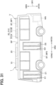
31 ist ein schematisches Schaubild eines Busfahrzeugs, in dem ein Klimatisierungssystem einer sechsten Ausführungsform angewandt wird.31 12 is a schematic diagram of a bus vehicle to which an air conditioning system of a sixth embodiment is applied. -
32 ist ein schematisches Gestaltungsschaubild des Klimatisierungssystems der sechsten Ausführungsform.32 12 is a schematic configuration diagram of the air conditioning system of the sixth embodiment. -
33 ist ein Ablaufdiagramm, das einen Ablaufprozess zeigt, der von einem Steuerungsgerät eines Klimatisierungssystems einer siebten Ausführungsform ausgeführt wird, wenn eine Vorrichtungstemperatursteuerung gestartet wird/ist.33 14 is a flowchart showing a flow process executed by a control apparatus of an air conditioning system of a seventh embodiment when device temperature control is started. -
34 ist ein Ablaufdiagramm, das einen Prozessablauf zeigt, der von dem Steuerungsgerät des Klimatisierungssystems der siebten Ausführungsform ausgeführt wird, wenn die Vorrichtungstemperatursteuerung gestoppt wird/ist.34 14 is a flowchart showing a flow of processing executed by the controller of the air conditioning system of the seventh embodiment when the device temperature control is stopped. -
35 ist ein schematisches Gestaltungsschaubild einer türseitigen Klimaanlage einer achten Ausführungsform.35 12 is a schematic configuration diagram of a door-side air conditioner of an eighth embodiment. -
36 ist ein schematisches Gestaltungsschaubild einer paneelseitigen Klimaanlage der achten Ausführungsform.36 12 is a schematic configuration diagram of a panel-side air conditioner of the eighth embodiment. -
37 ist ein Schaubild zur Erläuterung eines Druckverlusts der türseitigen Klimaanlage und der paneelseitigen Klimaanlage der achten Ausführungsform.37 12 is a diagram for explaining a pressure loss of the door-side air conditioner and the panel-side air conditioner of the eighth embodiment. -
38 ist ein Schaubild zur Erläuterung einer Modifikation der achten Ausführungsform.38 Fig. 14 is a diagram for explaining a modification of the eighth embodiment.
Beschreibung der AusführungsformenDescription of the embodiments
Nachfolgend werden Ausführungsformen der vorliegenden Offenbarung unter Bezugnahme auf die Zeichnungen beschrieben. In den folgenden Ausführungsformen sind Abschnitte, die mit den in den vorangegangenen Ausführungsformen beschriebenen Abschnitten identisch oder gleichwertig sind, mit denselben Bezugszeichen bezeichnet, und eine Beschreibung der gleichen oder gleichwertigen Abschnitte kann entfallen. Wenn in der Ausführungsform nur ein Teil der Komponenten beschrieben ist, können die in der vorangehenden Ausführungsform beschriebenen Komponenten auch auf andere Teile der Komponenten angewandt werden. Die folgenden Ausführungsformen können teilweise miteinander kombiniert werden, auch wenn eine derartige Kombination nicht explizit beschrieben ist, solange es keinen Nachteil in Bezug auf eine derartige Kombination gibt.Embodiments of the present disclosure will be described below with reference to the drawings. In the following embodiments, portions that are the same as or equivalent to portions described in the previous embodiments are denoted by the same reference numerals, and description of the same or equivalent portions may be omitted. When only a part of the components is described in the embodiment, the components described in the foregoing embodiment can also be applied to other parts of the components. The following embodiments may be partially combined with each other even if such a combination is not explicitly described as long as there is no disadvantage related to such a combination.
(Erste Ausführungsform)(First embodiment)
Die vorliegende Ausführungsform wird unter Bezugnahme auf die
Wie in den
Die Seitenfläche auf der rechten Seite in der Breitenrichtung DR3 des Busfahrzeugs V ist nicht mit der Fahrgasttür versehen, und die gesamte Seitenfläche auf der rechten Seite in der Breitenrichtung DR3 ist mit einem Seitenpaneel SP abgedeckt. Das Seitenpaneel SP ist ein Paneel, das die Seitenfläche des Busfahrzeugs V bildet. Als Ergebnis ist es möglich, an der linken Seite in der Breitenrichtung DR3 in das Busfahrzeug V ein- und auszusteigen. Zu beachten ist, dass in der vorliegenden Offenbarung ein Fenster, eine sich öffnende und schließende Tür für den Notausstieg und dergleichen, die an der Seitenfläche des Busfahrzeugs V festgelegt sind, einen Teil des Seitenpaneels SP bilden.The side surface on the right side in the width direction DR3 of the bus vehicle V is not provided with the passenger door, and the entire side surface on the right side in the width direction DR3 is covered with a side panel SP. The side panel SP is a panel that forms the side face of the bus vehicle V. As shown in FIG. As a result, it is possible to get on and off the bus vehicle V on the left side in the width direction DR3. Note that in the present disclosure, a window, an opening and closing door for emergency exit, and the like attached to the side face of the bus vehicle V form a part of the side panel SP.
Das Busfahrzeug V ist als ein Elektrofahrzeug gestaltet, das durch Verwendung von elektrischer Energie als eine Antriebsquelle fährt. Das Busfahrzeug V ist mit einem Fahrmotor MG und einer Batterie BT montiert, die elektrische Energie speichert, die dem Fahrmotor MG zugeführt werden kann.The bus vehicle V is designed as an electric vehicle that runs by using electric power as a drive source. The bus vehicle V is assembled with a traction motor MG and a battery BT that stores electric power that can be supplied to the traction motor MG.
Die Batterie BT weist einen Reihenschaltungskörper auf, in dem eine Vielzahl von Batteriezellen, die geladen und entladen werden können, elektrisch in Reihe geschaltet sind. Man beachte, dass in der Batterie BT einige der Vielzahl von Batteriezellen parallel geschaltet sein können.The battery BT has a series connection body in which a plurality of battery cells that can be charged and discharged are electrically connected in series. Note that in the battery BT, some of the plurality of battery cells may be connected in parallel.
Die Batterie BT ist mit einem nicht dargestellten Strominverter und dem Fahrmotor MG verbunden. Der Strominverter ist beispielsweise eine Vorrichtung, die einen von der Batterie BT gelieferten Gleichstrom in einen Wechselstrom umwandelt und den Wechselstrom an verschiedene elektrische Lasten wie zum Beispiel den Fahrmotor MG liefert.The battery BT is connected to an unillustrated power inverter and the traction motor MG. The power inverter is, for example, a device that converts a direct current supplied from the battery BT into an alternating current and supplies the alternating current to various electric loads such as the traction motor MG.
Die Batterie BT ist in einem Dachabschnitt (Deckenabschnitt) des Fahrzeugs V angeordnet. Insbesondere ist die Batterie BT auf einer Dachplatte RP des Fahrzeugs V installiert. Wenn die Batterie BT in dem Dachabschnitt angeordnet ist, wird die Bodenhöhe in dem Busfahrzeug V reduziert, und ein Fahrgast kann leicht in das Busfahrzeug V ein- und aussteigen.The battery BT is arranged in a roof portion (ceiling portion) of the vehicle V. FIG. Specifically, the battery BT is installed on a roof panel RP of the vehicle V. When the battery BT is arranged in the roof portion, the floor height in the bus vehicle V is reduced, and a passenger can get on and off the bus vehicle V easily.
Die Batterie BT ist eine Wärmeerzeugungsanlage, die an dem Busfahrzeug V montiert ist. Wenn sie während der Fahrt des Busfahrzeugs V die Stromversorgung oder ähnliches ausführt, erwärmt sich die Batterie BT von selbst, so dass die Temperatur der Batterie BT übermäßig hoch werden kann. Die Temperatur der Batterie BT kann auch beim Parken in dem Sommer oder dergleichen übermäßig hoch werden. Wenn die Temperatur der Batterie BT zu hoch wird, wird die Verschlechterung der Batteriezellen gefördert, so dass sich die Lebensdauer der Batterie deutlich verkürzt. Daher ist es notwendig, die Temperatur der Batterie BT so zu steuern, dass sie nicht zu hoch wird.The battery BT is heat generation equipment mounted on the bus vehicle V. FIG. When performing power supply or the like while the bus vehicle V is running, the battery BT self-heats, so the temperature of the battery BT may become excessively high. Also, the temperature of the battery BT may become excessively high when parking in the summer or the like. When the temperature of the battery BT becomes too high, the deterioration of the battery cells is promoted, so that the life of the battery is shortened significantly. Therefore, it is necessary to control the temperature of the battery BT not to become too high.
In Anbetracht dessen kann das Busfahrzeug V die Temperatur der Batterie BT durch den Einsatz von Geräten (Anlagen) zur Klimatisierung des Innenraums einstellen. Mit anderen Worten ist das Klimatisierungssystem 1 des Busfahrzeugs V so gestaltet, dass es nicht nur den Innenraum klimatisieren kann, sondern auch die Temperatur der Batterie BT als eine Zielanlage einstellen kann.In view of this, the bus vehicle V can adjust the temperature of the battery BT by using interior air conditioning devices (equipment). In other words, the
In dem Busfahrzeug V ist eine Vielzahl von Klimatisierungszonen Z in dem Innenraum des Busfahrzeugs V festgelegt, wie in
In dem Klimatisierungssystem 1 ist eine Vielzahl von Klimaanlagen 10 und 20 vorgesehen, die jeweils (zu) der Vielzahl von Klimatisierungszonen Z entsprechen (korrespondieren). Das heißt, in dem Klimatisierungssystem 1 ist die türseitige Klimaanlage 10 entsprechend der türseitigen Zone Zd und die paneelseitige Klimaanlage 20 entsprechend der paneelseitigen Zone Zp vorgesehen. Wie in
Die türseitige Klimaanlage 10 weist einen ersten Verdichter 11, einen ersten Kühler 12, ein erstes Innenexpansionsventil 13 und einen ersten Innenverdampfer 14 auf. Die paneelseitige Klimaanlage 20 weist einen zweiten Verdichter 21, einen zweiten Kühler 22, ein zweites Innenexpansionsventil 23, einen zweiten Innenverdampfer 24, ein zweites Anlagenexpansionsventil 25, einen zweiten Anlagenverdampfer 26, ein zweites kabinenseitiges Schaltventil 27 und ein zweites anlagenseitiges Schaltventil 28 auf.The door-
Der erste Verdichter 11 und der zweite Verdichter 21 sind Geräte (Anlagen), die ein Kältemittel verdichten und abgeben. Jeder der ersten Verdichter 11 und der zweiten Verdichter 21 weist einen elektrischen Verdichter auf, der einen Verdichtungsmechanismus mit einem Elektromotor antreibt. Die Kältemittelabgabeleistung des ersten Verdichters 11 und des zweiten Verdichters 21 wird gemäß einem Steuerungssignal von einem nachstehend beschriebenen Steuerungsgerät 100 ausgeführt.The first compressor 11 and the
Der erste Kühler 12 und der zweite Kühler 22 sind Geräte (Anlagen), die die Wärme des von dem ersten Verdichter 11 bzw. von dem zweiten Verdichter 21 abgegebenen Kältemittels nach außen abführen. Der erste Kühler 12 und der zweite Kühler 22 weisen jeweils Kondensationseinheiten 121 und 221, Flüssigkeitsaufnahmeeinheiten 122 und 222 und Unterkühlungsabschnitte 123 und 223 auf, so dass sich das Kältemittel auf den auslassseitigen Seiten in einem unterkühlten Zustand mit einem Unterkühlungsgrad befindet. Jede der Kondensationseinheiten 121 und 221 ist ein Wärmetauscher, der das Kältemittel kondensiert, indem er die Wärme des Kältemittels nach außen abführt. Die Flüssigkeitsaufnahmeeinheiten 122 und 222 sind Gas-Flüssigkeitsabscheider, die jeweils das Gas und die Flüssigkeit des Kältemittels, das die Kondensationseinheiten 121 und 221 durchlaufen hat, trennen und das in den Kreisläufen überschüssige Kältemittel speichern. Die Unterkühlungsabschnitte 123 und 223 sind Wärmetauscher, die das in den Flüssigkeitsaufnahmeeinheiten 122 und 222 gespeicherte flüssige Kältemittel entsprechend kühlen, indem sie dessen Wärme nach außen abführen.The
Das erste Innenexpansionsventil 13 und das zweite Innenexpansionsventil 23 sind Dekompressionseinheiten, die das Kältemittel, das den ersten Kühler 12 und den zweiten Kühler 22 durchlaufen hat, auf den gewünschten Druck dekomprimieren bzw. expandieren. Das erste Innenexpansionsventil 13 und das zweite Innenexpansionsventil 23 weisen jeweils thermische Expansionsventile auf, die jeweils die Öffnungen des ersten Innenverdampfers 14 und des zweiten Innenverdampfers 24 so einstellen, dass die Überhitzungsgrade auf der Auslassseite des Kältemittels der Verdampfer vorbestimmte Werte annehmen. Es ist zu beachten, dass sowohl das erste Innenexpansionsventil 13 als auch das zweite Innenexpansionsventil 23 ein elektrisches Expansionsventil aufweisen können, ohne auf ein mechanisches Expansionsventil beschränkt zu sein.The first
Der erste Innenverdampfer 14 und der zweite Innenverdampfer 24 sind Wärmetauscher, die das von dem ersten Innenexpansionsventil 13 bzw. dem zweiten Innenexpansionsventil 23 dekomprimierte Kältemittel verdampfen. Der erste Innenverdampfer 14 und der zweite Innenverdampfer 24 sind jeweils mit einem ersten Innenlüfter 141 und einem zweiten Innenlüfter 241 ausgestattet. Sowohl der erste Innenlüfter 141 als auch der zweite Innenlüfter 241 weist einen elektrischen Lüfter auf, der mit einem Elektromotor ein Laufrad (Lüfterrad) dreht.The first
Der erste Innenlüfter 141 ist ein Gebläse, das Luft in die türseitige Zone Zd bläst. Der erste Innenverdampfer 14 tauscht Wärme zwischen dem von dem ersten Innenexpansionsventil 13 dekomprimierten Kältemittel und der von dem ersten Innenlüfter 141 eingeblasenen Luft aus, um das Kältemittel zu verdampfen. Das heißt, der erste Innenverdampfer 14 nimmt Wärme aus der Luft auf, bevor sie in die türseitige Zone Zd geblasen wird, um das Kältemittel zu verdampfen. Als Ergebnis wird die durch den ersten Innenverdampfer 14 gekühlte und entfeuchtete Luft in Richtung der türseitigen Zone Zd ausgeblasen.The first
Der zweite Innenlüfter 241 ist ein Gebläse, das Luft in die paneelseitige Zone Zp bläst. Der zweite Innenverdampfer 24 tauscht Wärme zwischen dem von dem zweiten Innenexpansionsventil 23 dekomprimierten Kältemittel und der von dem zweiten Innenlüfter 241 eingeblasenen Luft aus, um das Kältemittel zu verdampfen. Das heißt, der zweite Innenverdampfer 24 nimmt Wärme aus der Luft auf, bevor sie in die paneelseitige Zone Zp geblasen wird, um das Kältemittel zu verdampfen. Als Ergebnis wird die durch den zweiten Innenverdampfer 24 gekühlte und entfeuchtete Luft in Richtung der paneelseitigen Zone Zp ausgeblasen.The second
Hier ist die paneelseitige Klimaanlage 20 mit dem zweiten Anlagenexpansionsventil 25 und dem zweiten Anlagenverdampfer 26 versehen. Das zweite Anlagenexpansionsventil 25 und der zweite Anlagenverdampfer 26 sind parallel zu dem zweiten Innenexpansionsventil 23 und dem zweiten Innenverdampfer 24 in Bezug auf eine Kältemittelströmung angeordnet.Here, the panel-
Das zweite Anlagenexpansionsventil 25 ist eine Dekompressionseinheit, die das Kältemittel, das den zweiten Kühler 22 durchströmt hat, auf einen gewünschten Druck dekomprimiert und expandiert. Das zweite Anlagenexpansionsventil 25 ist in einem Kältemittelrohr vorgesehen, das von einem Kältemittelrohr abzweigt, die den zweiten Kühler 22 und das zweite Innenexpansionsventil 23 verbindet. Das zweite Anlagenexpansionsventil 25 ist in Bezug auf die Strömung des Kältemittels parallel zu dem zweiten Innenexpansionsventil 23 angeordnet. Das zweite Anlagenexpansionsventil 25 weist ein thermisches Expansionsventil auf, das eine Öffnung des zweiten Anlagenverdampfers 26 so einstellt, dass ein Überhitzungsgrad auf der Auslassseite des Kältemittels an dem Verdampfer einen vorbestimmten Wert annimmt. Es ist zu beachten, dass das zweite Expansionsventil 25 ein elektrisches Expansionsventil aufweisen kann, ohne auf ein mechanisches Expansionsventil beschränkt zu sein.The second
Der zweite Anlagenverdampfer 26 ist ein Chiller (Kühler), der das von dem zweiten Anlagenexpansionsventil 25 dekomprimierte Kältemittel verdampft. Der zweite Anlagenverdampfer 26 weist einen Kältemittelströmungsweg 261 auf, durch den das von dem zweiten Anlagenexpansionsventil 25 dekomprimierte Kältemittel strömen kann, sowie einen Wärmemediumströmungsweg 262, durch den ein in einem nachstehend beschriebenen Kühlkreislauf 31 zirkulierendes Wärmemedium strömen kann.The
Der zweite Anlagenverdampfer 26 tauscht Wärme zwischen dem Kältemittel, das durch den Kältemittelströmungsweg 261 strömt, und dem Kältemittelströmungsweg 262 aus, um das Kältemittel zu verdampfen. Das durch den Kältemittelströmungsweg 262 strömende Wärmemedium wird mit der Wärme gekühlt, die das durch den Kältemittelströmungsweg 261 strömende Kältemittel aufgenommen wird.The second system evaporator 26 exchanges heat between the refrigerant flowing through the
Auf der Kältemittelauslassseite eines von dem zweiten Innenverdampfer 24 und dem zweiten Anlagenverdampfer 26 ist ein nicht dargestelltes Verdampfungsdruckregelventil zur Regelung des Drucks in dem einen Verdampfer auf einen gewünschten Druck vorgesehen. Als Ergebnis können die Drücke des Kältemittels in dem zweiten Innenverdampfer 24 und dem zweiten Anlagenverdampfer 26 gemäß den jeweiligen thermischen Lasten eingestellt werden.On the refrigerant outlet side of one of the second
Die paneelseitige Klimaanlage 20 ist mit dem zweiten kabinenseitigen Schaltventil 27 und dem zweiten anlageseitigen Schaltventil 28 versehen. Das zweite kabinenseitige Schaltventil 27 und das zweite anlagenseitige Schaltventil 28 arbeiten als ein Strömungswegumschaltventil, das den Strömungsweg des Kältemittels, das den zweiten Kühler 22 durchlaufen hat, umschaltet. Das zweite kabinenseitige Schaltventil 27 und das zweite anlagenseitige Schaltventil 28 sind jeweils ein Solenoidventil und werden gemäß einem Steuerungssignal des nachstehend beschriebenen Steuerungsgeräts 100 gesteuert.The panel-
Das zweite kabinenseitige Schaltventil 27 ist in einem Kältemittelrohr vorgesehen, das das Kältemittel, das den zweiten Kühler 22 durchlaufen hat, zu dem zweiten Innenexpansionsventil 23 führt. Das zweite kabinenseitige Schaltventil 27 ist eine Schalteinheit, die zwischen einem Zustand, in dem die Strömung des Kältemittels zu dem zweiten Innenverdampfer 24 zugelassen wird, und einem Zustand, in dem die Strömung des Kältemittels zu dem zweiten Innenverdampfer 24 blockiert wird, umschaltet.The second cabin-
Das zweite anlagenseitige Schaltventil 28 ist in einem Kältemittelrohr vorgesehen, das das Kältemittel, das den zweiten Kühler 22 passiert hat, zu dem zweiten Anlagenexpansionsventil 25 führt. Das zweite anlagenseitige Schaltventil 28 ist eine türseitige Schalteinheit, die zwischen einem zweiten erlaubten Zustand, in dem die Strömung des Kältemittels zu dem zweiten Anlagenverdampfer 26 erlaubt ist, und einem zweiten blockierten Zustand, in dem die Strömung des Kältemittels zu dem zweiten Anlagenverdampfer 26 blockiert ist, umschaltet.The second facility-
Andererseits weist die türseitige Klimaanlage 10 nur den ersten Innenverdampfer 14 auf, der Wärme aus der in den Innenraum ausblasenden Luft aufnimmt, aber keine Wärmeaufnahmevorrichtung, die Wärme aus dem Wärmemedium erwärmt. Das heißt, die türseitige Klimaanlage 10 ist nicht mit Gestaltungen versehen, die dem zweiten Anlagenexpansionsventil 25 und dem zweiten Anlagenverdampfer 26 entsprechen.On the other hand, the door-
Das Klimatisierungssystem 1 ist mit einem Kühler 30 versehen, der den vorstehenden Kühlkreislauf 31 aufweist. Der Kühler 30 kühlt die Batterie BT als die Zielanlage. Der Kühler 30 stellt die Temperatur der Batterie BT durch Kühlen des Wärmemediums unter Ausnutzung einer endothermen Wirkung in einem Teil der Vielzahl der Klimaanlagen 10 und 20 ein. Als das Wärmemedium kann zum Beispiel ein Frostschutzmittel, das Ethylenglykol und ähnliches enthält, verwendet werden.The
Der Kühler 30 weist den Kühlkreislauf 31 auf, in dem das Wärmemedium zirkuliert. Der Kühlkreislauf 31 ist mit einer Zirkulationspumpe 32, dem Wärmemediumströmungsweg 262 des zweiten Anlagenverdampfers 26, einem Dreiwegeventil 33, einer Batteriekühleinheit 34 und einem Radiator 35 versehen.The cooler 30 has the
Die Zirkulationspumpe 32 ist eine elektrische Pumpe, die das Wärmemedium in den Wärmemediumströmungsweg 262 des zweiten Anlagenverdampfers 26 pumpt. Die Pumpleistung der Zirkulationspumpe 32 wird gemäß einem Steuerungssignal des nachstehend beschriebenen Steuerungsgeräts 100 gesteuert.The
Ein Einlass des Dreiwegeventils 33 ist mit einer Auslassseite des Wärmemediumströmungswegs 262 des zweiten Anlagenverdampfers 26 verbunden. Das Dreiwegeventil 33 ist ein elektrisches Dreiwegeventil zur Regelung der Strömung, das einen Einlass und zwei Auslässe hat und die beiden Auslässe wahlweise öffnen und schließen kann. Das Dreiwegeventil 33 wird gemäß einem Steuerungssignal von dem nachstehend beschriebenen Steuerungsgerät 100 gesteuert.An inlet of the three-
Ein Einlass der Batteriekühleinheit 34 ist mit einer der Auslassseiten des Dreiwegeventils 33 verbunden. Die Batteriekühleinheit 34 hat eine Vielzahl von Wärmeaustauschströmungswegen, die so angeordnet sind, dass sie in Kontakt mit einer Vielzahl von Batteriezellen stehen, die die Batterie BT bilden. Die Batteriekühleinheit 34 kühlt die Batterie BT durch Austauschen von Wärme zwischen dem Wärmemedium, das durch die Wärmeaustauschströmungswege strömt, und den Batteriezellen.An inlet of the
Eine derartige Batteriekühleinheit 34 kann dadurch realisiert werden, dass die Wärmeaustauschströmungswege zwischen den benachbarten Batteriezellen angeordnet werden. Man beachte, dass die Batteriekühleinheit 34 einstückig mit der Batterie BT ausgebildet sein kann, indem Wärmeaustauschströmungswege in einem Gehäuse vorgesehen werden, das die Batteriezellen aufnimmt.Such a
Ein Einlass des Radiators 35 ist mit der anderen der Auslassseiten des Dreiwegeventils 33 verbunden. Der Radiator 35 ist ein Wärmetauscher, der die Wärme des Wärmemediums, das den zweiten Anlagenverdampfer 26 durchlaufen hat, durch Austauschen von Wärme mit der Außenluft abführt.An inlet of the
Die Batteriekühleinheit 34 und der Radiator 35 sind über einen Zusammenführungsabschnitt, der an den Auslassseiten der Batteriekühleinheit 34 und des Radiators 35 vorgesehen ist, mit einem Sauganschluss der Zirkulationspumpe 32 verbunden. Die Batteriekühleinheit 34 und der Radiator 35 sind in Bezug auf eine Strömung des Wärmemediums parallel geschaltet.The
Als nächstes wird das Steuerungsgerät 100, eine elektronische Steuerungseinheit des Klimatisierungssystems 1, beschrieben. Das Steuerungsgerät 100 weist einen Computer mit einem Prozessor und einem Speicher sowie Peripherieschaltungen auf. Das Steuerungsgerät 100 führt auf der Grundlage von in dem Speicher gespeicherten Programmen verschiedene Berechnungen und Verarbeitungen aus und steuert Geräte (Anlagen), die mit einer Ausgangsseite des Geräts verbunden sind. Der Speicher des Steuerungsgeräts 100 weist ein nicht flüchtiges konkretes Speichermedium auf.Next, the
An eine Ausgangsseite des Steuerungsgeräts 100 sind der erste Verdichter 11, der erste Innenlüfter 141, der zweite Verdichter 21, der zweite Innenlüfter 241, das zweite kabinenseitige Schaltventil 27, das zweite anlagenseitige Schaltventil 28, die Zirkulationspumpe 32, das Dreiwegeventil 33 und dergleichen angeschlossen. Software und Hardware des Steuerungsgeräts 100 zur Steuerung der türseitigen Klimaanlage 10 und der paneelseitigen Klimaanlage 20 bilden in der vorliegenden Ausführungsform eine Klimatisierungssteuerungseinheit 100a.On an output side of the
In dem Steuerungsgerät 100 ist eine Gruppe von Sensoren 101 zur Steuerung der Klimaanlage und zur Steuerung der Temperatur der Batterie mit einer Seite des Steuerungsgeräts 100 verbunden. Die Gruppe von Sensoren 101 weist einen Innenlufttemperatursensor, einen Außenlufttemperatursensor, einen Sonnenstrahlungssensor, PT-Sensoren, die jeweils Drücke und Temperaturen auf der Kältemittelauslassseite der Verdampfer 14, 24 und 26 erfassen, einen Batterietemperatursensor, der die Temperatur der Batterie BT erfasst, und dergleichen auf. Erfassungssignale der Gruppe von Sensoren 101 werden in das Steuerungsgerät 100 eingegeben. Als Ergebnis kann das Klimatisierungssystem 1 die Temperatur der in den Innenraum eingeblasenen Luft, die Temperatur der Batterie BT und dergleichen gemäß den von der Gruppe der Sensoren 101 erfassten physikalischen Größen einstellen.In the
Darüber hinaus ist ein Bedienfeld 102, das für verschiedene Eingabevorgänge verwendet werden kann, mit der Eingangsseite des Steuerungsgeräts 100 verbunden. Das Bedienfeld 102 ist in der Nähe einer Instrumententafel angeordnet und weist verschiedene Betriebsschalter auf. Betriebssignale von den verschiedenen Betriebsschaltern, die auf dem Bedienfeld 102 vorgesehen sind, werden in das Steuerungsgerät 100 eingegeben.In addition, a
Die verschiedenen Betriebsschalter des Bedienfelds 102 weisen einen Autoschalter, einen Betriebsmodus-Umschalter, einen Luftmengen-Einstellschalter, einen Temperatur-Einstellschalter, einen Blasmodus-Umschalter und dergleichen auf. Das Klimatisierungssystem 1 kann die Betriebsmodi des Klimatisierungssystems 1 entsprechend umschalten, indem es eine Eingabe an dem Bedienfeld 102 erhält. Insbesondere schaltet das Steuerungsgerät 100 die Betriebsmodi des Klimatisierungssystems 1 durch Steuern des zweiten kabinenseitigen Schaltventils 27 und des zweiten anlagenseitigen Schaltventils 28 um, um die Strömung des Kältemittels in der paneelseitigen Klimaanlage 20 zu ändern.The various operation switches of the
Im Folgenden wird der Betrieb des Klimatisierungssystems 1 beschrieben. Das Klimatisierungssystem 1 ist so gestaltet, dass es als seine Betriebsmodi eine Innenraumkühlung (Innenraumkühlen, Innenkühlung) und eine Anlagentemperatursteuerung ausführen kann. Die Innenraumkühlung ist ein Betriebsmodus, in dem der Innenraum durch die türseitige Klimaanlage 10 und die paneelseitige Klimaanlage 20 gekühlt wird. Die Anlagentemperatursteuerung ist ein Betriebsmodus, in dem die Innenraumkühlung und die Temperatursteuerung der Batterie BT entsprechend von der türseitigen Klimaanlage 10 und der paneelseitigen Klimaanlage 20 ausgeführt werden können. Der Betrieb des Klimatisierungssystems 1 für die Innenraumkühlung und die Anlagentemperatursteuerung wird in dem Folgenden beschrieben.The operation of the
<Innenraumkühlung><Interior cooling>
Die Innenraumkühlung ist ein Betriebsmodus, in dem die durch den ersten Innenverdampfer 14 und den zweiten Innenverdampfer 24 auf eine gewünschte Temperatur gekühlte Luft in den Innenraum des Busfahrzeugs V ausgeblasen wird. Die Innenraumkühlung wird von dem Klimatisierungssystem 1 zum Beispiel ausgeführt, wenn der Betriebsmodus durch den Betriebsmodus-Umschalter auf einen Kühlmodus festgelegt ist.The interior cooling is an operation mode in which the air cooled to a desired temperature by the first
Das Steuerungsgerät 100 bestimmt durch Verwendung der Erfassungssignale der Gruppe von Sensoren 101 und der Betriebssignale des Bedienfeldes 102 in geeigneter Weise Betriebszustände verschiedener Geräte (Anlagen) während der Innenraumkühlung. Zum Beispiel steuert das Steuerungsgerät 100 die jeweiligen Schaltventile 17 und 18 so, dass das zweite kabinenseitige Schaltventil 27 geöffnet und das zweite anlagenseitige Schaltventil 28 geschlossen wird. Das Steuerungsgerät 100 bestimmt durch Verwendung der Erfassungssignale der Gruppe von Sensoren 101 und der Betriebssignale des Bedienfelds 102 in geeigneter Weise Steuerungssignale für andere Geräte (Anlagen), wie zum Beispiel die jeweiligen Verdichter 11 und 21 und die jeweiligen Innenlüfter 141 und 241.The
In der türseitigen Klimaanlage 10 strömt das von dem ersten Verdichter 11 abgegebene Hochdruckkältemittel während der Innenraumkühlung in die Kondensationseinheit 121 des ersten Kühlers 12 und gibt (führt) Wärme ab. Das Kältemittel, das die Kondensationseinheit 121 passiert hat, strömt in die Flüssigkeitsaufnahmeeinheit 122 und wird dort in Gas und Flüssigkeit getrennt (abgeschieden). Das in der Flüssigkeitsaufnahmeeinheit 122 getrennte (abgeschiedene) flüssige Kältemittel strömt in den Unterkühlungsabschnitt 123 und gibt Wärme ab.In the door-
Das aus dem Unterkühlungsabschnitt 123 strömende Kältemittel strömt in das erste Innenexpansionsventil 13 und wird durch das erste Innenexpansionsventil 13 auf einen gewünschten Druck dekomprimiert. Das durch das erste Innenexpansionsventil 13 dekomprimierte Kältemittel strömt in den ersten Innenverdampfer 14.The refrigerant flowing out of the
Das Kältemittel, das in den ersten Innenverdampfer 14 geströmt ist, nimmt Wärme von der eingeblasenen Luft des ersten Innenlüfters 141 auf und verdampft. Das heißt, das Kältemittel, das in den ersten Innenverdampfer 14 geströmt ist, nimmt Wärme aus der Luft auf, bevor es zu der türseitigen Zone Zd ausgeblasen wird, und verdampft. Als Ergebnis wird die durch den ersten Innenverdampfer 14 auf eine gewünschte Temperatur gekühlte Luft zu der türseitigen Zone Zd ausgeblasen.The refrigerant that has flown into the first
Das Kältemittel, das den ersten Innenverdampfer 14 durchlaufen hat, wird in den ersten Verdichter 11 gesaugt. Das Kältemittel, das in den ersten Verdichter 11 gesaugt wurde, wird durch den ersten Verdichter 11 verdichtet, bis das Kältemittel wieder ein Hochdruckkältemittel wird/ist.The refrigerant that has passed through the first
In der paneelseitigen Klimaanlage 20 strömt das aus dem zweiten Verdichter 21 abgegebene Hochdruckkältemittel hingegen in die Kondensationseinheit 221 des zweiten Kühlers 22 und gibt, ähnlich wie bei der türseitigen Klimaanlage 10, Wärme ab. Das Kältemittel, das die Kondensationseinheit 221 passiert hat, strömt in die Flüssigkeitsaufnahmeeinheit 222, wo es in Gas und Flüssigkeit getrennt (abgeschieden) wird. Das in der Flüssigkeitsaufnahmeeinheit 222 getrennte flüssige Kältemittel strömt in den Unterkühlungsabschnitt 223 und gibt Wärme ab.On the other hand, in the panel-
Das Kältemittel, das aus dem Unterkühlungsabschnitt 223 geströmt ist, strömt in das zweite Innenexpansionsventil 23 und wird durch das zweite Innenexpansionsventil 23 auf einen gewünschten Druck dekomprimiert. Während der Innenraumkühlung ist das zweite anlagenseitige Schaltventil 28 geschlossen, so dass das Kältemittel nicht in das zweite anlagenseitige Expansionsventil 25 strömt, und das gesamte Kältemittel wird durch das zweite Innenexpansionsventil 23 dekomprimiert.The refrigerant that has flowed out of the
Das durch das zweite Innenexpansionsventil 23 dekomprimierte Kältemittel strömt in den zweiten Innenverdampfer 24. Das Kältemittel, das in den zweiten Innenverdampfer 24 geströmt ist, nimmt Wärme von der von dem zweiten Innenlüfter 241 eingeblasenen Luft auf und verdampft. Das heißt, das Kältemittel, das in den zweiten Innenverdampfer 24 geströmt ist, nimmt Wärme aus der Luft auf, bevor es in die paneelseitige Zone Zp ausgeblasen wird, und verdampft. Als Ergebnis wird die durch den zweiten Innenverdampfer 24 auf eine gewünschte Temperatur gekühlte Luft zu der paneelseitigen Zone Zp ausgeblasen.The refrigerant decompressed by the second
Das Kältemittel, das den zweiten Innenverdampfer 24 durchlaufen hat, wird in den zweiten Verdichter 21 gesaugt. Das Kältemittel, das in den zweiten Verdichter 21 gesaugt wurde, wird durch den zweiten Verdichter 21 verdichtet, bis das Kältemittel wieder ein Hochdruckkältemittel wird/ist.The refrigerant that has passed through the second
Während der Innenraumkühlung wird die durch den ersten Innenverdampfer 14 gekühlte Luft in die türseitige Zone Zd ausgeblasen und wird die durch den zweiten Innenverdampfer 24 gekühlte Luft in die paneelseitige Zone Zp ausgeblasen, wie vorstehend beschrieben ist. Als Ergebnis wird eine Innenraumkühlung realisiert.During the interior cooling, the air cooled by the first
<Anlagentemperatursteuerung><System Temperature Control>
Die Anlagentemperatursteuerung ist ein Betriebsmodus, in dem, während die durch den ersten Innenverdampfer 14 und den zweiten Innenverdampfer 24 auf eine gewünschte Temperatur gekühlte Luft in den Innenraum des Fahrzeugs V ausgeblasen wird, die Temperatur der Batterie BT als die Zielanlage durch Ausnutzung der latenten Verdampfungswärme des Kältemittels eingestellt wird. Die Anlagentemperatursteuerung wird von dem Klimatisierungssystem 1 beispielsweise dann ausgeführt, wenn die Temperatur der Batterie BT in einem Zustand, in dem der Autoschalter eingeschaltet ist, die obere Grenze einer geeigneten Temperatur überschreitet. Es ist zu beachten, dass die Bedingung für die Ausführung der Anlagentemperatursteuerung von der vorstehend beschriebenen Bedingung abweichen kann.The facility temperature control is an operation mode in which, while the air cooled to a desired temperature by the first
Das Steuerungsgerät 100 bestimmt in geeigneter Weise die Betriebszustände verschiedener Geräte (Anlagen) während der Anlagentemperatursteuerung durch Verwendung der Erfassungssignale der Gruppe von Sensoren 101 und der Betriebssignale des Bedienfelds 102. Zum Beispiel steuert das Steuerungsgerät 100 die jeweiligen Schaltventile 27 und 28 so, dass das zweite kabinenseitige Schaltventil 27 und das zweite anlagenseitige Schaltventil 28 jeweils geöffnet werden. Das Steuerungsgerät 100 steuert das Dreiwegeventil 33 so, dass das gesamte Wärmemedium, das den Wärmemediumströmungsweg 262 des zweiten Anlagenverdampfers 26 durchlaufen hat, in die Batteriekühleinheit 34 strömt. Das Steuerungsgerät 100 bestimmt durch Verwendung der Erfassungssignale der Gruppe von Sensoren 101 und der Betriebssignale des Bedienfelds 102 in geeigneter Weise Steuerungssignale für andere Geräte (Anlagen), wie zum Beispiel der jeweiligen Verdichter 11 und 21, der jeweiligen Innenlüfter 141 und 241 und der Zirkulationspumpe 32.The
Während der Anlagenkühlung strömt das von dem ersten Verdichter 11 abgegebene Hochdruckkältemittel in den ersten Kühler 12 und gibt Wärme in der türseitigen Klimaanlage 10 ab, ähnlich wie bei der Innenraumkühlung. Das Kältemittel, das aus dem Kühler 12 strömt, strömt in das erste Innenexpansionsventil 13.During system cooling, the high-pressure refrigerant discharged from the first compressor 11 flows into the
Das Kältemittel, das in das erste Innenexpansionsventil 13 geströmt ist, wird durch das erste Innenexpansionsventil 13 auf einen gewünschten Druck dekomprimiert und strömt dann in den ersten Innenverdampfer 14. Das Kältemittel, das in den ersten Innenverdampfer 14 geströmt ist, nimmt Wärme von der von dem ersten Innenlüfter 141 eingeblasenen Luft auf und verdampft. Als Ergebnis wird die durch den ersten Innenverdampfer 14 auf eine gewünschte Temperatur gekühlte Luft zu der türseitigen Zone Zd ausgeblasen.The refrigerant that has flowed into the first
Das Kältemittel, das den ersten Innenverdampfer 14 durchlaufen hat, wird in den ersten Verdichter 11 gesaugt. Das Kältemittel, das in den ersten Verdichter 11 gesaugt wurde, wird durch den ersten Verdichter 11 verdichtet, bis das Kältemittel wieder ein Hochdruckkältemittel wird/ist.The refrigerant that has passed through the first
In der paneelseitigen Klimaanlage 20 strömt dagegen das von dem zweiten Verdichter 21 abgegebene Hochdruckkältemittel in den zweiten Kühler 22 und gibt Wärme ab, ähnlich wie bei der Innenraumkühlung. Das Kältemittel, das aus dem zweiten Kühler 22 geströmt ist, strömt in das zweite Innenexpansionsventil 23 und das zweite Anlagenexpansionsventil 25.On the other hand, in the panel-
Das Kältemittel, das in das zweite Innenexpansionsventil 23 geströmt ist, wird durch das zweite Innenexpansionsventil 23 auf einen gewünschten Druck dekomprimiert. Das durch das zweite Innenexpansionsventil 23 dekomprimierte Kältemittel strömt in den zweiten Innenverdampfer 24.The refrigerant that has flown into the second
Das Kältemittel, das in den zweiten Innenverdampfer 24 geströmt ist, nimmt Wärme von der eingeblasenen Luft des zweiten Innenlüfters 241 auf und verdampft. Das heißt, das Kältemittel, das in den zweiten Innenverdampfer 24 geströmt ist, nimmt Wärme aus der Luft auf, bevor es in die paneelseitige Zone Zp ausgeblasen wird, und verdampft. Als Ergebnis wird die durch den zweiten Innenverdampfer 24 auf eine gewünschte Temperatur gekühlte Luft in die paneelseitige Zone Zp ausgeblasen.The refrigerant that has flown into the second
Andererseits wird das Kältemittel, das in das zweite Anlagenexpansionsventil 25 geströmt ist, durch das zweite Anlagenexpansionsventil 25 auf einen gewünschten Druck dekomprimiert und strömt dann in den zweiten Anlagenverdampfer 26. Das Kältemittel, das in den zweiten Anlagenverdampfer 26 geströmt ist, nimmt Wärme von dem Wärmemedium auf, das in dem Kühlkreislauf 31 strömt, und verdampft. Als Ergebnis wird das in dem Kühlkreislauf 31 strömende Wärmemedium gekühlt, wenn es den Wärmemediumströmungsweg 262 des zweiten Anlagenverdampfers 26 durchläuft.On the other hand, the refrigerant that has flowed into the second
Das Kältemittel, das den zweiten Innenverdampfer 24 durchlaufen hat, und das Kältemittel, das den zweiten Anlagenverdampfer 26 durchlaufen hat, werden in den zweiten Verdichter 21 gesaugt. Das Kältemittel, das in den zweiten Verdichter 21 gesaugt wurde, wird durch den zweiten Verdichter 21 verdichtet, bis das Kältemittel wieder ein Hochdruckkältemittel wird/ist.The refrigerant that has passed through the second
Dabei strömt das durch den zweiten Anlagenverdampfer 26 gekühlte Wärmemedium zu der Batteriekühleinheit 34 und nimmt Wärme von der Batterie BT auf. Als Ergebnis wird die Batterie BT gekühlt. Das heißt, während der Anlagentemperatursteuerung wird die Batterie BT durch Ausnutzung einer endothermen Wirkung aufgrund der Verdampfung des Kältemittels in dem zweiten Anlagenverdampfer 26 gekühlt.At this time, the heat medium cooled by the
Während der Anlagentemperatursteuerung wird die von den jeweiligen Innenverdampfern 14 und 24 gekühlte Luft zu den jeweiligen Zonen Zd und Zp ausgeblasen und wird das von dem zweiten Anlagenverdampfer 26 gekühlte Wärmemedium, wie vorstehend beschrieben, zu der Batteriekühleinheit 34 zugeführt. Als Ergebnis werden die Kühlung des Innenraums und die Kühlung der Batterie BT realisiert.During the facility temperature control, the air cooled by the respective
Das vorstehend beschriebene Klimatisierungssystem 1 ist so gestaltet, dass es den Innenraum des Fahrzeugs V in eine Vielzahl von Klimatisierungszonen Z unterteilt und die Klimatisierung der Vielzahl von Klimatisierungszonen Z durch eine Vielzahl von Klimaanlagen 10 und 20 ausführt, die vorgesehen sind, um jeweils der Vielzahl von Klimatisierungszonen Z zu entsprechen. Insbesondere sind in dem Busfahrzeug V eine oder mehrere Türen D an der Seitenfläche auf einer Seite in der Breitenrichtung DR3 vorgesehen, das Seitenpaneel SP ist auf der Seitenfläche auf der anderen Seite in der Breitenrichtung vorgesehen, die türseitige Zone Zd ist auf einer Seite in der Breitenrichtung DR3 festgelegt, und die paneelseitige Zone Zp ist auf der anderen Seite in der Breitenrichtung DR3 festgelegt. Demgemäß kann für jede der Klimatisierungszonen Z geeignet klimatisierte Luft bereitgestellt werden, so dass ein Komfort in dem Innenraum gewährleistet werden kann.The
Dabei hat von den Klimatisierungszonen Z die türseitige Zone Zd in der Nähe der Türen D1 und D2 des Busfahrzeugs V mit geringerer Wahrscheinlichkeit eine niedrigere Temperatur als die von den Türen D1 und D2 des Busfahrzeugs V entfernte paneelseitige Zone Zp, da in der türseitigen Zone Zd eher ein Belüftungsverlust durch das Öffnen und Schließen der Türen D1 und D2 auftritt.Here, of the air-conditioning zones Z, the door-side zone Zd near the doors D1 and D2 of the bus vehicle V is less likely to have a lower temperature than the panel-side zone Zp distant from the doors D1 and D2 of the bus vehicle V because the door-side zone Zd is more likely there is a loss of ventilation due to the opening and closing of doors D1 and D2.
In Anbetracht dessen weist die paneelseitige Klimaanlage 20 den zweiten Anlagenverdampfer 26 auf und weist die türseitige Klimaanlage 10 in dem Klimatisierungssystem 1 der vorliegenden Ausführungsform keine Wärmeaufnahmevorrichtung auf, die Wärme von dem Wärmemedium aufnimmt. In einer derartigen Gestaltung ist die Menge der Wärme, die von dem Wärmemedium während der Anlagentemperatursteuerung aufgenommen wird, in der türseitigen Klimaanlage 10 geringer (kleiner) als in der paneelseitigen Klimaanlage 20, wie in
Da die türseitige Klimaanlage 10 während der Anlagentemperatursteuerung keine Wärme von dem Wärmemedium aufnimmt, erhöht sich die Wärmemenge, die von der zu der türseitigen Zone Zd ausgeblasen Luft. Als Ergebnis kann die Temperatur der türseitigen Zone Zd ausreichend gesenkt werden. Das heißt, die türseitige Klimaanlage 10 kann die endotherme Wirkung des Kältekreislaufs RC1 auf die zu der türseitigen Zone Zd ausgeblasene Luft konzentrieren. Daher kann, auch wenn die Batterie BT gekühlt wird, der Komfort in der türseitigen Zone Zd in der Nähe der Türen D1 und D2 des Busfahrzeugs V gewährleistet werden. Das heißt, dass es gemäß dem Klimatisierungssystem 1 möglich ist, den Komfort in der Klimatisierungszone Z zu gewährleisten, in der es leicht zu Belüftungsverlusten aufgrund des Öffnens und Schließens der Plattformen E1 und E2 durch die Fahrgasttüren kommt.Since the door-
(Modifikation der ersten Ausführungsform)(Modification of the first embodiment)
In der ersten Ausführungsform hat das Busfahrzeug V beispielhaft die Plattformen E1 und E2 und die Türen D1 und D2 an zwei Stellen des vorderen Abschnitts und des mittleren Abschnitts der Seitenfläche auf der linken Seite in der Breitenrichtung DR3 angeordnet. Das Busfahrzeug V ist jedoch nicht darauf beschränkt.In the first embodiment, for example, the bus vehicle V has the platforms E1 and E2 and the doors D1 and D2 arranged at two locations of the front portion and the middle portion of the side surface on the left side in the width direction DR3. However, the bus vehicle V is not limited to this.
Das Busfahrzeug V kann beispielsweise mit einer Tür an der Seitenfläche auf einer Seite in der Breitenrichtung DR3 und dem Seitenpaneel SP an der Seitenfläche auf der anderen Seite versehen sein. Insbesondere kann das Busfahrzeug V mit der Plattform E1 und der Tür D1 an einer Stelle des vorderen Abschnitts der Seitenfläche auf der linken Seite in Breitenrichtung DR3 versehen sein, wie in
Das Busfahrzeug V kann beispielsweise mit einer oder mehreren Türen an den vorderen oder hinteren Seitenflächen auf beiden Seiten in der Breitenrichtung DR3 und mit den Seitenpaneelen SP auf den anderen Seiten versehen sein. Insbesondere kann das Busfahrzeug V mit den Plattformen E1 und E2 und den Türen D1 und D2 an zwei Stellen der vorderen Abschnitte der Seitenflächen auf beiden Seiten in Breitenrichtung DR3 versehen sein, wie in
(Zweite Ausführungsform)(Second embodiment)
Nachfolgend wird eine zweite Ausführungsform unter Bezugnahme auf
In der vorliegenden Ausführungsform wird ein Beispiel beschrieben, in dem das Klimatisierungssystem 1 bei dem Busfahrzeug V angewandt wird, in dem die Klimatisierungszonen Z an vier Stellen des Innenraums vorne, hinten, links und rechts angeordnet sind. Wie in
Die Klimatisierungssystem 1 ist mit einer ersten türseitigen Klimaanlage 10A, einer zweiten türseitigen Klimaanlage 10B, einer ersten paneelseitigen Klimaanlage 20A und einer zweiten paneelseitigen Klimaanlage 20B versehen, die jeweils den vier Klimatisierungszonen Z entsprechen. Jede der türseitigen Klimaanlagen 10A und 10B ist ähnlich gestaltet wie die in der ersten Ausführungsform beschriebene türseitige Klimaanlage 10. Jede der paneelseitigen Klimaanlagen 20A und 20B ist ebenfalls ähnlich gestaltet wie die in der ersten Ausführungsform beschriebene paneelseitige Klimaanlage 20.The
Andere Gestaltungen sind gleich wie die der ersten Ausführungsform. Die Klimatisierungssystem 1 der vorliegenden Ausführungsform kann Wirkungen erhalten, die von einer Gestaltung ausgehen, die derjenigen der ersten Ausführungsform ähnlich oder gleichwertig ist, ähnlich wie bei der ersten Ausführungsform.Other configurations are the same as those of the first embodiment. The
Da die Klimatisierungszonen Z an vier Stellen des vorderen, hinteren, linken und rechten Innenraums angeordnet sind, kann das Klimatisierungssystem 1 der vorliegenden Ausführungsform klimatisierte Luft bereitstellen, die für die jeweiligen Räume des vorderen, hinteren, linken und rechten Innenraums geeignet ist. Als Ergebnis kann der Komfort in dem Innenraum ausreichend gewährleistet werden.Since the air conditioning zones Z are arranged at four locations of the front, rear, left, and right cabins, the
(Modifikation der zweiten Ausführungsform)(Modification of the second embodiment)
In der zweiten Ausführungsform ist das Busfahrzeug V vorgesehen, in dem beispielhaft die Plattformen E1 und E2 und die Türen D1 und D2 an zwei Stellen des vorderen Abschnitts und des mittleren Abschnitts der Seitenfläche auf der linken Seite in der Breitenrichtung DR3 angeordnet sind. Das Busfahrzeug V ist jedoch nicht darauf beschränkt.In the second embodiment, the bus vehicle V is provided in which the platforms E1 and E2 and the doors D1 and D2 are arranged at two locations of the front portion and the middle portion of the side face on the left side in the width direction DR3, for example. However, the bus vehicle V is not limited to this.
Das Busfahrzeug V kann beispielsweise mit einer oder mehreren Türen an den vorderen oder hinteren Seitenflächen auf beiden Seiten in der Breitenrichtung DR3 und mit den Seitenpaneelen SP an den anderen Seiten versehen sein. Insbesondere kann das Busfahrzeug V mit den Plattformen E1 und E2 und den Türen D1 und D2 an zwei Stellen der vorderen Abschnitte der Seitenflächen auf beiden Seiten in Breitenrichtung DR3 versehen sein, wie in
Das Busfahrzeug V kann beispielsweise mit einer Tür an der Seitenfläche auf einer Seite in der Breitenrichtung DR3 und dem Seitenpaneel SP an der Seitenfläche auf der anderen Seite versehen sein.For example, the bus vehicle V may be provided with a door on the side surface on one side in the width direction DR3 and the side panel SP on the side surface on the other side.
Insbesondere kann das Busfahrzeug V mit der Plattform E1 und der Tür D1 an einer Stelle des vorderen Abschnitts der Seitenfläche auf der linken Seite in Breitenrichtung DR3 versehen sein, wie in
Darüber hinaus kann das Busfahrzeug V mit der Plattform E1 und der Tür D1 an einer Stelle des hinteren Abschnitts der Seitenfläche auf der linken Seite in Breitenrichtung DR3 versehen sein, wie in
(Dritte Ausführungsform)(Third embodiment)
Als nächstes wird eine dritte Ausführungsform unter Bezugnahme auf
In der vorliegenden Ausführungsform wird ein Beispiel beschrieben, bei dem das Klimatisierungssystem 1 auf das Busfahrzeug V angewandt wird, in dem die Klimatisierungszonen Z an jeweils drei Stellen auf beiden Seiten in der Breitenrichtung DR3 des Innenraums angeordnet sind. Wie in
Das Klimatisierungssystem 1 ist mit der ersten türseitigen Klimaanlage 10A, der zweiten türseitigen Klimaanlage 10B, einer dritten türseitigen Klimaanlage 10C, der ersten paneelseitigen Klimaanlage 20A, der zweiten paneelseitigen Klimaanlage 20B und einer dritten paneelseitigen Klimaanlage 20C versehen, die jeweils den sechs Klimatisierungszonen Z entsprechen. Jede der türseitigen Klimaanlagen 10A, 10B und 10C ist ähnlich gestaltet wie die in der ersten Ausführungsform beschriebene türseitige Klimaanlage 10. Jede der paneelseitigen Klimaanlagen 20A, 20B und 20C ist ebenfalls ähnlich gestaltet wie die in der ersten Ausführungsform beschriebene paneelseitige Klimaanlage 20.The
Andere Gestaltungen sind gleich wie die der zweiten Ausführungsform. Die Klimatisierungssystem 1 der vorliegenden Ausführungsform kann Wirkungen erhalten, die von einer Gestaltung ausgehen, die denen der ersten und der zweiten Ausführungsform ähnlich oder gleichwertig ist, ähnlich wie bei der ersten und der zweiten Ausführungsform.Other configurations are the same as those of the second embodiment. The
Da die Klimatisierungszonen Z in dem Klimatisierungssystem 1 der vorliegenden Ausführungsform an drei Stellen auf jeder der beiden Seiten in der Breitenrichtung DR3 des Innenraums angeordnet sind, kann klimatisierte Luft bereitgestellt werden, die für die jeweiligen Räume vorne, hinten, links, rechts und in der Mitte des Innenraums geeignet ist. Als Ergebnis kann der Komfort in dem Innenraum ausreichend gewährleistet werden.In the
(Modifikation der dritten Ausführungsform)(Modification of Third Embodiment)
In der dritten Ausführungsform hat das Busfahrzeug V beispielhaft die Plattformen E1, E2 und E3 und die Türen D1, D2 und D3 an drei Stellen des vorderen Abschnitts, des mittleren Abschnitts und des hinteren Abschnitts der Seitenfläche auf der linken Seite in der Breitenrichtung DR3 angeordnet. Das Busfahrzeug V ist jedoch nicht darauf beschränkt.In the third embodiment, the bus vehicle V has the platforms E1, E2 and E3 and the doors D1, D2 and D3 arranged at three locations of the front portion, the middle portion and the rear portion of the side surface on the left side in the width direction DR3 by way of example. However, the bus vehicle V is not limited to this.
Das Busfahrzeug V kann mit den Türen D1 und D2 in dem vorderen und hinteren Abschnitt der Seitenfläche auf der linken Seite in der Breitenrichtung DR3 und mit den Seitenpaneelen SP in dem mittleren Abschnitt der Seitenfläche auf der linken Seite und auf der Seitenfläche auf der rechten Seite versehen sein, wie in
Alternativ kann das Busfahrzeug V beispielsweise mit den Plattformen E1 und E2 und den Türen D1 und D2 an zwei Stellen der vorderen Abschnitte der Seitenflächen auf beiden Seiten in der Breitenrichtung DR3 angeordnet sein, wie in
Alternativ kann das Busfahrzeug V beispielsweise mit den Türen D1 und D2 in dem vorderen und mittleren Bereich der Seitenfläche auf der linken Seite in der Breitenrichtung DR3 und mit den Seitenpaneelen SP in dem hinteren Abschnitt der Seitenfläche auf der linken Seite und auf der Seitenfläche auf der rechten Seite versehen sein, wie in
(Vierte Ausführungsform)(Fourth embodiment)
Als nächstes wird eine vierte Ausführungsform unter Bezugnahme auf die
Die Klimatisierungssystem 1 der vorliegenden Ausführungsform ist mit Wärmeaufnahmevorrichtungen, die jeweils Wärme von dem Medium aufnehmen, in einer türseitigen Klimaanlage 10X und einer paneelseitigen Klimaanlage 20X versehen. Da die paneelseitige Klimaanlage 20X der vorliegenden Ausführungsform die gleiche Gestaltung hat wie die in der ersten Ausführungsform beschriebene, wird auf die Beschreibung der paneelseitigen Klimaanlage 20X verzichtet.The
Wie in
Das erste Anlagenexpansionsventil 15 ist eine Dekompressionseinheit, die das Kältemittel, das den ersten Kühler 12 durchströmt hat, auf einen gewünschten Druck dekomprimiert und expandiert. Das erste Anlagenexpansionsventil 15 ist in einem Kältemittelrohr vorgesehen, das von einem Kältemittelrohr abzweigt, das den ersten Kühler 12 und das erste Innenexpansionsventil 13 verbindet. Das erste Anlagenexpansionsventil 15 ist in Bezug auf die Strömung des Kältemittels parallel zu dem ersten Innenexpansionsventil 13 angeordnet. Das erste Anlagenexpansionsventil 15 weist ein thermisches Expansionsventil auf, das eine Öffnung des ersten Anlagenverdampfers 16 so einstellt, dass ein Überhitzungsgrad auf der Auslassseite des Kältemittels des Verdampfers einen vorbestimmten Wert annimmt. Es ist zu beachten, dass das erste Anlagenexpansionsventil 15 ein elektrisches Expansionsventil aufweisen kann, ohne auf ein mechanisches Expansionsventil beschränkt zu sein.The first
Der erste Anlagenverdampfer 16 ist ein Chiller (Kühler), der das durch das erste Anlagenexpansionsventil 15 dekomprimierte Kältemittel verdampft. Der erste Anlagenverdampfer 16 weist einen Kältemittelströmungsweg 161 auf, durch den das von dem ersten Anlagenexpansionsventil 15 dekomprimierte Kältemittel strömen kann, und einen Wärmemediumströmungsweg 162, durch den das in einem nachstehend beschriebenen Kühlkreislauf 31 zirkulierende Wärmemedium strömen kann.The
Der erste Anlagenverdampfer 16 tauscht Wärme zwischen dem durch den Kältemittelströmungsweg 161 strömenden Kältemittel und dem Wärmemediumströmungsweg 162 aus, um das Kältemittel zu verdampfen. Das durch den Wärmemediumströmungsweg 162 strömende Wärmemedium wird durch die Wärme gekühlt, die durch das durch den Kältemittelströmungsweg 161 strömende Kältemittel aufgenommen wird.The
Auf der Kältemittelauslassseite von einem von dem ersten Innenverdampfer 14 und dem ersten Anlagenverdampfer 16 ist ein nicht dargestelltes Verdampfungsdruckregelventil zur Regelung des Drucks in dem einen Verdampfer auf einen gewünschten Druck vorgesehen. Als Ergebnis können die Drücke des Kältemittels in dem ersten Innenverdampfer 14 und dem ersten Anlagenverdampfer 16 gemäß den jeweiligen thermischen Lasten eingestellt werden.On the refrigerant outlet side of one of the first
Die türseitige Klimaanlage 10X ist mit dem ersten kabinenseitigen Schaltventil 17 und dem ersten anlagenseitigen Schaltventil 18 versehen. Das erste kabinenseitige Schaltventil 17 und das erste anlagenseitige Schaltventil 18 arbeiten als ein Strömungswegumschaltventil, das den Strömungsweg des Kältemittels umschaltet, das den ersten Kühler 12 passiert hat. Das erste kabinenseitige Schaltventil 17 und das erste anlagenseitige Schaltventil 18 sind jeweils ein Solenoidventil und werden gemäß einem Steuerungssignal des nachstehend beschriebenen Steuerungsgeräts 100 gesteuert.The door-
Das erste kabinenseitige Schaltventil 17 ist in einem Kältemittelrohr vorgesehen, das das Kältemittel, das den ersten Kühler 12 durchlaufen hat, zu dem ersten Innenexpansionsventil 13 führt. Das erste kabinenseitige Schaltventil 17 ist eine Schalteinheit, die zwischen einem Zustand, in dem die Strömung des Kältemittels zu dem ersten Innenverdampfer 14 zugelassen wird, und einem Zustand, in dem die Strömung des Kältemittels in dem ersten Innenverdampfer 14 blockiert wird, umschaltet.The first cabin-
Das erste anlagenseitige Schaltventil 18 ist in einem Kältemittelrohr vorgesehen, das das Kältemittel, das den ersten Kühler 12 passiert hat, zu dem ersten Anlagenexpansionsventil 15 führt. Das erste anlagenseitige Schaltventil 18 ist eine paneelseitige Schalteinheit, die zwischen einem ersten erlaubten Zustand, in dem die Strömung des Kältemittels zu dem ersten Anlagenverdampfer 16 erlaubt ist, und einem ersten blockierten Zustand, in dem die Strömung des Kältemittels zu dem ersten Anlagenverdampfer 16 blockiert wird, umschaltet.The first facility-
Ein Kühlkreislauf 31A des Kühlers 30 ist mit der Zirkulationspumpe 32, dem Wärmemediumströmungsweg 162 des ersten Anlagenverdampfers 16, dem Wärmemediumströmungsweg 262 des zweiten Anlagenverdampfers 26, dem Dreiwegeventil 33, der Batteriekühleinheit 34 und dem Radiator 35 versehen. Stromabwärtig der Zirkulationspumpe 32 in dem Kühlkreislauf 31A sind der erste Anlagenverdampfer 16 und der zweite Anlagenverdampfer 26 in Bezug auf die Strömung des Wärmemediums in Reihe geschaltet.A
Konkret ist der erste Anlagenverdampfer 16 auf der stromabwärtigen Seite des zweiten Anlagenverdampfers 26 in dem Kühlkreislauf 31A angeordnet, so dass das Wärmemedium, das den zweiten Anlagenverdampfer 26 durchströmt hat, in den ersten Anlagenverdampfer 16 strömt. Das heißt, die Wärmemediumeinlassseite des ersten Anlagenverdampfer 16 ist mit der Auslassseite des zweiten Anlagenverdampfers 26 verbunden.Concretely, the
In dem wie vorstehend gestalteten Klimatisierungssystem 1 steuert das Steuerungsgerät 100 die jeweiligen kabinenseitigen Schaltventile 17 und 27 und die jeweiligen anlagenseitigen Schaltventile 18 und 28, um die Strömungen des Kältemittels in der türseitigen Klimaanlage 10X und der paneelseitigen Klimaanlage 20X zu verändern. Als Ergebnis werden die Betriebsmodi des Klimatisierungssystems 1 umgeschaltet.In the
Das Steuerungsgerät 100 der vorliegenden Ausführungsform steuert die jeweiligen Schaltventile 17, 18, 27 und 28 so, dass während der Innenraumkühlung das erste kabinenseitige Schaltventil 17 und das zweite kabinenseitige Schaltventil 27 geöffnet sind und das erste anlagenseitige Schaltventil 18 und das zweite anlagenseitige Schaltventil 28 geschlossen sind.The
Darüber hinaus steuert das Steuerungsgerät 100 die jeweiligen Schaltventile 17, 18, 27 und 28 so, dass während der Anlagentemperatursteuerung das erste kabinenseitige Schaltventil 17, das zweite kabinenseitige Schaltventil 27, das erste anlagenseitige Schaltventil 18 und das zweite anlagenseitige Schaltventil 28 jeweils geöffnet werden/sind.In addition, the
Das Steuerungsgerät 100 führt beim Starten der Anlagentemperatursteuerung beispielsweise den in
Wie in
Wenn die Temperatur der Batterie BT höher ist als der hochtemperaturseitige Schwellenwert THth, schaltet das Steuerungsgerät 100 in einem Schritt S120 jedes von dem ersten anlagenseitigen Schaltventil 18 und dem zweiten anlagenseitigen Schaltventil 28 in einen geöffneten Zustand um zu einem in dem Wesentlichen demselben Zeitpunkt.When the temperature of the battery BT is higher than the high-temperature-side threshold value THth, the
Nach dem Steuern der jeweiligen anlagenseitigen Schaltventile 18 und 28 verlässt das Steuerungsgerät 100 den vorliegenden Prozess. Wenn die Temperatur der Batterie BT in dem Schritt S110 gleich oder niedriger als der hochtemperaturseitige Schwellenwert THth ist, überspringt das Steuerungsgerät 100 den Schritt S120 und verlässt den vorliegenden Prozess.After controlling the respective system-
Das Steuerungsgerät 100 führt beispielsweise auch den in
Wie in
Wenn die Temperatur der Batterie BT niedriger ist als der niedertemperaturseitiger Schwellenwert TLth, steuert das Steuerungsgerät 100 in einem Schritt S220 jedes von dem ersten anlagenseitigen Schaltventil 18 und dem zweiten anlagenseitigen Schaltventil 28 so, dass die jeweiligen anlagenseitigen Schaltventile 18 und 28 in dem Wesentlichen zum gleichen Zeitpunkt geschlossen werden.When the temperature of the battery BT is lower than the low-temperature-side threshold value TLth, the
Nach dem Steuern der jeweiligen anlagenseitigen Schaltventile 18 und 28 verlässt das Steuerungsgerät 100 den vorliegenden Prozess. Wenn die Temperatur der Batterie BT in dem Schritt S210 gleich oder höher als der niedertemperaturseitige Schwellenwert TLth ist, überspringt das Steuerungsgerät 100 den Schritt S220 und verlässt den vorliegenden Prozess.After controlling the respective system-
Wenn der vorstehende Prozess ausgeführt wird, strömt das Kältemittel, das aus dem ersten Kühler 12 geströmt ist, während der Anlagentemperatursteuerung in der türseitigen Klimaanlage 10X in das erste Innenexpansionsventil 13 und das erste Anlagenexpansionsventil 15.When the above process is performed, the refrigerant discharged from the
Das Kältemittel, das in das erste Innenexpansionsventil 13 geströmt ist, wird durch das erste Innenexpansionsventil 13 auf einen gewünschten Druck dekomprimiert und strömt dann in den ersten Innenverdampfer 14. Das Kältemittel, das in den ersten Innenverdampfer 14 geströmt ist, nimmt Wärme von der von dem ersten Innenlüfter 141 eingeblasenen Luft auf und verdampft. Als Ergebnis wird die durch den ersten Innenverdampfer 14 auf eine gewünschte Temperatur gekühlte Luft zu der türseitigen Zone Zd ausgeblasen.The refrigerant that has flowed into the first
Andererseits wird das Kältemittel, das in das erste Anlagenexpansionsventil 15 geströmt ist, durch das erste Anlagenexpansionsventil 15 auf einen gewünschten Druck dekomprimiert und strömt dann in den ersten Anlagenverdampfer 16. Das Kältemittel, das in den ersten Anlagenverdampfer 16 geströmt ist, nimmt Wärme von dem Wärmemedium auf, das in dem Kühlkreislauf 31A strömt, und verdampft. Als Ergebnis wird das in dem Kühlkreislauf 31A strömende Wärmemedium gekühlt, wenn es den Wärmemediumströmungsweg 162 des ersten Anlagenverdampfers 16 durchläuft.On the other hand, the refrigerant that has flowed into the first
Das Kältemittel, das den ersten Innenverdampfer 14 durchlaufen hat, und das Kältemittel, das den ersten Anlagenverdampfer 16 durchlaufen hat, werden in den ersten Verdichter 11 gesaugt. Das Kältemittel, das in den ersten Verdichter 11 gesaugt wurde, wird durch den ersten Verdichter 11 verdichtet, bis das Kältemittel wieder ein Hochdruckkältemittel wird/ist.The refrigerant that has passed through the first
Dabei strömt das von dem ersten Anlagenverdampfer 16 gekühlte Wärmemedium zu der Batteriekühleinheit 34 und nimmt Wärme von der Batterie BT auf. Als Ergebnis wird die Batterie BT gekühlt. Das heißt, während der Anlagentemperatursteuerung wird die Batterie BT durch Ausnutzung einer endothermen Wirkung in dem ersten Anlagenverdampfer 16 gekühlt, nicht nur in dem zweiten Anlagenverdampfer 26.At this time, the heat medium cooled by the
Während der Anlagentemperatursteuerung wird die von den jeweiligen Innenverdampfern 14 und 24 gekühlte Luft zu den jeweiligen Zonen Zd und Zp ausgeblasen, und das von den jeweiligen Anlagenverdampfern 16 und 26 gekühlte Wärmemedium wird, wie vorstehend beschrieben, zu der Batteriekühleinheit 34 zugeführt. Als Ergebnis kann die Kühlung des Innenraums und die Kühlung der Batterie BT ausgeführt werden.During the facility temperature control, the air cooled by the respective
Andere Gestaltungen sind gleich wie die der ersten Ausführungsform. Die Klimatisierungssystem 1 der vorliegenden Ausführungsform kann Wirkungen erhalten, die von einer Gestaltung ausgehen, die derjenigen der ersten Ausführungsform ähnlich oder gleichwertig ist, ähnlich wie bei der ersten Ausführungsform.Other configurations are the same as those of the first embodiment. The
In dem Klimatisierungssystem 1 der vorliegenden Ausführungsform sind der erste Anlagenverdampfer 16 und der zweite Anlagenverdampfer 26 in dem Kühlkreislauf 31A in Bezug auf die Strömung des Wärmemediums in Reihe angeordnet. Gemäß dieser wird das von den jeweiligen Anlagenverdampfern 16 und 26 gekühlte Wärmemedium der Batteriekühleinheit 34 zugeführt, so dass die Batterie BT ausreichend gekühlt werden kann.In the
Insbesondere ist der erste Anlagenverdampfer 16 auf der stromabwärtigen Seite in der Wärmemediumströmung des zweiten Anlagenverdampfers 26 in dem Kühlkreislauf 31 angeordnet, so dass das Wärmemedium, das den zweiten Anlagenverdampfer 26 durchströmt hat, in den ersten Anlagenverdampfer 16 strömt. Demgemäß strömt das Wärmemedium, das eine niedrigere Temperatur als das in den zweiten Anlagenverdampfer 26 strömende Wärmemedium hat, in den ersten Anlagenverdampfer 16. Als Ergebnis wird der Temperaturunterschied zwischen den Temperaturen des Wärmemediums vor und nach dem Verdampfer in dem ersten Anlagenverdampfer 16 kleiner als in dem zweiten Anlagenverdampfer 26. Daher ist die Menge der von dem Wärmemedium während der Anlagentemperatursteuerung aufgenommenen Wärme in dem ersten Anlagenverdampfer 16 geringer (kleiner) als in dem zweiten Anlagenverdampfer 26.Specifically, the
Daher ist in der türseitigen Klimaanlage 10X die Menge der von dem Wärmemedium während der Anlagentemperatursteuerung aufgenommenen Wärme geringer als in der paneelseitigen Klimaanlage 20X, wie in
(Modifikation der vierten Ausführungsform)(Modification of Fourth Embodiment)
Obwohl das Busfahrzeug V, bei dem das Klimatisierungssystem 1 angewandt wird, in der vierten Ausführungsform nicht näher beschrieben ist, kann das Busfahrzeug V beispielsweise ähnlich wie in der ersten Ausführungsform gestaltet sein, wie in
(Fünfte Ausführungsform)(Fifth embodiment)
Als nächstes wird eine fünfte Ausführungsform mit Bezug auf die
Stromabwärts der Zirkulationspumpe 32 in einem Kühlkreislauf 31B des Kühlers 30 sind der erste Anlagenverdampfer 16 und der zweite Anlagenverdampfer 26 in Bezug auf die Strömung des Wärmemediums parallel geschaltet, wie in
Der Kühlkreislauf 31B weist ein erstes Kühlrohr 311, durch das das Wärmemedium in Richtung des ersten Anlagenverdampfers 16 strömen kann, und ein zweites Kühlrohr 312 auf, durch das das Wärmemedium in Richtung des zweiten Anlagenverdampfers 26 strömen kann. Der Kühlkreislauf 31B verzweigt sich stromabwärtig von der Zirkulationspumpe 32 in zwei Teile in dem ersten Kühlrohr 311 und dem zweiten Kühlrohr 312. Das verzweigte Teile des ersten Kühlrohrs 311 und des zweiten Kühlrohrs 312 werden vor dem Dreiwegeventil 33 zusammengeführt.The
Im Einzelnen sind das erste Kühlrohr 311 und das zweite Kühlrohr 312 mit einem Zweigabschnitt 313 verbunden, der auf der stromaufwärtigen Seite in der Strömung des Wärmemediums des ersten Anlagenverdampfers 16 und des zweiten Anlagenverdampfers 26 vorgesehen ist. Dieser Zweigabschnitt 313 ist stromabwärtig von der Zirkulationspumpe 32 vorgesehen.Specifically, the
Das erste Kühlrohr 311 und das zweite Kühlrohr 312 sind mit einem Zusammenführungsabschnitt 314 verbunden, der auf der stromabwärtigen Seite, in der Strömung des Wärmemediums, des ersten Anlagenverdampfers 16 und des zweiten Anlagenverdampfers 26 vorgesehen ist. Der Zusammenführungsabschnitt 314 ist stromaufwärtig vor dem Dreiwegeventil 33 angeordnet.The
Das erste Kühlrohr 311 hat eine Struktur, in der ein Druckverlust, der auftritt, wenn das Wärmemedium strömt, größer ist als der des zweiten Kühlrohrs 312. Insbesondere ist das erste Kühlrohr 311 mit einem Widerstand (Drossel) 315 versehen, der die Strömung des Wärmemediums behindert, so dass der Druckverlust größer ist als der des zweiten Kühlrohrs 312. Der Widerstand (Drossel) 315 kann zum Beispiel eine Blende, einen Kapillarkanal oder ähnliches aufweisen. Der Widerstand (Drossel) 315 ist stromabwärtig des ersten Anlagenverdampfers 16 in dem ersten Kühlrohr 311 vorgesehen. Es ist zu beachten, dass der Widerstand (Drossel) 315 stromaufwärtig des ersten Anlagenverdampfers 16 in dem ersten Kühlrohr 311 vorgesehen sein kann oder einstückig mit dem ersten Anlagenverdampfer 16 ausgebildet sein kann.The
Andere Gestaltungen sind die gleichen wie bei der vierten Ausführungsform. Das Klimatisierungssystem 1 der vorliegenden Ausführungsform kann Wirkungen erhalten, die von einer Gestaltung ausgeübt werden, die mit derjenigen der vierten Ausführungsform übereinstimmt oder dieser entspricht, ähnlich wie die vierte Ausführungsform.Other configurations are the same as the fourth embodiment. The
In dem Klimatisierungssystem 1 der vorliegenden Ausführungsform sind der erste Anlagenverdampfer 16 und der zweite Anlagenverdampfer 26 in dem Kühlkreislauf 31B parallel zu der Strömung des Wärmemediums angeordnet. Demgemäß wird das von den jeweiligen Anlagenverdampfern 16 und 26 gekühlte Wärmemedium zu der Batteriekühleinheit 34 zugeführt, so dass die Batterie BT ausreichend gekühlt werden kann.In the
Insbesondere ist das erste Kühlrohr 311 in dem Gegensatz zu dem zweiten Kühlrohr 312 mit dem Widerstand (Drossel) 315 versehen. Als Ergebnis hat das erste Kühlrohr 311 einen größeren Druckverlust als das zweite Kühlrohr 312, wie in
In dem wie vorstehend beschrieben gestalteten ersten Kühlrohr 311 ist die Strömungsrate des Wärmemediums kleiner als in dem zweiten Kühlrohr 312. Als Ergebnis ist die Menge der von dem Wärmemedium aufgenommenen Wärme in dem ersten Anlagenverdampfer 16 geringer als in dem zweiten Anlagenverdampfer 26.In the
Daher ist die Menge der Wärme, die von dem Wärmemedium während der Anlagentemperatursteuerung aufgenommen wird, in der türseitigen Klimaanlage 10X gering. Als Ergebnis erhöht sich die Menge der Wärme, die von der Luft aufgenommen wird, die zu der türseitige Zone Zd ausgenlasen wird, und die Temperatur der türseitigen Zone Zd kann ausreichend gesenkt werden. Daher kann, auch wenn die Batterie BT gekühlt wird, der Komfort in der türseitigen Zone Zd in der Nähe der Türen D1 und D2 des Busfahrzeugs V gewährleistet werden. Das heißt, gemäß dem Klimatisierungssystem 1 ist es möglich, den Komfort in der Klimatisierungszone Z zu gewährleisten, in der es leicht zu Belüftungsverlusten durch das Öffnen und Schließen der Plattformen E1 und E2 durch die Fahrgasttüren kommt.Therefore, the amount of heat absorbed from the heating medium during the system temperature control is small in the door-
(Modifikation der fünften Ausführungsform)(Modification of Fifth Embodiment)
In der fünften Ausführungsform wurde beispielhaft eine Struktur beschrieben, in der der Druckverlust des ersten Kühlrohres 311 durch Hinzufügen des Widerstands (Drossel) 315 zu dem ersten Kühlrohr 311 erhöht wird. Die Struktur kann jedoch auch durch andere Einrichtungen realisiert werden.In the fifth embodiment, a structure in which the pressure loss of the
Die vorstehende Struktur kann beispielsweise dadurch realisiert werden, dass ein Biegewinkel Θ1 eines gebogenen Abschnitts 311a des Rohrs in dem ersten Kühlrohr 311 größer ist als ein Biegewinkel Θ2 eines gebogenen Abschnitts 312a des Rohrs in dem zweiten Kühlrohr 312, wie in
Alternativ kann die vorstehende Struktur beispielsweise dadurch realisiert werden, dass ein Krümmungsradius R1 eines bogenförmig gebogenen Abschnitts 311b in dem ersten Kühlrohr 311 kleiner ist als ein Krümmungsradius R2 eines bogenförmig gebogenen Abschnitts 312b in dem zweiten Kühlrohr 312, wie in
Darüber hinaus kann die vorstehende Struktur beispielsweise durch eine Struktur realisiert werden, in der eine wirksame Länge L/D, die als ein Verhältnis einer Rohrlänge zu einem Rohrinnendurchmesser angegeben wird, in dem ersten Kühlrohr 311 größer ist als in dem zweiten Kühlrohr 312, wie in den
(Sechste Ausführungsform)(Sixth embodiment)
Als nächstes wird eine sechste Ausführungsform mit Bezug auf die
In dem Busfahrzeug V ist die Batterie BT jeweils in dem Dachabschnitt (Deckenabschnitt) und in einem Unterbodenabschnitt angeordnet, wie in
Sowohl das erste Batteriepaket BP1 als auch das zweite Batteriepaket BP2 weist jeweils einen Reihenschaltungskörper auf, in dem Batteriezellen elektrisch in Reihe geschaltet sind. Es ist zu beachten, dass bei dem ersten Batteriepaket BP1 und dem zweiten Batteriepaket BP2 ein Teil der Vielzahl von Batteriezellen parallel geschaltet sein kann.Each of the first battery pack BP1 and the second battery pack BP2 has a series connection body in which battery cells are electrically connected in series. Note that in the first battery pack BP1 and the second battery pack BP2, part of the plurality of battery cells may be connected in parallel.
In der Batterie BT ist die Anzahl der Batteriezellen in dem zweiten Batteriepaket BP2 kleiner als in dem ersten Batteriepaket BP1. Das heißt, in dem Busfahrzeug V ist die Anzahl der Batteriezellen in dem Unterbodenabschnitt kleiner als in dem Dachabschnitt. Das erste Batteriepaket BP1 hat eine größere Anzahl von Batteriezellen als das zweite Batteriepaket BP2 und hat somit eine größere Wärmekapazität. In der vorliegenden Ausführungsform bildet das erste Batteriepaket BP1 eine dachseitige Anlage, die an dem Dachabschnitt des Fahrzeugs angeordnet ist, und das zweite Batteriepaket BP2 bildet eine unterbodenseitige Anlage, die in dem Unterbodenabschnitt des Fahrzeugs angeordnet ist.In the battery BT, the number of battery cells in the second battery pack BP2 is smaller than that in the first battery pack BP1. That is, in the bus vehicle V, the number of battery cells in the underfloor portion is smaller than that in the roof portion. The first battery pack BP1 has a larger number of battery cells than the second battery pack BP2 and thus has a larger thermal capacity. In the present embodiment, the first battery pack BP1 constitutes an overhead facility disposed on the roof portion of the vehicle, and the second battery pack BP2 constitutes an underbody facility disposed in the underbody portion of the vehicle.
Wie in
Die erste Kreislaufeinheit 31CA ist ein Kreislauf, in dem das Wärmemedium zum Austauschen von Wärme mit dem in dem Unterbodenabschnitt angeordneten zweiten Batteriepaket BP2 strömt. Die erste Kreislaufeinheit 31CA weist den Wärmemediumströmungsweg 162 des ersten Anlagenverdampfers 16 auf. Mit anderen Worten, der erste Anlagenverdampfer 16 ist in der ersten Kreislaufeinheit 31CA so angeordnet, dass das in der ersten Kreislaufeinheit 31CA strömende Wärmemedium dort hindurchtritt. Insbesondere weist die erste Kreislaufeinheit 31CA eine erste Zirkulationspumpe 32A, den Wärmemediumströmungsweg 162 des ersten Anlagenverdampfers 16, ein erstes Dreiwegeventil 33A, eine erste Batteriekühlungseinheit 34A und einen ersten Radiator 35A auf.The first cycle unit 31CA is a cycle in which the heat medium flows to exchange heat with the second battery pack BP2 arranged in the underfloor portion. The first cycle unit 31CA includes the heat
Die zweite Kreislaufeinheit 31CB ist ein Kreislauf, in dem das Wärmemedium zum Austauschen von Wärme mit dem in dem Dachabschnitt angeordneten ersten Batteriepaket BP1 strömt. Die zweite Kreislaufeinheit 31CB weist den Wärmemediumströmungsweg 262 des zweiten Anlagenverdampfers 26 auf. Mit anderen Worten, der zweite Anlagenverdampfer 26 ist in der zweiten Kreislaufeinheit 31CB so angeordnet, dass das in der zweiten Kreislaufeinheit 31CB strömende Wärmemedium dort hindurchtritt. Insbesondere weist die zweite Kreislaufeinheit 31CB eine zweite Zirkulationspumpe 32B, den Wärmemediumströmungsweg 262 des zweiten Anlagenverdampfers 26, ein zweites Dreiwegeventil 33B, eine zweite Batteriekühleinheit 34B und einen zweiten Radiator 35B auf. Die zweite Kreislaufeinheit 31CB ist in dem Dachabschnitt angeordnet, ähnlich wie das erste Batteriepaket BP1. Andererseits ist in der ersten Kreislaufeinheit 31CA die erste Batteriekühleinheit 34A in dem Unterbodenabschnitt angeordnet, ähnlich wie das zweite Batteriepaket BP2, und die anderen Gestaltungen sind in dem Dachabschnitt angeordnet. Daher ist eine Länge von dem Wärmemediumströmungsweg 162 des ersten Anlagenverdampfers 16 zu der ersten Batteriekühleinheit 34A länger als eine Länge von dem zweiten Anlagenverdampfer 26 zu der zweiten Batteriekühleinheit 34B.The second cycle unit 31CB is a cycle in which the heat medium flows to exchange heat with the first battery pack BP1 arranged in the roof portion. The second cycle unit 31CB includes the heat
Hier sind die erste Zirkulationspumpe 32A und die zweite Zirkulationspumpe 32B ähnlich gestaltet wie die in der ersten Ausführungsform beschriebene Zirkulationspumpe 32. Das erste Dreiwegeventil 33A und das zweite Dreiwegeventil 33B sind ähnlich gestaltet wie das in der ersten Ausführungsform beschriebene Dreiwegeventil 33. Die erste Batteriekühleinheit 34A und die zweite Batteriekühleinheit 34B sind ähnlich gestaltet wie die in der ersten Ausführungsform beschriebene Batteriekühleinheit 34. Der erste Radiator 35A und der zweite Radiator 35B sind in ähnlicher Weise gestaltet wie der in der ersten Ausführungsform beschriebene Radiator 35.Here, the
Andere Ausführungsformen sind gleich gestaltet wie die der vierten Ausführungsform. Das Klimatisierungssystem 1 der vorliegenden Ausführungsform kann Wirkungen erhalten, die von einer Gestaltung ausgehen, die derjenigen der vierten Ausführungsform ähnlich oder gleichwertig ist, ähnlich der vierten Ausführungsform.Other embodiments are the same as those of the fourth embodiment. The
Der Kühlkreislauf 31C der vorliegenden Ausführungsform weist die erste Kreislaufeinheit 31CA und die zweite Kreislaufeinheit 31CB auf, die unabhängig voneinander sind. Der erste Anlagenverdampfer 16 ist in der ersten Kreislaufeinheit 31CA so angeordnet, dass das in der ersten Kreislaufeinheit 31CA strömende Wärmemedium durch ihn hindurchgeht. Der zweite Anlagenverdampfer 26 ist in der zweiten Kreislaufeinheit 31CB angeordnet, so dass das in der zweiten Kreislaufeinheit 31CB strömende Wärmemedium dort hindurchtritt. Wenn der Kühlkreislauf 31C so gestaltet ist, dass die in dem ersten Anlagenverdampfer 16 aufgenommene Wärmemenge und die in dem zweiten Anlagenverdampfer 26 aufgenommene Wärmemenge wie vorstehend beschrieben unabhängig voneinander eingestellt werden können, kann die Batterie BT durch das von den jeweiligen Anlagenverdampfern 16 und 26 gekühlte Wärmemedium ausreichend gekühlt werden.The refrigeration cycle 31C of the present embodiment includes the first cycle unit 31CA and the second cycle unit 31CB, which are independent of each other. The
Insbesondere hat der Kühlkreislauf 31C eine Gestaltung, bei der das Wärmemedium zum Austauschen von Wärme mit dem in dem Dachabschnitt angeordneten ersten Batteriepaket BP1 in der zweiten Kreislaufeinheit 31CB strömt und das Wärmemedium zum Austauschen von Wärme mit dem in dem Unterbodenabschnitt angeordneten zweiten Batteriepaket BP2 in der ersten Kreislaufeinheit 31CA strömt.Specifically, the cooling circuit 31C has a configuration in which the thermal medium for exchanging heat with the first battery pack BP1 arranged in the roof portion flows in the second cycle unit 31CB and the thermal medium for exchanging heat with the second battery pack BP2 arranged in the underbody portion flows in the first circuit unit 31CA flows.
In dem Busfahrzeug V ist die Temperatur des in dem Dachabschnitt angeordneten ersten Batteriepakets BP1 wahrscheinlich höher als die des in dem Unterbodenabschnitt angeordneten zweiten Batteriepakets BP2 aufgrund des Einflusses von Sonnenstrahlung, natürlicher Konvektion und dergleichen. Mit anderen Worten ist es weniger wahrscheinlich, dass die Temperatur des zweiten Batteriepakets BP2 höher ist als die des ersten Batteriepakets BP1 aufgrund des Einflusses von Sonnenstrahlung, natürlicher Konvektion und dergleichen.In the bus vehicle V, the temperature of the first battery pack BP1 arranged in the roof portion is likely to be higher than that of the second battery pack BP2 arranged in the underfloor portion due to the influence of solar radiation, natural convection, and the like. In other words, the temperature of the second battery pack BP2 is less likely to be higher than that of the first battery pack BP1 due to the influence of solar radiation, natural convection, and the like.
Wenn also das Wärmemedium zum Austauschen von Wärme mit dem ersten Batteriepaket BP1 in der zweiten Kreislaufeinheit 31CB strömt und das Wärmemedium zum Austauschen von Wärme mit dem zweiten Batteriepaket BP2 in der ersten Kreislaufeinheit 31CA strömt, strömt das Wärmemedium, das eine niedrigere Temperatur als die des in den zweiten Anlagenverdampfer 26 strömenden Wärmemediums hat, in den ersten Anlagenverdampfer 16. Als Ergebnis ist der Temperaturunterschied zwischen den Temperaturen des Wärmemediums vor und nach dem Verdampfer in dem ersten Anlagenverdampfer 16 geringer als in dem zweiten Anlagenverdampfer 26. Außerdem ist die Strecke zwischen dem ersten Anlagenverdampfer 16 und der ersten Batteriekühleinheit 34A länger als die Strecke zwischen dem zweiten Anlagenverdampfer 26 und der zweiten Batteriekühleinheit 34B. Als Ergebnis ist die Strömungsrate des Wärmemediums in dem ersten Anlagenverdampfer 16 wahrscheinlich geringer als in dem zweiten Anlagenverdampfer 26. Daher ist die Menge der Wärme, die von dem Wärmemedium während der Anlagentemperatursteuerung aufgenommen wird, in der türseitigen Klimaanlage 10X wahrscheinlich geringer als in der paneelseitigen Klimaanlage 20X.Therefore, when the thermal medium flows to exchange heat with the first battery pack BP1 in the second cycle unit 31CB and the thermal medium flows to exchange heat with the second battery pack BP2 in the first cycle unit 31CA, the thermal medium having a lower temperature than that of the in has the
Darüber hinaus hat das erste Batteriepaket BP1 eine größere Anzahl der Batteriezellen als das zweite Batteriepaket BP2 und damit eine größere Wärmekapazität. Gemäß dieser Tatsache ist die Temperatur des zweiten Batteriepakets BP2 wahrscheinlich niedriger als die des ersten Batteriepakets BP1. Als Ergebnis wird das Wärmemedium, das eine niedrigere Temperatur hat als das Wärmemedium, das in den zweiten Anlagenverdampfer 26 strömt, während der Anlagenkühlung wahrscheinlich in den ersten Anlagenverdampfer 16 strömen. Als Ergebnis ist der Temperaturunterschied zwischen den Temperaturen des Wärmemediums vor und nach dem Verdampfer in dem ersten Anlagenverdampfer 16 geringer als in dem zweiten Anlagenverdampfer 26. Daher ist die von dem Wärmemedium während der Anlagentemperatursteuerung aufgenommene Wärmemenge in dem ersten Anlagenverdampfer 16 ausreichend geringer (kleiner) als in dem zweiten Anlagenverdampfer 26.In addition, the first battery pack BP1 has a larger number of battery cells than the second battery pack BP2 and thus has a larger thermal capacity. According to this fact, the temperature of the second battery pack BP2 is likely to be lower than that of the first battery pack BP1. As a result, the heat medium having a lower temperature than the heat medium flowing into the
Weiterhin ist der Kühlkreislauf 31C so gestaltet, dass die Anzahl der Batteriezellen, die Wärme mit dem Wärmemedium austauschen dürfen, in der ersten Kreislaufeinheit 31CA kleiner ist als in der zweiten Kreislaufeinheit 31CB. Demgemäß hat die erste Kreislaufeinheit 31CA eine geringere Anzahl der zu kühlenden Batteriezellen, und die Temperatur des Wärmemediums wird in der ersten Kreislaufeinheit 31CA wahrscheinlich niedriger sein als in der zweiten Kreislaufeinheit 31CB. Daher ist es wahrscheinlich, dass das Wärmemedium, das eine niedrigere Temperatur hat als das Wärmemedium, das in den zweiten Anlagenverdampfer 26 strömt, während der Anlagenkühlung in den ersten Anlagenverdampfer 16 strömt. Als Ergebnis ist der Temperaturunterschied zwischen den Temperaturen des Wärmemediums vor und nach dem Verdampfer in dem ersten Anlagenverdampfer 16 geringer als in dem zweiten Anlagenverdampfer 26. Daher ist die von dem Wärmemedium während der Anlagentemperatursteuerung aufgenommene Wärmemenge in dem ersten Anlagenverdampfer 16 ausreichend geringer (kleiner) als in dem zweiten Anlagenverdampfer 26.Furthermore, the cooling circuit 31C is designed such that the number of battery cells that are allowed to exchange heat with the heat medium is smaller in the first cycle unit 31CA than in the second cycle unit 31CB. Accordingly, the first cycle unit 31CA has a smaller number of battery cells to be cooled, and the temperature of the heat medium is likely to be lower in the first cycle unit 31CA than in the second cycle unit 31CB. Therefore, the heating medium having a lower temperature than the heating medium flowing into the
Daher ist die Menge der Wärme, die von dem Wärmemedium während der Anlagentemperatursteuerung aufgenommen wird, in der türseitigen Klimaanlage 10X gering. Als Ergebnis erhöht sich die Wärmemenge, die von der Luft aufgenommen wird, die in die türseitige Zone Zd ausgeblasen wird, und die Temperatur der türseitigen Zone Zd kann ausreichend gesenkt werden. Daher kann, auch wenn die Batterie BT gekühlt wird, der Komfort in der türseitigen Zone Zd in der Nähe der Türen D1 und D2 des Busfahrzeugs V gewährleistet werden. Das heißt, gemäß dem Klimatisierungssystem 1 ist es möglich, den Komfort in der Klimatisierungszone Z zu gewährleisten, in der es leicht zu Belüftungsverlusten aufgrund des Öffnens und Schließens der Plattformen E1 und E2 durch die Fahrgasttüren kommt.Therefore, the amount of heat absorbed from the heating medium during the system temperature control is small in the door-
(Modifikation der sechsten Ausführungsform)(Modification of Sixth Embodiment)
Solange eine Gestaltung angenommen wird, in der die Menge der von dem Wärmemedium während der Anlagentemperatursteuerung aufgenommenen Wärme in dem ersten Anlagenverdampfer 16 kleiner ist als in dem zweiten Anlagenverdampfer 26, kann die Klimatisierungssystem 1 eine andere Gestaltung haben als die der sechsten Ausführungsform. Beispielsweise können das erste Batteriepaket BP1 und das zweite Batteriepaket BP2 an der gleichen Position angeordnet sein. Darüber hinaus können das erste Batteriepaket BP1 und das zweite Batteriepaket BP2 die gleiche Anzahl von Batteriezellen aufweisen.As long as a configuration is adopted in which the amount of heat absorbed from the heating medium during the system temperature control is smaller in the
(Siebte Ausführungsform)(Seventh embodiment)
Als nächstes wird eine siebte Ausführungsform mit Bezug auf die
In dem Klimatisierungssystem 1 der vorliegenden Ausführungsform steuert das Steuerungsgerät 100 die Strömungsraten des Kältemittels in den jeweiligen Anlagenverdampfern 16 und 26 so, dass die Menge der von dem Wärmemedium während der Anlagentemperatursteuerung aufgenommenen Wärme in dem ersten Anlagenverdampfer 16 geringer ist als in dem zweiten Anlagenverdampfer 26.In the
Das Steuerungsgerät 100 steuert die jeweiligen anlagenseitigen Schaltventile 18 und 28 so, dass während der Anlagentemperatursteuerung eine Zeit, in der das erste anlagenseitige Schaltventil 18 geöffnet ist, kürzer ist als eine Zeit, in der das zweite anlagenseitige Schaltventil 28 geöffnet ist. Die Zeit, während der das erste anlagenseitige Schaltventil 18 geöffnet ist, ist eine Zeit, in der ein erster erlaubter Zustand aufrechterhalten wird, in dem die Strömung des Kältemittels zu dem ersten Anlagenverdampfer 16 erlaubt ist. Die Zeit, in der das zweite anlagenseitige Schaltventil 28 geöffnet ist, ist eine Zeit, in der sich das zweite anlagenseitige Schaltventil 28 in einem zweiten erlaubten Zustand befindet, in dem die Strömung des Kältemittels zu dem zweiten Anlagenverdampfer 26 erlaubt ist. The
Das Steuerungsgerät 100 führt beispielsweise den in
Wie in
Wenn die Temperatur der Batterie BT höher ist als der erste hochtemperaturseitige Schwellenwert THth1, schaltet das Steuerungsgerät 100 in einem Schritt S320 das zweite anlagenseitige Schaltventil 28 in einen geöffneten Zustand. Das heißt, das Steuerungsgerät 100 steuert das zweite anlagenseitige Schaltventil 28 so, dass das zweite anlagenseitige Schaltventil 28 von dem zweiten blockierten Zustand in den zweiten erlaubten Zustand geschaltet wird.When the temperature of the battery BT is higher than the first high-temperature-side threshold value THth1, the
Anschließend bestimmt das Steuerungsgerät 100, ob eine erste festgelegte Zeit verstrichen ist oder nicht, seit das zweite anlagenseitige Schaltventil 28 in den zweiten erlaubten Zustand geschaltet wurde. Insbesondere steuert das Steuerungsgerät 100 in einem Schritt S330, ob die Temperatur der Batterie BT höher ist als ein zweiter hochtemperaturseitiger Schwellenwert THth2 oder nicht. Der zweite hochtemperaturseitige Schwellenwert THth2 wird/ist auf eine höhere Temperatur festgelegt als der erste hochtemperaturseitige Schwellenwert THth1. Then, the
Der zweite hochtemperaturseitige Schwellenwert THth2 ist beispielsweise auf die obere Grenze der geeigneten Temperatur der Batterie BT festgelegt.The second high-temperature side threshold value THth2 is set to the upper limit of the proper temperature of the battery BT, for example.
Wenn die Temperatur der Batterie BT höher ist als der zweite hochtemperaturseitige Schwellenwert THth2, schaltet das Steuerungsgerät 100 in einem Schritt S340 das erste anlagenseitige Schaltventil 18 in einen geöffneten Zustand. Das heißt, das Steuerungsgerät 100 steuert das erste anlagenseitige Schaltventil 18 so, dass das erste anlagenseitige Schaltventil 18 von dem ersten blockierten Zustand in den ersten erlaubten Zustand geschaltet wird.When the temperature of the battery BT is higher than the second high-temperature-side threshold value THth2, the
Nach dem Steuern der jeweiligen anlagenseitigen Schaltventile 18 und 28 verlässt das Steuerungsgerät 100 den vorliegenden Prozess. Darüber hinaus überspringt das Steuerungsgerät 100 den Schritt S320 bis zu dem Schritt S340 und beendet den vorliegenden Prozess, wenn die Temperatur der Batterie BT in dem Schritt S310 gleich oder niedriger als der erste hochtemperaturseitige Schwellenwert THth1 ist.After controlling the respective system-
Das Steuerungsgerät 100 führt beispielsweise auch den in
Wie in
Wenn die Temperatur der Batterie BT niedriger ist als der erste niedertemperaturseitige Schwellenwert TLth1, schaltet das Steuerungsgerät 100 in einem Schritt S420 das erste anlagenseitige Schaltventil 18 in einen geschlossenen Zustand. Das heißt, das Steuerungsgerät 100 steuert das erste anlagenseitige Schaltventil 18 so, dass das erste anlagenseitige Schaltventil 18 von dem ersten erlaubten Zustand in den ersten blockierten Zustand umgeschaltet wird.When the temperature of the battery BT is lower than the first low-temperature-side threshold value TLth1, the
Anschließend steuert das Steuerungsgerät 100 in einem Schritt S430, ob eine zweite festgelegte Zeit verstrichen ist oder nicht, seit das erste anlagenseitige Schaltventil 18 in den ersten blockierten Zustand geschaltet wurde. Insbesondere steuert das Steuerungsgerät 100 in dem Schritt S430, ob die Temperatur der Batterie BT niedriger ist als ein zweiter niedertemperaturseitiger Schwellenwert TLth2 oder nicht. Der zweite niedertemperaturseitige Schwellenwert TLth2 wird/ist auf eine niedrigere Temperatur festgelegt als der erste niedertemperaturseitige Schwellenwert TLth1. Der zweite niedertemperaturseitige Schwellenwert TLth2 wird/ist zum Beispiel auf die untere Grenze der geeigneten Temperatur der Batterie BT festgelegt.Subsequently, in step S430, the
Wenn die Temperatur der Batterie BT niedriger ist als der zweite niedertemperaturseitige Schwellenwert TLth2, schaltet das Steuerungsgerät 100 in einem Schritt S440 das zweite anlagenseitige Schaltventil 28 in einen geschlossenen Zustand. Das heißt, das Steuerungsgerät 100 steuert das zweite anlagenseitige Schaltventil 28 so, dass das zweite anlagenseitige Schaltventil 28 von dem zweiten erlaubten Zustand in den zweiten blockierten Zustand umgeschaltet wird.When the temperature of the battery BT is lower than the second low-temperature-side threshold value TLth2, the
Nach dem Steuern der jeweiligen anlagenseitigen Schaltventile 18 und 28 verlässt das Steuerungsgerät 100 den vorliegenden Prozess. Außerdem überspringt das Steuerungsgerät 100 den Schritt S420 bis zu dem Schritt S440 und beendet den vorliegenden Prozess, wenn die Temperatur der Batterie BT in dem Schritt S410 gleich oder niedriger ist als der erste niedertemperaturseitige Schwellenwert TLth 1.After controlling the respective system-
Wenn der vorstehend beschriebene Prozess ausgeführt wird, ist die Strömungsrate des Kältemittels, das während der Anlagentemperatursteuerung durch den ersten Anlagenverdampfer 16 strömt, kleiner als die Strömungsrate des Kältemittels, das durch den zweiten Anlagenverdampfer 26 strömt. Das heißt, während der Anlagentemperatursteuerung ist die Strömungsrate des Kältemittels, das durch den ersten Innenverdampfer 14 strömt, größer als die Strömungsrate des Kältemittels, das durch den zweiten Innenverdampfer 24 strömt.When the above process is performed, the flow rate of the refrigerant that flows through the
Andere Gestaltungen sind gleich wie die der vierten Ausführungsform. Das Klimatisierungssystem 1 der vorliegenden Ausführungsform kann Wirkungen erhalten, die von einer Gestaltung ausgeübt werden, die mit derjenigen der vierten Ausführungsform gemeinsam ist oder dieser entspricht, ähnlich wie bei der vierten Ausführungsform.Other configurations are the same as those of the fourth embodiment. The
Das Steuerungsgerät 100 der vorliegenden Ausführungsform steuert die jeweiligen anlagenseitigen Schaltventile 18 und 28 derart, dass während der Anlagentemperatursteuerung eine Zeit, in der sich das erste anlagenseitige Schaltventil 18 in dem ersten erlaubten Zustand befindet, kürzer ist als eine Zeit, in der sich das zweite anlagenseitige Schaltventil 28 in dem zweiten erlaubten Zustand befindet. Gemäß dieser Tatsache ist die Strömungsrate des Kältemittels während der Anlagentemperatursteuerung in dem ersten Anlagenverdampfer 16 kleiner als in dem zweiten Anlagenverdampfer 26. Als Ergebnis kann die Menge der von dem Wärmemedium aufgenommenen Wärme während der Anlagentemperatursteuerung in dem ersten Anlagenverdampfer 16 kleiner gemacht werden als in dem zweiten Anlagenverdampfer 26.The
Daher ist die Menge der Wärme, die von dem Wärmemedium während der Anlagentemperatursteuerung aufgenommen wird, in dem türseitigen Steuerungsgerät 10X gering. Als Ergebnis erhöht sich die Wärmemenge, die von der Luft aufgenommen wird, die in die türseitige Zone Zd ausgeblasen wird, und die Temperatur der türseitigen Zone Zd kann ausreichend gesenkt werden. Daher kann, auch wenn die Batterie BT gekühlt wird, der Komfort in der türseitigen Zone Zd in der Nähe der Türen D1 und D2 des Busfahrzeugs V gewährleistet werden. Das heißt, gemäß dem Klimatisierungssystem 1 ist es möglich, den Komfort in der Klimatisierungszone Z zu gewährleisten, in der es leicht zu Belüftungsverlusten durch das Öffnen und Schließen der Plattformen E1 und E2 durch die Fahrgasttüren kommt.Therefore, the amount of heat absorbed from the heating medium during the facility temperature control is small in the door-
(Modifikation der siebten Ausführungsform)(Modification of the seventh embodiment)
In der siebten Ausführungsform wurde beispielhaft der Prozess der Steuerung beschrieben, in dem während der Anlagentemperatursteuerung die Strömungsrate des Kältemittels, das durch den ersten Anlagenverdampfer 16 strömt, reduziert wird, indem die Betriebszeiten der jeweiligen anlagenseitigen Schaltventile 18 und 28 verschoben werden, wenn die Anlagentemperatursteuerung gestartet und gestoppt wird. Der Steuerungsprozess ist jedoch nicht darauf beschränkt. Der von dem Steuerungsgerät 100 auszuführende Prozess kann ein anderer sein, solange während der Anlagentemperatursteuerung die Strömungsrate des Kältemittels, das durch den ersten Anlagenverdampfer 16 strömt, reduziert wird. Der von dem Steuerungsgerät 100 auszuführende Prozess kann so gestaltet sein, dass während der Anlagentemperatursteuerung die Strömungsrate des Kältemittels, das durch den ersten Anlagenverdampfer 16 strömt, reduziert wird, indem beispielsweise die Betriebszeiten der jeweiligen anlagenseitigen Schaltventile 18 und 28 verschoben werden, wenn die Anlagentemperatursteuerung entweder gestartet oder gestoppt wird.In the seventh embodiment, the process of control in which, during the system temperature control, the flow rate of the refrigerant flowing through the
Darüber hinaus kann der von dem in der siebten Ausführungsform beschriebenen Steuerungsgerät 100 auszuführende Steuerungsprozess auch bei der in der fünften Ausführungsform und der sechsten Ausführungsform beschriebenen Klimatisierungssysteme 1 angewandt werden, ohne auf den der vierten Ausführungsform beschränkt zu sein.In addition, the control process to be executed by the
(Achte Ausführungsform)(Eighth embodiment)
Als nächstes wird eine achte Ausführungsform unter Bezugnahme auf die
Das Klimatisierungssystem 1 der vorliegenden Ausführungsform hat einen Aufbau, in dem ein Druckverlust, der auftritt, wenn das Kältemittel in dem Kältekreislauf RC1 der türseitigen Klimaanlage 10X strömt, sich von einem Druckverlust unterscheidet, der auftritt, wenn das Kältemittel in dem Kältekreislauf RC1 der paneelseitigen Klimaanlage 20 strömt.The
Die türseitige Klimaanlage 10X ist auf der Auslassseite des ersten Anlagenverdampfers 16 mit einem Druckverlustkörper 19 versehen, der die Strömung des Kältemittels behindert, wie in
Die türseitige Klimaanlage 10X ist in ähnlicher Weise gestaltet wie in der ersten Ausführungsform. In der vorliegenden Ausführungsform ist eine Zusammenführungsstelle, an der das Kältemittel, das den ersten Innenverdampfer 14 durchlaufen hat, und das Kältemittel, das den ersten Anlagenverdampfer 16 durchlaufen hat, zusammengeführt werden, als eine erste Zusammenführungsstelle MP1 definiert. In der vorliegenden Ausführungsform ist der Druckverlust von der Einlassseite des ersten Innenverdampfers 14 zu der ersten Zusammenführungsstelle MP1 als ΔPD1 definiert und ist der Druckverlust von der Einlassseite des ersten Anlagenverdampfers 16 zu der ersten Zusammenführungsstelle MP1 als ΔPD2 definiert.The door-
Andererseits ist die paneelseitige Klimaanlage 20X ähnlich gestaltet wie in der ersten Ausführungsform, wie in
Die türseitige Klimaanlage 10X ist auf der Auslassseite des ersten Anlagenverdampfers 16 mit dem Druckverlustkörper 19 versehen, der die Strömung des Kältemittels behindert. Als Ergebnis erhöht sich der Druckverlust ΔPD2 von der Einlassseite des ersten Anlagenverdampfers 16 zu der ersten Zusammenführungsstelle MP1. Daher ist in dem Klimatisierungssystem 1 ein erstes Druckverlustverhältnis ΔPD, das ein Verhältnis des Druckverlusts ΔPD2 zu dem Druckverlust ΔPD1 ist, größer als ein zweites Druckverlustverhältnis ΔPP, das ein Verhältnis des Druckverlusts ΔPP2 zu dem Druckverlust ΔPP1 ist, wie in
Andere Gestaltungen sind gleich wie die der vierten Ausführungsform. Die Klimatisierungssystem 1 der vorliegenden Ausführungsform kann Wirkungen erhalten, die von einer Gestaltung ausgeübt werden, die mit derjenigen der vierten Ausführungsform gleich oder äquivalent ist, ähnlich wie bei der vierten Ausführungsform.Other configurations are the same as those of the fourth embodiment. The
In der vorliegenden Ausführungsform ist das erste Druckverlustverhältnis ΔPD insbesondere größer als das zweite Druckverlustverhältnis ΔPP. Demgemäß ist es weniger wahrscheinlich, dass das Kältemittel während der Anlagentemperatursteuerung zu dem ersten Anlagenverdampfer 16 strömt, sondern eher zu dem ersten Innenverdampfer 14. Daher lässt sich eine Gestaltung, bei der die von dem Wärmemedium während der Anlagentemperatursteuerung aufgenommene Wärmemenge in dem ersten Anlagenverdampfer 16 geringer ist als in dem zweiten Anlagenverdampfer 26, leicht realisieren, indem der Druckverlust in dem Kältekreislauf jedes der beiden Klimaanlagen 10X und 20X eingestellt wird.Specifically, in the present embodiment, the first pressure loss ratio ΔPD is larger than the second pressure loss ratio ΔPP. Accordingly, the refrigerant is less likely to flow to the
(Modifikation der achten Ausführungsform)(Modification of Eighth Embodiment)
In der achten Ausführungsform wurde beispielhaft eine Struktur beschrieben, in der der Druckverlust ΔPD2 durch Hinzufügen des Druckverlustkörpers 19 an der Auslassseite des ersten Anlagenverdampfers 16 erhöht wird. Die Struktur kann jedoch auch durch andere Einrichtungen realisiert werden. Die obige Struktur kann zum Beispiel dadurch realisiert werden, dass der Biegewinkel des Kältemittelrohrs auf der Auslassseite des ersten Anlagenverdampfers 16 größer ist als der Biegewinkel des Kältemittelrohrs an der Auslassseite des zweiten Anlagenverdampfers 26. Alternativ kann die obige Struktur beispielsweise dadurch realisiert werden, dass der Krümmungsradius des bogenförmig geformten Abschnitts in dem Kältemittelrohr auf der Auslassseite des ersten Anlagenverdampfers 16 kleiner ist als der Krümmungsradius des gebogenen Abschnitts in dem Kältemittelrohr auf der Auslassseite des zweiten Anlagenverdampfers 26. Darüber hinaus kann die vorstehende Struktur beispielsweise dadurch realisiert werden, dass die wirksame Länge L/D in dem Kältemittelrohr auf der Auslassseite des ersten Anlagenverdampfers 16 größer ist als die wirksame Länge L/D in dem Kältemittelrohr auf der Auslassseite des zweiten Anlagenverdampfers 26.In the eighth embodiment, a structure in which the pressure loss ΔPD2 is increased by adding the
Dabei kann die Gestaltung, in der die Menge der von dem Wärmemedium während der Anlagentemperatursteuerung aufgenommenen Wärme in dem ersten Anlagenverdampfer 16 kleiner ist als in dem zweiten Anlagenverdampfer 26, auch dadurch realisiert werden, dass die Verdampfungsleistung des ersten Anlagenverdampfers 16 stärker abgesenkt wird als die des zweiten Anlagenverdampfers 26, wie in
Darüber hinaus kann die in der achten Ausführungsform beschriebene Gestaltung auch auf die in der fünften Ausführungsform und der sechsten Ausführungsform beschriebenen Klimatisierungssysteme 1 angewandt werden, ohne auf die der vierten Ausführungsform beschränkt zu sein.In addition, the configuration described in the eighth embodiment can also be applied to the
(Andere Ausführungsformen)(Other embodiments)
Obwohl die vorliegenden Ausführungsformen der vorliegenden Offenbarung vorstehend beschrieben worden sind, ist die vorliegende Offenbarung nicht auf die vorliegenden Ausführungsformen beschränkt und kann in verschiedener Weise modifiziert werden, zum Beispiel wie folgt.Although the present embodiments of the present disclosure have been described above, the present disclosure is not limited to the present embodiments and can be modified in various ways, for example, as follows.
Sowohl der erste Kühler 12 als auch der zweite Kühler 22 der vorstehend beschriebenen Ausführungsformen weisen jeweils die Flüssigkeitsaufnahmeeinheiten 122 und 222 und die Unterkühlungsabschnitte 123 und 223 auf. Ohne darauf beschränkt zu sein, können die Flüssigkeitsaufnahmeeinheiten 122 und 222 und die Unterkühlungsabschnitte 123 und 223 jedoch auch nicht enthalten sein.Each of the
In der türseitigen Klimaanlage 10X der obigen Ausführungsformen sind der erste Innenverdampfer 14 und der erste Anlagenverdampfer 16 in Bezug auf die Strömung des Kältemittels parallel geschaltet. Ohne darauf beschränkt zu sein, können der erste Innenverdampfer 14 und der erste Anlagenverdampfer 16 jedoch in Bezug auf die Strömung des Kältemittels in Reihe geschaltet sein. Das erste kabinenseitige Schaltventil 17, das in der türseitigen Klimaanlage 10X vorgesehen ist, ist nicht wesentlich.In the door-
In der paneelseitigen Klimaanlage 20 der obigen Ausführungsformen sind der zweite Innenverdampfer 24 und der zweite Anlagenverdampfer 26 in Bezug auf die Strömung des Kältemittels parallel geschaltet. Ohne hierauf beschränkt zu sein, können der zweite Innenverdampfer 24 und der zweite Anlagenverdampfer 26 jedoch beispielsweise in Bezug auf die Strömung des Kältemittels in Reihe geschaltet sein. Das zweite kabinenseitige Schaltventil 27, das in der paneelseitigen Klimaanlage 20 vorgesehen ist, ist nicht wesentlich.In the panel-
In den obigen Ausführungsformen wurde beispielhaft beschrieben, was die Batterie BT als die Zielanlage kühlt. Ohne darauf beschränkt zu sein, kann das Klimatisierungssystem 1 jedoch so gestaltet sein, dass es die fahrzeuginterne Anlage der Batterie BT als die Zielanlage kühlt. Die fahrzeuginterne Anlage ist in diesem Fall nicht auf Wärmeerzeugungsanlagen beschränkt, die sich selbst erwärmen, und weist eine Anlage auf, die die Temperatur durch Aufnahme von Wärme von außen erhöht.In the above embodiments, what cools the battery BT as the target equipment has been described as an example. However, without being limited to this, the
In den vorstehend beschriebenen Ausführungsformen wurden die Betriebsmodi des Klimatisierungssystems 1 durch die Innenraumkühlung und die Anlagentemperatursteuerung veranschaulicht. Die Betriebsmodi sind jedoch nicht darauf beschränkt und können beispielsweise einen Modus zum Erwärmen des Innenraums, einen Modus zum Ausführen der Temperatursteuerung nur für die Batterie BT und dergleichen aufweisen.In the above-described embodiments, the operation modes of the
In den Ausführungsformen vorstehend sind das Fahrzeug, in dem zwei Klimazonen Z in dem Innenraum festgelegt sind, das Fahrzeug, in dem vier Klimazonen Z festgelegt sind, und das Fahrzeug, in dem sechs Klimazonen Z festgelegt sind, als Beispiele beschrieben worden. Das Fahrzeugklimatisierungssystem der vorliegenden Offenbarung kann jedoch auch auf ein Fahrzeug aufgebracht werden, in dem eine Vielzahl der Klimazonen Z, die von den vorstehend genannten Anzahlen abweichen, festgelegt sind.In the above embodiments, the vehicle in which two climate zones Z are set in the interior, the vehicle in which four climate zones Z are set, and the vehicle in which six climate zones Z are set have been described as examples. However, the vehicle air conditioning system of the present disclosure may be applied to a vehicle in which a plurality of the air conditioning zones Z other than the above numbers are set.
In den vorstehend beschriebenen Ausführungsformen ist das als Elektrofahrzeug gestaltete Busfahrzeug V beispielhaft beschrieben worden. Das Busfahrzeug V kann jedoch auch als ein Hybridfahrzeug gestaltet sein.In the above-described embodiments, the bus vehicle V configured as an electric vehicle has been described as an example. However, the bus vehicle V can also be designed as a hybrid vehicle.
In den vorliegenden Ausführungsformen wurde ein Beispiel beschrieben, bei dem das Fahrzeugklimatisierungssystem der vorliegenden Offenbarung bei dem Busfahrzeug V angewandt wird. Das Fahrzeugklimatisierungssystem der vorliegenden Offenbarung kann jedoch bei einem Fahrzeug angewandt werden, in dem Türen vorgesehen sind, die nach vorne, hinten, links und rechts ausgerichtet sind, ohne auf das Busfahrzeug V beschränkt zu sein. Die in den vorstehend beschriebenen Ausführungsformen beschriebene „Tür“ ist nicht auf eine Fahrgasttür zum Ein- und Aussteigen eines Fahrgastes beschränkt, sondern weist auch eine Tür auf, die hauptsächlich zum Be- und Entladen von Gepäck dient, wie zum Beispiel eine Heckklappe.In the present embodiments, an example in which the vehicle air conditioning system of the present disclosure is applied to the bus vehicle V has been described. However, the vehicle air conditioning system of the present disclosure can be applied to a vehicle in which doors that face front, rear, left and right are provided without being limited to the bus vehicle V. The “door” described in the above-described embodiments is not limited to a passenger door for getting on and off a passenger, but also includes a door mainly for loading and unloading luggage, such as a tailgate.
In den jeweiligen vorstehenden Ausführungsformen versteht es sich von selbst, dass die Elemente, die die Ausführungsformen ausbilden, nicht notwendigerweise wesentlich sind, es sei denn, sie sind als wesentlich angegeben oder werden als prinzipiell wesentlich erachtet.In each of the foregoing embodiments, it should be understood that the elements making up the embodiments are not necessarily essential unless stated as essential or deemed essential in principle.
Wird bei den Komponenten der jeweiligen Ausführungsformen auf Zahlenwerte, wie Anzahl, Werte, Mengen und Bereiche, Bezug genommen, so sind die Komponenten nicht auf die Zahlenwerte beschränkt, es sei denn, sie sind grundsätzlich als wesentlich angegeben oder werden als prinzipiell wesentlich erachtet.Where the components of each embodiment are referred to as numbers, values, amounts, and ranges, the components are not limited to those numbers unless indicated or deemed to be fundamentally essential.
Auch in einem Fall, in dem auf die Komponenten der jeweiligen Ausführungsformen bezüglich der Formen und Positionsbeziehungen Bezug genommen wird, sind die Komponenten nicht auf die Formen und die Positionsbeziehungen beschränkt, es sei denn, sie sind ausdrücklich spezifiziert oder prinzipiell auf bestimmte Formen und Positionsbeziehungen beschränkt.Even in a case where the components of the respective embodiments are referred to in terms of the shapes and positional relationships, the components are not limited to the shapes and the positional relationships unless expressly specified or limited to certain shapes and positional relationships in principle .
Das in der vorliegenden Offenbarung beschriebene Steuerungsgerät und Verfahren kann durch einen Spezialcomputer ausgeführt werden, der mit einem Speicher und einem Prozessor gestaltet ist, der so programmiert ist, dass er eine oder mehrere bestimmte, in Computerprogrammen des Speichers verkörperte Funktionen ausführt. Alternativ können das in der vorliegenden Offenbarung beschriebene Steuerungsgerät und sein Verfahren auch von einem speziellen Computer ausgeführt werden, der einen Prozessor mit einer oder mehreren speziellen Hardware-Logikschaltungen aufweist. Die in dieser Offenbarung beschriebenen Steuerungsgeräte und -techniken weisen eine Kombination aus einem Prozessor und einem Speicher auf, die so programmiert sind, dass sie eine oder mehrere Funktionen ausführen, sowie einen Prozessor, der durch eine oder mehrere logische Hardwareschaltungen gestaltet ist. Sie können auch auf einem oder mehreren dedizierten Computern ausgeführt werden. Das Computerprogramm kann in einem computerlesbaren, nicht-übertragbaren, materiellen Aufzeichnungsmedium als eine von einem Computer ausgeführte Anweisung gespeichert sein.The control device and method described in the present disclosure may be implemented by a special purpose computer configured with a memory and a processor programmed to perform one or more specific functions embodied in computer programs of the memory. Alternatively, the control device and method described in the present disclosure may be implemented by a special purpose computer having a processor with one or more special purpose hardware logic circuits. The control devices and techniques described in this disclosure include a combination of a processor and memory programmed to perform one or more functions, and a processor configured by one or more hardware logic circuits. They can also run on one or more dedicated computers. The computer program may be stored in a computer-readable, non-transferable, tangible recording medium as a computer-executed instruction.
(Überblick)(Overview)
Gemäß einem ersten Gesichtspunkt, die in einem Teil oder in der Gesamtheit der vorstehend beschriebenen Ausführungsformen beschrieben ist, weist das Fahrzeugklimatisierungssystem eine Vielzahl von Klimaanlagen auf, die so vorgesehen sind, dass sie jeweils einer Vielzahl von Klimatisierungszonen entsprechen, sowie einen Kühler, der eine an einem Fahrzeug montierte Zielanlage kühlt. Die Vielzahl von Klimaanlagen weist eine türseitige Klimaanlage und eine paneelseitige Klimaanlage auf und ist so gestaltet, dass die Menge der von einem Wärmemedium während der Anlagentemperatursteuerung aufgenommenen Wärme in der türseitigen Klimaanlage geringer (kleiner) ist als in der paneelseitigen Klimaanlage.According to a first aspect described in part or all of the above-described embodiments, the vehicle air-conditioning system includes a plurality of air conditioners provided so as to correspond to a plurality of air-conditioning zones, respectively, and a radiator having one vehicle-mounted target system cools. The variety of air conditioners includes a door-side air conditioner and a panel-side air conditioner, and is designed such that the amount of heat absorbed from a heat medium during the system temperature control is smaller (smaller) in the door-side air conditioner than in the panel-side air conditioner.
Gemäß einem zweiten Gesichtspunkt weist die türseitige Klimaanlage einen ersten Innenverdampfer auf, der Wärme aus der Luft aufnimmt, bevor sie in die paneelseitige Zone ausgeblasen wird, um ein Kältemittel zu verdampfen, und weist keine Wärmeaufnahmevorrichtung auf, die Wärme von dem Wärmemedium aufnimmt. Die paneelseitige Klimaanlage weist einen zweiten Innenverdampfer, der Wärme aus der Luft aufnimmt, bevor sie in die türseitige Zone ausgeblasen wird, um das Kältemittel zu verdampfen, und einen Anlagenverdampfer auf, der parallel zu dem zweiten Innenverdampfer in Bezug auf die Strömung des Kältemittels vorgesehen ist und Wärme von dem Wärmemedium aufnimmt, um das Kältemittel zu verdampfen.According to a second aspect, the door-side air conditioner has a first interior evaporator that absorbs heat from the air before it is blown out into the panel-side zone to evaporate a refrigerant, and has no heat absorber that absorbs heat from the heat medium. The panel-side air conditioner has a second indoor evaporator that absorbs heat from the air before it is blown out into the door-side zone to evaporate the refrigerant, and a system evaporator that is provided in parallel with the second indoor evaporator with respect to the flow of the refrigerant and absorbs heat from the heat medium to vaporize the refrigerant.
Demgemäß ist die türseitige Klimaanlage im Gegensatz zu der paneelseitigen Klimaanlage nicht so gestaltet, dass sie Wärme von dem Wärmemedium aufnimmt, so dass eine endotherme Wirkung eines Kältekreislaufs auf die zu der türseitigen Zone auszublasende Luft konzentriert werden kann. Somit ist es möglich, einen ausreichenden Komfort in der Klimatisierungszone in der Nähe der Tür des Fahrzeugs zu gewährleisten.Accordingly, unlike the panel-side air conditioner, the door-side air conditioner is not designed to absorb heat from the heat medium, so that an endothermic effect of a refrigeration cycle can be concentrated on the air to be blown out to the door-side zone. Thus, it is possible to ensure sufficient comfort in the air conditioning zone near the door of the vehicle.
Gemäß einem dritten Gesichtspunkt weist die türseitige Klimaanlage den ersten Innenverdampfer, der Wärme aus der Luft aufnimmt, bevor sie zu der türseitigen Zone ausgeblasen wird, um das Kältemittel zu verdampfen, und einen ersten Anlagenverdampfer auf, der parallel zu dem ersten Innenverdampfer in Bezug auf die Strömung des Kältemittels vorgesehen ist und Wärme von dem Wärmemedium aufnimmt, um das Kältemittel zu verdampfen. Die paneelseitige Klimaanlage weist den zweiten Innenverdampfer, der Wärme aus der Luft aufnimmt, bevor sie in die paneelseitige Zone ausgeblasen wird, um das Kältemittel zu verdampfen, und einen zweiten Anlagenverdampfer auf, der parallel zu dem zweiten Innenverdampfer in Bezug auf die Strömung des Kältemittels vorgesehen ist und Wärme von dem Wärmemedium aufnimmt, um das Kältemittel zu verdampfen. Die Menge der von dem Wärmemedium aufgenommenen Wärme während der Anlagentemperatursteuerung ist in dem ersten Anlagenverdampfer geringer (kleiner) als in dem zweiten Anlagenverdampfer.According to a third aspect, the door-side air conditioner includes the first interior evaporator that absorbs heat from the air before it is blown out to the door-side zone to evaporate the refrigerant, and a first system evaporator that is parallel to the first interior evaporator with respect to the Flow of the refrigerant is provided and absorbs heat from the heat medium to evaporate the refrigerant. The panel-side air conditioner has the second indoor evaporator that absorbs heat from the air before it is blown out into the panel-side zone to evaporate the refrigerant, and a second plant evaporator that is provided in parallel with the second indoor evaporator with respect to the flow of the refrigerant and absorbs heat from the heat medium to vaporize the refrigerant. The amount of heat absorbed from the heating medium during the plant temperature control is smaller (smaller) in the first plant evaporator than in the second plant evaporator.
Demgemäß ist die Menge der von dem Wärmemedium aufgenommenen Wärme in der türseitigen Klimaanlage geringer als in der paneelseitigen Klimaanlage, so dass die endotherme Wirkung des Kältekreislaufs auf die zu der türseitigen Zone auszublasende Luft konzentriert werden kann. Daher ist es möglich, einen ausreichenden Komfort in der Klimatisierungszone in der Nähe der Tür des Fahrzeugs zu gewährleisten.Accordingly, the amount of heat absorbed from the heat medium is smaller in the door-side air conditioner than in the panel-side air conditioner, so that the endothermic effect of the Refrigeration cycle can be concentrated on the air to be blown out to the door-side zone. Therefore, it is possible to ensure sufficient comfort in the air conditioning zone near the door of the vehicle.
Gemäß einem vierten Gesichtspunkt sind der erste Anlagenverdampfer und der zweite Anlagenverdampfer in einem Kühlkreislauf in Bezug auf die Strömung des Wärmemediums in Reihe angeordnet. Der erste Anlagenverdampfer ist auf der stromabwärtigen Seite in der Wärmemediumströmung des zweiten Anlagenverdampfers in dem Kühlkreislauf angeordnet, so dass das Wärmemedium, das den zweiten Anlagenverdampfer passiert hat, in den ersten Anlagenverdampfer strömt.According to a fourth aspect, the first facility evaporator and the second facility evaporator are arranged in series in a refrigeration cycle with respect to the flow of the heating medium. The first facility evaporator is arranged on the downstream side in the heat medium flow of the second facility evaporator in the refrigeration cycle, so that the heat medium that has passed through the second facility evaporator flows into the first facility evaporator.
Da das Wärmemedium, das eine niedrigere Temperatur als die des in den zweiten Anlagenverdampfer strömenden Wärmemediums hat, in den ersten Anlagenverdampfer strömt, wird eine Temperaturdifferenz zwischen den Temperaturen des Wärmemediums vor und nach dem Verdampfer in dem ersten Anlagenverdampfer kleiner als in dem zweiten Anlagenverdampfer. Eine Gestaltung, bei der die während der Anlagentemperatursteuerung von dem Wärmemedium aufgenommene Wärmemenge in dem ersten Anlagenverdampfer geringer ist als in dem zweiten Anlagenverdampfer, lässt sich daher leicht realisieren, indem der erste Anlagenverdampfer auf der stromabwärtigen Seite des zweiten Anlagenverdampfers in der Wärmemediumströmung angeordnet wird.Since the heat medium having a temperature lower than that of the heat medium flowing into the second facility evaporator flows into the first facility evaporator, a temperature difference between the temperatures of the heat medium before and after the evaporator becomes smaller in the first facility evaporator than in the second facility evaporator. Therefore, a configuration in which the amount of heat absorbed from the heat medium during the facility temperature control is less in the first facility evaporator than in the second facility evaporator can be easily realized by arranging the first facility evaporator on the downstream side of the second facility evaporator in the heat medium flow.
Gemäß einem fünften Gesichtspunkt sind der erste Anlagenverdampfer und der zweite Anlagenverdampfer in dem Kühlkreislauf parallel zu der Strömung des Wärmemediums angeordnet. Der Kühlkreislauf weist ein erstes Kühlrohr, das das Wärmemedium in Richtung des ersten Anlagenverdampfers strömen lässt, und ein zweites Kühlrohr in der Wärmemediumströmung, das das Wärmemedium in Richtung des zweiten Anlagenverdampfers strömen lässt. Die einen Endseiten des ersten Kühlrohrs und des zweiten Kühlrohrs sind mit einem Zweigabschnitt verbunden, der auf den stromaufwärtigen Seiten in der Strömung des Wärmemediums des ersten Anlagenverdampfers und des zweiten Anlagenverdampfers vorgesehen ist, und die anderen Endseiten sind mit einem Zusammenführungsabschnitt verbunden, der auf den stromabwärtigen Seiten in der Strömung des Wärmemediums des ersten Anlagenverdampfers und des zweiten Anlagenverdampfers vorgesehen ist. Das erste Kühlrohr hat eine Struktur, in der ein Druckverlust, der auftritt, wenn das Wärmemedium strömt, größer ist als der des zweiten Kühlrohrs.According to a fifth aspect, the first facility evaporator and the second facility evaporator are arranged in the refrigeration cycle in parallel with the flow of the heating medium. The refrigeration cycle includes a first cooling pipe that flows the heating medium toward the first facility evaporator, and a second cooling pipe in the heating medium flow that flows the heating medium toward the second facility evaporator. One end sides of the first cooling pipe and the second cooling pipe are connected to a branch portion provided on the upstream sides in the flow of the heat medium of the first system evaporator and the second system evaporator, and the other end sides are connected to a merging portion provided on the downstream Sides in the flow of the heating medium of the first plant evaporator and the second plant evaporator is provided. The first cooling pipe has a structure in which a pressure loss that occurs when the heat medium flows is larger than that of the second cooling pipe.
In dem ersten Kühlrohr, das wie vorstehend beschrieben gestaltet ist, ist die Strömungsrate des Wärmemediums kleiner als die des zweiten Kühlrohrs. Als Ergebnis ist die von dem Wärmemedium aufgenommene Wärmemenge in dem ersten Anlagenverdampfer geringer als in dem zweiten Anlagenverdampfer. Daher kann eine Gestaltung, bei der die von dem Wärmemedium während der Anlagentemperatursteuerung aufgenommene Wärmemenge in dem ersten Anlagenverdampfer geringer ist als in dem zweiten Anlagenverdampfer, durch Einstellen des Druckverlusts in dem ersten Kühlrohr leicht realisiert werden.In the first cooling pipe configured as described above, the flow rate of the heat medium is smaller than that of the second cooling pipe. As a result, the amount of heat absorbed from the heat medium is smaller in the first facility evaporator than in the second facility evaporator. Therefore, a configuration in which the amount of heat absorbed from the heating medium during the plant temperature control is smaller in the first plant evaporator than in the second plant evaporator can be easily realized by adjusting the pressure loss in the first cooling tube.
Dabei kann ein Biegewinkel eines gebogenen Abschnitts des Rohrs in dem zweiten Kühlrohr größer sein als in dem ersten Kühlrohr. Ein Krümmungsradius eines bogenförmig gebogenen Abschnitts kann in dem zweiten Kühlrohr kleiner sein als in dem ersten Kühlrohr. Eine wirksame Länge, die als ein Verhältnis einer Rohrlänge zu einem Rohrinnendurchmesser angegeben wird, kann in dem zweiten Kühlrohr größer sein als in dem ersten Kühlrohr. Das zweite Kühlrohr kann mit einem Widerstand (Drossel) versehen sein, der die Strömung des Wärmemediums behindert, so dass es einen größeren Druckverlust hat als das erste Kühlrohr.At this time, a bending angle of a bent portion of the tube may be larger in the second cooling tube than in the first cooling tube. A radius of curvature of an arcuately bent portion may be smaller in the second cooling pipe than in the first cooling pipe. An effective length, given as a ratio of a tube length to a tube inside diameter, may be greater in the second cooling tube than in the first cooling tube. The second cooling pipe may be provided with a resistance (throttle) that impedes the flow of the heat medium so that it has a larger pressure loss than the first cooling pipe.
Gemäß einem sechsten Gesichtspunkt weist der Kühlkreislauf eine erste Kreislaufeinheit und eine zweite Kreislaufeinheit auf, die unabhängig voneinander sind. Der erste Anlagenverdampfer ist in der ersten Kreislaufeinheit so angeordnet, dass das in der ersten Kreislaufeinheit strömende Wärmemedium durch diese hindurchgeht. Der zweite Anlagenverdampfer ist in der zweiten Kreislaufeinheit so angeordnet, dass das in der zweiten Kreislaufeinheit strömende Wärmemedium durch ihn hindurchströmt.According to a sixth aspect, the refrigeration cycle includes a first cycle unit and a second cycle unit that are independent of each other. The first plant evaporator is arranged in the first cycle unit so that the heat medium flowing in the first cycle unit passes therethrough. The second plant evaporator is arranged in the second cycle unit so that the heating medium flowing in the second cycle unit flows through it.
Der Kühlkreislauf kann so gestaltet sein, dass die Menge der von dem Wärmemedium in dem ersten Anlagenverdampfer aufgenommenen Wärme und die Menge der von dem Wärmemedium in dem zweiten Anlagenverdampfer aufgenommenen Wärme unabhängig voneinander eingestellt werden kann, wie vorstehend beschrieben ist.The refrigeration cycle may be configured such that the amount of heat absorbed by the heating medium in the first facility evaporator and the amount of heat absorbed by the heating medium in the second facility evaporator can be adjusted independently of each other as described above.
Gemäß einem siebten Gesichtspunkt weist die Zielanlage eine dachseitige (deckenseitige) Anlage, die in einem Dachabschnitt (Deckenabschnitt) des Fahrzeugs angeordnet ist, und eine unterbodenseitige Anlage auf, die in einem Unterbodenabschnitt des Fahrzeugs angeordnet ist. In der ersten Kreislaufeinheit strömt das Wärmemedium zum Austauschen von Wärme mit der unterbodenseitigen Anlage. In der zweiten Kreislaufeinheit strömt das Wärmemedium zum Austauschen von Wärme mit der dachseitigen Anlage.According to a seventh aspect, the target equipment includes a roof-side (ceiling-side) equipment disposed in a roof (ceiling) portion of the vehicle and an underbody-side equipment disposed in an underbody portion of the vehicle. In the first cycle unit, the heat medium flows to exchange heat with the underfloor equipment. In the second cycle unit, the heat medium flows to exchange heat with the rooftop equipment.
In dem Fahrzeug ist die Temperatur der dachseitigen Anlage wahrscheinlich höher als die der unterbodenseitigen Anlage aufgrund des Einflusses von Sonnenstrahlung, natürlicher Konvektion und dergleichen. Mit anderen Worten ist es ist weniger wahrscheinlich, dass die Temperatur der unterbodenseitigen Anlage höher als die der dachseitigen Anlage aufgrund des Einflusses von Sonnenstrahlung, natürlicher Konvektion und dergleichen ist. Wenn der Kühlkreislauf eine Gestaltung hat, bei der das Wärmemedium zum Austauschen von Wärme mit der unterbodenseitigen Anlage in der ersten Kreislaufeinheit strömt und das Wärmemedium zum Austauschen von Wärme mit der dachseitigen Anlage in der zweiten Kreislaufeinheit strömt, strömt daher das Wärmemedium mit einer niedrigeren Temperatur als die des Wärmemediums, das in den zweiten Anlagenverdampfer strömt, in den ersten Anlagenverdampfer. Als Ergebnis ist der Temperaturunterschied zwischen den Temperaturen des Wärmemediums vor und nach dem Verdampfer in dem ersten Anlagenverdampfer geringer als in dem zweiten Anlagenverdampfer. Daher ist es möglich, eine Gestaltung zu realisieren, in der die Menge der von dem Wärmemedium während der Anlagentemperatursteuerung aufgenommenen Wärme in dem ersten Anlagenverdampfer geringer ist als in dem zweiten Anlagenverdampfer.In the vehicle, the temperature of the roof-side system is likely to be higher than that of the underfloor installation due to the influence of solar radiation, natural convection and the like. In other words, the temperature of the underfloor equipment is less likely to be higher than that of the rooftop equipment due to the influence of solar radiation, natural convection, and the like. Therefore, when the refrigeration cycle has a configuration in which the heating medium flows for exchanging heat with the underfloor unit in the first cycle unit and the heating medium flows for exchanging heat with the roof-side unit in the second cycle unit, the heating medium flows at a lower temperature than that of the heating medium flowing into the second plant evaporator into the first plant evaporator. As a result, the temperature difference between the temperatures of the heat medium before and after the evaporator is smaller in the first facility evaporator than in the second facility evaporator. Therefore, it is possible to realize a configuration in which the amount of heat absorbed from the heat medium during the facility temperature control is smaller in the first facility evaporator than in the second facility evaporator.
Gemäß einem achten Gesichtspunkt hat die dachseitige Anlage eine größere Wärmekapazität als die unterbodenseitige Anlage. Gemäß diesem Gesichtspunkt ist die Temperatur der unterbodenseitigen Anlage wahrscheinlich niedriger als die der dachseitigen Anlage. Als Ergebnis wird das Wärmemedium, das eine niedrigere Temperatur hat als das Wärmemedium, das in den zweiten Anlagenverdampfer strömt, während der Anlagenkühlung wahrscheinlich in den ersten Anlagenverdampfer strömen. Als Ergebnis ist der Temperaturunterschied zwischen den Temperaturen des Wärmemediums vor und nach dem Verdampfer in dem ersten Anlagenverdampfer geringer als in dem zweiten Anlagenverdampfer. Daher ist es möglich, eine Gestaltung zu realisieren, in der die Menge der von dem Wärmemedium während der Anlagentemperatursteuerung aufgenommenen Wärme in dem ersten Anlagenverdampfer geringer ist als in dem zweiten Anlagenverdampfer.According to an eighth aspect, the roof-side system has a larger heat capacity than the under-floor system. From this point of view, the temperature of the underbody equipment is likely to be lower than that of the rooftop equipment. As a result, the heating medium having a lower temperature than the heating medium flowing into the second facility evaporator is likely to flow into the first facility evaporator during the facility cooling. As a result, the temperature difference between the temperatures of the heat medium before and after the evaporator is smaller in the first facility evaporator than in the second facility evaporator. Therefore, it is possible to realize a configuration in which the amount of heat absorbed from the heat medium during the facility temperature control is smaller in the first facility evaporator than in the second facility evaporator.
Gemäß einem neunten Gesichtspunkt weist die Zielanlage eine Vielzahl von Anlagenteilen auf. Der Kühlkreislauf ist so gestaltet, dass die Anzahl der Anlagenteile, die Wärme mit dem Wärmemedium austauschen dürfen, in der ersten Kreislaufeinheit kleiner ist als in der zweiten Kreislaufeinheit.According to a ninth aspect, the target installation has a large number of installation parts. The refrigeration cycle is designed so that the number of pieces of equipment that are allowed to exchange heat with the heat medium is smaller in the first cycle unit than in the second cycle unit.
Demgemäß hat die erste Kreislaufeinheit eine geringere Anzahl von Anlagenteilen, die zu kühlen sind, und die Temperatur des Wärmemediums in der ersten Kreislaufeinheit ist wahrscheinlich niedriger als in der zweiten Kreislaufeinheit. Als Ergebnis wird das Wärmemedium, das eine niedrigere Temperatur hat als das Wärmemedium, das in den zweiten Anlagenverdampfer strömt, während der Anlagenkühlung wahrscheinlich in den ersten Anlagenverdampfer strömen. Als Ergebnis ist der Temperaturunterschied zwischen den Temperaturen des Wärmemediums vor und nach dem Verdampfer in dem ersten Anlagenverdampfer geringer als in dem zweiten Anlagenverdampfer. Daher ist es möglich, eine Gestaltung zu realisieren, in der die Menge der von dem Wärmemedium während der Anlagentemperatursteuerung aufgenommenen Wärme in dem ersten Anlagenverdampfer geringer ist als in dem zweiten Anlagenverdampfer.Accordingly, the first cycle unit has a smaller number of equipment parts to be cooled, and the temperature of the heating medium in the first cycle unit is likely to be lower than that in the second cycle unit. As a result, the heating medium having a lower temperature than the heating medium flowing into the second facility evaporator is likely to flow into the first facility evaporator during the facility cooling. As a result, the temperature difference between the temperatures of the heat medium before and after the evaporator is smaller in the first facility evaporator than in the second facility evaporator. Therefore, it is possible to realize a configuration in which the amount of heat absorbed from the heat medium during the facility temperature control is smaller in the first facility evaporator than in the second facility evaporator.
Gemäß einem zehnten Gesichtspunkt weist das Fahrzeugklimatisierungssystem eine Klimatisierungssteuerungseinheit auf, die die türseitige Klimaanlage und die paneelseitige Klimaanlage steuert. Die türseitige Klimaanlage weist eine türseitige Schalteinheit auf, die zwischen einem ersten erlaubten Zustand, in dem die Strömung des Kältemittels zu dem ersten Anlagenverdampfer erlaubt ist, und einem ersten blockierten Zustand, in dem die Strömung des Kältemittels zu dem ersten Anlagenverdampfer blockiert ist, umschaltet. Die paneelseitige Klimaanlage weist eine paneelseitige Schalteinheit auf, die zwischen einem zweiten erlaubten Zustand, in dem die Strömung des Kältemittels zu dem zweiten Anlagenverdampfer erlaubt ist, und einem zweiten blockierten Zustand, in dem die Strömung des Kältemittels zu dem zweiten Anlagenverdampfer blockiert ist, umschaltet. Das Klimatisierungssteuerungsgerät steuert die türseitige Schalteinheit und die paneelseitige Schalteinheit so, dass während der Anlagentemperatursteuerung eine Zeit, in der der erste erlaubte Zustand aufrechterhalten wird, kürzer ist als eine Zeit, in der der zweite erlaubte Zustand aufrechterhalten wird.According to a tenth aspect, the vehicle air-conditioning system includes an air-conditioning control unit that controls the door-side air conditioner and the panel-side air conditioner. The door-side air conditioner has a door-side switching unit that switches between a first permitted state in which the flow of refrigerant to the first system evaporator is permitted and a first blocked state in which the flow of refrigerant to the first system evaporator is blocked. The panel-side air conditioner has a panel-side switching unit that switches between a second permitted state in which the flow of refrigerant to the second system evaporator is permitted and a second blocked state in which the flow of refrigerant to the second system evaporator is blocked. The air-conditioning control device controls the door-side switching unit and the panel-side switching unit so that a time in which the first allowable state is maintained is shorter than a time in which the second allowable state is maintained during the system temperature control.
Demgemäß ist die Strömungsrate des Kältemittels während der Anlagentemperatursteuerung in dem ersten Anlagenverdampfer kleiner als in dem zweiten Anlagenverdampfer. Als Ergebnis kann die während der Anlagentemperatursteuerung von dem Wärmemedium aufgenommene Wärmemenge in dem zweiten Anlagenverdampfer kleiner gemacht werden als in dem ersten Anlagenverdampfer.Accordingly, the flow rate of the refrigerant during the system temperature control is smaller in the first system evaporator than in the second system evaporator. As a result, the amount of heat absorbed from the heat medium during the facility temperature control can be made smaller in the second facility evaporator than in the first facility evaporator.
Gemäß einem elften Gesichtspunkt steuert die Klimatisierungssteuerungseinheit die türseitige Schalteinheit und die paneelseitige Schalteinheit so, dass, wenn die Anlagentemperatursteuerung gestartet wird, der erste blockierte Zustand in den ersten erlaubten Zustand umgeschaltet wird, nachdem eine vorbestimmte Zeit verstrichen ist, seit der zweite blockierte Zustand in den zweiten erlaubten Zustand umgeschaltet wurde.According to an eleventh aspect, the air conditioning control unit controls the door-side switching unit and the panel-side switching unit so that when the system temperature control is started, the first blocked state is switched to the first allowed state after a predetermined time has elapsed since the second blocked state changed to the second allowed state was switched.
Demgemäß kann eine Gestaltung, bei der die von dem Wärmemedium während der Anlagentemperatursteuerung aufgenommene Wärmemenge in dem ersten Anlagenverdampfer geringer ist als in dem zweiten Anlagenverdampfer, auf einfache Weise dadurch realisiert werden, dass die Steuerungsmodi der türseitigen Schalteinheit und der paneelseitigen Schalteinheit beim Start der Anlagentemperatursteuerung umgeschaltet werden.Accordingly, a configuration in which the amount of heat absorbed from the heat medium during the facility temperature control is less in the first facility evaporator than in the second facility evaporator can be easily realized by switching the control modes of the door-side switching unit and the panel-side switching unit at the start of the facility temperature control become.
Gemäß einem zwölften Gesichtspunkt steuert die Klimatisierungssteuerungseinheit die türseitige Schalteinheit und die paneelseitige Schalteinheit so, dass, wenn die Anlagentemperatursteuerung gestoppt wird, der zweite erlaubte Zustand in den zweiten blockierten Zustand geschaltet wird, nachdem eine vorbestimmte Zeit verstrichen ist, seit der erste erlaubte Zustand in den ersten blockierten Zustand geschaltet wurde.According to a twelfth aspect, the air conditioning control unit controls the door-side switching unit and the panel-side switching unit so that when the system temperature control is stopped, the second allowable state is switched to the second locked state after a predetermined time has elapsed since the first allowable state changed to the first blocked state was switched.
Demgemäß kann eine Gestaltung, bei der die während der Anlagentemperatursteuerung von dem Wärmemedium aufgenommene Wärmemenge in dem ersten Anlagenverdampfer geringer ist als in dem zweiten Anlagenverdampfer, durch Ändern der Steuerungsmodi der türseitigen Schalteinheit und der paneelseitigen Schalteinheit bei gestoppter Anlagentemperatursteuerung einfach realisiert werden.Accordingly, a configuration in which the amount of heat absorbed from the heat medium during the system temperature control is smaller in the first system evaporator than in the second system evaporator can be easily realized by changing the control modes of the door-side switching unit and the panel-side switching unit when the system temperature control is stopped.
Gemäß einem dreizehnten Gesichtspunkt ist ein erstes Druckverlustverhältnis größer als ein zweites Druckverlustverhältnis. Dabei ist das erste Druckverlustverhältnis ein Verhältnis des Druckverlustes von der Kältemitteleinlassseite des ersten Anlagenverdampfers zu einer ersten Zusammenführungsstelle zu dem Druckverlust von der Kältemitteleinlassseite des ersten Innenverdampfers zu der ersten Zusammenführungsstelle. Die erste Zusammenführungsstelle ist eine Zusammenführungsstelle, an der das Kältemittel, das den ersten Innenverdampfer durchlaufen hat, und das Kältemittel, das den ersten Anlagenverdampfer durchlaufen hat, zusammengeführt werden. Der zweite Druckverlust ist das Verhältnis des Druckverlustes von der Kältemitteleinlassseite des zweiten Anlagenverdampfers zu einer zweiten Zusammenführungsstelle zu dem Druckverlust von der Kältemitteleinlassseite des zweiten Innenverdampfers zu der zweiten Zusammenführungsstelle. Die zweite Zusammenführungsstelle ist eine Zusammenführungsstelle, an der das Kältemittel, das den zweiten Innenverdampfer durchlaufen hat, und das Kältemittel, das den zweiten Anlagenverdampfer durchlaufen hat, zusammengeführt werden.According to a thirteenth aspect, a first pressure loss ratio is greater than a second pressure loss ratio. The first pressure loss ratio is a ratio of the pressure loss from the refrigerant inlet side of the first system evaporator to a first junction point to the pressure loss from the refrigerant inlet side of the first interior evaporator to the first junction point. The first junction is a junction where the refrigerant that has passed through the first indoor evaporator and the refrigerant that has passed through the first facility evaporator are merged. The second pressure drop is the ratio of the pressure drop from the refrigerant inlet side of the second system evaporator to a second junction to the pressure drop from the refrigerant inlet side of the second interior evaporator to the second junction. The second merging point is a merging point where the refrigerant that has passed through the second indoor evaporator and the refrigerant that has passed through the second facility evaporator are merged.
Demgemäß ist es weniger wahrscheinlich, dass das Kältemittel während der Anlagentemperatursteuerung zu dem ersten Anlagenverdampfer strömt, und es ist wahrscheinlicher, dass es zu dem ersten Innenverdampfer strömt. Eine Gestaltung, bei der die von dem Wärmemedium während der Anlagentemperatursteuerung aufgenommene Wärmemenge in dem ersten Anlagenverdampfer geringer ist als in dem zweiten Anlagenverdampfer, lässt sich daher leicht realisieren, indem der Druckverlust in dem Kältekreislauf von jeder der Klimaanlagen eingestellt wird.Accordingly, the refrigerant is less likely to flow to the first facility evaporator during the system temperature control and more likely to flow to the first indoor evaporator. Therefore, a configuration in which the amount of heat absorbed from the heating medium during the system temperature control is smaller in the first system evaporator than in the second system evaporator can be easily realized by adjusting the pressure loss in the refrigeration cycle of each of the air conditioners.
Gemäß einem vierzehnten Gesichtspunkt ist die Zielanlage eine Wärmeerzeugungsanlage, die an (in) dem Fahrzeug montiert ist. Gemäß diesem Gesichtspunkt kann die Wärmeerzeugungsanlage gekühlt werden, während der Komfort in einer Klimatisierungszone entfernt von der Tür des Fahrzeugs gewährleistet ist.According to a fourteenth aspect, the target facility is a heat generation facility mounted on (in) the vehicle. According to this aspect, the heat generating facility can be cooled while ensuring comfort in an air conditioning zone away from the door of the vehicle.
Gemäß einem fünfzehnten Gesichtspunkt ist die Tür eine Fahrgasttür, die eine Plattform öffnet und schließt, wenn ein Fahrgast des Fahrzeugs ein- und aussteigt. Gemäß diesem Fahrzeugklimatisierungssystem der vorliegenden Offenbarung ist es möglich, den Komfort in einer Klimatisierungszone zu gewährleisten, die aufgrund des Öffnens und Schließens der Fahrgasttür nicht belüftet werden kann.According to a fifteenth aspect, the door is a passenger door that opens and closes a platform when a passenger gets on and off the vehicle. According to this vehicle air-conditioning system of the present disclosure, it is possible to ensure comfort in an air-conditioning zone that cannot be ventilated due to opening and closing of the passenger door.
Dabei können in dem Fahrzeug in der Seitenfläche auf einer Seite in der Links-Rechts-Richtung des Fahrzeugs eine oder mehrere Türen vorgesehen sein, in der Seitenfläche auf der anderen Seite in der Links-Rechts-Richtung kann ein Seitenpaneel vorgesehen sein, wobei die eine Seite in der Links-Rechts-Richtung des Innenraums die türseitige Zone sein kann und die andere Seite in der Links-Rechts-Richtung des Innenraums die paneelseitige Zone sein kann.Here, in the vehicle, one or more doors may be provided in the side surface on one side in the left-right direction of the vehicle, and a side panel may be provided in the side surface on the other side in the left-right direction, the one side in the interior left-right direction may be the door-side zone and the other side in the interior left-right direction may be the panel-side zone.
Alternativ können in dem Fahrzeug eine oder mehrere Türen an der vorderen Seite der Seitenfläche auf einer Seite in der Links-Rechts-Richtung des Fahrzeugs vorgesehen sein, und Seitenpaneele können auf der hinteren Seite der Seitenfläche auf der einen Seite in der Links-Rechts-Richtung und der Seitenfläche auf der anderen Seite in der Links-Rechts-Richtung vorgesehen sein. In diesem Fall ist es in dem Fahrzeug wünschenswert, dass die vordere Seite auf der einen Seite in der Links-Rechts-Richtung des Innenraums die türseitige Zone ist, und die hintere Seite auf der einen Seite in der Links-Rechts-Richtung des Innenraums und der anderen Seite in der Links-Rechts-Richtung die paneelseitige Zone sind.Alternatively, in the vehicle, one or more doors may be provided on the front side of the side surface on one side in the left-right direction of the vehicle, and side panels may be provided on the rear side of the side surface on one side in the left-right direction and the side face on the other side in the left-right direction. In this case, in the vehicle, it is desirable that the front side is the door side zone on one side in the left-right direction of the cabin, and the rear side is on the one side in the left-right direction of the cabin and the other side in the left-right direction are the panel-side zone.
Alternativ können in dem Fahrzeug eine oder mehrere Türen auf der hinteren Seite der Seitenfläche auf der einen Seite in der Links-Rechts-Richtung des Fahrzeugs vorgesehen sein und können Seitenpaneele auf der vorderen Seite der Seitenfläche auf der einen Seite in der Links-Rechts-Richtung und der Seitenfläche auf der anderen Seite in der Links-Rechts-Richtung vorgesehen sein. In diesem Fall ist es in dem Fahrzeug wünschenswert, dass die hintere Seite auf der einen Seite in der Links-Rechts-Richtung des Innenraums die türseitige Zone ist, und die vordere Seite auf der einen Seite in der Links-Rechts-Richtung des Innenraums und der anderen Seite in der Links-Rechts-Richtung die paneelseitige Zone ist.Alternatively, in the vehicle, one or more doors may be provided on the rear side of the side surface on one side in the left-right direction of the vehicle, and side panels may be provided on the front side of the side surface on one side in the left-right direction and the side face on the other side in the left-right direction. In this case is In the vehicle, it is desirable that the rear side is the door-side zone on one side in the left-right direction of the cabin, and the front side is on the one side in the left-right direction of the cabin and the other side in of the left-right direction is the panel-side zone.
Alternativ können in dem Fahrzeug eine oder mehrere Türen an den vorderen Seiten beider Seitenflächen in der Links-Rechts-Richtung des Fahrzeugs vorgesehen sein, Seitenpaneele können an den hinteren Seiten vorgesehen sein, die vordere Seite des Innenraums kann die türseitige Zone sein, und die hintere Seite des Innenraums kann die paneelseitige Zone sein.Alternatively, in the vehicle, one or more doors may be provided on the front sides of both side faces in the left-right direction of the vehicle, side panels may be provided on the rear sides, the front side of the interior may be the door-side zone, and the rear The interior side can be the panel-side zone.
Alternativ können in dem Fahrzeug eine oder mehrere Türen an den hinteren Seiten beider Seitenflächen in der Links-Rechts-Richtung des Fahrzeugs vorgesehen sein, Seitenpaneele können an den vorderen Seiten vorgesehen sein, die hintere Seite des Innenraums kann die türseitige Zone sein, und die vordere Seite des Innenraums kann die paneelseitige Zone sein.Alternatively, in the vehicle, one or more doors may be provided on the rear sides of both side surfaces in the left-right direction of the vehicle, side panels may be provided on the front sides, the rear side of the interior may be the door-side zone, and the front The interior side can be the panel-side zone.
ZITATE ENTHALTEN IN DER BESCHREIBUNGQUOTES INCLUDED IN DESCRIPTION
Diese Liste der vom Anmelder aufgeführten Dokumente wurde automatisiert erzeugt und ist ausschließlich zur besseren Information des Lesers aufgenommen. Die Liste ist nicht Bestandteil der deutschen Patent- bzw. Gebrauchsmusteranmeldung. Das DPMA übernimmt keinerlei Haftung für etwaige Fehler oder Auslassungen.This list of documents cited by the applicant was generated automatically and is included solely for the better information of the reader. The list is not part of the German patent or utility model application. The DPMA assumes no liability for any errors or omissions.
Zitierte PatentliteraturPatent Literature Cited
- JP 2015186989 A [0004]JP 2015186989 A [0004]
Claims (15)
Applications Claiming Priority (3)
| Application Number | Priority Date | Filing Date | Title |
|---|---|---|---|
| JP2020-102381 | 2020-06-12 | ||
| JP2020102381A JP7334682B2 (en) | 2020-06-12 | 2020-06-12 | vehicle air conditioning system |
| PCT/JP2021/019435 WO2021251110A1 (en) | 2020-06-12 | 2021-05-21 | Vehicle air conditioning system |
Publications (1)
| Publication Number | Publication Date |
|---|---|
| DE112021003229T5 true DE112021003229T5 (en) | 2023-04-13 |
Family
ID=78845997
Family Applications (1)
| Application Number | Title | Priority Date | Filing Date |
|---|---|---|---|
| DE112021003229.1T Pending DE112021003229T5 (en) | 2020-06-12 | 2021-05-21 | vehicle air conditioning system |
Country Status (6)
| Country | Link |
|---|---|
| US (1) | US12296643B2 (en) |
| JP (1) | JP7334682B2 (en) |
| CN (1) | CN115397683B (en) |
| DE (1) | DE112021003229T5 (en) |
| TW (1) | TWI779591B (en) |
| WO (1) | WO2021251110A1 (en) |
Families Citing this family (1)
| Publication number | Priority date | Publication date | Assignee | Title |
|---|---|---|---|---|
| JP7334681B2 (en) * | 2020-06-12 | 2023-08-29 | 株式会社デンソー | vehicle air conditioning system |
Citations (1)
| Publication number | Priority date | Publication date | Assignee | Title |
|---|---|---|---|---|
| JP2015186989A (en) | 2014-03-12 | 2015-10-29 | カルソニックカンセイ株式会社 | On-vehicle temperature control device, vehicle air conditioner, and battery temperature control device |
Family Cites Families (31)
| Publication number | Priority date | Publication date | Assignee | Title |
|---|---|---|---|---|
| JP2004066889A (en) * | 2002-08-02 | 2004-03-04 | Mitsubishi Fuso Truck & Bus Corp | Battery unit mounting structure |
| JP4663483B2 (en) | 2005-11-01 | 2011-04-06 | 三洋電機株式会社 | Air conditioner |
| JP2008006894A (en) * | 2006-06-28 | 2008-01-17 | Denso Corp | Air conditioner for vehicles |
| WO2009011162A1 (en) * | 2007-07-19 | 2009-01-22 | Mitsubishi Heavy Industries, Ltd. | Battery mounting structure for electric tramcar |
| JP2009035232A (en) * | 2007-08-03 | 2009-02-19 | Denso Corp | Average temperature detector and vehicle air conditioner |
| US8506367B2 (en) * | 2009-07-30 | 2013-08-13 | Thermo King Corporation | Mobile air cleaning unit and distribution system |
| CN201890111U (en) * | 2010-11-22 | 2011-07-06 | 南京奥特佳冷机有限公司 | Large electric passenger car air conditioner energy-saving system based on multi-temperature-zone modularized intelligent temperature control |
| JP5777412B2 (en) * | 2011-06-03 | 2015-09-09 | 三菱電機株式会社 | Air-conditioning power supply system for multi-power rail vehicles |
| JP5945328B2 (en) * | 2012-09-24 | 2016-07-05 | 株式会社日立製作所 | Control method of air-conditioning ventilation system for vehicle organization |
| US9975405B2 (en) * | 2013-03-14 | 2018-05-22 | Dometic Corporation | Modular air grill assembly |
| KR101551140B1 (en) * | 2015-01-12 | 2015-09-07 | 주식회사 다원시스 | Air cooling and heating system for Driving room of railway vehicle |
| JP6528410B2 (en) * | 2015-01-13 | 2019-06-12 | 株式会社Ihi | Railway car |
| DE102016112089B4 (en) | 2016-07-01 | 2021-10-21 | Hanon Systems | Air conditioning system for a motor vehicle |
| CN106322811A (en) * | 2016-10-13 | 2017-01-11 | 珠海格力电器股份有限公司 | Vehicle air conditioner heat transfer system and vehicle |
| CN106627197A (en) * | 2016-11-01 | 2017-05-10 | 南京师范大学 | Battery radiating and fresh air lead-in system for pure electric bus |
| CN206374497U (en) * | 2016-12-08 | 2017-08-04 | 比亚迪股份有限公司 | Vehicle |
| DE102017001848A1 (en) * | 2017-02-25 | 2018-08-30 | Man Truck & Bus Ag | Device for tempering a traction battery |
| JP6948146B2 (en) | 2017-04-18 | 2021-10-13 | サンデン・オートモーティブクライメイトシステム株式会社 | Vehicle air conditioner |
| JP6884028B2 (en) | 2017-04-26 | 2021-06-09 | サンデン・オートモーティブクライメイトシステム株式会社 | Vehicle air conditioner |
| DE102017210052B4 (en) | 2017-06-14 | 2025-02-13 | Audi Ag | refrigeration system for a vehicle |
| JP2019023023A (en) | 2017-07-24 | 2019-02-14 | サンデン・オートモーティブクライメイトシステム株式会社 | Air conditioner for vehicles |
| DE102017223214A1 (en) * | 2017-12-19 | 2019-06-19 | Siemens Aktiengesellschaft | Track-bound vehicle, arrangement for cooling an energy storage device of the track-bound vehicle and method for controlling the arrangement |
| KR101866157B1 (en) * | 2018-01-25 | 2018-06-08 | 고홍달 | Multi-stage split independent control cooling system |
| JP2019130980A (en) | 2018-01-30 | 2019-08-08 | サンデン・オートモーティブクライメイトシステム株式会社 | Vehicle air conditioner |
| DE102018202142B4 (en) | 2018-02-12 | 2025-06-12 | Audi Ag | Storage space of a vehicle with a freezer function |
| JP2019146441A (en) | 2018-02-23 | 2019-08-29 | サンデン・オートモーティブクライメイトシステム株式会社 | Vehicular control system |
| DE102018104301B4 (en) | 2018-02-26 | 2026-03-12 | Hanon Systems | Device for an air conditioning system of a motor vehicle and method for operating the device |
| JP2019169260A (en) | 2018-03-22 | 2019-10-03 | サンデン・オートモーティブクライメイトシステム株式会社 | Vehicle control system |
| CN109353184A (en) * | 2018-11-20 | 2019-02-19 | 安徽安凯汽车股份有限公司 | A kind of new energy vehicle multi-functional air conditioner cooling system |
| DE102018129337A1 (en) | 2018-11-21 | 2020-05-28 | Bombardier Transportation Gmbh | vehicle |
| JP7334681B2 (en) * | 2020-06-12 | 2023-08-29 | 株式会社デンソー | vehicle air conditioning system |
-
2020
- 2020-06-12 JP JP2020102381A patent/JP7334682B2/en active Active
-
2021
- 2021-05-05 TW TW110116154A patent/TWI779591B/en active
- 2021-05-21 DE DE112021003229.1T patent/DE112021003229T5/en active Pending
- 2021-05-21 CN CN202180028807.4A patent/CN115397683B/en active Active
- 2021-05-21 WO PCT/JP2021/019435 patent/WO2021251110A1/en not_active Ceased
-
2022
- 2022-12-07 US US18/062,790 patent/US12296643B2/en active Active
Patent Citations (1)
| Publication number | Priority date | Publication date | Assignee | Title |
|---|---|---|---|---|
| JP2015186989A (en) | 2014-03-12 | 2015-10-29 | カルソニックカンセイ株式会社 | On-vehicle temperature control device, vehicle air conditioner, and battery temperature control device |
Also Published As
| Publication number | Publication date |
|---|---|
| CN115397683A (en) | 2022-11-25 |
| JP2021194999A (en) | 2021-12-27 |
| TWI779591B (en) | 2022-10-01 |
| WO2021251110A1 (en) | 2021-12-16 |
| CN115397683B (en) | 2025-10-03 |
| US20230104697A1 (en) | 2023-04-06 |
| US12296643B2 (en) | 2025-05-13 |
| JP7334682B2 (en) | 2023-08-29 |
| TW202200408A (en) | 2022-01-01 |
Similar Documents
| Publication | Publication Date | Title |
|---|---|---|
| DE102020106948B4 (en) | heat pump system for a vehicle | |
| DE102012204404B4 (en) | heat exchange system and vehicle refrigeration cycle system | |
| DE102015103681B4 (en) | air conditioning systems of a motor vehicle | |
| DE112013001410B4 (en) | refrigeration cycle device | |
| DE112020004318T5 (en) | connection module | |
| DE112021006910T5 (en) | HEAT MANAGEMENT SYSTEM | |
| DE102018129393B4 (en) | Air conditioning system of a motor vehicle and method for operating the air conditioning system | |
| DE102020112775A1 (en) | HEAT PUMP SYSTEM FOR VEHICLE | |
| DE112017003010T5 (en) | Refrigeration cycle device | |
| DE102019128735A1 (en) | Heat pump system for a vehicle | |
| DE112020004988T5 (en) | refrigeration cycle device | |
| DE102018112968A1 (en) | Heat pump system for a vehicle | |
| DE112019001809T5 (en) | Thermal management system for a vehicle | |
| DE112021003467T5 (en) | refrigeration cycle device | |
| DE112018004958T5 (en) | Vehicle heat management system | |
| DE112013003274T5 (en) | Air conditioning device for electric vehicle | |
| DE102018118118A1 (en) | Air conditioning system of a motor vehicle and method for operating the air conditioning system | |
| DE112019004481T5 (en) | Refrigeration circuit device | |
| DE112013005304T5 (en) | Refrigeration cycle device | |
| DE112013005737T5 (en) | Vehicle air-conditioning device | |
| DE112014002805T5 (en) | Heat pump car air conditioner | |
| DE112013002671T5 (en) | Vehicle air conditioning with heat pump | |
| DE112019004878T5 (en) | Vehicle air conditioning | |
| DE112013003244T5 (en) | Vehicle air conditioning device | |
| DE112019006489T5 (en) | Vehicle air conditioning device |
Legal Events
| Date | Code | Title | Description |
|---|---|---|---|
| R012 | Request for examination validly filed | ||
| R016 | Response to examination communication |