JP7313542B2 - Information processing device, inspection system, program and information processing method - Google Patents
Information processing device, inspection system, program and information processing method Download PDFInfo
- Publication number
- JP7313542B2 JP7313542B2 JP2022507296A JP2022507296A JP7313542B2 JP 7313542 B2 JP7313542 B2 JP 7313542B2 JP 2022507296 A JP2022507296 A JP 2022507296A JP 2022507296 A JP2022507296 A JP 2022507296A JP 7313542 B2 JP7313542 B2 JP 7313542B2
- Authority
- JP
- Japan
- Prior art keywords
- inspection
- endoscope
- inspection image
- channel
- prediction
- Prior art date
- Legal status (The legal status is an assumption and is not a legal conclusion. Google has not performed a legal analysis and makes no representation as to the accuracy of the status listed.)
- Active
Links
Images


Classifications
-
- A—HUMAN NECESSITIES
- A61—MEDICAL OR VETERINARY SCIENCE; HYGIENE
- A61B—DIAGNOSIS; SURGERY; IDENTIFICATION
- A61B1/00—Instruments for performing medical examinations of the interior of cavities or tubes of the body by visual or photographical inspection, e.g. endoscopes; Illuminating arrangements therefor
- A61B1/00002—Operational features of endoscopes
- A61B1/00057—Operational features of endoscopes provided with means for testing or calibration
-
- A—HUMAN NECESSITIES
- A61—MEDICAL OR VETERINARY SCIENCE; HYGIENE
- A61B—DIAGNOSIS; SURGERY; IDENTIFICATION
- A61B1/00—Instruments for performing medical examinations of the interior of cavities or tubes of the body by visual or photographical inspection, e.g. endoscopes; Illuminating arrangements therefor
- A61B1/012—Instruments for performing medical examinations of the interior of cavities or tubes of the body by visual or photographical inspection, e.g. endoscopes; Illuminating arrangements therefor characterised by internal passages or accessories therefor
- A61B1/0125—Endoscope within endoscope
-
- A—HUMAN NECESSITIES
- A61—MEDICAL OR VETERINARY SCIENCE; HYGIENE
- A61B—DIAGNOSIS; SURGERY; IDENTIFICATION
- A61B1/00—Instruments for performing medical examinations of the interior of cavities or tubes of the body by visual or photographical inspection, e.g. endoscopes; Illuminating arrangements therefor
- A61B1/00002—Operational features of endoscopes
- A61B1/00004—Operational features of endoscopes characterised by electronic signal processing
- A61B1/00009—Operational features of endoscopes characterised by electronic signal processing of image signals during a use of endoscope
-
- A—HUMAN NECESSITIES
- A61—MEDICAL OR VETERINARY SCIENCE; HYGIENE
- A61B—DIAGNOSIS; SURGERY; IDENTIFICATION
- A61B1/00—Instruments for performing medical examinations of the interior of cavities or tubes of the body by visual or photographical inspection, e.g. endoscopes; Illuminating arrangements therefor
- A61B1/00002—Operational features of endoscopes
- A61B1/00043—Operational features of endoscopes provided with output arrangements
- A61B1/00045—Display arrangement
- A61B1/00052—Display arrangement positioned at proximal end of the endoscope body
-
- A—HUMAN NECESSITIES
- A61—MEDICAL OR VETERINARY SCIENCE; HYGIENE
- A61B—DIAGNOSIS; SURGERY; IDENTIFICATION
- A61B1/00—Instruments for performing medical examinations of the interior of cavities or tubes of the body by visual or photographical inspection, e.g. endoscopes; Illuminating arrangements therefor
- A61B1/00002—Operational features of endoscopes
- A61B1/00059—Operational features of endoscopes provided with identification means for the endoscope
-
- A—HUMAN NECESSITIES
- A61—MEDICAL OR VETERINARY SCIENCE; HYGIENE
- A61B—DIAGNOSIS; SURGERY; IDENTIFICATION
- A61B1/00—Instruments for performing medical examinations of the interior of cavities or tubes of the body by visual or photographical inspection, e.g. endoscopes; Illuminating arrangements therefor
- A61B1/12—Instruments for performing medical examinations of the interior of cavities or tubes of the body by visual or photographical inspection, e.g. endoscopes; Illuminating arrangements therefor with cooling or rinsing arrangements
- A61B1/121—Instruments for performing medical examinations of the interior of cavities or tubes of the body by visual or photographical inspection, e.g. endoscopes; Illuminating arrangements therefor with cooling or rinsing arrangements provided with means for cleaning post-use
-
- G—PHYSICS
- G01—MEASURING; TESTING
- G01N—INVESTIGATING OR ANALYSING MATERIALS BY DETERMINING THEIR CHEMICAL OR PHYSICAL PROPERTIES
- G01N21/00—Investigating or analysing materials by the use of optical means, i.e. using sub-millimetre waves, infrared, visible or ultraviolet light
- G01N21/84—Systems specially adapted for particular applications
- G01N21/88—Investigating the presence of flaws or contamination
- G01N21/95—Investigating the presence of flaws or contamination characterised by the material or shape of the object to be examined
- G01N21/954—Inspecting the inner surface of hollow bodies, e.g. bores
Landscapes
- Health & Medical Sciences (AREA)
- Life Sciences & Earth Sciences (AREA)
- Surgery (AREA)
- Engineering & Computer Science (AREA)
- General Health & Medical Sciences (AREA)
- Physics & Mathematics (AREA)
- Pathology (AREA)
- Medical Informatics (AREA)
- Public Health (AREA)
- Optics & Photonics (AREA)
- Biomedical Technology (AREA)
- Heart & Thoracic Surgery (AREA)
- Nuclear Medicine, Radiotherapy & Molecular Imaging (AREA)
- Molecular Biology (AREA)
- Animal Behavior & Ethology (AREA)
- Biophysics (AREA)
- Radiology & Medical Imaging (AREA)
- Veterinary Medicine (AREA)
- Signal Processing (AREA)
- Chemical & Material Sciences (AREA)
- Analytical Chemistry (AREA)
- Biochemistry (AREA)
- General Physics & Mathematics (AREA)
- Immunology (AREA)
- Endoscopes (AREA)
- Investigating Materials By The Use Of Optical Means Adapted For Particular Applications (AREA)
Description
本発明は、情報処理装置、検査システム、プログラムおよび情報処理方法に関する。 The present invention relates to an information processing device, an inspection system, a program, and an information processing method.
処置具を挿通可能なチャンネルを有する内視鏡が、消化管等の管腔臓器の検査および治療に使用されている(引用文献1)。 An endoscope having a channel through which a treatment instrument can be inserted is used for examination and treatment of hollow organs such as the digestive tract (Reference 1).
内視鏡のチャンネルに穴が発生して内視鏡の内部に水または汚物等が侵入した場合には、内視鏡の構成部品の多くを交換する必要が生じるため、高額な修理コストが掛かる。 If a hole occurs in the channel of the endoscope and water or dirt enters the interior of the endoscope, many components of the endoscope will need to be replaced, resulting in high repair costs.
一つの側面では、チャンネルの異常を早期に発見できる情報処理装置等を提供することを目的とする。 An object of one aspect of the present invention is to provide an information processing apparatus or the like capable of early detection of channel anomalies.
情報処理装置は、被検査内視鏡のチャンネルに挿入された検査用内視鏡により撮影された検査画像を取得する検査画像取得部と、検査画像が入力された場合にチャンネルの状態に関する判定予測を出力するモデルに、前記検査画像取得部が取得した検査画像を入力して、出力される判定予測を取得する判定取得部と、前記検査画像が撮影された位置を取得する位置取得部と、前記検査画像と、前記判定予測と、前記位置取得部が取得した位置とを関連づけて記録する検査履歴記録部と、前記位置取得部が取得した位置に対応する過去の判定予測を前記検査履歴記録部が記録した記録から抽出する抽出部と、前記検査画像と、前記判定予測と、前記位置取得部が取得した位置と、前記抽出部が抽出した過去の判定予測とを関連づけて出力する出力部とを備える。 The information processing apparatus includes an inspection image acquisition unit that acquires an inspection image captured by an inspection endoscope inserted into a channel of an endoscope to be inspected, a determination acquisition unit that inputs the inspection image acquired by the inspection image acquisition unit to a model that outputs a determination prediction regarding the state of the channel when the inspection image is input, and acquires an output determination prediction.a position acquisition unit that acquires the position where the inspection image was captured; an inspection history recording unit that records the inspection image, the judgment prediction, and the position acquired by the position acquisition unit in association with each other; an extraction unit that extracts the past judgment prediction corresponding to the position acquired by the position acquisition unit from the record recorded by the inspection history recording unit;The inspection image and the judgment predictionand the position acquired by the position acquisition unit and the past judgment prediction extracted by the extraction unitand an output unit that associates and outputs.
一つの側面では、チャンネルの異常を早期に発見できる情報処理装置等を提供できる。 In one aspect, it is possible to provide an information processing apparatus and the like that can detect channel anomalies at an early stage.
[実施の形態1]
図1は、検査システム10の構成を説明する説明図である。検査システム10は、内視鏡検査に使用した後、洗浄および消毒を行なった被検査内視鏡40の検査に使用される。検査システム10は、情報処理装置20および検査用内視鏡30を含む。[Embodiment 1]
FIG. 1 is an explanatory diagram for explaining the configuration of the
情報処理装置20は、制御部21、主記憶装置22、補助記憶装置23、通信部24、表示部26およびバスを備える。制御部21は、本実施の形態のプログラムを実行する演算制御装置である。制御部21には、一または複数のCPU(Central Processing Unit)、GPU(Graphics Processing Unit)、または、マルチコアCPU等が使用される。制御部21は、バスを介して情報処理装置20を構成するハードウェア各部と接続されている。
The
主記憶装置22は、SRAM(Static Random Access Memory)、DRAM(Dynamic Random Access Memory)またはフラッシュメモリ等の記憶装置である。主記憶装置22には、制御部21が行なう処理の途中で必要な情報および制御部21で実行中のプログラムが一時的に保存される。
The
補助記憶装置23は、SRAM、フラッシュメモリ、ハードディスクまたは磁気テープ等の記憶装置である。補助記憶装置23には、複数のモデル51、制御部21に実行させるプログラムおよびプログラムの実行に必要な各種データが保存される。通信部24は、情報処理装置20と検査用内視鏡30との間の通信、および、情報処理装置20と図示を省略するHIS(Hospital Information System)との間の通信を行なうインターフェイスである。表示部26は、たとえば液晶ディスプレイまたは有機EL(Electroluminescence)ディスプレイである。
The
情報処理装置20は、汎用のパソコン、タブレット、スマートフォン、大型計算機、大型計算機上で動作する仮想マシン、クラウドコンピューティングシステム、または、量子コンピュータである。情報処理装置20は、分散処理を行なう複数のパソコン等であってもよい。情報処理装置20は、検査用内視鏡30に内蔵されていてもよい。そのようにする場合には、情報処理装置20と検査用内視鏡30との間の通信機能は不要である。
The
検査用内視鏡30は、挿入部31および操作部32を備える。操作部32は、表示部36、操作ボタン35および把持部37を備える。表示部36は、たとえば液晶ディスプレイまたは有機ELディスプレイである。
The
検査用内視鏡30は、たとえば挿入部31の先端に発光素子と撮像素子とを有する、いわゆるビデオ内視鏡である。検査用内視鏡30は、挿入部31内部にイメージング用のファイバーと照明用とのファイバーを有し、操作部32の内部に設けた撮像素子を用いてイメージング用のファイバーにより伝送された映像を撮影しても良い。撮像素子は、本実施の形態の撮影部の機能を実現する。
The
操作ボタン35は、たとえば電源のオン-オフ、表示部36に表示されたカーソルの操作、動画記録の開始、終了、静止画の記録、表示部36に表示する画像の選択等の機能に割り当てられている。それぞれの操作ボタン35に割り当てる機能は、ユーザが適宜設定可能であってもよい。検査用内視鏡30は、操作ボタン35の代わりに音声入力または無線通信等を介してユーザによる操作を受け付けてもよい。
The
検査用内視鏡30は、図示を省略する通信部を備え、撮像素子により撮影された画像を情報処理装置20に逐次送信する。通信部は、本実施の形態の検査画像出力部の機能を実現する。
The
検査用内視鏡30は、情報処理装置20から受信した表示画面を表示部36に表示する。検査用内視鏡30は、たとえば無線通信機能を有する汎用の工業用内視鏡である。検査用内視鏡30は、本実施の形態の検査システム10専用であってもよい。制御部21は、表示部36と同様の画像を表示部26に表示させてもよい。
The
被検査内視鏡40は、たとえば上部消化管用内視鏡である。被検査内視鏡40は、操作部42および挿入部41を備える。挿入部41の内部に配置されたチャンネル45は、操作部42に設けられたチャンネル入口451から、挿入部41の先端部に配置されたチャンネル出口452まで貫通している。
The
検査用内視鏡30の挿入部31は、チャンネル入口451からチャンネル45に挿入可能な太さと、チャンネル出口452まで到達可能な長さとを有する。すなわち、ユーザは、被検査内視鏡40のチャンネル45の仕様に対応する挿入部31を備える検査用内視鏡30を使用する。
The
検査用内視鏡30は、洗浄および消毒等のリプロセスが完了した被検査内視鏡40のチャンネル45内面に接触しても、被検査内視鏡40のリプロセスをやりなおす必要が無いレベルに清潔にできる。すなわち検査用内視鏡30は、被検査内視鏡40と同レベルのリプロセスが可能である。検査用内視鏡30は、使用の都度リプロセスされることが望ましい。検査用内視鏡30はチャンネルおよび送気送水管路等を備えないため、被検査内視鏡40に比べて容易に洗浄および消毒できる。検査用内視鏡30は、清潔なカバーを使用の都度被せられる、いわゆるカバー式であっても良い。
Even if the
内視鏡検査の終了後、ユーザは所定のプロトコルに沿って被検査内視鏡40の洗浄および消毒等のリプロセスを行なう。ユーザは片手に把持部37を、反対側の手に挿入部31を持ち、表示部36を見ながら挿入部31をチャンネル45に挿入する。検査用内視鏡30により、チャンネル45の内部の検査画像が撮影される。撮影された検査画像は、リアルタイムで表示部36に表示される。
After completing the endoscopy, the user performs reprocessing such as cleaning and disinfection of the
図2は、モデル51の構成を説明する説明図である。モデル51は、検査用内視鏡30により撮影された検査画像を受け付けて、チャンネル45内の異常に関する判定予測を出力する。図2に示す例では、検査画像の斜め左下の部分に、54%の確度でチャンネル45が破断している可能性がある旨の判定予測が出力されている。以後の説明では、所定の確度以上である予測を「判定結果」と記載する。
FIG. 2 is an explanatory diagram for explaining the configuration of the
モデル51は、たとえば検査画像と、専門家が当該検査画像を観察して判定したチャンネル45の状態とを組み合わせた訓練データを多数用いた機械学習により生成される。モデル51は、検査画像に画像処理を施してチャンネル45の状態をルールベースで判定するプログラム等であってもよい。
The
モデル51は、たとえば被検査内視鏡40の用途およびチャンネル45の仕様等の特徴ごとにそれぞれ作成されて、補助記憶装置23に記録されている。モデル51は、被検査内視鏡40の機種ごとに作成されていてもよい。モデル51の例を表1に示す。表1において、チャンネル径はチャンネル45の内径を意味する。
The

チャンネル径が同一の被検査内視鏡40であっても、用途によって異なるモデル51を用いることにより、チャンネル45の状態を正確に判定できる。たとえばNo.7およびNo.8の超音波内視鏡は、チャンネル45に穿刺針を挿入する場合が多いため、チャンネル45の内面に長手方向の傷が生じやすい。超音波内視鏡の検査画像を用いて機械学習を行なったNo.7およびNo.8のモデル51は、長手方向の傷を精度よく判定できるように訓練されている。
Even if the
特徴が同一である被検査内視鏡40に使用される可能性がある検査用内視鏡30が複数機種存在する場合には、さらに検査用内視鏡30の機種ごとにモデル51が用意されていることが望ましい。検査用内視鏡30の機種によって、チャンネル45の内面の見え方が異なる可能性があるためである。
If there are multiple models of the
同一の特徴を有する被検査内視鏡40に対して、検出する対象である異常ごとにモデル51が用意されていてもよい。たとえば、チャンネル45の傷を判定するモデル51と、汚れを判定するモデル51とが、別々に用意されていても良い。それぞれの異常を精度よく判定する検査システム10を提供できる。
A
図3は、プログラムの処理の流れを説明するフローチャートである。制御部21は、被検査内視鏡40の機種等に関する情報、すなわち内視鏡情報を取得する(ステップS501)。たとえば制御部21は、図示を省略するマイクまたはキーボード等を介して、ユーザによる被検査内視鏡40に関する情報の入力を受け付ける。
FIG. 3 is a flowchart for explaining the processing flow of the program. The
制御部21は、図示を省略するRFIDリーダを介して被検査内視鏡40に取り付けられたRFIDを読み取り、機種を判定してもよい。制御部21は、図示を省略するカメラにより被検査内視鏡40の外観、または被検査内視鏡40に取り付けられた銘版を撮影して、機種を判定してもよい。ステップS501により、制御部21は本実施の形態の内視鏡情報取得部の機能を実現する。
The
制御部21は、被検査内視鏡40の機種に対応するモデル51を選択する(ステップS502)。ステップS502により、制御部21は本実施の形態のモデル選択部の機能を実現する。
The
制御部21は、検査用内視鏡30から送信された検査画像を取得する(ステップS503)。制御部21は、ステップS503で取得した検査画像をステップS502で選択したモデル51に入力して、出力される判定結果を取得する(ステップS504)。ステップS504により、制御部21は本実施の形態の判定取得部の機能を実現する。
The
制御部21は、モデル51から取得された判定結果にチャンネル45の異常を示す情報が含まれているか否かを判定する(ステップS505)。制御部21は、モデル51から出力された情報に含まれる異常の確度が所定の閾値を超える場合に、異常を示す情報が含まれていると判定してもよい。
The
異常を示す情報が含まれていると判定した場合(ステップS505でYES)、制御部21はユーザに通知する通知内容を判定する(ステップS506)。通知内容は、モデル51による判定結果ごとに定められている。表2に判定結果と通知内容との関係の例を示す。
If it is determined that the information indicating the abnormality is included (YES in step S505), the

なお、表2は例示であり、モデル51が判定する異常は、表2に示す項目に限定しない。モデル51は、たとえばチャンネル45の座屈、いったん座屈した後に戻ったことを示す座屈痕、変形および着色等を判定してもよい。
Note that Table 2 is an example, and the abnormality determined by the
制御部21がユーザに通知する通知内容も、表2に示す事柄に限定しない。制御部21は、異常を検出した検査画像を補助記憶装置23に記録してもよい。ユーザが操作ボタン35を用いて静止画の撮影を指示した場合、制御部21は検査画像の静止画を補助記憶装置23に記録する。
The contents of notification that the
制御部21は、ステップS506で判定した通知内容をユーザに通知する(ステップS507)。通知は、たとえば表示部36に表示される。通知は音声出力により行なわれてもよい。通知は、操作部32または把持部37を振動させることにより行なわれても良い。以下の説明では、制御部21が表示部36を介して通知を行なう場合を例にして説明する。
The
異常を示す情報が含まれていないと判定した場合(ステップS505でNO)、またはステップS507の終了後、制御部21は、処理を終了するか否かを判定する(ステップS508)。たとえば、制御部21は検査用内視鏡30がチャンネル45から抜去された場合に、処理を終了すると判定する。制御部21は、ユーザが操作ボタン35を操作して検査の終了を指示した場合に、処理を終了すると判定してもよい。
When it is determined that information indicating an abnormality is not included (NO in step S505), or after step S507 is completed, the
処理を終了しないと判定した場合(ステップS508でNO)、制御部21はステップS503に戻る。処理を終了すると判定した場合(ステップS508でYES)、制御部21は処理を終了する。
If it is determined not to end the process (NO in step S508), the
図4から図6は、画面例を説明する説明図である。制御部21は、通信部24を介して表示部36に図4から図6に例示する画面を表示する。図4から図6に例示する画面により、制御部21は本実施の形態の出力部の機能を実現する。
4 to 6 are explanatory diagrams for explaining screen examples. The
図4は、検査用内視鏡30が撮影した検査画像に異常が一度も検出されていない場合の例である。画面には検査画像欄61、判定欄64および被検査内視鏡40の機種等が表示されている。検査画像欄61には、検査画像がリアルタイムで表示される。判定欄64には「正常」と表示されている。
FIG. 4 shows an example in which no abnormality has been detected in the inspection image taken by the
図5は、検査画像に基づいてチャンネル45が破断していると判定された場合の例である。画面に通知内容欄65が追加されている。検査画像欄61に表示されているリアルタイム画像に、異常が検出された部位を示す異常部枠62が重畳表示されている。判定欄64に「破断」と判定された旨と、判定の確度が54%である旨とが表示されている。通知内容欄65に、「破断」の判定結果に対応する通知内容が表示されている。ユーザは、観察中の場所が破断していることを確認できる。さらにユーザは、被検査内視鏡40を使用できないこと、および速やかに修理が必要であることを確認できる。
FIG. 5 shows an example when it is determined that the
制御部21は、異常部枠62の色または形状により、判定の確度を表示しても良い。たとえば、制御部21は、確度が低い場合は細い線で異常部枠62を表示し、確度が高い場合には太い線で異常部枠62を表示する。制御部21は、異常部枠62の色または形状により、検出した異常の種類を表示してもよい。たとえば制御部21は、破断を検出した場所を示す異常部枠62を赤色で表示し、浅い傷を検出した場所を示す異常部枠62を青色で表示する。
The
図6は、図5の表示が行なわれた後に、検査を継続した場合の例である。検査画像欄61に表示されているリアルタイムの検査画像には、異常は検出されていない。判定欄64には、「正常」と表示されている。通知内容欄65には、図5で表示した通知内容がそのまま表示されている。
FIG. 6 shows an example in which the inspection is continued after the display of FIG. 5 is performed. No abnormality is detected in the real-time inspection images displayed in the
なお複数の異常を検出した場合、制御部21は重複しない通知内容を通知内容欄65に列挙した状態で表示する。このようにすることにより、ユーザがチャンネル45の内部で挿入部31を前後させて同一の場所を複数回観察した場合に、通知内容欄65に表示する内容が多くなりすぎることを防止できる。
When multiple abnormalities are detected, the
ステップS507において、制御部21は被検査内視鏡40のメーカーに異常を検出した旨を通知しても良い。制御部21は、通知とともに、異常を発見した検査画像を送信しても良い。メーカーは、通知に基づいて被検査内視鏡40の回収または定期点検時期の前倒し等を行なう。必要な修理を速やかに手配する検査システム10を提供できる。
In step S507, the
本実施の形態によると、検査用内視鏡30を用いてチャンネル45の内部の状態をユーザが目視で確認できる検査システム10を提供できる。本実施の形態によると、モデル51を使用することにより、チャンネル45内部の観察に不慣れなユーザであっても、被検査内視鏡40を継続して使用できるか否かを適切に判断できる検査システム10を提供できる。
According to this embodiment, it is possible to provide the
本実施の形態によると、いったん異常が検出された場合には、通知内容欄65を継続して表示することにより、ユーザが異常の見落とすこと、および、異常を発見したことを忘れて被検査内視鏡40を継続して使用することを防止する検査システム10を提供できる。
According to the present embodiment, once an abnormality is detected, by continuously displaying the
本実施の形態によると、チャンネル45内部の傷等により、通常の手順では十分なリプロセスが行なえなかった場合に、ユーザに再度のリプロセスを促す検査システム10を提供できる。ユーザは、たとえば検査用内視鏡30をチャンネル45に挿入した長さを確認し、汚れが残っていた場所を重点的にブラッシングする。その後ユーザは、被検査内視鏡40を、内視鏡洗浄消毒装置に入れて洗浄および消毒を行なう。
According to the present embodiment, it is possible to provide the
本実施の形態によると、十分に清潔な検査用内視鏡30を使用することにより、検査用内視鏡30を用いて検査した後の被検査内視鏡40を次の内視鏡検査にそのまま使用できる。
According to the present embodiment, by using a sufficiently
本実施の形態によると、リークテストで異常が発見される前の送気の段階で被検査内視鏡40の異常を発見可能な検査システム10を提供できる。早期に異常を発見して適切な修理を行なうことにより、被検査内視鏡40のメンテナンスコストを低減する検査システム10を提供できる。
According to the present embodiment, it is possible to provide the
挿入部31は、被検査内視鏡40の送気管路または送水管路等の、チャンネル45以外の管路に挿入されてもよい。チャンネル45以外の管路の検査を行なえる検査システム10を提供できる。
The
被検査内視鏡40は、腹腔鏡等の硬性鏡であってもよい。被検査内視鏡40は、工業用内視鏡等の、非医用内視鏡であってもよい。
The
[実施の形態2]
本実施の形態は、異常があると判定した場所を記録する検査システム10に関する。実施の形態1と共通する部分については、説明を省略する。[Embodiment 2]
This embodiment relates to an
図7は、実施の形態2の検査システム10の構成を説明する説明図である。検査システム10は、情報処理装置20と、検査用内視鏡30と、進退装置39とを備える。
FIG. 7 is an explanatory diagram illustrating the configuration of the
情報処理装置20は、制御部21、主記憶装置22、補助記憶装置23、通信部24、表示部26およびバスを備える。補助記憶装置23には、複数のモデル51、制御部21に実行させるプログラムおよびプログラムの実行に必要な各種データに加えて、検査履歴DB52が記録されている。検査履歴DB52は、情報処理装置20に接続された外部の記憶装置に記録されていてもよい。
The
検査用内視鏡30は、挿入部31および把持部37を備える。検査用内視鏡30は、図示を省略する通信部を備え、撮像素子により撮影された画像を情報処理装置20に送信する。
The
進退装置39は、情報処理装置20から受信した制御信号に基づいて、挿入部31を進退させるアクチュエータである。進退装置39は、挿入部31を清潔な状態に保ったまま進退させて、挿入部31をチャンネル45に挿入および抜去する機構を有する。
The advance/
図8は、検査履歴DB52のレコードレイアウトを説明する説明図である。検査履歴DB52は、S/Nフィールド、日時フィールド、位置フィールド、判定結果フィールドおよび検査画像フィールドを有する。
FIG. 8 is an explanatory diagram for explaining the record layout of the
S/Nフィールドには、被検査内視鏡40に固有に付与されたシリアルナンバーが記録されている。日時フィールドには、被検査内視鏡40の検査を開始した日時が記録されている。位置フィールドには、検査画像に異常を検出した際の挿入部31先端の位置が記録されている。位置は、たとえば挿入部31をチャンネル入口451から挿入した長さで表される。
A serial number uniquely assigned to the
判定結果フィールドには、検査画像をモデル51に入力して、出力された判定結果が記録されている。検査画像フィールドには、検査画像が記録されている。検査画像フィールドには、異常部枠62を重畳した検査画像と、重畳しない検査画像との両方が記録されていてもよい。検査履歴DB52は、1つの異常個所について、1つのレコードを有する。
In the determination result field, the output determination result of inputting the inspection image to the
図9は、実施の形態2のプログラムの処理の流れを説明するフローチャートである。制御部21は、被検査内視鏡40の機種およびシリアルナンバー等に関する情報を取得する(ステップS511)。制御部21は、被検査内視鏡40の機種に対応するモデル51を選択する(ステップS512)。
FIG. 9 is a flowchart for explaining the processing flow of the program according to the second embodiment. The
制御部21は、ステップS511で取得したシリアルナンバーをキーとして検査履歴DB52を検索し、同一の被検査内視鏡40に対して前回実施した検査の履歴を取得する(ステップS513)。なお制御部21は、たとえば所定回数分、または、所定期間分の検査の履歴を取得してもよい。
The
制御部21は、進退装置39を制御してチャンネル45への挿入部31の挿入を開始する(ステップS514)。進退装置39は、制御部21の指示に基づいて所定の速度で挿入部31をチャンネル45に挿入する。検査用内視鏡30は、撮影した検査画像を制御部21に送信する。制御部21は、進退装置39に対して挿入量を逐次指示してもよい。制御部21は、進退装置39に対して出した指示に基づいて、リアルタイムで取得した検査画像が撮影された位置を判定できる。制御部21は、進退装置39と連携して本実施の形態の位置取得部の機能を実現する。
The
なお、制御部21はチャンネル入口451付近に設置したカメラから取得した映像から、挿入部31の表面に設けられたマーカーを検出して、検査画像が撮影された位置を判定してもよい。
Note that the
制御部21は、検査用内視鏡30から送信された検査画像を取得する(ステップS515)。ステップS515により、制御部21は本実施の形態の検査画像取得部の機能を実現する。制御部21は、ステップS515で取得した検査画像をステップS512で選択したモデル51に入力して、出力される判定結果を取得する(ステップS516)。
The
制御部21は、モデル51から取得された判定結果にチャンネル45の異常を示す情報が含まれているか否かを判定する(ステップS517)。異常を示す情報が含まれていると判定した場合(ステップS517でYES)、制御部21はユーザに通知する通知内容を判定する(ステップS518)。
The
制御部21は、検査履歴DB52に新規レコードを作成して、異常があると判定された検査画像が撮影された際の位置と、判定結果と、検査画像とを記録する(ステップS519)。ステップS519により、制御部21は本実施の形態の検査履歴記録部の機能を実現する。
The
制御部21は、ステップS513で取得した履歴から、同一または近傍の位置で撮影された過去の検査画像を抽出する(ステップS520)。ステップS520により、制御部21は本実施の形態の抽出部の機能を実現する。制御部21は、リアルタイムの検査画像と、判定結果と、抽出した過去の検査画像とを表示部26に表示する(ステップS521)。
The
異常を示す情報が含まれていないと判定した場合(ステップS517でNO)、制御部21は、リアルタイムの検査画像と、判定結果とを表示部26に表示する(ステップS522)。
If it is determined that information indicating abnormality is not included (NO in step S517), the
ステップS521またはステップS522の終了後、制御部21は処理を終了するか否かを判定する(ステップS523)。たとえば、挿入部31がチャンネル出口452まで到達した場合、制御部21は処理を終了すると判定する。
After step S521 or step S522 ends, the
処理を終了しないと判定した場合(ステップS523でNO)、制御部21はステップS515に戻る。処理を終了すると判定した場合(ステップS523でYES)、制御部21は進退装置39を制御して挿入部31をチャンネル45から抜去する(ステップS524)。ステップS514およびステップS524により、制御部21は本実施の形態の進退制御部の機能を実現する。その後、制御部21は処理を終了する。
If it is determined not to end the process (NO in step S523), the
図10および図11は、実施の形態2の画面例を説明する説明図である。図10は、「中度の傷」が存在すると判定された場合の画面例を示す。画面には検査画像欄61、判定欄64、通知内容欄65および被検査内視鏡40の機種等に加えて、過去情報欄63および位置欄68が表示されている。
10 and 11 are explanatory diagrams for explaining screen examples according to the second embodiment. FIG. 10 shows an example of a screen when it is determined that there is a "moderate damage". In addition to an
検査画像欄61に表示されているリアルタイムの検査画像に、異常が検出された部位を示す異常部枠62が重畳表示されている。判定欄64に「中度の傷」と判定された旨が表示されている。通知内容欄65に、「破断」の判定結果に対応する通知内容が表示されている。
A real-time inspection image displayed in an
位置欄68に、リアルタイムの検査画像が撮影された位置が表示されている。過去情報欄63に、同じ位置において過去に撮影された検査画像と、異常部枠62とが表示されている。過去情報欄63の下に、リアルタイムの検査画像と、過去に撮影された検査画像との対比説明が表示されている。図10に示す例においては、検出された傷の状態は検査履歴DB52に記録された過去の状態から変化していない。
A
図11は、異常が発見された位置に対応するデータが検査履歴DB52に記録されていない場合の表示例を示す。過去情報欄63には、前回の検査日と、前回の検査では当該位置において異常が記録されていない旨が表示されている。
FIG. 11 shows a display example when data corresponding to the position where the abnormality was found is not recorded in the
本実施の形態によると、ユーザは発見された異常が過去から存在した異常であるのか、新たに発見された異常であるのかを、容易に確認できる。過去から存在した異常である場合、ユーザは、異常の程度が前回の検査に比べて進行しているか否かも、容易に確認できる。 According to this embodiment, the user can easily confirm whether the detected abnormality is an abnormality that has existed in the past or is a newly discovered abnormality. If the abnormality has existed in the past, the user can easily confirm whether the degree of abnormality has progressed compared to the previous inspection.
[実施の形態3]
本実施の形態は、検査履歴DB52に記録されたデータに基づいてレポートを表示する検査システム10を示す。実施の形態1と共通する部分については、説明を省略する。[Embodiment 3]
This embodiment shows an
図12は、レポートを表示する画面の例を説明する説明図である。レポートは、検査履歴DB52に基づいて作成される。たとえば、制御部21がレポートを作成して、表示部26に表示する。制御部21は、作成したレポートをHISを介して他のコンピュータ等に送信しても良い。検査履歴DB52にアクセス可能な他の情報処理装置がレポート画面を表示してもよい。複数の検査システム10で記録された検査履歴DB52に基づいて、レポート画面が作成されてもよい。
FIG. 12 is an explanatory diagram illustrating an example of a screen displaying a report. A report is created based on inspection history DB52. For example,
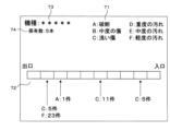
図12に示す画面の上部に、被検査内視鏡40の機種を示す機種欄73、当該機種の保有台数を示す保有数欄74および凡例欄71が表示されている。図12に示す画面の中央部から下に、履歴欄72が表示されている。
In the upper part of the screen shown in FIG. 12, a
履歴欄72には、長手方向に10等分したチャンネル45が模式的に表示されている。右側がチャンネル入口451側を示し、左側がチャンネル出口452側を示す。10等分したそれぞれの領域で、「破断」等の異常が過去に何件検出されたかが、それぞれ示されている。たとえば、チャンネル出口452側から2番目の領域では、「浅い傷」が5件、「軽度の汚れ」が23件検出されている。
In the
検査履歴DB52に記録されたデータに基づいて図12に示すレポートを作成する処理は、公知のデータ処理により行なえるため、説明を省略する。
Since the process of creating the report shown in FIG. 12 based on the data recorded in the
履歴欄72の表示は例示である。たとえば、位置と検出件数との関係は、棒グラフまたは折れ線グラフ等を用いて表示されてもよい。HISからそれぞれの内視鏡検査で被検査内視鏡40が使用された症例に関する情報を取得して、たとえば生検の有無等の手技ごとにレポートを作成してもよい。レポートは、内視鏡検査を実施した医師ごとに、または、洗浄作業を行なったコメディカルスタッフごとに作成されてもよい。
The display of the
本実施の形態によると、被検査内視鏡40に異常が発生しやすい場所、または、手技に関する情報をまとめたレポートを作成する検査システム10を提供できる。ユーザは、本実施の形態のレポートを用いて、被検査内視鏡40の破損防止策を検討できる。
According to the present embodiment, it is possible to provide the
レポートは、被検査内視鏡40のメーカーに提供されてもよい。メーカーは、破損しにくい被検査内視鏡40の開発にレポートを利用できる。
The report may be provided to the manufacturer of the
[実施の形態4]
本実施の形態は、内視鏡洗浄消毒装置に組み込まれた検査システム10に関する。実施の形態2と共通する部分については、説明を省略する。内視鏡洗浄消毒装置は、内視鏡の洗浄および消毒を自動的に行なう装置である。内視鏡洗浄消毒装置は公知であるため、詳細については説明を省略する。[Embodiment 4]
This embodiment relates to an
本実施の形態においては、検査用内視鏡30および進退装置39は、内視鏡洗浄消毒装置の洗浄槽に取り付けられている。検査用内視鏡30および進退装置39は、被検査内視鏡40と同時に洗浄および消毒されてもよい。そのようにすることにより、検査用内視鏡30による被検査内視鏡40の汚染を防止できる。
In the present embodiment, the
情報処理装置20は、内視鏡洗浄消毒装置の制御部を兼ねる。すなわち、本実施の形態の制御部21は内視鏡洗浄消毒装置を制御する洗浄装置制御部の機能を備える。
The
内視鏡検査の終了後、看護師または内視鏡技師等の担当者は、被検査内視鏡40のベッドサイド洗浄および用手洗浄を行なう。担当者は、被検査内視鏡40を内視鏡洗浄消毒装置にセットする。制御部21は、内視鏡洗浄消毒装置を制御して、被検査内視鏡40の洗浄および消毒を行なう。
After the endoscopy is completed, the person in charge such as a nurse or an endoscopist performs bedside cleaning and manual cleaning of the
洗浄および消毒の完了後、制御部21はチャンネル45に挿入部31を挿入して検査を行なう。洗浄消毒を再度行えば落ちる程度の軽度の汚れがある場合には、制御部21は内視鏡洗浄消毒装置を制御して、再度の洗浄および消毒を行なう。
After completion of cleaning and disinfection, the
洗浄槽に、セットした被検査内視鏡40のチャンネル出口452付近を撮影するカメラが設置されていてもよい。カメラで撮影した映像に基づいて、制御部21は挿入部31がチャンネル出口452に到達したことを検出できる。検査用内視鏡30に比べて高解像度の画像を撮影できるカメラを使用することにより、チャンネル45の状態に加えて、たとえば観察光学系、照明光学系および起上台等の洗浄状態を精度よく判定できる検査システム10を提供できる。
A camera for photographing the vicinity of the
図13は、実施の形態4のプログラムの処理の流れを説明するフローチャートである。制御部21は、被検査内視鏡40の機種等に関する情報を取得する(ステップS531)。制御部21は、被検査内視鏡40の機種に対応するモデル51を選択する(ステップS532)。
FIG. 13 is a flowchart for explaining the processing flow of the program according to the fourth embodiment. The
制御部21は、内視鏡洗浄消毒装置を動作させて、被検査内視鏡40の洗浄および消毒を行なう(ステップS533)。制御部21は、進退装置39を制御してチャンネル45への挿入部31の挿入を開始する(ステップS534)。
The
制御部21は、検査用内視鏡30から送信された検査画像を取得する(ステップS535)。制御部21は、ステップS535で取得した検査画像をステップS532で選択したモデル51に入力して、出力される判定結果を取得する(ステップS536)。
The
制御部21は、モデル51から取得された判定結果にチャンネル45の異常を示す情報が含まれているか否かを判定する(ステップS537)。異常を示す情報が含まれていると判定した場合(ステップS537でYES)、制御部21は、検査履歴DB52に新規レコードを作成して、異常があると判定された検査画像が撮影された際の位置と、判定結果と、検査画像とを記録する(ステップS538)。
The
異常を示す情報が含まれていないと判定した場合(ステップS537でNO)、またはステップS538の終了後、制御部21はチャンネル45の検査が終了したか否かを判定する(ステップS539)。検査が終了していないと判定した場合(ステップS539でNO)、制御部21はステップS535に戻る。
When it is determined that the information indicating abnormality is not included (NO in step S537), or after step S538 is completed, the
検査が終了したと判定した場合(ステップS539でYES)、制御部21は進退装置39を制御して挿入部31をチャンネル45から抜去する(ステップS540)。制御部21は、ステップS538で検査履歴DB52に記録した判定結果に基づいて再洗浄を行なうか否かを判定する。
If it is determined that the inspection has ended (YES in step S539), the
たとえば、「軽度の汚れ」等の再洗浄が必要である判定結果が含まれており、「破断」等の被検査内視鏡40をこれ以上使用できない判定結果が含まれていない場合、制御部21は再洗浄を行なうと判定する。既に再洗浄を所定の回数繰り返している場合は、制御部21は再洗浄を行なわないと判定する。
For example, if the determination result that rewashing is necessary such as "slightly soiled" is included and the determination result that the
再洗浄を行なうと判定した場合(ステップS541でYES)、制御部21はステップS533に戻る。再洗浄を行なわないと判定した場合(ステップS541でNO)、制御部21はリプロセス結果を内視鏡消毒洗浄装置の操作パネルを兼ねた表示部26に表示する(ステップS542)。その後、制御部21は処理を終了する。
If it is determined that re-cleaning is to be performed (YES in step S541),
図14は、実施の形態4の画面例を説明する説明図である。図14はステップS542で制御部21が表示する画面の一例である。画面の中央にリプロセスの結果を示す結果欄66が表示されている。画面の下部に、特記事項欄67が表示されている。
FIG. 14 is an explanatory diagram for explaining an example of a screen according to the fourth embodiment. FIG. 14 shows an example of a screen displayed by the
図14に示す例では、1回目のステップS541において制御部21は「軽度の汚れ」に伴う再洗浄が必要であると判定して(ステップS541でYES)、2回目の洗浄を行なった。2回目のステップS541においては「軽度の汚れ」が検出されなかったため、制御部21は図14に示す画面を表示して(ステップS542)処理を終了した。
In the example shown in FIG. 14, in the first step S541, the
担当者は、図14に示す画面を確認した後に被検査内視鏡40を内視鏡洗浄消毒装置から取り出す。仮に、「破断」等により被検査内視鏡40を使用できない旨が表示されている場合には、担当者は被検査内視鏡40を取り出して修理を手配する。
After confirming the screen shown in FIG. 14, the person in charge takes out the
本実施の形態によると、汚れの程度が少ない被検査内視鏡40に合わせて洗浄および消毒を行ない、必要に応じて自動的に洗浄を繰り返す内視鏡洗浄消毒装置を提供できる。消毒液等が被検査内視鏡40に与えるダメージを低減する内視鏡洗浄消毒装置および検査システム10を提供できる。
According to this embodiment, it is possible to provide an endoscope cleaning/disinfecting apparatus that cleans and disinfects an
再洗浄を行なうと判定した場合(ステップS541でYES)、制御部21は、用手洗浄のやりなおしが必要である旨を担当者に通知してもよい。たとえば制御部21は、「中度の汚れ」が残っている場合に、用手洗浄のやりなおしが必要である旨を通知し、「軽度の汚れ」のみが残っている場合に自動的に洗浄を繰り返す。
If it is determined that re-cleaning is to be performed (YES in step S541),
モデル51は、内視鏡洗浄消毒装置による再洗浄で除去できる程度の汚れであるか、用手洗浄が必要な程度の汚れであるかを出力するように学習されていてもよい。
The
[実施の形態5]
本実施の形態は、汎用のコンピュータ90とプログラム97とを組み合わせて動作させることにより、本実施の形態の検査システム10を実現する形態に関する。図15は、実施の形態5の検査システム10の構成を示す説明図である。実施の形態1と共通する部分については、説明を省略する。[Embodiment 5]
The present embodiment relates to a mode of realizing the
本実施の形態の検査システム10は、コンピュータ90を含む。コンピュータ90は、制御部21、主記憶装置22、補助記憶装置23、通信部24、表示部26、読取部28およびバスを備える。コンピュータ90は、汎用のパーソナルコンピュータ、タブレットまたはサーバコンピュータ等の情報機器である。
The
プログラム97は、可搬型記録媒体96に記録されている。制御部21は、読取部28を介してプログラム97を読み込み、補助記憶装置23に保存する。制御部21は、コンピュータ90内に実装されたフラッシュメモリ等の半導体メモリ98に記憶されたプログラム97を読出しても良い。制御部21は、通信部24および図示しないネットワークを介して接続される図示しない他のサーバコンピュータからプログラム97をダウンロードして補助記憶装置23に保存しても良い。
A
プログラム97は、コンピュータ90の制御プログラムとしてインストールされ、主記憶装置22にロードして実行される。これにより、コンピュータ90は上述した情報処理装置20として機能する。
The
[実施の形態6]
図16は、実施の形態6の情報処理装置20の機能ブロック図である。情報処理装置20は、被検査内視鏡40のチャンネル45に挿入された検査用内視鏡30により撮影された検査画像を取得する検査画像取得部81と、検査画像が入力された場合にチャンネル45の状態に関する判定予測を出力するモデル51に、検査画像取得部81が取得した検査画像を入力して、出力される判定予測を取得する判定取得部82と、検査画像と、判定予測とを関連づけて出力する出力部83とを備える。[Embodiment 6]
FIG. 16 is a functional block diagram of the
各実施例で記載されている技術的特徴(構成要件)はお互いに組合せ可能であり、組み合わせすることにより、新しい技術的特徴を形成することができる。
今回開示された実施の形態はすべての点で例示であって、制限的なものでは無いと考えられるべきである。本発明の範囲は、上記した意味では無く、請求の範囲によって示され、請求の範囲と均等の意味および範囲内でのすべての変更が含まれることが意図される。The technical features (constituent elements) described in each embodiment can be combined with each other, and new technical features can be formed by combining them.
It should be considered that the embodiments disclosed this time are illustrative in all respects and not restrictive. The scope of the present invention is not defined by the above-described meaning, but is indicated by the scope of claims, and is intended to include all modifications within the meaning and scope equivalent to the scope of claims.
10 検査システム
20 情報処理装置
21 制御部
22 主記憶装置
23 補助記憶装置
24 通信部
26 表示部
28 読取部
30 検査用内視鏡
31 挿入部
32 操作部
35 操作ボタン
36 表示部
37 把持部
39 進退装置
40 被検査内視鏡
41 挿入部
42 操作部
45 チャンネル
451 チャンネル入口
452 チャンネル出口
51 モデル
52 検査履歴DB
61 検査画像欄
62 異常部枠
63 過去情報欄
64 判定欄
65 通知内容欄
66 結果欄
67 特記事項欄
68 位置欄
71 凡例欄
72 履歴欄
73 機種欄
74 保有数欄
81 検査画像取得部
82 判定取得部
83 出力部
90 コンピュータ
96 可搬型記録媒体
97 プログラム
98 半導体メモリREFERENCE SIGNS
61
Claims (13)
検査画像が入力された場合にチャンネルの状態に関する判定予測を出力するモデルに、前記検査画像取得部が取得した検査画像を入力して、出力される判定予測を取得する判定取得部と、
前記検査画像が撮影された位置を取得する位置取得部と、
前記検査画像と、前記判定予測と、前記位置取得部が取得した位置とを関連づけて記録する検査履歴記録部と、
前記位置取得部が取得した位置に対応する過去の判定予測を前記検査履歴記録部が記録した記録から抽出する抽出部と、
前記検査画像と、前記判定予測と、前記位置取得部が取得した位置と、前記抽出部が抽出した過去の判定予測とを関連づけて出力する出力部と
を備える情報処理装置。 an inspection image acquisition unit that acquires an inspection image captured by an inspection endoscope inserted into a channel of an endoscope to be inspected;
a determination acquisition unit that inputs the inspection image acquired by the inspection image acquisition unit to a model that outputs a determination prediction regarding the state of a channel when the inspection image is input, and acquires an output determination prediction;
a position acquisition unit that acquires a position where the inspection image was captured;
an inspection history recording unit that associates and records the inspection image, the determination prediction, and the position acquired by the position acquisition unit;
an extraction unit that extracts a past determination prediction corresponding to the position acquired by the position acquisition unit from records recorded by the inspection history recording unit;
An information processing apparatus comprising: an output unit that associates and outputs the inspection image, the judgment prediction, the position acquired by the position acquisition unit, and the past judgment prediction extracted by the extraction unit .
請求項1に記載の情報処理装置。 The position is the length from the entrance of the channel
The information processing device according to claim 1 .
複数のモデルから、前記内視鏡情報に対応するモデルを選択するモデル選択部とを備える
請求項1または請求項2に記載の情報処理装置。 an endoscope information acquisition unit that acquires endoscope information about an endoscope to be inspected;
The information processing apparatus according to claim 1 or 2, further comprising a model selection unit that selects a model corresponding to the endoscope information from a plurality of models.
請求項3に記載の情報処理装置。 The model exists for each application of the endoscope to be inspected.
The information processing apparatus according to claim 3 .
請求項3または請求項4に記載の情報処理装置。 The model exists for each inner diameter of the channel
The information processing apparatus according to claim 3 or 4 .
請求項1から請求項5のいずれか一つに記載の情報処理装置。 The information processing apparatus according to any one of claims 1 to 5 , wherein the determination prediction includes a prediction regarding necessity of repair and a prediction regarding necessity of cleaning.
請求項1から請求項6のいずれか一つに記載の情報処理装置。 The information processing apparatus according to any one of claims 1 to 6, further comprising an advancing/retreating control section that controls an advancing/retreating device that advances/retracts an insertion portion of the examination endoscope inserted into the channel.
前記検査用内視鏡は、
被検査内視鏡のチャンネルに挿入されて、検査画像を撮影する撮影部と、
前記検査画像を出力する検査画像出力部とを有し、
前記情報処理装置は、
前記検査画像出力部から出力された検査画像を取得する検査画像取得部と、
検査画像が入力された場合にチャンネルの状態に関する判定予測を出力するモデルに、前記検査画像取得部が取得した検査画像を入力して、出力される判定予測を取得する判定取得部と、
前記検査画像が撮影された位置を取得する位置取得部と、
前記検査画像と、前記判定予測と、前記位置取得部が取得した位置とを関連づけて記録する検査履歴記録部と、
前記位置取得部が取得した位置に対応する過去の判定予測を前記検査履歴記録部が記録した記録から抽出する抽出部と、
前記検査画像と、前記判定予測と、前記位置取得部が取得した位置と、前記抽出部が抽出した過去の判定予測とを関連づけて出力する出力部と
を備える検査システム。 In an inspection system comprising an inspection endoscope and an information processing device, the inspection endoscope
an imaging unit that is inserted into a channel of an endoscope to be inspected and captures an inspection image;
an inspection image output unit that outputs the inspection image;
The information processing device is
an inspection image acquisition unit that acquires the inspection image output from the inspection image output unit;
a determination acquisition unit that inputs the inspection image acquired by the inspection image acquisition unit to a model that outputs a determination prediction regarding the state of a channel when the inspection image is input, and acquires an output determination prediction;
a position acquisition unit that acquires a position where the inspection image was captured;
an inspection history recording unit that associates and records the inspection image, the judgment prediction, and the position acquired by the position acquisition unit;
an extraction unit that extracts a past judgment prediction corresponding to the position acquired by the position acquisition unit from records recorded by the inspection history recording unit;
An inspection system comprising: an output unit that associates and outputs the inspection image, the judgment prediction, the position acquired by the position acquisition unit, and the past judgment prediction extracted by the extraction unit .
請求項8に記載の検査システム。 an advance/retreat device for advancing/retreating an insertion portion of the inspection endoscope inserted into the channel;
An inspection system according to claim 8 .
前記被検査内視鏡を洗浄する洗浄装置を制御する洗浄装置制御部を備え、
前記判定予測が、前記被検査内視鏡の再洗浄が必要であることを示す場合、前記洗浄装置に再洗浄を行なわせる
請求項8または請求項9に記載の検査システム。 The information processing device is
a cleaning device control unit that controls a cleaning device that cleans the endoscope to be inspected;
If the judgment prediction indicates that the endoscope to be inspected needs to be rewashed, causing the washing device to rewash.
The inspection system according to claim 8 or 9 .
請求項10に記載の検査システム。 The inspection endoscope is cleaned by the cleaning device together with the endoscope to be inspected.
11. The inspection system of claim 10 .
検査画像が入力された場合にチャンネルの状態に関する判定予測を出力するモデルに、取得した検査画像を入力して、出力される判定予測を取得し、
前記検査画像が撮影された位置を取得し、
前記検査画像と、前記判定予測と、前記検査画像が撮影された位置とを関連づけて記録し、
前記検査画像が撮影された位置に対応する過去の判定予測を過去の記録から抽出し、
前記検査画像と、前記判定予測と、前記検査画像が撮影された位置と、抽出した過去の判定予測とを関連づけて出力する
処理をコンピュータに実行させるプログラム。 Acquiring an inspection image captured by an inspection endoscope inserted into a channel of an endoscope to be inspected ,
inputting the acquired inspection image into a model that outputs a judgment prediction regarding the state of a channel when an inspection image is input, and acquiring an output judgment prediction;
Acquiring the position where the inspection image was taken,
recording the inspection image, the judgment prediction, and the position where the inspection image was taken in association with each other;
extracting a past judgment prediction corresponding to the position where the inspection image was taken from past records;
A program for causing a computer to execute a process of outputting the inspection image, the judgment prediction , the position where the inspection image was captured, and the extracted past judgment prediction in association with each other.
検査画像が入力された場合にチャンネルの状態に関する判定予測を出力するモデルに、取得した検査画像を入力して、出力される判定予測を取得し、
前記検査画像が撮影された位置を取得し、
前記検査画像と、前記判定予測と、前記検査画像が撮影された位置とを関連づけて記録し、
前記検査画像が撮影された位置に対応する過去の判定予測を過去の記録から抽出し、
前記検査画像と、前記判定予測と、前記検査画像が撮影された位置と、抽出した過去の判定予測とを関連づけて出力する
処理をコンピュータが実行する情報処理方法。 Acquiring an inspection image captured by an inspection endoscope inserted into a channel of an endoscope to be inspected,
inputting the acquired inspection image into a model that outputs a judgment prediction regarding the state of a channel when an inspection image is input, and acquiring an output judgment prediction;
Acquiring the position where the inspection image was taken,
recording the inspection image, the judgment prediction, and the position where the inspection image was taken in association with each other;
extracting a past judgment prediction corresponding to the position where the inspection image was taken from past records;
An information processing method in which a computer executes a process of outputting the inspection image, the determination prediction , the position where the inspection image was captured, and the extracted past determination prediction in association with each other.
Applications Claiming Priority (3)
| Application Number | Priority Date | Filing Date | Title |
|---|---|---|---|
| US202062988495P | 2020-03-12 | 2020-03-12 | |
| US62/988,495 | 2020-03-12 | ||
| PCT/JP2021/009986 WO2021182600A1 (en) | 2020-03-12 | 2021-03-12 | Information processing device, inspection system, program, and information processing method |
Publications (2)
| Publication Number | Publication Date |
|---|---|
| JPWO2021182600A1 JPWO2021182600A1 (en) | 2021-09-16 |
| JP7313542B2 true JP7313542B2 (en) | 2023-07-24 |
Family
ID=77671661
Family Applications (1)
| Application Number | Title | Priority Date | Filing Date |
|---|---|---|---|
| JP2022507296A Active JP7313542B2 (en) | 2020-03-12 | 2021-03-12 | Information processing device, inspection system, program and information processing method |
Country Status (5)
| Country | Link |
|---|---|
| US (1) | US12329353B2 (en) |
| EP (1) | EP4119933A4 (en) |
| JP (1) | JP7313542B2 (en) |
| CN (1) | CN115280138A (en) |
| WO (1) | WO2021182600A1 (en) |
Families Citing this family (4)
| Publication number | Priority date | Publication date | Assignee | Title |
|---|---|---|---|---|
| JP2023129970A (en) * | 2022-03-07 | 2023-09-20 | セイコーエプソン株式会社 | Defect discrimination device for printed images and its discrimination method |
| US20240029227A1 (en) * | 2022-07-19 | 2024-01-25 | Qualcomm Incorporated | Screen defect and contamination detection for mobile devices |
| JP2025536567A (en) * | 2022-10-25 | 2025-11-07 | クララス メディカル,リミティド ライアビリティ カンパニー | Medical Device Inspection System |
| FR3145470B1 (en) * | 2023-02-06 | 2025-01-31 | Axess Vision Tech | Method for determining whether the operating channel of a medical endoscope has been used |
Citations (5)
| Publication number | Priority date | Publication date | Assignee | Title |
|---|---|---|---|---|
| JP2012013675A (en) | 2010-05-31 | 2012-01-19 | Tohoku Electric Power Co Inc | Device and method for analyzing corrosion inside steel pipe |
| US20140150782A1 (en) | 2012-12-04 | 2014-06-05 | Endoclear Llc | Closed suction cleaning devices, systems and methods |
| US20180067051A1 (en) | 2013-02-26 | 2018-03-08 | Steris Inc. | Method and apparatus for optical detection of bio-contaminants within a lumen |
| US20180084162A1 (en) | 2016-09-21 | 2018-03-22 | SP Concepts, Inc. | Surgical instrument inspection system |
| WO2019219955A1 (en) | 2018-05-18 | 2019-11-21 | Ab Sandvik Materials Technology | Tube inspection system |
Family Cites Families (11)
| Publication number | Priority date | Publication date | Assignee | Title |
|---|---|---|---|---|
| JP2007147506A (en) | 2005-11-29 | 2007-06-14 | Fujifilm Corp | Piping inspection system and self-propelled piping inspection device used therefor |
| JP3920907B2 (en) * | 2006-04-03 | 2007-05-30 | オリンパス株式会社 | Wound inspection apparatus and endoscope apparatus provided with the wound inspection apparatus |
| EP2902066B1 (en) * | 2010-03-29 | 2021-03-10 | Endoclear LLC | Airway cleaning and visualization |
| EP2910173A4 (en) * | 2012-10-18 | 2016-06-01 | Olympus Corp | Image processing device, and image processing method |
| US20170323163A1 (en) * | 2016-05-06 | 2017-11-09 | City Of Long Beach | Sewer pipe inspection and diagnostic system and method |
| JP6796215B2 (en) | 2017-11-21 | 2020-12-02 | オリンパス株式会社 | Endoscope tip and endoscope |
| US11559597B2 (en) * | 2018-01-23 | 2023-01-24 | Clarus Medical, Llc | Medical device inspection system |
| EP3758641B1 (en) * | 2018-03-01 | 2026-01-14 | Auris Health, Inc. | Systems for mapping and navigation |
| WO2020096891A1 (en) | 2018-11-05 | 2020-05-14 | Medivators Inc. | Self-centering mechanism |
| US11715558B2 (en) * | 2019-06-25 | 2023-08-01 | Bh2 Innovations Inc. | Systems and methods for detecting defects in medical devices |
| CN110613417A (en) * | 2019-09-24 | 2019-12-27 | 浙江同花顺智能科技有限公司 | Method, equipment and storage medium for outputting upper digestion endoscope operation information |
-
2021
- 2021-03-12 CN CN202180019513.5A patent/CN115280138A/en active Pending
- 2021-03-12 WO PCT/JP2021/009986 patent/WO2021182600A1/en not_active Ceased
- 2021-03-12 US US17/910,524 patent/US12329353B2/en active Active
- 2021-03-12 JP JP2022507296A patent/JP7313542B2/en active Active
- 2021-03-12 EP EP21767767.3A patent/EP4119933A4/en active Pending
Patent Citations (5)
| Publication number | Priority date | Publication date | Assignee | Title |
|---|---|---|---|---|
| JP2012013675A (en) | 2010-05-31 | 2012-01-19 | Tohoku Electric Power Co Inc | Device and method for analyzing corrosion inside steel pipe |
| US20140150782A1 (en) | 2012-12-04 | 2014-06-05 | Endoclear Llc | Closed suction cleaning devices, systems and methods |
| US20180067051A1 (en) | 2013-02-26 | 2018-03-08 | Steris Inc. | Method and apparatus for optical detection of bio-contaminants within a lumen |
| US20180084162A1 (en) | 2016-09-21 | 2018-03-22 | SP Concepts, Inc. | Surgical instrument inspection system |
| WO2019219955A1 (en) | 2018-05-18 | 2019-11-21 | Ab Sandvik Materials Technology | Tube inspection system |
Non-Patent Citations (1)
| Title |
|---|
| Kavel Visrodia, MD and Bret T. Petersen, MD,"Borescope examination: Is there value in visual assessment of endoscope channels?",GASTROINTESTINAL ENDOSCOPY,2018年,Volume 88, No. 4,p. 620-623,<DOI: 10.1016/j.gie.2018.07.005> |
Also Published As
| Publication number | Publication date |
|---|---|
| US20230138418A1 (en) | 2023-05-04 |
| JPWO2021182600A1 (en) | 2021-09-16 |
| EP4119933A4 (en) | 2024-04-17 |
| US12329353B2 (en) | 2025-06-17 |
| CN115280138A (en) | 2022-11-01 |
| WO2021182600A1 (en) | 2021-09-16 |
| EP4119933A1 (en) | 2023-01-18 |
Similar Documents
| Publication | Publication Date | Title |
|---|---|---|
| JP7313542B2 (en) | Information processing device, inspection system, program and information processing method | |
| US12245904B2 (en) | Endoscope cleaning and inspection system and method | |
| KR102185886B1 (en) | Colonoscopy image analysis method and apparatus using artificial intelligence | |
| JP6603145B2 (en) | Endoscope cleaning management system | |
| JP5362768B2 (en) | Cleaning management device, program, and endoscope management system | |
| JP7017646B2 (en) | An image processing device for an endoscope, an operation method of the image processing device for an endoscope, and an image processing program for an endoscope. | |
| JP3647254B2 (en) | Endoscope cleaning and disinfection device | |
| JP2021037113A (en) | Processor for endoscope and generation method of learning model | |
| US20240148235A1 (en) | Information processing apparatus, information processing method, endoscope system, and report creation support device | |
| WO2020079777A1 (en) | Cleaning assistance system, processing device and cleaning assistance method | |
| CN115023171B (en) | Learning about medical image data generation devices, methods for generating medical image data, and recording media. | |
| US20240127531A1 (en) | Endoscopic examination support apparatus, endoscopic examination support method, and recording medium | |
| JP5872976B2 (en) | Medical image management device | |
| US20230115087A1 (en) | Provisioning system for endoscopes | |
| KR100921655B1 (en) | Image processing system of digestive organs with convenient entry of pathological findings on captured images | |
| JP7329392B2 (en) | Endoscope reprocess support device, endoscope reprocess support method and program | |
| CN118434345A (en) | Medical assistance system, medical assistance method and storage medium | |
| WO2024121886A1 (en) | Endoscopic examination assistance device, endoscopic examination assistance method, and recording medium | |
| CN115666361A (en) | Endoscope Processor Unit | |
| US12543925B2 (en) | Endoscopic examination support apparatus, endoscopic examination support method, and recording medium | |
| WO2018225326A1 (en) | Medical information processing system | |
| WO2023282143A1 (en) | Information processing device, information processing method, endoscopic system, and report creation assistance device | |
| WO2023135816A1 (en) | Medical assistance system and medical assistance method | |
| JP2024083943A (en) | ENDOSCOPE REPROCESSING SUPPORT SYSTEM, ENDOSCOPE REPROCESSING SUPPORT METHOD, AND ENDOSCOPE REPROCESSING SUPPORT PROGRAM | |
| WO2024121885A1 (en) | Information processing device, information processing method, and recording medium |
Legal Events
| Date | Code | Title | Description |
|---|---|---|---|
| A621 | Written request for application examination |
Free format text: JAPANESE INTERMEDIATE CODE: A621 Effective date: 20220620 |
|
| A131 | Notification of reasons for refusal |
Free format text: JAPANESE INTERMEDIATE CODE: A131 Effective date: 20230418 |
|
| A521 | Request for written amendment filed |
Free format text: JAPANESE INTERMEDIATE CODE: A523 Effective date: 20230606 |
|
| TRDD | Decision of grant or rejection written | ||
| A01 | Written decision to grant a patent or to grant a registration (utility model) |
Free format text: JAPANESE INTERMEDIATE CODE: A01 Effective date: 20230627 |
|
| A61 | First payment of annual fees (during grant procedure) |
Free format text: JAPANESE INTERMEDIATE CODE: A61 Effective date: 20230711 |
|
| R150 | Certificate of patent or registration of utility model |
Ref document number: 7313542 Country of ref document: JP Free format text: JAPANESE INTERMEDIATE CODE: R150 |