JP7279666B2 - Wiring material - Google Patents
Wiring material Download PDFInfo
- Publication number
- JP7279666B2 JP7279666B2 JP2020031929A JP2020031929A JP7279666B2 JP 7279666 B2 JP7279666 B2 JP 7279666B2 JP 2020031929 A JP2020031929 A JP 2020031929A JP 2020031929 A JP2020031929 A JP 2020031929A JP 7279666 B2 JP7279666 B2 JP 7279666B2
- Authority
- JP
- Japan
- Prior art keywords
- connector
- posture
- robot
- connectors
- linear transmission
- Prior art date
- Legal status (The legal status is an assumption and is not a legal conclusion. Google has not performed a legal analysis and makes no representation as to the accuracy of the status listed.)
- Active
Links
Images


Landscapes
- Insulated Conductors (AREA)
Description
この発明は、配線部材に関する。 The present invention relates to wiring members.
従来、ワイヤーハーネスの車両への組付作業、ワイヤーハーネスと補機との結合作業(コネクタ嵌合作業)は、人手によって行われていた。 Conventionally, the work of assembling the wire harness to the vehicle and the work of connecting the wire harness and the accessory (connector fitting work) have been performed manually.
近年、人口の低下や少子高齢化に伴い、労働人口の減少が懸念されている。自動車の製造作業の多くは、人により行われており、労働人口の確保が課題となる可能性がある。 In recent years, there is concern about a decrease in the working population due to the declining population and the declining birthrate and aging population. Much of the automobile manufacturing work is done by people, and securing a working population may be an issue.
これを解決すべく、車両製造工程の自動化が注目されている。また、製造コスト低減及び工程の効率化を狙い自動化を進める動きもある。 In order to solve this problem, automation of the vehicle manufacturing process is attracting attention. In addition, there is also a move to promote automation with the aim of reducing manufacturing costs and improving process efficiency.
コネクタの嵌合作業を自動化しようとすると、ロボットがワイヤーハーネス側のコネクタと補機側のコネクタの位置や向きを正しく認識し、嵌合作業を行う必要がある。しかしながら、従来のワイヤーハーネス構造(電線束)の場合、ワイヤーハーネスの動き自由度が非常に高く、またコネクタ自身も位置や向きを一定に保てる構造ではない。このため、ロボットが狙ったコネクタを認識し保持することが難しく、ロボットがコネクタ同士を嵌合させる作業を行うことは難しい。 When trying to automate the connector fitting work, it is necessary for the robot to correctly recognize the positions and orientations of the connector on the wire harness side and the connector on the accessory side, and perform the fitting work. However, in the case of the conventional wire harness structure (wire bundle), the wire harness has a very high degree of freedom of movement, and the connector itself is not structured to keep its position and orientation constant. For this reason, it is difficult for the robot to recognize and hold the intended connector, and it is difficult for the robot to perform the work of fitting the connectors together.
ここで、特許文献1は、複数のコネクタを所定順序で連結してコネクタ列を形成し、当該コネクタ列及びコネクタ間の組電線の弛み部分を、ガイドケースに収容する技術を開示している。特許文献1では、ロボットがガイドケースを保持して、コネクタを先頭から一個ずつ送出して相手側に組付けていくことが開示されている。 Here, Patent Literature 1 discloses a technique of connecting a plurality of connectors in a predetermined order to form a connector row, and accommodating the loosened portion of the assembled wire between the connector row and the connectors in a guide case. Patent Literature 1 discloses that a robot holds a guide case, feeds out connectors one by one from the top, and assembles them on the mating side.
また、特許文献2は、ワイヤーハーネスを巻付けるボビンに複数のコネクタホルダを設け、ワイヤーハーネスの複数のコネクタをコネクタホルダに一個ずつ保持する技術を開示している。特許文献2では、ボビンにワイヤーハーネスが巻付けられることによって構成された梱包体を、ロボットに取付けて、コネクタを一個ずつ相手側コネクタに組付けていくことが開示されている。 Further, Patent Literature 2 discloses a technique of providing a plurality of connector holders on a bobbin around which a wire harness is wound, and holding a plurality of connectors of the wire harness one by one in the connector holders. Japanese Patent Laid-Open No. 2002-200001 discloses that a package formed by winding a wire harness around a bobbin is attached to a robot, and connectors are assembled to mating connectors one by one.
しかしながら、特許文献1及び2に開示の技術では、ワイヤーハーネスの製造段階で、コネクタをガイドケース、又は、ボビンのコネクタホルダに保持させておく必要がある。このため、ワイヤーハーネスに対する制約が大である。例えば、ワイヤーハーネスが途中で分岐しているような場合には、適用困難な技術である。 However, with the techniques disclosed in Patent Documents 1 and 2, it is necessary to hold the connector in the guide case or the connector holder of the bobbin at the manufacturing stage of the wire harness. For this reason, there are great restrictions on the wire harness. For example, this technology is difficult to apply when the wire harness is branched on the way.
そこで、本発明は、コネクタを相手側コネクタに接続する作業を、ロボットで行うのに適した配線部材を提供することを目的とする。 SUMMARY OF THE INVENTION Accordingly, it is an object of the present invention to provide a wiring member suitable for a robot to connect a connector to a mating connector.
上記課題を解決するため、第1の態様に係る配線部材は、線状伝送部材と、前記線状伝送部材を2次元的に位置決めした状態で保持する保持部材と、前記線状伝送部材の端部に取付けられ、姿勢認識用マークが付されたコネクタとを備え、前記線状伝送部材は、芯線と芯線の周囲の被覆とを有する電線であり、前記コネクタは、前記電線の端部に取付けられた端子を収容可能なキャビティが形成されたコネクタとされている。 In order to solve the above problems, a wiring member according to a first aspect includes a linear transmission member, a holding member that holds the linear transmission member in a two-dimensionally positioned state, and an end of the linear transmission member. a connector attached to a part and having a posture recognition mark attached thereto, wherein the linear transmission member is an electric wire having a core wire and a covering around the core wire, and the connector is attached to an end of the electric wire. The connector is formed with a cavity capable of accommodating the terminals.
第2の態様は、第1の態様に係る配線部材であって、前記保持部材は、主面上に前記線状伝送部材が固定されたシート部材とされている。 A second aspect is the wiring member according to the first aspect, wherein the holding member is a sheet member having the linear transmission member fixed on its main surface.
第3の態様は、第1又は第2の態様に係る配線部材であって、前記姿勢認識用マークは、前記コネクタに対して先端寄りの位置に設けられているものである。 A third aspect is the wiring member according to the first or second aspect, wherein the posture recognition mark is provided at a position closer to the tip with respect to the connector.
第4の態様は、第1から第3のいずれか1つの態様に係る配線部材であって、前記保持部材は、前記線状伝送部材が延出する延出縁部を含み、前記線状伝送部材は、前記延出縁部から外方に延出する延出端部を含み、前記コネクタは前記延出端部に取付けられているものである。 A fourth aspect is the wiring member according to any one of the first to third aspects, wherein the holding member includes an extending edge from which the linear transmission member extends, and the linear transmission member The member includes an extension end extending outwardly from the extension edge, and the connector is attached to the extension end.
第5の態様は、第4の態様に係る配線部材であって、前記姿勢認識用マークは、少なくとも前記延出縁部に沿った軸周りの傾き姿勢を認識させるためのマークとされている。 A fifth aspect is the wiring member according to the fourth aspect, wherein the orientation recognition mark is a mark for recognizing an inclination orientation about an axis along at least the extension edge.
第6の態様は、第4又は第5の態様に係る配線部材であって、前記延出端部及び前記コネクタは、前記保持部材の前記延出縁部から外方に出た位置で片持ち状に支持されているものである。 A sixth aspect is the wiring member according to the fourth or fifth aspect, wherein the extending end portion and the connector are cantilevered at a position projecting outward from the extending edge portion of the holding member. It is supported in the form of
第7の態様は、第1から第6のいずれか1つの態様に係る配線部材であって、前記コネクタに、ロボット把持部の把持動作を受けて前記ロボット把持部に対する前記コネクタの姿勢を矯正する姿勢矯正ガイドが形成されているものである。 A seventh aspect is the wiring member according to any one of the first to sixth aspects, wherein the connector receives a gripping action of a robot gripping portion to correct the posture of the connector with respect to the robot gripping portion. A posture correction guide is formed.
第1の態様によると、保持部材によって線状伝送部材が2次元的に位置決めされた状態で保持されており、この線状伝送部材の端部にコネクタが取付けられている。このため、コネクタの位置は、保持部材によってある程度定められるため、ロボットは、当該コネクタを容易に把持することができる。また、コネクタには、姿勢認識用マークが付されているため、ロボットは、当該姿勢認識用マークに基づいてコネクタの姿勢を認識し、その認識結果に基づいて、コネクタの把持、相手側コネクタへの接続を行うことができる。従って、配線部材は、コネクタを相手側コネクタに接続する作業を、ロボットで行うのに適している。 According to the first aspect, the holding member holds the linear transmission member in a two-dimensionally positioned state, and the connector is attached to the end of the linear transmission member. Therefore, since the position of the connector is determined to some extent by the holding member, the robot can easily grip the connector. In addition, since the connector has a posture recognition mark attached, the robot recognizes the posture of the connector based on the posture recognition mark. connection can be made. Therefore, the wiring member is suitable for a robot to connect the connector to the mating connector.
第2の態様によると、シート部材によって線状伝送部材を2次元的に保持できる。 According to the second aspect, the linear transmission member can be two-dimensionally held by the sheet member.
第3の態様によると、姿勢認識用マークが、コネクタに対して先端寄りの位置に設けられているため、コネクタが相手側コネクタに接続されたかどうかを確認し易い。 According to the third aspect, since the posture recognition mark is provided at a position closer to the tip of the connector, it is easy to confirm whether the connector is connected to the mating connector.
第4の態様によると、線状伝送部材のうち保持部材の延出縁部から延出する延出端部に取付けられたコネクタは、保持部材に対して傾き易い。このような場合に、ロボットは、当該姿勢認識用マークに基づいてコネクタの姿勢を認識し、相手側コネクタへの接続に適した姿勢でコネクタを把持することができる。 According to the fourth aspect, the connector attached to the extension end of the linear transmission member extending from the extension edge of the holding member is likely to tilt with respect to the holding member. In such a case, the robot can recognize the orientation of the connector based on the orientation recognition mark, and can hold the connector in an orientation suitable for connection to the mating connector.
線状伝送部材のうち保持部材の延出縁部から延出する延出端部に取付けられたコネクタは、主として前記延出縁部に沿った軸周りに傾き易い。そこで、第5の態様のように、姿勢認識用マークとして、延出縁部に沿った軸周りの傾き姿勢を認識させるためのマークを付することで、ロボットは、コネクタの傾きを適切に認識できる。 A connector attached to an extension end portion of the linear transmission member that extends from the extension edge portion of the holding member tends to incline mainly around the axis along the extension edge portion. Therefore, as in the fifth aspect, by attaching a mark for recognizing the tilted posture about the axis along the extending edge as the posture recognition mark, the robot can appropriately recognize the tilt of the connector. can.
第6の態様によると、延出端部及びコネクタが、保持部材の延出縁部から外方に出た位置で片持ち状に支持されているため、保持部材に対するコネクタの位置及び姿勢は、ある程度一定範囲内に保たれる。このため、ロボットによるコネクタの認識、把持作業を行い易い。 According to the sixth aspect, since the extending end portion and the connector are supported in a cantilevered manner at a position projecting outward from the extending edge portion of the holding member, the position and posture of the connector with respect to the holding member are kept within a certain range. Therefore, it is easy for the robot to recognize and hold the connector.
第7の態様によると、ロボット把持部の把持動作を受けてロボット把持部に対する前記コネクタの姿勢を矯正することができるため、相手側コネクタへの接続に適した姿勢でコネクタを容易に把持することができる。 According to the seventh aspect, since the posture of the connector with respect to the robot gripping portion can be corrected in response to the gripping action of the robot gripping portion, the connector can be easily gripped in a posture suitable for connection to the mating connector. can be done.
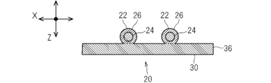
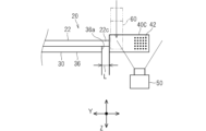
以下、実施形態に係る配線部材について説明する。図1は配線部材20を示す概略平面図であり、図2は図1のII-II線概略断面図であり、図3は配線部材20の1つの端末部を示す概略平面図であり、図4は同端末部の概略側面図であり、図5は図4においてコネクタが傾いている場合を示す概略側面図である。図4及び図5では撮像装置50及びロボット把持部60が図示されている。なお、各図に付したX方向、Y方向、Z方向の意義については後述する。
A wiring member according to an embodiment will be described below. 1 is a schematic plan view showing the
配線部材20は、線状伝送部材22と、保持部材30と、コネクタ40A、40B、40Cとを備える。
The
線状伝送部材22は、電気又は光を伝送する線状部材である。保持部材30は、線状伝送部材22を2次元的に位置決めした状態で保持する部材である。コネクタ40A、40B、40Cは、車両に搭載された部品に接続される部品である。コネクタ40A、40B、40Cが車両に搭載された部品の相手側のコネクタ48に接続されることで、線状伝送部材22と当該部品とが電気的に接続され、或は、光信号を送受可能に接続される。なお、相手側のコネクタ48は、車両に搭載された部品に設けられていることから、車両において一定位置に支持されていることが想定される。
The
本配線部材20が車両に搭載された状態で、複数のコネクタ40A、40B、40Cが車両に搭載された各部品に接続される。これにより、車両に搭載された部品の間で、電気信号の送受信、電力の送受、光信号の送受信がなされる。つまり、配線部材20は、車両に搭載された部品同士を接続する配線部品である。
With the
各部についてより具体的に説明する。 Each part will be described more specifically.
線状伝送部材22は、電気又は光等を伝送する線状の部材であればよい。例えば、線状伝送部材は、芯線と芯線の周囲の被覆とを有する一般電線であってもよいし、裸導線、シールド線、エナメル線、ニクロム線、光ファイバ等であってもよい。
The
電気を伝送する線状伝送部材としては、各種信号線、各種電力線であってもよい。電気を伝送する線状伝送部材は、信号又は電力を空間に対して送る又は空間から受けるアンテナ、コイル等として用いられてもよい。 Various signal lines and various power lines may be used as linear transmission members for transmitting electricity. Linear transmission members that transmit electricity may be used as antennas, coils, etc. that transmit signals or power to or receive signals from space.
ここでは線状伝送部材22が一般電線22(以下、単に電線22という)であるものとして説明する。電線22は、伝送線本体としての芯線24と、芯線24を覆う被覆26としての絶縁被覆26とを有する。電線22に関する各説明は、適用不可能な構成を除き、線状伝送部材22の各例示物に適用可能である。
Here, it is assumed that the
芯線24は、1本又は複数本の素線で構成される。素線は、銅、銅合金、アルミニウム、アルミニウム合金等の導体で形成される。芯線24が複数本の素線で構成される場合、複数本の素線は撚られていてもよい。絶縁被覆26は、PVC(ポリ塩化ビニル)、PE(ポリエチレン)などの樹脂材料が芯線24の周囲に押出成形されるなどして形成される。ここでは電線22は、横断面が円形のいわゆる丸電線である。
The
保持部材30は、電線22を2次元的に位置決めした状態で保持する部材である。保持部材30は、作業箇所等に載置された状態で、電線22を2次元的に位置決めした状態で保持できればよい。このため、保持部材30は、容易に曲り得る柔軟なシート状部材であってもよい。保持部材30は、湾曲しつつ電線22を2次元的に位置決めした状態で保持できる程度の剛性を有するシート状部材であってもよいし、平らな状態を保った状態で電線22を2次元的に位置決めした状態で保持できる程度の剛性を有するシート状部材であってもよい。保持部材30は、部分的に壁が立設される等、立体的な形状部分を有していてもよい。
The holding
ここでは、保持部材30は、曲げ可能なシート部材30であるものとして説明する。シート部材30に関する各説明は、適用不可能な構成を除き、保持部材に適用可能である。
Here, the holding
シート部材30を構成する材料は特に限定されるものではないが、シート部材30は、好ましくはPVC(ポリ塩化ビニル)、PET(ポリエチレンテレフタレート)、PP(ポリプロピレン)などの樹脂を含む材料によって形成される。シート部材30は、内部が一様に埋ったシート部材であってもよいし、不織シート等であってもよい。シート部材30は、金属などの材料を含むこともあり得る。シート部材30は、好ましくは、厚み方向において容易に曲る柔軟性を有する。シート部材30は、単層であってもよいし、複数層積層されていてもよい。複数層積層されている場合、例えば、樹脂層と樹脂層とが積層されていることが考えられる。また例えば、樹脂層と金属層とが積層されていることが考えられる。
Although the material forming the
シート部材30の一主面上に、電線22が固定されている。シート部材30の一主面上において、電線22は一定の経路に沿って固定されている。
A
シート部材30の一主面上に固定される電線22の数は、1本であってもよいし、複数本であってもよい。シート部材30上における電線22の経路は、直線であってもよいし、途中で曲る経路であってもよい。シート部材30の一主面上に複数の電線22が固定される場合、複数の電線22は途中で分岐していてもよいし、分岐していなくてもよい。
The number of
ここでは、シート部材30の一主面上に複数の電線22が固定されている。各電線22の経路は、車両において接続先となる部品の配置、各部品の間の他部品を避けるように設定される。ここでは、複数の電線22が途中で分岐するように保持部材30によって保持されている。図1に示す例では、複数の電線22の一方端部が1箇所にまとめられている。複数の電線22のうち一方端部寄りの部分は直線状かつ並列状態でシート部材30上に固定されている。複数の電線22の中間部は、複数に分岐されている。分岐した一方の電線22の群の他端部寄りの部分は、直線状かつ並列状態でシート部材30上に固定され、途中で側方に曲っている。分岐した他方の電線22の群の他端部寄りの部分は、並列状態を保ちつつ、外方に曲り、さらに、複数箇所(ここでは2箇所)で,曲って外方に延出している。
Here, a plurality of
シート部材30は、上記複数の電線22の経路に沿う形状に形成されている。ここでは、シート部材30は、複数の電線22の一方端寄りの部分を保持する第1帯状部分32と、分岐した一方の電線22の群の他端部寄りの部分を保持する第2帯状部分34と、分岐した他方の電線22の群の他端部寄りの部分を保持する第3帯状部分36とを含む。
The
第1帯状部分32は、複数の電線22を並列状態で保持可能な直線帯状に形成されている。第2帯状部分34は、第1帯状部分32に直線状に連なりかつ第1帯状部分32よりも細幅な直線帯状に形成されている。第3帯状部分36は、第1帯状部分32と第2帯状部分34との境界部分から外側方に延出し、途中で曲って第2帯状部分34に沿った方向に延在し、さらに途中で曲って第2帯状部分34の外側方に向けて延出する帯状に形成されている。
The first strip-shaped
シート部材30が複数の電線22の経路に沿った形状に形成されることで、シート部材30と他部品との干渉抑制、軽量化等が可能となる。シート部材30が複数の電線22の経路に沿った形状に形成されていることは必須ではなく、方形状等、他の形状に形成されていてもよい。
By forming the
シート部材30は、電線22が延出する延出縁部32a、34a、36aを含む。
The
ここでは、上記第1帯状部分32の外向き端部の縁が延出縁部32aである。複数の電線22の一方端部が当該延出縁部32aから外方に延出している。複数の電線22の一方端部のうち当該延出縁部32aから外方に延出する部分が延出端部22aである。
Here, the edge of the outward end portion of the first belt-
同様に、第2帯状部分34の外向き端部の縁が延出縁部34aである。分岐した一方の電線22の群の他方端部が当該延出縁部34aから外方に延出している。分岐した一方の電線22の群の他方端部のうち当該延出縁部34aから外方に延出する部分が延出端部22bである。
Similarly, the edge of the outward end of the
同様に、第3帯状部分36の外向き端部の縁が延出縁部36aである。分岐した他方の電線22の群の他方端部が当該延出縁部36aから外方に延出している。分岐した他方の電線22の群の他方端部のうち当該延出縁部36aから外方に延出する部分が延出端部22cである。
Similarly, the edge of the outward end of the third band-shaped
電線22とシート部材30とを固定する態様は、接触部位固定であってもよいし、非接触部位固定であってもよいし、両者が併用されていてもよい。ここで接触部位固定とは、電線22とシート部材30とが接触する部分がくっついて固定されているものである。また、非接触部位固定とは、接触部位固定でない固定態様である。例えば、縫糸、別のシート部材、粘着テープなどが、電線22をシート部材30に向けて押え込んだり、縫糸、別のシート部材、粘着テープなどが、電線22とシート部材30とを囲む状態等となって、電線22とシート部材30とを挟み込んだりして、電線22とシート部材30とが固定された状態に維持するものである。以下では、電線22とシート部材30とが、接触部位固定の状態にあるものとして説明する。接触部位固定に関する各説明は、適用不可能な構成でない限り、非接触部位固定にも適用可能である。
The mode of fixing the
係る接触部位固定の態様として、接触部位間接固定であってもよいし、接触部位直接固定であってもよいし、異なる領域で両者が併用されていてもよい。ここで接触部位間接固定とは、電線22とシート部材30とが、その間に設けられた接着剤、粘着剤、両面粘着テープなどの介在部材を介して間接的にくっついて固定されているものである。また接触部位直接固定とは、電線22とシート部材30とが別に設けられた接着剤等を介さずに直接くっついて固定されているものである。接触部位直接固定では、例えば電線22とシート部材30とのうち少なくとも一方に含まれる樹脂が溶かされることによってくっついて固定されることが考えられる。以下では、電線22とシート部材30とが、接触部位直接固定の状態にあるものとして説明する。接触部位直接固定に関する各説明は、適用不可能な構成でない限り、接触部位間接固定にも適用可能である。
Such contact site fixation may be indirect fixation at the contact site, direct fixation at the contact site, or both may be used in different regions. Here, the indirect fixation of the contact portion means that the
係る接触部位直接固定の状態が形成されるに当たり、樹脂は、例えば、熱によって溶かされることも考えられるし、溶剤によって溶かされることも考えられる。つまり、接触部位直接固定の状態としては、熱による接触部位直接固定の状態であってもよいし、溶剤による接触部位直接固定の状態であってもよい。好ましくは、熱による接触部位直接固定の状態であるとよい。 In forming such a state in which the contact portion is directly fixed, the resin may be melted, for example, by heat or melted by a solvent. That is, the state of direct fixation of the contact portion may be the state of direct fixation of the contact portion by heat or the state of direct fixation of the contact portion by solvent. Preferably, the contact portion is directly fixed by heat.
このとき接触部位直接固定の状態を形成する手段は特に限定されるものではなく、溶着、融着、溶接等の公知の手段を含む各種手段を用いることができる。例えば、溶着によって熱による接触部位直接固定の状態を形成する場合、超音波溶着、加熱加圧溶着、熱風溶着、高周波溶着など種々の溶着手段を採用することができる。またこれらの手段によって接触部位直接固定の状態が形成されると、電線22とシート部材30とは、その手段による接触部位直接固定の状態とされる。具体的には、例えば、超音波溶着によって接触部位直接固定の状態が形成されると、電線22とシート部材30とは、超音波溶着による接触部位直接固定の状態とされる。溶着によって熱による接触部位直接固定の状態を形成した部分(電線22とシート部材30との固定部分)を溶着部、このうち、超音波溶着による固定部分を超音波溶着部、加熱加圧溶着による固定部分を加熱加圧溶着部等と称してもよい。
At this time, the means for forming the state of direct fixation of the contact portion is not particularly limited, and various means including known means such as welding, fusing and welding can be used. For example, when the contact portion is directly fixed by heat by welding, various welding means such as ultrasonic welding, heat-pressure welding, hot-air welding, and high-frequency welding can be employed. Further, when the contact portion directly fixed state is formed by these means, the
接触部位直接固定の場合、電線22の被覆に含まれる樹脂のみが溶けていてもよいし、シート部材30に含まれる樹脂のみが溶けていてもよい。これらの場合において、溶けた方の樹脂が他方の外面にくっついた状態となり、比較的はっきりした界面が形成されることがある。また、接触部位直接固定の場合、電線22の被覆に含まれる樹脂とシート部材30に含まれる樹脂の両方が溶けていてもよい。この場合、両方の樹脂が混ざり合ってはっきりした界面が形成されないことがある。特に、電線22の被覆とシート部材30とが、同じ樹脂材料など相溶しやすい樹脂を含む場合などに、両方の樹脂が混ざり合ってはっきりした界面が形成されないことがある。
In the case of directly fixing the contact portion, only the resin contained in the coating of the
コネクタ40A、40B、40Cは、電線22の端部に取付けられている。つまり、延出端部22a、22b、22c及びコネクタ40A、40B、40Cは、シート部材30の延出縁部32a、34a、36aから外方に出た位置で片持ち状に支持されている。換言すれば、コネクタ40A、40B、40Cは、シート部材30の延出縁部32a、34a、36aから外方に出、完全に下方に向うようには垂下がらずに水平状態又は斜め姿勢で支持されている。
The
コネクタ40A、40B、40Cは、シート部材30に対してなるべく平行姿勢で片持ち状に支持されているとよい。しかしながら、シート部材30に対するコネクタ40A、40B、40Cの姿勢は、電線22の太さ、本数、コネクタ40A、40B、40Cの重量等によって左右される。例えば、シート部材30の延出縁部32a、34a、36aの手前部分に対して、コネクタ40A、40B、40Cは、±10度の範囲内で傾いていてもよいし、±5度の範囲内で傾いていてもよい(図5の角度θ参照)。コネクタ40A、40B、40Cの傾きをなるべく小さくするためには、延出縁部32a、34a、36aから延出する電線22の長さをなるべく短くするとよい。例えば、延出縁部32a、34a、36aとコネクタ40A、40B、40Cとの距離L(図4参照)を、10mmとしてもよいし、7mmとしてもよいし、5mmとしてもよいし、3mmとしてもよい。
The
コネクタ40A、40B、40Cは、電線22を他の部品に接続するための部品である。コネクタ40A、40B、40Cが電気コネクタであることを想定すると、コネクタ40A、40B、40Cは、電線22の端部に取付けられた端子を収容可能なキャビティが形成され、相手側コネクタ48に嵌合接続可能に構成されたものである。コネクタ40A、40B、40Cは、光コネクタであってもよい。
複数の電線22の一方側端部には、コネクタ40Aが接続されている。つまり、複数の電線22の延出端部22aにコネクタ40Aが取付けられている。
A
分岐した一方の電線22の群の他方側端部には、コネクタ40Bが接続されている。つまり、複数の電線22の延出端部22bにコネクタ40Bが取付られている。
A
分岐した他方の電線22の群の他方側端部には、コネクタ40Cが接続されている。つまり、複数の電線22の延出端部22cにコネクタ40Cが取付けられている。
A
電線22の端部がシート部材30から延出しており、その延出端部22a、22b、22cにコネクタ40A、40B、40Cが取付けられていることは必須ではない。電線22の端部がシート部材30から延出せず、コネクタ40A、40B、40Cがシート部材30の縁部に固定されていてもよい。
It is not essential that the ends of the
コネクタ40A、40B、40Cには、姿勢認識用マーク42が付されている。以下では、コネクタ40C及び当該コネクタ40Cに付された姿勢認識用マーク42を中心に説明する。なお、ここで、電線22の延出端部22cの延在方向をY方向、シート部材30に平行でかつY方向に直交する方向(又は延出縁部36aの延在方向)をX方向、X方向及びY方向に直交する方向(又はシート部材30の厚み方向)をZ方向ということとする。
Posture recognition marks 42 are attached to the
姿勢認識用マーク42は、撮像装置によって撮像した画像に基づいて、コンピュータが画像認識処理及び姿勢認識処理等を行うことによって、コネクタ40Cの姿勢を認識することができるマークである。
The
例えば、一定の規則で付された複数の点、直線等のマークは、画像認識処理及び姿勢認識処理を経てコネクタ40Cの姿勢を認識させるマークとして用いることができる。例えば、格子点状に付された複数の点を含むドットコード、QRコード(登録商標)、ARマーカー等は、そのマークが付された物体の姿勢を認識させるマークとして周知であり、これらを姿勢認識用マークとして用いてもよい。これらのドットコード、QRコード、ARマーカー等を撮像して、二値化処理等の画像認識処理を行い、その二値化画像等に基づいて、画像の大きさ、姿勢等の認識処理等の姿勢認識処理を行うことで、コネクタ40Cの姿勢を認識することができる。姿勢認識用マークとして、QRコード、ARマーカー等、他の情報を付加可能なマークを用いると、コンピュータによって、コネクタ40A、40B、40Cの姿勢に加えて、コネクタ40A、40B、40Cの種類を特定することも可能となる。
For example, marks such as a plurality of points or straight lines attached according to a certain rule can be used as marks for recognizing the orientation of the
姿勢認識用マーク42は、撮像装置によって撮像して画像処理可能であれば、如何なるマークであってもよい。姿勢認識用マーク42は、コネクタ40Cに対して、印刷されたものであってもよいし、姿勢認識用マーク42が印刷されたシールを貼付けたものであってもよいし、金型による凹凸形状として形成されたものであってもよい。印刷は、インクによる印刷であってもよいし、レーザ等によって表面を変質させて印刷したものであってもよい。姿勢認識用マーク42は、ホログラフィ技術によって、立体的に記録されたものであってもよい。
The
姿勢認識用マーク42は、延出縁部36aに沿った軸(X方向に沿った軸)周りにおけるコネクタ40Cの傾き姿勢を認識させるためのマークであってもよい。コネクタ40Cは、延出縁部36aに沿った軸(X方向に沿った軸)周りにおいて傾き易いため、姿勢認識用マーク42が少なくとも当該軸(X方向に沿った軸)周りにおけるコネクタ40Cの傾き姿勢を認識させるためのマークであれば、コネクタ40Cが傾き易い方向において、当該コネクタ40Cの姿勢をコンピュータによって認識させることが可能となる。
The
姿勢認識用マーク42は、コネクタ40Cに対して先端寄りの位置、即ち、コネクタ40Cの前後方向(接続方向)において中央寄りも先端寄りの位置に設けられていてもよい。これにより、例えば、コネクタ40Cが相手側のコネクタ48に内嵌めされる構成である場合、コネクタ40Cが相手側のコネクタ48に接続されると、姿勢認識用マーク42の全部又は一部が相手方のコネクタ48に隠れる(図6参照)。このため、コネクタ40Cに相手側のコネクタ48に接続した状態で、姿勢認識用マーク42の全部又は一部が相手方のコネクタ48に隠れているかを認識することで、コネクタ40Cが相手側のコネクタ48に完全に接続されているかどうかを判定することができる。
The
姿勢認識用マーク42に基づいて、コネクタ40A、40B、40Cの位置認識を行うようにしてもよい。
The positions of the
上記姿勢認識用マーク42を利用して、配線部材20を車両に組付ける作業例について説明する。垂直多関節ロボット等のロボットにて、自動で配線部材20を車両に組付けることを想定して説明する。
A work example of assembling the
この場合、まず、上記配線部材20を、車両の組付対象となる箇所近くに広げて載置する。載置箇所は、車両自体であってもよいし、その近くの作業台上であってもよい。また、他のロボットによって組付対象箇所近くに支持されていてもよい。配線部材20を展開した状態では、各電線22は、シート部材30によって所定の経路に沿った状態に保たれている。また、各延出縁部32a、34a、36aから延出する延出端部22a、22b、22cの端部にコネクタ40A、40B、40Cが取付けられているため、コネクタ40A、40B、40Cは、シート部材30に対しておおよそ一定位置に保持される。
In this case, first, the
そして、ロボット把持部にて上記コネクタ40A、40B、40Cを把持して、相手側のコネクタ48に接続していく。この場合、電線22の延出端部22a、22b、22cは、シート部材30の延出縁部32a、34a、36aから延出しているため、コネクタ40A、40B、40Cが傾いている可能性がある。
Then, the
ロボット把持部が、コネクタ40A、40B、40Cを、傾いた姿勢で把持してしまうと、コネクタ40A、40B、40Cを相手側コネクタ48に挿入しようとしても、うまく接続できない可能性がある。
If the robot gripper grips the
そこで、図4及び図5に示すように、撮像装置50にて姿勢認識用マーク42を撮像する。そして、コンピュータにて、撮像画像に基づいて画像処理、姿勢認識処理を実行し、コネクタ40Cの傾き姿勢を認識する。以下では、コネクタ40Cを中心に説明するが、他のコネクタ40A、40Bについても同様に処理及び作業可能である。
Therefore, as shown in FIGS. 4 and 5, the
そして、当該姿勢の認識結果に基づいて、ロボット把持部60に対してコネクタ40Cが所定の姿勢で把持されるように、ロボット把持部60の姿勢を変えて、ロボット把持部60がコネクタ40Cを把持する。例えば、図4に示すように、コネクタ40Cがシート部材30に対してほぼ水平姿勢である場合、ロボット把持部60は、シート部材30に対して直交する姿勢でコネクタ40Cを把持する。また、例えば、図5に示すように、コネクタ40Cがシート部材30に対して角度θ傾いている場合、ロボット把持部60は、シート部材30に対して直交する姿勢から角度θ傾けた状態でコネクタ40Cを把持する。これにより、ロボット把持部60は、コネクタ40Cの傾き姿勢に応じて、コネクタ40Cがロボット把持部60に対して所定の姿勢となるように把持できる。
Then, based on the posture recognition result, the posture of the
図5では、コネクタ40Cが、延出縁部36aに沿った軸(X方向に沿った軸)周りに傾いている場合を例として説明した。コネクタ40Cが、Y方向に沿った軸周りに傾いている場合、及び、Z方向に沿った軸周りに傾いている場合においても、同様にコネクタ40Cの傾きを認識し、当該傾きに応じてロボット把持部60を傾けた状態でコネクタ40Cを把持することで、ロボット把持部60は、上記と同様に、コネクタ40Cがロボット把持部60に対して所定の姿勢となるように当該コネクタ40Cを把持できる。
In FIG. 5, the case where the
なお、コネクタ40Cの重量等に起因して、コネクタ40Cは、延出縁部36aに沿った軸(X方向に沿った軸)周りにおいて傾き易い。特に、コネクタ40Cが複数極を有するコネクタであると、延出縁部36aから複数の延出端部22cが延出しており、複数の延出端部22cがコネクタ40Cに接続されている。このような場合には、コネクタ40Cは、複数本の延出端部22cによって支持されるため、コネクタ40Cは、Y方向に沿った軸周り及びZ方向に沿った軸周りにおいては、ある程度一定の姿勢で保持されるのに対し、延出縁部36aに沿った軸(X方向に沿った軸)周りにおいて傾き易いと考えられる。同様の考えから、コネクタ40Cは、シート部材30に対して、X方向及びY方向においてはある程度一定位置に保持される。これに対し、コネクタ40Cは、シート部材30に対して、Z方向(シート部材30の厚み方向)において相対的に位置変動し易いとも考えられる。
Due to the weight of the
そこで、姿勢認識用マーク42が少なくとも延出縁部36aに沿った軸(X方向に沿った軸)周りにおけるコネクタ40Cの傾き姿勢を認識させるものであると、多くの場合で、ロボット把持部60は、コネクタ40Cがロボット把持部60に対して所定の姿勢となるように当該コネクタ40Cを把持できる。
Therefore, in many cases, the
延出縁部36aに沿った軸(X方向に沿った軸)周りにおけるコネクタ40Cの傾き姿勢を認識させるためには、姿勢認識用マーク42はコネクタ40Cの側面に付されているとよい。もっとも、姿勢認識用マーク42はコネクタ40Cの上面等に付されていたとしても、その姿勢認識用マーク42の所定形状からの歪み等に基づいて、延出縁部36aに沿った軸(X方向に沿った軸)周りにおけるコネクタ40Cの傾き姿勢を認識することができる。また、コネクタ40Cに付された姿勢認識用マーク42は、コネクタ40CのZ方向における位置をコンピュータにて認識させるマークとしても役立つ。ロボット把持部60は、主としてZ方向に移動しつつコネクタ40Cを把持することで、コネクタ40Cをより確実に把持できる。この際、コネクタ40Cに付された姿勢認識用マーク42に基づいてコネクタ40CのZ方向における位置を認識することで、ロボット把持部60に対するコネクタ40Cの位置を一定に揃えたり、ロボット把持部60に対するコネクタ40Cの位置を認識したりし易い。
In order to recognize the tilted posture of the
上記のように、ロボット把持部60がコネクタ40Cを把持した後、図6に示すように、ロボット把持部60は、当該コネクタ40Cを相手側のコネクタ48に向けて移動させる。コネクタ40Cに接続された電線22及びこれを支持するシート部材30は、当該コネクタ40Cの移動に伴って移動する。そして、ロボット把持部60は、コネクタ40Cを相手側のコネクタ48に接続する。この際、ロボット把持部60に対してコネクタ40Cが所定の姿勢で把持されているため、コネクタ40Cと相手側のコネクタ48との位置合わせを行い易く、コネクタ40Cの接続作業を容易かつ確実に行える。
After the
コネクタ40Cを相手側のコネクタ48に接続すると、コネクタ40Cの先端寄りの位置に付された姿勢認識用マーク42の全部又は一部が相手側のコネクタ48によって隠れる。図6では、姿勢認識用マーク42が相手側のコネクタ48内に入り込んでその全体が隠れた状態が示されている。
When the
ロボット把持部60がコネクタ40Cを相手側のコネクタ48に接続した後、その接続箇所を撮像する。撮像画像において、姿勢認識用マーク42が認識されなければ、コネクタ40Cが相手側のコネクタ48に正常に接続されたと判定できる。なお、コネクタ40Cと相手側のコネクタ48との接続状態において、姿勢認識用マーク42の一部が隠れるように設定されている場合、撮像画像において、姿勢認識用マーク42の所定の残部のみが認識されると、コネクタ40Cが相手側のコネクタ48に正常に接続されたと判定できる。
After the
コネクタ40Cの先端寄りの位置に姿勢認識用マーク42を付することによるメリットは、ロボット把持部60によってコネクタ40Cを把持した状態で、当該ロボット把持部60がコネクタ40Cを所定の姿勢で把持できたかどうかを判別できる点にもある。すなわち、ロボット把持部60がコネクタ40Cを相手側コネクタ48に接続する際に、ロボット把持部60が相手側のコネクタ48に干渉しないようにするためには、ロボット把持部60は、コネクタ40Cの後端寄りの位置を把持するとよい。すると、ロボット把持部60がコネクタ40Cを把持した状態で、コネクタ40Cの先端寄りの部分を、ロボット把持部60によって隠れず、外側から認識可能な部分として露出させることができる。このため、コネクタ40Cの先端寄りの位置に姿勢認識用マーク42を付しておくと、ロボット把持部60がコネクタ40Cを把持した状態で、コネクタ40Cの姿勢認識用マーク42を撮像装置50によって撮像し、撮像結果に基づいてコネクタ40Cの姿勢を認識し、ロボット把持部60に対して所定の姿勢となっているかどうかを判定することができる。
The advantage of attaching the
他のコネクタ40A、40Bについても、上記と同様に、ロボット把持部60によって相手側のコネクタ48に接続するとよい。これにより、配線部材20が車両に自動で組付けられる。配線部材20の組付作業の一部は、人手等によってなされてもよい。
The
以上のように構成された配線部材20によると、保持部材であるシート部材30によって、線状伝送部材である電線22が2次元的に位置決めされた状態で保持されており、この電線22の端部にコネクタ40Cが取付けられている。このため、コネクタ40A、40B、40Cの位置は、シート部材30によってある程度定められることになり、ロボットは、ロボット把持部60によって当該コネクタ40A、40B、40Cを容易に把持することができる。また、コネクタ40A、40B、40Cには、姿勢認識用マーク42が付されているため、ロボットは、姿勢認識用マーク42に基づいてコネクタ40A、40B、40Cの姿勢を認識し、その認識結果に基づいて、コネクタ40A、40B、40Cの把持、相手側のコネクタ48への接続作業等を行うことができる。ロボット把持部60は、コネクタ40A、40B、40Cを所定の姿勢で把持できるため、当該把持及び接続作業を容易かつ確実に行うことができる。このため、本配線部材20は、コネクタ40A、40B、40Cを、相手側のコネクタ48に接続する作業を、ロボットで行うのに適している。
According to the
また、保持部材は、シート部材30であるため、電線22を容易に2次元的に保持できる。また、シート部材30が厚み方向に変形容易であれば、組付対象箇所の形状等に応じてシート部材30を厚み方向に変形させて、電線22を組付対象箇所に沿わせて配設し易い。
Further, since the holding member is the
特に、電線22のうちシート部材30の延出縁部32a、34a、36aから延出する延出端部22a、22b、22cに取付けられたコネクタ40A、40B、40Cは、シート部材30に対して傾き易い。このような場合に、ロボットは、姿勢認識用マーク42に基づいてコネクタ40A、40B、40Cの姿勢を認識し、相手側のコネクタ48への接続に適した姿勢でコネクタ40A、40B、40Cを把持することができる。
In particular, the
さらに、姿勢認識用マーク42が、少なくとも延出縁部32a、34a、36aに沿った軸周りの傾き姿勢を認識させるためのマークであれば、コネクタ40A、40B、40Cが傾き易い方向において、ロボットが、コネクタ40A、40B、40Cの傾きを適切に認識できる。
Furthermore, if the
延出縁部32a、34a、36aに沿った軸周りの傾き姿勢を認識させるためのマークとして、既に例示したマークの他、コネクタ40A、40B、40Cの側面に付された、コネクタ40A、40B、40Cの前後方向に沿った線であってもよいし、コネクタ40A、40B、40Cの上下方向に沿った線であってもよい。また、図7に示すように、姿勢認識用マーク42aは、前後方向に沿ったラインと上下方向に沿ったラインとが組合わされた十字マーク(図7参照)であってもよい。例えば、姿勢認識用マークは、コネクタ40A、40B、40Cの側面において前後方向に沿って離れた2つの位置に関する情報を含んでいてもよい。
As marks for recognizing tilted postures around the axes along the extension edges 32a, 34a, 36a, in addition to the marks already exemplified, the
また、姿勢認識用マーク42がコネクタ40A、40B、40Cに対して先端寄りの位置に設けられていると、コネクタ40A、40B、40Cが相手側のコネクタ48に接続された状態で、姿勢認識用マーク42の全部又は一部が隠れているかどうかを確認すること等により、コネクタ40A、40B、40Cが相手側のコネクタ48に正常に接続されたか否かを確認し易い。
Further, if the
また、延出端部22a、22b、22c及びコネクタ40A、40B、40Cが、シート部材30の延出縁部32a、34a、36aから外方に出た位置で片持ち状に支持されているため、シート部材30に対するコネクタ40A、40B、40Cがある程度一定範囲内に保たれる。このため、ロボットによるコネクタ40A、40B、40Cの認識、把持作業を行い易い。
Further, the extension ends 22a, 22b, 22c and the
{変形例}
図8及び図9に示す第1変形例のように、コネクタ40A、40B、40Cに対応するコネクタ140に、姿勢矯正ガイド144を設けてもよい。姿勢矯正ガイド144は、ロボット把持部160の把持動作を受けてロボット把持部160に対するコネクタ140の姿勢を矯正可能に構成されている。
{Modification}
As in the first modification shown in FIGS. 8 and 9, posture correction guides 144 may be provided on
ここでは、姿勢矯正ガイド144は、コネクタ140の上下方向に沿った溝であり、溝の幅方向中心に向けて順次深さ寸法が大きくなる形状、ここでは、三角溝状に形成されている。
Here, the
これに対して、ロボット把持部160の一対の把持部162の内面に、上記姿勢矯正ガイド144に嵌り込み可能な突部164、ここでは、断面三角形状の細長い突部164が形成されている。
On the other hand, on the inner surfaces of the pair of
そして、一対の把持部162を、コネクタ140の両側外方に配設した状態で、一対の把持部162を閉じると、一対の突部164が一対の姿勢矯正ガイド144に嵌り込む。この際、一対の突部164が姿勢矯正ガイド144の内面に接触し、一対の突部164の幅方向中央ラインが姿勢矯正ガイド144の幅方向中央ラインに向い、かつ、当該幅方向中央ラインに沿った状態となるように、ロボット把持部160に対するコネクタ140の位置及び姿勢が矯正される。
When the pair of
このため、ロボット把持部160に対してコネクタ140がより正確な位置及び姿勢となるように把持される。
Therefore, the
本第1変形例の姿勢矯正ガイド144は、ロボット把持部160に対してコネクタ140の姿勢を一定とするようにガイドする。より具体的には、姿勢矯正ガイド144は、一対の把持部162の延在方向に対してコネクタ140の前後方向が直交する姿勢となるようにガイドする。また、姿勢矯正ガイド144は、コネクタ140の前後方向において、ロボット把持部160に対してコネクタ140が一定位置に配設されるようにガイドする。
The
これにより、ロボット把持部160の把持動作を受けてロボット把持部160に対するコネクタ140の姿勢を矯正することができるため、相手側コネクタへの接続に適した姿勢でコネクタ140を容易に把持することができる。
As a result, the posture of the
上記したように、ロボット把持部160は、後のコネクタ接続作業を考慮するとコネクタ140の後端寄りの位置を把持するとよいため、この点からは、姿勢矯正ガイド144は、コネクタ140の後端寄りの位置に形成されているとよい。
As described above, the
図10に示す第2変形例では、コネクタ40A、40B、40Cに対応するコネクタ240に、別形状の姿勢矯正ガイド244を設けたものである。この姿勢矯正ガイド244は、上記姿勢矯正ガイド144のガイド機能に加えて、一対の把持部162の延在方向(コネクタ140の上下方向)においても、ロボット把持部に対してコネクタ240が一定位置に配設されるようにガイドする。
In the second modification shown in FIG. 10, a
ここでは、姿勢矯正ガイド244は、コネクタ240の側方のひし形の開口を底面として凹む四角錐状の凹形状に形成されている。このコネクタ240を把持するロボット把持部の一対の把持部には、上記姿勢矯正ガイド244の凹み形状に応じた四角錐状の突部を形成するとよい。そして、この一対の把持部によって上記コネクタ240を把持すると、当該四角錐状の突部が四角錐状に凹む姿勢矯正ガイド244の側面に当接する。そして、一対の把持部の突部が四角錐状に凹む姿勢矯正ガイド244に嵌り込むことにより、コネクタ240が一対の把持部に対して一定の姿勢となるようにガイドされる。また、コネクタ240が一対の把持部に対して前後及び上下方向において一定位置に配設されるようにガイドされる。このため、ロボット把持部に対してコネクタ240がより正確に一定位置に配設されかつ一定姿勢となるようにガイドする。
Here, the
姿勢矯正ガイド244は、その他、三角溝形状が十字にクロスした形状、円錐形状等であってもよい。
The
上記第1変形例及び第2変形例は、ロボット把持部に対してコネクタを一定姿勢にガイドする構造として、姿勢認識用マークを付さないコネクタにも適用可能である。 The first modification and the second modification can be applied to a connector that does not have a posture recognition mark as a structure for guiding the connector to a fixed posture with respect to the robot gripping portion.
また、上記実施形態において、相手側のコネクタ48に、姿勢認識用マークを設けてもよい。これにより、ロボットがコネクタ40A、40B、40Cを、相手側のコネクタ48に接続する際に、当該相手側のコネクタ48の姿勢等を認識し、その認識結果に基づいてコネクタ40A、40B、40Cの姿勢を補正して接続作業を行うことができ、より正確な接続作業が可能となる。
Further, in the above embodiment, the
なお、上記実施形態及び各変形例で説明した各構成は、相互に矛盾しない限り適宜組合わせることができる。
また、本開示は、下記の各態様を開示する。
第1の態様に係る配線部材は、線状伝送部材と、前記線状伝送部材を2次元的に位置決めした状態で保持する保持部材と、前記線状伝送部材の端部に取付けられ、姿勢認識用マークが付されたコネクタとを備える。
第2の態様は、第1の態様に係る配線部材であって、前記保持部材は、主面上に前記線状伝送部材が固定されたシート部材とされている。
第3の態様は、第1又は第2の態様に係る配線部材であって、前記姿勢認識用マークは、前記コネクタに対して先端寄りの位置に設けられているものである。
第4の態様は、第1から第3のいずれか1つの態様に係る配線部材であって、前記保持部材は、前記線状伝送部材が延出する延出縁部を含み、前記線状伝送部材は、前記延出縁部から外方に延出する延出端部を含み、前記コネクタは前記延出端部に取付けられているものである。
第5の態様は、第4の態様に係る配線部材であって、前記姿勢認識用マークは、少なくとも前記延出縁部に沿った軸周りの傾き姿勢を認識させるためのマークとされている。
第6の態様は、第4又は第5の態様に係る配線部材であって、前記延出端部及び前記コネクタは、前記保持部材の前記延出縁部から外方に出た位置で片持ち状に支持されているものである。
第7の態様は、第1から第6のいずれか1つの態様に係る配線部材であって、前記コネクタに、ロボット把持部の把持動作を受けて前記ロボット把持部に対する前記コネクタの姿勢を矯正する姿勢矯正ガイドが形成されているものである。
第1の態様によると、保持部材によって線状伝送部材が2次元的に位置決めされた状態で保持されており、この線状伝送部材の端部にコネクタが取付けられている。このため、コネクタの位置は、保持部材によってある程度定められるため、ロボットは、当該コネクタを容易に把持することができる。また、コネクタには、姿勢認識用マークが付されているため、ロボットは、当該姿勢認識用マークに基づいてコネクタの姿勢を認識し、その認識結果に基づいて、コネクタの把持、相手側コネクタへの接続を行うことができる。従って、配線部材は、コネクタを相手側コネクタに接続する作業を、ロボットで行うのに適している。
第2の態様によると、シート部材によって線状伝送部材を2次元的に保持できる。
第3の態様によると、姿勢認識用マークが、コネクタに対して先端寄りの位置に設けられているため、コネクタが相手側コネクタに接続されたかどうかを確認し易い。
第4の態様によると、線状伝送部材のうち保持部材の延出縁部から延出する延出端部に取付けられたコネクタは、保持部材に対して傾き易い。このような場合に、ロボットは、当該姿勢認識用マークに基づいてコネクタの姿勢を認識し、相手側コネクタへの接続に適した姿勢でコネクタを把持することができる。
線状伝送部材のうち保持部材の延出縁部から延出する延出端部に取付けられたコネクタは、主として前記延出縁部に沿った軸周りに傾き易い。そこで、第5の態様のように、姿勢認識用マークとして、延出縁部に沿った軸周りの傾き姿勢を認識させるためのマークを付することで、ロボットは、コネクタの傾きを適切に認識できる。
第6の態様によると、延出端部及びコネクタが、保持部材の延出縁部から外方に出た位置で片持ち状に支持されているため、保持部材に対するコネクタの位置及び姿勢は、ある程度一定範囲内に保たれる。このため、ロボットによるコネクタの認識、把持作業を行い易い。
第7の態様によると、ロボット把持部の把持動作を受けてロボット把持部に対する前記コネクタの姿勢を矯正することができるため、相手側コネクタへの接続に適した姿勢でコネクタを容易に把持することができる。
It should be noted that the configurations described in the above embodiment and modifications can be appropriately combined as long as they do not contradict each other.
In addition, the present disclosure discloses each of the following aspects.
A wiring member according to a first aspect includes a linear transmission member, a holding member that holds the linear transmission member in a two-dimensionally positioned state, and an end portion of the linear transmission member that is attached to the wiring member to recognize the posture. and a connector marked for use.
A second aspect is the wiring member according to the first aspect, wherein the holding member is a sheet member having the linear transmission member fixed on its main surface.
A third aspect is the wiring member according to the first or second aspect, wherein the posture recognition mark is provided at a position closer to the tip with respect to the connector.
A fourth aspect is the wiring member according to any one of the first to third aspects, wherein the holding member includes an extending edge from which the linear transmission member extends, and the linear transmission member The member includes an extension end extending outwardly from the extension edge, and the connector is attached to the extension end.
A fifth aspect is the wiring member according to the fourth aspect, wherein the orientation recognition mark is a mark for recognizing an inclination orientation about an axis along at least the extension edge.
A sixth aspect is the wiring member according to the fourth or fifth aspect, wherein the extending end portion and the connector are cantilevered at a position projecting outward from the extending edge portion of the holding member. It is supported in the form of
A seventh aspect is the wiring member according to any one of the first to sixth aspects, wherein the connector receives a gripping action of a robot gripping portion to correct the posture of the connector with respect to the robot gripping portion. A posture correction guide is formed.
According to the first aspect, the holding member holds the linear transmission member in a two-dimensionally positioned state, and the connector is attached to the end of the linear transmission member. Therefore, since the position of the connector is determined to some extent by the holding member, the robot can easily grip the connector. In addition, since the connector has a posture recognition mark attached, the robot recognizes the posture of the connector based on the posture recognition mark. connection can be made. Therefore, the wiring member is suitable for a robot to connect the connector to the mating connector.
According to the second aspect, the linear transmission member can be two-dimensionally held by the sheet member.
According to the third aspect, since the posture recognition mark is provided at a position closer to the tip of the connector, it is easy to confirm whether the connector is connected to the mating connector.
According to the fourth aspect, the connector attached to the extension end of the linear transmission member extending from the extension edge of the holding member is likely to tilt with respect to the holding member. In such a case, the robot can recognize the orientation of the connector based on the orientation recognition mark, and can hold the connector in an orientation suitable for connection to the mating connector.
A connector attached to an extension end portion of the linear transmission member that extends from the extension edge portion of the holding member tends to incline mainly around the axis along the extension edge portion. Therefore, as in the fifth aspect, by attaching a mark for recognizing the tilted posture about the axis along the extending edge as the posture recognition mark, the robot can appropriately recognize the tilt of the connector. can.
According to the sixth aspect, since the extending end portion and the connector are supported in a cantilevered manner at a position projecting outward from the extending edge portion of the holding member, the position and posture of the connector with respect to the holding member are kept within a certain range. Therefore, it is easy for the robot to recognize and hold the connector.
According to the seventh aspect, since the posture of the connector with respect to the robot gripping portion can be corrected in response to the gripping action of the robot gripping portion, the connector can be easily gripped in a posture suitable for connection to the mating connector. can be done.
以上のようにこの発明は詳細に説明されたが、上記した説明は、すべての局面において、例示であって、この発明がそれに限定されるものではない。例示されていない無数の変形例が、この発明の範囲から外れることなく想定され得るものと解される。 Although the present invention has been described in detail as above, the above description is illustrative in all aspects, and the present invention is not limited thereto. It is understood that numerous variations not illustrated can be envisioned without departing from the scope of the invention.
20 配線部材
22 線状伝送部材(電線)
22a、22b、22c 延出端部
30 保持部材(シート部材)
32a、34a、36a 延出縁部
40A、40B、40C、140、240 コネクタ
42、42a 姿勢認識用マーク
144、244 姿勢矯正ガイド
160 ロボット把持部
162 把持部
164 突部
244 姿勢矯正ガイド
20
22a, 22b,
32a, 34a,
Claims (5)
前記線状伝送部材を2次元的に位置決めした状態で保持する保持部材と、
前記線状伝送部材の端部に取付けられ、姿勢認識用マークが付されたコネクタと、
を備え、
前記線状伝送部材は、芯線と芯線の周囲の被覆とを有する電線であり、
前記コネクタは、前記電線の端部に取付けられた端子を収容可能なキャビティが形成されたコネクタであり、
前記姿勢認識用マークは、前記コネクタに対して先端寄りの位置に設けられている、配線部材。 a linear transmission member;
a holding member that holds the linear transmission member in a two-dimensionally positioned state;
a connector attached to an end of the linear transmission member and having a posture recognition mark;
with
The linear transmission member is an electric wire having a core wire and a coating around the core wire,
The connector is a connector formed with a cavity capable of accommodating a terminal attached to an end of the electric wire,
The wiring member, wherein the posture recognition mark is provided at a position closer to the tip of the connector.
前記保持部材は、前記線状伝送部材が延出する延出縁部を含み、
前記線状伝送部材は、前記延出縁部から外方に延出する延出端部を含み、
前記コネクタは前記延出端部に取付けられている、配線部材。 The wiring member according to claim 1 ,
the holding member includes an extending edge from which the linear transmission member extends,
the linear transmission member includes an extension end portion extending outward from the extension edge portion;
The wiring member, wherein the connector is attached to the extension end.
前記姿勢認識用マークは、少なくとも前記延出縁部に沿った軸周りの傾き姿勢を認識させるためのマークである、配線部材。 The wiring member according to claim 2 ,
The wiring member, wherein the orientation recognition mark is a mark for recognizing an inclination orientation about an axis along at least the extension edge.
前記延出端部及び前記コネクタは、前記保持部材の前記延出縁部から外方に出た位置で片持ち状に支持されている、配線部材。 The wiring member according to claim 2 or 3 ,
The wiring member, wherein the extending end portion and the connector are supported in a cantilever manner at a position projecting outward from the extending edge portion of the holding member.
前記コネクタに、ロボット把持部の把持動作を受けて前記ロボット把持部に対する前記コネクタの姿勢を矯正する姿勢矯正ガイドが形成されている、配線部材。 The wiring member according to any one of claims 1 to 4 ,
A wiring member, wherein the connector is formed with a posture correcting guide that receives a gripping action of a robot gripping portion and corrects a posture of the connector with respect to the robot gripping portion.
Priority Applications (1)
| Application Number | Priority Date | Filing Date | Title |
|---|---|---|---|
| JP2020031929A JP7279666B2 (en) | 2020-02-27 | 2020-02-27 | Wiring material |
Applications Claiming Priority (1)
| Application Number | Priority Date | Filing Date | Title |
|---|---|---|---|
| JP2020031929A JP7279666B2 (en) | 2020-02-27 | 2020-02-27 | Wiring material |
Related Parent Applications (1)
| Application Number | Title | Priority Date | Filing Date |
|---|---|---|---|
| JP2018175385A Division JP6673419B2 (en) | 2018-09-19 | 2018-09-19 | Wiring member |
Publications (3)
| Publication Number | Publication Date |
|---|---|
| JP2020095969A JP2020095969A (en) | 2020-06-18 |
| JP2020095969A5 JP2020095969A5 (en) | 2020-08-20 |
| JP7279666B2 true JP7279666B2 (en) | 2023-05-23 |
Family
ID=71086439
Family Applications (1)
| Application Number | Title | Priority Date | Filing Date |
|---|---|---|---|
| JP2020031929A Active JP7279666B2 (en) | 2020-02-27 | 2020-02-27 | Wiring material |
Country Status (1)
| Country | Link |
|---|---|
| JP (1) | JP7279666B2 (en) |
Families Citing this family (1)
| Publication number | Priority date | Publication date | Assignee | Title |
|---|---|---|---|---|
| JP7662938B2 (en) | 2021-04-06 | 2025-04-16 | 株式会社デンソーウェーブ | Machine learning device, machine learning method, and robot control device |
Citations (5)
| Publication number | Priority date | Publication date | Assignee | Title |
|---|---|---|---|---|
| JP2006244748A (en) | 2005-03-01 | 2006-09-14 | Furukawa Electric Co Ltd:The | Cassette type wire harness and assembling method thereof |
| JP2017027693A (en) | 2015-07-17 | 2017-02-02 | 日立金属株式会社 | Wire harness manufacturing method |
| JP2017524600A (en) | 2014-07-02 | 2017-08-31 | ダイバージェント テクノロジーズ,インコーポレイテッド | System and method for manufacturing joint members |
| JP2018014218A (en) | 2016-07-20 | 2018-01-25 | 矢崎総業株式会社 | System for producing wire harness |
| JP2018073495A (en) | 2016-10-25 | 2018-05-10 | 住友電装株式会社 | Manufacturing support device for wire harness |
Family Cites Families (2)
| Publication number | Priority date | Publication date | Assignee | Title |
|---|---|---|---|---|
| JPH0628922A (en) * | 1992-07-08 | 1994-02-04 | Sumitomo Wiring Syst Ltd | Flat harness and manufacture thereof |
| JP3565951B2 (en) * | 1995-07-20 | 2004-09-15 | 矢崎総業株式会社 | Wire harness and method of manufacturing the same |
-
2020
- 2020-02-27 JP JP2020031929A patent/JP7279666B2/en active Active
Patent Citations (5)
| Publication number | Priority date | Publication date | Assignee | Title |
|---|---|---|---|---|
| JP2006244748A (en) | 2005-03-01 | 2006-09-14 | Furukawa Electric Co Ltd:The | Cassette type wire harness and assembling method thereof |
| JP2017524600A (en) | 2014-07-02 | 2017-08-31 | ダイバージェント テクノロジーズ,インコーポレイテッド | System and method for manufacturing joint members |
| JP2017027693A (en) | 2015-07-17 | 2017-02-02 | 日立金属株式会社 | Wire harness manufacturing method |
| JP2018014218A (en) | 2016-07-20 | 2018-01-25 | 矢崎総業株式会社 | System for producing wire harness |
| JP2018073495A (en) | 2016-10-25 | 2018-05-10 | 住友電装株式会社 | Manufacturing support device for wire harness |
Also Published As
| Publication number | Publication date |
|---|---|
| JP2020095969A (en) | 2020-06-18 |
Similar Documents
| Publication | Publication Date | Title |
|---|---|---|
| TWI591917B (en) | Wire processing device and method of manufacturing wiring module | |
| US12300406B2 (en) | Wiring member | |
| CN111869026B (en) | Wiring body with assembling auxiliary member, assembling auxiliary member of wiring body, and manufacturing method of wiring body assembly | |
| JP7279666B2 (en) | Wiring material | |
| US20220029400A1 (en) | Wiring member and wiring member in packaged form | |
| JP6673419B2 (en) | Wiring member | |
| CN113632181B (en) | Wiring parts | |
| US12159733B2 (en) | Wiring member | |
| US11501894B2 (en) | Wiring member | |
| JP6687180B1 (en) | Wiring member | |
| CN114667577B (en) | Wiring components | |
| JPH10203271A (en) | Manufacture of wire harnesses for automobiles | |
| JP7276557B2 (en) | Wire harness information management system | |
| KR102853042B1 (en) | Collaborative multi robot based automatic process system for assembling and inspecting wiring harness | |
| JP7306306B2 (en) | Wiring material | |
| WO2020241302A1 (en) | Wiring member | |
| JP2020167142A (en) | Wiring member and assembling method of wiring member | |
| JP2012120339A (en) | Wire harness | |
| JP2012120361A (en) | Wire harness | |
| JP2009301975A (en) | Wiring material |
Legal Events
| Date | Code | Title | Description |
|---|---|---|---|
| A521 | Request for written amendment filed |
Free format text: JAPANESE INTERMEDIATE CODE: A523 Effective date: 20200713 |
|
| A621 | Written request for application examination |
Free format text: JAPANESE INTERMEDIATE CODE: A621 Effective date: 20210830 |
|
| A977 | Report on retrieval |
Free format text: JAPANESE INTERMEDIATE CODE: A971007 Effective date: 20220421 |
|
| A131 | Notification of reasons for refusal |
Free format text: JAPANESE INTERMEDIATE CODE: A131 Effective date: 20220510 |
|
| A521 | Request for written amendment filed |
Free format text: JAPANESE INTERMEDIATE CODE: A523 Effective date: 20220629 |
|
| A131 | Notification of reasons for refusal |
Free format text: JAPANESE INTERMEDIATE CODE: A131 Effective date: 20221018 |
|
| A601 | Written request for extension of time |
Free format text: JAPANESE INTERMEDIATE CODE: A601 Effective date: 20221215 |
|
| A521 | Request for written amendment filed |
Free format text: JAPANESE INTERMEDIATE CODE: A523 Effective date: 20230215 |
|
| TRDD | Decision of grant or rejection written | ||
| A01 | Written decision to grant a patent or to grant a registration (utility model) |
Free format text: JAPANESE INTERMEDIATE CODE: A01 Effective date: 20230411 |
|
| A61 | First payment of annual fees (during grant procedure) |
Free format text: JAPANESE INTERMEDIATE CODE: A61 Effective date: 20230424 |
|
| R150 | Certificate of patent or registration of utility model |
Ref document number: 7279666 Country of ref document: JP Free format text: JAPANESE INTERMEDIATE CODE: R150 |
|
| R250 | Receipt of annual fees |
Free format text: JAPANESE INTERMEDIATE CODE: R250 |