JP2018014218A - System for producing wire harness - Google Patents
System for producing wire harness Download PDFInfo
- Publication number
- JP2018014218A JP2018014218A JP2016142658A JP2016142658A JP2018014218A JP 2018014218 A JP2018014218 A JP 2018014218A JP 2016142658 A JP2016142658 A JP 2016142658A JP 2016142658 A JP2016142658 A JP 2016142658A JP 2018014218 A JP2018014218 A JP 2018014218A
- Authority
- JP
- Japan
- Prior art keywords
- work
- display
- manufacturing system
- wire harness
- worker
- Prior art date
- Legal status (The legal status is an assumption and is not a legal conclusion. Google has not performed a legal analysis and makes no representation as to the accuracy of the status listed.)
- Abandoned
Links
- 238000004519 manufacturing process Methods 0.000 claims abstract description 108
- 238000004804 winding Methods 0.000 claims description 24
- 238000010586 diagram Methods 0.000 abstract description 14
- 238000012937 correction Methods 0.000 description 23
- 239000003550 marker Substances 0.000 description 23
- 238000000034 method Methods 0.000 description 18
- 238000012986 modification Methods 0.000 description 13
- 230000004048 modification Effects 0.000 description 13
- 230000008569 process Effects 0.000 description 9
- 238000013461 design Methods 0.000 description 5
- 230000008859 change Effects 0.000 description 3
- 230000006872 improvement Effects 0.000 description 3
- 238000012545 processing Methods 0.000 description 3
- 239000011248 coating agent Substances 0.000 description 2
- 238000000576 coating method Methods 0.000 description 2
- 238000004891 communication Methods 0.000 description 2
- 230000000694 effects Effects 0.000 description 2
- 239000011347 resin Substances 0.000 description 2
- 229920005989 resin Polymers 0.000 description 2
- 230000004308 accommodation Effects 0.000 description 1
- 230000003190 augmentative effect Effects 0.000 description 1
- 230000008901 benefit Effects 0.000 description 1
- 230000004397 blinking Effects 0.000 description 1
- 238000009795 derivation Methods 0.000 description 1
- 238000005516 engineering process Methods 0.000 description 1
- 230000006698 induction Effects 0.000 description 1
- 239000000463 material Substances 0.000 description 1
- 125000000391 vinyl group Chemical group [H]C([*])=C([H])[H] 0.000 description 1
- 229920002554 vinyl polymer Polymers 0.000 description 1
Images


Landscapes
- General Factory Administration (AREA)
- Automatic Assembly (AREA)
Abstract
【課題】ワイヤハーネスを製造する各作業を補助する情報を作業者に出来る限り確実に認識させることが可能なワイヤハーネスの製造システム、を提供すること。【解決手段】電線1及び複数の付属部品を有するワイヤハーネスWの製造システム100であって、電線1が所定の配索形状をなすように保持する保持作業及び電線1と複数の付属部品とを組み付ける組付作業の少なくとも一方を作業者Sが行うための作業台10と、作業者Sと作業台10との間であって作業者Sの視界中に保持作業及び組付作業を補助する情報を表示するヘッドマウントディスプレイ20と、を備え、ヘッドマウントディスプレイ20は、作業台10を撮影するカメラ22と、カメラ22が撮影した画像に基づいて定められた情報を配索形状に沿った表示形態又は付属部品の種別ごとに異なる表示形態にて表示するディスプレイ21と、を有する。【選択図】図1PROBLEM TO BE SOLVED: To provide a wire harness manufacturing system capable of making an operator recognize information assisting each work of manufacturing a wire harness as reliably as possible. SOLUTION: In a wire harness W manufacturing system 100 having an electric wire 1 and a plurality of accessory parts, a holding operation of holding the electric wire 1 so as to form a predetermined wiring shape and the electric wire 1 and a plurality of accessory parts are held. Information that assists the holding work and the assembling work between the workbench 10 for the worker S to perform at least one of the assembling work and the worker S and the workbench 10 in the line of sight of the worker S. The head-mounted display 20 includes a head-mounted display 20 for displaying the above, and the head-mounted display 20 has a camera 22 for photographing the workbench 10 and a display form in which information determined based on the image captured by the camera 22 is displayed along the wiring shape. Alternatively, it has a display 21 that displays in a different display form for each type of accessory part. [Selection diagram] Fig. 1
Description
本発明は、電線及び複数の付属部品を有するワイヤハーネスの製造システム、に関する。 The present invention relates to a wire harness manufacturing system having an electric wire and a plurality of accessory parts.
従来から、車両等に用いられるワイヤハーネスを製造するにあたり、その製造に関する各種の作業を作業者が行うための作業台(いわゆる治具板)を備えた製造システムが提案されている。この種の作業台においては、電線を保持するための複数の治具が板面に配置されており、電線が所定の配索形状(換言すると、自動車への実際の配索に適した形状)をなすように保持する治具を用いて電線を保持する作業(保持作業)の後、そのように保持された電線に付属部材(例えば、コルゲートチューブ、ビニルテープ及びクランプ等)を取り付ける作業(組付作業)を行うことが可能となっている。 2. Description of the Related Art Conventionally, when manufacturing a wire harness used for a vehicle or the like, a manufacturing system including a work table (so-called jig plate) for an operator to perform various operations related to the manufacture has been proposed. In this type of work table, a plurality of jigs for holding the electric wire are arranged on the plate surface, and the electric wire has a predetermined wiring shape (in other words, a shape suitable for actual wiring to an automobile). After the work of holding the electric wire using the jig that holds it (holding work), the work of attaching the attached member (for example, corrugated tube, vinyl tape, clamp, etc.) to the electric wire thus held (assembly) Attached work) can be performed.
例えば、従来のワイヤハーネスの製造システムの一つ(以下「従来システム」という。)は、透明樹脂板に投影用スクリーンを貼り付けた二層構造の板によって作業台の板面を構成し、その板面の背面側(作業者が存在しない側)から上記各作業に関する画像が投影されるようになっている。そして、投影された画像はスクリーンに表示され、作業者はこの画像を参考にしながら各種の作業を行う。このように、従来システムは、作業者による各種の作業を補助するようになっている(例えば、特許文献1を参照。)。 For example, one of the conventional wire harness manufacturing systems (hereinafter referred to as “conventional system”) is a two-layer plate in which a projection screen is pasted on a transparent resin plate, and the plate surface of the workbench is formed. Images relating to each of the above operations are projected from the back side of the plate surface (side where no worker is present). The projected image is displayed on the screen, and the operator performs various operations while referring to the image. As described above, the conventional system assists various kinds of work by the worker (see, for example, Patent Document 1).
ところで、従来システムにおける作業台の板面には、実際には複数の治具などが設けられている。そのため、作業者を補助するための画像が板面(スクリーン)に投影されても、作業者と治具と位置関係によっては、画像が治具等に隠れ、作業者が画像を視認し難い場合があると考えられる。更に、ワイヤハーネスの製造工程が進むにつれて、作業台上に存在する電線および補助部材の数も増大するため、そのような電線等に画像が隠れ、作業者が画像を更に視認し難くなる場合があると考えられる。このような画像の視認し難さは、作業者を補助するとの本来の効果を損なうことになり得るため、好ましくない。 Incidentally, a plurality of jigs and the like are actually provided on the plate surface of the work table in the conventional system. Therefore, even if an image for assisting the operator is projected on the plate surface (screen), depending on the positional relationship between the operator and the jig, the image is hidden by the jig or the like, and it is difficult for the operator to visually recognize the image. It is thought that there is. Furthermore, as the manufacturing process of the wire harness progresses, the number of electric wires and auxiliary members existing on the workbench also increases, so that images may be hidden behind such electric wires and the operator may be more difficult to see the images. It is believed that there is. Such difficulty in visually recognizing an image is not preferable because it may impair the original effect of assisting the worker.
本発明は、上述した事情に鑑みてなされたものであり、その目的は、ワイヤハーネスを製造する各作業を補助する情報を作業者に出来る限り確実に認識させることが可能なワイヤハーネスの製造システム、を提供することにある。 The present invention has been made in view of the above-described circumstances, and an object of the present invention is to provide a wire harness manufacturing system that enables an operator to recognize as much as possible information for assisting each operation of manufacturing a wire harness. , To provide.
前述した目的を達成するために、本発明に係るワイヤハーネスの製造システムは、下記(1)〜(4)を特徴としている。
(1)
電線及び複数の付属部品を有するワイヤハーネスの製造システムであって、
前記電線が所定の配索形状をなすように保持する保持作業及び前記電線と前記複数の付属部品とを組み付ける組付作業の少なくとも一方を作業者が行うための作業台と、前記作業者と前記作業台との間であって前記作業者の視界中に前記保持作業及び前記組付作業を補助する情報を表示する補助装置と、を備え、
前記補助装置は、
前記作業台を撮影する撮影部と、前記撮影部が撮影した画像に基づいて定められた前記情報を前記配索形状に沿った表示形態又は前記付属部品の種別ごとに異なる表示形態にて表示する表示部と、を有する、
ワイヤハーネスの製造システムであること。
(2)
上記(1)に記載の製造システムにおいて、
前記補助装置が、
前記保持作業を補助するための前記情報として、前記配索形状に対応して前記作業台上に配置された複数の治具を前記電線の保持の順に繋ぐように延びる誘導表示を行い、
前記組付作業を補助するための前記情報として、前記付属部品が複数の端子収容室を有するコネクタハウジングである場合、端子を挿入すべき前記端子収容室を表す誘導表示を行い、前記付属部品が前記電線を束ねるテープである場合、前記テープを巻き付ける位置及び前記テープの巻き付けピッチ長を表す誘導表示を行う、
ワイヤハーネスの製造システムであること。
(3)
上記(1)又は上記(2)に記載の製造システムにおいて、
前記保持作業及び前記組付作業を前記撮影部によって撮影した画像を収集する収集部、を更に備えた、
ワイヤハーネスの製造システムであること。
(4)
上記(1)〜上記(3)の何れか一つに記載の製造システムにおいて、
前記補助装置が、
前記作業者の視線上に前記表示部が位置するように前記作業者の身体に装着される、
ワイヤハーネスの製造システムであること。
In order to achieve the above-described object, a wire harness manufacturing system according to the present invention is characterized by the following (1) to (4).
(1)
A wire harness manufacturing system having an electric wire and a plurality of accessory parts,
A workbench for an operator to perform at least one of a holding operation for holding the electric wire so as to form a predetermined wiring shape and an assembling operation for assembling the electric wire and the plurality of accessory parts, the operator, An auxiliary device that displays information for assisting the holding work and the assembly work between the work table and the field of view of the worker;
The auxiliary device is
An image capturing unit that captures the work table and the information determined based on the image captured by the image capturing unit are displayed in a display form along the routing shape or in a different display form for each type of the accessory part. A display unit;
The manufacturing system for wire harnesses.
(2)
In the manufacturing system according to (1) above,
The auxiliary device is
As the information for assisting the holding work, performing a guidance display extending so as to connect a plurality of jigs arranged on the workbench corresponding to the routing shape in the order of holding the electric wire,
As the information for assisting the assembling work, when the accessory is a connector housing having a plurality of terminal accommodating chambers, a guidance display representing the terminal accommodating chamber into which a terminal is to be inserted is performed. In the case of a tape that bundles the electric wires, a guidance display indicating a position where the tape is wound and a winding pitch length of the tape is performed.
The manufacturing system for wire harnesses.
(3)
In the manufacturing system according to (1) or (2) above,
A collecting unit for collecting images obtained by photographing the holding work and the assembling work by the photographing unit;
The manufacturing system for wire harnesses.
(4)
In the manufacturing system according to any one of (1) to (3) above,
The auxiliary device is
Attached to the worker's body so that the display unit is positioned on the operator's line of sight,
The manufacturing system for wire harnesses.
上記(1)の構成のワイヤハーネスの製造システムによれば、作業者と作業台との間であって作業者の視界中に各作業を補助する情報が表示される。そのため、従来システム(作業台の背面側から情報を投影する手法)に比べ、それら情報が作業台上の治具などに隠れることがない。更に、電線の配索形状に沿った表示形態、及び、付属部品の種別ごとに異なる表示形態にて情報が表示されるため、行うべき作業を作業者が確実に認識できることになる。 According to the wire harness manufacturing system having the configuration (1), information for assisting each operation is displayed between the operator and the work table and in the field of view of the operator. Therefore, compared with the conventional system (a method of projecting information from the back side of the work table), the information is not hidden by a jig or the like on the work table. Furthermore, since information is displayed in a display form according to the wiring shape of the electric wires and a display form that differs for each type of accessory part, the operator can surely recognize the work to be performed.
したがって、本構成のワイヤハーネスの製造システムは、ワイヤハーネスを製造する各作業を補助する情報を作業者に出来る限り確実に認識させることが可能である。 Therefore, the manufacturing system of the wire harness of this configuration can make the worker recognize the information for assisting each operation for manufacturing the wire harness as reliably as possible.
更に、本構成のワイヤハーネスの製造システムは、必要な情報を作業者に出来る限り確実に視認させることが可能であるため、従来システムに比べ、作業者の技量および熟練度によらず、ワイヤハーネスの製造速度および製造品質をより確実に向上させることが可能である。 Furthermore, the wire harness manufacturing system of this configuration allows the worker to visually recognize necessary information as much as possible, so that the wire harness can be used regardless of the skill and skill level of the worker compared to the conventional system. It is possible to improve the production speed and production quality of the product more reliably.
上記(2)の構成のワイヤハーネスの製造システムによれば、作業者は、保持作業を行うとき、誘導表示に示される順に電線を治具に保持すれば、このような誘導表示が無い場合に比べ、容易に目標の配索形状をなすように電線を保持できる。更に、組付作業を行うとき、誘導表示に示される通りに端子収容室に端子を挿入すれば、容易に設計通りの端子付き電線を製造できる。更に、組付作業を行うとき、誘導表示に示される通りにテープを巻きつければ、容易に設計通りのテープ巻きを行うことができる。よって、本構成のワイヤハーネスの製造システムによれば、ワイヤハーネス製造の作業性を向上できる。 According to the wire harness manufacturing system configured as described in (2) above, when the worker performs the holding operation, if the electric wires are held in the jig in the order indicated by the guidance display, the guidance display is not provided. In comparison, it is possible to easily hold the electric wire so as to form a target wiring shape. Furthermore, when the assembling work is performed, if the terminal is inserted into the terminal accommodating chamber as shown in the guidance display, the electric wire with terminal as designed can be easily manufactured. Further, when the assembly work is performed, if the tape is wound as shown in the guidance display, the tape can be easily wound as designed. Therefore, according to the wire harness manufacturing system of this configuration, the workability of wire harness manufacturing can be improved.
上記(3)の構成のワイヤハーネスの製造システムによれば、収集部に収集された各作業の画像に基づき、製造システムの改善等を行い得る。例えば、収集された画像によって作業者によらず作業効率の低い作業が特定できれば、その作業の作業手順を改善する等の対処を行い得る。その結果、本構成のワイヤハーネスの製造システムは、ワイヤハーネス製造の作業性を向上できる。 According to the wire harness manufacturing system having the configuration of (3) above, the manufacturing system can be improved based on the images of each work collected by the collecting unit. For example, if a work with low work efficiency can be identified from the collected images regardless of the worker, measures such as improving the work procedure of the work can be taken. As a result, the wire harness manufacturing system of this configuration can improve the workability of wire harness manufacturing.
上記(4)の構成のワイヤハーネスの製造システムによれば、組立ラインの設計自由度を高められる。具体的には、従来システムでは、画像を投影するための装置(プロジェクタ等)を作業台の背面側に必ず設置する必要があり、組立ラインの設計自由度が低下する可能性がある。しかし、本構成の製造システムは、作業者の身体に補助装置(表示部)が装着されるため、補助装置が組立ラインの設計自由度に影響を及ぼすことがない。よって、本構成のワイヤハーネスの製造システムは、組立ラインの設計自由度の向上に貢献し得る。 According to the wire harness manufacturing system having the configuration (4), the degree of freedom in designing the assembly line can be increased. Specifically, in the conventional system, it is necessary to always install an apparatus (projector or the like) for projecting an image on the back side of the work table, and there is a possibility that the design flexibility of the assembly line is lowered. However, in the manufacturing system of this configuration, since the auxiliary device (display unit) is mounted on the worker's body, the auxiliary device does not affect the design freedom of the assembly line. Therefore, the wire harness manufacturing system of this configuration can contribute to the improvement of the design freedom of the assembly line.
本発明によれば、ワイヤハーネスを製造する各作業を補助する情報を作業者に出来る限り確実に認識させることが可能なワイヤハーネスの製造システム、を提供できる。 ADVANTAGE OF THE INVENTION According to this invention, the manufacturing system of a wire harness which can make an operator recognize the information which assists each operation | work which manufactures a wire harness as reliably as possible can be provided.
以上、本発明について簡潔に説明した。更に、以下に説明される発明を実施するための形態(以下「実施形態」という。)を添付の図面を参照して通読することにより、本発明の詳細は更に明確化されるであろう。 The present invention has been briefly described above. Further, details of the present invention will be further clarified by reading a form for carrying out the invention described below (hereinafter referred to as “embodiment”) with reference to the accompanying drawings.
以下、図面を参照しながら、本発明の実施形態に係るワイヤハーネスの製造システムについて説明する。 Hereinafter, a wire harness manufacturing system according to an embodiment of the present invention will be described with reference to the drawings.
<第1実施形態>
まず、第1実施形態に係るワイヤハーネスの製造システムについて説明する。
図1及び図2に示すように、第1実施形態に係るワイヤハーネスの製造システムは、作業台10と、ヘッドマウントディスプレイ(補助装置)20とを備えている。このワイヤハーネスの製造システムは、現実の風景に情報を重ね合わせて表示するAR(Augmented Reality)技術を用い、作業台10における作業者Sによる各種の作業を補助するシステムである。
<First Embodiment>
First, the manufacturing system of the wire harness which concerns on 1st Embodiment is demonstrated.
As shown in FIGS. 1 and 2, the wire harness manufacturing system according to the first embodiment includes a work table 10 and a head mounted display (auxiliary device) 20. This wire harness manufacturing system is a system that assists various operations by the worker S on the work table 10 using AR (Augmented Reality) technology that displays information superimposed on a real landscape.
作業台10は、その上部に、ワイヤ係止具11及びコネクタ保持具12などの各種の冶具を備えている。作業者Sは、コネクタ保持具12に電線1に装着されたコネクタ2を保持させ、ワイヤ係止具11にワイヤハーネスWを構成する電線1を係止させる。これにより、所定の配索形状をなすように電線1及びコネクタ2が作業台10に保持される。作業者Sは、作業台10に電線1を配索する保持作業、作業台10に保持させた電線1にテープを巻き付ける組付作業、電線1へコルゲートチューブ、グロメット及びキャップ等の付属部品を組み付ける組付作業などを行う。作業者Sは、ヘッドマウントディスプレイ20を頭部に装着し、上記の一連の配索作業を行うことにより、ワイヤハーネスWを製造する。
The work table 10 includes various jigs such as a
ヘッドマウントディスプレイ20は、表示部であるディスプレイ21と、撮影部であるカメラ22と、を備えている。ヘッドマウントディスプレイ20は、ディスプレイ21を通して外部を視認することが可能な光学透過型のヘッドアップディスプレイである。ディスプレイ21には、配索作業に必要な指示等が表示される。ヘッドマウントディスプレイ20を装着した作業者Sは、ディスプレイ21の表示及び外部の様子を同時に視認することが可能である。カメラ22は、ヘッドマウントディスプレイ20を装着した作業者Sの視線の先を撮影する。
The head mounted
次いで、ワイヤハーネスの製造システムの構成について説明する。
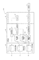
図3に示すように、ワイヤハーネスの製造システム100は、前述のヘッドマウントディスプレイ20と、携帯端末30と、サーバ40とを備えている。
Next, the configuration of the wire harness manufacturing system will be described.
As shown in FIG. 3, the wire
携帯端末30は、ヘッドマウントディスプレイ20を装着した作業者Sが携帯する処理装置である。携帯端末30は、オブジェクト識別部31と、誘導情報取得部32と、誘導位置補正部33と、誘導情報表示部34と、SDメモリーカード等の動画保存部35とを有している。ヘッドマウントディスプレイ20と携帯端末30とは、相互通信によってデータの送受信が可能となっている。
The
サーバ40は、例えば、工場内のサーバルーム等に設置されている。サーバ40は、誘導情報部41と、作業実績情報部42と、を有している。誘導情報部41には、予め作成された誘導情報のデータが格納されている。作業実績情報部42には、作業者Sによる作業の動画などの作業内容のデータが保存されて収集される。携帯端末30とサーバ40とは、相互通信によってデータの送受信が可能となっている。
The
上述した構成を有するワイヤハーネスの製造システム100は、作業者Sによる保持作業および組付作業などの各種の作業を補助すると共に、作業者Sによる保持作業や組付作業などの各種の作業内容を収集するようになっている。
The wire
次いで、ワイヤハーネスの製造システム100による作業の補助および作業内容の収集について、図4に示すフローチャートに沿って説明する。本例では、二つのコネクタ2をコネクタ保持具12に保持させ、これらのコネクタ2の間の電線1をワイヤ係止具11に係止させる保持作業を行う場合について説明する。
Next, work assistance and work content collection by the wire
作業台10において保持作業を行うべく、作業者Sが作業台10を視認すると、作業者Sが装着しているヘッドマウントディスプレイ20のカメラ22が作業台10上に向けられる。このとき、カメラ22によって作業台10が撮影され、その画像信号が携帯端末30のオブジェクト識別部31へ送信される(ステップS01)。
When the worker S visually recognizes the work table 10 to perform the holding work on the work table 10, the
携帯端末30のオブジェクト識別部31では、画像信号に基づき、画像中におけるARオブジェクトを識別する(ステップS02)。具体的には、図5(a)に示すように、オブジェクト識別部31は、画像信号に基づいて、作業台10上のコネクタ保持具12(図5(a)における四角で囲んだコネクタ保持具12)をARオブジェクトとして識別する。
The
携帯端末30のオブジェクト識別部31は、コネクタ保持具12をARオブジェクトとして識別すると、誘導情報取得部32へ識別信号を送信する。誘導情報取得部32は、識別したARオブジェクトに対応する誘導情報を取得すべく、サーバ40の誘導情報部41へ誘導情報取得信号を送信する。これにより、サーバ40では、誘導情報部41から、識別されたARオブジェクトに対応する誘導情報が引き出され、その誘導情報が携帯端末30の誘導位置補正部33へ送信される(ステップS03)。
When the
誘導情報が送信された誘導位置補正部33では、位置補正処理が行われる(ステップS04)。具体的には、誘導情報に基づいて表示する映像の表示角度および縮尺などを、実際のコネクタ保持具12及びワイヤ係止具11に合致するように補正する。そして、誘導位置補正部33で補正された誘導情報が、誘導位置補正部33から誘導情報表示部34に送信される。
In the guidance
その後、誘導情報表示部34から誘導情報表示信号がヘッドマウントディスプレイ20に送信され、ヘッドマウントディスプレイ20のディスプレイ21に誘導情報の映像が表示される。これにより、作業者Sに対する補助が行われる(ステップS05)。具体的には、ディスプレイ21には、図5(b)に示すように、コネクタ2を保持するコネクタ保持具12を囲う丸印および各コネクタ保持具12に保持させるコネクタ2の品番などの誘導表示Aが表示される。
Thereafter, a guidance information display signal is transmitted from the guidance
作業者Sは、誘導表示Aの丸印を視認することにより、二つのコネクタ2を保持させるべきコネクタ保持具12を確認することができる。更に、作業者Sは。誘導表示Aの品番を確認することにより、それぞれのコネクタ2をコネクタ保持具12のどちらに保持させるべきかを確認することができる。
The operator S can confirm the
次いで、ディスプレイ21には、図5(c)に示すように、電線1の配索を促す線状の誘導表示Bが表示される。誘導表示Bは、図5(d)に示すように、一方のコネクタ保持具12からワイヤ係止具11へ向かって徐々に延びる。その後、誘導表示Bは、図5(e)に示すように、ワイヤ係止具11に達すると、図5(f)に示すように折り返され、図5(g)に示すように他方のコネクタ保持具12へ向かって徐々に延び、図5(h)に示すように他方のコネクタ保持具12に達する。なお、誘導表示Bを表示させる変化の速度として、例えば、予め設定した目標の作業速度(タクトタイムから算出した作業速度)が用いられる。
Next, as shown in FIG. 5 (c), a linear guide display B that prompts the user to route the
作業者Sは、誘導表示Bを視認することにより、電線1の配索手順、電線1の配索方向および配索速さを確認することができる。具体的には、作業者Sは、品番522のコネクタ2を、誘導表示Aで品番522が表示された一方のコネクタ保持具12に保持させ、その後、誘導表示Bに従ってワイヤ係止具11へ向かって電線1を配索し、ワイヤ係止具11に電線1を係止させて折り返し、誘導表示Aで品番521が表示された他方のコネクタ保持具12へ向かって配索する。そして、品番521のコネクタ2を、誘導表示Aで品番521が表示された他方のコネクタ保持具12に保持させる。
The worker S can confirm the routing procedure of the
このとき、作業者Sによる保持作業などの作業内容の映像が、ヘッドマウントディスプレイ20のカメラ22によって撮影される(ステップS07)。撮影される映像は、静止画像であっても動画であってもよい。
At this time, an image of work content such as a holding work by the worker S is taken by the
作業内容の画像データは、携帯端末30の動画保存部35へ送信され、動画保存部35に一時的に保存される(ステップS08)。
The image data of the work content is transmitted to the moving
動画保存部35に保存された動画データは、定期的にサーバ40へ送信され、サーバ40の作業実績情報部42に保存される(ステップS09)。これにより、サーバ40には、作業者Sによる保持作業などの作業をカメラ22で撮影した画像が収集されることになる。
The moving image data stored in the moving
次いで、図6を参照しながら、ワイヤハーネスの製造システム100が、電線1を束ねるテープを電線1に巻き付けるテープ巻き作業からなる組付作業を補助する場合について説明する。
Next, a case where the wire
作業者Sがコネクタ保持具12にコネクタ2を保持させ、ワイヤ係止具11に電線1を係止させると、図6(a)に示すように、作業台10上のコネクタ保持具12(図6(a)における四角で囲んだコネクタ保持具12)がARオブジェクトとして識別され、ヘッドマウントディスプレイ20のディスプレイ21に、テープ巻き作業のための誘導情報の映像が表示される。なお、この表示は、例えば、作業者Sがヘッドマウントディスプレイ20等に設けられたボタン等を操作することにより、次なる作業工程の補助を求める信号を携帯端末30に送信することによって開始されてもよい。
When the operator S holds the
具体的には、ディスプレイ21には、電線1へ巻き付けるテープTの巻き付け開始位置と巻き付け終了位置とを指示する破線や文字、並びに、電線1に巻き付けるテープTの巻き付けピッチ長Pを指示する文字および数字などの誘導表示Cが表示される。
Specifically, on the
作業者Sは、誘導表示Cを視認することにより、電線1に対するテープTの巻き付け開始位置及び巻き付け終了位置を確認することができる。更に、作業者Sは、テープTの巻き付けピッチ長Pを確認することができる。
The operator S can confirm the winding start position and the winding end position of the tape T around the
次いで、ディスプレイ21には、図6(b)に示すように、電線1に巻き付けるテープTの映像からなる誘導表示Dが表示される。誘導表示Dは、巻き付け開始位置から表示され、図6(c)から図6(e)に示すように巻き付け終了位置へ向かって徐々に延び、図6(f)に示すように巻き付け終了位置まで延びる。更に、誘導表示Dは、テープTの巻き付け方向及び巻き付け時の重ね代が視覚的に確認できる映像とされている。なお、誘導表示Dを表示させる変化の速度としては、上記同様、予め設定した目標の作業速度とされている。
Next, as shown in FIG. 6B, the
作業者Sは、誘導表示Dを視認することにより、電線1に対して、巻き付け開始位置から巻き付け終了位置まで、指示された巻き付け方向及び巻き付けピッチ長PでテープTを巻き付ける。
By visually recognizing the guidance display D, the operator S winds the tape T around the
以上、説明したように、第1実施形態に係るワイヤハーネスの製造システム100によれば、作業者Sと作業台10との間であって作業者Sの視界中に各作業を補助する情報が表示されるため、従来システム(作業台の背面側から情報を投影する手法)に比べ、それら情報が作業台10上の治具等に隠れることがない。更に、電線1の配索形状に沿った表示形態、及び、付属部品の種別ごとに異なる表示形態にて情報が表示されるため、行うべき作業を作業者Sがより確実に認識できる。
As described above, according to the wire
したがって、第1実施形態に係るワイヤハーネスの製造システム100は、ワイヤハーネスWを製造する各作業を補助する情報を作業者Sに出来る限り確実に認識させることが可能である。
Therefore, the wire
更に、作業者Sは、保持作業を行うとき、誘導表示A,Bに示される順に電線1をワイヤ係止具11などの治具に保持することにより、容易に目標の配索形状をなすように電線1を保持できる。更に、作業者Sは、組付作業を行うとき、誘導表示C,Dに示されるとおりにテープTを巻きつけることにより、容易に設計通りのテープ巻きを行うことができる。よって、ワイヤハーネス製造の作業性を向上できる。
Further, when the worker S performs the holding work, the worker S can easily form the target routing shape by holding the
なお、コルゲートチューブ、グロメット及びキャップなどの付属部品を取り付ける組付作業のように、組み付けの際の手順にさほど注意を要さない作業に対しては、誘導表示として、徐々に表示する表示ではなく瞬時に表示する表示を用いることができる。これにより、付属部品の組付場所を作業者Sへ迅速に確認させることができる。 For work that does not require much attention to the procedure during assembly, such as assembly work that attaches accessories such as corrugated tubes, grommets, and caps, it is not a display that gradually displays as a guidance display. A display that displays instantaneously can be used. As a result, it is possible to prompt the worker S to quickly confirm the assembly location of the accessory parts.
更に、収集部である作業実績情報部42に、作業者Sが行った作業内容の画像を収集するため、作業実績情報部42に収集された各作業の画像に基づき、作業者Sによらず作業効率の低い作業を特定して作業手順を改善する等、ワイヤハーネス製造の作業性を向上できる。
Furthermore, in order to collect the image of the content of the work performed by the worker S in the work
ところで従来システムでは、画像を投影するための装置(プロジェクタ)を作業台の背面側に設置する必要があるため、組立ラインの設計自由度が低下する可能性がある。しかし、ワイヤハーネスの製造システム100は、作業者Sの身体にディスプレイ21を備えたヘッドマウントディスプレイ20が装着されるため、組立ラインの設計自由度には影響がない。よって、より自由度の高い組立ラインを設計できる。
By the way, in the conventional system, since it is necessary to install an apparatus (projector) for projecting an image on the back side of the work table, the design freedom of the assembly line may be lowered. However, in the wire
<第1実施形態の変形例>
次いで、上記第1実施形態に係るワイヤハーネスの製造システム100の変形例について説明する。
<Modification of First Embodiment>
Next, a modification of the wire
図7に示すように、第1実施形態の変形例に係るワイヤハーネスの製造システム100Aは、携帯端末30がキャビティ位置情報取得部36を備え、サーバ40がキャビティ位置情報部43を備えている。
As shown in FIG. 7, in the wire
ワイヤハーネスの製造システム100Aは、作業台10に保持させたコネクタ2に端子を挿し込んで装着する組付作業を補助する。更に、ワイヤハーネスの製造システム100Aにおいても、作業者Sの作業内容を収集する。
The wire
次いで、ワイヤハーネスの製造システム100Aによる作業の補助及び作業内容の収集について、図8に示すフローチャートに沿って説明する。本例では、電線1の端部に接続された端子をコネクタ保持具12に保持させたコネクタ2の所定のキャビティに挿入して装着する場合について説明する。
Next, work assistance and work content collection by the wire
作業台10において組付作業を行うべく、コネクタ保持具12にコネクタ2が保持されている作業台10を作業者Sが視認すると、作業者Sが装着しているヘッドマウントディスプレイ20のカメラ22が作業台10上に向けられる。すると、カメラ22によって作業台10が撮影され、その画像信号が携帯端末30のオブジェクト識別部31へ送信される(ステップS11)。
When the worker S visually recognizes the work table 10 in which the
携帯端末30のオブジェクト識別部31では、画像信号に基づき、画像中におけるARオブジェクトを識別する(ステップS12)。具体的には、図9(a)に示すように、オブジェクト識別部31は、画像信号に基づいて、作業台10上のコネクタ保持具12に保持されたコネクタ2(図9(a)における四角で囲んだコネクタ2)をARオブジェクトとして識別する。コネクタ2は、端子収容室であるキャビティ3を複数有する樹脂製のコネクタハウジング4を備えている。
The
携帯端末30のオブジェクト識別部31は、コネクタ2をARオブジェクトとして識別すると共に、コネクタ2の外観形状に基づいてコネクタ2の種別やキャビティ3の位置、コネクタハウジング4の角度を判別し、誘導情報取得部32へ識別信号を送信する。誘導情報取得部32は、識別したARオブジェクトであるコネクタ2に対応する誘導情報を取得すべく、サーバ40の誘導情報部41へ誘導情報取得信号を送信する。サーバ40では、誘導情報部41から、識別されたARオブジェクトであるコネクタ2に対応する誘導情報が引き出され、その誘導情報が携帯端末30の誘導位置補正部33へ送信される(ステップS13)。
The
更に、携帯端末30のオブジェクト識別部31は、キャビティ位置情報取得部36へ識別信号を送信する。キャビティ位置情報取得部36は、ARオブジェクトとされたコネクタ2の予め設定された基準点に対する端子を挿し込ませる誘導対象のキャビティ3の位置情報を取得すべく、サーバ40のキャビティ位置情報部43へ位置情報取得信号を送信する。サーバ40では、キャビティ位置情報部43から、コネクタ2の誘導対象のキャビティ3の位置情報が引き出され、その位置情報が携帯端末30の誘導位置補正部33へ送信される(ステップS14)。
Further, the
誘導情報及び位置情報が送信された誘導位置補正部33では、位置補正処理が行われる(ステップS15)。具体的には、誘導情報及び位置情報に基づいて表示する映像の表示角度や縮尺を、識別したARオブジェクトである実際のコネクタ2に合致するように補正する。そして、誘導位置補正部33で補正された誘導情報及び位置情報は、誘導位置補正部33から誘導情報表示部34に送信される。
In the guidance
誘導情報表示部34から誘導情報表示信号がヘッドマウントディスプレイ20に送信され、ヘッドマウントディスプレイ20のディスプレイ21に誘導情報の映像が表示され、作業者Sに対する補助が行われる(ステップS16)。具体的には、ディスプレイ21には、図9(b)に示すように、端子を挿入すべきキャビティ3に重なるように、点状の誘導表示Eが表示される。誘導表示Eは、図9(c)に示すように一旦消えたあと、図9(d)に示すように再度表示され、点消灯が繰り返される。これにより、誘導表示Eは、端子を挿入すべきキャビティ3に重なる位置で点滅して表示される。
A guidance information display signal is transmitted from the guidance
作業者Sは、誘導表示Eを視認することにより、コネクタハウジング4のどのキャビティ3に端子を挿入すべきかを確認し、確認したキャビティ3に端子を挿入して装着する。
The worker S visually confirms the guidance display E to confirm in which
なお、誘導表示Eの表示色は、対象のキャビティ3へ挿し込む端子が接続された電線1の被覆色に合わせることが好ましい。これにより、誘導表示Eの表示色と同じ被覆色の電線1に接続された端子を対象のキャビティ3へ正確に誘導させて作業者Sに挿し込ませることができる。
In addition, it is preferable to match | combine the display color of the guidance display E with the coating | coated color of the
作業者Sによる組付作業などの作業内容の映像がヘッドマウントディスプレイ20のカメラ22によって撮影される(ステップS17)。
An image of work contents such as assembly work by the worker S is taken by the
作業内容の動画からなる画像データは、携帯端末30の動画保存部35へ送信され、動画保存部35に一時的に保存される(ステップS18)。
The image data including the moving image of the work content is transmitted to the moving
動画保存部35に保存された動画データは、定期的にサーバ40へ送信され、サーバ40の作業実績情報部42に保存される(ステップS19)。これにより、サーバ40には、作業者Sによる組付作業などの作業をカメラ22で撮影した画像が収集される。
The moving image data stored in the moving
以上、説明したように、第1実施形態の変形例に係るワイヤハーネスの製造システム100Aによれば、組付作業を行うとき、誘導表示Eに示される通りに端子収容室であるキャビティ3に端子を挿入すれば、容易に設計通りの端子付き電線を製造できる。
As described above, according to the wire
<第2実施形態>
次いで、第2実施形態に係るワイヤハーネスの製造システムについて説明する。なお、第1実施形態と同一構成部分については、同一符号を付して説明を省略する。
Second Embodiment
Next, a wire harness manufacturing system according to a second embodiment will be described. In addition, about the same component as 1st Embodiment, the same code | symbol is attached | subjected and description is abbreviate | omitted.
図10に示すように、第2実施形態に係るワイヤハーネスの製造システムでは、作業台10に、ARマーカーMが付されている。これらのARマーカーMは、ワイヤ係止具11及びコネクタ保持具12などの各種の冶具の近傍に配置されている。
As shown in FIG. 10, the AR marker M is attached to the work table 10 in the wire harness manufacturing system according to the second embodiment. These AR markers M are arranged in the vicinity of various jigs such as the
図11に示すように、第2実施形態に係るワイヤハーネスの製造システム200は、第1実施形態に係るワイヤハーネスの製造システム100に対して、携帯端末30の構成が異なる。具体的には、携帯端末30が、オブジェクト識別部31に代えて、ARマーカー識別部31Aを備えている。
As illustrated in FIG. 11, the wire
次いで、ワイヤハーネスの製造システム200による作業の補助及び作業内容の収集について、図12に示すフローチャートに沿って説明する。本例では、二つのコネクタ2をコネクタ保持具12に保持させ、これらのコネクタ2の間の電線1をワイヤ係止具11に係止させる保持作業を行う場合について説明する。
Next, work assistance and work content collection by the wire
作業台10において保持作業を行うべく、作業者Sが作業台10を視認すると、作業者Sが装着しているヘッドマウントディスプレイ20のカメラ22が作業台10上に向けられる。すると、カメラ22によって作業台10が撮影され、その画像信号が携帯端末30のオブジェクト識別部31へ送信される(ステップS21)。
When the worker S visually recognizes the work table 10 to perform the holding work on the work table 10, the
携帯端末30のARマーカー識別部31Aでは、画像信号に基づいて、画像中におけるARマーカーMを識別する(ステップS22)。具体的には、図13(a)に示すように、ARマーカー識別部31Aは、画像信号に基づき、作業台10上のコネクタ保持具12の近傍のARマーカーM(図13(a)における四角で囲んだARマーカーM)を識別する。
The AR
携帯端末30のARマーカー識別部31Aは、ARマーカーMを識別すると、誘導情報取得部32へ識別信号を送信する。誘導情報取得部32は、識別したARマーカーMに対応する誘導情報を取得すべく、サーバ40の誘導情報部41へ誘導情報取得信号を送信する。サーバ40では、誘導情報部41から、識別されたARマーカーに対応する誘導情報が引き出され、その誘導情報が携帯端末30の誘導位置補正部33へ送信される(ステップS23)。
When the AR
誘導情報が送信された誘導位置補正部33では、位置補正処理が行われる(ステップS24)。具体的には、誘導情報に基づいて表示する映像の表示角度や縮尺を、実際のコネクタ保持具12及びワイヤ係止具11に合致するように補正する。誘導位置補正部33で補正された誘導情報は、誘導位置補正部33から誘導情報表示部34に送信される。
In the guidance
誘導情報表示部34から誘導情報表示信号がヘッドマウントディスプレイ20に送信され、ヘッドマウントディスプレイ20のディスプレイ21に誘導情報の映像が表示され、作業者Sに対する補助が行われる(ステップS25)。具体的には、ディスプレイ21には、図13(b)に示すように、コネクタ2を保持するコネクタ保持具12を囲う丸印および各コネクタ保持具12に保持させるコネクタ2の品番などの誘導表示Fが表示される。
A guidance information display signal is transmitted from the guidance
作業者Sは、誘導表示Fの丸印を視認することにより、二つのコネクタ2を保持させるコネクタ保持具12を確認することができる。更に、作業者Sは、誘導表示Fの品番を確認することにより、それぞれのコネクタ2をコネクタ保持具12のどちらに保持させるべきかを確認することができる。
The worker S can confirm the
次いで、ディスプレイ21には、図13(c)に示すように、電線1の配索を促す線状の誘導表示Gが表示される。誘導表示Gは、図13(d)に示すように、一方のコネクタ保持具12からワイヤ係止具11へ向かって徐々に延びる。その後、誘導表示Gは、図13(e)に示すようにワイヤ係止具11に達すると、図13(f)に示すように折り返され、図13(g)に示すように他方のコネクタ保持具12へ向かって徐々に延び、図13(h)に示すように他方のコネクタ保持具12に達する。なお、誘導表示Gを表示させる変化の速度としては、予め設定した目標の作業速度とされている。
Next, as shown in FIG. 13C, a linear guidance display G that prompts the user to route the
作業者Sは、誘導表示Gを視認することにより、電線1の配索手順、電線1の配索方向及び配索速さを確認することができる。具体的には、作業者Sは、品番522のコネクタ2を、誘導表示Fで品番522が表示された一方のコネクタ保持具12に保持させ、その後、誘導表示Gに従ってワイヤ係止具11へ向かって電線1を配索し、ワイヤ係止具11に電線1を係止させて折り返し、誘導表示Fで品番521が表示された他方のコネクタ保持具12へ向かって配索する。そして、品番521のコネクタ2を、誘導表示Fで品番521が表示された他方のコネクタ保持具12に保持させる。
The worker S can confirm the routing procedure of the
作業者Sによる保持作業などの作業内容の映像がヘッドマウントディスプレイ20のカメラ22によって撮影される(ステップS27)。
An image of work content such as holding work by the worker S is taken by the
作業内容の動画からなる画像データは、携帯端末30の動画保存部35へ送信され、動画保存部35に一時的に保存される(ステップS28)。
The image data including the moving image of the work content is transmitted to the moving
動画保存部35に保存された動画データは、定期的にサーバ40へ送信され、サーバ40の作業実績情報部42に保存される(ステップS29)。これにより、サーバ40には、作業者Sによる保持作業などの作業をカメラ22で撮影した画像が収集される。
The moving image data stored in the moving
このように、第2実施形態に係るワイヤハーネスの製造システム200の場合も、作業者Sと作業台10との間であって作業者Sの視界中に各作業を補助する情報が表示されるため、従来システム(作業台の背面側から情報を投影する手法)に比べ、それら情報が作業台10上の治具等に隠れることがない。更に、電線1の配索形状に沿った表示形態、及び、付属部品の種別ごとに異なる表示形態にて情報が表示されるため、行うべき作業を作業者Sがより確実に認識できる。
Thus, also in the case of the wire
したがって、第2実施形態に係るワイヤハーネスの製造システム200は、ワイヤハーネスWを製造する各作業を補助する情報を作業者Sに出来る限り確実に認識させることが可能である。
Therefore, the wire
更に、作業者Sは、保持作業や組付作業を行うとき、誘導表示に従って作業することで、容易に目標の配索形状をなすように電線1を保持でき、また、容易に設計通りに付属部品を組み付けることができる。よって、ワイヤハーネス製造の作業性を向上できる。
Furthermore, the worker S can easily hold the
<第2実施形態の変形例>
次いで、上記第2実施形態に係るワイヤハーネスの製造システム200の変形例について説明する。
<Modification of Second Embodiment>
Next, a modification of the wire
図14に示すように、第2実施形態の変形例に係るワイヤハーネスの製造システム200Aは、携帯端末30がキャビティ位置情報取得部36を備え、サーバ40がキャビティ位置情報部43を備えている。
As shown in FIG. 14, in the wire
ワイヤハーネスの製造システム200Aは、作業台10に保持させたコネクタ2に端子を挿し込んで装着する組付作業を補助する。また、ワイヤハーネスの製造システム200Aにおいても、作業者Sの作業内容を収集する。
The wire
次いで、ワイヤハーネスの製造システム200Aによる作業の補助及び作業内容の収集について、図15に示すフローチャートに沿って説明する。本例では、電線1の端部に接続された端子をコネクタ保持具12に保持させたコネクタ2の所定のキャビティに挿入して装着する場合について説明する。
Next, work assistance and work content collection by the wire harness manufacturing system 200A will be described with reference to the flowchart shown in FIG. In this example, a case will be described in which a terminal connected to the end of the
作業台10において組付作業を行うべく、コネクタ保持具12にコネクタ2が保持されている作業台10を作業者Sが視認すると、作業者Sが装着しているヘッドマウントディスプレイ20のカメラ22が作業台10上に向けられる。すると、カメラ22によって作業台10が撮影され、その画像信号が携帯端末30のARマーカー識別部31Aへ送信される(ステップS31)。
When the worker S visually recognizes the work table 10 in which the
携帯端末30のARマーカー識別部31Aでは、画像信号に基づいて、画像中におけるARマーカーMを識別する(ステップS32)。具体的には、図16(a)に示すように、ARマーカー識別部31Aは、画像信号に基づいて、作業台10上のコネクタ保持具12の近傍に付されたARマーカーM(図16(a)における四角で囲んだARマーカーM)を識別する。
The AR
携帯端末30のARマーカー識別部31Aは、ARマーカーMを識別するとともに、コネクタ保持具12に保持されたコネクタ2の種別やキャビティ3の位置、コネクタハウジング4の角度を判別し、誘導情報取得部32へ識別信号を送信する。誘導情報取得部32は、識別したARマーカーMに対応する誘導情報を取得すべく、サーバ40の誘導情報部41へ誘導情報取得信号を送信する。サーバ40では、誘導情報部41から、識別されたARマーカーMに対応する誘導情報が引き出され、その誘導情報が携帯端末30の誘導位置補正部33へ送信される(ステップS33)。
The AR
更に、携帯端末30のARマーカー識別部31Aは、キャビティ位置情報取得部36へ識別信号を送信する。キャビティ位置情報取得部36は、コネクタ2の予め設定された基準点に対する端子を挿し込ませる誘導対象のキャビティ3の位置情報を取得すべく、サーバ40のキャビティ位置情報部43へ位置情報取得信号を送信する。サーバ40では、キャビティ位置情報部43から、コネクタ2の誘導対象のキャビティ3の位置情報が引き出され、その位置情報が携帯端末30の誘導位置補正部33へ送信される(ステップS34)。
Furthermore, the AR
誘導情報及び位置情報が送信された誘導位置補正部33では、位置補正処理が行われる(ステップS35)。具体的には、誘導情報及び位置情報に基づいて表示する映像の表示角度や縮尺を、実際のコネクタ2に合致するように補正する。そして、誘導位置補正部33で補正された誘導情報及び位置情報は、誘導位置補正部33から誘導情報表示部34に送信される。
In the guidance
誘導情報表示部34から誘導情報表示信号がヘッドマウントディスプレイ20に送信され、ヘッドマウントディスプレイ20のディスプレイ21に誘導情報の映像が表示され、作業者Sに対する補助が行われる(ステップS36)。
A guidance information display signal is transmitted from the guidance
具体的には、ディスプレイ21には、図16(b)に示すように、端子を挿入すべきキャビティ3に重なるように、点状の誘導表示Hが表示される。誘導表示Hは、図16(c)に示すように、一旦消えたあと、図16(d)に示すように、再度表示され、点消灯が繰り返される。これにより、誘導表示Hは、端子を挿入すべきキャビティ3に重なる位置で点滅して表示される。
Specifically, as shown in FIG. 16B, a dotted guide display H is displayed on the
作業者Sは、誘導表示Hを視認することにより、コネクタハウジング4のどのキャビティ3に端子を挿入すべきかを確認し、確認したキャビティ3に端子を挿入して装着する。
The worker S visually confirms the guidance display H to confirm in which
なお、誘導表示Hの表示色は、対象のキャビティ3へ挿し込む端子が接続された電線1の被覆色に合わせることが好ましい。このようにすれば、誘導表示Hの表示色と同じ被覆色の電線1に接続された端子を対象のキャビティ3へ正確に誘導させて作業者Sに挿し込ませることができる。
In addition, it is preferable to match | combine the display color of the induction | guidance | derivation display H with the coating color of the
作業者Sによる組付作業などの作業内容の映像がヘッドマウントディスプレイ20のカメラ22によって撮影される(ステップS37)。
An image of work contents such as assembly work by the worker S is taken by the
作業内容の動画からなる画像データは、携帯端末30の動画保存部35へ送信され、動画保存部35に一時的に保存される(ステップS38)。
The image data composed of the moving image of the work content is transmitted to the moving
動画保存部35に保存された動画データは、定期的にサーバ40へ送信され、サーバ40の作業実績情報部42に保存される(ステップS39)。これにより、サーバ40には、作業者Sによる組付作業などの作業をカメラ22で撮影した画像が収集される。
The moving image data stored in the moving
このように、第2実施形態の変形例に係るワイヤハーネスの製造システム200Aによれば、組付作業を行うとき、誘導表示Hに示される通りに端子収容室であるキャビティ3に端子を挿入すれば、容易に設計通りの端子付き電線を製造できる。
As described above, according to the wire harness manufacturing system 200A according to the modification of the second embodiment, when the assembly work is performed, the terminal is inserted into the
なお、上記ワイヤハーネスの製造システム100,100A,200,200Aでは、作業者Sの作業に配索違いや組み付け違いなどの誤作業があり、誘導表示と実際の作業とが大きく相違しているときに、ディスプレイ21に誤作業であることの警告を表示させる。これにより、作業者Sによる誤作業を抑えることができる。
In the wire
更に、ディスプレイ21には、例えば、電線1等に組み付けるテープTやコルゲートチューブ等の付属部品の実物の立体映像を表示させても良い。このようにすれば、作業者Sに対して、電線1に組み付ける付属部品を視覚的に迅速かつ容易に認識させることができる。
Further, for example, the
更に、ディスプレイ21には、作業台10上におけるワイヤ係止具11やコネクタ保持具12などの冶具のうちの使用しない治具を示す表示や交換が必要な治具を示す表示を映しても良い。
Further, the
更に、ディスプレイ21には、画像の表示と併せて、作業内容や作業手順などを指示するメッセージ、組み付ける付属部品の品名などを表示させても良い。
Further, the
なお、作業台10には、カメラ22で撮影された画像の位置を識別するための模様や図面などからなる位置情報を付しても良い。これにより、作業台10の位置情報に基づいて、カメラ22で撮影された位置を正確に特定し、その位置における誘導情報を迅速に引き出すことができる。
Note that the work table 10 may be provided with position information including a pattern or a drawing for identifying the position of an image captured by the
更に、作業の終了を認識させるためのスイッチを携帯端末30等に設け、作業の終了時に作業者Sに操作させても良い。また、作業の終了を認識させるマークを作業台10や治具等に付しておき、このマークを識別することで作業の終了を認識させても良い。
Furthermore, a switch for recognizing the end of the work may be provided on the
なお、複数の作業者Sが同時に作業する場合には、各作業者Sが装着する携帯端末30に固有のIDを割り当てて区別する。このようにすれば、各作業者Sへ誘導情報を混乱なく提供することができる。
When a plurality of workers S work at the same time, a unique ID is assigned to the
<他の態様>
なお、本発明は上記各実施形態に限定されることはなく、本発明の範囲内において種々の変形例を採用できる。例えば、本発明は、上述した実施形態に限定されるものではなく、適宜、変形、改良、等が可能である。その他、上述した実施形態における各構成要素の材質、形状、寸法、数、配置箇所、等は本発明を達成できるものであれば任意であり、限定されない。
<Other aspects>
In addition, this invention is not limited to said each embodiment, A various modification is employable within the scope of the present invention. For example, the present invention is not limited to the above-described embodiments, and modifications, improvements, and the like can be made as appropriate. In addition, the material, shape, dimensions, number, arrangement location, and the like of each component in the above-described embodiment are arbitrary and are not limited as long as the present invention can be achieved.
例えば、複数の作業者Sによる作業を管理するために、各作業者Sの作業時間の情報を収集し、この収集した作業時間情報に基づいて、作業者Sによる各工程での作業の改善などに活用する作業管理機能を付加したシステムとしても良い。 For example, in order to manage the work by a plurality of workers S, information on the work time of each worker S is collected, and based on the collected work time information, the work of each step by the worker S is improved. It is good also as a system which added the work management function utilized for.
ここで、この作業者Sの作業を管理する作業管理機能を付加したシステムについて説明する。このシステムは、各作業者Sが携帯するRFID(Radio Frequency Iidentifier)タグと、製造ラインにおける工程毎に設けられたアンテナからなる受信部と、受信部からの受信データを収集する収集部とを備えている。 Here, a system to which a work management function for managing the work of the worker S is added will be described. This system includes an RFID (Radio Frequency Identifier) tag carried by each worker S, a receiving unit including an antenna provided for each process in the production line, and a collecting unit that collects reception data from the receiving unit. ing.
このシステムでは、製造ラインの受信部が受信したRFIDタグからの信号の強度等に基づき、作業者Sがどの工程の受信部の付近で作業しているかを判定し、その受信部付近に滞在している時間を収集部で収集する。そして、この収集部で収集した時間を、各作業者Sがその工程にて行った作業時間とする。 In this system, based on the strength of the signal from the RFID tag received by the receiving unit of the production line, the worker S determines which process the receiving unit is working in, and stays in the vicinity of the receiving unit. The time that is collected is collected by the collection unit. And let the time collected in this collection part be work time which each worker S performed in the process.
作業者Sの勤務時間の終了後、システムは、各作業者Sの作業時間及び各作業者Sの各工程における作業時間を集計する。更に、システムは、製造ラインにおける各機械の作動状況およびワイヤハーネスWの生産本数等の実績を収集し、各作業者Sの日報を作成する。 After the end of the working hours of the worker S, the system adds up the working time of each worker S and the working time in each process of each worker S. Furthermore, the system collects the results of operation of each machine in the production line, the number of wire harnesses W produced, and the like, and creates a daily report for each worker S.
このように、作業管理機能を付加したシステムによれば、製造ラインにおいて、作業者Sがどの工程の作業を何時間行ったかなどの作業時間情報を自動で集計して日報を作成することができる。これにより、原価計算、能率の把握による工程の改善活動などを迅速かつ正確に行うことができ、製造コストの低減及び生産性の向上を図ることができる。 Thus, according to the system to which the work management function is added, the daily report can be created by automatically counting work time information such as how many hours of work the worker S has performed in the production line. . As a result, it is possible to quickly and accurately perform process improvement activities by cost accounting and grasping efficiency, and it is possible to reduce manufacturing costs and improve productivity.
更に、作業者Sがどの工程の受信部の付近で作業しているかの判定結果を、上述した携帯端末30でのオブジェクト識別などの精度向上に用いてもよい。これにより、作業者Sに対し、より精度の高い誘導表示を提供できる。
Furthermore, the determination result of which process the worker S is working in near the receiving unit may be used for improving the accuracy of object identification or the like on the
ここで、上述した本発明に係るワイヤハーネスの製造システムの実施形態の特徴をそれぞれ以下(1)〜(4)に簡潔に纏めて列記する。
(1)
電線(1)及び複数の付属部品(2)を有するワイヤハーネス(W)の製造システムであって、
前記電線(1)が所定の配索形状をなすように保持する保持作業及び前記電線(1)と前記複数の付属部品(2)とを組み付ける組付作業の少なくとも一方を作業者(S)が行うための作業台(10)と、前記作業者(S)と前記作業台(10)との間であって前記作業者(S)の視界中に前記保持作業及び前記組付作業を補助する情報を表示する補助装置(20)と、を備え、
前記補助装置(20)は、
前記作業台(10)を撮影する撮影部(22)と、前記撮影部(22)が撮影した画像に基づいて定められた前記情報を前記配索形状に沿った表示形態又は前記付属部品(2)の種別ごとに異なる表示形態にて表示する表示部(21)と、を有する、
ワイヤハーネスの製造システム。
(2)
上記(1)に記載の製造システムにおいて、
前記補助装置(20)が、
前記保持作業を補助するための前記情報として、前記配索形状に対応して前記作業台(10)上に配置された複数の治具(11,12)を前記電線(1)の保持の順に繋ぐように延びる誘導表示(A,B)を行い、
前記組付作業を補助するための前記情報として、前記付属部品(2)が複数の端子収容室(3)を有するコネクタハウジング(4)である場合、端子を挿入すべき前記端子収容室(3)を表す誘導表示(E)を行い、前記付属部品が前記電線(1)を束ねるテープ(T)である場合、前記テープ(T)を巻き付ける位置及び前記テープ(T)の巻き付けピッチ長(P)を表す誘導表示(C,D)を行う、
ワイヤハーネスの製造システム。
(3)
上記(1)又は上記(2)に記載の製造システムにおいて、
前記保持作業及び前記組付作業を前記撮影部(22)によって撮影した画像を収集する収集部(42)、を更に備えた、
ワイヤハーネスの製造システム。
(4)
上記(1)〜上記(3)の何れか一つに記載の製造システムにおいて、
前記補助装置(20)が、
前記作業者(S)の視線上に前記表示部(21)が位置するように前記作業者(S)の身体に装着される、
ワイヤハーネスの製造システム。
Here, the features of the embodiment of the above-described wire harness manufacturing system according to the present invention are summarized and listed in the following (1) to (4), respectively.
(1)
A manufacturing system of a wire harness (W) having an electric wire (1) and a plurality of accessory parts (2),
An operator (S) performs at least one of a holding operation for holding the electric wire (1) so as to form a predetermined wiring shape and an assembling operation for assembling the electric wire (1) and the plurality of accessory parts (2). The holding work and the assembling work are assisted between the work table (10) to be performed and the worker (S) and the work table (10) in the field of view of the worker (S). An auxiliary device (20) for displaying information,
The auxiliary device (20)
A photographing unit (22) for photographing the workbench (10), and the information determined based on the image photographed by the photographing unit (22) according to the display form or the accessory (2 And a display unit (21) for displaying in a different display form for each type of
Wire harness manufacturing system.
(2)
In the manufacturing system according to (1) above,
The auxiliary device (20)
As the information for assisting the holding operation, a plurality of jigs (11, 12) arranged on the work table (10) corresponding to the routing shape are arranged in the order of holding the electric wire (1). We perform guidance display (A, B) extending so as to connect,
As the information for assisting the assembly work, when the accessory part (2) is a connector housing (4) having a plurality of terminal accommodating chambers (3), the terminal accommodating chamber (3) into which a terminal is to be inserted. ), And when the accessory is a tape (T) for bundling the electric wire (1), a position where the tape (T) is wound and a winding pitch length (P) of the tape (T) ) To display guidance (C, D).
Wire harness manufacturing system.
(3)
In the manufacturing system according to (1) or (2) above,
A collecting unit (42) for collecting images obtained by photographing the holding operation and the assembling operation by the photographing unit (22);
Wire harness manufacturing system.
(4)
In the manufacturing system according to any one of (1) to (3) above,
The auxiliary device (20)
It is mounted on the body of the worker (S) so that the display unit (21) is positioned on the line of sight of the worker (S).
Wire harness manufacturing system.
1 電線
2 コネクタ(付属部品)
3 キャビティ(端子収容室)
4 コネクタハウジング
10 作業台
11 ワイヤ係止具(治具)
12 コネクタ保持具(治具)
20 ヘッドマウントディスプレイ(補助装置)
21 ディスプレイ(表示部)
22 カメラ(撮影部)
42 作業実績情報部(収集部)
100,100A,200,200A ワイヤハーネスの製造システム
A,B,C,D,E,F,G,H 誘導表示
S 作業者
P ピッチ長
T テープ(付属部品)
W ワイヤハーネス
1
3 Cavity (terminal accommodation chamber)
4
12 Connector holder (jig)
20 Head mounted display (auxiliary device)
21 Display (display unit)
22 Camera (shooting unit)
42 Work results information section (collection section)
100, 100A, 200, 200A Wire harness manufacturing system A, B, C, D, E, F, G, H Guide display S Worker P Pitch length T Tape (accessory)
W wire harness
Claims (4)
前記電線が所定の配索形状をなすように保持する保持作業及び前記電線と前記複数の付属部品とを組み付ける組付作業の少なくとも一方を作業者が行うための作業台と、前記作業者と前記作業台との間であって前記作業者の視界中に前記保持作業及び前記組付作業を補助する情報を表示する補助装置と、を備え、
前記補助装置は、
前記作業台を撮影する撮影部と、前記撮影部が撮影した画像に基づいて定められた前記情報を前記配索形状に沿った表示形態又は前記付属部品の種別ごとに異なる表示形態にて表示する表示部と、を有する、
ワイヤハーネスの製造システム。 A wire harness manufacturing system having an electric wire and a plurality of accessory parts,
A workbench for an operator to perform at least one of a holding operation for holding the electric wire so as to form a predetermined wiring shape and an assembling operation for assembling the electric wire and the plurality of accessory parts, the operator, An auxiliary device that displays information for assisting the holding work and the assembly work between the work table and the field of view of the worker;
The auxiliary device is
An image capturing unit that captures the work table and the information determined based on the image captured by the image capturing unit are displayed in a display form along the routing shape or in a different display form for each type of the accessory part. A display unit;
Wire harness manufacturing system.
前記補助装置が、
前記保持作業を補助するための前記情報として、前記配索形状に対応して前記作業台上に配置された複数の治具を前記電線の保持の順に繋ぐように延びる誘導表示を行い、
前記組付作業を補助するための前記情報として、前記付属部品が複数の端子収容室を有するコネクタハウジングである場合、端子を挿入すべき前記端子収容室を表す誘導表示を行い、前記付属部品が前記電線を束ねるテープである場合、前記テープを巻き付ける位置及び前記テープの巻き付けピッチ長を表す誘導表示を行う、
ワイヤハーネスの製造システム。 The manufacturing system according to claim 1,
The auxiliary device is
As the information for assisting the holding work, performing a guidance display extending so as to connect a plurality of jigs arranged on the workbench corresponding to the routing shape in the order of holding the electric wire,
As the information for assisting the assembling work, when the accessory is a connector housing having a plurality of terminal accommodating chambers, a guidance display representing the terminal accommodating chamber into which a terminal is to be inserted is performed. In the case of a tape that bundles the electric wires, a guidance display indicating a position where the tape is wound and a winding pitch length of the tape is performed.
Wire harness manufacturing system.
前記保持作業及び前記組付作業を前記撮影部によって撮影した画像を収集する収集部、を更に備えた、
ワイヤハーネスの製造システム。 In the manufacturing system according to claim 1 or 2,
A collecting unit for collecting images obtained by photographing the holding work and the assembling work by the photographing unit;
Wire harness manufacturing system.
前記補助装置が、
前記作業者の視線上に前記表示部が位置するように前記作業者の身体に装着される、
ワイヤハーネスの製造システム。 In the manufacturing system according to any one of claims 1 to 3,
The auxiliary device is
Attached to the worker's body so that the display unit is positioned on the operator's line of sight,
Wire harness manufacturing system.
Priority Applications (1)
| Application Number | Priority Date | Filing Date | Title |
|---|---|---|---|
| JP2016142658A JP2018014218A (en) | 2016-07-20 | 2016-07-20 | System for producing wire harness |
Applications Claiming Priority (1)
| Application Number | Priority Date | Filing Date | Title |
|---|---|---|---|
| JP2016142658A JP2018014218A (en) | 2016-07-20 | 2016-07-20 | System for producing wire harness |
Publications (1)
| Publication Number | Publication Date |
|---|---|
| JP2018014218A true JP2018014218A (en) | 2018-01-25 |
Family
ID=61020394
Family Applications (1)
| Application Number | Title | Priority Date | Filing Date |
|---|---|---|---|
| JP2016142658A Abandoned JP2018014218A (en) | 2016-07-20 | 2016-07-20 | System for producing wire harness |
Country Status (1)
| Country | Link |
|---|---|
| JP (1) | JP2018014218A (en) |
Cited By (6)
| Publication number | Priority date | Publication date | Assignee | Title |
|---|---|---|---|---|
| JP2019133499A (en) * | 2018-02-01 | 2019-08-08 | 日立金属株式会社 | Design support method for wiring harness |
| JP2020095969A (en) * | 2020-02-27 | 2020-06-18 | 株式会社オートネットワーク技術研究所 | Wiring member |
| JPWO2020250928A1 (en) * | 2019-06-11 | 2020-12-17 | ||
| CN113363861A (en) * | 2021-05-10 | 2021-09-07 | 中航西安飞机工业集团股份有限公司 | High-precision planar liquid crystal display wiring equipment and wiring method |
| US11710928B2 (en) | 2018-09-19 | 2023-07-25 | Autonetworks Technologies, Ltd. | Wiring member |
| JP2024104819A (en) * | 2023-01-25 | 2024-08-06 | 三菱電機ビルソリューションズ株式会社 | Wiring work support system and wiring work support method |
Citations (4)
| Publication number | Priority date | Publication date | Assignee | Title |
|---|---|---|---|---|
| JPH09147641A (en) * | 1995-11-24 | 1997-06-06 | Yazaki Corp | Harness manufacturing method and guidance device |
| JP2000137822A (en) * | 1998-04-08 | 2000-05-16 | Trisen Systems Inc | Actuality emphasis system |
| JP2012152016A (en) * | 2011-01-19 | 2012-08-09 | Mitsubishi Electric Corp | Cable connection work support apparatus |
| JP2013104747A (en) * | 2011-11-11 | 2013-05-30 | Nippon Telegr & Teleph Corp <Ntt> | Operation position guidance device and guidance method therefor |
-
2016
- 2016-07-20 JP JP2016142658A patent/JP2018014218A/en not_active Abandoned
Patent Citations (4)
| Publication number | Priority date | Publication date | Assignee | Title |
|---|---|---|---|---|
| JPH09147641A (en) * | 1995-11-24 | 1997-06-06 | Yazaki Corp | Harness manufacturing method and guidance device |
| JP2000137822A (en) * | 1998-04-08 | 2000-05-16 | Trisen Systems Inc | Actuality emphasis system |
| JP2012152016A (en) * | 2011-01-19 | 2012-08-09 | Mitsubishi Electric Corp | Cable connection work support apparatus |
| JP2013104747A (en) * | 2011-11-11 | 2013-05-30 | Nippon Telegr & Teleph Corp <Ntt> | Operation position guidance device and guidance method therefor |
Cited By (9)
| Publication number | Priority date | Publication date | Assignee | Title |
|---|---|---|---|---|
| JP2019133499A (en) * | 2018-02-01 | 2019-08-08 | 日立金属株式会社 | Design support method for wiring harness |
| JP7021547B2 (en) | 2018-02-01 | 2022-02-17 | 日立金属株式会社 | Wire harness design support method |
| US11710928B2 (en) | 2018-09-19 | 2023-07-25 | Autonetworks Technologies, Ltd. | Wiring member |
| JPWO2020250928A1 (en) * | 2019-06-11 | 2020-12-17 | ||
| JP7283541B2 (en) | 2019-06-11 | 2023-05-30 | 日本電気株式会社 | CABLE CONNECTION SUPPORT SYSTEM, CABLE CONNECTION SUPPORT METHOD, AND CABLE CONNECTION SUPPORT PROGRAM |
| JP2020095969A (en) * | 2020-02-27 | 2020-06-18 | 株式会社オートネットワーク技術研究所 | Wiring member |
| JP7279666B2 (en) | 2020-02-27 | 2023-05-23 | 株式会社オートネットワーク技術研究所 | Wiring material |
| CN113363861A (en) * | 2021-05-10 | 2021-09-07 | 中航西安飞机工业集团股份有限公司 | High-precision planar liquid crystal display wiring equipment and wiring method |
| JP2024104819A (en) * | 2023-01-25 | 2024-08-06 | 三菱電機ビルソリューションズ株式会社 | Wiring work support system and wiring work support method |
Similar Documents
| Publication | Publication Date | Title |
|---|---|---|
| JP2018014218A (en) | System for producing wire harness | |
| JP4996138B2 (en) | Wire harness assembly support device, wire harness assembly support unit, and wire harness assembly support method | |
| US10566771B2 (en) | Method for mounting electric switching systems and assembly support device for simplifying the assembly of such switching systems | |
| JP2010003190A (en) | Maintenance system | |
| EP1413917A2 (en) | Finder, marker presentation member, and presentation method of positioning marker for calibration photography | |
| US10679420B2 (en) | Augmented reality (AR) remote vehicle assistance | |
| JP5214511B2 (en) | Work process management system | |
| CN109118515B (en) | Video tracking method and device for power equipment | |
| CN108154472B (en) | Parking space visual detection method and system integrating navigation information | |
| JP6375633B2 (en) | Vehicle periphery image display device and vehicle periphery image display method | |
| JP2019079144A (en) | Work support system, imaging device, wearable device, and work support method | |
| WO2008068837A1 (en) | Traffic situation display method, traffic situation display system, vehicle-mounted device, and computer program | |
| JP2016192135A (en) | Image acquisition system for processing electric wire group | |
| JP2007306761A (en) | Method of outfitting wire harness branching part with protector, and branching structure of wiring harness | |
| CN110883775B (en) | Human-machine interaction system and human-machine collaboration system of single-arm live-working robot | |
| EP2469467A1 (en) | An integrated method for camera planning and positioning | |
| JP2017152155A (en) | Wire harness manufacturing system and wire harness manufacturing method | |
| KR101764155B1 (en) | System for managing optical fiber line number | |
| JP6445935B2 (en) | Work support device, work support method, and work support program | |
| CN216002443U (en) | Mounting bracket equipment of vehicle-mounted camera | |
| JP2011119065A (en) | Wire harness assembling device, and wire harness assembling method | |
| CN113093740A (en) | Parameter calibration method, system, device and equipment | |
| CN112740339B (en) | Wiring components | |
| JP2002204521A (en) | Method of assembling wire harness and structure of assembling part | |
| JP2011249038A (en) | Wiring harness and assembling method thereof |
Legal Events
| Date | Code | Title | Description |
|---|---|---|---|
| A621 | Written request for application examination |
Free format text: JAPANESE INTERMEDIATE CODE: A621 Effective date: 20190617 |
|
| A977 | Report on retrieval |
Free format text: JAPANESE INTERMEDIATE CODE: A971007 Effective date: 20200520 |
|
| A131 | Notification of reasons for refusal |
Free format text: JAPANESE INTERMEDIATE CODE: A131 Effective date: 20200616 |
|
| A762 | Written abandonment of application |
Free format text: JAPANESE INTERMEDIATE CODE: A762 Effective date: 20200907 |