JP6191644B2 - Vehicle speed limiter - Google Patents
Vehicle speed limiter Download PDFInfo
- Publication number
- JP6191644B2 JP6191644B2 JP2015065174A JP2015065174A JP6191644B2 JP 6191644 B2 JP6191644 B2 JP 6191644B2 JP 2015065174 A JP2015065174 A JP 2015065174A JP 2015065174 A JP2015065174 A JP 2015065174A JP 6191644 B2 JP6191644 B2 JP 6191644B2
- Authority
- JP
- Japan
- Prior art keywords
- driving force
- upper limit
- vehicle speed
- value
- acceleration
- Prior art date
- Legal status (The legal status is an assumption and is not a legal conclusion. Google has not performed a legal analysis and makes no representation as to the accuracy of the status listed.)
- Active
Links
Images

Classifications
-
- F—MECHANICAL ENGINEERING; LIGHTING; HEATING; WEAPONS; BLASTING
- F02—COMBUSTION ENGINES; HOT-GAS OR COMBUSTION-PRODUCT ENGINE PLANTS
- F02D—CONTROLLING COMBUSTION ENGINES
- F02D41/00—Electrical control of supply of combustible mixture or its constituents
- F02D41/02—Circuit arrangements for generating control signals
- F02D41/04—Introducing corrections for particular operating conditions
- F02D41/10—Introducing corrections for particular operating conditions for acceleration
-
- B—PERFORMING OPERATIONS; TRANSPORTING
- B60—VEHICLES IN GENERAL
- B60W—CONJOINT CONTROL OF VEHICLE SUB-UNITS OF DIFFERENT TYPE OR DIFFERENT FUNCTION; CONTROL SYSTEMS SPECIALLY ADAPTED FOR HYBRID VEHICLES; ROAD VEHICLE DRIVE CONTROL SYSTEMS FOR PURPOSES NOT RELATED TO THE CONTROL OF A PARTICULAR SUB-UNIT
- B60W10/00—Conjoint control of vehicle sub-units of different type or different function
- B60W10/04—Conjoint control of vehicle sub-units of different type or different function including control of propulsion units
- B60W10/06—Conjoint control of vehicle sub-units of different type or different function including control of propulsion units including control of combustion engines
-
- B—PERFORMING OPERATIONS; TRANSPORTING
- B60—VEHICLES IN GENERAL
- B60W—CONJOINT CONTROL OF VEHICLE SUB-UNITS OF DIFFERENT TYPE OR DIFFERENT FUNCTION; CONTROL SYSTEMS SPECIALLY ADAPTED FOR HYBRID VEHICLES; ROAD VEHICLE DRIVE CONTROL SYSTEMS FOR PURPOSES NOT RELATED TO THE CONTROL OF A PARTICULAR SUB-UNIT
- B60W30/00—Purposes of road vehicle drive control systems not related to the control of a particular sub-unit, e.g. of systems using conjoint control of vehicle sub-units
- B60W30/14—Adaptive cruise control
- B60W30/143—Speed control
- B60W30/146—Speed limiting
-
- B—PERFORMING OPERATIONS; TRANSPORTING
- B60—VEHICLES IN GENERAL
- B60W—CONJOINT CONTROL OF VEHICLE SUB-UNITS OF DIFFERENT TYPE OR DIFFERENT FUNCTION; CONTROL SYSTEMS SPECIALLY ADAPTED FOR HYBRID VEHICLES; ROAD VEHICLE DRIVE CONTROL SYSTEMS FOR PURPOSES NOT RELATED TO THE CONTROL OF A PARTICULAR SUB-UNIT
- B60W10/00—Conjoint control of vehicle sub-units of different type or different function
- B60W10/10—Conjoint control of vehicle sub-units of different type or different function including control of change-speed gearings
- B60W10/11—Stepped gearings
-
- F—MECHANICAL ENGINEERING; LIGHTING; HEATING; WEAPONS; BLASTING
- F02—COMBUSTION ENGINES; HOT-GAS OR COMBUSTION-PRODUCT ENGINE PLANTS
- F02D—CONTROLLING COMBUSTION ENGINES
- F02D29/00—Controlling engines, such controlling being peculiar to the devices driven thereby, the devices being other than parts or accessories essential to engine operation, e.g. controlling of engines by signals external thereto
- F02D29/02—Controlling engines, such controlling being peculiar to the devices driven thereby, the devices being other than parts or accessories essential to engine operation, e.g. controlling of engines by signals external thereto peculiar to engines driving vehicles; peculiar to engines driving variable pitch propellers
-
- B—PERFORMING OPERATIONS; TRANSPORTING
- B60—VEHICLES IN GENERAL
- B60K—ARRANGEMENT OR MOUNTING OF PROPULSION UNITS OR OF TRANSMISSIONS IN VEHICLES; ARRANGEMENT OR MOUNTING OF PLURAL DIVERSE PRIME-MOVERS IN VEHICLES; AUXILIARY DRIVES FOR VEHICLES; INSTRUMENTATION OR DASHBOARDS FOR VEHICLES; ARRANGEMENTS IN CONNECTION WITH COOLING, AIR INTAKE, GAS EXHAUST OR FUEL SUPPLY OF PROPULSION UNITS IN VEHICLES
- B60K31/00—Vehicle fittings, acting on a single sub-unit only, for automatically controlling vehicle speed, i.e. preventing speed from exceeding an arbitrarily established velocity or maintaining speed at a particular velocity, as selected by the vehicle operator
- B60K2031/0091—Speed limiters or speed cutters
-
- B—PERFORMING OPERATIONS; TRANSPORTING
- B60—VEHICLES IN GENERAL
- B60W—CONJOINT CONTROL OF VEHICLE SUB-UNITS OF DIFFERENT TYPE OR DIFFERENT FUNCTION; CONTROL SYSTEMS SPECIALLY ADAPTED FOR HYBRID VEHICLES; ROAD VEHICLE DRIVE CONTROL SYSTEMS FOR PURPOSES NOT RELATED TO THE CONTROL OF A PARTICULAR SUB-UNIT
- B60W2520/00—Input parameters relating to overall vehicle dynamics
- B60W2520/10—Longitudinal speed
- B60W2520/105—Longitudinal acceleration
-
- B—PERFORMING OPERATIONS; TRANSPORTING
- B60—VEHICLES IN GENERAL
- B60W—CONJOINT CONTROL OF VEHICLE SUB-UNITS OF DIFFERENT TYPE OR DIFFERENT FUNCTION; CONTROL SYSTEMS SPECIALLY ADAPTED FOR HYBRID VEHICLES; ROAD VEHICLE DRIVE CONTROL SYSTEMS FOR PURPOSES NOT RELATED TO THE CONTROL OF A PARTICULAR SUB-UNIT
- B60W2530/00—Input parameters relating to vehicle conditions or values, not covered by groups B60W2510/00 or B60W2520/00
- B60W2530/16—Driving resistance
-
- B—PERFORMING OPERATIONS; TRANSPORTING
- B60—VEHICLES IN GENERAL
- B60W—CONJOINT CONTROL OF VEHICLE SUB-UNITS OF DIFFERENT TYPE OR DIFFERENT FUNCTION; CONTROL SYSTEMS SPECIALLY ADAPTED FOR HYBRID VEHICLES; ROAD VEHICLE DRIVE CONTROL SYSTEMS FOR PURPOSES NOT RELATED TO THE CONTROL OF A PARTICULAR SUB-UNIT
- B60W2540/00—Input parameters relating to occupants
- B60W2540/10—Accelerator pedal position
-
- B—PERFORMING OPERATIONS; TRANSPORTING
- B60—VEHICLES IN GENERAL
- B60W—CONJOINT CONTROL OF VEHICLE SUB-UNITS OF DIFFERENT TYPE OR DIFFERENT FUNCTION; CONTROL SYSTEMS SPECIALLY ADAPTED FOR HYBRID VEHICLES; ROAD VEHICLE DRIVE CONTROL SYSTEMS FOR PURPOSES NOT RELATED TO THE CONTROL OF A PARTICULAR SUB-UNIT
- B60W2720/00—Output or target parameters relating to overall vehicle dynamics
- B60W2720/10—Longitudinal speed
Landscapes
- Engineering & Computer Science (AREA)
- Mechanical Engineering (AREA)
- Chemical & Material Sciences (AREA)
- Combustion & Propulsion (AREA)
- Transportation (AREA)
- Automation & Control Theory (AREA)
- General Engineering & Computer Science (AREA)
- Control Of Driving Devices And Active Controlling Of Vehicle (AREA)
- Control Of Vehicle Engines Or Engines For Specific Uses (AREA)
- Controls For Constant Speed Travelling (AREA)
Description
本発明は、車速制限装置に関する。 The present invention relates to a vehicle speed limiting device.
運転者要求駆動力(アクセル開度に基づいて算出される運転者が要求する駆動力)が車速制限用目標駆動力よりも大きい場合、実車速が制限車速を超えることのないようにするために、両者のうちの小さい方、即ち車速制限用目標スロットル開度をスロットル開度指令として選択し、電子制御スロットルバルブの開度制御を行う技術が知られている(例えば、特許文献1参照)。 In order to prevent the actual vehicle speed from exceeding the limit vehicle speed when the driver-requested driving force (the driving force required by the driver calculated based on the accelerator opening) is greater than the target driving force for limiting the vehicle speed. A technique is known in which the smaller one of the two, that is, the target throttle opening for limiting the vehicle speed, is selected as a throttle opening command, and the opening control of the electronically controlled throttle valve is performed (see, for example, Patent Document 1).
実車速と制限車速の偏差から車速制限用加速度を算出し、車速制限用加速度から車速制限用目標駆動力を算出し、アクセル開度から運転者要求駆動力を算出し、車速制限用目標駆動力と運転者要求駆動力の内小さい方に基づいて駆動力を制御するとする。すなわち、運転者要求駆動力が車速制限用目標駆動力より大きい場合は、駆動力を車速制限用目標駆動力に制限する。 The vehicle speed limiting acceleration is calculated from the deviation between the actual vehicle speed and the limited vehicle speed, the vehicle speed limiting target driving force is calculated from the vehicle speed limiting acceleration, the driver required driving force is calculated from the accelerator opening, and the vehicle speed limiting target driving force is calculated. Suppose that the driving force is controlled based on the smaller one of the driver requested driving forces. That is, when the driver-requested driving force is larger than the vehicle speed limiting target driving force, the driving force is limited to the vehicle speed limiting target driving force.
ここで、車速制限用目標駆動力が運転者要求駆動力より小さく、車速制限用目標駆動力に基づいて駆動力が制御されている状態を「制限状態」、車速制限用目標駆動力が運転者要求駆動力より大きく、運転者要求駆動力に基づいて駆動力が制御されている状態を「非制限状態」とする。 Here, the state where the target driving force for limiting the vehicle speed is smaller than the driver's requested driving force and the driving force is controlled based on the target driving force for limiting the vehicle speed is the “restricted state”, and the target driving force for limiting the vehicle speed is the driver A state where the driving force is larger than the required driving force and the driving force is controlled based on the driver required driving force is referred to as an “unrestricted state”.
車速制限用目標駆動力は車速制限用加速度から算出されるが、実車速が制限車速を超える可能性を低減するためには、車速制限用目標駆動力を走行状況に基づいて補正する必要がある。制限状態である場合は、車速制限用目標駆動力に基づいて駆動力を制御しているため、実加速度と車速制限用加速度の偏差に基づいて車速制限用目標駆動力を補正することができる。しかしながら、非制限状態である場合は、運転者要求駆動力に基づいて駆動力を制御しているため、実加速度と車速制限用加速度の偏差に基づいて車速制限用目標駆動力を補正することができない。なぜならば、非制限状態である場合は、実加速度は、運転者要求駆動力に基づいて駆動力を制御した結果達成された加速度であり、車速制限用目標駆動力に基づいて駆動力を制御した結果達成された加速度ではないからである。
そのため、非制限状態である場合は走行状況に基づいて車速制限用目標駆動力を補正することができない。非制限状態である場合に走行状況に基づいて車速制限用目標駆動力を補正しなければ、走行状況によっては車速制限用目標駆動力が適正な値より大きくなることで、実車速が制限車速超える可能性がある。また、走行状況によっては車速制限用目標駆動力が適正な値より小さくなることで、必要以上に駆動力が制限されドライバが違和感を覚える虞がある。
The target driving force for limiting the vehicle speed is calculated from the acceleration for limiting the vehicle speed. However, in order to reduce the possibility that the actual vehicle speed exceeds the limiting vehicle speed, the target driving force for limiting the vehicle speed needs to be corrected based on the driving situation. . In the limited state, since the driving force is controlled based on the vehicle speed limiting target driving force, the vehicle speed limiting target driving force can be corrected based on the deviation between the actual acceleration and the vehicle speed limiting acceleration. However, since the driving force is controlled based on the driver-requested driving force in the non-restricted state, the vehicle speed limiting target driving force can be corrected based on the deviation between the actual acceleration and the vehicle speed limiting acceleration. Can not. This is because, in the non-restricted state, the actual acceleration is the acceleration achieved as a result of controlling the driving force based on the driver requested driving force, and the driving force is controlled based on the target driving force for limiting the vehicle speed. This is because the result is not the achieved acceleration.
Therefore, in the non-restricted state, the vehicle speed limiting target driving force cannot be corrected based on the traveling state. If the target driving force for limiting the vehicle speed is not corrected based on the driving situation in the non-restricted state, the target driving force for limiting the vehicle speed becomes larger than an appropriate value depending on the driving situation, and the actual vehicle speed exceeds the limiting vehicle speed. there is a possibility. In addition, depending on the traveling situation, the target driving force for limiting the vehicle speed becomes smaller than an appropriate value, so that the driving force is limited more than necessary, and the driver may feel uncomfortable.
そこで、本発明は、駆動力発生装置が発生している現在の駆動力に基づいて非制限状態における上限値を算出することで、要求値が選択されている非制限状態から上限値が選択される制限状態への移行時の円滑性を高めることが可能な車速制限装置の提供を目的とする。 Therefore, the present invention calculates the upper limit value in the unrestricted state based on the current driving force generated by the driving force generator, so that the upper limit value is selected from the unrestricted state in which the required value is selected. It is an object of the present invention to provide a vehicle speed limiting device that can improve smoothness when shifting to a limited state.
上記目的を達成するため、本発明によれば、駆動力に関連する要求値であって、アクセル開度に応じた要求値を算出する要求値算出手段と、
制限車速を取得する制限車速取得手段と、
制限車速及び現在の車速の車速偏差に応じた制限加速度から駆動力に関する上限値を算出する上限値算出手段と、
前記要求値及び前記上限値のうち小さい方の値を選択する選択手段と、
前記選択手段により選択された値に対応した駆動力が発生するように駆動力発生装置を制御する制御手段と、
前記選択手段により前記上限値が選択されている場合は現在の加速度と前記制限加速度から前記上限値を補正し、前記選択手段により前記要求値が選択されている場合は現在の加速度と前記要求値により前記上限値を補正する上限値補正手段と、を含む車速制限装置が提供される。
In order to achieve the above object, according to the present invention, a required value calculation means for calculating a required value related to the driving force and corresponding to the accelerator opening,
Limiting vehicle speed acquisition means for acquiring the limiting vehicle speed;
An upper limit value calculating means for calculating an upper limit value regarding the driving force from the limit acceleration according to the vehicle speed deviation of the limit vehicle speed and the current vehicle speed;
Selecting means for selecting a smaller one of the required value and the upper limit;
Control means for controlling the driving force generator such that the driving force corresponding to the value selected by the selection means is generated;
When the upper limit value is selected by the selection means, the upper limit value is corrected from the current acceleration and the limited acceleration, and when the required value is selected by the selection means, the current acceleration and the required value are corrected. The vehicle speed limiting device includes an upper limit correction unit that corrects the upper limit.
本発明によれば、要求値が選択されている非制限状態から上限値が選択される制限状態への移行時の円滑性を高めることが可能な車速制限装置が得られる。 ADVANTAGE OF THE INVENTION According to this invention, the vehicle speed limiting apparatus which can improve the smoothness at the time of transfer to the restriction | limiting state where an upper limit is selected from the non-restriction state where the request value is selected is obtained.
以下、図面を参照して、本発明を実施するための最良の形態の説明を行う。 The best mode for carrying out the present invention will be described below with reference to the drawings.
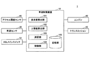
図1は、本発明の一実施例による車速制限装置10を含む車両制御システム1の一例を示す図である。
FIG. 1 is a diagram showing an example of a vehicle control system 1 including a vehicle
車両制御システム1は、車速制限装置10を含む。車速制限装置10は、ECU(Electronic Control Unit)により形成される。
The vehicle control system 1 includes a vehicle
車速制限装置10は、ASL(Adjustable Speed Limiter)機能を備える。
The vehicle speed
車速制限装置10には、車速を検出する車速センサ30と、ASLメインスイッチ32と、アクセル開度(アクセル操作量)を検出するアクセル開度センサ46と、が接続される。車速センサ30は、例えば複数の車輪にそれぞれ設けられる車輪速センサである。この場合、車速は、例えば、複数の車輪速センサの検出値の平均値に基づいて算出される。
A
車速制限装置10は、要求値算出部101と、上限値算出部102と、選択部103と、制御部104と、記憶部105とを含む。
The vehicle
要求値算出部101は、アクセル開度センサ46からのアクセル開度に応じた要求値を算出する。例えば、要求値算出部101は、アクセル開度と、車速とに基づいて、駆動力に関連する要求値を算出する。駆動力に関連する要求値とは、駆動力自体の要求値であってもよいし、加速度、スロットル開度、駆動トルク等に関する要求値であってもよい。以下では、駆動力に関連する要求値は、一例として、駆動力自体の要求値であるとし、「運転者要求駆動力」とも称する。
The required
上限値算出部102は、制限車速に基づいて、駆動力に関連する上限値を算出する。制限車速は、固定値である。或いは、制限車速は、運転者によって設定される設定値である。或いは、制限車速は、ISA(Intelligent Speed Assistance)の場合のように、自動的に設定される。例えば、制限車速は、インフラ等の車外施設(センタサーバーを含む)から通信により取得できる制限速度情報であって、現在の走行中の道路の制限速度を表す制限速度情報に基づいて、自動的に設定される。また、例えば、制限車速は、車載カメラ等を用いて画像認識できる道路標識の制限速度情報に基づいて、自動的に設定される。
The upper
駆動力に関連する上限値とは、駆動力に関連する要求値と同様、駆動力自体の上限値であってもよいし、加速度、スロットル開度、駆動トルク等に関する上限値であってもよい。以下では、駆動力に関連する上限値は、一例として、駆動力自体の上限値であるとし、「上限駆動力」とも称する。上限値算出部102の更なる機能について後述する。
The upper limit value related to the driving force may be the upper limit value of the driving force itself, as well as the required value related to the driving force, or may be the upper limit value related to acceleration, throttle opening, driving torque, and the like. . Hereinafter, the upper limit value related to the driving force is, for example, the upper limit value of the driving force itself, and is also referred to as “upper limit driving force”. Further functions of the upper
選択部103は、要求値算出部101により算出される運転者要求駆動力と、上限値算出部102により算出される上限駆動力のうちの小さい方の値を選択する。例えば、選択部103は、運転者要求駆動力が上限駆動力以上である場合に、上限駆動力を選択し、それ以外の場合は、運転者要求駆動力を選択する。以下、選択部103により選択された駆動力を「目標駆動力」とも称する。また、以下では、選択部103により運転者要求駆動力が選択されている状態を「非制限状態」とも称し、選択部103により上限駆動力が選択されている状態を「制限状態」とも称する。
The
制御部104は、選択部103により選択された駆動力(目標駆動力)に対応した駆動力が発生するようにエンジン40及びトランスミッション42(両者が駆動力発生装置の一例)を制御する。例えば、制御部104は、目標駆動力を発生するように、エンジン40の目標回転数及びトランスミッション42の目標変速比を決定し、目標回転数及び目標変速比が実現されるようにエンジン40及びトランスミッション42を制御する。
The
尚、要求値算出部101、上限値算出部102、選択部103、及び、制御部104は、周期毎に同期して動作する(図3参照)。具体的には、ある周期では、要求値算出部101及び上限値算出部102は、それぞれ、運転者要求駆動力及び上限駆動力を算出し、選択部103は、これらのうちの小さい方の値を選択し、制御部104は、選択された駆動力(目標駆動力)に基づいてエンジン40及びトランスミッション42を制御する。
The required
記憶部105には、要求値算出部101等の各種処理に使用する情報(例えば車両重量、マップ等)が記憶される。
The
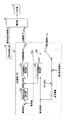
図2は、上限値算出部102の機能ブロック図である。尚、図2には、要求値算出部101、選択部103及び制御部104についても併せて示されている。
FIG. 2 is a functional block diagram of the upper
上限値算出部102には、制限車速、実車速、実加速度、走行抵抗、車両重量、及び、現在発生駆動力が入力される。制限車速は、上述のとおりである。実車速(現在の実車速)は、車速センサ30の出力値に基づく値である。実加速度(現在の実加速度)は、車速センサ30の出力値の微分値に基づく値である。走行抵抗は、例えば実車速に応じて算出される値である。走行抵抗は、転がり抵抗及び空気抵抗を含む。走行抵抗と車速との関係を表すマップは、記憶部105に記憶される。現在発生駆動力は、要求値算出部101により算出される運転者要求駆動力に基づく値である。但し、現在発生駆動力は、現在のエンジン40の出力の推定値(例えば噴射量や空気量から算出値)に基づく値であってもよい。車両重量は、設計値に基づく値であり、記憶部105に記憶される。
The upper limit
上限値算出部102は、これらの入力パラメータ(制限車速、実車速等)に基づいて、上限駆動力を算出し、選択部103に出力する。上限駆動力FLIMITは、図2に示すように、以下の式で算出される。
上限駆動力FLIMIT=FF制限駆動力FFF+制限駆動力FFB 式(1)
制限駆動力FFF(制限値の一例)は、区別のためFF制限駆動力FFFと称する。FF制限駆動力FFFは、次の通り算出される。まず、制限加速度算出部200において、制限車速及び実車速の偏差から制限加速度が算出される。本例では、制限車速及び実車速の偏差は、制限車速から実車速が引かれる。制限加速度は、現在の実車速で許容できる最大の加速度(制限車速の観点から許容できる最大加速度)に対応する。基本的には、制限加速度は、制限車速及び実車速の偏差が大きいほど大きな値が算出される(図6参照)。次いで、FF制限駆動力算出部202において、制限加速度からFF制限駆動力FFFが算出される。FF制限駆動力FFFは、例えば制限加速度に車両重量を乗じた値に、走行抵抗を付加することで算出される。
The upper
Upper limit driving force F LIMIT = FF limit driving force F FF + limit driving force F FB formula (1)
The limiting driving force F FF (an example of a limiting value) is referred to as FF limiting driving force F FF for distinction. The FF limit driving force F FF is calculated as follows. First, the limited
制限駆動力FFB(補正値の一例)は、区別のためFB制限駆動力FFBと称する。FB制限駆動力FFBは、次の2通りの方法のうちの選択された方法で算出される。即ち、FB制限駆動力FFBの算出方法は、2つの方法がある。第1算出方法は、前回周期で選択部103により上限駆動力が選択された場合に、今回周期で用いられる。即ち、第1算出方法は、制限状態で用いられる。第2算出方法は、前回周期で選択部103により運転者要求駆動力が選択された場合に、今回周期で用いられる。即ち、第2算出方法は、非制限状態で用いられる。2つの方法の選択は、図2において符号206が付されたスイッチで模式的に示されている。
Limit drive force F FB (an example of a correction value) is referred to as FB limit drive force F FB for distinction. The FB limited driving force F FB is calculated by a method selected from the following two methods. That is, there are two methods for calculating the FB limit driving force F FB . The first calculation method is used in the current cycle when the upper limit driving force is selected by the
第1算出方法によれば、図2に示すように、FB制限駆動力算出部204において、制限加速度と実加速度の偏差からFB制限駆動力FFBが算出される。例えば、制限加速度から実加速度を引いて得られる加速度偏差に所定のゲインを乗じ、ゲインを乗じて得られた値(今回値)を前回値に積算し(各周期にわたって積分し)、積算して得られた値に、車両重量を乗じることで、FB制限駆動力FFBが算出される。
According to the first calculation method, as shown in FIG. 2, the FB limited driving
第2算出方法によれば、図2に示すように、実加速度と現在発生駆動力とに基づいてFB制限駆動力FFBが算出される。具体的には、図2に示すように、実加速度に車両重量を乗じ、車両重量を乗じて得られた値に、走行抵抗を付加し、付加して得られた値を、現在発生駆動力から引くことで、FB制限駆動力FFBが算出される。即ち、以下のとおりである。
FB制限駆動力FFB=(現在発生駆動力)‐{(車両重量)×(実加速度)+(走行抵抗)} 式(2)
ここで、上記の式(2)の物理的な意味は、車両に作用させる進行方向の力(=現在発生駆動力−走行抵抗)の目標値から、その実際の値の計算値(車両重量×実加速度)を差し引いた値であるので、この差であるFB制限駆動力FFBは、走行中の路面勾配に起因した値となる。具体的には、FB制限駆動力FFBは、現在の走行中の路面勾配が0であるとき(平坦路であるとき)に略0となり、現在の走行中の路面勾配が上り勾配であるときは、正の値となり、現在の走行中の路面勾配が下り勾配であるときは、負の値となる。従って、第2算出方法によれば、走行中の路面勾配が平坦路でない場合であっても、車両に作用させる進行方向の力(=現在発生駆動力−走行抵抗)の目標値が実現されるようなFB制限駆動力FFBを算出できる。
According to the second calculation method, as shown in FIG. 2, the FB limit driving force FFB is calculated based on the actual acceleration and the currently generated driving force. Specifically, as shown in FIG. 2, the actual acceleration is multiplied by the vehicle weight, the running resistance is added to the value obtained by multiplying the vehicle weight, and the value obtained by adding the running resistance is determined as the current generated driving force. By subtracting from FB, the FB limit driving force F FB is calculated. That is, it is as follows.
FB limited driving force F FB = (currently generated driving force) − {(vehicle weight) × (actual acceleration) + (running resistance)} Equation (2)
Here, the physical meaning of the above equation (2) means that the actual value calculated from the target value of the traveling direction force (= currently generated driving force−traveling resistance) applied to the vehicle (vehicle weight × since a value obtained by subtracting the actual acceleration), FB limiting drive force F FB is this difference is a value resulting from the road gradient during travel. Specifically, the FB limited driving force F FB is substantially 0 when the current road surface gradient is 0 (when the road is flat), and the current road surface gradient is an upward gradient. Becomes a positive value, and becomes a negative value when the current road surface gradient is a downward gradient. Therefore, according to the second calculation method, even when the road surface gradient during traveling is not a flat road, the target value of the force in the traveling direction (= currently generated driving force−traveling resistance) applied to the vehicle is realized. Such FB limited driving force F FB can be calculated.
図2に示す構成によれば、FB制限駆動力FFBは、前回周期で選択部103により運転者要求駆動力が選択された場合(非制限状態)と、前回周期で選択部103により上限駆動力が選択された場合(制限状態)とで、異なる方法で算出される。これに伴い、上限駆動力FLIMITは、前回周期で選択部103により運転者要求駆動力が選択された場合と、前回周期で選択部103により上限駆動力が選択された場合とで、異なる方法で算出される。
According to the configuration shown in FIG. 2, the FB limited driving force F FB is the upper limit drive by the selecting
尚、図2に示す例では、上限値算出部102におけるFB制限駆動力FFBを算出するブロック102aが、特許請求の範囲の「上限値補正手段」に対応し、上限値算出部102における他の部分が、特許請求の範囲の「上限値算出手段」に対応する。図2に示す例では、ブロック102aで算出されたFB制限駆動力FFBがFF制限駆動力FFFに加算されることで上限駆動力FLIMITの補正が実現されている。
In the example shown in FIG. 2, the
次に、図3乃至図5のフローチャートを参照して、車速制限装置10の動作について説明する。
Next, the operation of the vehicle
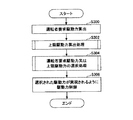
図3は、車速制限装置10により実行される処理の一例を示すフローチャートである。図3に示す処理は、例えば、ASL機能がオンしている間、所定周期毎に実行される。尚、ASL機能は、基本的には、ASLメインスイッチ32がオンしている場合にオンする。
FIG. 3 is a flowchart showing an example of processing executed by the vehicle
ステップS300では、要求値算出部101は、アクセル開度及び車速を読み出し、読み出したアクセル開度及び車速に基づいて、運転者要求駆動力を算出する。
In step S300, the required
ステップS302では、上限値算出部102は、上限駆動力算出処理を行う。上限駆動力算出処理については、図4を参照して後述する。
In step S302, the upper
ステップS304では、選択部103は、ステップS300で得られる運転者要求駆動力と、ステップS302で得られる上限駆動力FLIMITのうちの小さい方の値を選択する選択処理を行う。選択処理については、図5を参照して後述する。
In step S304, the
ステップS306では、制御部104は、ステップS304で選択された駆動力(目標駆動力)に対応した駆動力が発生するようにエンジン40及びトランスミッション42を制御する。
In step S306, the
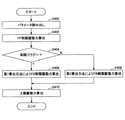
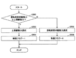
図4は、上限駆動力算出処理の一例を示すフローチャートである。 FIG. 4 is a flowchart illustrating an example of the upper limit driving force calculation process.
ステップS400では、上限値算出部102は、制限車速、実車速、実加速度、走行抵抗、車両重量、及び、現在発生駆動力を読み出す。尚、これらのパラメータのうち、車両重量は固定値であるので、算出式に定数として組み込まれてもよい。
In step S400, the upper
ステップS402では、上限値算出部102は、ステップS400で読み出したパラメータに基づいて、FF制限駆動力FFFを算出する。FF制限駆動力FFFの算出方法は上述のとおりである。
In step S402, the upper limit
ステップS404では、上限値算出部102は、制限フラグが"1"であるか否かを判定する。制限フラグが"0"であることは、非制限状態であることを表し、制限フラグが"1"であることは、制限状態であることを表す。判定結果が"YES"の場合は、ステップS406に進み、判定結果が"NO"の場合は、ステップS408に進む。
In step S404, the
ステップS406では、上限値算出部102は、ステップS400で読み出したパラメータに基づいて、第1算出方法によりFB制限駆動力FFBを算出する。第1算出方法は上述のとおりである。
In step S406, the upper limit
ステップS408では、上限値算出部102は、ステップS400で読み出したパラメータに基づいて、第2算出方法によりFB制限駆動力FFBを算出する。第2算出方法は上述のとおりである。
In step S408, the upper limit
ステップS410では、上限値算出部102は、ステップS402で算出したFF制限駆動力FFFと、ステップS406又はステップS408で算出したFB制限駆動力FFBとに基づいて、上限駆動力FLIMITを算出する。上限駆動力FLIMITの算出方法は上述のとおりである。
In step S410, the upper limit
図4に示す処理によれば、制限フラグが"1"である場合、即ち制限状態である場合に、第1算出方法によりFB制限駆動力FFBを算出し、制限フラグが"0"である場合、即ち非制限状態である場合に、第2算出方法によりFB制限駆動力FFBを算出できる。 According to the processing shown in FIG. 4, when the limit flag is “1”, that is, when the limit flag is in the limit state, the FB limit driving force F FB is calculated by the first calculation method, and the limit flag is “0”. In this case, that is, in the non-restricted state, the FB limited driving force F FB can be calculated by the second calculation method.
図5は、選択処理の一例を示すフローチャートである。 FIG. 5 is a flowchart illustrating an example of the selection process.
ステップS500では、選択部103は、運転者要求駆動力が上限駆動力FLIMIT以上であるか否かを判定する。判定結果が"YES"の場合は、ステップS502に進み、判定結果が"NO"の場合は、ステップS506に進む。
In step S500, the
ステップS502では、選択部103は、上限駆動力FLIMITを選択する。
In step S502, the
ステップS504では、選択部103は、制限フラグを"1"にセットする。
In step S504, the
ステップS506では、選択部103は、運転者要求駆動力を選択する。
In step S506, the
ステップS508では、選択部103は、制限フラグを"0"にセットする。
In step S508, the
図5に示す処理によれば、上限駆動力FLIMITを選択した場合に、制限フラグを"1"にセットし、運転者要求駆動力を選択を選択した場合に、制限フラグを"0"にセットできる。 According to the processing shown in FIG. 5, when the upper limit driving force F LIMIT is selected, the limit flag is set to “1”, and when the driver requested drive force is selected, the limit flag is set to “0”. Can be set.
次に、図6を参照して、FB制限駆動力FFBの第1算出方法の意義について説明する。FB制限駆動力FFBの第1算出方法は、上述の如く、制限状態において採用される。 Next, the significance of the first calculation method for the FB limited driving force F FB will be described with reference to FIG. As described above, the first calculation method of the FB limited driving force F FB is employed in the limited state.
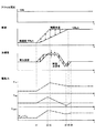
図6は、FB制限駆動力FFBの第1算出方法に基づく上限駆動力FLIMITの算出態様の説明図である。図6には、上から順に、アクセル開度の時系列、車速の時系列、加速度の時系列、及び、各駆動力(FF制限駆動力FFF、FB制限駆動力FFB、上限駆動力FLIMIT)の時系列の一例が示されている。車速の時系列については、実車速の時系列(実線)及び制限車速の時系列(点線)が示されている。また、加速度の時系列については、実加速度の時系列(実線)及び制限加速度の時系列(点線)が示されている。 FIG. 6 is an explanatory diagram of a calculation mode of the upper limit driving force FLIMIT based on the first calculation method of the FB limited driving force FFB . In FIG. 6, in order from the top, the time series of the accelerator opening, the time series of the vehicle speed, the time series of acceleration, and each driving force (FF limiting driving force F FF , FB limiting driving force F FB , upper limit driving force F An example of a time series of LIMIT ) is shown. Regarding the time series of vehicle speed, a time series of actual vehicle speed (solid line) and a time series of limited vehicle speed (dotted line) are shown. As for the time series of acceleration, a time series of actual acceleration (solid line) and a time series of limited acceleration (dotted line) are shown.
図6に示す例では、図6に示す期間中は制限状態が形成されるものとする。時刻t1よりも前は、アクセル開度が100%であり、制限車速が90km/hであり、実車速は略90km/hである。図6に示す例では、時刻t1にて、アクセル開度が100%のままで、制限車速が90km/hから100km/hに変更される。これにより、制限車速が徐々に増加し、時刻t3にて100km/hに達する。これに伴って、制限車速及び実車速の偏差が0よりも有意に大きくなり(図6の上下の矢印参照)、時刻t1よりも前に比べて、制限車速及び実車速の偏差に応じてFF制限駆動力FFFが増加する。 In the example shown in FIG. 6, it is assumed that the restricted state is formed during the period shown in FIG. Prior to time t1, the accelerator opening is 100%, the limited vehicle speed is 90 km / h, and the actual vehicle speed is approximately 90 km / h. In the example shown in FIG. 6, at time t1, the accelerator opening remains 100% and the vehicle speed limit is changed from 90 km / h to 100 km / h. As a result, the vehicle speed limit gradually increases and reaches 100 km / h at time t3. Along with this, the deviation between the limit vehicle speed and the actual vehicle speed becomes significantly larger than 0 (see the up and down arrows in FIG. 6), and the FF according to the deviation between the limit vehicle speed and the actual vehicle speed compared to before time t1. The limiting driving force FFF increases.
また、時刻t1から時刻t2までは制限加速度が実加速度よりも有意に大きく、これに伴い、時刻t1から時刻t2までFB制限駆動力FFBが増加する。他方、時刻t2から時刻t4までは制限加速度が実加速度よりも有意に小さく、これに伴い、時刻t2から時刻t4までFB制限駆動力FFBが減少する。また、時刻t4から時刻t6までは制限加速度が実加速度よりも有意に大きく、これに伴い、時刻t4から時刻t6までFB制限駆動力FFBが増加する。この結果、上限駆動力FLIMITは、図6に示すように、時刻t1から時刻t2まで徐々に増加し、時刻t3の後、時刻t4まで徐々に減少し、その後、時刻t6まで増加する。この結果、時刻t6では、制限車速及び実車速の偏差が略0となる。 Further, the limited acceleration is significantly larger than the actual acceleration from time t1 to time t2, and accordingly, the FB limited driving force FFB increases from time t1 to time t2. On the other hand, the limited acceleration is significantly smaller than the actual acceleration from time t2 to time t4, and accordingly, the FB limited driving force FFB decreases from time t2 to time t4. Further, the limited acceleration is significantly larger than the actual acceleration from time t4 to time t6, and accordingly, the FB limited driving force FFB increases from time t4 to time t6. As a result, as shown in FIG. 6, the upper limit driving force FLIMIT gradually increases from time t1 to time t2, gradually decreases after time t3 until time t4, and then increases until time t6. As a result, at time t6, the deviation between the limited vehicle speed and the actual vehicle speed becomes approximately zero.
このようにして、FB制限駆動力FFBの第1算出方法に基づく上限駆動力FLIMITの算出方法によれば、制限車速及び実車速の偏差が0よりも有意に大きくなった場合に、偏差が0になるように、FF制限駆動力FFF及びFB制限駆動力FFBが算出される。 Thus, according to the calculation method of the upper limit driving force FLIMIT based on the first calculation method of the FB limited driving force FFB , when the deviation between the limited vehicle speed and the actual vehicle speed is significantly larger than 0, the deviation FF limiting driving force F FF and FB limiting driving force F FB are calculated so that becomes zero.
ところで、制限状態において制限車速及び実車速の偏差を0にするために実現すべき駆動力は、制限車速及び実車速の偏差からは一意に決まらず、走行中の路面勾配や車両の積載状態に応じて異なる。従って、制限状態において上限駆動力FLIMIT=FF制限駆動力FFFとする比較構成では、走行中の路面勾配等によっては、制限車速及び実車速の偏差を0にすることが難しくなる。この点、本実施例では、制限状態において上限駆動力FLIMIT=FF制限駆動力FFF+FB制限駆動力FFBとし、FB制限駆動力FFBは、第1算出方法により制限加速度と実加速度の偏差から算出される。走行中の路面勾配等に起因した制御誤差(例えば、制限車速及び実車速の偏差が比較的大きな値に維持される状態)は、制限加速度と実加速度の偏差として現れる。従って、本実施例によれば、走行中の路面勾配等に起因した制御誤差を低減できる。 By the way, the driving force to be realized in order to make the deviation between the restricted vehicle speed and the actual vehicle speed zero in the restricted state is not uniquely determined from the deviation between the restricted vehicle speed and the actual vehicle speed. Depending on. Therefore, in the comparative configuration in which the upper limit driving force F LIMIT = FF the limiting driving force F FF in the limited state, it is difficult to make the deviation between the limited vehicle speed and the actual vehicle speed zero depending on the road surface gradient during traveling. In this respect, in the present embodiment, in the limited state, the upper limit driving force F LIMIT = FF limited driving force F FF + FB limiting driving force F FB , and the FB limiting driving force F FB is calculated by the first calculation method. Calculated from the deviation. A control error (for example, a state in which the deviation between the limited vehicle speed and the actual vehicle speed is maintained at a relatively large value) due to a road surface gradient or the like during traveling appears as a deviation between the limited acceleration and the actual acceleration. Therefore, according to the present embodiment, it is possible to reduce a control error due to a road surface gradient or the like during traveling.
次に、図7及び図8を参照して、FB制限駆動力FFBの第2算出方法の意義について説明する。FB制限駆動力FFBの第2算出方法は、上述の如く、非制限状態において採用される。 Next, the significance of the second calculation method of the FB limit driving force F FB will be described with reference to FIGS. 7 and 8. As described above, the second calculation method of the FB limited driving force F FB is employed in the non-restricted state.
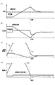
図7は、FB制限駆動力FFBの第2算出方法に基づく上限駆動力FLIMITの算出態様の説明図である。図7には、上から順に、車速の時系列、加速度の時系列、制限駆動力(FF制限駆動力FFF、FB制限駆動力FFB)の時系列、及び、駆動力(運転者要求駆動力及び上限駆動力FLIMIT)の時系列の一例が示されている。車速の時系列については、実車速の時系列(実線)及び制限車速の時系列(点線)が示されている。また、加速度の時系列については、実加速度の時系列(実線)及び制限加速度の時系列(点線)が示されている。また、制限駆動力の時系列については、FF制限駆動力FFFの時系列(実線)及びFB制限駆動力FFBの時系列(点線)が示されている。また、駆動力の時系列については、運転者要求駆動力の時系列(実線)及び上限駆動力FLIMITの時系列(点線)が示されている。図7に示す例では、非制限状態は、時刻t1までの期間、形成され、時刻t1以降は制限状態が形成されている。 FIG. 7 is an explanatory diagram of a calculation mode of the upper limit driving force FLIMIT based on the second calculation method of the FB limited driving force FFB . FIG. 7 shows, in order from the top, a time series of vehicle speed, a time series of acceleration, a time series of limited driving force (FF limited driving force F FF , FB limited driving force F FB ), and driving force (driver requested driving). An example of a time series of force and upper limit driving force FLIMIT ) is shown. Regarding the time series of vehicle speed, a time series of actual vehicle speed (solid line) and a time series of limited vehicle speed (dotted line) are shown. As for the time series of acceleration, a time series of actual acceleration (solid line) and a time series of limited acceleration (dotted line) are shown. As for the time series of the limiting driving force, a time series (solid line) of the FF limiting driving force F FF and a time series (dotted line) of the FB limiting driving force F FB are shown. As for the time series of the driving force, the time series of the driver requested driving force (solid line) and the time series of the upper limit driving force FLIMIT (dotted line) are shown. In the example shown in FIG. 7, the non-restricted state is formed during the period until time t1, and the restricted state is formed after time t1.
図8は、比較例による同時系列を示す図である。比較例では、非制限状態においても、制限状態と同様に、FB制限駆動力FFBが第1算出方法により算出される。図8に示す例では、非制限状態は、時刻t2までの期間、形成され、時刻t2以降は制限状態が形成されている。 FIG. 8 is a diagram illustrating a simultaneous sequence according to a comparative example. In the comparative example, even in the non-restricted state, the FB limited driving force F FB is calculated by the first calculation method as in the limited state. In the example shown in FIG. 8, the non-restricted state is formed during the period up to time t2, and the restricted state is formed after time t2.
ところで、非制限状態においては、上述の如く、車両の駆動力は運転者要求駆動力に基づいて制御されているので、制限加速度と実加速度との加速度偏差が比較的大きくなりやすい。このため、比較例によれば、図8(B)に示すように、制限加速度と実加速度との加速度偏差が比較的大きいことに起因して、図8(C)に示すように、第1算出方法により算出されるFB制限駆動力FFBが大きく増加していく。これに伴い、上限駆動力FLIMITも、図8(D)に示すように、大きく増加していく。この結果、比較例では、図8(A)に示すように、制限車速を実車速が上回っても、非制限状態から制限状態に移行できず、制限車速を実車速が大きく上回った時刻t2にて、非制限状態から制限状態への移行が実現される。これに伴い、図8(D)に示すように、移行直後の駆動力の変動(上限駆動力FLIMITの変動)も比較的大きくなる。このように、比較例によれば、非制限状態から制限状態への移行が遅れ、移行後の駆動力の変動も大きくなる。即ち、非制限状態から制限状態への移行時の円滑性が悪くなる。 By the way, in the non-restricted state, as described above, the driving force of the vehicle is controlled based on the driver-requested driving force, so that the acceleration deviation between the limited acceleration and the actual acceleration tends to be relatively large. For this reason, according to the comparative example, as shown in FIG. 8B, the first deviation as shown in FIG. 8C is caused by the relatively large acceleration deviation between the limited acceleration and the actual acceleration. is calculated by the calculation method FB limiting drive force F FB is gradually increased greatly. Along with this, the upper limit driving force FLIMIT also greatly increases as shown in FIG. As a result, in the comparative example, as shown in FIG. 8A, even when the actual vehicle speed exceeds the limit vehicle speed, the transition from the non-restricted state to the restricted state cannot be made, and at time t2 when the actual vehicle speed greatly exceeds the limit vehicle speed. Thus, the transition from the unrestricted state to the restricted state is realized. Along with this, as shown in FIG. 8D, the driving force fluctuation immediately after the transition (the fluctuation of the upper limit driving force FLIMIT ) also becomes relatively large. Thus, according to the comparative example, the transition from the non-restricted state to the restricted state is delayed, and the fluctuation of the driving force after the transition also increases. That is, the smoothness at the time of transition from the unrestricted state to the restricted state is deteriorated.
これに対して、本実施例によれば、上述の如く、非制限状態においては、第2算出方法によりFB制限駆動力FFBが算出されるので、図7に示すように、非制限状態から制限状態への移行時の円滑性を高めることができる。具体的には、本実施例によれば、第2算出方法によりFB制限駆動力FFBが算出されるので、図7(B)に示すように、制限加速度と実加速度との加速度偏差が比較的大きい場合でも、図7(C)に示すように、第2算出方法により算出されるFB制限駆動力FFBが大きく増加しない。これは、上述の如く、第2算出方法では、制限加速度を用いずに、現在発生駆動力を用いて、FB制限駆動力FFBが算出されるためである。即ち、第2算出方法では、上記の式(2)から分かるように、制限加速度と実加速度との加速度偏差を用いずに、現在発生駆動力に応じた加速度(現在発生駆動力/車両重量)と実加速度との加速度偏差を用いて、FB制限駆動力FFBが算出されるためである。従って、上限駆動力FLIMITは、同様に、制限加速度と実加速度との加速度偏差が比較的大きい場合でも、図7(D)に示すように、大きく増加しない。この結果、本実施例では、図7(A)に示すように、制限車速を実車速が超える前の時刻t1にて、非制限状態から制限状態に移行できる。これに伴い、図7(D)に示すように、移行時の駆動力の変動も比較的小さくできる。このように、本実施例によれば、非制限状態から制限状態への移行時の円滑性を高めることができる。 On the other hand, according to the present embodiment, as described above, in the non-restricted state, the FB limited driving force F FB is calculated by the second calculation method. Therefore, as shown in FIG. Smoothness during the transition to the restricted state can be improved. Specifically, according to the present embodiment, since the FB limited driving force F FB is calculated by the second calculation method, the acceleration deviation between the limited acceleration and the actual acceleration is compared as shown in FIG. Even when the target is large, as shown in FIG. 7C, the FB limit driving force F FB calculated by the second calculation method does not increase greatly. This is because, as described above, in the second calculation method, the FB limited driving force F FB is calculated using the currently generated driving force without using the limited acceleration. That is, in the second calculation method, as can be seen from the above equation (2), the acceleration according to the currently generated driving force (currently generated driving force / vehicle weight) without using the acceleration deviation between the limited acceleration and the actual acceleration. This is because the FB limit driving force F FB is calculated using the acceleration deviation between the actual acceleration and the actual acceleration. Accordingly, the upper limit driving force FLIMIT does not increase greatly as shown in FIG. 7D even when the acceleration deviation between the limited acceleration and the actual acceleration is relatively large. As a result, in the present embodiment, as shown in FIG. 7A, it is possible to shift from the unrestricted state to the restricted state at time t1 before the actual vehicle speed exceeds the restricted vehicle speed. Accordingly, as shown in FIG. 7D, the fluctuation of the driving force at the time of transition can be made relatively small. Thus, according to the present embodiment, the smoothness during the transition from the non-restricted state to the restricted state can be enhanced.
以上、本発明の好ましい実施例について詳説したが、本発明は、上述した実施例に制限されることはなく、本発明の範囲を逸脱することなく、上述した実施例に種々の変形及び置換を加えることができる。 The preferred embodiments of the present invention have been described in detail above. However, the present invention is not limited to the above-described embodiments, and various modifications and substitutions can be made to the above-described embodiments without departing from the scope of the present invention. Can be added.
例えば、上述した実施例では、エンジン40及びトランスミッション42の組み合わせが駆動力発生装置の一例として用いられているが、これに限られない。駆動力発生装置は、電気モータ及びトランスミッションの組み合わせであってもよいし、エンジン、電気モータ及びトランスミッション(例えば遊星歯車による減速機構を含む)の組み合わせであってもよい。
For example, in the above-described embodiment, the combination of the
また、上述した実施例では、上述の如く、一例として、駆動力に関連する要求値は、駆動力自体の要求値(運転者要求駆動力)であり、駆動力に関連する上限値は、駆動力自体の上限値(上限駆動力)である。しかしながら、駆動力に関連する値は、上述の如く、加速度、スロットル開度、駆動トルク等に関する値であってもよい。例えば、駆動力に関連する要求値は、加速度の要求値(運転者要求加速度)であり、駆動力に関連する上限値は、加速度の上限値(上限加速度)であってよい。この場合も、運転者要求駆動力や上限駆動力のような各駆動力は、車両重量で除算されることで、加速度の次元で扱うことができる。例えば、FB制限駆動力FFBは、以下のようにして、FB制限加速度αFBとして算出されてよい。
FB制限加速度αFB=(現在発生駆動力)/(車両重量)‐{(実加速度)+(走行抵抗)/(車両重量)} 式(2')
この場合、式(2')において、(現在発生駆動力)/(車両重量)は、運転者要求加速度に対応する。このようにして得られるFB制限加速度αFBは、FF制限駆動力αFFと足し合せられることで、制限加速度αLIMITが算出される。そして、制限加速度αLIMITは、運転者要求加速度との関係で小さい方の加速度が選択され、選択された加速度が駆動力の次元に変換されてよい。尚、かかる場合も、FB制限加速度αFB(ひいてはそれに基づく制限加速度αLIMIT)が現在発生駆動力等に基づいて算出されていることには変わりはない。
In the above-described embodiment, as described above, for example, the required value related to the driving force is the required value of the driving force itself (driver required driving force), and the upper limit value related to the driving force is the driving force. This is the upper limit value (upper limit driving force) of the force itself. However, the value related to the driving force may be a value related to acceleration, throttle opening, driving torque, and the like as described above. For example, the required value related to the driving force may be a required value of acceleration (driver required acceleration), and the upper limit value related to the driving force may be an upper limit value of acceleration (upper limit acceleration). Also in this case, each driving force such as the driver required driving force and the upper limit driving force can be handled in the dimension of acceleration by being divided by the vehicle weight. For example, the FB limited driving force F FB may be calculated as the FB limited acceleration α FB as follows.
FB limit acceleration α FB = (currently generated driving force) / (vehicle weight) − {(actual acceleration) + (running resistance) / (vehicle weight)} Equation (2 ′)
In this case, in the formula (2 ′), (currently generated driving force) / (vehicle weight) corresponds to the driver required acceleration. The FB limited acceleration α FB obtained in this way is added to the FF limited driving force α FF to calculate the limited acceleration α LIMIT . The limited acceleration α LIMIT may be selected as a smaller acceleration in relation to the driver required acceleration, and the selected acceleration may be converted into a driving force dimension. Even in such a case, the FB limit acceleration α FB (and hence the limit acceleration α LIMIT based on the FB limit acceleration α FB ) is still calculated based on the currently generated driving force and the like.
1 車両制御システム
10 車速制限装置
30 車速センサ
32 ASLメインスイッチ
40 エンジン
42 トランスミッション
46 アクセル開度センサ
101 要求値算出部
102 上限値算出部
103 選択部
104 制御部
105 記憶部
DESCRIPTION OF SYMBOLS 1
Claims (5)
制限車速を取得する制限車速取得手段と、
制限車速及び現在の車速の車速偏差に応じた制限加速度から駆動力に関する上限値を算出する上限値算出手段と、
前記要求値及び前記上限値のうち小さい方の値を選択する選択手段と、
前記選択手段により選択された値に対応した駆動力が発生するように駆動力発生装置を制御する制御手段と、
前記選択手段により前記上限値が選択されている場合は現在の加速度と前記制限加速度から前記上限値を補正し、前記選択手段により前記要求値が選択されている場合は現在の加速度と前記要求値により前記上限値を補正する上限値補正手段と、を含む車速制限装置。 A required value related to the driving force, a required value calculating means for calculating a required value according to the accelerator opening;
Limiting vehicle speed acquisition means for acquiring the limiting vehicle speed;
An upper limit value calculating means for calculating an upper limit value regarding the driving force from the limit acceleration according to the vehicle speed deviation of the limit vehicle speed and the current vehicle speed;
Selecting means for selecting a smaller one of the required value and the upper limit;
Control means for controlling the driving force generator such that the driving force corresponding to the value selected by the selection means is generated;
When the upper limit value is selected by the selection means, the upper limit value is corrected from the current acceleration and the limited acceleration, and when the required value is selected by the selection means, the current acceleration and the required value are corrected. An upper limit correction unit that corrects the upper limit by the vehicle speed limiting device.
前記上限値補正手段は、ある周期で前記選択手段により前記上限値が選択されている場合は次の周期では現在の加速度と前記制限加速度から前記上限値を補正し、ある周期で前記選択手段により前記要求値が選択されている場合は次の周期では現在の加速度と前記要求値により前記上限値を補正する請求項1に記載の車速制限装置。 The required value calculation means, the upper limit value calculation means, the selection means, the control means, and the upper limit value correction means operate in synchronization with each cycle,
The upper limit correction unit corrects the upper limit value from the current acceleration and the limit acceleration in the next cycle when the upper limit value is selected by the selection unit in a certain cycle, and by the selection unit in a certain cycle. The vehicle speed limiting device according to claim 1, wherein when the required value is selected, the upper limit value is corrected by a current acceleration and the required value in a next cycle.
前記上限値補正手段は、ある周期で前記選択手段により前記要求値が選択された場合、次の周期では、走行抵抗と、現在の加速度及び車両重量の積との和を、現在の駆動力から減算することで、前記補正値を算出する、請求項2に記載の車速制限装置。 The upper limit value calculation means, a limit value based on the acceleration limit, by adding the correction value the upper limit value correction means for calculating calculates the upper limit value,
The upper limit value correcting means, when the required value is selected by the selection unit after a certain period in the next cycle, the running resistance, the sum of the acceleration and the vehicle weight of the product of current, the driving of the current The vehicle speed limiting device according to claim 2, wherein the correction value is calculated by subtracting from a force.
Priority Applications (4)
| Application Number | Priority Date | Filing Date | Title |
|---|---|---|---|
| JP2015065174A JP6191644B2 (en) | 2015-03-26 | 2015-03-26 | Vehicle speed limiter |
| US15/070,753 US9714622B2 (en) | 2015-03-26 | 2016-03-15 | Vehicle speed limit apparatus |
| EP16161304.7A EP3072768B1 (en) | 2015-03-26 | 2016-03-21 | Vehicle speed limit apparatus |
| CN201610161821.2A CN106004856B (en) | 2015-03-26 | 2016-03-21 | Speed Limitation Devices |
Applications Claiming Priority (1)
| Application Number | Priority Date | Filing Date | Title |
|---|---|---|---|
| JP2015065174A JP6191644B2 (en) | 2015-03-26 | 2015-03-26 | Vehicle speed limiter |
Publications (2)
| Publication Number | Publication Date |
|---|---|
| JP2016183647A JP2016183647A (en) | 2016-10-20 |
| JP6191644B2 true JP6191644B2 (en) | 2017-09-06 |
Family
ID=55628791
Family Applications (1)
| Application Number | Title | Priority Date | Filing Date |
|---|---|---|---|
| JP2015065174A Active JP6191644B2 (en) | 2015-03-26 | 2015-03-26 | Vehicle speed limiter |
Country Status (4)
| Country | Link |
|---|---|
| US (1) | US9714622B2 (en) |
| EP (1) | EP3072768B1 (en) |
| JP (1) | JP6191644B2 (en) |
| CN (1) | CN106004856B (en) |
Families Citing this family (12)
| Publication number | Priority date | Publication date | Assignee | Title |
|---|---|---|---|---|
| EP2927433B1 (en) * | 2014-04-04 | 2018-09-26 | United Technologies Corporation | Active clearance control for gas turbine engine |
| US11318951B2 (en) * | 2014-10-22 | 2022-05-03 | Transportation Ip Holdings Llc | Vehicle consumption monitoring system and method |
| US12392623B2 (en) | 2014-10-22 | 2025-08-19 | Transportation Ip Holdings, Llc | Vehicle consumption monitoring system and method |
| EP3650294B1 (en) | 2017-07-03 | 2022-03-23 | Nissan Motor Co., Ltd. | Target vehicle speed generation method and target vehicle speed generation device of driving assistance vehicle |
| WO2020026348A1 (en) * | 2018-07-31 | 2020-02-06 | 日産自動車株式会社 | Vehicle control method and control device |
| DE102018213471A1 (en) * | 2018-08-10 | 2020-02-13 | Bayerische Motoren Werke Aktiengesellschaft | Limiting a target value for a control variable of a driver assistance system |
| JP7265345B2 (en) * | 2018-11-19 | 2023-04-26 | 株式会社小松製作所 | WORK VEHICLE, CONTROL DEVICE AND CONTROL METHOD FOR WORK VEHICLE |
| CN111731298B (en) * | 2020-06-30 | 2022-06-03 | 重庆长安汽车股份有限公司 | Speed limit control method and device for new energy automobile and new energy automobile |
| CN112498353B (en) * | 2020-11-30 | 2022-05-10 | 浙江吉利控股集团有限公司 | A method, device, vehicle and medium for preventing abnormal movement of battery pack |
| JP7604944B2 (en) * | 2021-02-26 | 2024-12-24 | トヨタ自動車株式会社 | Vehicle driving force control device |
| JP7586307B2 (en) * | 2021-05-21 | 2024-11-19 | 株式会社デンソー | Processing method, processing system, and processing program |
| CN114919422B (en) * | 2022-05-20 | 2024-08-13 | 合众新能源汽车股份有限公司 | Active speed limiting control method and device for electric automobile and related equipment |
Family Cites Families (15)
| Publication number | Priority date | Publication date | Assignee | Title |
|---|---|---|---|---|
| JP3757674B2 (en) * | 1999-04-12 | 2006-03-22 | 日産自動車株式会社 | Vehicle driving force control device |
| JP4446978B2 (en) * | 2006-04-28 | 2010-04-07 | トヨタ自動車株式会社 | Vehicle driving force control device |
| JP4938542B2 (en) * | 2007-04-27 | 2012-05-23 | トヨタ自動車株式会社 | Vehicle speed control device for vehicle |
| JP4865652B2 (en) * | 2007-08-03 | 2012-02-01 | 本田技研工業株式会社 | Travel speed limit device |
| JP5106171B2 (en) * | 2008-02-21 | 2012-12-26 | 本田技研工業株式会社 | Vehicle travel control device |
| JP5218182B2 (en) * | 2008-08-28 | 2013-06-26 | 日産自動車株式会社 | Vehicle speed limit control device |
| JP5279429B2 (en) * | 2008-09-29 | 2013-09-04 | 株式会社アドヴィックス | Vehicle speed control device |
| WO2010114025A1 (en) * | 2009-03-31 | 2010-10-07 | 本田技研工業株式会社 | Vehicle speed limiter |
| US8219296B1 (en) * | 2011-03-30 | 2012-07-10 | Nissin Kogyo Co., Ltd. | Control device for controlling drive force that operates on vehicle |
| JP6018375B2 (en) | 2011-11-09 | 2016-11-02 | 富士重工業株式会社 | Vehicle travel control device |
| KR101358330B1 (en) * | 2012-09-26 | 2014-02-12 | 현대모비스 주식회사 | Vehicle control speed apparatus, vehicle control speed system comprising the same and method thereof |
| CN104903169B (en) * | 2013-01-11 | 2017-05-31 | 日产自动车株式会社 | The driving-force control apparatus and driving force control method of vehicle |
| JP5892108B2 (en) | 2013-05-13 | 2016-03-23 | トヨタ自動車株式会社 | Vehicle speed control device |
| JP6086107B2 (en) | 2014-10-17 | 2017-03-01 | トヨタ自動車株式会社 | Braking / driving force control device for vehicle |
| JP6137228B2 (en) * | 2015-03-26 | 2017-05-31 | トヨタ自動車株式会社 | Vehicle speed limiter |
-
2015
- 2015-03-26 JP JP2015065174A patent/JP6191644B2/en active Active
-
2016
- 2016-03-15 US US15/070,753 patent/US9714622B2/en active Active
- 2016-03-21 CN CN201610161821.2A patent/CN106004856B/en active Active
- 2016-03-21 EP EP16161304.7A patent/EP3072768B1/en active Active
Also Published As
| Publication number | Publication date |
|---|---|
| US9714622B2 (en) | 2017-07-25 |
| EP3072768B1 (en) | 2018-06-06 |
| EP3072768A2 (en) | 2016-09-28 |
| EP3072768A3 (en) | 2017-04-12 |
| US20160281621A1 (en) | 2016-09-29 |
| CN106004856B (en) | 2018-07-06 |
| CN106004856A (en) | 2016-10-12 |
| JP2016183647A (en) | 2016-10-20 |
Similar Documents
| Publication | Publication Date | Title |
|---|---|---|
| JP6191644B2 (en) | Vehicle speed limiter | |
| JP6137228B2 (en) | Vehicle speed limiter | |
| JP5137764B2 (en) | Vehicle speed control device | |
| JP6379148B2 (en) | Vehicle driving force control device | |
| KR101860192B1 (en) | Driving force control system for vehicle | |
| JP6582484B2 (en) | Travel control device and travel control method | |
| JPWO2018139375A1 (en) | Electric vehicle control method and electric vehicle control apparatus | |
| JP2013233018A (en) | Driving force control device of electric vehicle | |
| JP5316576B2 (en) | Vehicle control device | |
| JP2019199129A (en) | Vehicle travel control device | |
| WO2016152749A1 (en) | Travel control device, and travel control method | |
| JP2014027822A (en) | Vehicle driving force control unit | |
| KR101315726B1 (en) | a distance control system and the method for a car | |
| JP6217723B2 (en) | Driving force control device | |
| JP6229701B2 (en) | Driving force control device | |
| JP2015220912A (en) | Vehicle control device | |
| JP6229702B2 (en) | Driving force control device | |
| JP2006291863A (en) | Vehicle driving force control device | |
| JP2008302726A (en) | VEHICLE CONTROL DEVICE, VEHICLE CONTROL SYSTEM, AND TRAVEL SUPPORT DEVICE | |
| JP2018085900A (en) | Electric vehicle control method and electric vehicle control apparatus | |
| JP2012056377A (en) | Vehicle body vibration damping control device | |
| WO2017159716A1 (en) | Control device for vehicle | |
| JP2016132418A (en) | Control device of vehicle | |
| JP2016017824A (en) | Acceleration correction device | |
| JP2006280099A (en) | Automobile and control method thereof |
Legal Events
| Date | Code | Title | Description |
|---|---|---|---|
| A131 | Notification of reasons for refusal |
Free format text: JAPANESE INTERMEDIATE CODE: A131 Effective date: 20170404 |
|
| A521 | Request for written amendment filed |
Free format text: JAPANESE INTERMEDIATE CODE: A523 Effective date: 20170417 |
|
| TRDD | Decision of grant or rejection written | ||
| A01 | Written decision to grant a patent or to grant a registration (utility model) |
Free format text: JAPANESE INTERMEDIATE CODE: A01 Effective date: 20170711 |
|
| A61 | First payment of annual fees (during grant procedure) |
Free format text: JAPANESE INTERMEDIATE CODE: A61 Effective date: 20170724 |
|
| R151 | Written notification of patent or utility model registration |
Ref document number: 6191644 Country of ref document: JP Free format text: JAPANESE INTERMEDIATE CODE: R151 |