JP2016017824A - Acceleration correction device - Google Patents
Acceleration correction device Download PDFInfo
- Publication number
- JP2016017824A JP2016017824A JP2014140242A JP2014140242A JP2016017824A JP 2016017824 A JP2016017824 A JP 2016017824A JP 2014140242 A JP2014140242 A JP 2014140242A JP 2014140242 A JP2014140242 A JP 2014140242A JP 2016017824 A JP2016017824 A JP 2016017824A
- Authority
- JP
- Japan
- Prior art keywords
- vehicle
- acceleration
- value
- traveling
- correction amount
- Prior art date
- Legal status (The legal status is an assumption and is not a legal conclusion. Google has not performed a legal analysis and makes no representation as to the accuracy of the status listed.)
- Pending
Links
Images
Landscapes
- Control Of Driving Devices And Active Controlling Of Vehicle (AREA)
- Combined Controls Of Internal Combustion Engines (AREA)
Abstract
Description
本発明は、車両の加速度を検出する加速度センサの検出値を補正する加速度補正装置に関する。 The present invention relates to an acceleration correction device that corrects a detection value of an acceleration sensor that detects acceleration of a vehicle.
従来、車両の加速度を検出する加速度センサとして、圧電式及びサーボ式のものなどが知られている。このような加速度センサは、品質のばらつき、経年劣化及び取り付け誤差などによって、その検出値にドリフト誤差が発生する。 2. Description of the Related Art Conventionally, piezoelectric and servo sensors are known as acceleration sensors that detect vehicle acceleration. Such an acceleration sensor causes a drift error in its detection value due to variations in quality, aging deterioration, attachment error, and the like.
このようなドリフト誤差を解消するものとして、例えば、特許文献1では、車速の検出値が所定値以上であり、舵角が中立であり、かつ、スロットル開度が一定に保持されている場合に、車両が定常走行状態にあると判定し、車両が定常走行状態であると判定している期間に、加速度センサの検出値の平均値をドリフト量(ドリフト誤差)として算出し、算出したドリフト量を加速度センサの検出値から差し引くことにより、加速度センサの検出値を補正する装置が提案されている。
In order to eliminate such a drift error, for example, in
また、特許文献2には、車両の左右輪の回転速度差が所定値以下であるときに車両が直進走行していると判定し、車両が直進走行していると判定している期間に横加速度センサから出力される加速度信号の平均値をドリフト量(ドリフト誤差)として算出し、算出したドリフト量を横加速度センサの検出値から差し引くことにより、加速度センサの検出値を補正する装置が提案されている。 Further, in Patent Document 2, it is determined that the vehicle is traveling straight when the difference between the rotational speeds of the left and right wheels of the vehicle is equal to or less than a predetermined value, and the period is determined that the vehicle is traveling straight. A device that corrects the detection value of the acceleration sensor by calculating the average value of the acceleration signal output from the acceleration sensor as a drift amount (drift error) and subtracting the calculated drift amount from the detection value of the lateral acceleration sensor has been proposed. ing.
また、特許文献3及び特許文献4には、前後輪のトルク配分を行うトルク配分クラッチを有する四輪駆動車において、車両の前後方向の路面勾配を推定し、車両の左右輪の回転速度差が所定値以下であるとき、かつ、原動機の出力が所定の範囲内であるときに車両が平坦路直進定速走行状態にあると判定し、車両が平坦路直進定速走行状態であると判定している期間に、前後加速度センサの検出値の平均値をドリフト量(ドリフト誤差)として算出し、算出したドリフト量を前後加速度の検出値から差し引くことにより、加速度センサの検出値を補正する装置がそれぞれ提案されている。
In
しかしながら、特許文献1で提案された装置は、車両が坂道を定常走行している場合には、加速度センサの検出値に対する補正の精度が低下してしまうという課題があった。また、特許文献2で提案された装置は、車両の前後方向の道路勾配による影響を考慮していないため、加速度センサの検出値に対する補正の精度が低下してしまうという課題があった。
However, the apparatus proposed in
また、特許文献3及び特許文献4でそれぞれ提案された装置は、加速度センサの検出値の振動成分などによる加速度センサの検出値のばらつきを考慮していないため加速度センサの検出値に対する補正の精度が低下してしまうという課題があった。
In addition, since the devices proposed in
そこで、本発明は、このような課題を解決するためになされたもので、加速度センサの検出値に対する補正の精度を向上させることができる加速度補正装置を提供することを目的とする。 Therefore, the present invention has been made to solve such a problem, and an object of the present invention is to provide an acceleration correction apparatus that can improve the accuracy of correction of the detection value of the acceleration sensor.
上記課題を解決する本発明に係る加速度補正装置の一態様は、車両の加速度を検出する加速度センサの検出値を補正する加速度補正装置であって、車両が一定の速度で走行しているか否かを判定する定速走行判定部と、車両が走行している走行面が平坦であるか否かを判定する平坦走行判定部と、定速走行判定部によって車両が一定の速度で走行していると判定され、かつ、平坦走行判定部によって車両が走行している走行面が平坦であると判定されたときに、加速度センサの検出値に基づいて、加速度センサの検出値の補正量を算出する補正量算出部と、補正量算出部によって算出された補正量に基づいて、加速度センサの検出値を補正する補正部と、を備え、補正量算出部は、加速度センサの検出値の補正量の標準偏差を算出し、算出した標準偏差が規定値以下であることを条件として、加速度センサの検出値の補正量を更新するように構成されている。 One aspect of the acceleration correction apparatus according to the present invention that solves the above-described problem is an acceleration correction apparatus that corrects a detection value of an acceleration sensor that detects acceleration of a vehicle, and whether or not the vehicle is traveling at a constant speed. The vehicle is traveling at a constant speed by a constant speed traveling determination unit that determines whether the vehicle is traveling, a flat traveling determination unit that determines whether or not the traveling surface on which the vehicle is traveling is flat, and a constant speed traveling determination unit And the correction amount of the detection value of the acceleration sensor is calculated based on the detection value of the acceleration sensor based on the detection value of the acceleration sensor when the flat traveling determination unit determines that the traveling surface on which the vehicle is traveling is flat. A correction amount calculation unit, and a correction unit that corrects the detection value of the acceleration sensor based on the correction amount calculated by the correction amount calculation unit, the correction amount calculation unit of the correction amount of the detection value of the acceleration sensor Calculate the standard deviation On condition that the standard deviation is less than a specified value, and is configured to update the correction amount of the detection value of the acceleration sensor.
このように、本発明は、加速度センサの検出値に対する補正の精度を向上させることができる加速度補正装置を提供することができる。 As described above, the present invention can provide an acceleration correction apparatus that can improve the accuracy of correction with respect to the detection value of the acceleration sensor.
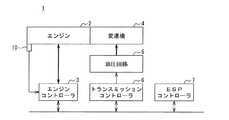
以下、図面を参照して、本発明の実施の形態について詳細に説明する。図1ないし図3に示すように、本発明の実施の形態に係る加速度補正装置を搭載した車両1は、車両1の駆動源としての内燃機関型のエンジン2と、エンジン2を制御するエンジンコントローラ3と、変速機4と、変速機4に形成させる変速段を変更させる油圧回路5と、油圧回路5を介して変速機4を制御するトランスミッションコントローラ6と、車両1の走行状態を制御するESP(Electronic Stability Program)コントローラ7と含んで構成される。
Hereinafter, embodiments of the present invention will be described in detail with reference to the drawings. As shown in FIG. 1 to FIG. 3, a
本実施の形態において、エンジン2は、吸気行程、圧縮行程、膨張行程及び排気行程からなる一連の4行程を行うとともに、圧縮行程及び膨張行程の間に、点火が行われる4サイクルのエンジンによって構成されている。 In the present embodiment, the engine 2 is configured by a four-cycle engine in which a series of four strokes including an intake stroke, a compression stroke, an expansion stroke, and an exhaust stroke is performed, and ignition is performed during the compression stroke and the expansion stroke. Has been.
エンジンコントローラ3は、CPU(Central Processing Unit)と、RAM(Random Access Memory)と、ROM(Read Only Memory)と、フラッシュメモリと、入力ポートと、出力ポートと、ネットワークモジュールとを備えたコンピュータユニットによって構成されている。
The
ネットワークモジュールは、トランスミッションコントローラ6及びESPコントローラ7などの他のコントローラとCAN(Controller Area Network)又はフレックスレイ等の規格に準拠した車内LAN(Local Area Network)を介して通信を行うことができるようになっている。 The network module can communicate with other controllers such as the transmission controller 6 and the ESP controller 7 via an in-vehicle LAN (Local Area Network) conforming to a standard such as CAN (Controller Area Network) or FlexRay. It has become.
エンジンコントローラ3のROMには、各種制御定数や各種マップ等とともに、当該コンピュータユニットをエンジンコントローラ3として機能させるためのプログラムが格納されている。
The ROM of the
すなわち、エンジンコントローラ3において、CPUがROMに格納されたプログラムを実行することにより、当該コンピュータユニットは、エンジンコントローラ3として機能する。
That is, in the
エンジンコントローラ3の入力ポートには、エンジン2の機関回転速度を検出するエンジン回転数センサ10などの各種センサ類が接続されている。また、エンジンコントローラ3の出力ポートには、エンジン2を制御するための各種制御対象類が接続されている。
Various sensors such as an
エンジンコントローラ3は、入力ポートに接続された各種センサ類から得られた情報に基づいて、出力ポートに接続された各種制御対象類を制御するようになっている。例えば、エンジンコントローラ3は、エンジン2に要求した出力と、エンジン回転数センサ10の検出値とに基づいて、エンジン2の出力トルクを検出するトルク検出部30を構成する。
The
また、エンジンコントローラ3は、検出したエンジン2の出力トルクを表す情報をトランスミッションコントローラ6及びESPコントローラ7などの他のコントローラに送信するようになっている。
The
本実施の形態において、変速機4は、トルクコンバータ式オートマチックトランスミッションによって構成され、エンジン2によって生成された動力を変速するようになっている。なお、変速機4は、形成された変速段が電気的に識別できるものであれば、トルクコンバータ式オートマチックトランスミッション以外の変速機によって構成されていてもよい。
In the present embodiment, the
変速機4は、トルクコンバータと、複数の遊星歯車機構と、クラッチ及びブレーキを構成する複数の摩擦係合要素とを有し、トランスミッションコントローラ6によって制御された油圧回路5から供給される作動油に応じて、各摩擦係合要素の掴み変えを行うことにより、所望の変速段を形成するようになっている。
The
トランスミッションコントローラ6は、CPUと、RAMと、ROMと、フラッシュメモリと、入力ポートと、出力ポートと、ネットワークモジュールとを備えたコンピュータユニットによって構成されている。 The transmission controller 6 includes a computer unit that includes a CPU, a RAM, a ROM, a flash memory, an input port, an output port, and a network module.
ネットワークモジュールは、エンジンコントローラ3及びESPコントローラ7などの他のコントローラとCAN又はフレックスレイ等の規格に準拠した車内LANを介して通信を行うことができるようになっている。
The network module can communicate with other controllers such as the
トランスミッションコントローラ6のROMには、各種制御定数や各種マップ等とともに、当該コンピュータユニットをトランスミッションコントローラ6として機能させるためのプログラムが格納されている。 The ROM of the transmission controller 6 stores a program for causing the computer unit to function as the transmission controller 6 along with various control constants and various maps.
すなわち、トランスミッションコントローラ6において、CPUがROMに格納されたプログラムを実行することにより、当該コンピュータユニットは、トランスミッションコントローラ6として機能する。 That is, in the transmission controller 6, the computer unit functions as the transmission controller 6 when the CPU executes a program stored in the ROM.
例えば、トランスミッションコントローラ6は、エンジン2の運転状態及び図示しないシフトポジションセンサの検出値に基づいて、油圧回路5を制御することにより、変速機4に形成させる変速段を変更するようになっている。
For example, the transmission controller 6 changes the gear stage formed in the
また、トランスミッションコントローラ6は、変速機4に形成させる変速段を表す情報をエンジンコントローラ3及びESPコントローラ7などの他のコントローラに送信するようになっている。
In addition, the transmission controller 6 is configured to transmit information indicating the shift speed to be formed in the
ESPコントローラ7は、CPUと、RAMと、ROMと、フラッシュメモリと、入力ポートと、出力ポートと、ネットワークモジュールとを備えたコンピュータユニットによって構成されている。 The ESP controller 7 is configured by a computer unit including a CPU, a RAM, a ROM, a flash memory, an input port, an output port, and a network module.
ネットワークモジュールは、エンジンコントローラ3及びトランスミッションコントローラ6などの他のコントローラとCAN又はフレックスレイ等の規格に準拠した車内LANを介して通信を行うことができるようになっている。
The network module can communicate with other controllers such as the
ESPコントローラ7のROMには、各種制御定数や各種マップ等とともに、当該コンピュータユニットをESPコントローラ7として機能させるためのプログラムが格納されている。 A program for causing the computer unit to function as the ESP controller 7 is stored in the ROM of the ESP controller 7 together with various control constants and various maps.
すなわち、ESPコントローラ7において、CPUがROMに格納されたプログラムを実行することにより、当該コンピュータユニットは、ESPコントローラ7として機能する。 That is, in the ESP controller 7, the computer unit functions as the ESP controller 7 when the CPU executes a program stored in the ROM.
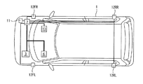
ESPコントローラ7の入力ポートには、車両1の加速度を検出する加速度センサ11と、車両1の速度を検出する車速センサ12と、車両1の舵角を検出する舵角センサ13などの各種センサ類が接続されている。
Various sensors such as an
なお、本実施の形態における車速センサ12は、車両1の右前、左前、右後及び左後にそれぞれ設けられた車輪の回転速度を検出する車輪速センサ12FR、12FL、12RR、12RLによって構成される。
The
ESPコントローラ7の出力ポートには、各種制御対象類が接続されている。ESPコントローラ7は、入力ポートに接続された各種センサ類から得られた情報に基づいて、出力ポートに接続された各種制御対象類を制御するようになっている。 Various control objects are connected to the output port of the ESP controller 7. The ESP controller 7 is configured to control various control objects connected to the output port based on information obtained from various sensors connected to the input port.
本実施の形態において、ESPコントローラ7は、加速度センサ11の検出値を補正する加速度補正装置31を構成する。なお、加速度補正装置31は、エンジンコントローラ3及びトランスミッションコントローラ6などの他のコントローラによって構成されていてもよい。
In the present embodiment, the ESP controller 7 constitutes an
加速度補正装置31は、加速度センサ11の検出値を補正するため、四輪操縦制御、アクティブサスペンション制御、前後トルク配分制御、ニュートラル制御、ヒルホールド制御、誤発進抑制制御及びアイドリングストップ制御などの加速度センサ11の検出値を必要とする各種制御に適用できる。
The
ここで、四輪操縦制御は、車両1の運転状態及び走行環境に応じて各車輪を独立に操縦する制御である。アクティブサスペンション制御は、各車輪に対して設けられたサスペンションの減衰係数を車両1の走行状態に応じて変化させる制御である。前後トルク配分制御は、車両1が四輪駆動車によって構成される場合に、車両1の走行状態に応じて前後輪に伝達するトルクの配分を変化させる制御である。
Here, the four-wheel steering control is control for independently steering each wheel in accordance with the driving state of the
ニュートラル制御は、車両1が停車中に、変速機4に形成させるギヤ段をニュートラルにしてエンジン2にかかる負荷を最小限にする制御である。ヒルホールド制御は、車両1の走行面が進行方向に向けて上昇するように傾斜しているときに、車両1が後方にずり下がらないようにブレーキを作動させる制御である。
The neutral control is a control that minimizes the load applied to the engine 2 by setting the gear stage formed in the
誤発進抑制制御は、アクセルペダルとブレーキペダルの踏み間違えによる急発進を抑制する制御であり、車両1の進行方向に物体がある状況で、アクセルペダルを大きく踏み込んだ場合に、原動機としてのエンジン2の出力を抑制する制御である。アイドリングストップ制御は、エンジン2の出力が必要とされないときに、エンジン2を停止させる制御である。
The erroneous start suppression control is a control that suppresses sudden start due to a mistake in stepping on the accelerator pedal and the brake pedal. When there is an object in the traveling direction of the
上述した、四輪操縦制御、アクティブサスペンション制御、前後トルク配分制御、ニュートラル制御、ヒルホールド制御、誤発進抑制制御、アイドリングストップ制御などの各制御は、各制御の制御対象に応じて、エンジンコントローラ3、トランスミッションコントローラ6及びESPコントローラ7などの各種コントローラによって実行される。
The above-described controls such as four-wheel steering control, active suspension control, longitudinal torque distribution control, neutral control, hill hold control, erroneous start suppression control, idling stop control, and the like are controlled by the
ここで、加速度補正装置31を構成しないコントローラは、加速度補正装置31を構成するコントローラから、補正された加速度を表す信号を車内LANを介して受信するようになっている。すなわち、本実施の形態においては、エンジンコントローラ3及びトランスミッションコントローラ6は、それぞれ必要に応じて、ESPコントローラ7によって補正された加速度を表す信号を受信するようになっている。
Here, the controller that does not constitute the
本実施の形態において、ESPコントローラ7は、車速をより正確に検出するために、駆動輪ではない車輪の車輪速WSl、WSrを用いて以下に示す数式(1)にしたがって車速VSを算出するようになっている。 In the present embodiment, the ESP controller 7 calculates the vehicle speed VS according to the following formula (1) using the wheel speeds WSl and WSr of the wheels that are not drive wheels in order to detect the vehicle speed more accurately. It has become.
VS=(WSl+WSr)×Kwtv (1) VS = (WSl + WSr) × Kwtv (1)
ここで、車輪速WSlは駆動輪ではない左車輪の回転速度とし、車輪速WSrは駆動輪でない右車輪の回転速度とする。例えば、車両1が前輪駆動車によって構成される場合には、車輪速WSlは左後輪の回転速度を表し、車輪速WSrは右後輪の回転速度を表す。また、係数Kwtvは、車輪の径に応じて定められる定数である。
Here, the wheel speed WSl is the rotational speed of the left wheel that is not the driving wheel, and the wheel speed WSr is the rotational speed of the right wheel that is not the driving wheel. For example, when the
なお、車両1が四輪駆動車によって構成される場合には、ESPコントローラ7は、車輪速センサ12FR、12FL、12RR、12RLによって検出した車輪速を平均化し、車輪の径に応じた係数を乗じることにより、車速VSを算出するようにしてもよい。
When the
ESPコントローラ7は、車速センサ12の検出値の変化量が絶対値が第1規定値よりも小さく、かつ、加速度センサ11の検出値の変化量の絶対値が第2規定値よりも小さいことを条件として、車両1が一定の速度で走行していると判定するようになっている。ここで、第1規定値及び第2規定値は、予め実験的にそれぞれ求められた適合値である。
The ESP controller 7 indicates that the change amount of the detection value of the
より詳細には、ESPコントローラ7は、車速センサ12の検出値である車速VSの算出周期がTvsである場合、今回算出された車速VSと前回算出された車速VSbを用いて車速変化量VSdを以下に示す数式(2)にしたがって逐次算出するようになっている。
More specifically, when the calculation cycle of the vehicle speed VS that is a detection value of the
VSd=(VS−VSb)/TvS (2) VSd = (VS−VSb) / TvS (2)
また、ESPコントローラ7は、加速度センサ11の検出値である加速度Giの算出周期がTgである場合、今回算出された加速度Giと前回算出された加速度Gbを用いて加速度変化量Gdを以下に示す数式(3)にしたがって逐次算出するようになっている。
In addition, when the calculation period of the acceleration Gi that is the detection value of the
Gd=(Gi−Gb)/Tg (3) Gd = (Gi−Gb) / Tg (3)
また、ESPコントローラ7は、算出した車速変化量VSdの不要な振動成分を除去するようになっている。一例として、ESPコントローラ7は、車速変化量VSdをなました車速変化量なまし値VSdfを以下に示す数式(4)にしたがって逐次算出するようになっている。なお、数式(4)において、なまし係教をKvsdfとし、前回の車速変化量なまし値をVSdfoとする。また、なまし係教Kvsdfは、0から1までの適合値である。 Further, the ESP controller 7 removes unnecessary vibration components of the calculated vehicle speed change amount VSd. As an example, the ESP controller 7 sequentially calculates the vehicle speed change amount smoothed value VSdf obtained by rounding the vehicle speed change amount VSd according to the following formula (4). In Equation (4), the smoothing teaching is Kvsdf, and the previous vehicle speed change smoothing value is VSdfo. Moreover, the annealing teacher Kvsdf is a fitness value from 0 to 1.
VSdf=Kvsdf×VSdfo+(1−Kvsdf)×VSd (4) VSdf = Kvsdf × VSdfo + (1−Kvsdf) × VSd (4)
また、ESPコントローラ7は、算出した加速度変化量Gdの不要な振動成分を除去するようになっている。一例として、ESPコントローラ7は、加速度変化量Gdをなました加速度変化量なまし値Gdfを以下に示す数式(5)にしたがって逐次算出するようになっている。なお、数式(5)において、なまし係教をKgdfとし、前回の加速度変化量なまし値をGdfoとする。また、なまし係教Kgdfは、0から1までの適合値である。 Further, the ESP controller 7 is configured to remove unnecessary vibration components of the calculated acceleration change amount Gd. As an example, the ESP controller 7 sequentially calculates an acceleration change amount smoothed value Gdf obtained by accelerating the acceleration change amount Gd according to the following equation (5). In Equation (5), the smoothing teaching is Kgdf, and the previous acceleration change smoothing value is Gdfo. Further, the annealing teacher Kgdf is a fitness value from 0 to 1.
Gdf=Kgdf×Gdfo+(1−Kgdf)×Gd (5) Gdf = Kgdf × Gdfo + (1−Kgdf) × Gd (5)
このように算出した車速変化量なまし値VSdf及び加速度変化量なまし値Gdfに基づいて、ESPコントローラ7は、車両1が一定の速度で走行しているか否かを判定する定速走行判定部32を構成する。
Based on the thus calculated vehicle speed change amount smoothing value VSdf and acceleration change amount smoothing value Gdf, the ESP controller 7 determines whether or not the
詳細には、ESPコントローラ7は、車速変化量なまし値VSdfの絶対値が第1規定値よりも小さく、かつ、加速度変化量なまし値Gdfの絶対値が第2規定値よりも小さいことを条件として、車両1が一定の速度で走行していると判定するようになっている。
Specifically, the ESP controller 7 confirms that the absolute value of the vehicle speed change amount smoothing value VSdf is smaller than the first specified value, and that the absolute value of the acceleration change amount smoothing value Gdf is smaller than the second specified value. As a condition, it is determined that the
また、ESPコントローラ7は、算出した車速VSの不要な振動成分を除去するようになっている。一例として、ESPコントローラ7は、車速VSをなました車速なまし値VSfを以下に示す数式(6)にしたがって逐次算出するようになっている。なお、数式(6)において、なまし係教をKvsfとし、前回の車速なまし値をVSfoとする。また、なまし係教Kvsfは、0から1までの適合値である。 Further, the ESP controller 7 is configured to remove unnecessary vibration components of the calculated vehicle speed VS. As an example, the ESP controller 7 sequentially calculates the vehicle speed smoothed value VSf obtained by smoothing the vehicle speed VS according to the following formula (6). In Equation (6), let the smoothing teaching be Kvsf and the previous vehicle speed smoothing value be VSfo. Moreover, the annealing teacher Kvsf is a fitness value from 0 to 1.
VSf=Kvsf×VSfo十(1−Kvsf)×VS (6) VSf = Kvsf × VSfo ten (1−Kvsf) × VS (6)
また、ESPコントローラ7は、エンジンコントローラ3から送信された情報が表す出力トルクTrqの不要な振動成分を除去するようになっている。一例として、ESPコントローラ7は、出力トルクTrqをなました出力トルクなまし値Trqfを以下に示す数式(7)にしたがって逐次算出するようになっている。なお、数式(7)において、なまし係教をKtrqfとし、前回の出力トルクなまし値をTrqoとする。また、なまし係教Ktrqfは、0から1までの適合値である。
Further, the ESP controller 7 is configured to remove an unnecessary vibration component of the output torque Trq represented by the information transmitted from the
Trqf=Ktrqf×Trqo+(1−Ktrqf)×Trq (7) Trqf = Ktrqf × Trqo + (1−Ktrqf) × Trq (7)
本実施の形態において、ESPコントローラ7は、車両1が走行している走行面が平坦であるか否かを判定する平坦走行判定部33を構成する。具体的には、ESPコントローラ7は、車速なまし値VSfと、変速機4が形成する変速段とに応じた規定範囲内に、出力トルクなまし値Trqfがあることを条件として、車両1が走行している走行面が平坦であると判定するようになっている。ここで、変速機4が形成する変速段は、例えば、トランスミッションコントローラ6から送信される。
In the present embodiment, the ESP controller 7 constitutes a flat
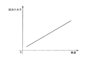
平坦な走行面を走行している車両1におけるエンジン2の出力トルクTrqhの値は車両仕様に寄るものであるが、変速機4に形成された変速段が変更されない限り、一定速度を維持するために必要なエンジン2の出力トルクTrqhは車速が大きくなるほど大きくなるという関係になる。
The value of the output torque Trqh of the engine 2 in the
このため、ESPコントローラ7のROMには、車速と出力トルクTrqhとの関係を表す図4に示すようなトルクマップが変速機4に形成される変速段毎に格納されている。ESPコントローラ7は、トルクマップを参照することにより、車速なまし値VSfと、変速機4が形成する変速段とに応じた規定範囲を特定し、特定した規定範囲内に出力トルクなまし値Trqfがあるか否かを判定するようになっている。
Therefore, a torque map as shown in FIG. 4 representing the relationship between the vehicle speed and the output torque Trqh is stored in the ROM of the ESP controller 7 for each gear stage formed in the
すなわち、ESPコントローラ7は、トルクマップを参照することにより、出力トルクTrqhを特定し、特定した出力トルクTrqhの上下Trqwの範囲を規定範囲として特定し、特定した規定範囲内に出力トルクなまし値Trqfがあるか否かを判定する。なお、Trqwは、車両の運転状態に応じて変化する適合値であってもよく、一定な適合値であってもよい。 That is, the ESP controller 7 specifies the output torque Trqh by referring to the torque map, specifies the range of the upper and lower Trqw of the specified output torque Trqh as the specified range, and outputs the output torque annealing value within the specified specified range. It is determined whether or not there is Trqf. Trqw may be an adaptive value that changes according to the driving state of the vehicle, or may be a constant adaptive value.
詳細には、ESPコントローラ7は、出力トルクTrqhの上下Trqwの範囲内に出力トルクなまし値Trqfがあることを条件として、車両1が平坦な走行面を走行していると判定するようになっている。すなわち、ESPコントローラ7は、以下に示す数式(8)が成立していることを条件として、車両1が平坦な走行面を走行していると判定するようになっている。
Specifically, the ESP controller 7 determines that the
Trqh−Trqw<Trqf<Trqh+Trqw (8) Trqh−Trqw <Trqf <Trqh + Trqw (8)
なお、トルクマップは、変速機4に形成される変速段毎に、車速と、出力トルクTrqhとの関係を表すものであればよく、車速に対する出力トルクTrqhの関係を線形近似した多項式関数でも、テーブルのような非線形関数でもよい。
Note that the torque map only needs to represent the relationship between the vehicle speed and the output torque Trqh for each gear stage formed in the
本実施の形態において、ESPコントローラ7は、舵角センサ13の検出値が所定範囲内にあるか否かを判定するようになっている。ここで、ESPコントローラ7は、舵角センサ13によって検出された舵角SAの不要な振動成分を除去するようになっている。
In the present embodiment, the ESP controller 7 determines whether or not the detected value of the
一例として、ESPコントローラ7は、舵角SAをなました舵角なまし値SAfを以下に示す数式(9)にしたがって逐次算出するようになっている。なお、数式(9)において、なまし係教をKsafとし、前回の舵角なまし値をSAfoとする。また、なまし係教Ksafは、0から1までの適合値である。 As an example, the ESP controller 7 is configured to sequentially calculate the steering angle smoothed value SAf obtained by smoothing the steering angle SA according to the following formula (9). In Equation (9), the smoothing teaching is Ksaf, and the previous steering angle smoothing value is SAfo. Moreover, the annealing teacher Ksaf is a fitness value from 0 to 1.
SAf=KSaf×SAfo+(1−KSaf)×SA (9) SAf = KSaf × SAfo + (1−KSaf) × SA (9)
ESPコントローラ7は、舵角なまし値SAfが所定範囲内にあれば、車両1が直進していると判定し、舵角なまし値SAfが所定範囲内になければ、車両1が直進していないと判定するようになっている。
The ESP controller 7 determines that the
また、ESPコントローラ7は、加速度センサ11の検出値である加速度Giの不要な振動成分を除去するようになっている。一例として、ESPコントローラ7は、加速度Giをなました加速度なまし値Gifを以下に示す数式(10)にしたがって逐次算出するようになっている。なお、数式(10)において、なまし係教をKgfとし、前回の加速度なまし値をGifoとする。また、なまし係教Kgfは、0から1までの適合値である。
Further, the ESP controller 7 is configured to remove unnecessary vibration components of the acceleration Gi that is a detection value of the
Gif=Kgf×Gifo+(1−Kgf)×Gi (10) Gif = Kgf × Gifo + (1−Kgf) × Gi (10)
本実施の形態において、ESPコントローラ7は、車両1が一定の速度で走行していると判定し、車両1が走行している走行面が平坦であると判定し、かつ、車両1が直進していると判定したことを条件に、加速度センサ11の検出値に基づいて、加速度センサ11の検出値の補正量(以下、単に「センサ補正量」ともいう)を算出する補正量算出部34を構成する。
In the present embodiment, the ESP controller 7 determines that the
具体的には、ESPコントローラ7は、車両1が一定の速度で走行していると判定し、車両1が走行している走行面が平坦であると判定し、かつ、車両1が直進していると判定したことを条件に、加速度センサ11の検出値を0にするオフセット値、すなわち、センサ補正量を算出するようになっている。
Specifically, the ESP controller 7 determines that the
詳細には、ESPコントローラ7は、センサ補正量の急激な変動を防止するために、所定サンプル数の加速度センサ補正量を算出したことを条件に、所定サンプル数の加速度なまし値Gifの平均値Gm及び標準偏差Gsを算出するようになっている。ここで、所定サンプル数は、適合値である。 Specifically, the ESP controller 7 calculates the average value of the acceleration smoothed values Gif of a predetermined number of samples on the condition that the acceleration sensor correction amount of a predetermined number of samples is calculated in order to prevent a sudden change in the sensor correction amount. Gm and standard deviation Gs are calculated. Here, the predetermined number of samples is a fitness value.
ESPコントローラ7は、算出した平均値Gm及び標準偏差Gsがそれぞれ規定値以下であることを条件として、センサ補正量を平均値Gmで更新するようになっている。ここで、規定値は、それぞれ適合値である。 The ESP controller 7 is configured to update the sensor correction amount with the average value Gm on condition that the calculated average value Gm and standard deviation Gs are each equal to or less than a specified value. Here, each specified value is a conforming value.
なお、センサ補正量の上限を規制する必要がなければ、ESPコントローラ7は、算出した標準偏差Gsが規定値以下であることを条件として、センサ補正量を平均値Gmで更新するようにしてもよい。 If it is not necessary to regulate the upper limit of the sensor correction amount, the ESP controller 7 may update the sensor correction amount with the average value Gm on condition that the calculated standard deviation Gs is equal to or less than a specified value. Good.
本実施の形態において、ESPコントローラ7は、センサ補正量Gmの不要な振動成分を除去するようになっている。一例として、ESPコントローラ7は、センサ補正量Gmをなましたセンサ補正量なまし値Gerrを以下に示す数式(11)にしたがって逐次算出するようになっている。 In the present embodiment, the ESP controller 7 is configured to remove unnecessary vibration components of the sensor correction amount Gm. As an example, the ESP controller 7 sequentially calculates the sensor correction amount smoothed value Gerr obtained by smoothing the sensor correction amount Gm according to the following formula (11).
なお、数式(11)において、なまし係教をKerrとし、前回のセンサ補正量なまし値をGerroとする。また、なまし係教Kerrは、0から1までの適合値である。また、数式(11)に示すなまし処理は、必ずしも必要ではなく、Gerr=Gmとしてもよい。 In the equation (11), the annealing teaching is Kerr, and the previous sensor correction amount annealing value is Gerro. Moreover, the annealing teacher Kerr is a fitness value from 0 to 1. Further, the annealing process shown in Equation (11) is not necessarily required, and Gerr = Gm may be set.
Gerr=Kerr×Gerro+(1−Kerr)×Gm (11) Gerr = Kerr × Gero + (1−Kerr) × Gm (11)
本実施の形態において、ESPコントローラ7は、算出したセンサ補正量なまし値Gerrに基づいて、加速度センサ11の検出値を補正する補正部35を構成する。すなわち、ESPコントローラ7は、加速度センサ11の検出値Giからセンサ補正量なまし値Gerrを減じることにより、加速度センサ11の検出値を補正し、車両1の加速度Gc(=Gi−Gerr)を算出するようになっている。
In the present embodiment, the ESP controller 7 constitutes a
このように、ESPコントローラ7は、平均値Gm及び標準偏差Gsがそれぞれ規定値以下である場合には、新たに算出したセンサ補正量なまし値Gerrに基づいて、加速度センサ11の検出値を補正し、平均値Gm又は標準偏差Gsがそれぞれ規定値以下でない場合には、既に算出済みのセンサ補正量なまし値Gerrに基づいて、加速度センサ11の検出値を補正するようになっている。
As described above, the ESP controller 7 corrects the detection value of the
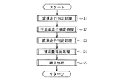
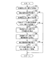
以上のように構成された本発明の実施の形態に係る加速度補正装置の加速度補正動作について図5を参照して説明する。なお、以下に説明する加速度補正動作は、所定の時間間隔で定期的にスタートする。 The acceleration correction operation of the acceleration correction apparatus according to the embodiment of the present invention configured as described above will be described with reference to FIG. In addition, the acceleration correction operation described below starts periodically at predetermined time intervals.
まず、ESPコントローラ7は、車両1が一定速度で走行しているか否かを判定する定速走行判定処理を実行する(ステップS1)。次いで、ESPコントローラ7は、車両1が走行している走行面が平坦であるか否かを判定する平坦面走行判定処理を実行する(ステップS2)。
First, the ESP controller 7 executes a constant speed traveling determination process for determining whether or not the
次いで、ESPコントローラ7は、車両1が直進しているか否かを判定する直進走行判定処理を実行する(ステップS3)。なお、ステップS1ないしステップS3の実行順序は、入れ替えてもよく、2つ以上のステップの少なくとも一部が重複して実行されてもよい。
Next, the ESP controller 7 executes a straight traveling determination process for determining whether or not the
次いで、ESPコントローラ7は、センサ補正量を算出する補正量算出処理を実行する(ステップS4)。このように、算出された補正量に基づいて、ESPコントローラ7は、加速度センサ11の検出値を補正する補正処理を実行する(ステップS5)。 Next, the ESP controller 7 executes a correction amount calculation process for calculating a sensor correction amount (step S4). Thus, based on the calculated correction amount, the ESP controller 7 executes a correction process for correcting the detection value of the acceleration sensor 11 (step S5).
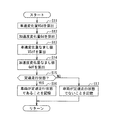
次に、図6を参照して、定速走行判定処理(図5、ステップS1)について詳細に説明する。 Next, the constant speed running determination process (FIG. 5, step S1) will be described in detail with reference to FIG.
まず、ESPコントローラ7は、車速変化量VSdを算出する(ステップS11)。また、ESPコントローラ7は、加速度変化量Gdを算出する(ステップS12)。ここで、ステップS11及びステップS12の実行順序は、入れ替えてもよく、少なくとも一部が重複して実行されてもよい。 First, the ESP controller 7 calculates the vehicle speed change amount VSd (step S11). Further, the ESP controller 7 calculates the acceleration change amount Gd (step S12). Here, the execution order of step S11 and step S12 may be changed, and at least a part may be executed in duplicate.
次いで、ESPコントローラ7は、車速変化量VSdをなました車速変化量なまし値VSdfを算出する(ステップS13)。また、ESPコントローラ7は、加速度変化量Gdをなました加速度変化量なまし値Gdfを算出する(ステップS14)。ここで、ステップS13及びステップS14の実行順序は、入れ替えてもよく、少なくとも一部が重複して実行されてもよい。 Next, the ESP controller 7 calculates a vehicle speed change amount smoothed value VSdf obtained from the vehicle speed change amount VSd (step S13). Further, the ESP controller 7 calculates an acceleration change amount smoothed value Gdf obtained by multiplying the acceleration change amount Gd (step S14). Here, the execution order of step S13 and step S14 may be changed, and at least a part of them may be executed in an overlapping manner.
次いで、ESPコントローラ7は、車両1が一定速度で走行している定速走行状態にあるか否かを判定する(ステップS15)。ここで、ESPコントローラ7は、車速変化量なまし値VSdfの絶対値が第1規定値よりも小さく、かつ、加速度変化量なまし値Gdfの絶対値が第2規定値よりも小さい場合には、車両1が定速走行状態にあると判定し、車速変化量なまし値VSdfの絶対値が第1規定値よりも小さくない、又は、加速度変化量なまし値Gdfの絶対値が第2規定値よりも小さくない場合には、車両1が定速走行状態にないと判定する。
Next, the ESP controller 7 determines whether or not the
ステップS15において、車両1が定速走行状態にあると判定した場合には、ESPコントローラ7は、車両1が定速走行状態にあることを示す情報をRAMなどの記憶媒体に記憶し(ステップS16)、定速走行判定処理を終了する。
If it is determined in step S15 that the
一方、車両1が定速走行状態にないと判定した場合には、ESPコントローラ7は、車両1が定速走行状態にないことを示す情報をRAMなどの記憶媒体に記憶し(ステップS17)、定速走行判定処理を終了する。
On the other hand, when it is determined that the
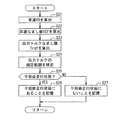
次に、図7を参照して、平坦面走行判定処理(図5、ステップS2)について詳細に説明する。 Next, with reference to FIG. 7, the flat surface travel determination process (FIG. 5, step S2) will be described in detail.
まず、ESPコントローラ7は、車速センサ12の検出値に基づいて、車速VSを算出する(ステップS21)。次いで、ESPコントローラ7は、車速VSをなました車速なまし値VSfを算出する(ステップS22)。 First, the ESP controller 7 calculates the vehicle speed VS based on the detection value of the vehicle speed sensor 12 (step S21). Next, the ESP controller 7 calculates a vehicle speed smoothed value VSf obtained by smoothing the vehicle speed VS (step S22).
次いで、ESPコントローラ7は、エンジン2の出力トルクTrqをなました出力トルクなまし値Trqfを算出する(ステップS23)。次いで、ESPコントローラ7は、トルクマップを参照し、変速機4に形成される変速段と、車速なまし値VSfとに応じた出力トルクの規定範囲を特定する(ステップS24)。
Next, the ESP controller 7 calculates an output torque smoothed value Trqf obtained by smoothing the output torque Trq of the engine 2 (step S23). Next, the ESP controller 7 refers to the torque map and specifies a specified range of output torque according to the shift speed formed in the
次いで、ESPコントローラ7は、車両1が走行している走行面が平坦であるか否か、すなわち、車両1が平坦面走行状態にあるか否かを判定する(ステップS25)。ここで、ESPコントローラ7は、ステップS24で特定した規定範囲内に出力トルクなまし値Trqfがある場合には、車両1が平坦面走行状態にあると判定し、規定範囲内に出力トルクなまし値Trqfがない場合には、車両1が平坦面走行状態にないと判定する。
Next, the ESP controller 7 determines whether or not the traveling surface on which the
ステップS25において、車両1が平坦面走行状態にあると判定した場合には、ESPコントローラ7は、車両1が平坦面走行状態にあることを示す情報をRAMなどの記憶媒体に記憶し(ステップS26)、平坦面走行判定処理を終了する。
If it is determined in step S25 that the
一方、車両1が平坦面走行状態にないと判定した場合には、ESPコントローラ7は、車両1が平坦面走行状態にないことを示す情報をRAMなどの記憶媒体に記憶し(ステップS27)、平坦面走行判定処理を終了する。
On the other hand, when it is determined that the
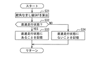
次に、図8を参照して、直進走行判定処理(図5、ステップS3)について詳細に説明する。 Next, with reference to FIG. 8, the straight traveling determination process (FIG. 5, step S3) will be described in detail.
まず、ESPコントローラ7は、舵角SAをなました舵角なまし値SAfを算出する(ステップS31)。次いで、車両1が直進している直進走行状態にあるか否かを判定する(ステップS32)。
First, the ESP controller 7 calculates a steering angle smoothing value SAf obtained by making the steering angle SA (step S31). Next, it is determined whether or not the
ここで、ESPコントローラ7は、舵角なまし値SAfが所定範囲内にあれば、車両1が直進していると判定し、舵角なまし値SAfが所定範囲内になければ、車両1が直進していないと判定する。
Here, the ESP controller 7 determines that the
ステップS32において、車両1が直進走行状態にあると判定した場合には、ESPコントローラ7は、車両1が直進走行状態にあることを示す情報をRAMなどの記憶媒体に記憶し(ステップS33)、直進走行判定処理を終了する。
If it is determined in step S32 that the
一方、車両1が直進走行状態にないと判定した場合には、ESPコントローラ7は、車両1が直進走行状態にないことを示す情報をRAMなどの記憶媒体に記憶し(ステップS34)、直進走行判定処理を終了する。
On the other hand, when it is determined that the
次に、図9を参照して、補正量算出処理(図5、ステップS4)について詳細に説明する。 Next, the correction amount calculation processing (FIG. 5, step S4) will be described in detail with reference to FIG.
まず、ESPコントローラ7は、加速度Giをなました加速度なまし値Gifを算出する(ステップS41)。次いで、ESPコントローラ7は、センサ補正量の算出が許可される補正量算出許可状態にあるか否かを判定する(ステップS42)。 First, the ESP controller 7 calculates an acceleration smoothed value Gif obtained by accelerating the acceleration Gi (step S41). Next, the ESP controller 7 determines whether or not it is in a correction amount calculation permission state in which calculation of the sensor correction amount is permitted (step S42).
ここで、ESPコントローラ7は、車両1が定速走行状態にあること、車両1が平坦面走行状態にあること、及び、車両1が直進走行状態にあることを示す情報がRAMなどの記憶媒体に記憶されている場合には、補正量算出許可状態にあると判定し、車両1が定速走行状態にないこと、車両1が平坦面走行状態にないこと、又は、車両1が直進走行状態にないことを示す情報がRAMなどの記憶媒体に記憶されている場合には、補正量算出許可状態にないと判定する。
Here, the ESP controller 7 stores information indicating that the
ステップS42において、補正量算出許可状態にないと判定した場合には、ESPコントローラ7は、補正量算出処理を終了する。一方、補正量算出許可状態にあると判定した場合には、ESPコントローラ7は、加速度なまし値GifをRAMなどの記憶媒体に記憶する(ステップS43)。 If it is determined in step S42 that the correction amount calculation is not permitted, the ESP controller 7 ends the correction amount calculation process. On the other hand, if it is determined that the correction amount calculation is permitted, the ESP controller 7 stores the acceleration smoothed value Gif in a storage medium such as a RAM (step S43).
次いで、ESPコントローラ7は、所定サンプル数の加速度なまし値Gifを記憶したか否かを判定する(ステップS44)。ここで、所定サンプル数の加速度なまし値Gifを記憶していないと判定した場合には、ESPコントローラ7は、補正量算出処理を終了する。 Next, the ESP controller 7 determines whether or not the acceleration smoothed value Gif of a predetermined number of samples has been stored (step S44). Here, if it is determined that the acceleration smoothed value Gif of the predetermined number of samples is not stored, the ESP controller 7 ends the correction amount calculation process.
一方、所定サンプル数の加速度なまし値Gifを記憶したと判定した場合には、ESPコントローラ7は、加速度なまし値Gifの平均値Gmを算出するとともに(ステップS45)、標準偏差Gsを算出する(ステップS46)。 On the other hand, if it is determined that the acceleration smoothed value Gif of the predetermined number of samples has been stored, the ESP controller 7 calculates the average value Gm of the acceleration smoothed value Gif (step S45) and calculates the standard deviation Gs. (Step S46).
次いで、ESPコントローラ7は、センサ補正量の更新が許可される補正量更新許可状態にあるか否かを判定する(ステップS47)。ここで、ESPコントローラ7は、ステップS45で算出した平均値Gm及びステップS46で算出した標準偏差Gsがそれぞれ規定値以下である場合には、補正量更新許可状態にあると判定し、平均値Gm又は標準偏差Gsがそれぞれ規定値以下でない場合には、補正量更新許可状態にないと判定する。 Next, the ESP controller 7 determines whether or not it is in a correction amount update permission state in which updating of the sensor correction amount is permitted (step S47). Here, when the average value Gm calculated in step S45 and the standard deviation Gs calculated in step S46 are each equal to or less than the specified value, the ESP controller 7 determines that the correction amount update permission state is set, and the average value Gm Alternatively, when the standard deviation Gs is not less than the specified value, it is determined that the correction amount update permission state is not established.
ステップS47において、補正量更新許可状態にあると判定した場合には、ESPコントローラ7は、センサ補正量なまし値Gerrを算出して更新し(ステップS48)、補正量算出処理を終了する。一方、補正量更新許可状態にないと判定した場合には、ESPコントローラ7は、既に算出済みのセンサ補正量なまし値Gerrを維持し、補正量算出処理を終了する。 If it is determined in step S47 that the correction amount update permission state exists, the ESP controller 7 calculates and updates the sensor correction amount smoothing value Gerr (step S48), and ends the correction amount calculation processing. On the other hand, when it is determined that the correction amount update permission state is not set, the ESP controller 7 maintains the already calculated sensor correction amount smoothing value Gerr and ends the correction amount calculation processing.
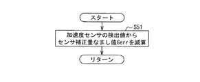
次に、図10を参照して、補正処理(図5、ステップS5)について詳細に説明する。補正処理において、ESPコントローラ7は、加速度センサ11の検出値からセンサ補正量なまし値Gerrを減じることにより、加速度センサ11の検出値を補正する(ステップS51)。
Next, the correction process (FIG. 5, step S5) will be described in detail with reference to FIG. In the correction process, the ESP controller 7 corrects the detection value of the
次に、図11を参照して、本発明の実施の形態に係る加速度補正装置の作用について説明する。 Next, with reference to FIG. 11, the operation of the acceleration correction apparatus according to the embodiment of the present invention will be described.
上述したように、本実施の形態の加速度補正装置は、車両1が定速走行状態にあり、車両1が平坦面走行状態にあり、かつ、車両1が直進走行状態にある期間に、加速度センサ11の検出値のゼロからのオフセットをセンサ補正量として、加速度センサ11の検出値から補正量を減じて補正された加速度を車両1の加速度とする。
As described above, the acceleration correction apparatus according to the present embodiment includes an acceleration sensor during a period in which the
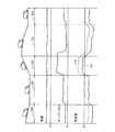
図11には、登坂路、降坂路及び平坦路が連続している環境で、車両1が一定速度で走行している状況が示されている。車両1が一定速度で走行している場合、理想的には進行方向に対する加速度はゼロである。
FIG. 11 shows a situation in which the
そのため、車両1が一定速度で走行している状態では、平坦路101及び104では、加速度センサ11の検出値は、理想的にはゼロとなり、降坂路100及び103並びに登坂路102では、勾配成分により、加速度センサ11の検出値は、車両1の加速度に対して変動する。
Therefore, in a state where the
つまり、加速度センサ11の検出値に誤差がない場合には、加速度センサの検出値は、理想的には破線110で示すようになる。しかし、加速度センサ11の検出値に誤差を含む場合には、例えば、実線111で示すように、誤差分だけオフセットされる。
That is, when there is no error in the detection value of the
したがって、本実施の形態の加速度補正装置は、車両1が定速走行状態にあり、車両1が平坦面走行状態にあり、かつ、車両1が直進走行状態にある期間の加速度センサ11の検出値のゼロからのオフセットを補正量とする。
Therefore, in the acceleration correction device of the present embodiment, the detected value of the
また、車両1が平坦路を一定速度で走行するのに必要なエンジン2の出力は、理想的には車速に対して一意に決まる。また、車両1が一定速度で走行する場合には、登坂路では平坦路に比べてエンジン2の出力は大きく、降坂路では平坦路に比べてエンジン2の出力は小さくなる。
The output of the engine 2 required for the
そこで、本実施の形態の加速度補正装置は、車両1が平坦路を一定速度で走行するのに必要なエンジン2の出力を予め計測しておき、一定速度で走行している期間のエンジン2の出力と、予め計測しておいたエンジン2の出力とを比較することで、これら出力が一致する場合にのみ平坦路を走行していると判定する。
Therefore, the acceleration correction apparatus of the present embodiment measures in advance the output of the engine 2 necessary for the
すなわち、本実施の形態の加速度補正装置は、車両1が一定速度で走行している期間において、車両1が平坦面走行状態にあるときのエンジン2の出力と比較して、エンジン2の出力が大きい場合には、車両1が登坂路を走行していると判定し、エンジン2の出力が小さい場合には、車両1が降坂路を走行していると判定する。
That is, in the acceleration correction device of the present embodiment, the output of the engine 2 is higher than the output of the engine 2 when the
このように、本実施の形態の加速度補正装置は、平坦路を一定速度で走行していると判定した期間に、所定サンプル数の加速度センサ11の検出値の平均値を補正量として、以降に加速度センサ11の検出値から、算出した補正量を差し引くことで加速度信号のゼロからのオフセット量を補正(キャンセル)する。
As described above, the acceleration correction apparatus of the present embodiment uses the average value of the detection values of the
このように、本実施の形態の加速度補正装置は、車両の走行時における不要な振動成分を除去するため、加速度センサ11の検出値のなまし処理を逐次行っている。
As described above, the acceleration correction apparatus according to the present embodiment sequentially performs the process of smoothing the detection value of the
また、本実施の形態の加速度補正装置において、車両1が一定速度で平坦路を走行しているときのなまし後の加速度センサ11の検出値の平均値を補正量とするが、これとともに検出値の標準偏差、すなわち加速度信号のばらつきを算出することで、ばらついた加速度信号から算出された補正量かどうかを監視することもできる。
Further, in the acceleration correction device of the present embodiment, the average value of the detected values of the
さらに、本実施の形態の加速度補正装置は、車両1が走行しているときのエンジン2の出力と、予め計測しておいたエンジン2の出力とを比較することで、車両の前後方向の道路勾配による加速度センサ11の検出値の変動を考慮することができている。
Furthermore, the acceleration correction apparatus according to the present embodiment compares the output of the engine 2 when the
したがって、本実施の形態の加速度補正装置は、なまし処理によって走行時の加速度センサ11の検出値の不要な振動を除去することで間違った加速度情報を使用しないようにしている。
Therefore, the acceleration correction apparatus according to the present embodiment prevents unnecessary acceleration information from being used by removing unnecessary vibration of the detected value of the
すなわち、本実施の形態の加速度補正装置は、ばらつきを監視し、ばらつきが大きい場合には、信用できない情報であるとして、この信用できない情報を補正に使用しないようにしている。 In other words, the acceleration correction apparatus according to the present embodiment monitors variations, and when the variations are large, it is determined that the information is not reliable and is not used for correction.
したがって、本実施の形態の加速度補正装置は、車両前後方向の道路勾配を考慮することで道路勾配による加速度信号のずれを補正量に使用しないようにしているため、より正確でかつ安定した値を算出することができる。 Therefore, the acceleration correction apparatus of the present embodiment does not use the displacement of the acceleration signal due to the road gradient as the correction amount by considering the road gradient in the vehicle longitudinal direction, so that a more accurate and stable value can be obtained. Can be calculated.
このように、本実施の形態の加速度補正装置は、加速度センサ11の検出値のばらつきを監視する機能を有するため、加速度センサ11の検出値のばらつきが小さいときにのみ補正量を算出する。
As described above, since the acceleration correction apparatus according to the present embodiment has a function of monitoring the variation in the detection value of the
つまり、本実施の形態の加速度補正装置は、短期間であっても、加速度センサ11の検出値のばらつきが小さければ安定した信用できる情報であると判定する。なお、本実施の形態の加速度補正装置は、加速度センサ11の検出値のばらつきを監視しているため、ESPコントローラ7が連続して補正量算出許可状態にある必要はなく、補正量算出許可状態にある期間の加速度情報を単純に収集すればよくなるため、補正量を算出するのにかかる時間を短縮している。
That is, the acceleration correction apparatus according to the present embodiment determines that the information is stable and reliable if the variation in the detection value of the
一例として、誤発進抑制制御を実行する車両1に対して本実施の形態の加速度補正装置を適用した場合について説明する。誤発進抑制制御が実行されている期間は、エンジン2の出力を小さく抑えるため、勾配が大きな上り坂では、エンジン2の出力が足らず、車両1が坂を下る方向にずり下がってしまう。このずり下がりを防止するためには、誤発進抑制制御では、道路勾配を監視し道路勾配に応じた制御量で制御をすることが求められる。
As an example, the case where the acceleration correction apparatus of this Embodiment is applied with respect to the
加速度センサ11のような加速度センサは、製品のばらつき、品質のばらつき、経年劣化及び取り付け誤差などによって、その検出値にドリフト誤差が発生し、制御性能が低下することがあるが、本実施の形態の加速度補正装置を適用することにより、誤差の無い道路勾配を検出することができ、上述したずり下がりなどが防止される。
The acceleration sensor such as the
また、本実施の形態の加速度補正装置は、車両仕様に寄らずに適用することができるため、加速度センサ11を構成するセンサや車両1の諸元が変わったとしても、精度よく道路勾配を検出することができる。
In addition, since the acceleration correction apparatus according to the present embodiment can be applied without depending on the vehicle specifications, even if the sensor constituting the
したがって、本実施の形態の加速度補正装置は、あらゆる車種及び仕様の四輪の車両に対して、いかなる道路勾配であっても、ずり下がりを防止した誤発進抑制制御を実現することが可能になる。 Therefore, the acceleration correction apparatus according to the present embodiment can realize erroneous start suppression control that prevents the vehicle from sliding down, regardless of the road gradient, with respect to four-wheeled vehicles of all vehicle types and specifications. .
以上のように、本実施の形態は、車両1が一定の速度で走行していると判定し、かつ、車両1が走行している走行面が平坦であると判定したときに、加速度センサ11の検出値に基づいて、センサ補正量を算出し、センサ補正量の標準偏差を算出し、算出した標準偏差が規定値以下であることを条件として、加速度センサの検出値の補正量を更新する。
As described above, according to the present embodiment, when it is determined that the
したがって、本実施の形態は、加速度センサ11の検出値が理想的にゼロであるときに、加速度センサ11の検出値の補正量を算出し、加速度センサ11の検出値の補正量のばらつきがない場合には、センサ補正量を更新するため、加速度センサ11の検出値に対する補正の精度を向上させることができる。
Therefore, in the present embodiment, when the detection value of the
また、本実施の形態は、車速センサ12の検出値の変化量の絶対値が第1規定値よりも小さく、かつ、加速度センサ11の検出値の変化量の絶対値が第2規定値よりも小さいことを条件として、車両が一定の速度で走行していると判定するため、車両1が一定の速度で走行しているか否かを正確に判定することができる。
In the present embodiment, the absolute value of the change amount of the detection value of the
また、本実施の形態は、車速センサ12の検出値と、変速機4が形成する変速段とに応じた規定範囲内に、エンジン2の出力トルクがあることを条件として、車両1が走行している走行面が平坦であると判定するため、車両1が走行している走行面が平坦であるか否かを正確に判定することができる。
Further, in the present embodiment, the
また、本実施の形態は、舵角センサ13の検出値が所定範囲内にあることを更に条件として、センサ補正量を算出するため、より精度の高い補正量で加速度センサ11の検出値を補正することができる。
Further, in the present embodiment, the sensor correction amount is calculated on the condition that the detection value of the
なお、本実施の形態においては、舵角センサ13の検出値が所定範囲内にあることを更に条件として、センサ補正量を算出するものとして説明したが、センサ補正量を算出する条件から舵角センサ13の検出値が所定範囲内にあることを省いてもよい。
In the present embodiment, the sensor correction amount is calculated on the condition that the detected value of the
この場合には、図5に示した加速度補正動作におけるステップS3は、実行されず、図9に示した補正量算出処理のステップS42において、ESPコントローラ7が補正量算出許可状態にあることの判定条件から車両1が直進走行状態にあることが除かれる。
In this case, step S3 in the acceleration correction operation shown in FIG. 5 is not executed, and it is determined in step S42 of the correction amount calculation process shown in FIG. 9 that the ESP controller 7 is in the correction amount calculation permission state. The condition excludes that the
以上、本発明の実施の形態を開示したが、当業者によっては本発明の範囲を逸脱することなく変更が加えられうることは明白である。すべてのこのような修正及び等価物が特許請求の範囲に記載された請求項に含まれることが意図されている。 Although the embodiments of the present invention have been disclosed above, it is obvious that those skilled in the art can make modifications without departing from the scope of the present invention. All such modifications and equivalents are intended to be included in the claims recited in the claims.
1 車両
4 変速機
11 加速度センサ
12 車速センサ
13 舵角センサ
30 トルク検出部
31 加速度補正装置
32 定速走行判定部
33 平坦走行判定部
34 補正量算出部
35 補正部
DESCRIPTION OF
Claims (4)
前記車両が一定の速度で走行しているか否かを判定する定速走行判定部と、
前記車両が走行している走行面が平坦であるか否かを判定する平坦走行判定部と、
前記定速走行判定部によって前記車両が一定の速度で走行していると判定され、かつ、前記平坦走行判定部によって前記車両が走行している走行面が平坦であると判定されたときに、前記加速度センサの検出値に基づいて、前記加速度センサの検出値の補正量を算出する補正量算出部と、
前記補正量算出部によって算出された補正量に基づいて、前記加速度センサの検出値を補正する補正部と、を備え、
前記補正量算出部は、前記加速度センサの検出値の補正量の標準偏差を算出し、算出した標準偏差が規定値以下であることを条件として、前記加速度センサの検出値の補正量を更新する加速度補正装置。 An acceleration correction device that corrects a detection value of an acceleration sensor that detects acceleration of a vehicle,
A constant speed traveling determination unit that determines whether or not the vehicle is traveling at a constant speed;
A flat travel determination unit for determining whether or not the traveling surface on which the vehicle is traveling is flat;
When it is determined by the constant speed traveling determination unit that the vehicle is traveling at a constant speed, and the flat traveling determination unit determines that the traveling surface on which the vehicle is traveling is flat, A correction amount calculation unit that calculates a correction amount of the detection value of the acceleration sensor based on the detection value of the acceleration sensor;
A correction unit that corrects the detection value of the acceleration sensor based on the correction amount calculated by the correction amount calculation unit;
The correction amount calculation unit calculates a standard deviation of a correction amount of the detection value of the acceleration sensor, and updates the correction amount of the detection value of the acceleration sensor on condition that the calculated standard deviation is equal to or less than a specified value. Acceleration correction device.
前記定速走行判定部は、前記車速センサの検出値の変化量の絶対値が第1規定値よりも小さく、かつ、前記加速度センサの検出値の変化量の絶対値が第2規定値よりも小さいことを条件として、前記車両が一定の速度で走行していると判定する請求項1に記載の加速度補正装置。 A vehicle speed sensor for detecting the speed of the vehicle is provided;
The constant speed travel determination unit has an absolute value of a change amount of the detection value of the vehicle speed sensor smaller than a first specified value, and an absolute value of the change amount of the detection value of the acceleration sensor is smaller than a second specified value. The acceleration correction apparatus according to claim 1, wherein it is determined that the vehicle is traveling at a constant speed on condition that the vehicle is small.
前記駆動源から出力された動力を変速させる変速機と、
前記車両の速度を検出する車速センサと、が設けられ、
前記平坦走行判定部は、前記車速センサの検出値と、前記変速機が形成する変速段とに応じた規定範囲内に、前記トルク検出部の検出値があることを条件として、前記車両が走行している走行面が平坦であると判定する請求項1に記載の加速度補正装置。 A torque detector for detecting an output torque of a driving source of the vehicle;
A transmission for shifting the power output from the drive source;
A vehicle speed sensor for detecting the speed of the vehicle,
The flat travel determination unit is configured to travel the vehicle on the condition that the detection value of the torque detection unit is within a specified range corresponding to a detection value of the vehicle speed sensor and a shift speed formed by the transmission. The acceleration correction apparatus according to claim 1, wherein the running surface is determined to be flat.
前記補正量算出部は、前記舵角センサの検出値が所定範囲内にあることを更に条件として、前記加速度センサの検出値の補正量を算出する請求項1ないし請求項3のいずれか1つの請求項に記載の加速度補正装置。 A steering angle sensor for detecting a steering angle of the vehicle is further provided;
The correction amount calculation unit calculates the correction amount of the detection value of the acceleration sensor on the condition that the detection value of the steering angle sensor is within a predetermined range. The acceleration correction apparatus according to claim.
Priority Applications (1)
| Application Number | Priority Date | Filing Date | Title |
|---|---|---|---|
| JP2014140242A JP2016017824A (en) | 2014-07-08 | 2014-07-08 | Acceleration correction device |
Applications Claiming Priority (1)
| Application Number | Priority Date | Filing Date | Title |
|---|---|---|---|
| JP2014140242A JP2016017824A (en) | 2014-07-08 | 2014-07-08 | Acceleration correction device |
Publications (1)
| Publication Number | Publication Date |
|---|---|
| JP2016017824A true JP2016017824A (en) | 2016-02-01 |
Family
ID=55233139
Family Applications (1)
| Application Number | Title | Priority Date | Filing Date |
|---|---|---|---|
| JP2014140242A Pending JP2016017824A (en) | 2014-07-08 | 2014-07-08 | Acceleration correction device |
Country Status (1)
| Country | Link |
|---|---|
| JP (1) | JP2016017824A (en) |
Cited By (1)
| Publication number | Priority date | Publication date | Assignee | Title |
|---|---|---|---|---|
| KR101936463B1 (en) | 2016-09-05 | 2019-01-08 | 현대자동차주식회사 | Apparatus and method of road slope estimating |
-
2014
- 2014-07-08 JP JP2014140242A patent/JP2016017824A/en active Pending
Cited By (1)
| Publication number | Priority date | Publication date | Assignee | Title |
|---|---|---|---|---|
| KR101936463B1 (en) | 2016-09-05 | 2019-01-08 | 현대자동차주식회사 | Apparatus and method of road slope estimating |
Similar Documents
| Publication | Publication Date | Title |
|---|---|---|
| CN113561791B (en) | Torque redistribution adjustment method and corresponding control unit and electric vehicle | |
| JP6191644B2 (en) | Vehicle speed limiter | |
| JP5152003B2 (en) | Longitudinal acceleration control device | |
| EP3072767B1 (en) | Vehicle speed limit apparatus | |
| JP5967207B2 (en) | Vehicle control apparatus and vehicle control method | |
| CN103459224A (en) | Vehicle driving force control device | |
| JP2011236810A (en) | Driving force control device of vehicle | |
| JP2012210920A (en) | Control device for controlling driving force acting on vehicle | |
| JP2023022556A (en) | Weight estimation device for vehicle | |
| JP2020066315A (en) | Traveling control system | |
| JP6667305B2 (en) | Hydraulic pressure sensor offset correction method and vehicle control device | |
| US20150217772A1 (en) | Vehicle control device and vehicle control method | |
| CN107917188B (en) | Method for controlling shift variation feeling and four-wheel drive vehicle using same | |
| JP2016017824A (en) | Acceleration correction device | |
| JP2018031467A (en) | Vehicle travel control device | |
| JP6747087B2 (en) | Road gradient estimating device and road gradient estimating method | |
| JP4443582B2 (en) | Understeer suppression device | |
| JP5918564B2 (en) | Control device for controlling driving force acting on vehicle | |
| KR102554927B1 (en) | Estimating method of friction coefficient of road surface for vehicle | |
| JP5109855B2 (en) | Gradient estimation device | |
| KR101539403B1 (en) | Apparatus and method to control cvt | |
| KR20220051893A (en) | Dynamic radius of vehicle tire learning method | |
| JP6136870B2 (en) | Vehicle control device | |
| JP2016190604A (en) | Road gradient estimation apparatus and road gradient estimation method | |
| JP2017170928A (en) | Control device for vehicle |