JP5344762B2 - lighting equipment - Google Patents
lighting equipment Download PDFInfo
- Publication number
- JP5344762B2 JP5344762B2 JP2009289564A JP2009289564A JP5344762B2 JP 5344762 B2 JP5344762 B2 JP 5344762B2 JP 2009289564 A JP2009289564 A JP 2009289564A JP 2009289564 A JP2009289564 A JP 2009289564A JP 5344762 B2 JP5344762 B2 JP 5344762B2
- Authority
- JP
- Japan
- Prior art keywords
- time
- lighting
- control
- sunset
- day
- Prior art date
- Legal status (The legal status is an assumption and is not a legal conclusion. Google has not performed a legal analysis and makes no representation as to the accuracy of the status listed.)
- Active
Links
Images




Classifications
-
- Y—GENERAL TAGGING OF NEW TECHNOLOGICAL DEVELOPMENTS; GENERAL TAGGING OF CROSS-SECTIONAL TECHNOLOGIES SPANNING OVER SEVERAL SECTIONS OF THE IPC; TECHNICAL SUBJECTS COVERED BY FORMER USPC CROSS-REFERENCE ART COLLECTIONS [XRACs] AND DIGESTS
- Y02—TECHNOLOGIES OR APPLICATIONS FOR MITIGATION OR ADAPTATION AGAINST CLIMATE CHANGE
- Y02B—CLIMATE CHANGE MITIGATION TECHNOLOGIES RELATED TO BUILDINGS, e.g. HOUSING, HOUSE APPLIANCES OR RELATED END-USER APPLICATIONS
- Y02B20/00—Energy efficient lighting technologies, e.g. halogen lamps or gas discharge lamps
- Y02B20/72—Energy efficient lighting technologies, e.g. halogen lamps or gas discharge lamps in street lighting
Landscapes
- Non-Portable Lighting Devices Or Systems Thereof (AREA)
- Arrangement Of Elements, Cooling, Sealing, Or The Like Of Lighting Devices (AREA)
Abstract
Description
本発明は、蓄電池に蓄えられた太陽電池の発電電力により照明を行う照明器具に関する。 The present invention relates to a luminaire that performs illumination with the generated power of a solar cell stored in a storage battery.
従来の照明器具の一例として、太陽電池を電力供給ユニットに備え、太陽電池が発電した電力によりLED光源を点灯させるようにしたものがある(例えば、特許文献1参照)。 As an example of a conventional lighting fixture, there is one in which a solar battery is provided in a power supply unit, and an LED light source is turned on by power generated by the solar battery (see, for example, Patent Document 1).
上記特許文献1に開示された従来の照明器具では、太陽電池の電圧が蓄電池の電圧より高く、かつ、蓄電池の電圧が上限の設定値以下の場合、太陽電池により蓄電池が充電され、太陽電池の電圧が設定値以下になり、かつ、蓄電池の電圧が下限の設定値以上の場合、照明装置が点灯される。
In the conventional lighting device disclosed in
上記のような従来の照明器具では、街路灯に適用される場合、日の入りに伴い、太陽電池の電圧が設定値以下になり、かつ、蓄電池の電圧が下限の設定値以上の場合に照明装置が点灯されて照明が行われる。そして、所定の照明制御時間の経過後に照明装置の消灯もしくは調光が行われる。しかし、日の入り時刻は季節により変動があるために、照明装置の消灯もしくは調光が行われる時刻が季節により異なるものとなる。図6に示すように、従来の照明器具では、夏季において、時刻t51に日の出があり、時刻t52に日の入りがあった場合、日の入りの時刻t52に照明装置の点灯が開始され、一定の照明制御時間S51の経過後の時刻t53において照明装置の消灯(調光)が行われる。図7に示すように、従来の照明器具では、冬季において、日の出が夏季の時刻t51よりも遅い時刻t54になり、日の入りが夏季の時刻t52よりも早い時刻t55になった場合、日の入りの時刻t55に照明装置の点灯が開始され、一定の照明制御時間S51の経過後の時刻t56において照明装置の消灯(調光)が行われる。即ち、従来の照明器具では、消灯(調光)が行われる夏季の消灯(調光)の時刻t53と冬季の消灯(調光)の時刻t56との間に時間S52の差が生じる。例えば2010年の東京において、照明制御時間S51を6時間00分とした場合、従来の照明器具では、最も遅く点灯が行われる時刻t52になる日が、6月24日から7月4日までの翌日1時1分であり、最も早く点灯が行われる時刻t55になる日が、11月29日から12月13日までの22時28分であり、最も遅い日と最も早い日との間に2時間33分の差が生ずる。
従って、従来の照明器具では、例えば24時(深夜0時)等の予め定められた絶対時刻に消灯(調光)への切換えを行うことができない。
In the conventional lighting apparatus as described above, when applied to a street light, the lighting device is used when the voltage of the solar battery becomes lower than the set value with the sunset and the voltage of the storage battery is higher than the lower limit set value. Illuminated and illuminated. Then, the lighting device is turned off or dimmed after a predetermined lighting control time has elapsed. However, since the sunset time varies depending on the season, the time when the lighting device is turned off or dimmed varies depending on the season. As shown in FIG. 6, in the conventional lighting fixture, when there is sunrise at time t51 and sunset at time t52 in the summer, lighting of the lighting device is started at sunset time t52, and a certain lighting control time is reached. The lighting device is turned off (dimming) at time t53 after the elapse of S51. As shown in FIG. 7, in the conventional lighting apparatus, in the winter season, when the sunrise is a time t54 later than the summer time t51 and the sunset is a time t55 earlier than the summer time t52, the sunset time t55. At this time, the lighting device is turned on, and the lighting device is turned off (dimmed) at time t56 after the elapse of a certain lighting control time S51. That is, in the conventional lighting fixture, a difference in time S52 occurs between the time t53 when the light is turned off (dimming) in summer and the time t56 when light is turned off (dimming) in winter. For example, in Tokyo in 2010, when the lighting control time S51 is set to 6:00 minutes, with the conventional lighting fixture, the time when the latest lighting is performed at time t52 is from June 24 to July 4. The next day is 1:01, and the earliest lighting time at time t55 is 22:28 from November 29 to December 13, between the latest and earliest days. A difference of 2 hours 33 minutes occurs.
Therefore, the conventional lighting fixture cannot be switched off (dimmed) at a predetermined absolute time such as 24:00 (midnight).
上記に対して、所定の時刻で消灯を開始するために、絶対時刻を計時するための時計機能を制御装置に内蔵したり別途に装備したりするようにした照明器具も提案された。しかし、このような従来の照明器具では、時計機能を実現するための集積回路(IC)等を含む追加部品や、初期およびずれの発生時に時計機能を再設定するためのずれ補正機能の部品が必要になってコストの増加をまねく。加えて、時計機能のずれに伴う照明制御時間のずれが生ずる虞がある。 In contrast to the above, there has also been proposed a lighting fixture in which a clock function for measuring the absolute time is incorporated in the control device or separately provided in order to start turning off at a predetermined time. However, in such a conventional lighting fixture, there are additional parts including an integrated circuit (IC) for realizing the clock function, and parts for a deviation correction function for resetting the clock function at the initial time and when a deviation occurs. Necessary to increase the cost. In addition, the illumination control time may be shifted due to the clock function.
本発明は、前述した課題を解決するためになされたものであり、その目的は、その地域におけるその日の日照時間に応じて照明制御時間を自動的に変更することにより一定の時刻での制御をコスト面で有利に行うことができる照明器具を提供することにある。 The present invention has been made to solve the above-described problems, and its purpose is to control at a certain time by automatically changing the lighting control time according to the daylight time of the day in the area. An object of the present invention is to provide a lighting apparatus that can be advantageously performed in terms of cost.
本発明に係る照明器具は、太陽電池と、前記太陽電池により発電した電力を蓄える蓄電池と、前記蓄電池から電力を取り出し点灯する照明装置と、前記蓄電池の充放電および前記照明装置の点灯を制御する制御装置と、前記制御装置に設置地域を設定する手段と、を備え、地域別の日の長さと日の入り時刻との相関データを予め記憶させておき、前記太陽電池の出力状態を検知し、出力が一定値以上となった時から一定値以下となるまでの時間を計測し、その計測時間と前記設置地域とに基づいて、前記照明装置の点灯から消灯もしくは調光となる照明制御時間を可変とする。 A lighting fixture according to the present invention controls a solar battery, a storage battery that stores power generated by the solar battery, a lighting device that takes out power from the storage battery and lights it, and charge / discharge of the storage battery and lighting of the lighting device. A control device, and means for setting an installation area in the control device, storing in advance correlation data between the day length and the sunset time for each region, detecting the output state of the solar cell, and outputting Measures the time from when the value becomes equal to or greater than a certain value until it becomes equal to or less than the certain value, and based on the measurement time and the installation area, the illumination control time from turning on or off or dimming the lighting device is variable And
本発明においては、太陽電池の出力の値により、その日の日照時間が得られ、予め記憶されている地域別の日照時間と日の入り時刻との相関関係により絶対時刻が算出され、算出された絶対時刻に合わせて照明制御時間が可変設定される。
従って、本発明においては、その地域におけるその日の日照時間に応じて照明制御時間が自動的に変更されることにより一定の時刻での制御をコスト面で有利に行うことができる。
In the present invention, the sunshine time of the day is obtained from the value of the output of the solar cell, the absolute time is calculated by the correlation between the sunshine time and the sunset time for each region stored in advance, and the calculated absolute time The illumination control time is variably set according to the above.
Accordingly, in the present invention, the illumination control time is automatically changed according to the daylight hours of the day in the area, so that control at a fixed time can be advantageously performed in terms of cost.
本発明に係る照明器具は、上記照明器具において、前記地域別の日の長さと日の入り時刻との相関データにおいて、同一の日の長さで日の入り時刻が複数存在する場合に、その中間の日の入り時刻を登録する。 In the lighting fixture according to the present invention, in the above-described lighting fixture, in the correlation data between the day length and the sunset time for each region, when there are a plurality of sunset times with the same day length, an intermediate sunset time is provided. Register.
本発明において、日照時間は、例えば夏至から冬至までと、冬至から夏至までとの期間でほぼ反転することになる。そのため、日照時間が同じであっても日の入り時刻は異なるために、双方の日の入り時刻の中間の時刻を相関データとして登録することにより日の入り時刻の誤差を少なくして最適な照明制御時間を設定することができる。 In the present invention, the sunshine hours are substantially reversed during the period from the summer solstice to the winter solstice and from the winter solstice to the summer solstice, for example. Therefore, since the sunset time is different even if the sunshine hours are the same, by registering an intermediate time between the two sunset times as the correlation data, an error in the sunset time can be reduced to set an optimal lighting control time. Can do.
本発明に係る照明器具は、上記照明器具において、前記計測時間を複数日記憶させ、当日以前の前記計測時間との長短の傾向から季節を判定し、参照する相関データを決定する。 The lighting fixture which concerns on this invention WHEREIN: The said lighting time is memorize | stored for several days in the said lighting fixture, a season is judged from the long and short tendency with the said measuring time before the day, and the correlation data to refer are determined.
本発明において、日照時間は、例えば夏至から冬至までと、冬至から夏至までとの期間でほぼ反転することになる。そのため、前日、前々日といった過去の計測時間を記憶しておき、過去の計測時間と当日の計測時間とを比較して長短の傾向からどの季節の変わり目なのかを判定し、いずれの相関データから日の入り時刻を参照するかを決定することにより時期に最適な照明制御時間を誤差なく設定することができる。 In the present invention, the sunshine hours are substantially reversed during the period from the summer solstice to the winter solstice and from the winter solstice to the summer solstice, for example. Therefore, the past measurement time such as the previous day, the day before the previous day is stored, the past measurement time and the measurement time of the day are compared, and it is determined which season changes from the long and short trends, and which correlation data By determining whether or not to refer to the sunset time, the optimal illumination control time can be set without error.
本発明の照明器具によれば、太陽電池の出力の値により、その日の日照時間が得られ、予め記憶されている地域別の日照時間と日の入り時刻との相関関係により絶対時刻が算出され、算出された絶対時刻に合わせて照明制御時間が可変設定される。
これにより、本発明の照明器具によれば、その地域におけるその日の日照時間に応じて照明制御時間が自動的に変更されることにより一定の時刻での制御をコスト面で有利に行うことができる。
According to the lighting fixture of the present invention, the sunshine time of the day is obtained from the output value of the solar cell, and the absolute time is calculated by the correlation between the sunshine time and the sunset time for each region stored in advance. The illumination control time is variably set according to the absolute time.
Thereby, according to the lighting fixture of this invention, the control at a fixed time can be advantageously performed in terms of cost by automatically changing the lighting control time according to the sunshine time of the day in the area. .
以下、本発明の一実施形態に係る照明器具について図面を参照して説明する。
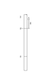
図1に示すように、本発明の一実施形態である照明器具10は、下端部が地面1に埋め込まれる支柱11の上端部に太陽電池12が不図示の太陽に向けて配置されており、太陽電池12の下部に照明装置13が配置されている。そして、支柱の11の下端部寄りに配置されている電源ボックス14内に制御装置15と蓄電池16とが収容されている。
Hereinafter, the lighting fixture which concerns on one Embodiment of this invention is demonstrated with reference to drawings.
As shown in FIG. 1, the
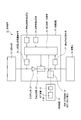
図2に示すように、照明器具10は、太陽電池12と、照明装置13と、制御装置15と、蓄電池16と、を備える。太陽電池12は、例えば、充電用と光センサ(照度センサ)とを兼用した薄膜系の太陽電池12である。薄膜系の太陽電池12は、絶縁基板上にP型、N型、あるいはI型の半導体薄膜による接合が形成され、実用上必要な電圧を得るパターン形成により、基板上でセルが直列接続されたデバイス作成を行う。実用的な薄膜系の太陽電池12はホウケイ酸ガラス基板上に、集電電極と窓材を兼ねるN型CdS薄膜と、P型CdTe薄膜と、裏面電極のC薄膜等とを、順次に印刷と焼結を繰り返し形成する化合物薄膜の太陽電池12である。
As shown in FIG. 2, the
照明装置13は、光源17と、点灯装置18とを備える。光源17がLED(発光ダイオード)である場合、点灯装置18は電池から供給される電力をLED用の直流電源に変換するためのインバータ回路等を内蔵している。点灯装置18は、制御装置15の照明点灯制御部19に接続されている。制御装置15は、太陽電池発電量検知部20と、蓄電池電圧検知部21と、逆流防止部22と、充電制御部23と、照明点灯制御部19と、照明制御時間設定部24と、設置地域設定部25と、演算処理・制御部26と、を備える。蓄電池16は、例えばリチウムイオン電池や鉛蓄電池である。
The
太陽電池発電量検知部20は、太陽電池12が発電した電力の発電量を常時検知しており、検知した発電量(例えば電圧)を演算処理・制御部26に与える。蓄電池電圧検知部21は、蓄電池16に蓄えられた電力を常時検知しており、その電力(例えば電圧)を演算処理・制御部26に与える。逆流防止部22は、蓄電池16から太陽電池12に電流が逆流しないようにするためのダイオードである。充電制御部23は、リレー等のスイッチ回路であって、蓄電池電圧検知部21から得られた蓄電池16の蓄電量が所定の値を超えた際に演算処理・制御部26から与えられる制御信号により駆動されて蓄電池16への電力供給をカットオフする。照明点灯制御部19は、リレー等のスイッチ回路であって、照明制御時間設定部24により設定されている照明制御時間に基づいて演算処理・制御部26から与えられる制御信号により駆動されて点灯装置18の点灯、消灯、調光を切換える。
The solar cell power generation amount detection unit 20 constantly detects the power generation amount of the power generated by the
照明制御時間設定部24は、予め定められた地域の例えば1年間(365日)の日照時間および日の入り時刻を基準時間としてデータテーブルに格納している。設置地域設定部25は、切換えスイッチ等であって、切換えにより照明制御時間設定部24の格納データの中から、設置される地域の日照時間および日の入り時刻が取り出されて、設置される地域の日照時間および日の入り時刻が演算処理・制御部26に転送される。演算処理・制御部26は、演算回路やタイマー回路等を内蔵しており、蓄電池電圧検知部21から与えられた蓄電池16の電力が所定の値を超えて蓄電池16が過充電されないように充電制御部23を駆動させる。演算処理・制御部26は、太陽電池12の発電量が一定値以上となった時点を日の出としてタイマーカウントを開始し、太陽電池12の発電量が一定値以下となった時点を日の入りとしてタイマーカウントを停止して当日の日照時間を設定する。そして、演算処理・制御部26は、予め記憶されている地域別の日照時間と日の入り時刻との相関関係により絶対時刻を算出し、算出した絶対時刻に合わせて照明点灯制御部19を作動させることにより照明制御時間を可変設定する。
なお、データテーブルは、1年間のデータとして365日(毎日)のデータでなくともよく、数日毎のデータでもよい。
The illumination control time setting unit 24 stores the sunshine time and sunset time in a predetermined area, for example, for one year (365 days) as a reference time in the data table. The installation area setting unit 25 is a changeover switch or the like, and the sunshine time and sunset time of the area to be installed are extracted from the stored data of the lighting control time setting unit 24 by switching, and the sunshine of the area to be installed is obtained. The time and sunset time are transferred to the arithmetic processing / control unit 26. The arithmetic processing / control unit 26 incorporates an arithmetic circuit, a timer circuit, etc., and charging control is performed so that the power of the
The data table may not be data for 365 days (daily) as data for one year, but may be data for several days.
図3に示すように、例えば、秋の日Aにおいて、時刻t11に日の出があり、時刻t12に日の入りがあると、その日は時刻t11から時刻t12までの日照時間T11になる。一方、例えば、春の時期の日Bにおいて、秋よりも遅い時刻t13に日の出があり、秋よりも遅い時刻t14に日の入りがあると、その日は時刻t13から時刻t14までが日照時間T12になり、日照時間T11と日照時間T12とは同一の時間になる。しかし、秋の日Aの日の入り時刻t12と春の日Bの日の入り時刻t14とは同一時刻ではなく異なるために、演算処理・制御部26は、秋の日Aの日の入り時刻t12と春の日Bの日の入り時刻t14との中間の時刻t15を相関データとして登録している。 As shown in FIG. 3, for example, in autumn day A, when sunrise occurs at time t11 and sunset occurs at time t12, the day becomes the sunshine time T11 from time t11 to time t12. On the other hand, for example, on day B in the spring season, when there is a sunrise at time t13 later than autumn and sunset occurs at time t14 later than autumn, the day becomes the sunshine time T12 from time t13 to time t14. The time T11 and the sunshine time T12 are the same time. However, since the sunset time t12 of the autumn day A and the sunset time t14 of the spring day B are not the same time, the arithmetic processing / control unit 26 sets the sunset time t12 of the autumn day A and the sunset of the spring day B. A time t15 intermediate to the time t14 is registered as correlation data.
図4に示すように、当日Cにおいて、時刻t15に日の出があり、時刻t16に日の入りがあると、その日は時刻t15から時刻t16までの日照時間T13になる。当日Cの前日の日Dにおいて、時刻t17に日の出があり、時刻t18に日の入りがあると、その日は時刻t17から時刻t18までの日照時間T14になる。当日Cの2日前の日Eにおいて、時刻t19に日の出があり、時刻t20に日の入りがあると、その日は時刻t19から時刻t20までの日照時間T15になる。当日Cの3日前の日Fにおいて、時刻t21に日の出があり、時刻t22に日の入りがあると、その日は時刻t21から時刻t22までの日照時間T16になる。当日Cの4日前の日Gにおいて、時刻t23に日の出があり、時刻t24に日の入りがあると、その日は時刻t23から時刻t24までの日照時間T17になる。このように、4日前の日Gから当日Cまでの比較により、日照時間T17、日照時間T16、日照時間T15、4日照時間T14、日照時間T13と徐々に長くなることに基づいて、演算処理・制御部26は、季節が冬至から夏至に移行する変わり目の時期であると認識して、いずれの相関データから日の入り時刻を参照するかを決定する。 As shown in FIG. 4, on the day C, when sunrise occurs at time t15 and sunset occurs at time t16, the day becomes the sunshine time T13 from time t15 to time t16. On the day D of the day before the current day C, when sunrise occurs at time t17 and sunset occurs at time t18, the day becomes the sunshine time T14 from time t17 to time t18. If there is a sunrise at time t19 on the day E two days before the current day C and there is a sunset at time t20, the day will be the sunshine time T15 from time t19 to time t20. On the day F three days before the day C, if there is a sunrise at time t21 and there is a sunset at time t22, the day will be the sunshine time T16 from time t21 to time t22. On the day G four days before the day C, if there is a sunrise at time t23 and there is a sunset at time t24, the day will be the sunshine time T17 from time t23 to time t24. As described above, based on the comparison from the day G to the day C 4 days ago, the calculation process is performed on the basis of the sunshine time T17, the sunshine time T16, the sunshine time T15, the sunshine time T14, and the sunshine time T13. The control unit 26 recognizes that the season is a turning point when the season changes from the winter solstice to the summer solstice, and determines which correlation data is used to refer to the sunset time.
次に、照明器具10の制御動作について説明する。図5に示すように、制御が開始され、太陽電池12の発電量が一定値以上となっていないと、日の出ではないと認識されて待機状態となり、太陽電池12の発電量が一定値以上となると、その時点を日の出と認識してタイマーカウントが開始される(S101)。日の出が認識された後に、太陽電池12の発電量が一定値以下となっていないと、日の入りではないと認識されて待機状態となり、太陽電池12の発電量が一定値以下となると、その時点を日の入りと認識してタイマーカウントが停止される(S101→S102)。日の入りが認識されたことにより、演算処理・制御部26からの制御信号により照明点灯制御部19が駆動されて照明装置13の光源17が点灯される(S102→S103)。
Next, the control operation of the
このとき、演算処理・制御部26には、設置地域設定部25により切換えられた地域の日照時間および日の入り時刻が選択設定されており、演算処理・制御部26は、照明制御時間設定部24により設定されている地域の1年間(365日)の日照時間および日の入り時刻の基準時間とその日の日照時間(計測時間)との差を算出(S103→S104)し、当日の日照時間に対応する日の入り時刻を選び出し、選び出された日の入り時刻から消灯(調光)に切換えるまでの照明制御時間を算出設定する(S105→S106)。消灯(調光)に切換える時刻に到達するまでは照明点灯制御部19により点灯が継続して行われ、消灯時刻に到達したときに照明点灯制御部19により点灯が消灯(調光)に切換えられる(S107→S108)。 At this time, the sunshine hours and sunset times of the areas switched by the installation area setting unit 25 are selected and set in the calculation processing / control unit 26, and the calculation processing / control unit 26 is set by the illumination control time setting unit 24. Calculate the difference between the standard time of daylight time and sunset time of the set area for one year (365 days) and the daylight time (measurement time) of the day (S103 → S104), and set the daylight corresponding to the daylight time of the day The time is selected, and the illumination control time from when the selected sunset time is switched to turning off (dimming) is calculated and set (S105 → S106). The lighting is continuously turned on by the illumination lighting control unit 19 until the time for switching to off (dimming) is reached, and when the lighting time is reached, the lighting on / off control unit 19 switches on lighting to off (dimming). (S107 → S108).
なお、照明器具10では、照明制御時間の経過後に消灯に切換えているが、これとは異なり、照明制御時間の経過後に調光状態として一定時間経過後もしくは日の出の検知後に消灯することもできる。さらに、照明制御時間内においても調光点灯を行うことにより消費電力を抑制することもできる。
In addition, in the
本発明の一実施形態の照明器具10では、太陽電池12の出力の値により、その日の日照時間が得られ、予め記憶されている地域別の日照時間と日の入り時刻との相関関係により絶対時刻が算出され、算出された絶対時刻に合わせて照明制御時間が可変設定される。
従って、本発明の一実施形態の照明器具10では、その地域におけるその日の日照時間に応じて照明制御時間が自動的に変更されることにより一定の時刻での制御をコスト面で有利に行うことができる。
In the
Therefore, in the
本発明の一実施形態の照明器具10では、日照時間は、例えば夏至から冬至までと、冬至から夏至までとの期間でほぼ反転することになる。そのため、日照時間が同じであっても日の入り時刻は異なるために、双方の日の入り時刻の中間の時刻を相関データとして登録することにより日の入り時刻の誤差を少なくして最適な照明制御時間を設定することができる。
In the
本発明の一実施形態の照明器具10では、日照時間は、例えば夏至から冬至までと、冬至から夏至までとの期間でほぼ反転することになる。そのため、前日、前々日といった過去の計測時間を記憶しておき、過去の計測時間と当日の計測時間とを比較して長短の傾向からどの季節の変わり目なのかを判定し、いずれの相関データから日の入り時刻を参照するかを決定することにより時期に最適な照明制御時間を誤差なく設定することができる。
In the
なお、前記一実施形態で使用した支柱11、太陽電池12、照明装置13、蓄電池16等は例示したものに限定するものではなく適宜変更が可能である。
In addition, the support |
10 照明器具
12 太陽電池
13 照明装置
15 制御装置
16 蓄電池
25 設置地域設定部(設置地域を設定する手段)
DESCRIPTION OF
Claims (3)
前記太陽電池により発電した電力を蓄える蓄電池と、
前記蓄電池から電力を取り出し点灯する照明装置と、
前記蓄電池の充放電および前記照明装置の点灯を制御する制御装置と、
前記制御装置に設置地域を設定する手段と、
を備え、
地域別の日の長さと日の入り時刻との相関データを予め記憶させておき、前記太陽電池の出力状態を検知し、出力が一定値以上となった時から一定値以下となるまでの時間を計測し、その計測時間と前記設置地域とに基づいて、前記照明装置の点灯から消灯もしくは調光となる照明制御時間を可変とする照明器具。 Solar cells,
A storage battery for storing electric power generated by the solar battery;
A lighting device that takes out power from the storage battery and lights it;
A control device for controlling charging / discharging of the storage battery and lighting of the lighting device;
Means for setting an installation area in the control device;
With
Correlation data between day length and sunset time for each region is stored in advance, the output state of the solar cell is detected, and the time from when the output exceeds a certain value to when it falls below a certain value is measured Then, based on the measurement time and the installation area, a lighting fixture in which the lighting control time during which the lighting device is turned on or off or dimmed is variable.
Priority Applications (1)
| Application Number | Priority Date | Filing Date | Title |
|---|---|---|---|
| JP2009289564A JP5344762B2 (en) | 2009-12-21 | 2009-12-21 | lighting equipment |
Applications Claiming Priority (1)
| Application Number | Priority Date | Filing Date | Title |
|---|---|---|---|
| JP2009289564A JP5344762B2 (en) | 2009-12-21 | 2009-12-21 | lighting equipment |
Publications (2)
| Publication Number | Publication Date |
|---|---|
| JP2011129472A JP2011129472A (en) | 2011-06-30 |
| JP5344762B2 true JP5344762B2 (en) | 2013-11-20 |
Family
ID=44291834
Family Applications (1)
| Application Number | Title | Priority Date | Filing Date |
|---|---|---|---|
| JP2009289564A Active JP5344762B2 (en) | 2009-12-21 | 2009-12-21 | lighting equipment |
Country Status (1)
| Country | Link |
|---|---|
| JP (1) | JP5344762B2 (en) |
Families Citing this family (1)
| Publication number | Priority date | Publication date | Assignee | Title |
|---|---|---|---|---|
| CN111246618A (en) * | 2020-03-12 | 2020-06-05 | 江西五和电气有限公司 | Photovoltaic LED lighting product capable of changing color temperature according to seasons |
Family Cites Families (3)
| Publication number | Priority date | Publication date | Assignee | Title |
|---|---|---|---|---|
| JP2001143876A (en) * | 1999-11-18 | 2001-05-25 | Matsushita Electric Works Ltd | Lighting device |
| JP4081326B2 (en) * | 2002-08-28 | 2008-04-23 | 日本街路灯製造株式会社 | Street light |
| JP2007174142A (en) * | 2005-12-21 | 2007-07-05 | Kowa Co | Video distribution system |
-
2009
- 2009-12-21 JP JP2009289564A patent/JP5344762B2/en active Active
Also Published As
| Publication number | Publication date |
|---|---|
| JP2011129472A (en) | 2011-06-30 |
Similar Documents
| Publication | Publication Date | Title |
|---|---|---|
| US9693433B2 (en) | Apparatus and method for schedule based operation of a luminaire | |
| JP2012094273A (en) | Lighting system | |
| JP5849210B2 (en) | Lighting device with solar power generation function | |
| CA3044482C (en) | Led lighting system and a method therefor | |
| JP2012084441A (en) | Lighting system | |
| KR20140147226A (en) | Led street light apparatus realizing color temperature/iintensity of illumination according to real-time weather conditions | |
| JP2010212232A (en) | Lighting system and lighting control method | |
| JP5344762B2 (en) | lighting equipment | |
| JP5495371B2 (en) | lighting equipment | |
| KR101900458B1 (en) | Solar LED lighting device turned on/off depending on sunrise/sunset time using latitude/longitude and time information | |
| KR20080082047A (en) | Road lighting device using solar cell | |
| JP2011034939A (en) | Illumination device for nighttime | |
| CN101442216B (en) | Power Switching Device for Auxiliary Natural Energy Power Supply | |
| KR100943749B1 (en) | Solar power street light | |
| CN201902964U (en) | Solar street lamp | |
| KR200386062Y1 (en) | LED Lighting Apparatus with Photovoltaic Generating system | |
| JP5849209B2 (en) | Lighting device with solar power generation function | |
| KR20100068707A (en) | Lighting apparatus using transparent solar cell | |
| CN202993002U (en) | Solar light-emitting-diode (LED) road lamp | |
| KR101267974B1 (en) | Lighting device using solar cell | |
| KR200249885Y1 (en) | A outdoor advertising apparatus using electronic luminance sheet | |
| Pachamanov et al. | Management of street lighting by relative value of the rate of change of natural light | |
| CN201902959U (en) | LED (light-emitting diode) street lamp with transparent film solar panels | |
| KR20130071315A (en) | Light device using solar enenrgy | |
| KR950003077Y1 (en) | Power supply apparatus by solar energy |
Legal Events
| Date | Code | Title | Description |
|---|---|---|---|
| A711 | Notification of change in applicant |
Free format text: JAPANESE INTERMEDIATE CODE: A712 Effective date: 20120116 |
|
| A621 | Written request for application examination |
Free format text: JAPANESE INTERMEDIATE CODE: A621 Effective date: 20120712 |
|
| A977 | Report on retrieval |
Free format text: JAPANESE INTERMEDIATE CODE: A971007 Effective date: 20130711 |
|
| TRDD | Decision of grant or rejection written | ||
| A01 | Written decision to grant a patent or to grant a registration (utility model) |
Free format text: JAPANESE INTERMEDIATE CODE: A01 Effective date: 20130716 |
|
| A61 | First payment of annual fees (during grant procedure) |
Free format text: JAPANESE INTERMEDIATE CODE: A61 Effective date: 20130812 |
|
| R150 | Certificate of patent or registration of utility model |
Ref document number: 5344762 Country of ref document: JP Free format text: JAPANESE INTERMEDIATE CODE: R150 Free format text: JAPANESE INTERMEDIATE CODE: R150 |