JP2012084441A - Lighting system - Google Patents
Lighting system Download PDFInfo
- Publication number
- JP2012084441A JP2012084441A JP2010230875A JP2010230875A JP2012084441A JP 2012084441 A JP2012084441 A JP 2012084441A JP 2010230875 A JP2010230875 A JP 2010230875A JP 2010230875 A JP2010230875 A JP 2010230875A JP 2012084441 A JP2012084441 A JP 2012084441A
- Authority
- JP
- Japan
- Prior art keywords
- season
- determination unit
- person
- unit
- light source
- Prior art date
- Legal status (The legal status is an assumption and is not a legal conclusion. Google has not performed a legal analysis and makes no representation as to the accuracy of the status listed.)
- Pending
Links
Images





Classifications
-
- F—MECHANICAL ENGINEERING; LIGHTING; HEATING; WEAPONS; BLASTING
- F21—LIGHTING
- F21S—NON-PORTABLE LIGHTING DEVICES; SYSTEMS THEREOF; VEHICLE LIGHTING DEVICES SPECIALLY ADAPTED FOR VEHICLE EXTERIORS
- F21S9/00—Lighting devices with a built-in power supply; Systems employing lighting devices with a built-in power supply
- F21S9/02—Lighting devices with a built-in power supply; Systems employing lighting devices with a built-in power supply the power supply being a battery or accumulator
- F21S9/03—Lighting devices with a built-in power supply; Systems employing lighting devices with a built-in power supply the power supply being a battery or accumulator rechargeable by exposure to light
- F21S9/032—Lighting devices with a built-in power supply; Systems employing lighting devices with a built-in power supply the power supply being a battery or accumulator rechargeable by exposure to light the solar unit being separate from the lighting unit
-
- F—MECHANICAL ENGINEERING; LIGHTING; HEATING; WEAPONS; BLASTING
- F21—LIGHTING
- F21S—NON-PORTABLE LIGHTING DEVICES; SYSTEMS THEREOF; VEHICLE LIGHTING DEVICES SPECIALLY ADAPTED FOR VEHICLE EXTERIORS
- F21S8/00—Lighting devices intended for fixed installation
- F21S8/08—Lighting devices intended for fixed installation with a standard
- F21S8/085—Lighting devices intended for fixed installation with a standard of high-built type, e.g. street light
-
- F—MECHANICAL ENGINEERING; LIGHTING; HEATING; WEAPONS; BLASTING
- F21—LIGHTING
- F21S—NON-PORTABLE LIGHTING DEVICES; SYSTEMS THEREOF; VEHICLE LIGHTING DEVICES SPECIALLY ADAPTED FOR VEHICLE EXTERIORS
- F21S9/00—Lighting devices with a built-in power supply; Systems employing lighting devices with a built-in power supply
- F21S9/02—Lighting devices with a built-in power supply; Systems employing lighting devices with a built-in power supply the power supply being a battery or accumulator
- F21S9/03—Lighting devices with a built-in power supply; Systems employing lighting devices with a built-in power supply the power supply being a battery or accumulator rechargeable by exposure to light
-
- F—MECHANICAL ENGINEERING; LIGHTING; HEATING; WEAPONS; BLASTING
- F21—LIGHTING
- F21V—FUNCTIONAL FEATURES OR DETAILS OF LIGHTING DEVICES OR SYSTEMS THEREOF; STRUCTURAL COMBINATIONS OF LIGHTING DEVICES WITH OTHER ARTICLES, NOT OTHERWISE PROVIDED FOR
- F21V23/00—Arrangement of electric circuit elements in or on lighting devices
- F21V23/04—Arrangement of electric circuit elements in or on lighting devices the elements being switches
- F21V23/0442—Arrangement of electric circuit elements in or on lighting devices the elements being switches activated by means of a sensor, e.g. motion or photodetectors
- F21V23/0464—Arrangement of electric circuit elements in or on lighting devices the elements being switches activated by means of a sensor, e.g. motion or photodetectors the sensor sensing the level of ambient illumination, e.g. dawn or dusk sensors
-
- F—MECHANICAL ENGINEERING; LIGHTING; HEATING; WEAPONS; BLASTING
- F21—LIGHTING
- F21V—FUNCTIONAL FEATURES OR DETAILS OF LIGHTING DEVICES OR SYSTEMS THEREOF; STRUCTURAL COMBINATIONS OF LIGHTING DEVICES WITH OTHER ARTICLES, NOT OTHERWISE PROVIDED FOR
- F21V23/00—Arrangement of electric circuit elements in or on lighting devices
- F21V23/04—Arrangement of electric circuit elements in or on lighting devices the elements being switches
- F21V23/0442—Arrangement of electric circuit elements in or on lighting devices the elements being switches activated by means of a sensor, e.g. motion or photodetectors
- F21V23/0471—Arrangement of electric circuit elements in or on lighting devices the elements being switches activated by means of a sensor, e.g. motion or photodetectors the sensor detecting the proximity, the presence or the movement of an object or a person
-
- H—ELECTRICITY
- H05—ELECTRIC TECHNIQUES NOT OTHERWISE PROVIDED FOR
- H05B—ELECTRIC HEATING; ELECTRIC LIGHT SOURCES NOT OTHERWISE PROVIDED FOR; CIRCUIT ARRANGEMENTS FOR ELECTRIC LIGHT SOURCES, IN GENERAL
- H05B47/00—Circuit arrangements for operating light sources in general, i.e. where the type of light source is not relevant
- H05B47/10—Controlling the light source
- H05B47/105—Controlling the light source in response to determined parameters
- H05B47/11—Controlling the light source in response to determined parameters by determining the brightness or colour temperature of ambient light
-
- H—ELECTRICITY
- H05—ELECTRIC TECHNIQUES NOT OTHERWISE PROVIDED FOR
- H05B—ELECTRIC HEATING; ELECTRIC LIGHT SOURCES NOT OTHERWISE PROVIDED FOR; CIRCUIT ARRANGEMENTS FOR ELECTRIC LIGHT SOURCES, IN GENERAL
- H05B47/00—Circuit arrangements for operating light sources in general, i.e. where the type of light source is not relevant
- H05B47/10—Controlling the light source
- H05B47/105—Controlling the light source in response to determined parameters
- H05B47/115—Controlling the light source in response to determined parameters by determining the presence or movement of objects or living beings
-
- H—ELECTRICITY
- H05—ELECTRIC TECHNIQUES NOT OTHERWISE PROVIDED FOR
- H05B—ELECTRIC HEATING; ELECTRIC LIGHT SOURCES NOT OTHERWISE PROVIDED FOR; CIRCUIT ARRANGEMENTS FOR ELECTRIC LIGHT SOURCES, IN GENERAL
- H05B47/00—Circuit arrangements for operating light sources in general, i.e. where the type of light source is not relevant
- H05B47/10—Controlling the light source
-
- Y—GENERAL TAGGING OF NEW TECHNOLOGICAL DEVELOPMENTS; GENERAL TAGGING OF CROSS-SECTIONAL TECHNOLOGIES SPANNING OVER SEVERAL SECTIONS OF THE IPC; TECHNICAL SUBJECTS COVERED BY FORMER USPC CROSS-REFERENCE ART COLLECTIONS [XRACs] AND DIGESTS
- Y02—TECHNOLOGIES OR APPLICATIONS FOR MITIGATION OR ADAPTATION AGAINST CLIMATE CHANGE
- Y02B—CLIMATE CHANGE MITIGATION TECHNOLOGIES RELATED TO BUILDINGS, e.g. HOUSING, HOUSE APPLIANCES OR RELATED END-USER APPLICATIONS
- Y02B20/00—Energy efficient lighting technologies, e.g. halogen lamps or gas discharge lamps
- Y02B20/40—Control techniques providing energy savings, e.g. smart controller or presence detection
-
- Y—GENERAL TAGGING OF NEW TECHNOLOGICAL DEVELOPMENTS; GENERAL TAGGING OF CROSS-SECTIONAL TECHNOLOGIES SPANNING OVER SEVERAL SECTIONS OF THE IPC; TECHNICAL SUBJECTS COVERED BY FORMER USPC CROSS-REFERENCE ART COLLECTIONS [XRACs] AND DIGESTS
- Y02—TECHNOLOGIES OR APPLICATIONS FOR MITIGATION OR ADAPTATION AGAINST CLIMATE CHANGE
- Y02B—CLIMATE CHANGE MITIGATION TECHNOLOGIES RELATED TO BUILDINGS, e.g. HOUSING, HOUSE APPLIANCES OR RELATED END-USER APPLICATIONS
- Y02B20/00—Energy efficient lighting technologies, e.g. halogen lamps or gas discharge lamps
- Y02B20/72—Energy efficient lighting technologies, e.g. halogen lamps or gas discharge lamps in street lighting
Landscapes
- Engineering & Computer Science (AREA)
- General Engineering & Computer Science (AREA)
- Life Sciences & Earth Sciences (AREA)
- Sustainable Development (AREA)
- Circuit Arrangement For Electric Light Sources In General (AREA)
- Arrangement Of Elements, Cooling, Sealing, Or The Like Of Lighting Devices (AREA)
- Non-Portable Lighting Devices Or Systems Thereof (AREA)
- Photovoltaic Devices (AREA)
Abstract
【課題】季節に応じて光源の消費電力量を制御することができる照明装置を提供する。
【解決手段】太陽光を受光することで発電する太陽光発電部1と、太陽光発電部1で発電した電力を蓄電する蓄電池部2と、蓄電池部2を電源として点灯する光源6と、人を検知する人感センサ4と、人感センサ4の検知結果に基づき、人の在・不在を判断する人判断部51と、現在の季節を判断する季節判断部53と、人判断部53が人が存在すると判断した場合、点灯保持時間T3の間、光源6を第1の調光率D1で点灯させる点灯制御部52とを備え、点灯制御部52は、季節判断部53が判断した季節に基づいて、冬季における光源6の消費電力量を、夏季おける光源6の消費電力量よりも小さくする。
【選択図】図1An illumination device capable of controlling the power consumption of a light source according to the season is provided.
SOLUTION: A solar power generation unit 1 that generates power by receiving sunlight, a storage battery unit 2 that stores electric power generated by the solar power generation unit 1, a light source 6 that is turned on using the storage battery unit 2 as a power source, a person A human sensor 4 for detecting the presence of a person, a person determination unit 51 for determining the presence / absence of a person based on a detection result of the human sensor 4, a season determination unit 53 for determining the current season, and a person determination unit 53 When it is determined that there is a person, the lighting control unit 52 is configured to turn on the light source 6 at the first dimming rate D1 during the lighting holding time T3. Based on the above, the power consumption of the light source 6 in winter is made smaller than the power consumption of the light source 6 in summer.
[Selection] Figure 1
Description
本発明は、照明装置に関するものである。 The present invention relates to a lighting device.
従来、太陽光発電を利用した街路灯などの照明装置が提供されている(例えば、特許文献1参照)。この種の照明装置は、太陽電池と蓄電池とを備えており、太陽電池で発電した電力を蓄電池に充電する。そして、この蓄電池に充電された電力を電源として光源が点灯する。また、人の在・不在を検知する人感センサを有しており、人の存在を検知した場合に、所定の点灯保持時間の間、所定の調光率で光源を点灯させる。 Conventionally, lighting devices such as street lamps using solar power generation have been provided (see, for example, Patent Document 1). This type of lighting device includes a solar battery and a storage battery, and charges the storage battery with electric power generated by the solar battery. Then, the light source is turned on using the power charged in the storage battery as a power source. Moreover, it has a human sensor that detects the presence / absence of a person, and when the presence of a person is detected, the light source is turned on at a predetermined dimming rate for a predetermined lighting holding time.
太陽電池による発電量、すなわち蓄電池に充電される電力は、季節によって変化する。夏季は、昼時間が長いため発電量が多くなるが、冬季は、昼時間が短いため夏季に比べて発電量が少なくなる。さらに、冬季は夜時間が長いため、光源を長時間点灯させる必要があった。そのため、冬季は、光源を点灯させるための電力が不足するおそれがあった。 The amount of power generated by the solar battery, that is, the power charged in the storage battery varies depending on the season. In summer, the amount of power generation increases because the daytime is long, but in winter, the amount of power generation decreases compared to the summer because the daytime is short. Furthermore, since the night time is long in winter, it was necessary to turn on the light source for a long time. Therefore, in winter, there is a risk that the power for turning on the light source may be insufficient.
本発明は、上記事由に鑑みてなされたものであり、その目的は、季節に応じて光源の消費電力量を制御することができる照明装置を提供することにある。 This invention is made | formed in view of the said reason, The objective is to provide the illuminating device which can control the power consumption of a light source according to a season.
本発明の照明装置は、太陽光を受光することで発電する太陽光発電部と、前記太陽光発電部で発電した電力を蓄電する蓄電池部と、前記蓄電池部を電源として点灯する光源と、人を検知する人感センサと、前記人感センサの検知結果に基づき、人の在・不在を判断する人判断部と、現在の季節を判断する季節判断部と、前記人判断部が人が存在すると判断した場合、所定の点灯保持時間の間、前記光源を所定の調光率で点灯させる点灯制御部とを備え、前記点灯制御部は、前記季節判断部が判断した季節に基づいて、昼時間が短い季節における前記光源の消費電力量を、前記季節判断部が判断した昼時間が長い季節における前記光源の消費電力量よりも小さくすることを特徴とする。 The lighting device of the present invention includes a solar power generation unit that generates power by receiving sunlight, a storage battery unit that stores electric power generated by the solar power generation unit, a light source that is lit using the storage battery unit as a power source, A human sensor that detects the presence of the person, a person determination unit that determines the presence / absence of the person based on the detection result of the human sensor, a season determination unit that determines the current season, and the person determination unit includes a person A lighting control unit that turns on the light source at a predetermined dimming rate for a predetermined lighting holding time, and the lighting control unit performs daylighting based on the season determined by the season determination unit. The power consumption of the light source in a season with a short time is made smaller than the power consumption of the light source in a season with a long daytime determined by the season determination unit.
この照明装置において、前記点灯制御部は、前記季節判断部が判断した季節に基づいて、昼時間が短い季節における前記点灯保持時間を、前記季節判断部が判断した昼時間が長い季節における前記点灯保持時間よりも短くすることが好ましい。 In this lighting device, the lighting control unit is configured to use the lighting holding time in a season with a short daytime based on the season determined by the season determination unit, and the lighting in a season with a long daytime determined by the season determination unit. It is preferable to make it shorter than the holding time.
この照明装置において、前記点灯制御部は、前記季節判断部が判断した季節に基づいて、昼時間が短い季節における前記調光率を、前記季節判断部が判断した昼時間が長い季節における前記調光率よりも低くすることが好ましい。 In this lighting device, the lighting control unit is configured to adjust the dimming rate in a season with a short daytime based on the season determined by the season determination unit to the dimming rate in a season with a long daytime determined by the season determination unit. It is preferable to make it lower than the light rate.
この照明装置において、前記人感センサは、焦電型の赤外線検出素子で構成されており、前記人判断部は、前記人感センサが、所定の判断時間の間、人を検知している場合、人が存在すると判断し、前記季節判断部が判断した季節に基づいて、昼時間が長い季節における前記判断時間を、前記季節判断部が判断した昼時間が短い季節における前記判断時間よりも短くすることが好ましい。 In this lighting device, the human sensor is composed of a pyroelectric infrared detection element, and the human judgment unit detects the person for a predetermined judgment time. Based on the season determined by the season determination unit, the determination time in the season with a long daytime is shorter than the determination time in the season with a short daytime determined by the season determination unit. It is preferable to do.
この照明装置において、前記太陽光発電部による発電量を検知する発電量検知部を備え、前記季節判断部は、前記発電量検知部の検知結果に基づいて、季節を判断することが好ましい。 The lighting device preferably includes a power generation amount detection unit that detects a power generation amount by the solar power generation unit, and the season determination unit determines a season based on a detection result of the power generation amount detection unit.
この照明装置において、計時機能を有する計時部を備え、前記季節判断部は、前記計時部の計時結果に基づいて、季節を判断することが好ましい。 Preferably, the lighting device includes a time measuring unit having a time measuring function, and the season determination unit determines the season based on a time measurement result of the time measurement unit.
この照明装置において、屋外の明るさを検知する明るさセンサを備え、前記季節判断部は、所定期間内に前記明るさセンサが検知する照度が所定の閾値以上となる累積時間を計時しており、当該累積時間に基づいて季節を判断することが好ましい。 The lighting device includes a brightness sensor that detects outdoor brightness, and the season determination unit counts an accumulated time during which the illuminance detected by the brightness sensor exceeds a predetermined threshold within a predetermined period. The season is preferably determined based on the accumulated time.
以上説明したように、本発明では、季節に応じて光源の消費電力量を制御することができるという効果がある。 As described above, the present invention has an effect that the power consumption of the light source can be controlled according to the season.
以下、本発明の実施の形態を図面に基づいて説明する。 Hereinafter, embodiments of the present invention will be described with reference to the drawings.
(実施形態)
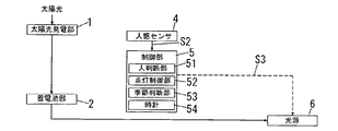
本実施形態の照明装置のブロック構成図を図1に示す。本実施形態の照明装置は、太陽光発電部1と、蓄電池部2と、発電量検知部3と、人感センサ4と、制御部5と、光源6とで構成されている。
(Embodiment)
FIG. 1 shows a block diagram of the illumination device of the present embodiment. The lighting device according to the present embodiment includes a solar
以下に、各部の構成について説明する。 Below, the structure of each part is demonstrated.
太陽光発電部1は、太陽電池で構成されており、太陽光を受光することによって発電する。そして、太陽光発電部1は、発電した電力を蓄電池部2に供給することで、蓄電池部2は充電される。
The solar
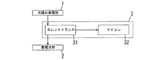
発電量検知部3は、太陽光発電部1の発電量を検知し、検知結果を制御部5に出力している。発電量検知部3は、図2に示すように、カレントトランス31とマイクロコンピュータ32(以下、マイコン32と略称する)とで構成されている。
The power generation
カレントトランス31は、太陽光発電部1と蓄電池部2とを接続する電路に流れる電流を検出し、検出結果をマイコン32に出力する。マイコン32は、A/D変換部としての機能を有しており、カレントトランス31からアナログ値で出力される検出結果を、デジタル信号に変換する。上記構成によって、発電量検出部3は、太陽光発電部1の出力電流を検出することで太陽光発電部1の発電量を検出し、デジタル信号からなる発電量検出信号S1を生成して、この発電量検出信号S1を制御部5に送信する。
The
なお、図3に示すように、カレントトランス31の代わりに電流検出抵抗33を用いてもよい。電流検出抵抗33は、太陽光発電部1と蓄電池部2とを接続する電路に直列接続されている。そして、マイコン32は、電流検出抵抗33の両端電圧を検出し、検出した電圧をA/D変換して発電量検出信号S1を生成して制御部5に送信する。
As shown in FIG. 3, a
人感センサ4は、焦電型の赤外線検出素子(赤外焦動素子)で構成されている。人感センサ4は、所定の検知エリアにおける人から発生する赤外線(熱)、すなわち人と人の背景との温度差を検知しており、温度差を検知することで人を検知する。そして、人感センサ4は、検知エリアにおける人の検知・非検知を示す人体検知信号S2を生成し、この人体検知信号S2を制御部5に送信する。
The
制御部5は、マイクロコンピュータ等で構成されており、人判断部51と、点灯制御部52と、季節判断部53とを備えている。
The
人判断部51は、人感センサ4から送信される人体検知信号S2に基づいて、検知エリアに人が存在するか否かを判断する。
Based on the human body detection signal S2 transmitted from the
点灯制御部52は、発電量検知部3から送信される発電量検出信号S1による昼夜の判断結果と、人判断部51による人の在・不在の判断結果とに基づいて、調光信号S3を生成する。調光信号S3は例えばPWM信号で構成されており、点灯制御部が調光信号S3を光源6に送信することで、光源6を点灯制御する。
The
季節判断部53は、発電量検知部3から送信される発電量検出信号S1に基づいて、現在の季節を判断する。
The
光源6は、蓄電池部2を電源としており、蓄電池部2に充電された電力が供給されることによって点灯する。また、光源6は、点灯回路を備えており、点灯制御部52から送信される調光信号S3に基づいて、点灯・消灯・調光点灯する。なお、光源6は、放電灯,LED,白熱電球などで構成されており、特に種類は限定されない。
The light source 6 uses the
以下に、本実施形態の照明装置における各部の詳細な動作について説明する。 Below, the detailed operation | movement of each part in the illuminating device of this embodiment is demonstrated.
図4に、太陽光発電部1による発電量のグラフを示す。
In FIG. 4, the graph of the electric power generation amount by the solar
季節判断部53は、発電量検出信号S1が示す発電量に基づいて、現在の季節を判断する。季節判断部53には、発電量に対する閾値A1が予め設定されている。また、季節判断部53は、時間を計時するタイマを備えており、発電量が閾値A1以上の時間を昼、発電量が閾値A1未満の時間を夜とし、各々の累積時間を計時して昼時間,夜時間を算出する。そして、季節判断部53は、24時間における、昼時間と夜時間との割合から、現在の季節を判断する。
The
すなわち、太陽光発電部1による発電量の24時間の変化から、太陽が出ている昼間か、太陽が沈んだ夜間かを判断する。夏季は昼間の時間が長く、夜間の時間が短いが、冬季は昼間の時間が短く、夜間の時間が長い。したがって、季節判断部53は、24時間における、昼時間と夜時間との割合から、現在の季節を判断することができる。例えば、季節判断部53は、昼時間が11時間未満の場合は冬季、昼時間が11時間以上,13時間未満の場合は春秋季、昼時間が13時間以上の場合は夏季と判断する。
That is, it is determined from the change in the amount of power generated by the solar
次に、人判断部51について説明する。
Next, the
人判断部51は、人感センサ4から送信される人体検知信号S2に基づいて、検知エリアに人が存在するか否かを判断する。図5に人体検知信号S2の波形図を示す。
Based on the human body detection signal S2 transmitted from the
人感センサ4は、時間t1において、人から発生する赤外線(温度差)を検知し、人体検知信号S2の出力レベルをハイレベルからローレベルに変化させる。また、人感センサ4は、時間t2において、人が非検知となり、検知信号S2の出力レベルをローレベルからハイレベルに変化させる。すなわち、人感センサ4は、人を検知している場合、人体検知信号S2の出力レベルをローレベルとし、人が非検知の場合、人体検知信号S2の出力レベルをハイレベルとする。なお、本実施形態における人を検知している期間(時間t1から時間t2までの期間)をT1とする。
The
人判断部51は、人体検知信号S2の出力レベルをT20(=10ms)毎に検出している。そして、人判断部51は、図5に示すように、人体検知信号S2の出力レベル[ロー]を4回連続で検出すると、検知エリアに人が存在すると判断する。人判断部51が1回目の人体検知信号S2の出力レベル[ロー]を検知してから、4回目の人体検知信号S2の出力レベル[ロー]を検知するまでの期間を判断時間T21とする。すなわち、人感センサ4が人を検知している期間T1が、最短でも判断時間T21よりも長い場合に、人判断部51は検知エリアに人が存在すると判断する。それによって、人判断部51は、より確実に人の在・不在を検出し、誤検出を防止することができる。
The
しかし、本実施形態の人感センサ4は、焦電型の赤外線検出素子で構成されているので、人と人の背景との温度差が小さくなる夏季は、検出精度が低下してしまう。
However, since the
そこで、季節判断部53が夏季と判断した場合、本実施形態の人判断部51は、図6に示すように、人体検知信号S2の出力レベル[ロー]を1回でも検出すると、検知エリアに人が存在すると判断する。すなわち、夏季と判断された場合、人判断部51が用いる判断時間は、判断時間T21より短い判断時間T22となる。なお、この判断時間T22は、人判断部51が人体検知信号S2の出力レベルを検知するのに要する期間である。このように、人感センサ4の検出精度が低下した夏季であっても、人の在・不在を判断する判断時間を短くすることで、人が存在するにもかかわらず、人[不在]と判断する誤判断を防止することができる。
Therefore, when the
なお、本実施形態の人判断部51は、10ms毎に人体検知信号S2の出力レベルを検出しているが、10msに限定するものではない。また、人判断部51は、人体検知信号S2の出力レベル[ロー]を、冬季,春秋季は4回連続、夏季は1回検出することで人が存在すると判断するが、上記回数に限定するものではない。
In addition, although the
次に、点灯制御部52について説明する。
Next, the
点灯制御部52は、発電量検出信号S1による昼夜の判断結果と、人判断部51による人の在・不在の判断結果と、季節判断部53による季節の判断結果とに基づいて、光源6を点灯制御する。
The
点灯制御部52は、発電量検出信号S1が示す発電量を監視しており、発電量が閾値A1以上となると、昼間と判断して光源6を消灯し、発電量が閾値A1未満となると、夜間と判断して光源6を点灯させる。このとき、点灯制御部52は、人判断部51の判断結果に基づいて、光源6の調光率を決定する。点灯制御部52は、人判断部51が人[不在]と判断した場合、光源6を第2の調光率D2で点灯させる。そして、点灯制御部52は、人判断部51が人[在]と判断した場合、予め設定された点灯保持時間T3の間、光源6を第2の調光率D2より高い第1の調光率D1で点灯させる。なお、点灯保持時間T3経過後、点灯制御部52は、人判断部51の判断結果に基づいて、光源6の調光率を再度決定する。このように、本実施形態の点灯制御部52は、夜間となると光源6を点灯させ、検知エリアに人が存在する場合は光源6の調光率を上昇させる。
The
また、点灯制御部52は、季節判断部53による季節の判断結果に基づいて、第1,第2の調光率および、点灯保持時間を変動させる。
Also, the
図7に示すように、点灯制御部52は、季節判断部53が夏季と判断した場合、第1の調光率D1をD11(=100%)、第2の調光率D2をD21(=25%)、点灯保持時間T3をT31(=3分)に設定する。
As illustrated in FIG. 7, when the
点灯制御部52は夜間と判断すると光源6を点灯させる。時間t3以前は、人判断部51は人[不在]と判断しており、点灯制御部52は、光源6を第2の調光率D21(=25%)で点灯させる。そして、時間t3において、人判断部51が人[在]と判断すると、点灯制御部52は、点灯保持時間T31(=3分)の間、光源6を第1の調光率D11(=100%)で点灯させる。そして、時間t3から点灯保持時間T31(=3分)が経過した時間t4以降、点灯制御部52は光源6を再び第2の調光率D21(=25%)で点灯させる。
When the
しかし、夏季は昼時間が長く、蓄電池2に充電される電力が大きいので、上記設定で問題ないが、冬季は昼時間が短く、蓄電池2に充電される電力が夏季に比べて小さい。さらに、冬季は夜間が長いため、光源6を長時間点灯させる必要がある。そのため、特に冬季は光源6を点灯させるための電力が不足するおそれがあった。したがって、冬季および春秋季は、夏季に比べて光源6の消費電力量を低減させる必要がある。
However, since the daytime is long in summer and the electric power charged in the
そこで、図8に示すように、点灯制御部52は、季節判断部53が冬季と判断した場合、第1の調光率D1をD12(=20%)、第2の調光率D2をD22(=5%)、点灯保持時間T3をT32(=1分)に設定する。
Therefore, as shown in FIG. 8, when the
点灯制御部52は夜間と判断すると光源6を点灯させる。時間t3以前は、人判断部51は人[不在]と判断しており、点灯制御部52は、光源6を第2の調光率D22(=5%)で点灯させる。そして、時間t3において、人判断部51が人[在]と判断すると、点灯制御部52は、点灯保持時間T32(=1分)の間、光源6を第1の調光率D12(=20%)で点灯させる。そして、時間t3から点灯保持時間T32が経過した時間t5以降、点灯制御部52は光源6を再び第2の調光率D22(=5%)で点灯させる。
When the
このように、点灯制御部52は、季節判断部53が冬季と判断した場合、夏季と比べて、第1,第2の調光率D1,D2を低くし、点灯保持時間T3を短くする。それによって、冬季は、夏季に比べて光源6の第1,第2の調光率D1,D2が低く、さらに、消費電力が大きい第1の調光率D1で点灯させる点灯保持時間T3が短くなることで、光源6の消費電力量が低減する。そのため、冬季に光源6を点灯するための電力が不足することを防止することができる。
As described above, when the
また、点灯制御部52は、季節判断部53が春秋季と判断した場合、点灯保持時間T3を、T31(3分)とT32(1分)の間である2分と設定する。また、点灯制御部52は、季節判断部53が春秋季と判断した場合、第1の調光率D1をD11(100%)とD12(20%)との間の値、第2の調光率D2をD21(25%)とD22(5%)との間の値に設定する。それによって、日の出から日の入りまでの時間である昼時間が短い季節になるにつれて、光源6の消費電力量を低減させることができる。
On the other hand, when the
また、人と人の背景との温度差が小さくなる夏季は、点灯保持時間T3の経過後に、人判断部51が再度人の在・不在を判断する際に、人が存在するにもかかわらず人不検出となるおそれがある。この場合、光源6の調光率が第1の調光率D11から第2の調光率D21に移行して暗くなってしまった。しかし、本実施形態の点灯制御部52は、季節判断部53が夏季と判断した場合、点灯保持時間T3を冬季よりも長く設定するので、人が存在するにも関わらず暗くなる状態を低減することができる。
In summer, when the temperature difference between the person and the person's background is small, after the lighting holding time T3 has elapsed, the
また、夏季は、人判断部51が人[不在]と判断した場合でも、光源6の調光率は25%であるため、光源6の照射範囲における照度が確保されるので、安全性が向上する。
Further, in the summer, even when the
なお、第1,第2の調光率D1,D2および点灯保持時間T3の具体的な値は、上記に限定するものではない。例えば、夏季における第2の調光率D2を100%(全点灯状態)と設定し、人判断部51の判断結果にかかわらず、夜間に光源6を全点灯するように構成してもよい。また、冬季における第2の調光率D2を0%(消灯状態)と設定し、人判断部51が人[不在]と判断した場合は、光源6を消灯するように構成してもよい。
Note that specific values of the first and second dimming rates D1 and D2 and the lighting holding time T3 are not limited to the above. For example, the second dimming rate D2 in summer may be set to 100% (full lighting state), and the light source 6 may be fully lit at night regardless of the determination result of the
なお、本実施形態では点灯制御部52と季節判断部53には、同一の閾値A1が設定されているが、互いに異なる閾値が設定されていてもよい。
In the present embodiment, the same threshold value A1 is set in the
なお、本実施形態では、点灯制御部52は、季節判断部53による季節の判断結果に基づいて、第1,第2の調光率D1,D2と点灯保持時間T3との両方を変動させているが、いずれか一方のみを変動させてもよい。
In the present embodiment, the
また、本実施形態では、発電量検知部3が送信する発電量検出信号S1が示す太陽光発電部1の発電量に基づいて、季節判断部53は季節を判断し、点灯制御部52は昼間と夜間とを判別していた。
In the present embodiment, the
しかし、図9に示すように、発電量検知部3の代わりに、計時機能を有する時計54(計時部)を制御部5に設けてもよい。季節判断部53は、時計54が示す現在の日付から季節を判断する。また、点灯制御部52は、時計54が示す現在の日付および時間から、昼間と夜間とを判断する。
However, as shown in FIG. 9, a clock 54 (timer) having a timekeeping function may be provided in the
また、図10に示すように、発電量検知部3の代わりに明るさセンサ7を設けてもよい。明るさセンサ7は、フォトダイオード等で構成されており、照明装置周辺(屋外)の照度を検出している。季節判断部53には、予め照度閾値が設定されており、明るさセンサ7の検出結果から、照度閾値以上の昼時間と、照度閾値未満の夜時間とし、所定期間内における各々の累積時間の割合から季節を判断する。また、点灯制御部52には、予め照度閾値が設定されており、明るさセンサ7の検出結果から、照度閾値未満となると夜間であると判断し、光源6を点灯させる。
As shown in FIG. 10, a brightness sensor 7 may be provided instead of the power generation
また、本実施形態の人感センサ4は、焦電型の赤外線検出素子で構成されているが、ミリ波等を用いる超音波センサまたは、カメラを用いる画像センサで構成されていてもよい。
In addition, the
人感センサ4が超音波センサで構成されている場合、超音波センサが、ミリ波などの超音波信号を送信し、その反射波を受信する。そして、人判断部51は、超音波信号の送信から反射波の受信までの時間差に基づいて、検知エリアの人の在・不在を判断する。
When the
また、人感センサ4が画像センサで構成されている場合、画像センサが、検知エリアを撮像する。そして、人判断部51が、撮像結果を画像処理することで、検知エリアの人の在・不在を判断する。
Moreover, when the
人感センサ4を焦電型の赤外線検出素子で構成した場合は、人の検出精度が季節による影響を受けるが、超音波センサおよび画像センサの検出精度は、季節による影響を受けない。したがって、人感センサ4を超音波センサまたは画像センサで構成することによって、人判断部51の人の在・不在を判断する判断時間を季節に応じて変更する必要がないので、人判断部51の制御を簡易化することができる。
When the
本実施形態の照明装置は、例えば図11に示すような街路灯10に用いられる。支柱11の上部に太陽光発電部1が設けられ、支柱11の下方に設けられた筐体12の内部に蓄電池部2と発電量検知部3と制御部5とが設けられている。また、支柱11には、人感センサ4と光源6とが設けられている。屋外に設置される街路灯10を本実施形態の照明装置を用いて構成することによって、季節判断部53が判断した季節の昼時間が短くなるにつれて、第1,第2の調光率を低く、点灯保持時間を短くし、冬季における光源6の消費電力を低減させることができる。それによって、冬季に光源6を点灯するための電力が不足することを防止することができる。
The illuminating device of this embodiment is used for the
1 太陽光発電部
2 蓄電池部
3 発電量検知部
4 人感センサ
5 制御部
6 光源
51 人判断部
52 点灯制御部
53 季節判断部
DESCRIPTION OF
Claims (7)
前記太陽光発電部で発電した電力を蓄電する蓄電池部と、
前記蓄電池部を電源として点灯する光源と、
人を検知する人感センサと、
前記人感センサの検知結果に基づき、人の在・不在を判断する人判断部と、
現在の季節を判断する季節判断部と、
前記人判断部が人が存在すると判断した場合、所定の点灯保持時間の間、前記光源を所定の調光率で点灯させる点灯制御部とを備え、
前記点灯制御部は、前記季節判断部が判断した季節に基づいて、昼時間が短い季節における前記光源の消費電力量を、前記季節判断部が判断した昼時間が長い季節における前記光源の消費電力量よりも小さくすることを特徴とする照明装置。 A solar power generation unit that generates power by receiving sunlight;
A storage battery unit for storing electric power generated by the solar power generation unit;
A light source that is turned on using the storage battery unit as a power source;
A human sensor that detects people,
Based on the detection result of the human sensor, a person determination unit that determines the presence / absence of a person,
A season determination unit that determines the current season;
A lighting control unit that turns on the light source at a predetermined dimming rate during a predetermined lighting holding time when the person determination unit determines that a person exists;
Based on the season determined by the season determination unit, the lighting control unit calculates the power consumption of the light source in the season with a short daytime, and the power consumption of the light source in the season with a long daytime determined by the season determination unit. A lighting device characterized by being smaller than the amount.
前記人判断部は、前記人感センサが、所定の判断時間の間、人を検知している場合、人が存在すると判断し、前記季節判断部が判断した季節に基づいて、昼時間が長い季節における前記判断時間を、前記季節判断部が判断した昼時間が短い季節における前記判断時間よりも短くすることを特徴とする請求項1乃至3のいずれか1項に記載の照明装置。 The human sensor is composed of a pyroelectric infrared detection element,
The person determination unit determines that a person is present when the human sensor detects a person for a predetermined determination time, and the daytime is long based on the season determined by the season determination unit. The lighting device according to any one of claims 1 to 3, wherein the determination time in a season is shorter than the determination time in a season in which the daylight time determined by the season determination unit is short.
前記季節判断部は、前記発電量検知部の検知結果に基づいて、季節を判断することを特徴とする請求項1乃至4のいずれか1項に記載の照明装置。 A power generation amount detection unit that detects a power generation amount by the solar power generation unit,
The lighting device according to claim 1, wherein the season determination unit determines a season based on a detection result of the power generation amount detection unit.
前記季節判断部は、前記計時部の計時結果に基づいて、季節を判断することを特徴とする請求項1乃至4のいずれか1項に記載の照明装置。 It has a timekeeping part with a timekeeping function,
5. The lighting device according to claim 1, wherein the season determination unit determines a season based on a timing result of the timing unit.
前記季節判断部は、所定期間内に前記明るさセンサが検知する照度が所定の閾値以上となる累積時間を計時しており、当該累積時間に基づいて季節を判断することを特徴とする請求項1乃至4のいずれか1項に記載の照明装置。 It has a brightness sensor that detects outdoor brightness,
The season determination unit measures a cumulative time during which the illuminance detected by the brightness sensor is equal to or greater than a predetermined threshold within a predetermined period, and determines the season based on the cumulative time. The lighting device according to any one of 1 to 4.
Priority Applications (4)
| Application Number | Priority Date | Filing Date | Title |
|---|---|---|---|
| JP2010230875A JP2012084441A (en) | 2010-10-13 | 2010-10-13 | Lighting system |
| CN2011103067531A CN102573204A (en) | 2010-10-13 | 2011-10-11 | Illumination device |
| EP11184910.5A EP2442014B1 (en) | 2010-10-13 | 2011-10-12 | Illumination device |
| US13/271,405 US20120091901A1 (en) | 2010-10-13 | 2011-10-12 | Illumination device |
Applications Claiming Priority (1)
| Application Number | Priority Date | Filing Date | Title |
|---|---|---|---|
| JP2010230875A JP2012084441A (en) | 2010-10-13 | 2010-10-13 | Lighting system |
Publications (1)
| Publication Number | Publication Date |
|---|---|
| JP2012084441A true JP2012084441A (en) | 2012-04-26 |
Family
ID=44862539
Family Applications (1)
| Application Number | Title | Priority Date | Filing Date |
|---|---|---|---|
| JP2010230875A Pending JP2012084441A (en) | 2010-10-13 | 2010-10-13 | Lighting system |
Country Status (4)
| Country | Link |
|---|---|
| US (1) | US20120091901A1 (en) |
| EP (1) | EP2442014B1 (en) |
| JP (1) | JP2012084441A (en) |
| CN (1) | CN102573204A (en) |
Families Citing this family (8)
| Publication number | Priority date | Publication date | Assignee | Title |
|---|---|---|---|---|
| JP2013008460A (en) * | 2011-06-22 | 2013-01-10 | Panasonic Corp | Lighting device |
| JP5861108B2 (en) * | 2011-10-24 | 2016-02-16 | パナソニックIpマネジメント株式会社 | Lighting control device, lighting device and lighting system |
| CN102495281B (en) * | 2011-12-14 | 2013-09-04 | 广东易事特电源股份有限公司 | Method for measuring phasor frequency of power system |
| CN102833911B (en) * | 2012-07-12 | 2016-01-20 | 黄金碧 | Power Supply Street Lighting System |
| FR3000623B1 (en) * | 2012-12-28 | 2018-04-27 | Sunna Design | METHOD FOR DYNAMICALLY CONTROLLING AN ELECTRICAL EQUIPMENT |
| JP6156010B2 (en) * | 2013-09-20 | 2017-07-05 | 東芝ライテック株式会社 | Lighting control system |
| GB201503332D0 (en) | 2015-02-27 | 2015-04-15 | Bransfield Garth Simon And Sales Michael J And Azuri Technologies Ltd And Preston Nigel And Barclay | Solar home system |
| CN111246618A (en) * | 2020-03-12 | 2020-06-05 | 江西五和电气有限公司 | Photovoltaic LED lighting product capable of changing color temperature according to seasons |
Citations (9)
| Publication number | Priority date | Publication date | Assignee | Title |
|---|---|---|---|---|
| JPS5820493U (en) * | 1981-07-31 | 1983-02-08 | 松下電工株式会社 | outdoor lighting |
| JPH05159885A (en) * | 1991-04-30 | 1993-06-25 | Mitsubishi Plastics Ind Ltd | Lighting system using solar cells |
| JPH0721813A (en) * | 1993-06-30 | 1995-01-24 | Masuo:Kk | Automatic gas lamp flashing device |
| JP2004241217A (en) * | 2003-02-05 | 2004-08-26 | Yamatake Corp | Outdoor lighting equipment |
| JP2006092944A (en) * | 2004-09-24 | 2006-04-06 | Matsushita Electric Works Ltd | Security lighting setup |
| JP2008084588A (en) * | 2006-09-26 | 2008-04-10 | Matsushita Electric Works Ltd | Lighting control system |
| JP2008235045A (en) * | 2007-03-22 | 2008-10-02 | Gunma Prefecture | LIGHT EMITTING DEVICE, ILLUMINATION DEVICE, LIGHT EMITTING SYSTEM, LIGHT EMITTING PATTERN CHANGE METHOD, AND LIGHT EMITTING SYSTEM LIGHT EMITTING METHOD |
| JP2009266605A (en) * | 2008-04-24 | 2009-11-12 | Panasonic Electric Works Co Ltd | Automatic dimming system |
| JP2010033811A (en) * | 2008-07-28 | 2010-02-12 | Panasonic Electric Works Co Ltd | Illumination device |
Family Cites Families (12)
| Publication number | Priority date | Publication date | Assignee | Title |
|---|---|---|---|---|
| CA1228392A (en) * | 1983-05-20 | 1987-10-20 | Francis M. Watson | Skylight sensor and control system |
| US5952081A (en) * | 1997-10-01 | 1999-09-14 | Lorenz; Werner | Pane with seasonally adapted solar radiation transmission |
| US7417378B2 (en) * | 2002-11-06 | 2008-08-26 | Jihn-Kuk Kim | Apparatus for controlling lighting lamp with security function and lighting control method using the same |
| US7417397B2 (en) * | 2004-05-06 | 2008-08-26 | Mechoshade Systems, Inc. | Automated shade control method and system |
| US20120143383A1 (en) * | 2007-02-02 | 2012-06-07 | Inovus Solar, Inc. | Energy-efficient utility system utilizing solar-power |
| WO2010057138A2 (en) * | 2008-11-14 | 2010-05-20 | Inovus Solar, Inc. | Energy-efficient solar-powered outdoor lighting |
| US8255090B2 (en) * | 2008-02-01 | 2012-08-28 | Energyhub | System and method for home energy monitor and control |
| US20090196041A1 (en) * | 2008-02-05 | 2009-08-06 | Joseph Peter D | Energy efficient light |
| CN201213324Y (en) * | 2008-05-29 | 2009-03-25 | 保定市宝新世纪路灯厂 | Multifunctional controller for solar energy lamp |
| CN201297559Y (en) * | 2008-07-11 | 2009-08-26 | 上海信德太阳能科技发展有限公司 | Solar energy controller |
| US8232909B2 (en) * | 2008-09-30 | 2012-07-31 | Cooper Technologies Company | Doppler radar motion detector for an outdoor light fixture |
| CN201479430U (en) * | 2009-08-24 | 2010-05-19 | 珈伟太阳能科技(上海)有限公司 | An intelligent solar sensor lamp circuit that automatically senses seasonal changes |
-
2010
- 2010-10-13 JP JP2010230875A patent/JP2012084441A/en active Pending
-
2011
- 2011-10-11 CN CN2011103067531A patent/CN102573204A/en active Pending
- 2011-10-12 US US13/271,405 patent/US20120091901A1/en not_active Abandoned
- 2011-10-12 EP EP11184910.5A patent/EP2442014B1/en not_active Not-in-force
Patent Citations (9)
| Publication number | Priority date | Publication date | Assignee | Title |
|---|---|---|---|---|
| JPS5820493U (en) * | 1981-07-31 | 1983-02-08 | 松下電工株式会社 | outdoor lighting |
| JPH05159885A (en) * | 1991-04-30 | 1993-06-25 | Mitsubishi Plastics Ind Ltd | Lighting system using solar cells |
| JPH0721813A (en) * | 1993-06-30 | 1995-01-24 | Masuo:Kk | Automatic gas lamp flashing device |
| JP2004241217A (en) * | 2003-02-05 | 2004-08-26 | Yamatake Corp | Outdoor lighting equipment |
| JP2006092944A (en) * | 2004-09-24 | 2006-04-06 | Matsushita Electric Works Ltd | Security lighting setup |
| JP2008084588A (en) * | 2006-09-26 | 2008-04-10 | Matsushita Electric Works Ltd | Lighting control system |
| JP2008235045A (en) * | 2007-03-22 | 2008-10-02 | Gunma Prefecture | LIGHT EMITTING DEVICE, ILLUMINATION DEVICE, LIGHT EMITTING SYSTEM, LIGHT EMITTING PATTERN CHANGE METHOD, AND LIGHT EMITTING SYSTEM LIGHT EMITTING METHOD |
| JP2009266605A (en) * | 2008-04-24 | 2009-11-12 | Panasonic Electric Works Co Ltd | Automatic dimming system |
| JP2010033811A (en) * | 2008-07-28 | 2010-02-12 | Panasonic Electric Works Co Ltd | Illumination device |
Also Published As
| Publication number | Publication date |
|---|---|
| US20120091901A1 (en) | 2012-04-19 |
| EP2442014A1 (en) | 2012-04-18 |
| EP2442014B1 (en) | 2015-07-08 |
| CN102573204A (en) | 2012-07-11 |
Similar Documents
| Publication | Publication Date | Title |
|---|---|---|
| JP2012084441A (en) | Lighting system | |
| US9185777B2 (en) | Ambient light control in solid state lamps and luminaires | |
| EP2878176B1 (en) | Apparatus and method of operating a luminaire | |
| US20170055324A1 (en) | Apparatus, retrofit kit, and method of energy efficient illumination using adjustment schedules | |
| JP2012094273A (en) | Lighting system | |
| JP2013229298A (en) | Illumination device | |
| JP5849210B2 (en) | Lighting device with solar power generation function | |
| WO2011083424A1 (en) | Battery operated devices | |
| KR100927745B1 (en) | Automatic lighting device and method for each step of setting and controlling the standard illuminance value automatically | |
| CN201412709Y (en) | An intelligent energy-saving lighting system | |
| JP2010212232A (en) | Lighting system and lighting control method | |
| EP2594844A1 (en) | Power generating lamp and illumination appliance | |
| JP5233042B2 (en) | LED drive circuit | |
| JP5308070B2 (en) | Lighting device | |
| CN107658958B (en) | Photoelectric system and photoelectric control method | |
| JP5308090B2 (en) | Lighting device | |
| WO2010150701A1 (en) | Automatic flashing control device for illumination | |
| JP5344762B2 (en) | lighting equipment | |
| EP2908106B1 (en) | Light measurement device for lighting element | |
| RU59205U1 (en) | OFFLINE LIGHTING | |
| JP5495371B2 (en) | lighting equipment | |
| Pachamanov et al. | Management of street lighting by relative value of the rate of change of natural light | |
| JP5849209B2 (en) | Lighting device with solar power generation function | |
| KR20110050006A (en) | Solar street light | |
| JP6477093B2 (en) | LED lighting device and lighting device |
Legal Events
| Date | Code | Title | Description |
|---|---|---|---|
| A621 | Written request for application examination |
Free format text: JAPANESE INTERMEDIATE CODE: A621 Effective date: 20130911 |
|
| A977 | Report on retrieval |
Free format text: JAPANESE INTERMEDIATE CODE: A971007 Effective date: 20140226 |
|
| A131 | Notification of reasons for refusal |
Free format text: JAPANESE INTERMEDIATE CODE: A131 Effective date: 20140304 |
|
| A521 | Written amendment |
Free format text: JAPANESE INTERMEDIATE CODE: A523 Effective date: 20140507 |
|
| A131 | Notification of reasons for refusal |
Free format text: JAPANESE INTERMEDIATE CODE: A131 Effective date: 20140701 |
|
| A711 | Notification of change in applicant |
Free format text: JAPANESE INTERMEDIATE CODE: A711 Effective date: 20141007 |
|
| A02 | Decision of refusal |
Free format text: JAPANESE INTERMEDIATE CODE: A02 Effective date: 20141104 |