JP4069010B2 - Air conditioning equipment and energy recovery device mounting method - Google Patents
Air conditioning equipment and energy recovery device mounting method Download PDFInfo
- Publication number
- JP4069010B2 JP4069010B2 JP2003136161A JP2003136161A JP4069010B2 JP 4069010 B2 JP4069010 B2 JP 4069010B2 JP 2003136161 A JP2003136161 A JP 2003136161A JP 2003136161 A JP2003136161 A JP 2003136161A JP 4069010 B2 JP4069010 B2 JP 4069010B2
- Authority
- JP
- Japan
- Prior art keywords
- water
- pipe
- air conditioning
- energy recovery
- recovery device
- Prior art date
- Legal status (The legal status is an assumption and is not a legal conclusion. Google has not performed a legal analysis and makes no representation as to the accuracy of the status listed.)
- Expired - Lifetime
Links
Images


Classifications
-
- F—MECHANICAL ENGINEERING; LIGHTING; HEATING; WEAPONS; BLASTING
- F24—HEATING; RANGES; VENTILATING
- F24F—AIR-CONDITIONING; AIR-HUMIDIFICATION; VENTILATION; USE OF AIR CURRENTS FOR SCREENING
- F24F12/00—Use of energy recovery systems in air conditioning, ventilation or screening
-
- F—MECHANICAL ENGINEERING; LIGHTING; HEATING; WEAPONS; BLASTING
- F24—HEATING; RANGES; VENTILATING
- F24F—AIR-CONDITIONING; AIR-HUMIDIFICATION; VENTILATION; USE OF AIR CURRENTS FOR SCREENING
- F24F11/00—Control or safety arrangements
- F24F11/70—Control systems characterised by their outputs; Constructional details thereof
- F24F11/80—Control systems characterised by their outputs; Constructional details thereof for controlling the temperature of the supplied air
- F24F11/83—Control systems characterised by their outputs; Constructional details thereof for controlling the temperature of the supplied air by controlling the supply of heat-exchange fluids to heat-exchangers
- F24F11/84—Control systems characterised by their outputs; Constructional details thereof for controlling the temperature of the supplied air by controlling the supply of heat-exchange fluids to heat-exchangers using valves
-
- F—MECHANICAL ENGINEERING; LIGHTING; HEATING; WEAPONS; BLASTING
- F24—HEATING; RANGES; VENTILATING
- F24F—AIR-CONDITIONING; AIR-HUMIDIFICATION; VENTILATION; USE OF AIR CURRENTS FOR SCREENING
- F24F3/00—Air-conditioning systems in which conditioned primary air is supplied from one or more central stations to distributing units in the rooms or spaces where it may receive secondary treatment; Apparatus specially designed for such systems
- F24F3/06—Air-conditioning systems in which conditioned primary air is supplied from one or more central stations to distributing units in the rooms or spaces where it may receive secondary treatment; Apparatus specially designed for such systems characterised by the arrangements for the supply of heat-exchange fluid for the subsequent treatment of primary air in the room units
-
- F—MECHANICAL ENGINEERING; LIGHTING; HEATING; WEAPONS; BLASTING
- F24—HEATING; RANGES; VENTILATING
- F24F—AIR-CONDITIONING; AIR-HUMIDIFICATION; VENTILATION; USE OF AIR CURRENTS FOR SCREENING
- F24F11/00—Control or safety arrangements
- F24F11/70—Control systems characterised by their outputs; Constructional details thereof
- F24F11/80—Control systems characterised by their outputs; Constructional details thereof for controlling the temperature of the supplied air
- F24F11/83—Control systems characterised by their outputs; Constructional details thereof for controlling the temperature of the supplied air by controlling the supply of heat-exchange fluids to heat-exchangers
-
- Y—GENERAL TAGGING OF NEW TECHNOLOGICAL DEVELOPMENTS; GENERAL TAGGING OF CROSS-SECTIONAL TECHNOLOGIES SPANNING OVER SEVERAL SECTIONS OF THE IPC; TECHNICAL SUBJECTS COVERED BY FORMER USPC CROSS-REFERENCE ART COLLECTIONS [XRACs] AND DIGESTS
- Y02—TECHNOLOGIES OR APPLICATIONS FOR MITIGATION OR ADAPTATION AGAINST CLIMATE CHANGE
- Y02E—REDUCTION OF GREENHOUSE GAS [GHG] EMISSIONS, RELATED TO ENERGY GENERATION, TRANSMISSION OR DISTRIBUTION
- Y02E10/00—Energy generation through renewable energy sources
- Y02E10/20—Hydro energy
-
- Y—GENERAL TAGGING OF NEW TECHNOLOGICAL DEVELOPMENTS; GENERAL TAGGING OF CROSS-SECTIONAL TECHNOLOGIES SPANNING OVER SEVERAL SECTIONS OF THE IPC; TECHNICAL SUBJECTS COVERED BY FORMER USPC CROSS-REFERENCE ART COLLECTIONS [XRACs] AND DIGESTS
- Y02—TECHNOLOGIES OR APPLICATIONS FOR MITIGATION OR ADAPTATION AGAINST CLIMATE CHANGE
- Y02E—REDUCTION OF GREENHOUSE GAS [GHG] EMISSIONS, RELATED TO ENERGY GENERATION, TRANSMISSION OR DISTRIBUTION
- Y02E60/00—Enabling technologies; Technologies with a potential or indirect contribution to GHG emissions mitigation
- Y02E60/16—Mechanical energy storage, e.g. flywheels or pressurised fluids
-
- Y—GENERAL TAGGING OF NEW TECHNOLOGICAL DEVELOPMENTS; GENERAL TAGGING OF CROSS-SECTIONAL TECHNOLOGIES SPANNING OVER SEVERAL SECTIONS OF THE IPC; TECHNICAL SUBJECTS COVERED BY FORMER USPC CROSS-REFERENCE ART COLLECTIONS [XRACs] AND DIGESTS
- Y10—TECHNICAL SUBJECTS COVERED BY FORMER USPC
- Y10S—TECHNICAL SUBJECTS COVERED BY FORMER USPC CROSS-REFERENCE ART COLLECTIONS [XRACs] AND DIGESTS
- Y10S165/00—Heat exchange
- Y10S165/902—Heat storage
Landscapes
- Engineering & Computer Science (AREA)
- Chemical & Material Sciences (AREA)
- Combustion & Propulsion (AREA)
- Mechanical Engineering (AREA)
- General Engineering & Computer Science (AREA)
- Other Liquid Machine Or Engine Such As Wave Power Use (AREA)
Description
【0001】
【発明の属する技術分野】
本発明は、空調設備及びエネルギー回収装置の取付方法を提供する技術に関する。
【0002】
【従来の技術】
水蓄熱式空調設備の一般的な形態としては、図9に示すように、蓄熱槽6を有し、蓄熱槽6の水をポンプ7で熱源機またはファンコイルなどの空調負荷(A.H.)9に送水し、空調負荷9を通過した水が還水配管10により前記蓄熱槽6へ導かれている。これを開放還水法と呼ぶ。開放還水法は実揚程が20mより低い場合に用いられる。空調が停止すると送水ポンプからの給水が止められるが、開放還水方式では垂直に立ち上がっている還水配管内の水は重力により自由落下、即ち落水する。落水によるサイホン効果で配管内が負圧になり空洞を生じて騒音・振動・腐食が発生する。これを防止するためバキュームブレーカ12aを設置して配管内が負圧になることを防止する。開放還水方式水蓄熱式空調設備のエネルギー回収装置として特許文献1が開示されている。その構造を図11に示す。ビルの地下部分に水蓄熱槽を有し、蓄熱槽の水をポンプで屋上の熱源機に送水するとともに、別のポンプでは各階の空調負荷に蓄熱槽の水を送水している。空調負荷に送水された水は還水配管を通って地下に設置された蓄熱槽に戻っている。還水配管の途中の三階部分と地下一階部分にエネルギー回収装置が設けられている。
【0003】
【特許文献1】
特開昭63−297949号公報
【0004】
【発明が解決しようとする課題】
一方、近年のビル高層化に伴い、水蓄熱式空調設備も5〜10階程度のビルに適用されている。この場合実揚程は20mを超えるため、開放還水法では落水時の振動・騒音が大きくなり問題がある。これを防ぐため、還水配管10の途中の蓄熱槽6に戻る手前に落水防止弁11を設けて落水そのものを防止する。これが満水還水法であり、一般的には図10に示す形態になっている。
【0005】
落水防止弁11は圧力調整弁の一つであり、設定圧力より大きな圧力が作用すると弁が開放し水が弁を通過する。一方、空調を停止し送水ポンプ7からの給水が止まった場合は、速やかに弁を閉じて落水を防止する。送水ポンプ7からの給水が止まってから落水防止弁11が閉止するまでの時間(3〜10秒)は、開放還水法と同様に垂直に立ち上がっている還水配管10内の水は重力により自由落下、即ち落水する。このときに配管内が負圧になることを防止するため、チャッキ弁12bを介してサージタンク13が設けられている。落水防止弁11が閉止するまでの間はサージタンク13から水が補給され配管内の圧力が負圧になることを防止する。
【0006】
空調が停止され送水ポンプ7からの給水が止まったときに落水防止弁11は還水配管10内の落水を防止しなければならないから、落水防止弁11の設定圧力は弁が閉止した状態で弁に作用する圧力よりも僅かに大きくする必要がある。送水ポンプ7が停止しているときに落水防止弁11へ作用する圧力は、還水配管10内の水の持つ位置エネルギー、即ち落水防止弁11からサージタンク13の水面までの高さ、実揚程になる。言いかえれば落水防止弁11は実揚程に相当する抵抗を持っていることと同じである。つまり、空調が運転されて送水ポンプ7が給水しているときに、送水ポンプ7によって空調設備配管の最上部まで押し上げられた水の持つ位置エネルギーは、落水防止弁11を通過するときの落水防止弁11の抵抗に消費される。したがって、落水防止弁11の下流側の還水にはエネルギーが残っていないのでエネルギー回収装置を取り付けることは出来ない。
【0007】
一方、落水防止弁11の上流側にエネルギー回収装置を取付けた場合は、還水の位置エネルギーが落水防止弁11の手前でエネルギー回収装置に吸収されてなくなってしまい、落水防止弁11の抵抗に打ち勝って流れることができないから、空調設備は正常に動作することができない。
【0008】
また、落水防止弁11の上流側にエネルギー回収装置を取付けた状態で空調設備を稼動させるためには送水ポンプ7の動力を増大しなければならず、省エネルギーに逆行すると言う問題がある。
【0009】
また、落水防止弁11の上流側にエネルギー回収装置を取付けた場合に、落水防止弁の設定圧力を小さく、即ち落水防止弁11の抵抗を小さくすることで、送水ポンプ7の動力増加を抑えることが出来るようになるが、しかし、反対に空調を停止した場合は還水の持つ実揚程を落水防止弁11は支えられないため、落水してしまう問題がある。なお、落水防止弁は空調設備の地下等に設置されており、取り外すことは困難である。
【0010】
さらに、エネルギー回収装置が故障した場合には、還水配管内に障害物が発生したのと同じ状態になるため、空調設備は正常に動作することができない。
【0011】
本発明は、このような実状に鑑みてなされたもので、その目的は落水防止弁付水蓄熱式等の空調設備においても水力エネルギーを回収でき、また、空調負荷の変動に伴う流量変化に対応できるエネルギー回収装置の運転方法を有し、また、エネルギー回収装置が故障した場合でも空調設備が正常動作するビルの未利用エネルギーを回収することができる空調設備及びエネルギー回収装置の取付方法を提供することにある。
【0012】
【課題を解決するための手段】
上記目的を達成するために、本発明の空調設備は、水蓄熱槽等の水槽を有し、前記水槽の水をポンプで熱源機またはファンコイルなどの空調負荷に送水し、前記空調負荷を通過した水が還水配管により前記水槽へ導かれており、前記還水配管に設けた落水防止弁を通って前記水槽へ戻る空調設備において、前記落水防止弁の上流の前記還水配管から前記水層への分岐配管を設け、前記分岐配管の途中にエネルギー回収装置を取りつけた。これにより、還水は前記分岐配管を通って前記水槽へ戻るので、前記落水防止弁の抵抗で還水の持つ位置エネルギーが浪費されることがない。したがって、前記分岐配管の途中に取付けたエネルギー回収装置で位置エネルギーを回収することが出来る。さらに、エネルギー回収装置が故障し障害物となって分岐配管を通過する流量が減少する場合でも、既存設備の還水配管の落水防止弁を通過して流れるので、空調設備の動作に影響を与えることがない。
【0013】
また、本発明の空調設備は、水槽を有し、前記水槽の水をポンプで熱源機またはファンコイルなどの空調負荷に送水し、前記空調負荷を通過した水が還水配管により前記水槽へ導かれており、前記還水配管に設けた落水防止弁を通って前記水槽へ戻る空調設備において、前記落水防止弁の上流の還水配管から前記水槽への分岐配管を設け、前記分岐配管の途中にエネルギー回収装置を取付け、前記エネルギー回収装置の下流側に制御弁を設けた。これにより、還水は前記分岐配管を通って前記水槽へ戻るので、前記落水防止弁の抵抗で還水の持つ位置エネルギーが浪費されることがなく、前記分岐配管の途中に取付けたエネルギー回収装置で還水の持つ位置エネルギーを回収することが出来る。また、空調設備が停止した場合に制御弁を閉じて分岐配管の落水を防止することが出来る。
【0014】
また、本発明の空調設備のエネルギー回収装置の運転方法は、水槽を有し、前記水槽の水をポンプで熱源機またはファンコイルなどの空調負荷に送水し、前記空調負荷を通過した水が還水配管により前記水槽へ導かれており、前記還水配管に設けた落水防止弁を通って前記水槽へ戻る水蓄熱式等の空調設備において、前記落水防止弁の上流の前記還水配管から前記水層への分岐配管を設け、前記分岐配管の途中にエネルギー回収装置を取りつけ、前記エネルギー回収装置を通過する流量が変化した場合に、前記エネルギー回収装置の入口圧力が、前記エネルギー回収装置を定格流量で運転したときの前記エネルギー回収装置の入口圧力に対し、所定の比率幅以内に収まるように、前記エネルギー回収装置の運転制御を行う。これにより、前記還水配管内の圧力が適切に保たれるので、前記還水配管内が負圧になり空洞を生じて騒音・振動・腐食が発生することを防止できる。
【0015】
また、水槽を有し、前記水槽の水をポンプで熱源機またはファンコイルなどの空調負荷に送水し、前記空調負荷を通過した水が還水配管により前記水槽へ導かれており、前記還水配管に設けた落水防止弁を通って前記水槽へ戻る水蓄熱式等の空調設備において、前記落水防止弁の上流の前記還水配管から前記水槽への分岐配管を設け、前記分岐配管の途中にエネルギー回収装置を取付け、前記エネルギー回収装置の下流側に制御弁を設け、前記エネルギー回収装置を通過する流量が変化した場合に、前記エネルギー回収装置の入口圧力が、前記エネルギー回収装置を定格流量で運転したときの前記エネルギー回収装置の入口圧力に対し、所定の比率幅以内に収まるように、前記エネルギー回収装置の運転状態と前記制御弁を調節する。これにより、空調設備の稼動中は前記還水配管内の圧力が適切に保たれるので、前記還水配管内が負圧になり空洞を生じて騒音・振動・腐食が発生することを防止できる。また、空調設備が停止した場合に制御弁を閉じて還水配管の落水を防止することが出来る。
【0016】
また、本発明に係るエネルギー回収装置は、遠心形羽根車を持つ水車とブラシレス永久磁石同期発電機と前記発電機を制御する発電機コントローラで構成されているので、発電機コントローラで発電機の回転速度を調節することにより、発電機に直結した水車の回転速度を調節することが出来る。したがって、遠心形羽根車を有する水車の特性、即ち、回転速度によって水車を通過する流量が変化する特性を活用して、水車を通過する流量の変化に対応することが出来る。これにより、還水配管内が負圧になり空洞を生じて騒音・振動・腐食が発生することを防止できる。
【0017】
また、本発明に係るエネルギー回収装置は、前記エネルギー回収装置の下流側の配管口径が、前記エネルギー回収装置の上流側の配管口径よりも小さいので、前記エネルギー回収装置の下流側に設ける制御弁を小さくすることが出来、廉価なエネルギー回収装置を提供することが出来る。
【0018】
【発明の実施の形態】
本発明の実施の形態を説明する。
本発明の空調設備及びエネルギー回収装置の実施例について、図1〜図8を用いて説明する。図1は、第1実施例の空調設備の構成説明図である。図2は、第2実施例の空調設備の構成説明図である。図3は、第3実施例の空調設備の構成説明図である。図4は、第4実施例の空調設備の構成説明図である。図5は、第4実施例で使用する羽根車の水流状況を示す説明図である。図6は、第4実施例で使用するフランシス水車発電機の特性説明図である。図7は、第4実施例で使用するフランシス水車発電機の特性説明図である。図8は、第4実施例で使用する制御弁の特性説明図である。
【0019】
第1実施例を説明する。図1は本実施例によるエネルギー回収装置を取付けた水蓄熱式空調設備である。蓄熱槽6から配管が送水ポンプ7に繋がっており、送水ポンプ7からの配管は空調機器9に繋がっている。空調機器9からの配管は還水配管10に繋がっている。還水配管10は上部にチャッキ弁12を介してサージタンク13に繋がっている。還水配管10の下部は蓄熱槽6に繋がっている。還水配管10の途中の蓄熱槽に戻る手前に落水防止弁11が設置されており、設定圧力はエネルギー回収装置を取りつける前と同じに設定してある。落水防止弁11の上流側から分岐配管4が設けられ蓄熱槽6へ繋がっている。分岐配管4には手動弁5が設けられている。また、分岐配管4に設けられた手動弁5の下流には遠心形羽根車を持つフランシス水車1が設置されている。フランシス水車1にはブラシレス永久磁石同期発電機2が直結されており、エネルギー回収装置100を構成している。
【0020】
蓄熱槽6の水は送水ポンプ7で上部の空調機器9に送られる。空調機器9で熱交換した水は位置エネルギーを持っており、還水配管10を通って蓄熱槽6に向かって落下する。還水配管10の下部に設けられている落水防止弁11の設定圧力、即ち水が落水防止弁11を通過するための抵抗は、空調設備が停止して送水ポンプからの給水が止まったときに落水防止弁11が閉じられるように位置エネルギーに相当する圧力ヘッドよりも僅かに大きく設定されている。したがって、還水配管10の水は抵抗の大きい落水防止弁11を通過しないで、落水防止弁11の上流に設けられた分岐配管4に流れる。分岐配管4に設けられた手動弁5は全開の状態に設定されているので、手動弁5の抵抗はない。したがって、手動弁5の下流に設置されているエネルギー回収装置100で、還水の持つ位置エネルギーの殆どを回収することが出来る。
【0021】
また、エネルギー回収装置100は分岐配管4に設けられており、還水配管10には落水防止弁11が設けられているので、エネルギー回収装置100が何らかの影響で故障し、水が水車1を通過するときの抵抗が大きくなった場合でも、水は落水防止弁11を通過して蓄熱槽6に戻るので、空調設備に支障をきたすことはない。さらに、還水配管10とエネルギー回収装置100の間に手動弁5が設けられているので、エネルギー回収装置100をメンテナンスする場合でも、手動弁5を閉じることで水は落水防止弁11を通過して蓄熱槽6に戻るので、空調設備に支障をきたすことはない。
【0022】
第2実施例を説明する。図2は本実施例によるエネルギー回収装置を取付けた水蓄熱式空調設備である。蓄熱槽6から配管が送水ポンプ7に繋がっており、送水ポンプ7からの配管は空調機器9に繋がっている。空調機器9からの配管は還水配管10に繋がっている。還水配管10は上部にキャッキ弁12を介してサージタンク13に繋がっている。還水配管10の下部は蓄熱槽6に繋がっている。還水配管10の途中の蓄熱槽に戻る手前に落水防止弁11が設置されており、設定圧力はエネルギー回収装置を取りつける前と同じに設定してある。落水防止弁11の上流側から分岐配管4が設けられ蓄熱槽6へ繋がっている。分岐配管4には手動弁5が設けられている。また、分岐配管4に設けられた手動弁5の下流には遠心形羽根車を持つフランシス水車1が設置されている。フランシス水車1にはブラシレス永久磁石同期発電機2が直結されており、エネルギー回収装置100を構成している。また、エネルギー回収装置100の下流の配管4bは上流の配管4aよりも配管口径が小さくなっている。さらに、エネルギー回収装置100の下流の配管4bには制御弁3が設置されている。
【0023】
エネルギー回収装置100の下流の配管4bは配管口径が小さいので、制御弁3は小さいものを設置することが出来る。これにより設備費を低減することが出来る。空調設備が稼動中は制御弁3が全開の状態になっているので、制御弁3を水が通過するときの抵抗はない。また、エネルギー回収装置100の下流の配管4bは配管口径が小さいので配管4bを通過する水の流速が早くなり単位長さ当りの配管抵抗は大きくなるが、配管4bは蓄熱槽の直ぐ手前に設けられるので配管長さが短くなるから、配管4bの抵抗は小さい。したがって、エネルギー回収装置100により還水の持つ位置エネルギーの殆どを回収することが出来る。さらに、空調設備を停止した場合は、送水ポンプの停止信号18の指令により制御弁3を閉じるので還水配管10の水が分岐配管を通って落水することはない。
【0024】
第3実施例を説明する。図3は本実施例によるエネルギー回収装置を取付けた水蓄熱式空調設備である。蓄熱槽6から配管が送水ポンプ7に繋がっており、送水ポンプ7からの配管は空調機器9に繋がっている。空調機器9からの配管は還水配管10に繋がっている。還水配管10は上部にチャッキ弁12を介してサージタンク13に繋がっている。還水配管10の下部は蓄熱槽6に繋がっている。還水配管10の途中の蓄熱槽に戻る手前に落水防止弁11が設置されている。落水防止弁11の上流側から分岐配管4が設けられ蓄熱槽6へ繋がっている。分岐配管4には手動弁5が設けられている。また、分岐配管4に設けられた手動弁5の下流には遠心形羽根車を持つフランシス水車1が設置されている。フランシス水車1にはブラシレス永久磁石同期発電機2が直結されており、エネルギー回収装置100を構成している。フランシス水車1の上流には圧力センサー14a、下流には圧力センサー14bが設置されている。圧力センサー14の信号15は発電機コントローラ17に入力されている。発電機コントローラ17からは発電機制御信号16aが出力され、発電機2を制御している。
【0025】
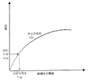
空調設備の流量が少なくなると水車1を通過する流量も小さくなる。これに伴い上流圧力センサー14aと下流圧力センサー14bの信号15が変化する。発電機コントローラ17は信号15の変化に対応して発電機回転速度が上昇するように発電機制御信号16aを発電機2に送る。発電機2の回転速度上昇により発電機2に直結されている水車1の回転速度が上昇すると羽根車内の流動状況が図5に示すようになる。水車を通過する水流は圧力エネルギーによる半径方向内向の力により羽根車内を外側から内側へ向かって流れている。このとき羽根車が回転するので水流も羽根車と一緒に回転する。回転する水流には羽根車の回転角速度ωにより遠心加速度rω2が作用する。即ち、羽根車内の水流には遠心加速度による半径方向外向の力と、圧力エネルギーによる半径方向内向の力が働いて、拮抗した状態になっている。したがって、羽根車の回転速度が上昇すると遠心加速度による半径方向外向の力が相対的に大きくなり、水車を通過する流量が減少する。この様なフランシス水車の特性を実験で調べた結果を図6に示す。水車回転速度が大きくなると有効落差がほぼ一定のまま流量が低下する。この様に発電機コントローラ17で発電機2の回転速度を制御することにより、水車の有効落差を一定にしたまま流量を調節することが出来る。したがって、空調負荷の変動により流量が変化した場合でも、水車入口の圧力を水車が定格流量で運転したときの水車入口圧力に対し、所定の比率幅以内に収まるように運転できるので、還水配管10の圧力を適正に保つことが出来る。流量制御できる範囲は無拘束流量まで可能であるが、無拘束流量付近では出力低下が急なため実際の制御範囲は最小流量までである。最小流量は羽根車の形状に依存しており、比速度と相関があるので、事前に流量制御範囲を検討することが出来る。
【0026】
第4実施例を説明する。図4は本実施例によるエネルギー回収装置を取付けた水蓄熱式空調設備である。蓄熱槽6から配管が送水ポンプ7に繋がっており、送水ポンプ7からの配管は空調機器9に繋がっている。空調機器9からの配管は還水配管10に繋がっている。還水配管10は上部にチャッキ弁12を介してサージタンク13に繋がっている。還水配管10の下部は蓄熱槽6に繋がっている。還水配管10の途中の蓄熱槽に戻る手前に落水防止弁11が設置されている。落水防止弁11の上流側から分岐配管4が設けられ蓄熱槽6へ繋がっている。分岐配管4には手動弁5が設けられている。また、分岐配管4に設けられた手動弁5の下流には遠心形羽根車を持つフランシス水車1が設置されている。フランシス水車1にはブラシレス永久磁石同期発電機2が直結されており、発電機2の回転速度を制御する発電機コントローラ17が発電機2と結線されてエネルギー回収装置100を構成している。フランシス水車1の上流には圧力センサー14a、下流には圧力センサー14bが設置されている。圧力センサー14の信号15は発電機コントローラ17に入力されている。発電機コントローラ17からは発電機制御信号16aが出力され、発電機2を制御している。また、エネルギー回収装置100の下流の配管4bは上流の配管4aよりも配管口径が小さくなっている。さらに、エネルギー回収装置100の下流の配管4bには制御弁3が設置されている。発電機コントローラ17には電力測定装置17aが内蔵されており、発電機の出力電力を常に計測している。そして、あらかじめ発電機コントローラ17に記録された設定値より計測値が小さくなると計測結果をアナログ信号16bとして制御弁コントローラ17bに出力する。制御弁コントローラ17bには図7に示すフランシス水車1の流量に対する出力特性が関数f1として記録されている。また、図8に示す弁開度に対する流量特性が関数f2として記録されている。制御弁コントローラ17bは出力電力のアナログ信号16bを入力し関数f1で運転出力Popに対応する運転流量Qopを計算し、次に、運転流量Qopから関数f2で目標弁開度Vopを計算する。そして、制御弁3の弁開度をVopに調節する。したがって、空調負荷の変動により流量が変化し、流量が図7に示す水車発電機の回転速度調整で対応できる水車制御範囲より小さくなった場合でも、水車発電機の回転速度調整を停止し制御弁3の弁開度を調節することで、水車入口の圧力を水車が定格流量で運転したときの水車入口圧力に対し、所定の比率幅以内に収まるように運転できるので、還水配管10の圧力を適正に保つことが出来る。したがって、流量制御範囲を拡大することが出来る。
【0027】
ここで、第4実施例では図7に示す流量に対する出力特性を関数f1として記録したが、本発明はこれに限定するものではなく流量に対する有効落差特性を関数f1として記録しても同様の作用を実現できることは言うまでもない。また、制御弁コントローラ17bと発電機コントローラ16を一体に構成してもよい。
【0028】
なお、上記落水防止弁は、還水配管の途中に設ける場合や還水配管の最終端付近、もしくは、還水配管から蓄熱槽に注ぎ込む位置に設けられる場合がある。従って、落水防止弁は設備によって適宜設けられるものである。しかしながら、その場合であっても本発明に基づく上述の実施例は実施可能である。
【0029】
以上説明したように、本発明の実施例によれば、落水防止弁付の水蓄熱式空調設備において、還水配管に設けられた落水防止弁の上流から蓄熱槽へ繋がる分岐配管を設け、前記分岐配管にエネルギー回収装置を取り付けるので、還水配管の水の持つ位置エネルギーは落水防止弁の抵抗に浪費されることがなく、エネルギー回収装置で前記還水配管の水の持つ位置エネルギーを回収することが出来る。なお、本発明において、水以外のブライン液を使用することも可能である。
【0030】
また、本発明の実施例によれば、分岐配管に設けたエネルギー回収装置の下流側に制御弁を設けているので、空調設備が停止した場合に還水配管内の水が分岐配管を通って落水するのを防止できる。
【0031】
また、本発明の実施例によれば、エネルギー回収装置は遠心形羽根車の水車発電機と、水車発電機の下流側に設けた制御弁と、電力計測装置を有する発電機コントローラと、水車発電機の入口・出口の圧力センサーと、流量に対する水車出力特性を表す関数及び流量に対する弁開度特性を表す関数を記録し、水車出力に対応した弁開度を計算できる機能を有した制御弁コントローラで構成されているので、空調設備の流量が減少した場合でも水車出力があらかじめ発電機コントローラに記録した設定値までは水車発電機の回転速度を調節することで、また、水車出力があらかじめ発電機コントローラに記録した設定値より小さくなった場合は、制御弁の弁開度を調節することで、エネルギー回収装置の入口の圧力を水車が定格流量で運転したときの水車入口圧力に対し、所定の比率幅以内に収まるように運転できるので、還水配管10の圧力を適正に保つことが出来る。したがって、空調設備の流量が減少した場合でも前記還水配管内が負圧になり空洞を生じて騒音・振動・腐食が発生することを防止できる。
【0032】
【発明の効果】
本発明により、落水防止弁付水蓄熱式等の空調設備においても水力エネルギーを回収でき、空調負荷の変動に伴う流量変化に対応できるエネルギー回収装置の運転方法を有し、また、エネルギー回収装置が故障した場合でも空調設備が正常動作するビルの未利用エネルギーを回収することができる空調設備を得ることができる。
【図面の簡単な説明】
【図1】第1実施例の空調設備の構成説明図。
【図2】第2実施例の空調設備の構成説明図。
【図3】第3実施例の空調設備の構成説明図。
【図4】第4実施例の空調設備の構成説明図。
【図5】第4実施例で使用する羽根車の水流状況を示す説明図。
【図6】第4実施例で使用するフランシス水車発電機の特性説明図。
【図7】第4実施例で使用するフランシス水車発電機の特性説明図。
【図8】第4実施例で使用する制御弁の特性説明図。
【図9】開放還水方式水蓄熱式空調設備を示す構成説明図。
【図10】満水還水方式水蓄熱式空調設備を示す構成説明図。
【図11】従来のエネルギー回収装置を示す構成説明図。
【符号の説明】
1 水車
2 発電機
3 制御弁
4 分岐配管
5 手動弁
6 蓄熱槽
7 送水ポンプ
8 吐出し弁
9 空調負荷
10 還水配管
11 落水防止弁
12 チャッキ弁
13 サージタンク
14 圧力センサー
15 圧力センサーの出力信号
16 発電機制御信号
17 発電機コントローラ
18 送水ポンプ起動・停止信号[0001]
BACKGROUND OF THE INVENTION
The present invention relates to a technique for providing a method for mounting an air conditioner and an energy recovery device.
[0002]
[Prior art]
As a general form of the water heat storage type air conditioner, as shown in FIG. 9, it has a heat storage tank 6, and water in the heat storage tank 6 is pumped with an air conditioning load (A.H. ) 9 is fed to the heat storage tank 6 through the
[0003]
[Patent Document 1]
Japanese Patent Laid-Open No. 63-297949 [0004]
[Problems to be solved by the invention]
On the other hand, with the recent increase in building height, water storage type air conditioning equipment is also applied to buildings of about 5 to 10 floors. In this case, since the actual lifting head exceeds 20 m, there is a problem in the open return water method that vibration and noise at the time of falling water increase. In order to prevent this, the water
[0005]
The water
[0006]
When the air-conditioning is stopped and the water supply from the
[0007]
On the other hand, when the energy recovery device is installed on the upstream side of the water
[0008]
In addition, in order to operate the air conditioning equipment with the energy recovery device attached to the upstream side of the water
[0009]
In addition, when the energy recovery device is installed on the upstream side of the water
[0010]
Furthermore, when the energy recovery device fails, the air conditioner cannot operate normally because the state is the same as when an obstacle is generated in the return water pipe.
[0011]
The present invention has been made in view of such a situation, and the purpose thereof is to recover hydraulic energy even in an air conditioning facility such as a water heat storage type with a waterfall prevention valve, and to cope with a flow rate change accompanying a change in air conditioning load. Provided is a method of operating an energy recovery device capable of recovering unused energy in a building in which the air conditioning facility operates normally even if the energy recovery device fails. There is.
[0012]
[Means for Solving the Problems]
In order to achieve the above object, an air conditioner of the present invention has a water tank such as a water heat storage tank, and feeds water from the water tank to an air conditioning load such as a heat source device or a fan coil by a pump and passes through the air conditioning load. In the air conditioning equipment in which the water is led to the water tank by a return water pipe and returns to the water tank through the water fall prevention valve provided in the return water pipe, the water is supplied from the return water pipe upstream of the water fall prevention valve. A branch pipe to the layer was provided, and an energy recovery device was attached in the middle of the branch pipe. Thereby, since the return water returns to the water tank through the branch pipe, the potential energy of the return water is not wasted due to the resistance of the water fall prevention valve. Therefore, the potential energy can be recovered by the energy recovery device attached in the middle of the branch pipe. In addition, even if the energy recovery device fails and the flow through the branch pipe decreases as an obstacle, it flows through the water fall prevention valve of the return pipe of the existing equipment, affecting the operation of the air conditioning equipment. There is nothing.
[0013]
The air conditioning system of the present invention has a water tank, and pumps the water from the water tank to an air conditioning load such as a heat source device or a fan coil, and the water passing through the air conditioning load is guided to the water tank by a return water pipe. In the air conditioning system that returns to the water tank through the water fall prevention valve provided in the return water pipe, a branch pipe from the return water pipe upstream of the water fall prevention valve to the water tank is provided, and the middle of the branch pipe An energy recovery device is attached, and a control valve is provided downstream of the energy recovery device. As a result, the return water returns to the water tank through the branch pipe, so that the potential energy of the return water is not wasted due to the resistance of the water fall prevention valve, and the energy recovery device attached in the middle of the branch pipe The potential energy of the return water can be recovered. Further, when the air conditioning equipment is stopped, the control valve can be closed to prevent the branch pipe from falling.
[0014]
In addition, the operation method of the energy recovery device for an air conditioning facility according to the present invention includes a water tank, pumps the water from the water tank to an air conditioning load such as a heat source machine or a fan coil, and returns the water that has passed through the air conditioning load. In an air-conditioning facility such as a water heat storage type that is led to the water tank by a water pipe and returns to the water tank through a water fall prevention valve provided in the return water pipe, the water return from the return water pipe upstream of the water fall prevention valve When a branch pipe to the water layer is installed, an energy recovery device is installed in the middle of the branch pipe, and the flow rate passing through the energy recovery device changes, the inlet pressure of the energy recovery device is rated for the energy recovery device. Operation control of the energy recovery device is performed so that the pressure is within a predetermined ratio with respect to the inlet pressure of the energy recovery device when operating at a flow rate. As a result, the pressure in the return water pipe is appropriately maintained, so that it is possible to prevent the inside of the return water pipe from becoming a negative pressure and generating a cavity to generate noise, vibration, and corrosion.
[0015]
The water tank has a water tank and pumps the water from the water tank to an air conditioning load such as a heat source unit or a fan coil, and the water passing through the air conditioning load is led to the water tank by a return water pipe. In an air conditioning facility such as a water heat storage type that returns to the water tank through a water fall prevention valve provided in the pipe, a branch pipe from the return water pipe upstream of the water fall prevention valve to the water tank is provided, and in the middle of the branch pipe An energy recovery device is attached, a control valve is provided downstream of the energy recovery device, and when the flow rate passing through the energy recovery device changes, the inlet pressure of the energy recovery device is set at the rated flow rate of the energy recovery device. The operating state of the energy recovery device and the control valve are adjusted so that they are within a predetermined ratio range with respect to the inlet pressure of the energy recovery device during operation. As a result, the pressure in the return water pipe is appropriately maintained during the operation of the air conditioning equipment, so that it is possible to prevent the return water pipe from becoming a negative pressure and creating a cavity to generate noise, vibration, and corrosion. . Further, when the air conditioning equipment is stopped, the control valve can be closed to prevent the return water piping from falling.
[0016]
The energy recovery device according to the present invention is composed of a water wheel having a centrifugal impeller, a brushless permanent magnet synchronous generator, and a generator controller for controlling the generator, so that the generator controller rotates the generator. By adjusting the speed, the rotational speed of the water turbine directly connected to the generator can be adjusted. Therefore, the characteristics of the water wheel having a centrifugal impeller, that is, the characteristic that the flow rate passing through the water wheel changes depending on the rotational speed can be utilized to cope with the change in the flow rate passing through the water wheel. Thereby, it is possible to prevent noise, vibration, and corrosion from occurring due to a negative pressure in the return water pipe and a cavity.
[0017]
Further, the energy recovery device according to the present invention has a control valve provided on the downstream side of the energy recovery device because the downstream port size of the energy recovery device is smaller than the upstream piping size of the energy recovery device. An inexpensive energy recovery device that can be reduced in size can be provided.
[0018]
DETAILED DESCRIPTION OF THE INVENTION
An embodiment of the present invention will be described.
Embodiments of the air conditioning equipment and energy recovery apparatus of the present invention will be described with reference to FIGS. FIG. 1 is an explanatory diagram of the configuration of the air conditioning equipment of the first embodiment. FIG. 2 is an explanatory diagram of the configuration of the air conditioning equipment of the second embodiment. FIG. 3 is a diagram illustrating the configuration of the air conditioning equipment of the third embodiment. FIG. 4 is a diagram illustrating the configuration of the air conditioning equipment of the fourth embodiment. FIG. 5 is an explanatory view showing the water flow situation of the impeller used in the fourth embodiment. FIG. 6 is an explanatory diagram of the characteristics of the Francis turbine generator used in the fourth embodiment. FIG. 7 is an explanatory diagram of the characteristics of the Francis turbine generator used in the fourth embodiment. FIG. 8 is a characteristic explanatory diagram of a control valve used in the fourth embodiment.
[0019]
A first embodiment will be described. FIG. 1 shows a water heat storage type air conditioner equipped with an energy recovery device according to this embodiment. The piping from the heat storage tank 6 is connected to the
[0020]
The water in the heat storage tank 6 is sent to the
[0021]
Further, the
[0022]
A second embodiment will be described. FIG. 2 shows a water heat storage type air conditioner equipped with an energy recovery device according to this embodiment. The piping from the heat storage tank 6 is connected to the
[0023]
Since the
[0024]
A third embodiment will be described. FIG. 3 shows a water heat storage type air conditioner equipped with an energy recovery device according to this embodiment. The piping from the heat storage tank 6 is connected to the
[0025]
When the flow rate of the air conditioning equipment decreases, the flow rate passing through the
[0026]
A fourth embodiment will be described. FIG. 4 shows a water heat storage type air conditioner equipped with an energy recovery device according to this embodiment. The piping from the heat storage tank 6 is connected to the
[0027]
Here, in the fourth embodiment, the output characteristic with respect to the flow rate shown in FIG. 7 is recorded as the function f1, but the present invention is not limited to this, and the same effect can be obtained even if the effective head characteristic with respect to the flow rate is recorded as the function f1. It goes without saying that can be realized. Further, the
[0028]
In addition, when the said water fall prevention valve is provided in the middle of return water piping, the final end of return water piping, or the position poured into a thermal storage tank from return water piping may be provided. Therefore, the water fall prevention valve is appropriately provided depending on the equipment. However, even in that case, the above-described embodiment according to the present invention can be implemented.
[0029]
As described above, according to the embodiment of the present invention, in the water heat storage type air conditioner with a water fall prevention valve, the branch pipe connected to the heat storage tank from the upstream of the water fall prevention valve provided in the return water pipe is provided, Since the energy recovery device is attached to the branch pipe, the potential energy of the water in the return water pipe is not wasted by the resistance of the water fall prevention valve, and the energy recovery device recovers the potential energy of the water in the return water pipe I can do it. In the present invention, it is also possible to use a brine solution other than water.
[0030]
Further, according to the embodiment of the present invention, since the control valve is provided on the downstream side of the energy recovery device provided in the branch pipe, the water in the return water pipe passes through the branch pipe when the air conditioning equipment is stopped. Can prevent water from falling.
[0031]
According to the embodiment of the present invention, the energy recovery device includes a centrifugal impeller water turbine generator, a control valve provided on the downstream side of the water turbine generator, a generator controller having a power measuring device, and a turbine power generation. Control valve controller with the function to record the valve opening corresponding to the turbine output by recording the pressure sensor at the inlet / outlet of the machine, the function expressing the turbine output characteristic with respect to the flow rate, and the function representing the valve opening characteristic with respect to the flow rate Therefore, even if the flow rate of the air conditioning equipment decreases, the turbine output can be adjusted in advance by adjusting the rotational speed of the turbine generator until the turbine output reaches the set value recorded in the generator controller in advance. When the set value recorded in the controller is smaller, the water turbine is operated at the rated flow rate by adjusting the valve opening of the control valve. To Kino waterwheel inlet pressure, so can be operated to fit within a predetermined ratio range, it is possible to maintain proper pressure of
[0032]
【The invention's effect】
According to the present invention, it is possible to recover hydraulic energy even in an air conditioning facility such as a water heat storage type with a water fall prevention valve, and to have an operation method of an energy recovery device that can cope with a flow rate change accompanying a change in air conditioning load. Even when a failure occurs, it is possible to obtain an air conditioning facility that can recover unused energy of a building in which the air conditioning facility operates normally.
[Brief description of the drawings]
FIG. 1 is a diagram illustrating the configuration of an air conditioning facility according to a first embodiment.
FIG. 2 is a diagram illustrating the configuration of an air conditioning facility according to a second embodiment.
FIG. 3 is a diagram illustrating the configuration of an air conditioning facility according to a third embodiment.
FIG. 4 is a diagram illustrating the configuration of an air conditioning facility according to a fourth embodiment.
FIG. 5 is an explanatory diagram showing a water flow situation of an impeller used in the fourth embodiment.
FIG. 6 is a characteristic explanatory diagram of a Francis turbine generator used in the fourth embodiment.
FIG. 7 is a characteristic explanatory diagram of a Francis turbine generator used in the fourth embodiment.
FIG. 8 is a characteristic explanatory diagram of a control valve used in the fourth embodiment.
FIG. 9 is a configuration explanatory view showing an open return water type water storage type air conditioning system.
FIG. 10 is a configuration explanatory view showing a full-water return water type water storage type air conditioner.
FIG. 11 is a configuration explanatory view showing a conventional energy recovery device.
[Explanation of symbols]
DESCRIPTION OF
Claims (8)
前記落水防止弁の上流側の還水配管に前記水槽へ分岐して導く分岐配管を接続し、該分岐配管の途中にエネルギー回収装置を取付けられているとともに、前記落水防止弁を通過するための水の抵抗は、前記空調負荷の高さにある水の有する位置エネルギーに相当する圧力ヘッドよりも大きく、前記圧力ヘッドと前記分岐配管から前記還水配管に還流してきた水の水圧を加えた水の抵抗を加えた値よりも小さいことを特徴とするエネルギー回収装置の取付方法。A water tank, a water supply pipe for supplying water from the water tank to an air conditioning load such as a heat source device or a fan coil by a pump, a return water pipe for guiding the water passing through the air conditioning load to the water tank, and the return water pipe are provided. In a method of attaching an energy recovery device to an air conditioner equipped with a water fall prevention valve,
A branch pipe that branches and leads to the water tank is connected to the return water pipe on the upstream side of the water fall prevention valve, and an energy recovery device is attached in the middle of the branch pipe to pass through the water fall prevention valve. The water resistance is larger than the pressure head corresponding to the potential energy of water at the height of the air conditioning load, and is water added with the water pressure returned to the return water pipe from the pressure head and the branch pipe. A method for mounting an energy recovery device, wherein the value is smaller than a value obtained by adding a resistance of .
前記落水防止弁の上流側の還水配管に接続して前記水槽へ分岐して導く分岐配管と、該分岐配管の途中に取付けたエネルギー回収装置とを有し、前記落水防止弁を通過するための水の抵抗は、前記空調負荷の高さにある水の有する位置エネルギーに相当する圧力ヘッドよりも大きく、前記圧力ヘッドと前記分岐配管から前記還水配管に還流してきた水の水圧を加えた水の抵抗を加えた値よりも小さいことを特徴とする空調設備。A water tank, a water supply pipe for supplying water from the water tank to an air conditioning load such as a heat source device or a fan coil by a pump, a return water pipe for guiding the water passing through the air conditioning load to the water tank, and the return water pipe are provided. In air conditioning equipment equipped with a water fall prevention valve,
Wherein a branch pipe connected to the upstream side of the Kaemizu pipe guiding branches to the water tank overboard valve, possess an energy recovery device attached to the middle of the branch pipe, for passing through the drainage valve The water resistance of the water is larger than the pressure head corresponding to the potential energy possessed by the water at the height of the air conditioning load, and the water pressure of the water returned from the pressure head and the branch pipe to the return water pipe is added. An air conditioner characterized by being smaller than the value added with water resistance .
Priority Applications (5)
| Application Number | Priority Date | Filing Date | Title |
|---|---|---|---|
| JP2003136161A JP4069010B2 (en) | 2003-05-14 | 2003-05-14 | Air conditioning equipment and energy recovery device mounting method |
| US10/808,625 US7296429B2 (en) | 2003-05-14 | 2004-03-24 | Air-conditioning system and method of installing energy recovery apparatus |
| EP04007271A EP1479980A1 (en) | 2003-05-14 | 2004-03-25 | Air-conditioning system and method of installing energy recovery apparatus |
| CNB2004100382229A CN100547308C (en) | 2003-05-14 | 2004-05-13 | Air conditioner and method for installing energy recovery device in air conditioner |
| US11/900,477 US7818973B2 (en) | 2003-05-14 | 2007-09-11 | Air-conditioning system and method of installing energy recovery apparatus |
Applications Claiming Priority (1)
| Application Number | Priority Date | Filing Date | Title |
|---|---|---|---|
| JP2003136161A JP4069010B2 (en) | 2003-05-14 | 2003-05-14 | Air conditioning equipment and energy recovery device mounting method |
Publications (2)
| Publication Number | Publication Date |
|---|---|
| JP2004340446A JP2004340446A (en) | 2004-12-02 |
| JP4069010B2 true JP4069010B2 (en) | 2008-03-26 |
Family
ID=33095365
Family Applications (1)
| Application Number | Title | Priority Date | Filing Date |
|---|---|---|---|
| JP2003136161A Expired - Lifetime JP4069010B2 (en) | 2003-05-14 | 2003-05-14 | Air conditioning equipment and energy recovery device mounting method |
Country Status (4)
| Country | Link |
|---|---|
| US (2) | US7296429B2 (en) |
| EP (1) | EP1479980A1 (en) |
| JP (1) | JP4069010B2 (en) |
| CN (1) | CN100547308C (en) |
Families Citing this family (15)
| Publication number | Priority date | Publication date | Assignee | Title |
|---|---|---|---|---|
| JP2006313059A (en) * | 2005-04-05 | 2006-11-16 | Univ Of Tokyo | Pseudo-enclosed cold / hot water circulation system and low-loss fluid transfer system for energy-saving air conditioning |
| JP4896623B2 (en) * | 2006-08-08 | 2012-03-14 | 高砂熱学工業株式会社 | Air conditioning system |
| CN101963124B (en) * | 2009-07-25 | 2012-09-19 | 汪健 | Electricity-generating and air conditioning all-in-one machine of ground source energy |
| US20120169061A1 (en) * | 2009-09-15 | 2012-07-05 | Tai Koan Lee | Power Generation System, Power Generator and Method Thereof |
| TW201300632A (en) * | 2011-06-24 | 2013-01-01 | Hon Hai Prec Ind Co Ltd | Hydroelectric generating device |
| US10180414B2 (en) | 2013-03-15 | 2019-01-15 | Mueller International, Llc | Systems for measuring properties of water in a water distribution system |
| US11041839B2 (en) | 2015-06-05 | 2021-06-22 | Mueller International, Llc | Distribution system monitoring |
| CN105909457A (en) * | 2016-06-16 | 2016-08-31 | 江苏心日源建筑节能科技股份有限公司 | Pressure difference bypass balance power generation device and central air conditioner water path system with device |
| KR101815539B1 (en) | 2016-06-30 | 2018-01-05 | (주)케이비테크놀로지 | Generator Using Drop of Waste Water in Building |
| CN110454313B (en) * | 2019-06-24 | 2024-08-13 | 水利部农村电气化研究所 | Utilize large-scale central air conditioning cooling water return water power generation facility |
| CN111730225A (en) * | 2020-04-24 | 2020-10-02 | 中国化学工程第三建设有限公司 | Large-scale recovery air conditioner assembly installation method |
| US11725366B2 (en) | 2020-07-16 | 2023-08-15 | Mueller International, Llc | Remote-operated flushing system |
| CN111964164A (en) * | 2020-08-21 | 2020-11-20 | 王丽丽 | High-efficient cooling system of outer machine of air conditioner for communication network computer lab |
| JP7743219B2 (en) * | 2021-07-16 | 2025-09-24 | 東洋熱工業株式会社 | Open piping system and pressure control method |
| KR102631083B1 (en) * | 2023-06-16 | 2024-01-30 | 주식회사 에너지컨설팅 | Regenerative heat pump system comprising geothermal exchanger |
Family Cites Families (7)
| Publication number | Priority date | Publication date | Assignee | Title |
|---|---|---|---|---|
| JPS5136748A (en) | 1974-09-24 | 1976-03-27 | Takasago Thermal Engineering | KUKICHOWASHISUTEMUYOEKITAIJUNKANSOCHI |
| JPS51140350A (en) | 1975-05-30 | 1976-12-03 | Hitachi Ltd | Liquid circulation and transportation apparatus |
| US4352025A (en) | 1980-11-17 | 1982-09-28 | Troyen Harry D | System for generation of electrical power |
| JPS63297949A (en) | 1987-05-28 | 1988-12-05 | Tokai Eng Kk | Recovering method for surplus energy in air conditioning equipment utilizing heat accumulating tank |
| US5497615A (en) * | 1994-03-21 | 1996-03-12 | Noe; James C. | Gas turbine generator set |
| JP2004003414A (en) | 2002-01-17 | 2004-01-08 | Hitachi Ltd | Energy recovery system and operating method thereof |
| EP1329672B1 (en) * | 2002-01-17 | 2006-10-11 | Hitachi, Ltd. | Energy collecting system and method of operating the same |
-
2003
- 2003-05-14 JP JP2003136161A patent/JP4069010B2/en not_active Expired - Lifetime
-
2004
- 2004-03-24 US US10/808,625 patent/US7296429B2/en not_active Expired - Fee Related
- 2004-03-25 EP EP04007271A patent/EP1479980A1/en not_active Withdrawn
- 2004-05-13 CN CNB2004100382229A patent/CN100547308C/en not_active Expired - Fee Related
-
2007
- 2007-09-11 US US11/900,477 patent/US7818973B2/en not_active Expired - Fee Related
Also Published As
| Publication number | Publication date |
|---|---|
| US20040237545A1 (en) | 2004-12-02 |
| US7296429B2 (en) | 2007-11-20 |
| EP1479980A1 (en) | 2004-11-24 |
| US20080022699A1 (en) | 2008-01-31 |
| US7818973B2 (en) | 2010-10-26 |
| CN100547308C (en) | 2009-10-07 |
| CN1550665A (en) | 2004-12-01 |
| JP2004340446A (en) | 2004-12-02 |
Similar Documents
| Publication | Publication Date | Title |
|---|---|---|
| JP4069010B2 (en) | Air conditioning equipment and energy recovery device mounting method | |
| CN103814261A (en) | Centrifugal compressor diffuser control | |
| JP2009108756A (en) | Hydraulic compressor equipment and operation method thereof | |
| JP6848470B2 (en) | Hydropower system | |
| CN111148897B (en) | Hydroelectric Power System | |
| US11118558B2 (en) | Hydroelectric power generation system | |
| JP2002242813A (en) | Power generation system | |
| CN108626054B (en) | Movable Blade Operating System of Hydraulic Machinery | |
| JP4673582B2 (en) | Operation control device and operation control method for pump turbine | |
| JP6733767B1 (en) | Hydroelectric system | |
| CN110088458A (en) | Flow controller | |
| JP4610866B2 (en) | Energy recovery system and control method, and multiple turbine generator system and operation control method | |
| JP2018050357A (en) | Hydropower system | |
| JPH07243304A (en) | Extraction pressure control method for extraction turbine | |
| KR101171894B1 (en) | System for controling active surge and stall for compressor | |
| JP2006063961A (en) | Turbo pump | |
| JP2001324083A (en) | Water hammer phenomenon preventing structure | |
| JP6805671B2 (en) | Hydropower system | |
| JP7843254B2 (en) | Hydraulic machinery and its control method | |
| JP2006316759A (en) | Compression device | |
| JP4589026B2 (en) | Pump device | |
| JP2001165024A (en) | Francis type hydraulic machine | |
| JPS6327204Y2 (en) | ||
| JPH0267467A (en) | Operating method for hydraulic machine | |
| JPS6139637B2 (en) |
Legal Events
| Date | Code | Title | Description |
|---|---|---|---|
| A621 | Written request for application examination |
Free format text: JAPANESE INTERMEDIATE CODE: A621 Effective date: 20050401 |
|
| A977 | Report on retrieval |
Free format text: JAPANESE INTERMEDIATE CODE: A971007 Effective date: 20070815 |
|
| A131 | Notification of reasons for refusal |
Free format text: JAPANESE INTERMEDIATE CODE: A131 Effective date: 20070828 |
|
| A521 | Request for written amendment filed |
Free format text: JAPANESE INTERMEDIATE CODE: A523 Effective date: 20071029 |
|
| TRDD | Decision of grant or rejection written | ||
| A01 | Written decision to grant a patent or to grant a registration (utility model) |
Free format text: JAPANESE INTERMEDIATE CODE: A01 Effective date: 20080108 |
|
| A61 | First payment of annual fees (during grant procedure) |
Free format text: JAPANESE INTERMEDIATE CODE: A61 Effective date: 20080111 |
|
| FPAY | Renewal fee payment (event date is renewal date of database) |
Free format text: PAYMENT UNTIL: 20110118 Year of fee payment: 3 |
|
| R150 | Certificate of patent or registration of utility model |
Free format text: JAPANESE INTERMEDIATE CODE: R150 Ref document number: 4069010 Country of ref document: JP Free format text: JAPANESE INTERMEDIATE CODE: R150 |
|
| FPAY | Renewal fee payment (event date is renewal date of database) |
Free format text: PAYMENT UNTIL: 20110118 Year of fee payment: 3 |
|
| FPAY | Renewal fee payment (event date is renewal date of database) |
Free format text: PAYMENT UNTIL: 20120118 Year of fee payment: 4 |
|
| FPAY | Renewal fee payment (event date is renewal date of database) |
Free format text: PAYMENT UNTIL: 20130118 Year of fee payment: 5 |
|
| EXPY | Cancellation because of completion of term |