JP3969069B2 - Wafer polishing equipment - Google Patents
Wafer polishing equipment Download PDFInfo
- Publication number
- JP3969069B2 JP3969069B2 JP2001357808A JP2001357808A JP3969069B2 JP 3969069 B2 JP3969069 B2 JP 3969069B2 JP 2001357808 A JP2001357808 A JP 2001357808A JP 2001357808 A JP2001357808 A JP 2001357808A JP 3969069 B2 JP3969069 B2 JP 3969069B2
- Authority
- JP
- Japan
- Prior art keywords
- retainer ring
- wafer
- ring
- protective sheet
- back plate
- Prior art date
- Legal status (The legal status is an assumption and is not a legal conclusion. Google has not performed a legal analysis and makes no representation as to the accuracy of the status listed.)
- Expired - Lifetime
Links
Images


Classifications
-
- B—PERFORMING OPERATIONS; TRANSPORTING
- B24—GRINDING; POLISHING
- B24B—MACHINES, DEVICES, OR PROCESSES FOR GRINDING OR POLISHING; DRESSING OR CONDITIONING OF ABRADING SURFACES; FEEDING OF GRINDING, POLISHING, OR LAPPING AGENTS
- B24B37/00—Lapping machines or devices; Accessories
- B24B37/27—Work carriers
- B24B37/30—Work carriers for single side lapping of plane surfaces
-
- H—ELECTRICITY
- H10—SEMICONDUCTOR DEVICES; ELECTRIC SOLID-STATE DEVICES NOT OTHERWISE PROVIDED FOR
- H10P—GENERIC PROCESSES OR APPARATUS FOR THE MANUFACTURE OR TREATMENT OF DEVICES COVERED BY CLASS H10
- H10P52/00—Grinding, lapping or polishing of wafers, substrates or parts of devices
Landscapes
- Engineering & Computer Science (AREA)
- Mechanical Engineering (AREA)
- Finish Polishing, Edge Sharpening, And Grinding By Specific Grinding Devices (AREA)
- Mechanical Treatment Of Semiconductor (AREA)
Description
【0001】
【発明の属する技術分野】
本発明は化学的機械研磨法(CMP:Chemical Mechanical Polishing )によってウェーハを研磨するウェーハ研磨装置に関する。
【0002】
【従来の技術】
CMPによるウェーハの研磨は、回転する研磨パッドにウェーハを回転させながら所定の圧力で押し付け、その研磨パッドとウェーハとの間にメカノケミカル研磨剤を供給することにより行われる。この際、ウェーハは、その周囲をリテーナーリングに包囲されるとともに、その裏面側をキャリア(バックプレート)に保持されて研磨パッドに押圧される。
【0003】
しかし、従来のウェーハ研磨装置では、ウェーハの裏面にキャリアの硬い面が直接接触してウェーハを押圧しているため、ウェーハの裏面に傷が付くという欠点があった。また、キャリアの面精度がウェーハの研磨面に転写されるので、この面の加工を高精度で行う必要があった。
【0004】
そこで、本願出願人は、このような欠点を解消すべく特願平11−128558号において、キャリア(バックプレート)の下部にリテーナーリングと一体の保護シートを設けたウェーハ研磨装置を提案した。このウェーハ研磨装置は、保護シートを介してエア層によりウェーハの裏面を押圧することにより、キャリアの硬い面がウェーハの裏面に直接接触するのを防止する。これにより、ウェーハの裏面に傷が付くのを防止している。また、キャリア(バックプレート)面の加工を高精度で行わなくてもすむようになった。
【0005】
この場合、保護シート1は、図6に示すように、キャリア2の周囲に配置されたリテーナーリングホルダ3に周縁部を接着して取り付けられ、リテーナーリング4は、その保護シート1の下部に接着によって取り付けられる。
【0006】
【発明が解決しようとする課題】
しかしながら、上記のように保護シート1とリテーナーリング4を取り付けると、リテーナーリング4の厚さをウェーハWの厚さ(1mm以下)と合わせなければならないため、きわめて薄くなり、リテーナーリング4の強度、耐久性が低下するという欠点があった。
【0007】
また、保護シート1は全体に皺なく均一に取り付けるのが好ましいが、上記の取り付け方法では皺なく取り付けることが難しいという欠点があった。
【0008】
一方、保護シート1の材質、厚さ等によっては、保護シート1を必ずしもリテーナーリング4に固定しなくても研磨できるという知見が得られた。
【0009】
本発明は、このような事情に鑑みてなされたもので、簡単に保護シートを取り付けることができ、リテーナーリングの強度、耐久性を確保できるウェーハ研磨装置を提供することを目的とする。
【0010】
【課題を解決するための手段】
本発明は前記目的を達成するために、流体層を介してウェーハを研磨パッドに押し付けて研磨するウェーハ研磨装置において、ウェーハ保持ヘッドにリテーナーリングを取り付けるとともに、該リテーナーリングの内側にシート材を配設し、該シート材を介してウェーハを研磨パッドに押し付けて研磨することを特徴とするウェーハ研磨装置を提供する。
【0011】
本発明によれば、シート材の材質、厚さ等によっては、リテーナーリングの内側に該シート材を配設するのみで済む。また、シート材を全体に皺なく均一に取り付ける場合にはリテーナーリングに取り付ければよい。いずれにしろ、これにより、簡単に保護シートを取り付けることができる効果が得られる。
【0012】
本発明において、前記リテーナーリングは、その上部に形成された嵌合部を前記ウェーハ保持ヘッドに設けられたホルダの下部に形成された被嵌合部に嵌合させて該ホルダに取り付けられ、前記シート材は、その周縁部が前記リテーナーリングの嵌合部と前記ホルダの被嵌合部との間に挟持されて張設されることが好ましい。
【0013】
この構成によれば、シート材は、その周縁部をリテーナーリングの嵌合部とホルダの被嵌合部との間に挟持されてリテーナーリングの内周部に張設される。このように張設することにより、シート材は、その周縁部が外周方向に引っ張られるため、全面に皺なく均一に張設することができる。
【0014】
【発明の実施の形態】
以下、添付図面に従って本発明に係るウェーハ研磨装置の好ましい実施の形態について詳説する。
【0015】
図1は、ウェーハ研磨装置10の全体構成を示す斜視図である。同図に示すようにウェーハ研磨装置10は、主として研磨定盤12とウェーハ保持ヘッド14とで構成されている。
【0016】
研磨定盤12は円盤状に形成され、その下面中央には回転軸16が連結されている。研磨定盤12は、この回転軸16に連結されたモータ18を駆動することにより回転する。また、この研磨定盤12の上面には研磨パッド20が貼り付けられており、この研磨パッド20上に図示しないノズルからメカノケミカル研磨剤(スラリー)が供給される。
【0017】
ウェーハ保持ヘッド14は、 図2に示すように、主としてヘッド本体22、バックプレート(キャリア)24、バックプレート押圧手段26、リテーナーリング28、 リテーナーリング押圧手段30等で構成されている。
【0018】
ヘッド本体22は円盤状に形成され、その上面中央には回転軸32が連結されている。ヘッド本体22は、この回転軸32に連結された図示しないモータに駆動されて回転する。
【0019】
バックプレート24は円盤状に形成され、ヘッド本体22の下部中央に配置されている。バックプレート24の上面中央部には円筒状の凹部34が形成されている。凹部34にはヘッド本体22の軸部36がピン38を介して嵌着されている。 バックプレート24は、このピン38を介してヘッド本体22から回転が伝達される。
【0020】
また、バックプレート24の上面周縁部にはバックプレート押圧部材40が設けられている。バックプレート24は、このバックプレート押圧部材40を介してバックプレート押圧手段26から押圧力が伝達される。
【0021】
また、バックプレート24の下面には、エアの吸引・吹出溝42が形成されている。この吸引・吹出溝42には、バックプレート24の内部に形成されたエア流路44が連通されている。エア流路44には図示しないエア配管を介して吸気ポンプと給気ポンプが接続されている。吸引・吹出溝42からのエアの吸引と吹出は、この吸気ポンプと給気ポンプとを切り替えることにより行われる。
【0022】
バックプレート押圧手段26は、 ヘッド本体22の下面外周部に配置され、 バックプレート押圧部材40に押圧力を与えることにより、これに結合されたバックプレート24に押圧力を伝達する。このバックプレート押圧手段26は、 好ましくはエアの吸排気により膨張収縮するゴムシート製のエアバッグ46で構成される。エアバッグ46にはエアを供給するための空気供給機構48が連結され、この空気供給機構48には、図示しないポンプから圧送されるエアの圧力を調整するレギュレータ(不図示)が具備される。
【0023】
リテーナーリング28は、リング状に形成され、バックプレート24の外周に配置される。このリテーナーリング28は、ホルダであるリテーナーリングホルダ50に取り付けられ、その内周部にはシート材である保護シート52が張設される。
【0024】
リテーナーリングホルダ50はリング状に形成され、図2及び図3に示すように、その下面には環状の凹部54が形成されている。一方、リテーナーリング28の上面には、この凹部54に嵌合する凸部56が形成されており、この凸部56をリテーナーリングホルダ50の凹部54に嵌合させることにより、リテーナーリング28がリテーナーリングホルダ50に装着される。
【0025】
保護シート52は、円形状に形成され、複数の貫通孔である孔52Aが開けられている。この保護シート52は、周縁部がリテーナーリング28とリテーナーリングホルダ50との間で挟持されることにより、リテーナーリング28の内側に張設される。すなわち、保護シート52は、薄い円盤状に形成されており、リテーナーリング28の取り付け時に、その周縁部をリテーナーリング28の凸部56とリテーナーリングホルダ50の凹部54との間に挟み込むことにより、リテーナーリング28の内側に張設される。このように張設することにより、保護シート52は取り付けと同時に外周方向に引っ張られ、全面に皺なく均一に張設される。
【0026】
なお、リテーナーリング28は、その凸部56をリテーナーリングホルダ50の凹部54に嵌合させた後、ボルト58、58、…でねじ止めすることにより、リテーナーリングホルダ50に固定される。このため、リテーナーリング28には、一定の間隔でねじ穴60、60、…が形成され、リテーナーリングホルダ50には一定の間隔で貫通穴62、62、…が形成されている。
【0027】
また、リテーナーリング28に形成された凸部56と、リテーナーリングホルダ50に形成された凹部54は、それぞれ内周側の壁面54A、56Aがテーパ状に形成されており、これにより嵌合作業が容易にできるようにされている。
【0028】
図2のごとく保護シート52が張設されたバックプレート24の下部には、保護シート52との間にエア層74が形成される。ウェーハWは、保護シート52とエア層74を介してバックプレート24に押圧される。バックプレート24の吸引・吹出溝42からエアを吹出し、同時にバックプレート24を押圧すると、エア層74の圧力が高くなり、バックプレート24を押圧する力とエア層74の圧力でバックプレート24を押し上げる力が同じになると、一定の圧力が維持される。
【0029】
また、保護シート52に形成された孔52Aは、ウェーハWを保持して搬送する際には吸着用の孔として作用し、研磨終了時には、 ウェーハWの剥離用のエア噴き出し孔として作用する。
【0030】
リテーナーリングホルダ50は、リング状に形成された取付部材64にスナップリング66を介して取り付けられている。スナップリング66は、リング状に形成され、その内周部には図3のごとく溝66Aが形成されている。このスナップリング66には切割りが形成されており、これにより拡縮可能に形成されている。リテーナーリングホルダ50と取付部材64は、その上端部外周と下端部外周に形成された外周フランジ部50A、64Aをスナップリング66に形成された溝66Aに嵌合させることにより、互いに一体化されて固定される。
【0031】
また、リテーナーリングホルダ50の内周部には内周フランジ部50Bが形成されており、この内周フランジ部50Bにバックプレート24の外周部に形成されたフランジ部24Aが遊嵌されている。上述の、バックプレート24を押圧する力とエア層74の圧力でバックプレート24を押し上げる力が同じ状態になるように、この遊嵌されている隙間より排出されるエア層74からのエアがコントロールされる。
【0032】
取付部材64には、図2のリテーナーリング押圧部材68が連結されている。リテーナーリング28は、このリテーナーリング押圧部材68を介してリテーナーリング押圧手段30からの押圧力が伝達される。
【0033】
リテーナーリング押圧手段30は、ヘッド本体22の下面の中央部に配置され、 リテーナーリング押圧部材68に押圧力を与えることで、 これに結合しているリテーナリング28を研磨パッド20に押し付ける。 このリテーナーリング押圧手段30も好ましくはバックプレート押圧手段26と同様にゴムシート製のエアバッグ70で構成される。エアバッグ70にはエアを供給するための空気供給機構72が連結され、この空気供給機構72には、図示しないポンプから圧送されるエアの圧力を調整するレギュレータ(不図示)が具備される。
【0034】
前記のごとく構成されたウェーハ研磨装置10のウェーハ研磨方法は次のとおりである。
【0035】
まず、ウェーハWをウェーハ保持ヘッド14で保持して研磨パッド20上に載置する。この際、ウェーハWはバックプレート24の下面に形成された吸引・吹出溝42からのエアを吸引して保持される。
【0036】
次に、バックプレート24の吸引・吹出溝42からエアを吹出し、同時にバックプレート24を押圧すると、エア層74の圧が高くなり、バックプレート24を押圧する力とエア層74の圧力でバックプレート24を押し上げる力が同じになると、一定の圧力が維持されるようになる。
【0037】
この状態で研磨定盤12を図1A方向に回転させるとともに、ウェーハ保持ヘッド14を図1B方向に回転させる。そして、その回転する研磨パッド20上に図示しないノズルからスラリーを供給する。これにより、ウェーハWの下面が研磨パッド20により研磨される。
【0038】
なお、保護シート52には複数の孔52Aが形成されているため(図3参照)、バックプレート24の吸引・吹出溝42から供給されたエアは、バックプレート24とウェーハW裏面との間で保護シート52を介してエア層74を形成し、ウェーハWを研磨パッド20に押圧する。
【0039】
また、ウェーハWを研磨パッド20に押圧する力は、保護シート52を介してエア層74で行うが、保護シート52がウェーハWを押圧している圧力と同じなので、保護シート52とウェーハWとの間にはエアの流れがほとんどなく、またエアの流れがあったとしても、エア量は非常に少ないので、スラリーの凝集が起らない。 また、保護シート52に厚さムラがあっても、ウェーハWの加工精度には影響を及ぼさない。
【0040】
次に、保護シート52の張設方法について説明する。
【0041】
まず、図5(a)に示すように、リテーナーリング28とリテーナーリングホルダ50とを分離する。そして、その分離されたリテーナーリング28とリテーナーリングホルダ50との間に保護シート52を配置する。
【0042】
次に、図5(b)に示すように、リテーナーリング28に形成された凸部56をリテーナーリングホルダ50に形成された凹部54に嵌め込む。これにより、保護シート52は、その周縁部がリテーナーリング28とリテーナーリングホルダ50との間に挟持されて、リテーナーリング28の内側に張設される。この際、保護シート52は外周方向に引っ張られながら挟持されるため、全面に皺なく均一に張設される。
【0043】
最後にリテーナーリング28をリテーナーリングホルダ50にボルト58、58、…で固定することにより、張設作業が終了する。
【0044】
このように、本実施の形態のウェーハ研磨装置10によれば、簡単に保護シート52をリテーナーリング28の内側に皺なく張設することができる。
【0045】
また、本実施の形態のウェーハ研磨装置10では、リテーナーリング28の上面に凸部56が形成されるため、リテーナーリングの強度、耐久性を向上させることができる。
【0046】
なお、本実施の形態では、保護シート52を挟持したリテーナーリング28とリテーナーリングホルダ50とをボルト58で固定しているが、接着剤で接着して固定してもよい。
【0047】
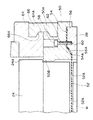
次に、図4により本発明に係るウェーハ研磨装置の他の好ましい実施の形態について説明する。なお、図2及び図3と同一、類似の部材については同様の符号を付し、その説明を省略する。
【0048】
リテーナーリング28は、リング状に形成され、バックプレート24の外周に配置される。このリテーナーリング28は、図3に示される構成のようにリテーナーリングホルダ50に取り付けられず、一体物で構成される。また、その内周部にシート材である保護シート52が張設されない。さらに、リテーナーリング28の内周部の下端には内周側に張り出したフランジ部28Aが形成されている。
【0049】
保護シート52は、円形状に形成され、複数の貫通孔である孔52Aが開けられている。この保護シート52は、その周縁部がリテーナーリング28の内側に配されるリング状部材52Bに張設されており、リング状部材52Bはリテーナーリング28に対し遊動状態にある。また、リング状部材52Bがリテーナーリング28と係合することによりウェーハ保持ヘッド14からの脱落防止がなされている。
【0050】
すなわち、保護シート52の板厚、材質等によっては、保護シート52が必ずしもリテーナーリング28に固定されなくても、保護シート52の周縁部がリング状部材52Bに張設されていれば、保護シート52が皺になったり、変形したりすることもなく、研磨作業には支障とならない。
【0051】
なお、リング状部材52Bの材質、厚さ、保護シート52の固定(張設)方法等は、保護シート52の材質、厚さ等を考慮し最適な条件を選択すればよい。また、リング状部材52Bを使用せず、保護シート52の周縁部を熱変形等させて周縁部の肉厚を大とし、実質的にリング状部材52Bを設けた構成と同様の機能を与えてもよい。
【0052】
リング状部材52Bは、ウェーハ保持ヘッド14が上昇した際には、リテーナーリング28の内周部下端のフランジ部28Aの上に載ることによりリテーナーリング28と係合し、脱落防止がなされる。なお、保護シート52の交換頻度が多い等の場合であって、リング状部材52Bのウェーハ保持ヘッド14からの脱落防止が不要な場合には、リテーナーリング28に上記のフランジ部28Aを設けない構成とすればよい。
【0053】
図4の構成では、バックプレート24の下面24Bが凹形状になっている。本発明は、既述のように、流体層を介してウェーハを研磨パッドに押し付けて研磨する方式を採用するので、バックプレート24の下面24Bの加工精度には基本的に影響されない。したがって、通常の研磨装置のウェーハ保持ヘッドと比べ、下面24Bの加工状態が多少悪くても、また、凹形状でなくても、良好な研磨結果が得られる。
【0054】
ただし、この場合であっても、バックプレート24の下面24Bを凹形状とすることにより、以下の効果が得られる。すなわち、ウェーハWを保持して搬送する際には、吸引・吹出溝42を使用してウェーハを吸着する。その際、下面24Bが凹形状以外の形状、たとえば、凸形状または凹凸が入り混じった形状であるならば、ウェーハWがその形状に倣わない限り良好な吸着とならない。
【0055】
一方、下面24Bが凹形状であれば、凹部が空洞部を形成し、ウェーハWがその形状に倣い良好な吸着状態となる。凹部の形状(凹部の深さ、断面形状:円弧状、放物線状、等)は、ウェーハ保持ヘッド14の構成、ウェーハWのサイズ等を考慮して最適化すればよい。
【0056】
リテーナーリング28は、リング状に形成された取付部材64にスナップリング80を介して取り付けられている。スナップリング80は、金属製の(非金属製でも可)単なるリング状部材であり、図3のごとく溝66Aは形成されていない。リテーナーリング28と取付部材64は、その外周部をスナップリング80により、互いに一体化されて固定される。このような構成であっても、リテーナーリング28と取付部材64との固定はでき、構成が容易になる。
【0057】
取付部材64には、図2のリテーナーリング押圧部材68が連結されている。リテーナーリング28は、このリテーナーリング押圧部材68を介してリテーナーリング押圧手段30からの押圧力が伝達される。
【0058】
以上に説明した構成は、本発明の実施例であるが、本発明の構成はこれらに限定されるものではなく、各種の構成が採り得る。
【0059】
たとえば、これまでの説明では、流体層として空気層(エア層)を介してウェーハWを研磨パッド20に押し付けて研磨する構成について述べてきたが、これに限られず窒素ガス等の他の気体、又は、水等の液体の層を介してウェーハWを研磨パッド20に押し付けることでもよい。
【0060】
水等の液体を使用する場合には、流量が多いとメカノケミカル研磨剤(スラリー)が希釈されるので好ましくないが、流量がわずかであって、かつ、純水等を使用するのであれば、メカノケミカル研磨剤の希釈、汚染等の大きな問題とはならず、適用できる。
【0061】
【発明の効果】
以上説明したように、本発明によれば、シート材の材質、厚さ等によっては、リテーナーリングの内側に該シート材を配設するのみで済む。また、シート材を全体に皺なく均一に取り付ける必要がある場合にはリテーナーリングに取り付ければよい。いずれにしろ、これにより、簡単に保護シートを取り付けることができる効果が得られる。
【0062】
また、本発明によれば、シート材の周縁部をリテーナーリングの嵌合部とホルダの被嵌合部との間で挟持することにより、簡単にシート材をムラなく張設することができる。また、リテーナーリングに嵌合部を凸状に形成することにより、リテーナーリング自体の強度、耐久性を向上させることができる。
【図面の簡単な説明】
【図1】ウェーハ研磨装置の全体構造を示す斜視図
【図2】ウェーハ保持ヘッドの構成を示す縦断面図
【図3】保護シートの挟持部の構成を示す断面図
【図4】保護シートの挟持部の他の構成を示す断面図
【図5】リテーナーリングの取付方法の説明図
【図6】従来のウェーハ保持ヘッドの要部の構成を示す正面図
【符号の説明】
10…ウェーハ研磨装置、12…研磨定盤、14…ウェーハ保持ヘッド、20…研磨パッド、22…ヘッド本体、24…バックプレート、28…リテーナーリング、34…凹部、50…リテーナーリングホルダ、52…保護シート(シート材)、52A…孔、54…凹部、54A…壁面、56…凸部、56A…壁面、74…エア層[0001]
BACKGROUND OF THE INVENTION
The present invention relates to a wafer polishing apparatus that polishes a wafer by chemical mechanical polishing (CMP).
[0002]
[Prior art]
Polishing of a wafer by CMP is performed by pressing the wafer against a rotating polishing pad with a predetermined pressure while rotating the wafer, and supplying a mechanochemical abrasive between the polishing pad and the wafer. At this time, the periphery of the wafer is surrounded by a retainer ring, and the back side thereof is held by the carrier (back plate) and pressed against the polishing pad.
[0003]
However, the conventional wafer polishing apparatus has a drawback that the back surface of the wafer is scratched because the hard surface of the carrier directly contacts the back surface of the wafer and presses the wafer. Further, since the surface accuracy of the carrier is transferred to the polished surface of the wafer, it is necessary to process this surface with high accuracy.
[0004]
Therefore, the applicant of the present application has proposed a wafer polishing apparatus in which a protective sheet integrated with a retainer ring is provided at the lower part of a carrier (back plate) in Japanese Patent Application No. 11-128558 in order to eliminate such drawbacks. This wafer polishing apparatus prevents the hard surface of the carrier from coming into direct contact with the back surface of the wafer by pressing the back surface of the wafer with an air layer through a protective sheet. This prevents the back surface of the wafer from being scratched. Further, it is not necessary to process the carrier (back plate) surface with high accuracy.
[0005]
In this case, as shown in FIG. 6, the protective sheet 1 is attached to the
[0006]
[Problems to be solved by the invention]
However, when the protective sheet 1 and the
[0007]
Moreover, although it is preferable to attach the protective sheet 1 uniformly throughout the entire surface, there is a drawback that it is difficult to attach the protective sheet 1 without using the above attachment method.
[0008]
On the other hand, depending on the material, thickness, etc. of the protective sheet 1, it was found that the protective sheet 1 can be polished without necessarily being fixed to the
[0009]
The present invention has been made in view of such circumstances, and an object of the present invention is to provide a wafer polishing apparatus in which a protective sheet can be easily attached and the strength and durability of the retainer ring can be secured.
[0010]
[Means for Solving the Problems]
In order to achieve the above object, according to the present invention, in a wafer polishing apparatus for polishing by pressing a wafer against a polishing pad through a fluid layer, a retainer ring is attached to a wafer holding head, and a sheet material is disposed inside the retainer ring. A wafer polishing apparatus is provided that polishes by pressing a wafer against a polishing pad through the sheet material.
[0011]
According to the present invention, depending on the material, thickness and the like of the sheet material, it is only necessary to dispose the sheet material inside the retainer ring. Moreover, what is necessary is just to attach to a retainer ring, when attaching a sheet | seat material uniformly over the whole. In any case, this provides an effect that the protective sheet can be easily attached.
[0012]
In the present invention, the retainer ring is attached to the holder by fitting a fitting portion formed at an upper portion thereof to a fitting portion formed at a lower portion of a holder provided in the wafer holding head, It is preferable that the sheet material is stretched while the peripheral edge portion is sandwiched between the fitting portion of the retainer ring and the fitted portion of the holder.
[0013]
According to this configuration, the peripheral edge portion of the sheet material is sandwiched between the fitting portion of the retainer ring and the fitted portion of the holder, and is stretched on the inner peripheral portion of the retainer ring. By stretching in this way, the peripheral edge of the sheet material is pulled in the outer circumferential direction, so that it can be stretched uniformly over the entire surface.
[0014]
DETAILED DESCRIPTION OF THE INVENTION
Hereinafter, preferred embodiments of a wafer polishing apparatus according to the present invention will be described in detail with reference to the accompanying drawings.
[0015]
FIG. 1 is a perspective view showing the overall configuration of the
[0016]
The
[0017]
As shown in FIG. 2, the
[0018]
The
[0019]
The
[0020]
Further, a back
[0021]
An air suction /
[0022]
The back plate pressing means 26 is disposed on the outer periphery of the lower surface of the head
[0023]
The
[0024]
The
[0025]
The
[0026]
The
[0027]
Further, the
[0028]
As shown in FIG. 2, an
[0029]
The
[0030]
The
[0031]
An inner
[0032]
The retainer
[0033]
The retainer ring pressing means 30 is disposed at the center of the lower surface of the
[0034]
The wafer polishing method of the
[0035]
First, the wafer W is held by the
[0036]
Next, when air is blown out from the suction /
[0037]
In this state, the polishing
[0038]
Since the
[0039]
Further, the force that presses the wafer W against the
[0040]
Next, a method for stretching the
[0041]
First, as shown in FIG. 5A, the
[0042]
Next, as shown in FIG. 5B, the
[0043]
Finally, the
[0044]
As described above, according to the
[0045]
Further, in the
[0046]
In this embodiment, the
[0047]
Next, another preferred embodiment of the wafer polishing apparatus according to the present invention will be described with reference to FIG. In addition, the same code | symbol is attached | subjected about the same and similar member as FIG.2 and FIG.3, and the description is abbreviate | omitted.
[0048]
The
[0049]
The
[0050]
That is, depending on the thickness, material, etc. of the
[0051]
The material and thickness of the ring-shaped
[0052]
When the
[0053]
In the configuration of FIG. 4, the
[0054]
However, even in this case, the following effects can be obtained by making the
[0055]
On the other hand, if the
[0056]
The
[0057]
The retainer
[0058]
The configuration described above is an example of the present invention, but the configuration of the present invention is not limited to these, and various configurations can be adopted.
[0059]
For example, in the description so far, the configuration in which the wafer W is pressed against the
[0060]
When using a liquid such as water, if the flow rate is large, the mechanochemical abrasive (slurry) is diluted, which is not preferable, but if the flow rate is small and pure water or the like is used, It is not a major problem such as dilution and contamination of mechanochemical abrasives and can be applied.
[0061]
【The invention's effect】
As described above, according to the present invention, depending on the material, thickness and the like of the sheet material, it is only necessary to dispose the sheet material inside the retainer ring. In addition, if it is necessary to attach the sheet material uniformly without any problem, it may be attached to the retainer ring. In any case, this provides an effect that the protective sheet can be easily attached.
[0062]
Further, according to the present invention, the sheet material can be easily stretched evenly by sandwiching the peripheral edge portion of the sheet material between the fitting portion of the retainer ring and the fitted portion of the holder. Moreover, the strength and durability of the retainer ring itself can be improved by forming the fitting portion in a convex shape on the retainer ring.
[Brief description of the drawings]
FIG. 1 is a perspective view showing the overall structure of a wafer polishing apparatus. FIG. 2 is a longitudinal sectional view showing the structure of a wafer holding head. FIG. 3 is a sectional view showing the structure of a holding portion of a protective sheet. FIG. 5 is an explanatory view of a retainer ring mounting method. FIG. 6 is a front view showing the structure of a main part of a conventional wafer holding head.
DESCRIPTION OF
Claims (1)
前記シート材は、その周縁部が前記リテーナーリングの内側に配されるリング状部材に張設されており、該リング状部材はリテーナーリングに対し遊動状態にあるとともに、前記リング状部材が前記リテーナーリングと係合することによりウェーハ保持ヘッドからの脱落防止がなされていることを特徴とするウェーハ研磨装置。In a wafer polishing apparatus for attaching a retainer ring to a wafer holding head, disposing a sheet material inside the retainer ring, and pressing and polishing the wafer against a polishing pad via a fluid layer that is a layer of air or water.
The sheet material is stretched around a ring-shaped member whose peripheral portion is arranged inside the retainer ring, the ring-shaped member is in a loose state with respect to the retainer ring, and the ring-shaped member is the retainer A wafer polishing apparatus characterized by being prevented from falling off from a wafer holding head by engaging with a ring.
Priority Applications (4)
| Application Number | Priority Date | Filing Date | Title |
|---|---|---|---|
| JP2001357808A JP3969069B2 (en) | 2000-12-04 | 2001-11-22 | Wafer polishing equipment |
| PCT/JP2001/010566 WO2002047140A1 (en) | 2000-12-04 | 2001-12-04 | Wafer polisher |
| US10/433,364 US7056196B2 (en) | 2000-12-04 | 2001-12-04 | Wafer polisher |
| KR1020037007211A KR100834930B1 (en) | 2000-12-04 | 2001-12-04 | Wafer Polishing Machine |
Applications Claiming Priority (3)
| Application Number | Priority Date | Filing Date | Title |
|---|---|---|---|
| JP2000-368638 | 2000-12-04 | ||
| JP2000368638 | 2000-12-04 | ||
| JP2001357808A JP3969069B2 (en) | 2000-12-04 | 2001-11-22 | Wafer polishing equipment |
Publications (2)
| Publication Number | Publication Date |
|---|---|
| JP2002233951A JP2002233951A (en) | 2002-08-20 |
| JP3969069B2 true JP3969069B2 (en) | 2007-08-29 |
Family
ID=26605187
Family Applications (1)
| Application Number | Title | Priority Date | Filing Date |
|---|---|---|---|
| JP2001357808A Expired - Lifetime JP3969069B2 (en) | 2000-12-04 | 2001-11-22 | Wafer polishing equipment |
Country Status (4)
| Country | Link |
|---|---|
| US (1) | US7056196B2 (en) |
| JP (1) | JP3969069B2 (en) |
| KR (1) | KR100834930B1 (en) |
| WO (1) | WO2002047140A1 (en) |
Families Citing this family (6)
| Publication number | Priority date | Publication date | Assignee | Title |
|---|---|---|---|---|
| JP4583207B2 (en) * | 2004-03-31 | 2010-11-17 | 不二越機械工業株式会社 | Polishing equipment |
| JP2008173741A (en) * | 2007-01-22 | 2008-07-31 | Elpida Memory Inc | Polishing device |
| JP5392483B2 (en) * | 2009-08-31 | 2014-01-22 | 不二越機械工業株式会社 | Polishing equipment |
| CN103619538A (en) * | 2011-06-29 | 2014-03-05 | 信越半导体株式会社 | Grinding head and grinding device |
| JP5821883B2 (en) * | 2013-03-22 | 2015-11-24 | 信越半導体株式会社 | Template assembly and method for manufacturing template assembly |
| US20230129597A1 (en) * | 2021-10-27 | 2023-04-27 | Sch Power Tech Co., Ltd. | Retaining Ring for Wafer Polishing |
Family Cites Families (15)
| Publication number | Priority date | Publication date | Assignee | Title |
|---|---|---|---|---|
| JP3218572B2 (en) * | 1992-07-01 | 2001-10-15 | 不二越機械工業株式会社 | Polishing plate for wafer pressing |
| US5651724A (en) * | 1994-09-08 | 1997-07-29 | Ebara Corporation | Method and apparatus for polishing workpiece |
| JPH1044000A (en) | 1996-08-08 | 1998-02-17 | Sony Corp | Wafer polishing apparatus and wafer polishing method |
| JPH10270398A (en) * | 1997-03-27 | 1998-10-09 | Fujikoshi Mach Corp | Wafer polishing device |
| US5964653A (en) * | 1997-07-11 | 1999-10-12 | Applied Materials, Inc. | Carrier head with a flexible membrane for a chemical mechanical polishing system |
| JPH11285966A (en) * | 1998-04-02 | 1999-10-19 | Speedfam-Ipec Co Ltd | Carrier and CMP equipment |
| US6162116A (en) * | 1999-01-23 | 2000-12-19 | Applied Materials, Inc. | Carrier head for chemical mechanical polishing |
| US6527624B1 (en) * | 1999-03-26 | 2003-03-04 | Applied Materials, Inc. | Carrier head for providing a polishing slurry |
| JP3085948B1 (en) * | 1999-05-10 | 2000-09-11 | 株式会社東京精密 | Wafer polishing equipment |
| US6358121B1 (en) * | 1999-07-09 | 2002-03-19 | Applied Materials, Inc. | Carrier head with a flexible membrane and an edge load ring |
| US6494774B1 (en) * | 1999-07-09 | 2002-12-17 | Applied Materials, Inc. | Carrier head with pressure transfer mechanism |
| US6663466B2 (en) * | 1999-11-17 | 2003-12-16 | Applied Materials, Inc. | Carrier head with a substrate detector |
| US6722965B2 (en) * | 2000-07-11 | 2004-04-20 | Applied Materials Inc. | Carrier head with flexible membranes to provide controllable pressure and loading area |
| US6540590B1 (en) * | 2000-08-31 | 2003-04-01 | Multi-Planar Technologies, Inc. | Chemical mechanical polishing apparatus and method having a rotating retaining ring |
| US6641461B2 (en) * | 2001-03-28 | 2003-11-04 | Multi Planar Technologyies, Inc. | Chemical mechanical polishing apparatus having edge, center and annular zone control of material removal |
-
2001
- 2001-11-22 JP JP2001357808A patent/JP3969069B2/en not_active Expired - Lifetime
- 2001-12-04 KR KR1020037007211A patent/KR100834930B1/en not_active Expired - Fee Related
- 2001-12-04 US US10/433,364 patent/US7056196B2/en not_active Expired - Fee Related
- 2001-12-04 WO PCT/JP2001/010566 patent/WO2002047140A1/en not_active Ceased
Also Published As
| Publication number | Publication date |
|---|---|
| KR100834930B1 (en) | 2008-06-04 |
| JP2002233951A (en) | 2002-08-20 |
| KR20030062362A (en) | 2003-07-23 |
| US7056196B2 (en) | 2006-06-06 |
| US20040018806A1 (en) | 2004-01-29 |
| WO2002047140A1 (en) | 2002-06-13 |
Similar Documents
| Publication | Publication Date | Title |
|---|---|---|
| US6450868B1 (en) | Carrier head with multi-part flexible membrane | |
| US6361419B1 (en) | Carrier head with controllable edge pressure | |
| JP4223682B2 (en) | Carrier head with detachable retainer ring for chemical mechanical polishing apparatus | |
| US5851140A (en) | Semiconductor wafer polishing apparatus with a flexible carrier plate | |
| JP3439970B2 (en) | Support head with flexible membrane for chemical mechanical polishing system | |
| US6494774B1 (en) | Carrier head with pressure transfer mechanism | |
| KR20010042314A (en) | Chemical mechanical polishing conditioner | |
| KR20020018641A (en) | Semiconductor wafer polishing apparatus with a variable polishing force wafer carrier head | |
| KR100440627B1 (en) | Structure of polishing head of polishing apparatus | |
| JP3969069B2 (en) | Wafer polishing equipment | |
| JP2003151933A (en) | Wafer polishing equipment | |
| JP3218572B2 (en) | Polishing plate for wafer pressing | |
| US6729946B2 (en) | Polishing apparatus | |
| JP2005011999A (en) | Workpiece holding head and polishing apparatus having the same | |
| US6656026B2 (en) | Wafer polishing apparatus | |
| US6435955B2 (en) | Abrasive machine | |
| JP2001121413A (en) | Method of holding planar workpiece | |
| TW202233359A (en) | Polishing head and polishing apparatus | |
| JP2005019440A (en) | Work holding head and polishing device having the same | |
| JP2003151931A (en) | Wafer-polishing apparatus | |
| JP2003124169A (en) | Wafer polishing device | |
| JP2007266299A (en) | Wafer-polishing apparatus and method | |
| JP2003124168A (en) | Wafer polishing device | |
| JP2003179014A (en) | Wafer polishing apparatus | |
| JP2005088171A (en) | Work holding head and polishing device having work holding head |
Legal Events
| Date | Code | Title | Description |
|---|---|---|---|
| A621 | Written request for application examination |
Free format text: JAPANESE INTERMEDIATE CODE: A621 Effective date: 20040416 |
|
| A131 | Notification of reasons for refusal |
Free format text: JAPANESE INTERMEDIATE CODE: A131 Effective date: 20061031 |
|
| A521 | Request for written amendment filed |
Free format text: JAPANESE INTERMEDIATE CODE: A523 Effective date: 20061227 |
|
| A131 | Notification of reasons for refusal |
Free format text: JAPANESE INTERMEDIATE CODE: A131 Effective date: 20070223 |
|
| A521 | Request for written amendment filed |
Free format text: JAPANESE INTERMEDIATE CODE: A523 Effective date: 20070418 |
|
| TRDD | Decision of grant or rejection written | ||
| A01 | Written decision to grant a patent or to grant a registration (utility model) |
Free format text: JAPANESE INTERMEDIATE CODE: A01 Effective date: 20070515 |
|
| A61 | First payment of annual fees (during grant procedure) |
Free format text: JAPANESE INTERMEDIATE CODE: A61 Effective date: 20070528 |
|
| R150 | Certificate of patent or registration of utility model |
Free format text: JAPANESE INTERMEDIATE CODE: R150 Ref document number: 3969069 Country of ref document: JP Free format text: JAPANESE INTERMEDIATE CODE: R150 |
|
| FPAY | Renewal fee payment (event date is renewal date of database) |
Free format text: PAYMENT UNTIL: 20100615 Year of fee payment: 3 |
|
| FPAY | Renewal fee payment (event date is renewal date of database) |
Free format text: PAYMENT UNTIL: 20110615 Year of fee payment: 4 |
|
| R250 | Receipt of annual fees |
Free format text: JAPANESE INTERMEDIATE CODE: R250 |
|
| FPAY | Renewal fee payment (event date is renewal date of database) |
Free format text: PAYMENT UNTIL: 20110615 Year of fee payment: 4 |
|
| FPAY | Renewal fee payment (event date is renewal date of database) |
Free format text: PAYMENT UNTIL: 20120615 Year of fee payment: 5 |
|
| R250 | Receipt of annual fees |
Free format text: JAPANESE INTERMEDIATE CODE: R250 |
|
| FPAY | Renewal fee payment (event date is renewal date of database) |
Free format text: PAYMENT UNTIL: 20120615 Year of fee payment: 5 |
|
| FPAY | Renewal fee payment (event date is renewal date of database) |
Free format text: PAYMENT UNTIL: 20130615 Year of fee payment: 6 |
|
| R250 | Receipt of annual fees |
Free format text: JAPANESE INTERMEDIATE CODE: R250 |
|
| R250 | Receipt of annual fees |
Free format text: JAPANESE INTERMEDIATE CODE: R250 |
|
| R250 | Receipt of annual fees |
Free format text: JAPANESE INTERMEDIATE CODE: R250 |
|
| R250 | Receipt of annual fees |
Free format text: JAPANESE INTERMEDIATE CODE: R250 |
|
| R250 | Receipt of annual fees |
Free format text: JAPANESE INTERMEDIATE CODE: R250 |
|
| R250 | Receipt of annual fees |
Free format text: JAPANESE INTERMEDIATE CODE: R250 |
|
| R250 | Receipt of annual fees |
Free format text: JAPANESE INTERMEDIATE CODE: R250 |
|
| R250 | Receipt of annual fees |
Free format text: JAPANESE INTERMEDIATE CODE: R250 |
|
| R250 | Receipt of annual fees |
Free format text: JAPANESE INTERMEDIATE CODE: R250 |
|
| R250 | Receipt of annual fees |
Free format text: JAPANESE INTERMEDIATE CODE: R250 |
|
| EXPY | Cancellation because of completion of term |