JP2007266299A - Wafer-polishing apparatus and method - Google Patents
Wafer-polishing apparatus and method Download PDFInfo
- Publication number
- JP2007266299A JP2007266299A JP2006089270A JP2006089270A JP2007266299A JP 2007266299 A JP2007266299 A JP 2007266299A JP 2006089270 A JP2006089270 A JP 2006089270A JP 2006089270 A JP2006089270 A JP 2006089270A JP 2007266299 A JP2007266299 A JP 2007266299A
- Authority
- JP
- Japan
- Prior art keywords
- wafer
- pressing
- carrier
- elastic member
- polishing
- Prior art date
- Legal status (The legal status is an assumption and is not a legal conclusion. Google has not performed a legal analysis and makes no representation as to the accuracy of the status listed.)
- Pending
Links
- 238000005498 polishing Methods 0.000 title claims abstract description 65
- 238000000034 method Methods 0.000 title claims abstract description 13
- 230000002093 peripheral effect Effects 0.000 claims description 28
- 229920000459 Nitrile rubber Polymers 0.000 claims description 5
- 229920000181 Ethylene propylene rubber Polymers 0.000 claims description 3
- 229920006311 Urethane elastomer Polymers 0.000 claims description 3
- 229920002379 silicone rubber Polymers 0.000 claims description 3
- 229920001971 elastomer Polymers 0.000 abstract description 40
- 230000001681 protective effect Effects 0.000 description 19
- 239000000463 material Substances 0.000 description 6
- XLYOFNOQVPJJNP-UHFFFAOYSA-N water Substances O XLYOFNOQVPJJNP-UHFFFAOYSA-N 0.000 description 6
- 238000007664 blowing Methods 0.000 description 5
- 239000012530 fluid Substances 0.000 description 5
- 230000007423 decrease Effects 0.000 description 3
- 230000000670 limiting effect Effects 0.000 description 3
- 229920002943 EPDM rubber Polymers 0.000 description 2
- 230000036961 partial effect Effects 0.000 description 2
- 229920001084 poly(chloroprene) Polymers 0.000 description 2
- 239000011347 resin Substances 0.000 description 2
- 229920005989 resin Polymers 0.000 description 2
- 239000002002 slurry Substances 0.000 description 2
- 230000002411 adverse Effects 0.000 description 1
- 230000001276 controlling effect Effects 0.000 description 1
- 230000003247 decreasing effect Effects 0.000 description 1
- 230000007547 defect Effects 0.000 description 1
- 235000012489 doughnuts Nutrition 0.000 description 1
- 230000000694 effects Effects 0.000 description 1
- 230000003631 expected effect Effects 0.000 description 1
- 230000001105 regulatory effect Effects 0.000 description 1
- 230000000717 retained effect Effects 0.000 description 1
- 239000000126 substance Substances 0.000 description 1
Images


Landscapes
- Finish Polishing, Edge Sharpening, And Grinding By Specific Grinding Devices (AREA)
- Mechanical Treatment Of Semiconductor (AREA)
Abstract
Description
本発明は、ウェーハ研磨装置及び方法に係り、特に、化学的機械研磨法(CMP:Chemical Mechanical Polishing )によってウェーハ等を研磨するのに好適なウェーハ研磨装置及び方法に関する。 The present invention relates to a wafer polishing apparatus and method, and more particularly, to a wafer polishing apparatus and method suitable for polishing a wafer or the like by chemical mechanical polishing (CMP).
CMPによるウェーハの研磨は、回転する研磨パッドにウェーハを回転させながら所定の圧力で押し付け、その研磨パッドとウェーハとの間にメカノケミカル研磨剤を供給することにより行われる。この際、ウェーハは、その周囲をリテーナーリングに包囲されるとともに、その裏面側をキャリアに保持されて研磨パッドに押圧される。 Polishing of a wafer by CMP is performed by pressing the wafer against a rotating polishing pad with a predetermined pressure while rotating the wafer, and supplying a mechanochemical abrasive between the polishing pad and the wafer. At this time, the wafer is surrounded by a retainer ring, and the back side is held by the carrier and pressed against the polishing pad.
この際、ウェーハWの裏面に配され、ウェーハWを押圧するバックプレートを機械的手段で押圧する機構とした場合、該バックプレートの一部に荷重を加える構成になりやすい。たとえば、エアシリンダー等を使用する場合が代表的である。この場合、バックプレートの一部に荷重を加えると、バックプレートが局所的に変形し、該変形がウェーハWに影響し、研磨の精度に悪影響を及ぼすことが懸念される。 At this time, when a back plate that is arranged on the back surface of the wafer W and presses the wafer W is pressed by mechanical means, a structure is likely to apply a load to a part of the back plate. For example, a case where an air cylinder or the like is used is typical. In this case, when a load is applied to a part of the back plate, the back plate is locally deformed, and the deformation affects the wafer W, and there is a concern that the polishing accuracy may be adversely affected.
そのため、従来のウェーハ研磨装置では、たとえば、図7に示されるように、ヘッド本体2内のエアバッグ1を介してバックプレート4を押圧して、ウェーハWが均一に押圧されるような構成としている。また、図8に示される構成ように、エアバッグ1によりウェーハWを直接押圧しているものもある。これらの構成により、ウェーハWが均一に押圧される。
Therefore, in the conventional wafer polishing apparatus, for example, as shown in FIG. 7, the
なお、図7、図8において、ウェーハWは、研磨定盤12の上面に貼り付けられた研磨パッド20により研磨される。また、ウェーハWは周囲をリテーナーリング3により保持されている。
7 and 8, the wafer W is polished by the
更に、ウェーハWが均一に押圧されるように、上記エアバッグ押圧方式を改良したゾーン加圧方式の提案もなされている(たとえば、特許文献1、2参照。)。
Furthermore, a zone pressurization method has been proposed in which the air bag press method is improved so that the wafer W is pressed uniformly (see, for example,
これは、サイズの異なる複数のエアバッグをドーナツ状に形成し、これを同心円状に配置し、ウェーハWの径方向の押圧力を制御することにより、ウェーハWがより均一に押圧されるように構成したもので、所期の効果が得られている。
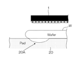
しかしながら、従来のこれら各種ウェーハ研磨装置においても、ウェーハWのエッジ部の形状が依然として所望の形状に形成されないという問題点が指摘されている。この現象を図9により説明する。 However, in these various conventional wafer polishing apparatuses, a problem has been pointed out that the shape of the edge portion of the wafer W is still not formed in a desired shape. This phenomenon will be described with reference to FIG.
この図9は、ウェーハWの左端部周辺の部分拡大断面図である。同図において、エアバッグ1によりゾーン加圧の押圧がなされており、ウェーハWの左端部における押圧力は、矢印で示されるように均一である。一方、ウェーハWの左端部に当接する研磨パッド20は、局所的に下方に押し潰された状態(20Aで表示)にある。
FIG. 9 is a partially enlarged cross-sectional view around the left end of the wafer W. In the same figure, the
このような場合、ウェーハWのエッジ部分の研磨量が他の部分よりも少なくなり、加工後のエッジ形状が盛り上がったような形状となってしまい、ウェーハWの品質上の欠陥となってしまう。 In such a case, the polishing amount of the edge portion of the wafer W becomes smaller than the other portions, and the edge shape after processing becomes a shape that rises, resulting in a defect in the quality of the wafer W.
これに対処すべく、エアバッグ1のゾーン加圧部分の幅を減少させ、局所的に潰された部分20Aの研磨圧を局所的に増大させることが考えられるものの、エアバッグ1の幅を所定長さ(たとえば、10mm)以下に加工することは、エアバッグ1の材質や押圧力等の制約があり現実的ではない。
In order to cope with this, although it is considered that the width of the zone pressurizing portion of the
本発明は、このような事情に鑑みてなされたもので、ウェーハの押圧力を全面に亘って所望の値に制御でき、特に、ウェーハのエッジ部分の押圧力を局所的に所望の値に制御でき、その結果、ウェーハの品質が保てるウェーハ研磨装置及び方法を提供することを目的とする。 The present invention has been made in view of such circumstances, and can control the pressing force of the wafer to a desired value over the entire surface, and in particular, control the pressing force of the edge portion of the wafer to a desired value locally. As a result, an object of the present invention is to provide a wafer polishing apparatus and method capable of maintaining the quality of a wafer.
本発明は、前記目的を達成するために、ウェーハを保持ヘッドで保持し、該保持ヘッドを介してウェーハを研磨パッドに押し付けて研磨するウェーハ研磨装置において、前記保持ヘッドは、ウェーハを前記研磨パッドに押し付けるキャリアと、該キャリアの周囲に配設されるリテーナーリングと、前記キャリアの下側に同心円状に配される円環状の複数の弾性部材と、前記弾性部材内部のエア室内に加圧ガスを供給するエア供給ラインと、を備え、最外周の前記弾性部材がウェーハの周縁部分を押圧する位置に配されるとともに、ウェーハの径方向に押圧力分布が形成されるように該最外周の弾性部材の押圧面が形成されていることを特徴とするウェーハ研磨装置を提供する。 In order to achieve the above object, the present invention provides a wafer polishing apparatus that holds a wafer with a holding head and presses the wafer against the polishing pad via the holding head to polish the wafer. A carrier to be pressed against the carrier, a retainer ring disposed around the carrier, a plurality of annular elastic members arranged concentrically below the carrier, and a pressurized gas in the air chamber inside the elastic member An air supply line for supplying the outer peripheral surface, and the elastic member on the outermost periphery is disposed at a position for pressing the peripheral portion of the wafer, and a pressure distribution is formed in the radial direction of the wafer. Provided is a wafer polishing apparatus in which a pressing surface of an elastic member is formed.
また、このために、本発明は、ウェーハを保持ヘッドで保持し、該保持ヘッドを介してウェーハを研磨パッドに押し付けて研磨するウェーハ研磨方法において、前記保持ヘッドに、ウェーハを前記研磨パッドに押し付けるキャリアと、該キャリアの周囲に配設されるリテーナーリングと、前記キャリアの下側に同心円状に配される円環状の複数の弾性部材と、前記弾性部材内部のエア室内に加圧ガスを供給するエア供給ラインと、を設け、最外周の前記弾性部材でウェーハの周縁部分を径方向に押圧力分布が形成されるように押圧することを特徴とするウェーハ研磨方法を提供する。 To this end, the present invention provides a wafer polishing method in which a wafer is held by a holding head, and the wafer is pressed against the polishing pad via the holding head to polish the wafer, and the wafer is pressed against the holding head against the holding head. A carrier, a retainer ring disposed around the carrier, a plurality of annular elastic members arranged concentrically below the carrier, and a pressurized gas supplied to an air chamber inside the elastic member An air supply line is provided, and the wafer polishing method is characterized in that the peripheral portion of the wafer is pressed by the outermost elastic member so that a pressing force distribution is formed in the radial direction.
本発明によれば、キャリアの下側に同心円状に配される円環状の複数の弾性部材を備え、最外周の弾性部材がウェーハの周縁部分を押圧する位置に配されるとともに、ウェーハの径方向に押圧力分布が形成されるように押圧面が形成されているので、ウェーハの周縁部分を径方向に押圧力分布が形成されるように押圧することができる。これにより、ウェーハのエッジ部分の押圧力を局所的に所望の値に制御でき、その結果、ウェーハの品質が保てる。 According to the present invention, it is provided with a plurality of annular elastic members arranged concentrically on the lower side of the carrier, the outermost elastic member is arranged at a position pressing the peripheral portion of the wafer, and the diameter of the wafer Since the pressing surface is formed so that the pressing force distribution is formed in the direction, the peripheral portion of the wafer can be pressed so that the pressing force distribution is formed in the radial direction. Thereby, the pressing force at the edge portion of the wafer can be locally controlled to a desired value, and as a result, the quality of the wafer can be maintained.
本発明において、前記最外周の弾性部材の押圧面が径方向に厚さ分布を持つように形成されていることが好ましい。このように、弾性部材の押圧面が径方向に厚さ分布を持つように形成されていれば、ウェーハの周縁部分を径方向に押圧力分布が形成されるように押圧することが容易にできる。なお、径方向に押圧力分布が形成されるように押圧するための他の構成としては、たとえば、弾性部材の厚さを均一とし、弾性部材の押圧面の所定の径部分に突条を形成する態様が採用できる。 In the present invention, the pressing surface of the outermost elastic member is preferably formed so as to have a thickness distribution in the radial direction. Thus, if the pressing surface of the elastic member is formed so as to have a thickness distribution in the radial direction, it is possible to easily press the peripheral portion of the wafer so that the pressing force distribution is formed in the radial direction. . In addition, as another structure for pressing so that a pressing force distribution is formed in the radial direction, for example, the thickness of the elastic member is made uniform, and a protrusion is formed on a predetermined diameter portion of the pressing surface of the elastic member. The mode to do can be adopted.
また、本発明において、前記弾性部材が、エチレンプロピレンゴム(EPDM)、シリコンゴム、ウレタンゴム、又はニトリルゴム(NBR)で形成されていることが好ましい。このような各種ゴム部材であれば、押圧部材として好適である。 In the present invention, the elastic member is preferably formed of ethylene propylene rubber (EPDM), silicon rubber, urethane rubber, or nitrile rubber (NBR). Such various rubber members are suitable as pressing members.
また、本発明において、前記弾性部材が、JIS K6301で規定するA硬度で20〜60であることが好ましい。このような特性の弾性部材であれば、押圧部材として好適である。 Moreover, in this invention, it is preferable that the said elastic member is 20-60 by A hardness prescribed | regulated by JISK6301. An elastic member having such characteristics is suitable as a pressing member.
また、本発明において、前記最外周の弾性部材の径方向の幅が10mm以下であることが好ましい。このような径方向の幅であれば、局所的な押圧の制御に好適である。 In the present invention, it is preferable that a radial width of the outermost elastic member is 10 mm or less. Such a radial width is suitable for local pressing control.
以上説明したように、本発明によれば、ウェーハのエッジ部分の押圧力を局所的に所望の値に制御でき、その結果、ウェーハの品質が保てる。 As described above, according to the present invention, the pressing force at the edge portion of the wafer can be locally controlled to a desired value, and as a result, the quality of the wafer can be maintained.
以下、添付図面に従って、本発明に係るウェーハ研磨装置及び方法の好ましい実施の形態について詳説する。 Hereinafter, preferred embodiments of a wafer polishing apparatus and method according to the present invention will be described in detail with reference to the accompanying drawings.
図1は、ウェーハ研磨装置10の全体構成を示す斜視図である。同図に示されるようにウェーハ研磨装置10は、主として研磨定盤12とウェーハ保持ヘッド14とで構成されている。
FIG. 1 is a perspective view showing the overall configuration of the
研磨定盤12は円盤状に形成され、その下面中央には回転軸16が連結されている。研磨定盤12は、この回転軸16に連結されたモータ18を駆動することにより矢印A方向に回転する。また、この研磨定盤12の上面には研磨パッド20が貼り付けられており、この研磨パッド20上に図示しないノズルからメカノケミカル研磨剤(スラリー)が供給される。
The
ウェーハ保持ヘッド14は、 図2に示されるように、主として保持ヘッド本体22、キャリア24、キャリア押圧手段26、リテーナーリング28、 リテーナーリング押圧手段30、保護シート52、エア等制御手段で構成されている。
As shown in FIG. 2, the
保持ヘッド本体22は円盤状に形成され、その上面中央には回転軸32(図1参照)が連結されている。保持ヘッド本体22は、この回転軸32に連結された図示しないモータに駆動されて図1の矢印B方向に回転する。
The holding head
キャリア24は円盤状に形成され、保持ヘッド本体22の下部中央に配置されている。キャリア24の上面中央部と保持ヘッド本体22の中央下部との間にはドライブプレート34が設けられており、ピン36を介して保持ヘッド本体22から回転が伝達される。
The
ドライブプレート34の中央下部とキャリア24の中央上部との間には作動トランス38が設けられており、保持ヘッド本体22に対するキャリア24の上下移動量が高精度で検出できるようになっている。具体的には、ドライブプレート34の中央下部には作動トランス本体38Aが固定されており、キャリア24の中央上部には作動トランスのコア38Bが固定されている。
An
また、キャリア24の上面周縁部にはキャリア押圧部材40が設けられている。キャリア24は、このキャリア押圧部材40を介してキャリア押圧手段26から押圧力が伝達される。
Further, a
また、キャリア24の下面には、エアを吸引したり純水(DIW)を噴射する供給経路である吸引・吹出溝42が形成されている。この吸引・吹出溝42には、キャリア24の内部に形成された流体流路(図示略)が連通されている。流体流路には図示しない流体配管を介して吸気ポンプと純水供給源が接続されている。吸引・吹出溝42からのエアの吸引と純水の吹出は、この吸気ポンプと純水供給源とを切り替えることにより行われる。
Further, a suction /
上記の吸引・吹出溝42、流体流路、流体配管、吸気ポンプ、純水供給源、及び、吸気ポンプと純水供給源との切り替え手段、等でエア制御手段が構成される。
The above-described suction / blowing
キャリア押圧手段26は、保持ヘッド本体22下面の中央部周縁に配置され、キャリア押圧部材40に押圧力を与えることにより、これに結合されたキャリア24に押圧力を伝達する。このキャリア押圧手段26は、好ましくはエアの吸排気により膨張収縮するゴムシート製のエアバッグ46で構成される。エアバッグ46にはエアを供給するための空気供給機構48が連結され、この空気供給機構48には、図示しないポンプから圧送されるエアの圧力を調整するレギュレータ(不図示)が具備される。
The
なお、エアバッグ46の材質はゴムシート、たとえば、クロロプレンゴムが好ましいが、それ以外の材料、たとえば、可撓性のある樹脂材料でも使用できる。
The
リテーナーリング28は、リング状に形成され、キャリア24の外周に配置される。このリテーナーリング28は、ウェーハ保持ヘッド14に設けられたホルダ(リテーナーリングホルダ)50に取り付けられ、その内周部には必要に応じて保護シート(図示略)が張設できるようになっている。なお、図2の構成では、キャリア24の下面の全面を覆う保護シートに代えて、後述する保護シート52A、52B、52C、及びゾーンゴム環52Dが採用されている。
The retainer ring 28 is formed in a ring shape and is disposed on the outer periphery of the
リテーナーリングホルダ50はリング状に形成され、その下面には環状の凹部54が形成されている。一方、リテーナーリング28の上面には、この凹部54に嵌合する凸部56が形成されており、この凸部56をリテーナーリングホルダ50の凹部54に嵌合させることにより、リテーナーリング28がリテーナーリングホルダ50に装着される。
The retainer ring holder 50 is formed in a ring shape, and an
リテーナーリング28は、その凸部56をリテーナーリングホルダ50の凹部54に嵌合させた後、図示しない複数のボルトでねじ止めすることにより、リテーナーリングホルダ50に固定される。このため、リテーナーリング28には、一定の間隔でねじ孔(図示略)が形成され、リテーナーリングホルダ50には一定の間隔で貫通孔(図示略)が形成されている。
The retainer ring 28 is fixed to the retainer ring holder 50 by fitting the
このリテーナーリング28及びリテーナーリングホルダ50の組み合わせは、キャリア24の下面の全面を覆う保護シートを張設する際に好適に使用される。
The combination of the retainer ring 28 and the retainer ring holder 50 is preferably used when a protective sheet covering the entire lower surface of the
リテーナーリングホルダ50は、リング状に形成された取付部材64にスナップリング66を介して取り付けられている。取付部材64には、リテーナーリング押圧部材68が連結されている。リテーナーリング28は、このリテーナーリング押圧部材68を介してリテーナーリング押圧手段30からの押圧力が伝達される。 The retainer ring holder 50 is attached to an attachment member 64 formed in a ring shape via a snap ring 66. A retainer ring pressing member 68 is connected to the mounting member 64. The retainer ring 28 is transmitted with a pressing force from the retainer ring pressing means 30 via the retainer ring pressing member 68.
リテーナーリング押圧手段30は、保持ヘッド本体22の下面の外周部に配置され、リテーナーリング押圧部材68に押圧力を与えることにより、これに結合しているリテーナーリング28を研磨パッド20に押し付ける。このリテーナーリング押圧手段30も、好ましくはキャリア押圧手段26と同様にゴムシート製のエアバッグ70で構成される。エアバッグ70にはエアを供給するための空気供給機構72が連結され、この空気供給機構72には、図示しないポンプから圧送されるエアの圧力を調整するレギュレータ(不図示)が具備される。
The retainer ring pressing means 30 is disposed on the outer peripheral portion of the lower surface of the holding head
なお、エアバッグ70の材質はゴムシート、たとえば、クロロプレンゴムが好ましいが、それ以外の材料、たとえば、可撓性のある樹脂材料でも使用できる。
The
キャリア24の下面には同心円状の溝が3箇所設けられており、この溝24A、24B、24Cを覆うように弾性部材である保護シート52A、52B、52C、及びゾーンゴム環52Dが取り付けられており、この保護シート52A、52B、52C、及びゾーンゴム環52Dによりそれぞれエアバッグが構成されている。
Three concentric grooves are provided on the lower surface of the
このエアバッグ(保護シート52A、52B、52C、及びゾーンゴム環52D)には、キャリア24の内部に形成されたエア流路(図示略)が連通されている。エア流路には図示しないエア配管及び圧力制御弁を介してエア供給源が接続されている。そして、それぞれのエアバッグ(保護シート52A、52B、52C、及びゾーンゴム環52D)内のエア圧が独立して制御可能となっている。
An air flow path (not shown) formed inside the
キャリア24の下面の最外周の溝24Cの内部において、内周側には保護シート52Cが、外周側(図の円aの内部)にはゾーンゴム環52Dが配されている。このゾーンゴム環52Dは、断面が上向きコ字状(チャンネル状)の弾性部材である。このゾーンゴム環52Dの配置、及び断面形状の例を図3に示す。
Within the outermost
このゾーンゴム環52Dは、押圧面53Aと、押圧面53Aの両端より垂設される側壁面53B(外周側)及び53C(内周側)と、側壁面53B及び53Cの上端より内側に垂設される張り出し辺53D及び53Eとより構成される。そして、ゾーンゴム環52Dの内部53Fにエア圧が印加されることにより、ゾーンゴム環52Dが押圧手段として機能する。
This
この弾性部材であるゾーンゴム環52Dの材質として特に制限はないが、エチレンプロピレンゴム(EPDM)、シリコンゴム、ウレタンゴム、又はニトリルゴム(NBR)であることが好ましい。このような部材であれば、可撓性、耐久性、耐汚染性等にすぐれており、本発明の目的にふさわしいからである。
Although there is no restriction | limiting in particular as a material of the
また、このゾーンゴム環52Dは、JIS K6301で規定するA硬度で20〜60であることが好ましい。このような部材であれば、適度な可撓性を備え、本発明の目的にふさわしいからである。
Further, the
ゾーンゴム環52Dの厚さについて特に制限はないが、0.4〜1.0mmの範囲が好ましい。0.4mm未満では、耐久性が劣る場合があり、一方、1.0mm超では、可撓性が劣る場合があるからである。
Although there is no restriction | limiting in particular about the thickness of
ゾーンゴム環52Dの径方向の幅、すなわち押圧面53Aの幅について特に制限はないが、10mm以下であることが好ましい。このような幅であれば、ウェーハのエッジ部分の局所的な押圧の制御に好適であるからである。
The width in the radial direction of the
ゾーンゴム環52Dの内部53Fへの供給圧力について特に制限はないが、1〜100kPaの範囲が好ましい。
Although there is no restriction | limiting in particular about the supply pressure to the inside 53F of the
ゾーンゴム環52Dの押圧面53Aは、径方向(図3の左右方向)に厚さ分布を持つように形成されていることが好ましい。以下、この作用について説明する。図4は、ゾーンゴム環52Dの構成を示す断面図、及び押圧面53Aの厚さ分布に対応する圧力分布を示す図である。なお、図4の括弧内の符号j、f、gは、後述する図5の断面図の符号に対応させたものである。
The
図4(j)は、押圧面53Aの厚さが均一(厚さ分布がない)従来例のゾーンゴム環であり、圧力分布も略均一になっている。
FIG. 4J shows a conventional zone rubber ring having a uniform
図4(f)は、押圧面53Aの上面が直線状であり、下面が下に凸の円弧状であり、押圧面53Aの厚さ分布もこれに対応するような中央部が厚く、左右に線対称な形状である。したがって、圧力分布もこれに対応した、中央部が高く、左右に向って減少するパターンとなっている。
In FIG. 4 (f), the upper surface of the
図4(g)は、押圧面53Aの右側約1/3が他の部分の約2倍の厚さとなっており、この部分がステップ状に下に凸となっている。したがって、圧力分布もこれに対応した、右側が高く、左側に向って減少するパターンとなっている。
In FIG. 4G, about 右側 on the right side of the
このように、図4(f)及び(g)のゾーンゴム環52Dは、図4(j)の従来例と異なり、押圧面53Aに厚さ分布を形成することにより、これに対応した所望の圧力分布が得られるようになっている。以下、同様の各例を図5により説明する。
As described above, the
図5は、ゾーンゴム環52Dの構成を示す断面図である。なお、ここで示されるゾーンゴム環52Dは、既述の図3及び図4と異なり、左右方向の右側が内周側(側壁面53C)であり、左側が外周側(側壁面53B)である。
FIG. 5 is a cross-sectional view showing the configuration of the
図5(a)は、押圧面53Aの上面が水平な直線状であり、下面が左側(外周側)に向って下がる直線状であり、押圧面53Aの厚さ分布もこれに対応するような内周側から外周側に向って直線的に(1次の相関で)増大するテーパ状となっている。
In FIG. 5A, the upper surface of the
図5(b)は、押圧面53Aの上面が水平な直線状であり、下面が右側(内周側)に向って下がる直線状であり、押圧面53Aの厚さ分布もこれに対応するような外周側から内周側に向って直線的に(1次の相関で)増大するテーパ状となっている。
In FIG. 5 (b), the upper surface of the
図5(c)は、押圧面53Aの上面が水平な直線状であり、下面がV字状であり、押圧面53Aの厚さ分布もこれに対応するような中央から両側に向って直線的に(1次の相関で)減少する山形となっている。
In FIG. 5C, the upper surface of the
図5(d)は、押圧面53Aの上面が水平な直線状であり、下面も水平な直線状であるが、下面の中央部にステップ状の突起が形成されており、押圧面53Aの厚さ分布もこれに対応するように、突起部のみ他の部分の約2倍の厚さとなっている。
In FIG. 5D, the upper surface of the
図5(e)は、押圧面53Aの上面が水平な直線状であり、下面も水平な直線状であるが、下面の中央部に円弧状の突起が形成されており、押圧面53Aの厚さ分布もこれに対応するように、突起部のみ他の部分より厚くなっている。
In FIG. 5E, the upper surface of the
図5(f)及び(g)は、図4により既述のものである。 FIGS. 5 (f) and 5 (g) are as described above with reference to FIG.
図5(h)及び(i)は、これまで説明した各例と異なり、押圧面53Aの厚さが均一(厚さ分布がない)のものである。
FIGS. 5H and 5I are different from the examples described so far in that the
図5(h)は、押圧面53Aの下面の中央部にステップ状の突起が形成されており、上面の中央部もこれに倣うように凹状に形成されている。このような構成によっても、中央部の押圧力を局所的に増大させることができる。
In FIG. 5H, a step-like protrusion is formed at the center of the lower surface of the
図5(i)は、押圧面53Aの左側(外周側)約1/3にステップ状の突起が形成されており、上面の左側(外周側)約1/3もこれに倣うように凹状に形成されている。このような構成によっても、左側(外周側)の押圧力を局所的に増大させることができる。
In FIG. 5 (i), a step-like protrusion is formed on the left side (outer peripheral side) of about 1/3 of the
図5(j)は、図4により既述の従来例である。 FIG. 5 (j) is a conventional example already described with reference to FIG.
前記のように構成されたウェーハ研磨装置10のウェーハ研磨方法は次のとおりである。
The wafer polishing method of the
先ず、ウェーハWをウェーハ保持ヘッド14で保持して研磨パッド20上に載置する。この際、キャリア24の下面に形成された吸引・吹出溝42を用いウェーハWを吸引保持する。
First, the wafer W is held by the
次に、図示しないポンプからエアバック46、70にエアを供給する。これと同時にキャリア24の各エアバッグ(保護シート52A、52B、52C、及びゾーンゴム環52D)にエアを供給する(供給圧力1〜100kPa)。これにより、各エアバッグの内圧が高くなる。次に、エアバッグ46、70が膨らみ、ウェーハWとリテーナーリング28が所定の圧力で研磨パッド20に押し付けられる。この状態で研磨定盤12を図1の矢印A方向に回転させるとともに、ウェーハ保持ヘッド14を図1の矢印B方向に回転させる。そして、その回転する研磨パッド20上に図示しないノズルからスラリーを供給する。これにより、ウェーハWの下面が研磨パッド20により研磨される。
Next, air is supplied to the
研磨の際におけるウェーハWのエッジ部分について図6により説明する。図6は、ウェーハWの左端部周辺の部分拡大断面図であり、ゾーンゴム環52Dとして図5(g)のタイプを使用した例である。この図6は、従来例を示す既述の図9に対応する。
The edge portion of the wafer W during polishing will be described with reference to FIG. FIG. 6 is a partially enlarged sectional view around the left end portion of the wafer W, and is an example in which the type of FIG. 5G is used as the
ゾーンゴム環52Dの下方に示される複数の矢印は、ゾーンゴム環52Dのそれぞれの箇所における押圧力である。このように、ゾーンゴム環52Dの幅方向(径方向)に押圧力分布を形成することができるので、従来の研磨においてウェーハWのエッジ部分にかかる不均一な押圧力を補正することができ(局所的に所望の値に制御でき)、その結果、ウェーハWの研磨品質が保てる。
A plurality of arrows shown below the
以上に説明した構成は、本発明の実施形態であるが、本発明の構成はこれらに限定されるものではなく、各種の構成が採り得る。 The configuration described above is an embodiment of the present invention, but the configuration of the present invention is not limited to these, and various configurations can be adopted.
たとえば、本発明の実施形態では、図2に示されるウェーハ保持ヘッド14を使用しているが、これ以外の各種構成のウェーハ保持ヘッドを使用してもよく、これらの構成であっても本実施形態と同様の効果が得られる。
For example, in the embodiment of the present invention, the
具体的には、図2に示されるウェーハ保持ヘッド14におけるエアバッグ(保護シート52A、52B、52C)に代えて、リテーナーリング28の内側に張設されキャリア24の下面の全面を覆う保護シートを採用することができる。したがって、ゾーンゴム環52Dは、この保護シートの裏面に配されることとなる。
Specifically, instead of the airbags (
この場合、保護シートは、円形状に形成され、複数の孔が開けられ、周縁部がリテーナーリング28とリテーナーリングホルダ50との間で挟持されることにより、リテーナーリング28の内側に張設されることとなる。 In this case, the protective sheet is formed in a circular shape, a plurality of holes are formed, and the peripheral edge portion is sandwiched between the retainer ring 28 and the retainer ring holder 50, thereby being stretched inside the retainer ring 28. The Rukoto.
この保護シートが張設されたキャリア24の下部には、キャリア24と保護シートとの間にエア層が形成される。ウェーハWは、このエア層を介してキャリア24に押圧される。このエア層は、キャリア24の吹出溝42からエアを吹出すことにより内圧が高められる。保護シートに形成された孔は、ウェーハWを保持して搬送する際には吸着用の孔として作用する。研磨時には、この孔からエアが連通するので、保護シートはエア層74中に介在するだけで、ウェーハWの裏面には作用しない。
An air layer is formed between the
ただし、ゾーンゴム環52Dは押圧力が独自に制御されるので、本実施形態の例と同様に作用する。
However, since the pressing force of the
10…ウェーハ研磨装置、12…研磨定盤、14…ウェーハ保持ヘッド、20…研磨パッド、22…保持ヘッド本体、24…キャリア、26…キャリア押圧手段、28…リテーナーリング、30…リテーナーリング押圧手段、46…エアバッグ、52A、52B、52C…保護シート、52D…ゾーンゴム環、70…エアバッグ、W…ウェーハ
DESCRIPTION OF
Claims (6)
前記保持ヘッドは、
ウェーハを前記研磨パッドに押し付けるキャリアと、
該キャリアの周囲に配設されるリテーナーリングと、
前記キャリアの下側に同心円状に配される円環状の複数の弾性部材と、
前記弾性部材内部のエア室内に加圧ガスを供給するエア供給ラインと、を備え、
最外周の前記弾性部材がウェーハの周縁部分を押圧する位置に配されるとともに、ウェーハの径方向に押圧力分布が形成されるように該最外周の弾性部材の押圧面が形成されていることを特徴とするウェーハ研磨装置。 In a wafer polishing apparatus for holding a wafer with a holding head and pressing the wafer against the polishing pad via the holding head for polishing,
The holding head is
A carrier for pressing a wafer against the polishing pad;
A retainer ring disposed around the carrier;
A plurality of annular elastic members disposed concentrically below the carrier;
An air supply line for supplying pressurized gas into the air chamber inside the elastic member,
The outermost elastic member is arranged at a position for pressing the peripheral portion of the wafer, and the pressing surface of the outermost elastic member is formed so that a pressing force distribution is formed in the radial direction of the wafer. A wafer polishing apparatus.
前記保持ヘッドに、
ウェーハを前記研磨パッドに押し付けるキャリアと、
該キャリアの周囲に配設されるリテーナーリングと、
前記キャリアの下側に同心円状に配される円環状の複数の弾性部材と、
前記弾性部材内部のエア室内に加圧ガスを供給するエア供給ラインと、を設け、
最外周の前記弾性部材でウェーハの周縁部分を径方向に押圧力分布が形成されるように押圧することを特徴とするウェーハ研磨方法。
In a wafer polishing method of holding a wafer with a holding head and polishing the wafer by pressing the wafer against a polishing pad via the holding head,
In the holding head,
A carrier for pressing a wafer against the polishing pad;
A retainer ring disposed around the carrier;
A plurality of annular elastic members disposed concentrically below the carrier;
An air supply line for supplying pressurized gas into the air chamber inside the elastic member,
A wafer polishing method, wherein the outer peripheral elastic member presses a peripheral portion of a wafer so that a pressing force distribution is formed in a radial direction.
Priority Applications (1)
| Application Number | Priority Date | Filing Date | Title |
|---|---|---|---|
| JP2006089270A JP2007266299A (en) | 2006-03-28 | 2006-03-28 | Wafer-polishing apparatus and method |
Applications Claiming Priority (1)
| Application Number | Priority Date | Filing Date | Title |
|---|---|---|---|
| JP2006089270A JP2007266299A (en) | 2006-03-28 | 2006-03-28 | Wafer-polishing apparatus and method |
Publications (1)
| Publication Number | Publication Date |
|---|---|
| JP2007266299A true JP2007266299A (en) | 2007-10-11 |
Family
ID=38638997
Family Applications (1)
| Application Number | Title | Priority Date | Filing Date |
|---|---|---|---|
| JP2006089270A Pending JP2007266299A (en) | 2006-03-28 | 2006-03-28 | Wafer-polishing apparatus and method |
Country Status (1)
| Country | Link |
|---|---|
| JP (1) | JP2007266299A (en) |
Cited By (4)
| Publication number | Priority date | Publication date | Assignee | Title |
|---|---|---|---|---|
| CN102632452A (en) * | 2012-04-24 | 2012-08-15 | 浙江金瑞泓科技股份有限公司 | Polishing method for silicon wafer by utilizing water ring |
| KR20210004394A (en) * | 2019-07-04 | 2021-01-13 | 주식회사 맥스텍 | retainer ring device |
| KR20230032118A (en) * | 2021-08-30 | 2023-03-07 | 에스케이실트론 주식회사 | Multi-Area Control Grinding Head |
| KR20250142016A (en) * | 2024-03-21 | 2025-09-30 | 에스케이실트론 주식회사 | Polishing head with multi-zone control |
-
2006
- 2006-03-28 JP JP2006089270A patent/JP2007266299A/en active Pending
Cited By (7)
| Publication number | Priority date | Publication date | Assignee | Title |
|---|---|---|---|---|
| CN102632452A (en) * | 2012-04-24 | 2012-08-15 | 浙江金瑞泓科技股份有限公司 | Polishing method for silicon wafer by utilizing water ring |
| KR20210004394A (en) * | 2019-07-04 | 2021-01-13 | 주식회사 맥스텍 | retainer ring device |
| KR102223838B1 (en) | 2019-07-04 | 2021-03-05 | 주식회사 맥스텍 | retainer ring device |
| KR20230032118A (en) * | 2021-08-30 | 2023-03-07 | 에스케이실트론 주식회사 | Multi-Area Control Grinding Head |
| KR102582347B1 (en) | 2021-08-30 | 2023-09-25 | 에스케이실트론 주식회사 | Multi-Area Control Grinding Head |
| KR20250142016A (en) * | 2024-03-21 | 2025-09-30 | 에스케이실트론 주식회사 | Polishing head with multi-zone control |
| KR102883693B1 (en) | 2024-03-21 | 2025-11-10 | 에스케이실트론 주식회사 | Polishing head with multi-zone control |
Similar Documents
| Publication | Publication Date | Title |
|---|---|---|
| US6450868B1 (en) | Carrier head with multi-part flexible membrane | |
| US6361419B1 (en) | Carrier head with controllable edge pressure | |
| US7357699B2 (en) | Substrate holding apparatus and polishing apparatus | |
| CN101444897B (en) | Polishing apparatus and method | |
| US8298047B2 (en) | Substrate retainer | |
| US6872130B1 (en) | Carrier head with non-contact retainer | |
| US6755726B2 (en) | Polishing head with a floating knife-edge | |
| CN102380820A (en) | Polishing apparatus | |
| JP3683149B2 (en) | Structure of polishing head of polishing apparatus | |
| JP5236705B2 (en) | Polishing equipment | |
| CN100468643C (en) | Substrate holding device and polishing device | |
| US6840845B2 (en) | Wafer polishing apparatus | |
| JP4583729B2 (en) | Substrate holding device, polishing device, and elastic member used in the substrate holding device | |
| JP2007266299A (en) | Wafer-polishing apparatus and method | |
| JP2005011999A (en) | Workpiece holding head and polishing apparatus having the same | |
| JP7349791B2 (en) | CMP equipment | |
| JP3969069B2 (en) | Wafer polishing equipment | |
| JP2002198339A (en) | Wafer polishing equipment | |
| JP4822744B2 (en) | Chemical mechanical polishing equipment, carrier head and compartment ring | |
| JP4930680B2 (en) | Wafer polishing apparatus and method | |
| JP2008188767A (en) | Substrate holding apparatus | |
| JP4620072B2 (en) | Polishing device | |
| JP2005088171A (en) | Work holding head and polishing device having work holding head | |
| JP2005019440A (en) | Work holding head and polishing device having the same | |
| JP2017162859A (en) | Wafer polishing apparatus |