JP2022541862A - surface treatment equipment - Google Patents
surface treatment equipment Download PDFInfo
- Publication number
- JP2022541862A JP2022541862A JP2020558902A JP2020558902A JP2022541862A JP 2022541862 A JP2022541862 A JP 2022541862A JP 2020558902 A JP2020558902 A JP 2020558902A JP 2020558902 A JP2020558902 A JP 2020558902A JP 2022541862 A JP2022541862 A JP 2022541862A
- Authority
- JP
- Japan
- Prior art keywords
- frame
- surface treatment
- lifting
- rotation
- treatment equipment
- Prior art date
- Legal status (The legal status is an assumption and is not a legal conclusion. Google has not performed a legal analysis and makes no representation as to the accuracy of the status listed.)
- Pending
Links
Images




Classifications
-
- H—ELECTRICITY
- H05—ELECTRIC TECHNIQUES NOT OTHERWISE PROVIDED FOR
- H05K—PRINTED CIRCUITS; CASINGS OR CONSTRUCTIONAL DETAILS OF ELECTRIC APPARATUS; MANUFACTURE OF ASSEMBLAGES OF ELECTRICAL COMPONENTS
- H05K3/00—Apparatus or processes for manufacturing printed circuits
- H05K3/0085—Apparatus for treatments of printed circuits with liquids not provided for in groups H05K3/02 - H05K3/46; conveyors and holding means therefor
-
- B—PERFORMING OPERATIONS; TRANSPORTING
- B05—SPRAYING OR ATOMISING IN GENERAL; APPLYING FLUENT MATERIALS TO SURFACES, IN GENERAL
- B05B—SPRAYING APPARATUS; ATOMISING APPARATUS; NOZZLES
- B05B16/00—Spray booths
- B05B16/90—Spray booths comprising conveying means for moving objects or other work to be sprayed in and out of the booth, e.g. through the booth
-
- B—PERFORMING OPERATIONS; TRANSPORTING
- B05—SPRAYING OR ATOMISING IN GENERAL; APPLYING FLUENT MATERIALS TO SURFACES, IN GENERAL
- B05B—SPRAYING APPARATUS; ATOMISING APPARATUS; NOZZLES
- B05B13/00—Machines or plants for applying liquids or other fluent materials to surfaces of objects or other work by spraying, not covered by groups B05B1/00 - B05B11/00
- B05B13/02—Means for supporting work; Arrangement or mounting of spray heads; Adaptation or arrangement of means for feeding work
- B05B13/04—Means for supporting work; Arrangement or mounting of spray heads; Adaptation or arrangement of means for feeding work the spray heads being moved during spraying operation
- B05B13/0405—Means for supporting work; Arrangement or mounting of spray heads; Adaptation or arrangement of means for feeding work the spray heads being moved during spraying operation with reciprocating or oscillating spray heads
- B05B13/041—Means for supporting work; Arrangement or mounting of spray heads; Adaptation or arrangement of means for feeding work the spray heads being moved during spraying operation with reciprocating or oscillating spray heads with spray heads reciprocating along a straight line
-
- B—PERFORMING OPERATIONS; TRANSPORTING
- B05—SPRAYING OR ATOMISING IN GENERAL; APPLYING FLUENT MATERIALS TO SURFACES, IN GENERAL
- B05B—SPRAYING APPARATUS; ATOMISING APPARATUS; NOZZLES
- B05B13/00—Machines or plants for applying liquids or other fluent materials to surfaces of objects or other work by spraying, not covered by groups B05B1/00 - B05B11/00
- B05B13/02—Means for supporting work; Arrangement or mounting of spray heads; Adaptation or arrangement of means for feeding work
- B05B13/04—Means for supporting work; Arrangement or mounting of spray heads; Adaptation or arrangement of means for feeding work the spray heads being moved during spraying operation
- B05B13/0442—Installation or apparatus for applying liquid or other fluent material to separate articles rotated during spraying operation
-
- B—PERFORMING OPERATIONS; TRANSPORTING
- B05—SPRAYING OR ATOMISING IN GENERAL; APPLYING FLUENT MATERIALS TO SURFACES, IN GENERAL
- B05B—SPRAYING APPARATUS; ATOMISING APPARATUS; NOZZLES
- B05B15/00—Details of spraying plant or spraying apparatus not otherwise provided for; Accessories
- B05B15/70—Arrangements for moving spray heads automatically to or from the working position
-
- B—PERFORMING OPERATIONS; TRANSPORTING
- B25—HAND TOOLS; PORTABLE POWER-DRIVEN TOOLS; MANIPULATORS
- B25J—MANIPULATORS; CHAMBERS PROVIDED WITH MANIPULATION DEVICES
- B25J11/00—Manipulators not otherwise provided for
- B25J11/0075—Manipulators for painting or coating
-
- B—PERFORMING OPERATIONS; TRANSPORTING
- B25—HAND TOOLS; PORTABLE POWER-DRIVEN TOOLS; MANIPULATORS
- B25J—MANIPULATORS; CHAMBERS PROVIDED WITH MANIPULATION DEVICES
- B25J9/00—Program-controlled manipulators
- B25J9/10—Program-controlled manipulators characterised by positioning means for manipulator elements
- B25J9/105—Program-controlled manipulators characterised by positioning means for manipulator elements using eccentric means
-
- B—PERFORMING OPERATIONS; TRANSPORTING
- B65—CONVEYING; PACKING; STORING; HANDLING THIN OR FILAMENTARY MATERIAL
- B65G—TRANSPORT OR STORAGE DEVICES, e.g. CONVEYORS FOR LOADING OR TIPPING, SHOP CONVEYOR SYSTEMS OR PNEUMATIC TUBE CONVEYORS
- B65G19/00—Conveyors comprising an impeller or a series of impellers carried by an endless traction element and arranged to move articles or materials over a supporting surface or underlying material, e.g. endless scraper conveyors
- B65G19/02—Conveyors comprising an impeller or a series of impellers carried by an endless traction element and arranged to move articles or materials over a supporting surface or underlying material, e.g. endless scraper conveyors for articles, e.g. for containers
- B65G19/025—Conveyors comprising an impeller or a series of impellers carried by an endless traction element and arranged to move articles or materials over a supporting surface or underlying material, e.g. endless scraper conveyors for articles, e.g. for containers for suspended articles
-
- H—ELECTRICITY
- H05—ELECTRIC TECHNIQUES NOT OTHERWISE PROVIDED FOR
- H05K—PRINTED CIRCUITS; CASINGS OR CONSTRUCTIONAL DETAILS OF ELECTRIC APPARATUS; MANUFACTURE OF ASSEMBLAGES OF ELECTRICAL COMPONENTS
- H05K3/00—Apparatus or processes for manufacturing printed circuits
- H05K3/22—Secondary treatment of printed circuits
- H05K3/26—Cleaning or polishing of the conductive pattern
-
- H—ELECTRICITY
- H10—SEMICONDUCTOR DEVICES; ELECTRIC SOLID-STATE DEVICES NOT OTHERWISE PROVIDED FOR
- H10P—GENERIC PROCESSES OR APPARATUS FOR THE MANUFACTURE OR TREATMENT OF DEVICES COVERED BY CLASS H10
- H10P72/00—Handling or holding of wafers, substrates or devices during manufacture or treatment thereof
- H10P72/04—Apparatus for manufacture or treatment
- H10P72/0402—Apparatus for fluid treatment
- H10P72/0406—Apparatus for fluid treatment for cleaning followed by drying, rinsing, stripping, blasting or the like
- H10P72/0411—Apparatus for fluid treatment for cleaning followed by drying, rinsing, stripping, blasting or the like for wet cleaning or washing
- H10P72/0414—Apparatus for fluid treatment for cleaning followed by drying, rinsing, stripping, blasting or the like for wet cleaning or washing using mainly spraying means, e.g. nozzles
-
- H—ELECTRICITY
- H10—SEMICONDUCTOR DEVICES; ELECTRIC SOLID-STATE DEVICES NOT OTHERWISE PROVIDED FOR
- H10P—GENERIC PROCESSES OR APPARATUS FOR THE MANUFACTURE OR TREATMENT OF DEVICES COVERED BY CLASS H10
- H10P72/00—Handling or holding of wafers, substrates or devices during manufacture or treatment thereof
- H10P72/04—Apparatus for manufacture or treatment
- H10P72/0402—Apparatus for fluid treatment
- H10P72/0418—Apparatus for fluid treatment for etching
- H10P72/0422—Apparatus for fluid treatment for etching for wet etching
- H10P72/0424—Apparatus for fluid treatment for etching for wet etching using mainly spraying means, e.g. nozzles
-
- H—ELECTRICITY
- H05—ELECTRIC TECHNIQUES NOT OTHERWISE PROVIDED FOR
- H05K—PRINTED CIRCUITS; CASINGS OR CONSTRUCTIONAL DETAILS OF ELECTRIC APPARATUS; MANUFACTURE OF ASSEMBLAGES OF ELECTRICAL COMPONENTS
- H05K2203/00—Indexing scheme relating to apparatus or processes for manufacturing printed circuits covered by H05K3/00
- H05K2203/01—Tools for processing; Objects used during processing
- H05K2203/0147—Carriers and holders
- H05K2203/0165—Holder for holding a Printed Circuit Board [PCB] during processing, e.g. during screen printing
-
- H—ELECTRICITY
- H05—ELECTRIC TECHNIQUES NOT OTHERWISE PROVIDED FOR
- H05K—PRINTED CIRCUITS; CASINGS OR CONSTRUCTIONAL DETAILS OF ELECTRIC APPARATUS; MANUFACTURE OF ASSEMBLAGES OF ELECTRICAL COMPONENTS
- H05K2203/00—Indexing scheme relating to apparatus or processes for manufacturing printed circuits covered by H05K3/00
- H05K2203/07—Treatments involving liquids, e.g. plating, rinsing
- H05K2203/0736—Methods for applying liquids, e.g. spraying
-
- H—ELECTRICITY
- H05—ELECTRIC TECHNIQUES NOT OTHERWISE PROVIDED FOR
- H05K—PRINTED CIRCUITS; CASINGS OR CONSTRUCTIONAL DETAILS OF ELECTRIC APPARATUS; MANUFACTURE OF ASSEMBLAGES OF ELECTRICAL COMPONENTS
- H05K2203/00—Indexing scheme relating to apparatus or processes for manufacturing printed circuits covered by H05K3/00
- H05K2203/07—Treatments involving liquids, e.g. plating, rinsing
- H05K2203/0736—Methods for applying liquids, e.g. spraying
- H05K2203/075—Global treatment of printed circuits by fluid spraying, e.g. cleaning a conductive pattern using nozzles
-
- H—ELECTRICITY
- H05—ELECTRIC TECHNIQUES NOT OTHERWISE PROVIDED FOR
- H05K—PRINTED CIRCUITS; CASINGS OR CONSTRUCTIONAL DETAILS OF ELECTRIC APPARATUS; MANUFACTURE OF ASSEMBLAGES OF ELECTRICAL COMPONENTS
- H05K2203/00—Indexing scheme relating to apparatus or processes for manufacturing printed circuits covered by H05K3/00
- H05K2203/07—Treatments involving liquids, e.g. plating, rinsing
- H05K2203/0756—Uses of liquids, e.g. rinsing, coating, dissolving
-
- H—ELECTRICITY
- H05—ELECTRIC TECHNIQUES NOT OTHERWISE PROVIDED FOR
- H05K—PRINTED CIRCUITS; CASINGS OR CONSTRUCTIONAL DETAILS OF ELECTRIC APPARATUS; MANUFACTURE OF ASSEMBLAGES OF ELECTRICAL COMPONENTS
- H05K2203/00—Indexing scheme relating to apparatus or processes for manufacturing printed circuits covered by H05K3/00
- H05K2203/15—Position of the PCB during processing
- H05K2203/1518—Vertically held PCB
-
- H—ELECTRICITY
- H05—ELECTRIC TECHNIQUES NOT OTHERWISE PROVIDED FOR
- H05K—PRINTED CIRCUITS; CASINGS OR CONSTRUCTIONAL DETAILS OF ELECTRIC APPARATUS; MANUFACTURE OF ASSEMBLAGES OF ELECTRICAL COMPONENTS
- H05K2203/00—Indexing scheme relating to apparatus or processes for manufacturing printed circuits covered by H05K3/00
- H05K2203/15—Position of the PCB during processing
- H05K2203/1554—Rotating or turning the PCB in a continuous manner
-
- H—ELECTRICITY
- H05—ELECTRIC TECHNIQUES NOT OTHERWISE PROVIDED FOR
- H05K—PRINTED CIRCUITS; CASINGS OR CONSTRUCTIONAL DETAILS OF ELECTRIC APPARATUS; MANUFACTURE OF ASSEMBLAGES OF ELECTRICAL COMPONENTS
- H05K2203/00—Indexing scheme relating to apparatus or processes for manufacturing printed circuits covered by H05K3/00
- H05K2203/15—Position of the PCB during processing
- H05K2203/1572—Processing both sides of a PCB by the same process; Providing a similar arrangement of components on both sides; Making interlayer connections from two sides
Landscapes
- Engineering & Computer Science (AREA)
- Manufacturing & Machinery (AREA)
- Microelectronics & Electronic Packaging (AREA)
- Mechanical Engineering (AREA)
- Robotics (AREA)
- Spray Control Apparatus (AREA)
- Catching Or Destruction (AREA)
- Special Spraying Apparatus (AREA)
- Cleaning By Liquid Or Steam (AREA)
- Cleaning Or Drying Semiconductors (AREA)
Abstract
本願では表面処理機器を提案し、当該表面処理機器は、機器フレーム11と、円盤ハンガー40と、円盤ハンガー40を協力して支持するための二つの支持輪51と、二つの支持輪51上に支持された円盤ハンガー40の回転を駆動するための回転駆動機構60と、円盤ハンガー40上の回路基板に液体薬品をスプレーするための垂直スプレーフレーム20と、垂直スプレーフレーム20の昇降移動を駆動するための昇降機構30とを含む。本願では、支持輪51と回転駆動機構60を設置し、円盤ハンガー40の回転を駆動して、そして昇降機構30を設置して垂直スプレーフレーム20の昇降移動を駆動し、これにより、垂直スプレーフレーム20から噴出される液体薬品が円盤ハンガー40上の回路基板をよくカバーするようにして、回路基板のへりに比較的大きな衝撃を受けるのを避けて、回路基板の製造品質を保証できる。【選択図】図1This application proposes a surface treatment equipment, which includes an equipment frame 11, a disk hanger 40, two support wheels 51 for cooperatively supporting the disk hanger 40, and two support wheels 51 on which A rotary drive mechanism 60 for driving the rotation of the supported disc hanger 40, a vertical spray frame 20 for spraying liquid chemicals onto the circuit board on the disc hanger 40, and driving the up-and-down movement of the vertical spray frame 20. and a lifting mechanism 30 for In the present application, a support wheel 51 and a rotary drive mechanism 60 are installed to drive the rotation of the disk hanger 40, and a lifting mechanism 30 is installed to drive the vertical spray frame 20 to move up and down, so that the vertical spray frame The liquid chemicals ejected from 20 can cover the circuit board on the disk hanger 40 well, so as to avoid the edge of the circuit board from being subjected to a relatively large impact, so as to ensure the manufacturing quality of the circuit board. [Selection drawing] Fig. 1
Description
本願は中国専利局に2020年06月30日に提出された、出願番号202010612375.9、発明名称「表面処理機器」である中国特許出願の優先権を主張し、その全ての内容を引用により本願に組み入れる。
本願は回路基板加工機器の技術分野に関し、より具体的には、表面処理機器に関する。
This application claims the priority of the Chinese patent application entitled "Surface Treatment Equipment", Application No. 202010612375.9, filed on June 30, 2020 with the Patent Office of China, the entire content of which is hereby incorporated by reference. incorporate into
The present application relates to the technical field of circuit board processing equipment, and more particularly to surface treatment equipment.
ここで述べるものは本願に関連する背景情報だけを提供し、必然的に先行技術を構成するものではない。回路基板の加工や製造時には、通常は表面処理機器を利用して、回路基板に対してエッチング、フィルム剥離、洗浄などの加工処理を行う。回路基板に対して表面処理を行う場合、普通はスプレー方式で液体薬品を回路基板にスプレーする。現在のスプレー方式としては、水平スプレーと垂直スプレーに分けられる。水平スプレーでは、回路基板を水平の搬送ライン上において、スプレー管を水平面上に配置して、スプレー管のノズルは下へ回路基板上にスプレーする。垂直スプレーでは、回路基板を鉛直に設置して、スプレー管を鉛直面上に配置して、スプレー管のノズルは鉛直の回路基板上に液体薬品をスプレーする。水平スプレーでは、回路基板上の液体薬品は往々にしてタイムリーに流れ去ることができないので、現在では、高品質の回路基板の加工の場合、多くは垂直スプレー方式を採用する。現在の垂直スプレーの表面処理機器では、液体薬品で回路基板全体をよくカバーするように、通常では回転構造を設置して、鉛直軸回りにスイングするようにスプレー管を駆動する。しかしながら、スプレー管が鉛直軸回りにスイングする時、ノズルから噴出される液体薬品をプリント回路上に噴射し、回路のへりに比較的大きな衝撃を与えて、回路の品質に影響してしまう。 The statements herein provide only background information relevant to the present application and may not necessarily constitute prior art. When processing or manufacturing a circuit board, surface processing equipment is usually used to perform processing such as etching, film peeling, and cleaning on the circuit board. When performing surface treatment on a circuit board, liquid chemicals are usually sprayed onto the circuit board using a spray method. Current spray methods are divided into horizontal spray and vertical spray. In horizontal spraying, the circuit board is placed on a horizontal conveying line, the spray tube is arranged on the horizontal plane, and the nozzle of the spray tube sprays downward onto the circuit board. In vertical spraying, the circuit board is installed vertically, the spray tube is placed on the vertical plane, and the nozzle of the spray tube sprays the liquid chemical onto the vertical circuit board. In the horizontal spray, the liquid chemicals on the circuit board often cannot flow off in a timely manner, so at present, most of the processing of high-quality circuit boards adopts the vertical spray mode. In the current vertical spray surface treatment equipment, a rotary structure is usually installed to drive the spray tube to swing around the vertical axis so as to well cover the entire circuit board with liquid chemicals. However, when the spray tube swings around the vertical axis, the liquid chemicals ejected from the nozzle are sprayed onto the printed circuit, causing a relatively large impact on the edge of the circuit and affecting the quality of the circuit.
本願の実施例の目的は、関連技術に存在する、表面処理機器においてスプレー管が鉛直軸回りにスイングする時、回路のへりに比較的大きな衝撃を与えて、回路の品質に影響してしまう問題を解決するための表面処理装置を提案することにある。 The purpose of the embodiment of the present application is to solve the problem in the related art that when the spray pipe swings around the vertical axis in the surface treatment equipment, the edge of the circuit is subjected to a relatively large impact, which affects the quality of the circuit. It is to propose a surface treatment apparatus for solving the above.
上記技術問題を解決するために、一方、本願では、表面処理機器を提案し、この表面処理機器は、
機器フレームと、
回路基板を挟持するための円盤ハンガーと、
前記機器フレーム上に支持されて、前記円盤ハンガーを協力して支持するための二つの支持輪と、
前記機器フレーム上に支持されて、二つの前記支持輪上に支持された前記円盤ハンガーの回転を駆動するための回転駆動機構と、
前記円盤ハンガー上の回路基板に液体薬品をスプレーするための垂直スプレーフレームと、
前記機器フレーム上に取り付けられて、前記垂直スプレーフレームの昇降移動を駆動するための昇降機構と、を含み、
前記垂直スプレーフレームは前記昇降機構上に取り付けられている。
In order to solve the above technical problems, on the other hand, the present application proposes a surface treatment equipment,
an equipment frame;
a disc hanger for clamping the circuit board;
two support wheels supported on the equipment frame for cooperatively supporting the disk hanger;
a rotary drive mechanism supported on the equipment frame for driving rotation of the disc hanger supported on two of the support wheels;
a vertical spray frame for spraying liquid chemicals onto circuit boards on the disk hanger;
a lifting mechanism mounted on the equipment frame for driving lifting movement of the vertical spray frame;
The vertical spray frame is mounted on the lifting mechanism.
一つの好ましい実施例において、前記垂直スプレーフレームは二つあって、二つの前記垂直スプレーフレームは並列して前記円盤ハンガーの両側に設置されており、前記昇降機構は各前記垂直スプレーフレームとそれぞれ接続されている昇降ロッド、前記昇降ロッドの昇降移動を案内する案内シートと前記昇降ロッドの昇降を駆動する昇降駆動機構とを含み、前記昇降駆動機構が前記機器フレーム上に取り付けられて、前記案内シートが前記機器フレーム上に取り付けられて、前記昇降ロッドが前記機器フレーム上にスライドするように取り付けられている。 In one preferred embodiment, there are two vertical spray frames, the two vertical spray frames are installed side by side on both sides of the disk hanger, and the lifting mechanism is connected to each vertical spray frame respectively. a lifting rod, a guide sheet that guides the lifting movement of the lifting rod, and a lifting drive mechanism that drives the lifting rod to move up and down; is mounted on the equipment frame and the lifting rod is mounted to slide on the equipment frame.
一つの好ましい実施例において、前記昇降駆動機構は両端が各前記垂直スプレーフレームに対応する前記昇降ロッドとそれぞれヒンジで接続されているプッシュロッド、前記プッシュロッドの中部を支持する支持シート、前記プッシュロッドの一端の昇降を駆動するロッカーアーム、前記ロッカーアームのスイングを駆動する偏心輪及び前記偏心輪の回転を駆動する回転駆動組立体とを含み、前記回転駆動組立体は前記機器フレーム上に取り付けられて、前記支持シートは前記機器フレーム上に取り付けられて、前記プッシュロッドの中部は前記支持シートとヒンジで接続されている。 In one preferred embodiment, the lifting drive mechanism comprises a push rod whose both ends are respectively hingedly connected to the lifting rod corresponding to each of the vertical spray frames, a support seat supporting the middle part of the push rod, the push rod. a rocker arm for driving up and down at one end thereof, an eccentric wheel for driving swing of the rocker arm, and a rotary drive assembly for driving rotation of the eccentric wheel, wherein the rotary drive assembly is mounted on the machine frame The support sheet is mounted on the equipment frame, and the middle portion of the push rod is hingedly connected to the support sheet.
一つの好ましい実施例において、前記回転駆動組立体は前記偏心輪を支持する回転軸、前記回転軸の回転を駆動する主動軸、前記主動軸と前記回転軸を接続する方向転換器及び前記主動軸の回転を駆動する昇降モータとを含み、前記昇降モータは前記機器フレーム上に取り付けられて、前記主動軸と前記回転軸はそれぞれ前記機器フレーム上に回転するように取り付けられている。 In one preferred embodiment, the rotary drive assembly comprises a rotating shaft supporting the eccentric wheel, a main driving shaft driving rotation of the rotating shaft, a diverter connecting the main driving shaft and the rotating shaft, and the main driving shaft. a lift motor for driving rotation of the lift motor mounted on the equipment frame, and the main drive shaft and the rotary shaft are each mounted for rotation on the equipment frame.
一つの好ましい実施例において、前記昇降駆動機構は複数の前記プッシュロッドと各前記プッシュロッドをそれぞれ支持する複数の支持シートを含み、各前記プッシュロッドの両端にはそれぞれ前記昇降ロッドがヒンジで接続されて、各前記プッシュロッドの両端の前記昇降ロッドは二つの前記垂直スプレーフレームとそれぞれ接続され、前記昇降駆動機構はさらに接続ロッドを含み、各前記プッシュロッドの一端が前記接続ロッドとヒンジで接続されて、前記ロッカーアームが前記接続ロッドとヒンジで接続されている。 In one preferred embodiment, the lifting drive mechanism includes a plurality of push rods and a plurality of support sheets supporting each of the push rods, and the lifting rods are hingedly connected to both ends of each of the push rods. the lifting rods at both ends of each push rod are respectively connected with the two vertical spray frames, the lifting drive mechanism further includes a connecting rod, one end of each push rod is hingedly connected with the connecting rod; and the rocker arm is hingedly connected to the connecting rod.
一つの好ましい実施例において、前記昇降機構はさらに対応する前記昇降ロッドを上へ弾性的に押し上げるための弾性押上部材を含み、前記弾性押上部材の上端は前記昇降ロッドと固定接続されて、前記弾性押上部材の下端は前記機器フレーム上に支持されている。 In one preferred embodiment, the elevating mechanism further includes an elastic push-up member for elastically pushing up the corresponding elevating rod, the upper end of the elastic push-up member is fixedly connected with the elevating rod, and the elastic A lower end of the push-up member is supported on the equipment frame.
一つの好ましい実施例において、前記表面処理機器はさらに、
二つの前記支持輪の両側にそれぞれ設置されて、前記円盤ハンガーの輸送を案内するためのガイドレールと、
前記機器フレーム上に取り付けられて、前記円盤ハンガーの上側を支持するためのガイドストリップと、
前記機器フレーム上に取り付けられて、二つの前記支持輪の昇降移動をそれぞれ駆動するための二つの昇降器とを含み、
二つの前記支持輪は二つの前記昇降器上にそれぞれ取り付けられている。
In one preferred embodiment, the surface treatment equipment further comprises:
guide rails respectively installed on both sides of the two support wheels for guiding the transportation of the disc hanger;
a guide strip mounted on the equipment frame for supporting an upper side of the disk hanger;
two elevators mounted on the equipment frame for respectively driving the lifting movement of the two support wheels;
Two said support wheels are respectively mounted on two said elevators.
一つの好ましい実施例において、前記昇降器は前記機器フレーム上にスライドするように取り付けられた支持シート、前記支持シートを押して昇降させる偏心カムと前記偏心カムの回転を駆動する回転器とを含み、前記回転器は前記機器フレーム上に取り付けられて、前記支持輪は対応する前記支持シート上に回転するように取り付けられている。 In one preferred embodiment, the elevator includes a support sheet slidably mounted on the equipment frame, an eccentric cam for pushing and raising the support sheet, and a rotator for driving the rotation of the eccentric cam, The rotator is mounted on the equipment frame and the support wheels are mounted for rotation on the corresponding support seats.
一つの好ましい実施例において、前記昇降器はさらに前記支持シートを引張って降下させる弾性引張り部材を含み、前記弾性引張り部材の上端は前記支持シートと接続されて、前記弾性引張り部材の下端は前記機器フレームと接続されている。 In one preferred embodiment, the elevator further comprises an elastic tension member for pulling down the support sheet, the upper end of the elastic tension member is connected with the support sheet, and the lower end of the elastic tension member is connected to the device. connected to the frame.
一つの好ましい実施例において、前記回転駆動機構は二つの前記支持輪と協力して前記円盤ハンガーを挟持して且つ前記円盤ハンガーの回転を駆動するための主動輪及び前記主動輪の回転を駆動する回転組立体とを含み、前記主動輪は前記機器フレーム上に回転するように取り付けられて、前記回転組立体は前記機器フレーム上に支持されている。 In one preferred embodiment, the rotary drive mechanism cooperates with the two support wheels to sandwich the disk hanger and drive the rotation of the main driving wheel and the main driving wheel for driving the rotation of the disk hanger. a rotating assembly, the main driving wheel being mounted for rotation on the equipment frame, the rotating assembly being supported on the equipment frame.
一つの好ましい実施例において、前記回転駆動機構はさらに前記主動輪と協力して前記円盤ハンガーに押し付けられるための補助輪を含み、前記補助輪は前記機器フレーム上に回転するように取り付けられている。 In one preferred embodiment, said rotary drive mechanism further comprises an auxiliary wheel for being pressed against said disk hanger in cooperation with said main driving wheel, said auxiliary wheel being mounted for rotation on said equipment frame. .
一つの好ましい実施例において、前記回転組立体は回転モータ、前記主動輪と接続されているギアセット及び前記ギアセットと前記主動輪とを接続するチェーン伝動構造とを含み、前記主動輪は前記機器フレーム上に回転するように取り付けられて、回転モータは機器フレーム上に支持されている。 In one preferred embodiment, the rotating assembly includes a rotating motor, a gear set connected with the main driving wheel, and a chain transmission structure connecting the gear set and the main driving wheel, and the main driving wheel drives the machine. Mounted for rotation on the frame, a rotary motor is supported on the instrument frame.
一つの好ましい実施例において、前記垂直スプレーフレームは鉛直面上に配置された複数のスプレー管と各前記スプレー管を支持する支柱を含み、各前記スプレー管上には複数のノズルが取り付けられており、前記支柱は前記昇降機構と接続されている。 In one preferred embodiment, the vertical spray frame comprises a plurality of spray tubes arranged in a vertical plane and a strut supporting each of the spray tubes, each spray tube having a plurality of nozzles mounted thereon. , the column is connected with the lifting mechanism.
一つの好ましい実施例において、各前記スプレー管は鉛直に設置されており、複数の前記スプレー管は水平方向に配置されている。 In one preferred embodiment, each said spray tube is installed vertically and a plurality of said spray tubes are arranged horizontally.
一つの好ましい実施例において、前記表面処理機器はさらに液体薬品をろ過して回収するための残渣ろ過装置を含む。 In one preferred embodiment, the surface treatment equipment further includes a residue filtering device for filtering and recovering liquid chemicals.
本願の実施例が提案する表面処理機器の有益効果としては:関連技術と比べて、本願では、垂直スプレーフレームを設置することで、垂直スプレーを実現し、支持輪と回転駆動機構を設置し、円盤ハンガーの回転を駆動して、そして昇降機構を設置して垂直スプレーフレームの昇降移動を駆動し、これにより、垂直スプレーフレームから噴出される液体薬品が円盤ハンガー上の回路基板をよくカバーして回路基板の表面に対して処理できるようにし、且つ、回路基板のヘリが比較的大きな衝撃を受けるのを避けて、回路基板の製造品質を保証することである。 The beneficial effects of the surface treatment equipment proposed by the embodiments of the present application are: Compared with the related art, the present application installs a vertical spray frame to achieve vertical spray, installs a support wheel and a rotary drive mechanism, Drive the rotation of the disk hanger, and install the lifting mechanism to drive the vertical spray frame to move up and down, so that the liquid chemicals sprayed from the vertical spray frame can cover the circuit board on the disk hanger well. To assure the manufacturing quality of a circuit board by making it possible to treat the surface of the circuit board and avoiding the edge of the circuit board from receiving a relatively large impact.
本願の実施例の技術案をより明確に説明するため、以下では、実施例或いは例示的な技術の説明に必要とされる添付図面を簡単に説明する。以下で説明される添付図面は本願のいくつか実施例に過ぎないことは明らかであって、当業者にとって、創造的な労働を行わないことを前提に、これらの添付図面により他の添付図面を得ることができる。
本願が解決しようとする技術的問題、技術案及び有益効果をより明らかにするために、以下では、添付図面及び実施例を組み合わせて本願をさらに詳しく説明する。ここで説明する具体的な実施例は本願を解釈するためだけに使われるのであって、本願を限定するために使われるのではないと理解しておくべきである。 In order to make the technical problems, technical solutions and beneficial effects to be solved by the present application clearer, the present application will be described in more detail below in combination with the accompanying drawings and examples. It should be understood that the specific embodiments described herein are used only to interpret the present application and not to limit the present application.
一つの素子がもう一つの素子「固定されている」或いは「設置されている」と説明されている場合、それが直接当該もう一つの素子の上に位置するか、或いは当該もう一つの素子の上に間接的に位置することが可能となることは、説明しておく必要がある。一つの素子がもう一つの素子に「接続されている」と説明されている場合、それが当該もう一つの素子に直接接続されているか、或いは当該もう一つの素子に間接的に接続されていることが可能となる。 When an element is described as being "fixed" or "mounted" to another element, it is either directly on top of, or attached to, the other element. It should be mentioned that it is possible to be located indirectly on the top. When an element is referred to as being "connected" to another element, it may be directly connected to the other element or indirectly connected to the other element. becomes possible.
本願の説明では、別途明確で具体的な限定がない限り、「複数」とは二つ或いは二つ以上を意味する。別途明確で具体的な限定がない限り、「いくつか」とは一つ或いは一つ以上を意味する。 In the present description, "plurality" means two or more, unless expressly specified otherwise. "Some" means one or more than one, unless expressly specified otherwise.
本願の説明において、「中心」、「長さ」、「幅」、「厚さ」、「上」、「下」、「前」、「後」、「左」、「右」、「鉛直」、「水平」、「頂」、「底」、「内」、「外」などの術語がさす方位或いは位置関係は図面に基づいて示す方位或いは位置関係であり、本願の説明の便宜及び説明の簡略化のためのものだけであって、そのさす装置或いは素子が必ず特定の方位を持ち、特定の方位で構成或いは操作されなければならないとは提示或いは暗示するわけではないと理解しておく必要があり、本願に対する制限として理解すべきではない。 In the description of this application, "center", "length", "width", "thickness", "top", "bottom", "front", "back", "left", "right", "vertical" , ``horizontal'', ``top'', ``bottom'', ``inside'', ``outside'' and other terms refer to orientations or positional relationships based on the drawings, and are for convenience of explanation and for convenience of explanation in the present application. It is for the purpose of simplification only, and should not be construed as suggesting or implying that the referenced device or element must necessarily have a particular orientation, be configured or operated in a particular orientation. are not to be construed as limitations on the present application.
本願の説明において、別途明確な規定や限定がない限り、「取り付け」、「つながる」、「接続」などの術語は広義に理解されるべきであることは、説明しておく必要がある。例えば、固定的な接続でもよく、取り外し可能な接続でもよく、或いは一体とした接続もよい、機械的な接続でもよく、電気的な接続でもよい、直接につながってもよく、中間にある媒介によって間接的につながってもよく、二つの素子内部の連通或いは二つの素子の相互作用関係であってもよい。当業者にとって、具体的な状況により上記術語の本願における具体的な意味を理解できる。 It should be noted that in the description of this application, terms such as "attach", "connect", and "connect" are to be understood broadly, unless expressly specified or limited to the contrary. For example, it may be a fixed connection, a removable connection, an integral connection, a mechanical connection, an electrical connection, a direct connection, or an intermediate connection. It may be connected indirectly, or may be a communication relationship between two elements or an interactive relationship between two elements. Those skilled in the art will understand the specific meaning of the above terms in this application according to the specific situation.
本願の明細書において「一実施例」、「いくつかの実施例」または「実施例」に対する参照は、当該実施例と組み合わせて説明した特定の特徴、構造或いは特性は本願の一つ或いは複数の実施例に含まれることを意味する。よって、他の方式で特に強調しない限り、本明細書の異なる箇所に現れる「一つの実施例で」、「いくつかの実施例で」、「いくつか他の実施例で」、「いくつか別の実施例で」などの語句は必ずしも同じ実施例を参照するとは限らず、「一つ或いは複数であるが全てではない実施例」を意味する。なお、一つ或いは複数の実施例において、任意の適切な方式で特定の特徴、構造或いは特性を組み合わせてもよい。 References to "one embodiment," "some embodiments," or "embodiments" in the specification of this application may indicate that the particular feature, structure, or characteristic described in combination with that embodiment is one or more of this application. It is meant to be included in the examples. Thus, unless expressly emphasized otherwise, "in one embodiment," "in some embodiments," "in some other embodiments," "in some other embodiments," "in some other embodiments," and "in some other embodiments," appearing in different places in this specification. Phrases such as "in an embodiment" do not necessarily refer to the same embodiment, but mean "one or more, but not all embodiments." It is noted that the particular features, structures or characteristics may be combined in any suitable manner in one or more embodiments.
(実施例一)
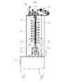
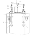
図1から図2を参照し、これから本願が提案する表面処理機器100を説明する。前記表面処理機器100は機器フレーム11、円盤ハンガー40、二つの支持輪51、回転駆動機構60、垂直スプレーフレーム20と昇降機構30とを含む。円盤ハンガー40は回路基板に対する加工や処理を容易にするように、回路基板を挟持するためのものである。回転駆動機構60は機器フレーム11上に支持されており、回転駆動機構60は二つの支持輪51上に支持された円盤ハンガー40の回転を駆動するためのものである。二つの支持輪51は機器フレーム11上に支持されており、二つの支持輪51は、円盤ハンガー40がすばやく回転できるように協力して円盤ハンガー40を支持するためのものである。垂直スプレーフレーム20は円盤ハンガー40上の回路基板に液体薬品をスプレーするためのものである。垂直スプレーフレーム20は昇降機構30上に支持されており、昇降機構30により垂直スプレーフレーム20をしっかり支持し、昇降機構30は機器フレーム11上に取り付けられて、機器フレーム11を通して昇降機構30と垂直スプレーフレーム20をしっかり支持する。昇降機構30は垂直スプレーフレーム20の昇降移動を駆動することで、スプレーされる液体薬品がよりよく鉛直な線をカバーするようにでき、回転駆動機構60により円盤ハンガー40の回転を駆動することで、垂直スプレーフレーム20により噴出される液体薬品が回路基板全体をカバーできるようにすることが可能で、しかも、回路基板上にスプレーされた液体薬品はよりよくかき乱されて、回路基板上を流れて、回路基板の表面に対して処理を行うことができる。垂直スプレーフレーム20が昇降移動をするので、回路基板のへりが比較的大きな衝撃を受けるのを避けて、回路基板の製造品質を保証できる。
(Example 1)
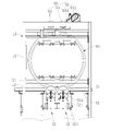
1 to 2, the
本願が提案する表面処理機器100によれば、関連技術と比べて、本願では、垂直スプレーフレーム20を設置することで、垂直スプレーを実現し、支持輪51と回転駆動機構60を設置し、円盤ハンガー40の回転を駆動して、そして昇降機構30を設置して垂直スプレーフレーム20の昇降移動を駆動し、これにより、垂直スプレーフレーム20から噴出される液体薬品が円盤ハンガー40上の回路基板をよくカバーして回路基板の表面に対して処理できるようにし、且つ、回路基板のへりが比較的大きな衝撃を受けるのを避けて、回路基板の製造品質を保証する。
According to the
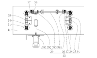
一つの実施例において、図3と図4を参照し、表面処理機器100はさらにガイドレール12、ガイドストリップ13と二つの昇降器52を含む。二つの昇降器52、ガイドレール12、ガイドストリップ13はそれぞれ機器フレーム11上に取り付けられている。二つの支持輪51は二つの昇降器52上にそれぞれ取り付けられて、二つの昇降器52を通して二つの支持輪51の昇降をそれぞれ駆動し、さらに二つの支持輪51が協力して円盤ハンガー40を支持することで、円盤ハンガー40を回転駆動機構60と移動して接触させて、回転駆動機構60で円盤ハンガー40の回転を駆動できるようにする。二つの支持輪51の両側にはそれぞれガイドレール12が設置され、ガイドレール12は円盤ハンガー40の移動を案内して、円盤ハンガー40を輸送するためのもので、ガイドストリップ13は円盤ハンガー40の上側を支持するためのものであり、円盤ハンガー40がガイドレール12上を転動して輸送される場合、ガイドストリップ13で円盤ハンガー40の両面を止めて、円盤ハンガー40を鉛直に保ち、円盤ハンガー40のガイドレール12上の転動を容易にする。
In one embodiment, referring to FIGS. 3 and 4, the
一つの実施例において、図3と図4を参照し、回転駆動機構60は主動輪61と回転組立体63とを含み、主動輪61は機器フレーム11上に回転するように取り付けられ、回転組立体63は機器フレーム11上に支持されており、主動輪61は二つの支持輪51と協力して円盤ハンガー40をしっかり挟持するためのものであり、これにより主動輪61の回転時に、円盤ハンガー40の回転を駆動できる。
In one embodiment, referring to FIGS. 3 and 4, the
一つの実施例において、図3と図4を参照し、回転組立体63は回転モータ631、主動輪61と接続されたギアセット633及びギアセット633と主動輪61とを接続するチェーン伝動構造632とを含む。主動輪61は機器フレーム11上に回転するように取り付けられ、回転組立体63は機器フレーム11上に支持されている。チェーン伝動構造632を利用することで、回転モータ631の位置を配置しやすくして、取り付けの精度を下げることができる。もちろん、いくつかの実施例において、直接回転モータ631により主動輪61の回転を駆動できる。いくつかの他の実施例において、ギアセット633で回転モータ631と主動輪61とを接続することで、主動輪61の精確な回転を保証して、円盤ハンガー40の位置決めを精確に行うことが可能となる。
In one embodiment, referring to FIGS. 3 and 4, the rotating
一つの実施例において、図3と図4を参照し、回転駆動機構60はさらに補助輪62を含み、補助輪62は機器フレーム11上に回転するように取り付けられており、二つの支持輪51が円盤ハンガー40の上昇を駆動する場合、補助輪62は主動輪61と協力して円盤ハンガー40に押し付けられて、よりよく円盤ハンガー40の位置を決めて、そして、主動輪61をよりよく円盤ハンガー40に押し付けることで、主動輪61でよりよく円盤ハンガー40の回転を駆動できるようにする。
In one embodiment, referring to FIGS. 3 and 4, the
一つの実施例において、図3と図4を参照し、補助輪62はギアセット633と接続されて、ギアセット633で補助輪62の回転を駆動しやすくして、さらには補助輪62及び主動輪61で同時に円盤ハンガー40の回転を駆動することで、より安定して円盤ハンガー40の回転を駆動する。
In one embodiment, referring to FIGS. 3 and 4, the
一つの実施例において、図3と図4を参照し、昇降器52は支持シート521、偏心カム522と回転器523を含み、回転器523は機器フレーム11上に取り付けられ、支持輪51は対応する支持シート521上に回転するように取り付けられており、支持シート521は機器フレーム11上にスライドするように取り付けられて、支持シート521により支持輪51が機器フレーム11上で昇降移動するように駆動できるようにする。偏心カム522は回転器523上に取り付けられて、回転器523により偏心カム522の回転を駆動して、さらには支持シート521を押して昇降させる。偏心カム522の回転により支持シート521を押して昇降させることで、回転器523を支持輪51の真下に設置するのを避けることが可能で、さらには加工後の回路基板上の処理液が回転器523上に落ちるのを避けて、回転器523を保護できる。一つの実施例において、回転器523としては、回転モータ631、回転エアシリンダなどを利用できる。
In one embodiment, referring to FIGS. 3 and 4, the
一つの実施例において、昇降器52はさらに支持シート521を引っ張って降下させる弾性引張り部材524を含み、弾性引張り部材524の上端は支持シート521と接続されて、弾性引張り部材524の下端は機器フレーム11と接続されている。弾性引張り部材524により支持シート521を偏心カム522に当接させることで、偏心カム522で支持シート521を押して昇降させやすくする。一実施例において、弾性引張り部材524はばねである。いくつかの実施例において、弾性引張り部材524は弾性縄としてもよい。
In one embodiment, the
いくつかの実施例において、昇降器52は支持輪51を支持する支持ロッドと支持ロッドの昇降を駆動する昇降構造を含んでもよい。昇降ロッドはエアシリンダ、送りねじナット機構などとすることができる。昇降構造は機器フレーム11の頂部に取り付けられてもよく、回路基板上の処理液が昇降構造上に落ちてしまうのを避けることも可能である。
In some embodiments, the
本願実施例の円盤ハンガー40のロード・アンロード過程は以下になる。
The loading/unloading process of the
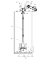
図2と図3を参照し、円盤ハンガー40がガイドレール12上を転動して輸送されて、二つの支持輪51において、ガイドレール12の輸送方向下流に位置する一つの昇降器52は対応する支持輪51を押して上昇させることで、円盤ハンガー40を止めて、円盤ハンガー40が二つの支持輪51の間に転動した時、もう一つの昇降器52がガイドレール12の輸送方向上流に位置する支持輪51を押して上昇させることで、二つの支持輪51が協力して円盤ハンガー40を押して上昇させて、円盤ハンガー40を主動輪61と補助輪62に当接させて、回転組立体63により主動輪61の回転を駆動することで、円盤ハンガー40の回転を駆動し、昇降機構30により垂直スプレーフレーム20の昇降移動を駆動して、垂直スプレーフレーム20から円盤ハンガー40上の回路基板へ液体薬品をスプレーして、回路基板に対して表面処理を行う。回路基板の表面処理が完成すると、ガイドレール12の輸送方向下流に位置する一つの昇降器52が対応する支持輪51を押して降下させて、そしてガイドレール12の輸送方向上流に位置する一つの昇降器52が対応する支持輪51を押して降下させる。ガイドレール12の輸送方向上流に位置する一つの昇降器52が対応する支持輪51を押して降下させる過程で、円盤ハンガー40が主動輪61から分離して、前へガイドレール12の下に転動して、次の加工位置に転動して輸送される。
2 and 3, the
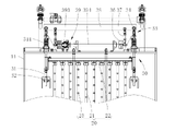
一つの実施例において、図1と図5を参照し、垂直スプレーフレーム20は二つあって、二つの垂直スプレーフレーム20は並列して円盤ハンガー40の両側に設置されている。二つの垂直スプレーフレーム20を設置することで、同時に回路基板の両面に液体薬品をスプレーして、回路基板に対して表面処理をよりよく行い、効率を向上させることが可能となる。勿論、いくつかの実施例では、一つの垂直スプレーフレーム20だけを設置して、回路基板の片面に対してスプレーしてもよい。
In one embodiment, referring to FIGS. 1 and 5, there are two vertical spray frames 20, and the two vertical spray frames 20 are installed on both sides of the
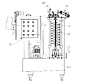
一つの実施例では、図5を参照し、垂直スプレーフレーム20は複数のスプレー管21と支柱22を含み、各スプレー管21は支柱22上に取り付けられて、支柱22を通して各スプレー管21を支持する。複数のスプレー管21を鉛直面上に配置して、且つ各スプレー管21上に複数のノズル23を取り付けることで、垂直スプレーを行う。支柱22は昇降機構30と接続されて、昇降機構30を通して支柱22の昇降を駆動して、さらには各スプレー管21及びそれらのノズル23の昇降移動を駆動する。いくつかの実施例では、中空の板を使用して、この板上にノズル23を取り付けて、且つこの板を鉛直に設置して、垂直スプレーフレーム20を構成してもよい。
In one embodiment, referring to FIG. 5, a
一つの実施例において、各スプレー管21を鉛直に設置して、複数のスプレー管21を水平方向に配置することで、各ノズル23を一つの鉛直面上に配置することを実現する。勿論、いくつかの実施例において、各スプレー管21を水平に設置して、複数のスプレー管21を鉛直方向に配置することで、各ノズル23を一つの鉛直面上に配置してもよい。
In one embodiment, each
一つの実施例では、垂直スプレーフレーム20の昇降を直接駆動するように、昇降機構30は送りねじナット機構、リニアモータ、エアシリンダなどの直線移動機構としてもよい。
In one embodiment, the
一つの実施例において、図5から図7を参照し、昇降機構30は昇降ロッド31、案内シート32と昇降駆動機構33を含み、各垂直スプレーフレーム20上にそれぞれ昇降ロッド31を接続して、昇降ロッド31により対応する垂直スプレーフレーム20を支持する。昇降ロッド31は機器フレーム11上にスライドするように取り付けられて、案内シート32と昇降ロッド31とは一対一対応であるので、案内シート32により昇降ロッド31の昇降移動を駆動する。案内シート32はガイドスリーブ、ガイドリングなどの構造としてもよい。案内シート32を昇降ロッド31上にかぶせて、昇降ロッド31の昇降を案内する。各案内シート32は機器フレーム11上に取り付けられている。昇降駆動機構33は機器フレーム11上に取り付けられて、昇降駆動機構33により昇降ロッド31の昇降移動を駆動して、対応する垂直スプレーフレーム20の昇降移動を駆動する。昇降ロッド31を設置することで、垂直スプレーフレーム20の昇降移動をよりよく案内して、垂直スプレーフレーム20のスムーズな昇降を保証できる。いくつかの実施例では、昇降ロッド31の昇降移動を直接駆動するように、昇降機構30は送りねじナット機構、リニアモータ、エアシリンダなどの直線移動機構としてもよい。
In one embodiment, referring to FIGS. 5 to 7, the
一つの実施例では、図5、図7と図8を参照し、昇降機構30はさらに弾性押上部材311を含み、各昇降ロッド31はそれぞれ弾性押上部材311の中に取り付けられて、弾性押上部材311の上端は昇降ロッド31と固定接続されて、弾性押上部材311の下端は機器フレーム11上に支持されて、弾性押上部材311は対応する昇降ロッド31を上へ押し上げるためのものである。弾性押上部材311により昇降ロッド31を上へ弾性的に押し上げることで、垂直スプレーフレーム20及び昇降ロッド31の一部の重力を相殺でき、昇降駆動機構33が昇降ロッド31及び対応する垂直スプレーフレーム20の昇降移動をすばやく駆動しやすくする。
In one embodiment, referring to FIGS. 5, 7 and 8, the
一つの実施例において、弾性押上部材311は弾性伸縮筒であり、例えば弾性伸縮性を持つベローズ筒でもよく、弾性伸縮ゴム筒でもよい。いくつかの実施例において、弾性押上部材311はばねでもよく、ばね骨組みを有する弾性ゴム筒でもよい。
In one embodiment, the elastic push-up
一つの実施例において、図5から図7を参照し、昇降駆動機構33はプッシュロッド34、支持シート35、ロッカーアーム37、偏心輪36及び回転駆動組立体39とを含む。回転駆動組立体39は機器フレーム11上に取り付けられ、支持シート35は機器フレーム11上に取り付けられている。プッシュロッド34の中部は支持シート35とヒンジ接続でつながっており、プッシュロッド34の両端はそれぞれ二つの垂直スプレーフレーム20に対応する昇降ロッド31とヒンジで接続されて、プッシュロッド34の中部を支持シート35とヒンジ接続でつなげることで、プッシュロッド34でシーソー構造を構成する。ロッカーアーム37が偏心輪36上に取り付けられて、偏心輪36の回転でロッカーアーム37のスイングを駆動するが、ロッカーアーム37がプッシュロッド34の一端と接続されて、さらにはプッシュロッド34の一端の昇降を駆動できるとともに、プッシュロッド34の他端の昇降を駆動できる。これにより、プッシュロッド34の両端の昇降ロッド31を同期して逆方向に昇降移動させて、さらには二つの垂直スプレーフレーム20の昇降移動を駆動する。
In one embodiment, referring to FIGS. 5-7, lift
一つの実施例において、回転駆動組立体39は回転軸394、主動軸392、方向転換器393及び昇降モータ391とを含む。偏心輪36は回転軸394上に取り付けられて、回転軸394により偏心カム36を支持して回転を駆動する。方向転換器393で主動軸392と回転軸394を接続している。一方、昇降モータ391は主動軸392と接続されて、主動軸392の回転を駆動して、さらには方向転換器393を通して回転軸394の回転を駆動して、ひいては偏心輪36の回転を駆動する。この構造によれば、昇降モータ391の位置配置を容易にする。方向転換器393としては、錐形ギア構造を使用してもよく、ウォームホイール・ウォーム構造などとしてもよい。いくつかの実施例において、直接昇降モータ391で偏心輪36の回転を駆動するか、或いは昇降モータ391で回転軸394の回転を駆動してもよい。
In one embodiment, the
一つの実施例において、昇降駆動機構33は複数のプッシュロッド34と複数の支持シート35を含む。支柱35とプッシュロッド34とは一対一対応である。各プッシュロッド34の両端にはそれぞれ昇降ロッド31がヒンジで接続されて、各プッシュロッド34の両端の昇降ロッド31は二つの垂直スプレーフレーム20とそれぞれ接続されて、より安定して各垂直スプレーフレーム20を支持して、且つ各垂直スプレーフレーム20の昇降移動をスムーズに駆動する。昇降駆動機構33はさらに接続ロッド38を含み、各プッシュロッド34の一端が接続ロッド38とヒンジで接続されて、ロッカーアーム37が接続ロッド38とヒンジで接続されることで、ロッカーアーム37を通して接続ロッド38の昇降を駆動して、さらには各プッシュロッド34の同期したスイングを駆動して、各垂直スプレーフレーム20のスムーズな昇降移動を駆動する。
In one embodiment, the
一つの実施例において、各垂直スプレーフレーム20上には複数の昇降ロッド31が接続されており、昇降駆動機構33はさらに各垂直スプレーフレーム20に対応する複数の昇降ロッド31にそれぞれ接続された接続ロッド38を含み、プッシュロッド34の両端はそれぞれ二本の接続ロッド38にヒンジで接続されている。この構造によっても、各垂直スプレーフレーム20に対応する昇降ロッド31の同期した昇降を駆動して、垂直スプレーフレーム20のスムーズな昇降を保証できる。なお、いくつかの実施例では、構造の簡略化のために、当該構造にプッシュロッド34を一つだけ設置してもよい。
In one embodiment, a plurality of lifting
一つの実施例において、図5から図6を参照し、よりスムーズに接続ロッド38の昇降移動を駆動するように、回転軸394上には複数の偏心輪36が取り付けられており、各偏心輪36上にはそれぞれロッカーアーム37が取り付けられて、各ロッカーアーム37はいずれも接続ロッド38とヒンジで接続されている。勿論、いくつかの実施例において、ロッカーアーム37及び偏心輪36はいずれも一つとしてもよい。
In one embodiment, referring to FIGS. 5-6, a plurality of
一つの実施例において、図1を参照し、垂直スプレーフレーム20によりスプレーされた液体薬品を集めて汚染を防止し、且つ液体薬品を回収してリサイクルするために、機器フレーム11の下端にはさらに集液槽111が設置されている。
In one embodiment, referring to FIG. 1, the lower end of the
本願実施例の表面処理機器100は回路基板に対してエッチングするためのエッチング機器でもよく、回路基板を洗浄するための洗浄機器でもよく、回路基板に対してフィルム剥離を行うためのフィルム剥離機器でもよい。勿論、回路基板処理プロセスでスプレーが必要とされる場合、本実施例の表面処理機器100を利用することも可能である。
The
(実施例二)
図9と図10を参照し、本実施例の表面処理機器100と実施例一の表面処理機器100との区別は以下になる。
(Example 2)
9 and 10, the distinction between the
本実施例において、回転組立体63は回転モータ631及び回転モータ631を主動輪61と接続するチェーン伝動構造632とを含む。チェーン伝動構造632を利用することで、回転モータ631の位置を配置しやすくして、取り付けの精度を下げることができる。実施例一に比べて、当該構造は回転組立体63の構造を簡略化した。
In this embodiment, the rotating
一つの実施例において、円盤ハンガー40の回転駆動機構60はさらに補助輪62を含み、補助輪62は機器フレーム11上に回転するように取り付けられており、二つの支持輪51が円盤ハンガー40の上昇を駆動する場合、補助輪62は主動輪61と協力して円盤ハンガー40に押し付けられて、よりよく円盤ハンガー40の位置を決めて、そして、主動輪61をよりよく円盤ハンガー40に押し付けることで、主動輪61で円盤ハンガー40の回転を駆動する場合、補助輪62が円盤ハンガー40とともに回転して、円盤ハンガー40のスムーズで素早い回転を保証する。なお、実施例一と比べ、この構造は構造を簡略化して、組立を容易にして、コストを下げた。
In one embodiment, the
本実施例の表面処理機器100の他の構造は実施例一の表面処理機器100の他の構造とは同じなので、ここでは改めて説明をしない。
Since other structures of the
(実施例三)
図11を参照し、本実施例の表面処理機器100と実施例一の表面処理機器100との区別は以下になる。
(Example 3)
Referring to FIG. 11, the distinction between the
本実施例では、表面処理機器100はさらに残渣ろ過装置70を含む。残渣ろ過装置70を設置することで、回収された液体薬品にろ過を行い、回収された液体薬品中の残渣、不純物などをろ過で除去できる。この表面処理機器100は回路基板処理のフィルム剥離機器とすることが可能であり、その場合、残渣ろ過装置70で液体薬品中の残渣フィルムに対してろ過を行える。
In this example, the
本実施例の表面処理機器100の他の構造は実施例一の表面処理機器100の他の構造とは同じなので、ここでは改めて説明をしない。
Since other structures of the
以上に述べたのは本願の好ましい実施例に過ぎず、本願を制限するためのものではない。本願の精神と原則内で行われた任意の修正、均等物による置換、改良等は、いずれも本願の保護範囲内に含まれるべきである。 The above are only preferred embodiments of the present application and are not intended to limit the present application. Any modification, equivalent replacement, improvement, etc. made within the spirit and principle of the present application shall all fall within the protection scope of the present application.
図における各図面の主な符号は以下になる。
100 表面処理機器、
11 機器フレーム、
111 集液槽、
12 ガイドレール、
13 ガイドストリップ、
20 垂直スプレーフレーム、
21 スプレー管、
22 支柱、
23 ノズル、
30 昇降機構、
31 昇降ロッド、
311 弾性押上部材、
32 案内シート、
33 昇降駆動機構、
34 プッシュロッド、
35 支えシート、
36 偏心輪、
37 ロッカーアーム、
38 接続ロッド、
39 回転駆動組立体、
391 昇降モータ、
392 主動軸、
393 方向転換器、
394 回転軸、
40 円盤ハンガー、
51 支持輪、
52 昇降器、
521 支持シート、
522 偏心カム、
523 回転器、
524 弾性引張り部材、
60 回転駆動機構、
61 主動輪、
62 補助輪、
63 回転組立体、
631 回転モータ、
632 チェーン伝動構造、
633 ギアセット、
70 残渣ろ過装置。
Main reference numerals of each drawing in the figure are as follows.
100 surface treatment equipment,
11 equipment frame,
111 liquid collecting tank,
12 guide rails,
13 guide strips,
20 vertical spray frame,
21 spray tube,
22 struts,
23 nozzles,
30 lifting mechanism,
31 lifting rod,
311 elastic push-up member,
32 guide sheet,
33 lift drive mechanism,
34 push rod,
35 support sheet,
36 eccentric wheel,
37 rocker arm,
38 connecting rods,
39 rotary drive assembly;
391 lifting motor,
392 main driving shaft,
393 diverters,
394 axis of rotation,
40 disk hanger,
51 support ring,
52 Elevator,
521 support sheet;
522 eccentric cam,
523 rotator,
524 elastic tension member;
60 rotary drive mechanism,
61 main driving wheel,
62 training wheels,
63 rotating assembly,
631 rotary motor,
632 chain transmission structure,
633 gear set,
70 Residue filtering device.
Claims (15)
回路基板を挟持するための円盤ハンガーと、
前記機器フレーム上に支持されて、前記円盤ハンガーを協力して支持するための二つの支持輪と、
前記機器フレーム上に支持されて、二つの前記支持輪上に支持された前記円盤ハンガーの回転を駆動するための回転駆動機構と、
前記円盤ハンガー上の回路基板に液体薬品をスプレーするための垂直スプレーフレームと、
前記機器フレーム上に取り付けられて、前記垂直スプレーフレームの昇降移動を駆動するための昇降機構と、を含み、
前記垂直スプレーフレームは前記昇降機構上に取り付けられている、
ことを特徴とする表面処理機器。 an equipment frame;
a disc hanger for clamping the circuit board;
two support wheels supported on the equipment frame for cooperatively supporting the disk hanger;
a rotary drive mechanism supported on the equipment frame for driving rotation of the disc hanger supported on two of the support wheels;
a vertical spray frame for spraying liquid chemicals onto circuit boards on the disk hanger;
a lifting mechanism mounted on the equipment frame for driving lifting movement of the vertical spray frame;
the vertical spray frame is mounted on the lifting mechanism;
A surface treatment device characterized by:
ことを特徴とする請求項1に記載の表面処理機器。 There are two vertical spray frames, the two vertical spray frames are installed side by side on both sides of the disk hanger, the lifting mechanism is a lifting rod respectively connected to each vertical spray frame, A guide sheet for guiding the vertical movement of a lifting rod and a lifting drive mechanism for driving the lifting rod, wherein the lifting drive mechanism is mounted on the equipment frame, and the guide sheet is mounted on the equipment frame. and wherein the lifting rod is slidably mounted on the equipment frame;
The surface treatment equipment according to claim 1, characterized in that:
ことを特徴とする請求項2に記載の表面処理機器。 The lifting drive mechanism drives a push rod whose both ends are respectively hinged with the lifting rod corresponding to each of the vertical spray frames, a support sheet supporting the middle part of the push rod, and one end of the push rod to move up and down. a rocker arm, an eccentric for driving swing of the rocker arm, and a rotary drive assembly for driving rotation of the eccentric, wherein the rotary drive assembly is mounted on the machine frame; mounted on an equipment frame, the middle portion of the push rod being hinged to the support seat;
3. The surface treatment equipment according to claim 2, characterized in that:
ことを特徴とする請求項3に記載の表面処理機器。 The rotary drive assembly includes a rotating shaft supporting the eccentric wheel, a main driving shaft driving the rotation of the rotating shaft, a direction changer connecting the main driving shaft and the rotating shaft, and an elevating motor driving the rotation of the main driving shaft. wherein the lifting motor is mounted on the equipment frame, and the main drive shaft and the rotary shaft are each mounted for rotation on the equipment frame;
4. The surface treatment equipment according to claim 3, characterized in that:
ことを特徴とする請求項3に記載の表面処理機器。 The lifting drive mechanism includes a plurality of push rods and a plurality of support sheets for supporting the push rods. The lifting rods at both ends are respectively connected with the two vertical spray frames, the lifting drive mechanism further includes a connecting rod, one end of each of the push rods is hingedly connected with the connecting rod, and the rocker arm is connected to the connected by connecting rods and hinges,
4. The surface treatment equipment according to claim 3, characterized in that:
ことを特徴とする請求項2に記載の表面処理機器。 The elevating mechanism further includes an elastic push-up member for elastically pushing up the corresponding elevating rod, the upper end of the elastic push-up member is fixedly connected with the elevating rod, and the lower end of the elastic push-up member is connected to the device. supported on the frame,
3. The surface treatment equipment according to claim 2, characterized in that:
二つの前記支持輪の両側にそれぞれ設置されて、前記円盤ハンガーの輸送を案内するためのガイドレールと、
前記機器フレーム上に取り付けられて、前記円盤ハンガーの上側を支持するためのガイドストリップと、
前記機器フレーム上に取り付けられて、二つの前記支持輪の昇降移動をそれぞれ駆動するための二つの昇降器とを含み、
二つの前記支持輪は二つの前記昇降器上にそれぞれ取り付けられている、
ことを特徴とする請求項1~6の何れか一項に記載の表面処理機器。 The surface treatment equipment further comprises:
guide rails respectively installed on both sides of the two support wheels for guiding the transportation of the disc hanger;
a guide strip mounted on the equipment frame for supporting an upper side of the disk hanger;
two elevators mounted on the equipment frame for respectively driving the lifting movement of the two support wheels;
two said support wheels are respectively mounted on two said elevators,
The surface treatment equipment according to any one of claims 1 to 6, characterized in that:
ことを特徴とする請求項7に記載の表面処理機器。 The elevator includes a support sheet slidably mounted on the equipment frame, an eccentric cam that pushes and lifts the support sheet, and a rotator that drives rotation of the eccentric cam, wherein the rotator is the equipment frame. and the support wheels are mounted for rotation on the corresponding support seats.
The surface treatment equipment according to claim 7, characterized in that:
ことを特徴とする請求項8に記載の表面処理機器。 The elevator further comprises an elastic tension member for pulling and lowering the support sheet, the upper end of the elastic tension member is connected with the support sheet, and the lower end of the elastic tension member is connected with the equipment frame.
The surface treatment equipment according to claim 8, characterized in that:
ことを特徴とする請求項1~6の何れか一項に記載の表面処理機器。 The rotary drive mechanism includes a main driving wheel for sandwiching the disk hanger and driving the rotation of the disk hanger in cooperation with the two support wheels, and a rotating assembly for driving the rotation of the main driving wheel; said main driving wheel is mounted for rotation on said equipment frame and said rotating assembly is supported on said equipment frame;
The surface treatment equipment according to any one of claims 1 to 6, characterized in that:
ことを特徴とする請求項10に記載の表面処理機器。 the rotary drive mechanism further includes an auxiliary wheel for being pressed against the disk hanger in cooperation with the main driving wheel, the auxiliary wheel being mounted for rotation on the equipment frame;
11. The surface treatment equipment according to claim 10, characterized in that:
ことを特徴とする請求項10に記載の表面処理機器。 The rotating assembly includes a rotating motor, a gear set connected with the main driving wheel, and a chain transmission structure connecting the gear set and the main driving wheel, the main driving wheel rotating on the machine frame. mounted, the rotary motor is supported on the equipment frame,
11. The surface treatment equipment according to claim 10, characterized in that:
ことを特徴とする請求項1~6の何れか一項に記載の表面処理機器。 The vertical spray frame includes a plurality of spray tubes arranged in a vertical plane and a column supporting each of the spray tubes, each of the spray tubes having a plurality of nozzles mounted thereon, and the column supporting the elevating mechanism. connected with
The surface treatment equipment according to any one of claims 1 to 6, characterized in that:
ことを特徴とする請求項13に記載の表面処理機器。 Each spray tube is installed vertically, and a plurality of the spray tubes are arranged horizontally,
14. The surface treatment equipment according to claim 13, characterized by:
ことを特徴とする請求項1~6の何れか一項に記載の表面処理機器。
The surface treatment equipment further includes a residue filtration device for filtering and recovering the liquid chemicals.
The surface treatment equipment according to any one of claims 1 to 6, characterized in that:
Applications Claiming Priority (3)
| Application Number | Priority Date | Filing Date | Title |
|---|---|---|---|
| CN202010612375.9A CN111712048A (en) | 2020-06-30 | 2020-06-30 | Surface treatment equipment |
| CN202010612375.9 | 2020-06-30 | ||
| PCT/CN2020/107621 WO2022000703A1 (en) | 2020-06-30 | 2020-08-07 | Surface treatment device |
Publications (1)
| Publication Number | Publication Date |
|---|---|
| JP2022541862A true JP2022541862A (en) | 2022-09-28 |
Family
ID=73460616
Family Applications (1)
| Application Number | Title | Priority Date | Filing Date |
|---|---|---|---|
| JP2020558902A Pending JP2022541862A (en) | 2020-06-30 | 2020-08-07 | surface treatment equipment |
Country Status (4)
| Country | Link |
|---|---|
| US (1) | US20210402424A1 (en) |
| JP (1) | JP2022541862A (en) |
| KR (1) | KR102396878B1 (en) |
| GB (1) | GB2601472B (en) |
Citations (7)
| Publication number | Priority date | Publication date | Assignee | Title |
|---|---|---|---|---|
| JPH0263199A (en) * | 1988-08-29 | 1990-03-02 | Matsushita Electric Ind Co Ltd | Electronic component mounting equipment and electronic component mounting method |
| JPH03195086A (en) * | 1989-12-25 | 1991-08-26 | Ibiden Co Ltd | Patterning method and device of printed wiring board |
| JPH05175637A (en) * | 1991-12-26 | 1993-07-13 | Toshiba Corp | Etching device |
| JP2013207025A (en) * | 2012-03-28 | 2013-10-07 | Panasonic Corp | Method of manufacturing printed wiring board |
| JP3186505U (en) * | 2013-07-29 | 2013-10-10 | 揚博科技股▲ふん▼有限公司 | Circuit board clamping jig having a rotation mechanism |
| KR20180059997A (en) * | 2016-11-28 | 2018-06-07 | 김훈 | Substrate rotation type injection spray apparatus |
| WO2019020318A1 (en) * | 2017-07-26 | 2019-01-31 | Gebr. Schmid Gmbh | METHOD, DEVICE AND PLANT FOR PCB CONSTRUCTION |
Family Cites Families (14)
| Publication number | Priority date | Publication date | Assignee | Title |
|---|---|---|---|---|
| US3849906A (en) * | 1973-11-07 | 1974-11-26 | Ibm | Rotary fluid applicator |
| US20050194356A1 (en) * | 1997-05-09 | 2005-09-08 | Semitool, Inc. | Removing photoresist from a workpiece using water and ozone and a photoresist penetrating additive |
| US6225235B1 (en) * | 2000-02-18 | 2001-05-01 | Horst Kunze-Concewitz | Method and device for cleaning and etching individual wafers using wet chemistry |
| US10179351B2 (en) * | 2005-02-07 | 2019-01-15 | Planar Semiconductor, Inc. | Method and apparatus for cleaning flat objects with pulsed liquid jet |
| JP2006324549A (en) * | 2005-05-20 | 2006-11-30 | Sony Corp | Element transfer device, element transfer method, and display device manufacturing method |
| CN101051604A (en) * | 2006-04-07 | 2007-10-10 | 悦城科技股份有限公司 | Method and device for panel etching process |
| US9418831B2 (en) * | 2007-07-30 | 2016-08-16 | Planar Semiconductor, Inc. | Method for precision cleaning and drying flat objects |
| CN101992165B (en) * | 2009-08-27 | 2012-10-24 | 沈阳芯源微电子设备有限公司 | Device for chemical liquid spraying treatment of round lamellar object |
| US9744565B2 (en) * | 2012-12-14 | 2017-08-29 | Beijing Sevenstar Electronics Co., Ltd. | Swing spray device of cleaning apparatus and cleaning method |
| KR102123335B1 (en) * | 2015-01-12 | 2020-06-17 | 어플라이드 머티어리얼스, 인코포레이티드 | A holding arrangement for supporting a substrate carrier and a mask carrier during layer deposition in a processing chamber, an apparatus for depositing a layer on a substrate, and a method for aligning a mask carrier with a substrate carrier supporting a substrate |
| JP2017076639A (en) * | 2015-10-13 | 2017-04-20 | チャンソン カンパニー,リミテッドChangsung Co.,Ltd | Board developing system |
| CN109904094B (en) * | 2019-01-17 | 2021-02-19 | 安徽华顺半导体发展有限公司 | Polycrystalline silicon ingot silicon chip cleaning equipment |
| CN110404852B (en) * | 2019-07-18 | 2021-02-26 | 武汉华星光电半导体显示技术有限公司 | Spraying device |
| CN210444588U (en) * | 2019-08-18 | 2020-05-01 | 广德东风电子有限公司 | A spray set for production of PCB board |
-
2020
- 2020-08-07 JP JP2020558902A patent/JP2022541862A/en active Pending
- 2020-08-07 GB GB2016189.9A patent/GB2601472B/en active Active
- 2020-08-07 KR KR1020207029818A patent/KR102396878B1/en active Active
- 2020-09-25 US US17/032,293 patent/US20210402424A1/en not_active Abandoned
Patent Citations (8)
| Publication number | Priority date | Publication date | Assignee | Title |
|---|---|---|---|---|
| JPH0263199A (en) * | 1988-08-29 | 1990-03-02 | Matsushita Electric Ind Co Ltd | Electronic component mounting equipment and electronic component mounting method |
| JPH03195086A (en) * | 1989-12-25 | 1991-08-26 | Ibiden Co Ltd | Patterning method and device of printed wiring board |
| JPH05175637A (en) * | 1991-12-26 | 1993-07-13 | Toshiba Corp | Etching device |
| JP2013207025A (en) * | 2012-03-28 | 2013-10-07 | Panasonic Corp | Method of manufacturing printed wiring board |
| JP3186505U (en) * | 2013-07-29 | 2013-10-10 | 揚博科技股▲ふん▼有限公司 | Circuit board clamping jig having a rotation mechanism |
| KR20180059997A (en) * | 2016-11-28 | 2018-06-07 | 김훈 | Substrate rotation type injection spray apparatus |
| WO2019020318A1 (en) * | 2017-07-26 | 2019-01-31 | Gebr. Schmid Gmbh | METHOD, DEVICE AND PLANT FOR PCB CONSTRUCTION |
| JP2020528219A (en) * | 2017-07-26 | 2020-09-17 | ゲブリューダー シュミット ゲゼルシャフト ミット ベシュレンクテル ハフツング | Methods, devices and systems for manufacturing printed circuit boards |
Also Published As
| Publication number | Publication date |
|---|---|
| KR20220003951A (en) | 2022-01-11 |
| KR102396878B1 (en) | 2022-05-12 |
| GB202016189D0 (en) | 2020-11-25 |
| US20210402424A1 (en) | 2021-12-30 |
| GB2601472B (en) | 2025-06-11 |
| GB2601472A (en) | 2022-06-08 |
| GB2601472A9 (en) | 2022-07-13 |
Similar Documents
| Publication | Publication Date | Title |
|---|---|---|
| JP3230031U (en) | Surface treatment equipment | |
| CN110641125A (en) | Full-automatic net cage laminating machine | |
| CN204160867U (en) | Novel stencil printer | |
| CN105500879B (en) | Laptop and tablet computer laminator | |
| CN116423985B (en) | PCB text printing ink-jet printing system and control method thereof | |
| JP2022541862A (en) | surface treatment equipment | |
| CN114030277A (en) | Battery piece printing device and printing method | |
| CN213315692U (en) | Vertical spraying device and surface treatment equipment | |
| CN212677458U (en) | Surface treatment apparatus | |
| CN110027756B (en) | Rotatory fifty percent discount integrated platform of compression mattress | |
| CN115285639B (en) | Panel re-judging device | |
| CN113415733B (en) | Large-scale storage tank jack-up lifting device of industry | |
| CN212711640U (en) | Automatic feeding machine for printing plate | |
| CN210337233U (en) | Screen printing equipment | |
| CN211100304U (en) | L CD surface impression removing mechanism and L CD cleaning device | |
| CN210362920U (en) | A stencil printing equipment | |
| CN113830528A (en) | New automatic separation device and automatic separation method of carrier glass and coated products | |
| CN218906352U (en) | Supporting structure and glue pool for film compound machine | |
| CN208747234U (en) | Material feeding device | |
| CN113184536B (en) | Online weighing device is used in glass substrate processing | |
| CN218808975U (en) | Plate carrying device | |
| CN218833757U (en) | Filter with filter cloth replaced by rapid slag removal | |
| CN210594532U (en) | Guiding mechanism for printed matter | |
| CN222061207U (en) | Acrylic plate embossing equipment | |
| CN218224081U (en) | Pattern plate rolling device |
Legal Events
| Date | Code | Title | Description |
|---|---|---|---|
| A621 | Written request for application examination |
Free format text: JAPANESE INTERMEDIATE CODE: A621 Effective date: 20201019 |
|
| A131 | Notification of reasons for refusal |
Free format text: JAPANESE INTERMEDIATE CODE: A131 Effective date: 20220927 |
|
| A521 | Request for written amendment filed |
Free format text: JAPANESE INTERMEDIATE CODE: A523 Effective date: 20221227 |
|
| A02 | Decision of refusal |
Free format text: JAPANESE INTERMEDIATE CODE: A02 Effective date: 20230322 |